EP3912418B1 - Adaptives direktzugriffsantwortfenster - Google Patents
Adaptives direktzugriffsantwortfenster Download PDFInfo
- Publication number
- EP3912418B1 EP3912418B1 EP19850593.5A EP19850593A EP3912418B1 EP 3912418 B1 EP3912418 B1 EP 3912418B1 EP 19850593 A EP19850593 A EP 19850593A EP 3912418 B1 EP3912418 B1 EP 3912418B1
- Authority
- EP
- European Patent Office
- Prior art keywords
- delay
- propagation delay
- communication device
- random access
- satellite
- Prior art date
- Legal status (The legal status is an assumption and is not a legal conclusion. Google has not performed a legal analysis and makes no representation as to the accuracy of the status listed.)
- Active
Links
Images


Classifications
-
- H—ELECTRICITY
- H04—ELECTRIC COMMUNICATION TECHNIQUE
- H04W—WIRELESS COMMUNICATION NETWORKS
- H04W74/00—Wireless channel access
- H04W74/08—Non-scheduled access, e.g. ALOHA
- H04W74/0833—Random access procedures, e.g. with 4-step access
- H04W74/0836—Random access procedures, e.g. with 4-step access with 2-step access
-
- H—ELECTRICITY
- H04—ELECTRIC COMMUNICATION TECHNIQUE
- H04B—TRANSMISSION
- H04B7/00—Radio transmission systems, i.e. using radiation field
- H04B7/14—Relay systems
- H04B7/15—Active relay systems
- H04B7/185—Space-based or airborne stations; Stations for satellite systems
- H04B7/1851—Systems using a satellite or space-based relay
-
- H—ELECTRICITY
- H04—ELECTRIC COMMUNICATION TECHNIQUE
- H04W—WIRELESS COMMUNICATION NETWORKS
- H04W56/00—Synchronisation arrangements
-
- H—ELECTRICITY
- H04—ELECTRIC COMMUNICATION TECHNIQUE
- H04W—WIRELESS COMMUNICATION NETWORKS
- H04W56/00—Synchronisation arrangements
- H04W56/004—Synchronisation arrangements compensating for timing error of reception due to propagation delay
- H04W56/0045—Synchronisation arrangements compensating for timing error of reception due to propagation delay compensating for timing error by altering transmission time
-
- H—ELECTRICITY
- H04—ELECTRIC COMMUNICATION TECHNIQUE
- H04W—WIRELESS COMMUNICATION NETWORKS
- H04W56/00—Synchronisation arrangements
- H04W56/0055—Synchronisation arrangements determining timing error of reception due to propagation delay
-
- H—ELECTRICITY
- H04—ELECTRIC COMMUNICATION TECHNIQUE
- H04W—WIRELESS COMMUNICATION NETWORKS
- H04W74/00—Wireless channel access
- H04W74/002—Transmission of channel access control information
-
- H—ELECTRICITY
- H04—ELECTRIC COMMUNICATION TECHNIQUE
- H04W—WIRELESS COMMUNICATION NETWORKS
- H04W74/00—Wireless channel access
- H04W74/002—Transmission of channel access control information
- H04W74/006—Transmission of channel access control information in the downlink, i.e. towards the terminal
-
- H—ELECTRICITY
- H04—ELECTRIC COMMUNICATION TECHNIQUE
- H04W—WIRELESS COMMUNICATION NETWORKS
- H04W74/00—Wireless channel access
- H04W74/08—Non-scheduled access, e.g. ALOHA
- H04W74/0833—Random access procedures, e.g. with 4-step access
-
- H—ELECTRICITY
- H04—ELECTRIC COMMUNICATION TECHNIQUE
- H04W—WIRELESS COMMUNICATION NETWORKS
- H04W84/00—Network topologies
- H04W84/02—Hierarchically pre-organised networks, e.g. paging networks, cellular networks, WLAN [Wireless Local Area Network] or WLL [Wireless Local Loop]
- H04W84/04—Large scale networks; Deep hierarchical networks
- H04W84/06—Airborne or Satellite Networks
-
- H—ELECTRICITY
- H04—ELECTRIC COMMUNICATION TECHNIQUE
- H04W—WIRELESS COMMUNICATION NETWORKS
- H04W48/00—Access restriction; Network selection; Access point selection
- H04W48/08—Access restriction or access information delivery, e.g. discovery data delivery
- H04W48/12—Access restriction or access information delivery, e.g. discovery data delivery using downlink control channel
Definitions
- This disclosure relates generally to wireless communications and, more particularly, to systems and methods for determining an adaptive random access response window length in non-terrestrial networks.
- Timing for random access may be dependent upon an amount of delay time that communications are in transition between a transmitter and receiver.
- Current techniques for random access may account for delay time within terrestrial networks (e.g., communications between devices on the Earth) but not for non-terrestrial networks (e.g., communications between a satellite orbiting the Earth and a device not orbiting the Earth). Therefore, current techniques for random access may not be entirely satisfactory.
- 3GPP Draft R2-1818510, 3GPP Draft RP-180658 pages 1-37 and 3GPP Draft R1-1804395 are related prior art documents, addressing the problem of how to achieve power saving in random access response monitoring, when considering the propagation delay for mobile communications in Non-Terrestrial Networks, or NTN.
- exemplary embodiments disclosed herein are directed to solving the issues relating to one or more of the problems presented in the prior art, as well as providing additional features that will become readily apparent by reference to the following detailed description when taken in conjunction with the accompany drawings.
- exemplary systems, methods, devices and computer program products are disclosed herein. It is understood, however, that these embodiments are presented by way of example and not limitation.
- FIG. 1 illustrates an exemplary wireless communication network 100 in which techniques disclosed herein may be implemented, in accordance with an embodiment of the present disclosure.
- Such an exemplary network 100 includes a base station 102 (hereinafter “BS 102") and multiple user equipment devices 104 (hereinafter “UEs 104”) that can communicate with each other via respective communication links 110 (e.g., a wireless communication channel), and a cluster of notional cells 126, 130, 132, 134, 136, 138 and 140 overlaying a geographical area with a network 101.
- Each UE 104 may undergo a random access procedure to join the network 101.
- the BS 102 and each UE 104 are contained within a respective geographic boundary of cell 126.
- Each of the other cells 130, 132, 134, 136, 138 and 140 may include at least one BS operating at its allocated bandwidth to provide adequate radio coverage to its intended users. Accordingly, reference to a cell may be a short hand reference to a BS with an associated coverage region or area (e.g., cell). In certain embodiments, a cell may be interchangeably referred to as a BS or a node.
- the BS 102 may operate at an allocated channel transmission bandwidth (e.g., spectrum) to provide adequate coverage to each UE 104.
- the spectrum may be regulated to define a licensed range and/or an unlicensed range.
- the BS 102 and each UE 104 may communicate via a downlink radio frame 118, and an uplink radio frame 124 respectively.
- the radio frames may also be referred to more simply as a frame.
- Each frame 118/124 may be further divided into sub-frames 120/127 which may include data symbols 122/128.
- the BS 102 and each UE 104 are described herein as non-limiting examples of "communication nodes," generally, which can practice the methods disclosed herein.
- Such communication nodes may be capable of wireless and/or wired communications, in accordance with various embodiments of the invention.
- a communication device may refer more specifically to a UE in relationship to a BS and a communication node may refer more specifically to a BS in relation to the UE.
- Figure 2 illustrates a block diagram of an exemplary wireless communication system 200 for transmitting and receiving wireless communication signals (e.g., OFDM/OFDMA signals) in accordance with some embodiments of the invention.
- the system 200 may include components and elements configured to support known or conventional operating features that need not be described in detail herein.
- system 200 can be used to transmit and receive data symbols in a wireless communication environment such as the wireless communication environment or network 100 of Figure 1 , as described above.
- the System 200 generally includes a base station 202 (hereinafter “BS 202") and a user equipment device 204 (hereinafter “UE 204").
- the BS 202 includes a BS (base station) transceiver module 210, a BS antenna 212, a BS processor module 214, a BS memory module 216, and a network communication module 218, each module being coupled and interconnected with one another as necessary via a data communication bus 220.
- the UE 204 includes a UE (user equipment) transceiver module 230, a UE antenna 232, a UE memory module 234, and a UE processor module 236, each module being coupled and interconnected with one another as necessary via a data communication bus 240.
- the BS 202 communicates with the UE 204 via a communication channel 250, which can be any wireless channel or other medium known in the art suitable for transmission of data as described herein.
- system 200 may further include any number of modules other than the modules shown in Figure 2 .
- modules other than the modules shown in Figure 2 .
- Those skilled in the art will understand that the various illustrative blocks, modules, circuits, and processing logic described in connection with the embodiments disclosed herein may be implemented in hardware, computer-readable software, firmware, or any practical combination thereof. To clearly illustrate this interchangeability and compatibility of hardware, firmware, and software, various illustrative components, blocks, modules, circuits, and steps are described generally in terms of their functionality. Whether such functionality is implemented as hardware, firmware, or software depends upon the particular application and design constraints imposed on the overall system. Those familiar with the concepts described herein may implement such functionality in a suitable manner for each particular application, but such implementation decisions should not be interpreted as limiting the scope of the present invention.
- the UE transceiver module 230 may be referred to herein as an "uplink" transceiver module 230 that includes a RF transmitter and receiver circuitry that are each coupled to the antenna 232.
- a duplex switch (not shown) may alternatively couple the uplink transmitter or receiver to the uplink antenna in time duplex fashion.
- the BS transceiver module 210 may be referred to herein as a "downlink" transceiver module 210 that includes RF transmitter and receiver circuity that are each coupled to the antenna 212.
- a downlink duplex switch may alternatively couple the downlink transmitter or receiver to the downlink antenna 212 in time duplex fashion.
- the operations of the two transceiver modules 210 and 230 are coordinated in time such that the uplink receiver is coupled to the uplink antenna 232 for reception of transmissions over the wireless transmission link 250 at the same time that the downlink transmitter is coupled to the downlink antenna 212.
- the UE transceiver module 230 and the BS transceiver module 210 are configured to communicate via the wireless data communication link 250, and cooperate with a suitably configured RF antenna arrangement 212/232 that can support a particular wireless communication protocol and modulation scheme.
- the UE transceiver module 210 and the BS transceiver module 210 are configured to support industry standards such as the Long Term Evolution (LTE) and emerging 5G standards, and the like. It is understood, however, that the invention is not necessarily limited in application to a particular standard and associated protocols. Rather, the UE transceiver module 230 and the BS transceiver module 210 may be configured to support alternate, or additional, wireless data communication protocols, including future standards or variations thereof.
- the BS 202 may be an evolved node B (eNB), a serving eNB, a target eNB, a femto station, or a pico station, for example.
- the UE 204 may be embodied in various types of user devices such as a mobile phone, a smart phone, a personal digital assistant (PDA), tablet, laptop computer, wearable computing device, etc.
- PDA personal digital assistant
- the processor modules 214 and 236 may be implemented, or realized, with a general purpose processor, a content addressable memory, a digital signal processor, an application specific integrated circuit, a field programmable gate array, any suitable programmable logic device, discrete gate or transistor logic, discrete hardware components, or any combination thereof, designed to perform the functions described herein.
- a processor may be realized as a microprocessor, a controller, a microcontroller, a state machine, or the like.
- a processor may also be implemented as a combination of computing devices, e.g., a combination of a digital signal processor and a microprocessor, a plurality of microprocessors, one or more microprocessors in conjunction with a digital signal processor core, or any other such configuration.
- the steps of a method or algorithm described in connection with the embodiments disclosed herein may be embodied directly in hardware, in firmware, in a software module executed by processor modules 214 and 236, respectively, or in any practical combination thereof.
- the memory modules 216 and 234 may be realized as RAM memory, flash memory, ROM memory, EPROM memory, EEPROM memory, registers, a hard disk, a removable disk, a CD-ROM, or any other form of storage and/or computer-readable medium known in the art.
- memory modules 216 and 234 may be coupled to the transceiver modules 210 and 230, respectively, such that the transceiver modules 210 and 230 can read information from, and write information to, memory modules 216 and 234, respectively.
- the memory modules 216 and 234 may also be integrated into their respective transceiver modules 210 and 230.
- the memory modules 216 and 234 may each include a cache memory for storing temporary variables or other intermediate information during execution of instructions to be executed by transceiver modules 210 and 230, respectively.
- Memory modules 216 and 234 may also each include non-volatile memory for storing instructions to be executed by the transceiver modules 210 and 230, respectively.
- the network communication module 218 generally represents the hardware, software, firmware, processing logic, and/or other components of the base station 202 that enable bidirectional communication between the BS transceiver module 210 and other network components and communication nodes configured to communication with the base station 202.
- network communication module 218 may be configured to support internet or WiMAX traffic.
- network communication module 218 provides an 802.3 Ethernet interface such that the BS transceiver module 210 can communicate with a conventional Ethernet based computer network.
- the network communication module 218 may include a physical interface for connection to the computer network (e.g., Mobile Switching Center (MSC)).
- MSC Mobile Switching Center
- NTN non-terrestrial network
- the satellites may be Geostationary Earth Orbit (GEO) satellites, Low Earth Orbit (LEO) satellites or Medium Earth Orbit (MEO) satellites.
- GEO Geostationary Earth Orbit
- LEO Low Earth Orbit
- MEO Medium Earth Orbit
- RTD minimum round trip delay
- a satellite beam footprint diameter could be, for example, 500 km or even larger in diameter.
- a minimum elevation angle for a satellite beam could be, for example, as small as 5°. Either or both large beam footprints and small elevation angles may result in significantly different RTDs in a single beam.
- systems and methods in accordance with various embodiments include random access timing with an adaptive scheme (e.g., an adaptive random access response monitoring window) for different orbit altitudes, beam footprint sizes and elevation angles.
- the minimum and maximum time delay (or corresponding minimum and maximum distance) may be broadcast in system information.
- a differential delay in a specific beam may be used to determine the monitoring window length in a random access procedure.
- an adaptive random access response monitoring window length can be calculated for satellites with different orbit altitudes, satellite payload types, beam footprint sizes, and elevation angles.
- users e.g., UEs
- Figure 3 is a sequence diagram illustrating a contention based random access procedure 300, in accordance with some embodiments.
- the procedure 300 may be performed by a UE 302 and a BS 304. It is noted that the procedure 300 is merely an example, and is not intended to limit the present disclosure. Accordingly, it is understood that additional operations (e.g., blocks) may be provided before, during, and after the procedure 300 of Figure 3 , certain operations may be omitted, certain operations may be performed concurrently with other operations, and that some other operations may only be briefly described herein.
- a random access preamble message may be sent from the UE 302 to the BS 304.
- the random access preamble message of operation 310 may be referred to as a Message 1 of random access.
- a random access response message may be sent from the BS 304 to the UE 302.
- the random access response message of operation 312 may be referred to as a Message 2 of random access.
- a scheduled transmission message may be sent from the UE 302 to the BS 304.
- the scheduled transmission message of operation 312 may be referred to as a Message 3 of random access.
- a contention resolution message may be sent from the BS 304 to the UE 302.
- the contention resolution message of operation 316 may be referred to as a Message 4 of random access.
- the UE may start a timer (e.g., a ra-ResponseWindow timer) at the first physical downlink control channel (PDCCH) occasion from the end of the random access preamble message transmission.
- a timer e.g., a ra-ResponseWindow timer
- PDCCH physical downlink control channel
- the UE monitors the PDCCH while ra-ResponseWindow is running.
- the ra-ResponseWindow may have an enumerated type with range (e.g., noted with index values as sl1, sl2, sl4, sl8, sl10, sl20, sl40, sl80 defined in certain communication standards).
- a network may configure a value for the ra-ResponseWindow that is lower than or equal to 10 ms.
- the maximum delay difference experienced by different UEs e.g., a near UE and a far UE
- the current ra-ResponseWindow range may not be enough to cover different UEs (e.g., the near UE and the far UE) in a same beam.
- each UE may adopt an adaptive random access response monitoring window so that the random access response monitoring window at each UE will be sufficient for each UE to receive the same transmission from the BS (e.g., no matter if the UE is the near UE closest to the BS or the far UE farthest from the BS).
- a single trip propagation delay may range from a minimum delay (also referred to as delay_min) and a maximum delay (also referred to as delay_max).
- delay_min a minimum delay
- delay_max a maximum delay
- a delay differential between the delay_min and delay_max may be referred to as a delay_differential.
- the values may vary according to satellite orbit altitude, satellite payload type, beam footprint size, and elevation angle.
- the following information may be broadcast in system information. Accordingly, a UE may receive the broadcast system information to determine its adaptive random access response window length. This broadcast system information may be referred to as among four different Options broadcast from a BS (e.g., a BS in a NTN), for ease of explanation.
- a delay_min and delay_max are broadcast.
- a 2*delay_min e.g., two times delay_min
- 2*delay_max e.g., two times delay_max
- a current serving satellite orbit altitude (derivable from the satellite's ephemeris), a satellite payload type, a minimum elevation angle, and a maximum elevation angle of current serving beam are broadcast. From these parameters, delay_min, delay_max and delay_differential may be obtained (e.g., determined) at a receiving UE.
- a set of satellite parameters may be broadcast.
- This set of satellite parameters may include an orbit altitude (derivable from the satellite's ephemeris), a satellite payload type, a minimum elevation angle, and a maximum elevation angle.
- the set of the serving beam parameters may be variable with time. Accordingly, the delay_min, delay_max and delay_differential may be obtainable (e.g., determined) by a receiving UE based on the set of satellite parameters.
- a UE may not have access to situation information that characterizes a location of the UE, an ephemeris of a satellite or a trajectory of a HAPS used by a BS, and a payload type of the satellite or the HAPS used by the BS. Accordingly, the UE may not be able to determine the exact amount of propagation delay when the UE does not have such situation information. Thus, to save its power in random access response monitoring, the UE may start its monitoring window from T1+delay_min*2 after its Message 1 transmission, where T1 is a Message 1 transmission time.
- the random access response window length (also referred to as adapt RAR_win_len) may be be 2*(delay_max - delay_min) + orig_RAR_win_len.
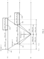
- Figure 4 is a diagram that illustrates how an adaptive random access response window length is determined when a UE does not have access to situation information, in accordance with some embodiments.
- a consistent amount of time may pass along a horizontal axis but be broken up, for ease of explanation, among a first UE, a second UE, and a BS.
- the BS may be configured to receive a Message 1 from the first UE (also noted as UE 1) and the second UE (also noted as UE 2). So that both the Message 1 from the first UE and the second UE is received at the same time, the Message 1 from the first UE may be transmitted at a first time 402 and the Message 1 from the second UE may be transmitted at a second time 404.
- both the message 1s from the first UE and the second UE may arrive at the BS at a third time 406.
- the BS may then transmit a respective Message 2 in response to receipt of the Message 1 from the first UE and the second UE at the third time 406. Accordingly, the respective Message 2 may be received at the second UE at a fourth time 408 and the respective Message 2 may be received at the first UE at a fifth time 410.
- a delay_min may be between the second time 404 and the third time 406 or the third time 406 and the fourth time 408.
- a delay_max may be between the first time 402 and the third time 406 or the third time 406 and the fifth time 410.
- an adapt_RAR_win_len 420A may begin for the first UE after two delay_mins have elapsed (e.g., after a minimum amount of round trip delay) after Message 1 transmission. In this manner, the fifth time 410 may occur during the adapt_RAR_win_len 420A of the first UE.
- an adapt_RAR_win_len 420B for the second UE may also begin after two delay_mins have elapsed (e.g., after a minimum amount of round trip delay) after Message 1 transmission.
- the fourth time 408 may occur during the adapt_RAR_win_len 420B of the second UE.
- the delay_min and delay_max is determined from the broadcast system information of a BS.
- the adapt_RAR_win_len may be determined from the delay_min and delay_max as 2*delay_differential + orig_RAR_win_len, where the delay_differential is the differential between the delay_min and the delay_max and the orig_RAR_win_len is provided in system information.
- a UE has access to situation information that characterizes a location of the UE, an ephemeris of a satellite or a trajectory of a HAPS used by a BS, and a payload type of the satellite or the HAPS used by the BS. Accordingly, the UE may be able to determine the exact amount of propagation delay when the UE does have such situation information.
- the exact amount of propagation delay may be referred to as delay_calc.
- the UE can ignore the aforementioned Options in a system broadcast (e.g., the UE may ignore the broadcast system information to determine the delay_min and/or delay_max).
- the adapt_RAR_win_len may be the orig_RAR_win_len.
- the orig_RAR_win_len may refer to, for example, a predetermined value (e.g., ra -ResponseWindow) defined in certain communication standards.
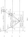
- FIG. 5 is a diagram that illustrates how an adaptive random access response window length is determined when a UE has access to situation information, in accordance with some embodiments.
- a consistent amount of time may pass along a horizontal axis but be broken up, for ease of explanation, among a first UE (also noted as UE 1), a second UE (also noted as UE 2), and a BS.
- the BS may be configured to receive a Message 1 from the first UE and the second UE. So that both the Message 1 from the first UE and the second UE is received at the same time, the Message 1 from the first UE may be transmitted at a first time 502 and the Message 1 from the second UE may be transmitted at a second time 504.
- both the respective message 1s from the first UE and the second UE may arrive at the BS at a third time 506.
- the BS may then transmit a respective Message 2 in response to receipt of the Message 1 from the first UE and the second UE at the third time 506. Accordingly, the respective Message 2 may be received at the second UE at a fourth time 508 and the respective Message 2 may be received at the first UE at a fifth time 510.
- a delay_calc for the second UE may be between the second time 504 and the third time 506 or the third time 506 and the fourth time 508.
- a delay_calc for the first UE e.g., delay_calc, 1
- an adapt_RAR_win_len 520A begins for the first UE after two instances of delay_calc 1 have elapsed (e.g., after a calculated amount of round trip delay) after Message 1 transmission. In this manner, the fifth time 510 may occur during the adapt_RAR_win_len 520A of the first UE.
- an adapt_RAR_win_len 520B for the second UE may also begin after two instances of delay_calc 2 have elapsed (e.g., after a calculated amount of round trip delay) after Message 1 transmission.
- the fourth time 508 may occur during the adapt_RAR_win_len 520B of the second UE.
- the delay_min and delay_max need not be determined from the broadcast system information of a BS when the UE has access to situation information. Rather, the adapt_RAR_win_len may be determined as the orig_RAR_win_len is provided in system information since the delay time specific for the UE may be calculated. Furthermore, in particular embodiments, it can be seen from a comparasion between Figure 4 and Figure 5 that the adapt_RAR_win_len of Option 1 is longer than that of Option 2.
- a UE may additionally determine the adapt_RAR_win_len as outlined in Option 1 when the UE has access to situation information that characterizes a location of the communication device, an ephemeris of the satellite, and a payload type of the satellite.
- the UE may utilize the determination of adapt_RAR_win_len as outlined in Option 1 to guarantee a more reliable random access response monitoring.
- this redundant determination of adapt_RAR_win_len may be applied for UEs that are on vehicles or in other situations for which power consumption (e.g., the available power supply) is not as important (e.g., not as constrained) as other issues such as accuracy.
- this redundant determination of adapt_RAR_win_len may be applied when the UE does not receive a random access response (e.g., Message 2) within its expected adapt_RAR_win_len (e.g., in case the determination of adapt_RAR_win_len in Option 2 was incorrect).
- a random access response e.g., Message 2
- certain UEs may have lower capabilities or limited resources.
- certain more constrained UEs e.g., low cost Internet of Things (IoT) UEs
- IoT Internet of Things
- these more constrained UEs may utilize, for example, a look up table (LUT) to determine values, such as a delay_min, delay_max, or a delay_differential. This LUT may also cover an epheremis.
- LUT look up table
- An example LUT is provided in table 1, below: Table 1 Orbit altitude (km) Payload type Minimum elevation angle (degree) Maximum elevation angle (degree) Delay_max (ms) Delay_min (ms) 35,786 Bentpipe 10 90 270.58 238.57 1,200 Regenerative 10 90 10.44 4
- the more constrained UEs may search the LUT to find an appropriate delay_min, delay_max, or a delay_differential in accordance with the broadcast system information. Since the more constrained UEs may be produced for specific applications (e.g., only for GEO with a given minimum elevation angle), the predetermined or pre-stored LUT may be utilized so that the more constrained UEs may be able to determine the delay_min, delay_max, or delay_differential without actually performing calculations for delay_min, delay_max, or delay_differential. Then, the more constrained UEs may determine their adapt_RAR_win_len in accordance with Case 1.
- a NTN BS may utilize a steering beam. Accordingly, different sets of satellite parameters may be transmitted in the steering beam at different times.
- a first set of satellite parameters referred to as Set A
- Set A may include, for example, an orbit altitude/ephemeris, serving start time, serving duration, and satellite payload type.
- Set A may be broadcast during a first period of time, referred to as Period A.
- a second set of satellite parameters refereed to as Set B, may include, for example, a minimum elevation angle and a maximum elevation angle. This Set B may be broadcast during a second period of time, referred to as Period B.
- Period B may immediately follow Period A.
- Period A and Period B may be of a same amount of time in certain embodiments, or may be of a different amount of time in other embodiments.
- Set A may have static satellite parameter values while Set B may have varying satellite parameter values.
- Period A may be longer than Period B.
- a UE may receive (e.g., listen to) Set A when the UE accesses the NTN BS's network. Then, the UE may receive (e.g., listen to) Set B to track/update the satellite or beam specific parameters after receiving Set A. Accordingly, the UE may determine an appropriate delay_min and delay_max by receiving Set A and Set B from the NTN BS steering beam.
- any reference to an element or embodiment herein using a designation such as "first,” “second,” and so forth does not generally limit the quantity or order of those elements. Rather, these designations can be used herein as a convenient means of distinguishing between two or more elements or instances of an element. Thus, a reference to first and second elements does not mean that only two elements can be employed, or that the first element must precede the second element in some manner.
- any of the various illustrative logical blocks, modules, processors, means, circuits, methods and functions described in connection with the aspects disclosed herein can be implemented by electronic hardware (e.g., a digital implementation, an analog implementation, or a combination of the two), firmware, various forms of program or design code incorporating instructions (which can be referred to herein, for convenience, as "software” or a "software module), or any combination of these techniques.
- electronic hardware e.g., a digital implementation, an analog implementation, or a combination of the two
- firmware various forms of program or design code incorporating instructions
- software or a "software module”
- IC integrated circuit
- DSP digital signal processor
- ASIC application specific integrated circuit
- FPGA field programmable gate array
- the logical blocks, modules, and circuits can further include antennas and/or transceivers to communicate with various components within the network or within the device.
- a general purpose processor can be a microprocessor, but in the alternative, the processor can be any conventional processor, controller, or state machine.
- a processor can also be implemented as a combination of computing devices, e.g., a combination of a DSP and a microprocessor, a plurality of microprocessors, one or more microprocessors in conjunction with a DSP core, or any other suitable configuration to perform the functions described herein.
- Computer-readable media includes both computer storage media and communication media including any medium that can be enabled to transfer a computer program or code from one place to another.
- a storage media can be any available media that can be accessed by a computer.
- such computer-readable media can include RAM, ROM, EEPROM, CD-ROM or other optical disk storage, magnetic disk storage or other magnetic storage devices, or any other medium that can be used to store desired program code in the form of instructions or data structures and that can be accessed by a computer.
- module refers to software, firmware, hardware, and any combination of these elements for performing the associated functions described herein. Additionally, for purpose of discussion, the various modules are described as discrete modules; however, as would be apparent to one of ordinary skill in the art, two or more modules may be combined to form a single module that performs the associated functions according embodiments of the invention.
- one or more of the functions described in this document may be performed by means of computer program code that is stored in a "computer program product”, “computer-readable medium”, and the like, which is used herein to generally refer to media such as, memory storage devices, or storage unit.
- a "computer program product”, “computer-readable medium”, and the like which is used herein to generally refer to media such as, memory storage devices, or storage unit.
- Such instructions may be referred to as "computer program code” (which may be grouped in the form of computer programs or other groupings), which when executed, enable the computing system to perform the desired operations.
- memory or other storage may be employed in embodiments of the invention.
- memory or other storage may be employed in embodiments of the invention.
- any suitable distribution of functionality between different functional units, processing logic elements or domains may be used without detracting from the invention.
- functionality illustrated to be performed by separate processing logic elements, or controllers may be performed by the same processing logic element, or controller.
- references to specific functional units are only references to a suitable means for providing the described functionality, rather than indicative of a strict logical or physical structure or organization.
Landscapes
- Engineering & Computer Science (AREA)
- Computer Networks & Wireless Communication (AREA)
- Signal Processing (AREA)
- Physics & Mathematics (AREA)
- Astronomy & Astrophysics (AREA)
- General Physics & Mathematics (AREA)
- Aviation & Aerospace Engineering (AREA)
- Mobile Radio Communication Systems (AREA)
Claims (6)
- Von einer Kommunikationsvorrichtung durchgeführtes Verfahren, das aufweist:Empfangen von Systeminformationen von einem Kommunikationsknoten, wobei der Kommunikationsknoten unter Verwendung eines Satelliten im Orbit oder einer Plattformstation auf hoher Höhe, HAPS, kommuniziert; undBestimmen des Starts eines Direktzugriff-Antwortfensters und Überwachen auf ein Signal vom Kommunikationsknoten innerhalb des Direktzugriff-Antwortfensters, wobei das Bestimmen des Starts des Direktzugriff-Antwortfensters aufweist:Bestimmen einer minimalen Weiterleitungsverzögerung, delay_min, für die Kommunikation zwischen der Kommunikationsvorrichtung und dem Kommunikationsknoten basierend auf den Systeminformationen; oderBestimmen einer Weiterleitungsverzögerung, delay_calc, für die Kommunikation zwischen der Kommunikationsvorrichtung und dem Kommunikationsknoten basierend auf den Systeminformationen und Situationsinformationen, wobei das Direktzugriffs-Antwortfenster:ab T1+delay_min*2 beginnt, wobei T1 eine Übertragungsendzeit der Message 1 der Kommunikationsvorrichtung ist, wenn die Kommunikationsvorrichtung keinen Zugriff auf Situationsinformationen hat; oderab T1+delay_calc*2 beginnt, wobei T1 eine Übertragungsendzeit der Message 1 der Kommunikationsvorrichtung ist, wenn die Kommunikationsvorrichtung Zugriff auf Situationsinformationen hat, wobei die Situationsinformationen wenigstens eines aufweisen von:einer Position der Kommunikationsvorrichtung,einer Ephemeriden des Satelliten, odereiner Bahn des HAPS, odereinem Payload-Typ des Satelliten oder des HAPS.
- Verfahren nach Anspruch 1, das weiterhin aufweist:
Bestimmen einer maximalen Weiterleitungsverzögerung, delay_max, für die Kommunikation zwischen der Kommunikationsvorrichtung und dem Kommunikationsknoten basierend auf den Systeminformationen. - Verfahren nach Anspruch 1, wobei die Systeminformationen aufweisen:die maximale Weiterleitungsverzögerung und die minimale Weiterleitungsverzögerung; oderdas Zweifache der maximalen Weiterleitungsverzögerung unddas Zweifache der minimalen Weiterleitungsverzögerung; oderdie minimale Weiterleitungsverzögerung und eine Differenz zwischen der minimalen Weiterleitungsverzögerung und der maximalen Weiterleitungsverzögerung; oderdas Zweifache der minimalen Weiterleitungsverzögerung und das Zweifache der Differenz zwischen der minimalen Weiterleitungsverzögerung und der maximalen Weiterleitungsverzögerung.
- Verfahren nach Anspruch 1, wobei die maximale Weiterleitungsverzögerung und die minimale Weiterleitungsverzögerung unter Verwendung einer Lookup-Tabelle basierend auf Systeminformationen und/oder Situationsinformationen bestimmt wird, die aufweisen:eine Höhe des Satelliten oder des HAPS;einen minimalen Höhenwinkel eines Dienststrahls;einen maximalen Höhenwinkel eines Dienststrahls; undeinem Payload-Typ des Satelliten oder des HAPS.
- Kommunikationsvorrichtung, die aufweist:
einen Empfänger, der dazu konfiguriert ist:Systeminformationen von einem Kommunikationsknoten zu empfangen, wobei der Kommunikationsknoten unter Verwendung eines Satelliten im Orbit oder einer Plattformstation auf hoher Höhe, HAPS, kommuniziert; undeinen Prozessor, der dazu konfiguriert ist:
den Start eines Direktzugriff-Antwortfensters zu bestimmen und auf ein Signal vom Kommunikationsknoten innerhalb des Direktzugriff-Antwortfensters zu überwachen, wobei der Prozessor den Start des Direktzugriff-Antwortfensters durch Ausführen eines Prozesses unter Verwendung der Systeminformationen bestimmt, wobei der Prozess aufweist:Bestimmen einer minimalen Weiterleitungsverzögerung, delay_min, für die Kommunikation zwischen der Kommunikationsvorrichtung und dem Kommunikationsknoten, basierend auf den Systeminformationen; oderBestimmen einer Weiterleitungsverzögerung, del_calc, für die Kommunikation zwischen der Kommunikationsvorrichtung und dem Kommunikationsknoten basierend auf den Systeminformationen und den Situationsinformationen, wobei das Direktzugriff-Antwortfenster:ab T1+delay _min*2 beginnt, wobei T1 eine Übertragungsendzeit der Message 1 der Kommunikationsvorrichtung ist, wenn die Kommunikationsvorrichtung keinen Zugriff auf Situationsinformationen hat; oderab T1+delay_calc*2 beginnt, wobei T1 eine Übertragungsendzeit der Message 1 der Kommunikationsvorrichtung ist, wenn die Kommunikationsvorrichtung Zugriff auf Situationsinformationen hat, wobei die Situationsinformationen wenigstens eines aufweisen von:einer Position der Kommunikationsvorrichtung,einer Ephemeriden des Satelliten, odereiner Bahn des HAPS, odereinen Payload-Typen des Satelliten oder des HAPS; - Kommunikationsvorrichtung nach Anspruch 5, wobei die Systeminformationen wenigstens aufweisen:eine maximale Weiterleitungsverzögerung und eine minimale Weiterleitungsverzögerung; oderdas Zweifache der maximalen Weiterleitungsverzögerung und das Zweifache der minimalen Weiterleitungsverzögerung; oderdie minimale Weiterleitungsverzögerung und eine Differenz zwischen der minimalen Weiterleitungsverzögerung und der maximalen Weiterleitungsverzögerung; oderdas Zweifache der minimalen Weiterleitungsverzögerung und das Zweifache der Differenz zwischen der minimalen Weiterleitungsverzögerung und der maximalen Weiterleitungsverzögerung; odereine Höhe des Satelliten oder des HAPS; odereine Dienststartzeit; odereine Dienstdauer; odereinen minimalen Höhenwinkel eines Dienststrahls; odereinen maximalen Höhenwinkel eines Dienststrahls.
Applications Claiming Priority (1)
| Application Number | Priority Date | Filing Date | Title |
|---|---|---|---|
| PCT/CN2019/072171 WO2020034581A1 (en) | 2019-01-17 | 2019-01-17 | Adaptive random access response window |
Publications (3)
| Publication Number | Publication Date |
|---|---|
| EP3912418A1 EP3912418A1 (de) | 2021-11-24 |
| EP3912418A4 EP3912418A4 (de) | 2022-08-10 |
| EP3912418B1 true EP3912418B1 (de) | 2025-04-09 |
Family
ID=69525000
Family Applications (1)
| Application Number | Title | Priority Date | Filing Date |
|---|---|---|---|
| EP19850593.5A Active EP3912418B1 (de) | 2019-01-17 | 2019-01-17 | Adaptives direktzugriffsantwortfenster |
Country Status (5)
| Country | Link |
|---|---|
| US (1) | US11937293B2 (de) |
| EP (1) | EP3912418B1 (de) |
| KR (1) | KR102733905B1 (de) |
| CN (1) | CN113228796B (de) |
| WO (1) | WO2020034581A1 (de) |
Families Citing this family (7)
| Publication number | Priority date | Publication date | Assignee | Title |
|---|---|---|---|---|
| CN110545138B (zh) * | 2019-09-29 | 2024-05-10 | 中兴通讯股份有限公司 | 一种信息指示方法、装置及计算机可读存储介质 |
| US20230261737A1 (en) * | 2020-07-02 | 2023-08-17 | Eutelsat S A | Methods for the transmission of data between a resource constrained device and a non-geostationary satellite and associated method |
| CN114071691B (zh) * | 2020-08-07 | 2023-07-21 | 北京佰才邦技术股份有限公司 | 随机接入响应检测方法、装置、终端及基站侧设备 |
| CN114257288B (zh) * | 2020-09-25 | 2023-05-09 | 展讯半导体(南京)有限公司 | 等待时长确定方法及装置 |
| US11751253B2 (en) * | 2021-02-25 | 2023-09-05 | Lockheed Martin Corporation | Random access for broadband 4G and 5G over satellite |
| WO2023050393A1 (zh) * | 2021-09-30 | 2023-04-06 | 北京小米移动软件有限公司 | 一种随机接入响应窗口的确定方法及其装置 |
| US12490265B2 (en) * | 2022-10-26 | 2025-12-02 | Qualcomm Incorporated | Resource efficient common search space monitoring |
Family Cites Families (15)
| Publication number | Priority date | Publication date | Assignee | Title |
|---|---|---|---|---|
| US20110243075A1 (en) * | 2009-06-16 | 2011-10-06 | Qualcomm Incorporated | Method and apparatus for access procedure in a wireless communication system |
| EP2659721B1 (de) * | 2010-12-30 | 2014-10-15 | Telefonaktiebolaget LM Ericsson (PUBL) | Zeitliche steuerung einer signalübertragung in aufwärtsrichtung |
| US8395985B2 (en) * | 2011-07-25 | 2013-03-12 | Ofinno Technologies, Llc | Time alignment in multicarrier OFDM network |
| CN104412676B (zh) * | 2012-06-26 | 2018-11-16 | Lg电子株式会社 | 无线通信系统中的d2d通信的同步方法和同步设备 |
| EP3105981B1 (de) * | 2014-02-10 | 2019-11-20 | Telefonaktiebolaget LM Ericsson (publ) | Verfahren und vorrichtungen für direktzugriffspräambelwechsel |
| EP3562249B1 (de) * | 2014-08-15 | 2024-07-24 | InterDigital Patent Holdings, Inc. | Unterstützung von zufallszugriff und funkruf für wtrus mit verringerter kapazität in einem lte-system |
| US9918344B2 (en) * | 2015-04-09 | 2018-03-13 | Intel IP Corporation | Random access procedure for enhanced coverage support |
| US9743426B2 (en) * | 2015-04-19 | 2017-08-22 | Alcatel Lucent | Dynamic determination and signaling of a RAR window size to a coverage enhanced low complexity machine type communication device |
| EP3157282A1 (de) * | 2015-10-16 | 2017-04-19 | Panasonic Intellectual Property Corporation of America | Verbesserte uplink-übertragungen in unlizenzierten zellen mit zusätzlichen übertragungszeitoffsets |
| US10236933B2 (en) * | 2016-10-07 | 2019-03-19 | Qualcomm Incorporated | Timing offset compensation for inter-link interference cancellation |
| CN109152027B (zh) * | 2017-06-16 | 2023-09-29 | 华为技术有限公司 | 通信方法及装置 |
| CN109219147A (zh) * | 2017-07-05 | 2019-01-15 | 普天信息技术有限公司 | 一种随机接入响应方法与基站 |
| US11394459B2 (en) * | 2017-11-16 | 2022-07-19 | Sony Corporation | Terminal device, base station device, and method |
| GB2572336B (en) * | 2018-03-26 | 2022-02-02 | Samsung Electronics Co Ltd | Improvements in and relating to random access in a telecommunication network |
| EP3777438B1 (de) * | 2018-04-03 | 2023-10-11 | InterDigital Patent Holdings, Inc. | Zeitvorlauf für nicht terrestrische netzwerkkommunikation |
-
2019
- 2019-01-17 EP EP19850593.5A patent/EP3912418B1/de active Active
- 2019-01-17 WO PCT/CN2019/072171 patent/WO2020034581A1/en not_active Ceased
- 2019-01-17 CN CN201980084593.5A patent/CN113228796B/zh active Active
- 2019-01-17 KR KR1020217026083A patent/KR102733905B1/ko active Active
-
2021
- 2021-07-16 US US17/377,928 patent/US11937293B2/en active Active
Also Published As
| Publication number | Publication date |
|---|---|
| CN113228796B (zh) | 2024-08-02 |
| CN113228796A (zh) | 2021-08-06 |
| WO2020034581A1 (en) | 2020-02-20 |
| US20210345398A1 (en) | 2021-11-04 |
| EP3912418A4 (de) | 2022-08-10 |
| KR102733905B1 (ko) | 2024-11-25 |
| KR20210116574A (ko) | 2021-09-27 |
| EP3912418A1 (de) | 2021-11-24 |
| US11937293B2 (en) | 2024-03-19 |
Similar Documents
| Publication | Publication Date | Title |
|---|---|---|
| US11937293B2 (en) | Adaptive random access response window | |
| US11973571B2 (en) | Systems and methods for determining communication parameters for non terrestrial networks | |
| US12302130B2 (en) | System and method for providing configuration information | |
| US20230261838A1 (en) | System and method for synchronization assistance | |
| CN114830817A (zh) | 一种定时提前更新方法、终端设备、网络设备 | |
| US12580685B2 (en) | Determining number of repetition transmissions for data transmission based on repetition transmission number information | |
| EP3979727A1 (de) | Drahtloskommunikationsverfahren, endgerätevorrichtung und netzwerkvorrichtung | |
| US20210037452A1 (en) | System information for cell selection/reselection by an aerial ue | |
| US20240031077A1 (en) | Methods, devices and systems for harq feedback disabling | |
| WO2024108921A1 (en) | Systems and methods for timing enhancement in store and forward mode | |
| US12538311B2 (en) | System and method for transmission indications | |
| US20250047369A1 (en) | Satellite communication method and apparatus | |
| US20250267429A1 (en) | Systems and methods for global navigation satellite system (gnss) related information indication | |
| WO2025130078A1 (en) | Uplink and downlink scheduling for wireless communication systems | |
| AU2022485564B2 (en) | Systems and methods for extending validation duration | |
| KR20220112801A (ko) | Prach 리소스 구성을 위한 시스템 및 방법 | |
| JP2025528334A (ja) | 非地上波ネットワークにおけるカバレッジ拡張のためのシステムおよび方法 | |
| WO2025156410A1 (en) | Systems and methods for common signal/channel reception | |
| US20240357659A1 (en) | Systems and methods for enhanced random access procedure | |
| WO2025091258A1 (en) | Systems and methods for synchronization signal block enhancement |
Legal Events
| Date | Code | Title | Description |
|---|---|---|---|
| STAA | Information on the status of an ep patent application or granted ep patent |
Free format text: STATUS: THE INTERNATIONAL PUBLICATION HAS BEEN MADE |
|
| PUAI | Public reference made under article 153(3) epc to a published international application that has entered the european phase |
Free format text: ORIGINAL CODE: 0009012 |
|
| STAA | Information on the status of an ep patent application or granted ep patent |
Free format text: STATUS: REQUEST FOR EXAMINATION WAS MADE |
|
| 17P | Request for examination filed |
Effective date: 20210817 |
|
| AK | Designated contracting states |
Kind code of ref document: A1 Designated state(s): AL AT BE BG CH CY CZ DE DK EE ES FI FR GB GR HR HU IE IS IT LI LT LU LV MC MK MT NL NO PL PT RO RS SE SI SK SM TR |
|
| DAV | Request for validation of the european patent (deleted) | ||
| DAX | Request for extension of the european patent (deleted) | ||
| A4 | Supplementary search report drawn up and despatched |
Effective date: 20220711 |
|
| RIC1 | Information provided on ipc code assigned before grant |
Ipc: H04W 74/08 20090101ALN20220705BHEP Ipc: H04B 7/185 20060101ALN20220705BHEP Ipc: H04W 74/00 20090101AFI20220705BHEP |
|
| REG | Reference to a national code |
Ref country code: DE Free format text: PREVIOUS MAIN CLASS: H04W0072100000 Ref country code: DE Ref legal event code: R079 Ref document number: 602019068525 Country of ref document: DE Free format text: PREVIOUS MAIN CLASS: H04W0072100000 Ipc: H04W0074083300 |
|
| GRAP | Despatch of communication of intention to grant a patent |
Free format text: ORIGINAL CODE: EPIDOSNIGR1 |
|
| STAA | Information on the status of an ep patent application or granted ep patent |
Free format text: STATUS: GRANT OF PATENT IS INTENDED |
|
| RIC1 | Information provided on ipc code assigned before grant |
Ipc: H04B 7/185 20060101ALN20241205BHEP Ipc: H04W 74/00 20090101ALN20241205BHEP Ipc: H04W 56/00 20090101ALI20241205BHEP Ipc: H04W 48/08 20090101ALI20241205BHEP Ipc: H04W 74/0833 20240101AFI20241205BHEP |
|
| INTG | Intention to grant announced |
Effective date: 20241213 |
|
| GRAS | Grant fee paid |
Free format text: ORIGINAL CODE: EPIDOSNIGR3 |
|
| GRAA | (expected) grant |
Free format text: ORIGINAL CODE: 0009210 |
|
| STAA | Information on the status of an ep patent application or granted ep patent |
Free format text: STATUS: THE PATENT HAS BEEN GRANTED |
|
| AK | Designated contracting states |
Kind code of ref document: B1 Designated state(s): AL AT BE BG CH CY CZ DE DK EE ES FI FR GB GR HR HU IE IS IT LI LT LU LV MC MK MT NL NO PL PT RO RS SE SI SK SM TR |
|
| REG | Reference to a national code |
Ref country code: GB Ref legal event code: FG4D |
|
| REG | Reference to a national code |
Ref country code: CH Ref legal event code: EP |
|
| REG | Reference to a national code |
Ref country code: DE Ref legal event code: R096 Ref document number: 602019068525 Country of ref document: DE |
|
| REG | Reference to a national code |
Ref country code: IE Ref legal event code: FG4D |
|
| REG | Reference to a national code |
Ref country code: NL Ref legal event code: FP |
|
| REG | Reference to a national code |
Ref country code: SE Ref legal event code: TRGR |
|
| REG | Reference to a national code |
Ref country code: AT Ref legal event code: MK05 Ref document number: 1784781 Country of ref document: AT Kind code of ref document: T Effective date: 20250409 |
|
| PG25 | Lapsed in a contracting state [announced via postgrant information from national office to epo] |
Ref country code: FI Free format text: LAPSE BECAUSE OF FAILURE TO SUBMIT A TRANSLATION OF THE DESCRIPTION OR TO PAY THE FEE WITHIN THE PRESCRIBED TIME-LIMIT Effective date: 20250409 Ref country code: PT Free format text: LAPSE BECAUSE OF FAILURE TO SUBMIT A TRANSLATION OF THE DESCRIPTION OR TO PAY THE FEE WITHIN THE PRESCRIBED TIME-LIMIT Effective date: 20250811 Ref country code: ES Free format text: LAPSE BECAUSE OF FAILURE TO SUBMIT A TRANSLATION OF THE DESCRIPTION OR TO PAY THE FEE WITHIN THE PRESCRIBED TIME-LIMIT Effective date: 20250409 |
|
| REG | Reference to a national code |
Ref country code: LT Ref legal event code: MG9D |
|
| PG25 | Lapsed in a contracting state [announced via postgrant information from national office to epo] |
Ref country code: GR Free format text: LAPSE BECAUSE OF FAILURE TO SUBMIT A TRANSLATION OF THE DESCRIPTION OR TO PAY THE FEE WITHIN THE PRESCRIBED TIME-LIMIT Effective date: 20250710 Ref country code: NO Free format text: LAPSE BECAUSE OF FAILURE TO SUBMIT A TRANSLATION OF THE DESCRIPTION OR TO PAY THE FEE WITHIN THE PRESCRIBED TIME-LIMIT Effective date: 20250709 |
|
| PG25 | Lapsed in a contracting state [announced via postgrant information from national office to epo] |
Ref country code: PL Free format text: LAPSE BECAUSE OF FAILURE TO SUBMIT A TRANSLATION OF THE DESCRIPTION OR TO PAY THE FEE WITHIN THE PRESCRIBED TIME-LIMIT Effective date: 20250409 |
|
| PG25 | Lapsed in a contracting state [announced via postgrant information from national office to epo] |
Ref country code: BG Free format text: LAPSE BECAUSE OF FAILURE TO SUBMIT A TRANSLATION OF THE DESCRIPTION OR TO PAY THE FEE WITHIN THE PRESCRIBED TIME-LIMIT Effective date: 20250409 |
|
| PG25 | Lapsed in a contracting state [announced via postgrant information from national office to epo] |
Ref country code: HR Free format text: LAPSE BECAUSE OF FAILURE TO SUBMIT A TRANSLATION OF THE DESCRIPTION OR TO PAY THE FEE WITHIN THE PRESCRIBED TIME-LIMIT Effective date: 20250409 |
|
| PG25 | Lapsed in a contracting state [announced via postgrant information from national office to epo] |
Ref country code: AT Free format text: LAPSE BECAUSE OF FAILURE TO SUBMIT A TRANSLATION OF THE DESCRIPTION OR TO PAY THE FEE WITHIN THE PRESCRIBED TIME-LIMIT Effective date: 20250409 |
|
| PG25 | Lapsed in a contracting state [announced via postgrant information from national office to epo] |
Ref country code: RS Free format text: LAPSE BECAUSE OF FAILURE TO SUBMIT A TRANSLATION OF THE DESCRIPTION OR TO PAY THE FEE WITHIN THE PRESCRIBED TIME-LIMIT Effective date: 20250709 |
|
| PG25 | Lapsed in a contracting state [announced via postgrant information from national office to epo] |
Ref country code: IS Free format text: LAPSE BECAUSE OF FAILURE TO SUBMIT A TRANSLATION OF THE DESCRIPTION OR TO PAY THE FEE WITHIN THE PRESCRIBED TIME-LIMIT Effective date: 20250809 |
|
| PG25 | Lapsed in a contracting state [announced via postgrant information from national office to epo] |
Ref country code: LV Free format text: LAPSE BECAUSE OF FAILURE TO SUBMIT A TRANSLATION OF THE DESCRIPTION OR TO PAY THE FEE WITHIN THE PRESCRIBED TIME-LIMIT Effective date: 20250409 |
|
| PGFP | Annual fee paid to national office [announced via postgrant information from national office to epo] |
Ref country code: GB Payment date: 20251204 Year of fee payment: 8 |
|
| REG | Reference to a national code |
Ref country code: DE Ref legal event code: R097 Ref document number: 602019068525 Country of ref document: DE |
|
| PG25 | Lapsed in a contracting state [announced via postgrant information from national office to epo] |
Ref country code: DK Free format text: LAPSE BECAUSE OF FAILURE TO SUBMIT A TRANSLATION OF THE DESCRIPTION OR TO PAY THE FEE WITHIN THE PRESCRIBED TIME-LIMIT Effective date: 20250409 Ref country code: SM Free format text: LAPSE BECAUSE OF FAILURE TO SUBMIT A TRANSLATION OF THE DESCRIPTION OR TO PAY THE FEE WITHIN THE PRESCRIBED TIME-LIMIT Effective date: 20250409 |
|
| PGFP | Annual fee paid to national office [announced via postgrant information from national office to epo] |
Ref country code: NL Payment date: 20251215 Year of fee payment: 8 Ref country code: FR Payment date: 20251208 Year of fee payment: 8 |
|
| PGFP | Annual fee paid to national office [announced via postgrant information from national office to epo] |
Ref country code: SE Payment date: 20251210 Year of fee payment: 8 |
|
| PG25 | Lapsed in a contracting state [announced via postgrant information from national office to epo] |
Ref country code: CZ Free format text: LAPSE BECAUSE OF FAILURE TO SUBMIT A TRANSLATION OF THE DESCRIPTION OR TO PAY THE FEE WITHIN THE PRESCRIBED TIME-LIMIT Effective date: 20250409 |
|
| PG25 | Lapsed in a contracting state [announced via postgrant information from national office to epo] |
Ref country code: EE Free format text: LAPSE BECAUSE OF FAILURE TO SUBMIT A TRANSLATION OF THE DESCRIPTION OR TO PAY THE FEE WITHIN THE PRESCRIBED TIME-LIMIT Effective date: 20250409 |
|
| PG25 | Lapsed in a contracting state [announced via postgrant information from national office to epo] |
Ref country code: RO Free format text: LAPSE BECAUSE OF FAILURE TO SUBMIT A TRANSLATION OF THE DESCRIPTION OR TO PAY THE FEE WITHIN THE PRESCRIBED TIME-LIMIT Effective date: 20250409 Ref country code: SK Free format text: LAPSE BECAUSE OF FAILURE TO SUBMIT A TRANSLATION OF THE DESCRIPTION OR TO PAY THE FEE WITHIN THE PRESCRIBED TIME-LIMIT Effective date: 20250409 |
|
| PG25 | Lapsed in a contracting state [announced via postgrant information from national office to epo] |
Ref country code: IT Free format text: LAPSE BECAUSE OF FAILURE TO SUBMIT A TRANSLATION OF THE DESCRIPTION OR TO PAY THE FEE WITHIN THE PRESCRIBED TIME-LIMIT Effective date: 20250409 |
|
| PLBE | No opposition filed within time limit |
Free format text: ORIGINAL CODE: 0009261 |
|
| STAA | Information on the status of an ep patent application or granted ep patent |
Free format text: STATUS: NO OPPOSITION FILED WITHIN TIME LIMIT |
|
| REG | Reference to a national code |
Ref country code: CH Ref legal event code: L10 Free format text: ST27 STATUS EVENT CODE: U-0-0-L10-L00 (AS PROVIDED BY THE NATIONAL OFFICE) Effective date: 20260218 |
|
| 26N | No opposition filed |
Effective date: 20260112 |
|
| PGFP | Annual fee paid to national office [announced via postgrant information from national office to epo] |
Ref country code: DE Payment date: 20251203 Year of fee payment: 8 |