EP3911864B1 - A dampened bearing component, bearing including said component, and rotary machine including said bearing - Google Patents
A dampened bearing component, bearing including said component, and rotary machine including said bearing Download PDFInfo
- Publication number
- EP3911864B1 EP3911864B1 EP20700863.2A EP20700863A EP3911864B1 EP 3911864 B1 EP3911864 B1 EP 3911864B1 EP 20700863 A EP20700863 A EP 20700863A EP 3911864 B1 EP3911864 B1 EP 3911864B1
- Authority
- EP
- European Patent Office
- Prior art keywords
- bearing
- cylindrical member
- external cylindrical
- component
- internal cylindrical
- Prior art date
- Legal status (The legal status is an assumption and is not a legal conclusion. Google has not performed a legal analysis and makes no representation as to the accuracy of the status listed.)
- Active
Links
Images



Classifications
-
- F—MECHANICAL ENGINEERING; LIGHTING; HEATING; WEAPONS; BLASTING
- F16—ENGINEERING ELEMENTS AND UNITS; GENERAL MEASURES FOR PRODUCING AND MAINTAINING EFFECTIVE FUNCTIONING OF MACHINES OR INSTALLATIONS; THERMAL INSULATION IN GENERAL
- F16C—SHAFTS; FLEXIBLE SHAFTS; ELEMENTS OR CRANKSHAFT MECHANISMS; ROTARY BODIES OTHER THAN GEARING ELEMENTS; BEARINGS
- F16C27/00—Elastic or yielding bearings or bearing supports, for exclusively rotary movement
- F16C27/02—Sliding-contact bearings
-
- F—MECHANICAL ENGINEERING; LIGHTING; HEATING; WEAPONS; BLASTING
- F04—POSITIVE - DISPLACEMENT MACHINES FOR LIQUIDS; PUMPS FOR LIQUIDS OR ELASTIC FLUIDS
- F04D—NON-POSITIVE-DISPLACEMENT PUMPS
- F04D29/00—Details, component parts, or accessories
- F04D29/04—Shafts or bearings, or assemblies thereof
- F04D29/046—Bearings
-
- F—MECHANICAL ENGINEERING; LIGHTING; HEATING; WEAPONS; BLASTING
- F04—POSITIVE - DISPLACEMENT MACHINES FOR LIQUIDS; PUMPS FOR LIQUIDS OR ELASTIC FLUIDS
- F04D—NON-POSITIVE-DISPLACEMENT PUMPS
- F04D29/00—Details, component parts, or accessories
- F04D29/04—Shafts or bearings, or assemblies thereof
- F04D29/046—Bearings
- F04D29/047—Bearings hydrostatic; hydrodynamic
- F04D29/0476—Bearings hydrostatic; hydrodynamic for axial pumps
-
- F—MECHANICAL ENGINEERING; LIGHTING; HEATING; WEAPONS; BLASTING
- F04—POSITIVE - DISPLACEMENT MACHINES FOR LIQUIDS; PUMPS FOR LIQUIDS OR ELASTIC FLUIDS
- F04D—NON-POSITIVE-DISPLACEMENT PUMPS
- F04D29/00—Details, component parts, or accessories
- F04D29/66—Combating cavitation, whirls, noise, vibration or the like; Balancing
- F04D29/669—Combating cavitation, whirls, noise, vibration or the like; Balancing especially adapted for liquid pumps
-
- F—MECHANICAL ENGINEERING; LIGHTING; HEATING; WEAPONS; BLASTING
- F04—POSITIVE - DISPLACEMENT MACHINES FOR LIQUIDS; PUMPS FOR LIQUIDS OR ELASTIC FLUIDS
- F04D—NON-POSITIVE-DISPLACEMENT PUMPS
- F04D31/00—Pumping liquids and elastic fluids at the same time
-
- F—MECHANICAL ENGINEERING; LIGHTING; HEATING; WEAPONS; BLASTING
- F16—ENGINEERING ELEMENTS AND UNITS; GENERAL MEASURES FOR PRODUCING AND MAINTAINING EFFECTIVE FUNCTIONING OF MACHINES OR INSTALLATIONS; THERMAL INSULATION IN GENERAL
- F16C—SHAFTS; FLEXIBLE SHAFTS; ELEMENTS OR CRANKSHAFT MECHANISMS; ROTARY BODIES OTHER THAN GEARING ELEMENTS; BEARINGS
- F16C17/00—Sliding-contact bearings for exclusively rotary movement
- F16C17/02—Sliding-contact bearings for exclusively rotary movement for radial load only
-
- F—MECHANICAL ENGINEERING; LIGHTING; HEATING; WEAPONS; BLASTING
- F16—ENGINEERING ELEMENTS AND UNITS; GENERAL MEASURES FOR PRODUCING AND MAINTAINING EFFECTIVE FUNCTIONING OF MACHINES OR INSTALLATIONS; THERMAL INSULATION IN GENERAL
- F16C—SHAFTS; FLEXIBLE SHAFTS; ELEMENTS OR CRANKSHAFT MECHANISMS; ROTARY BODIES OTHER THAN GEARING ELEMENTS; BEARINGS
- F16C17/00—Sliding-contact bearings for exclusively rotary movement
- F16C17/02—Sliding-contact bearings for exclusively rotary movement for radial load only
- F16C17/024—Sliding-contact bearings for exclusively rotary movement for radial load only with flexible leaves to create hydrodynamic wedge, e.g. radial foil bearings
-
- F—MECHANICAL ENGINEERING; LIGHTING; HEATING; WEAPONS; BLASTING
- F16—ENGINEERING ELEMENTS AND UNITS; GENERAL MEASURES FOR PRODUCING AND MAINTAINING EFFECTIVE FUNCTIONING OF MACHINES OR INSTALLATIONS; THERMAL INSULATION IN GENERAL
- F16C—SHAFTS; FLEXIBLE SHAFTS; ELEMENTS OR CRANKSHAFT MECHANISMS; ROTARY BODIES OTHER THAN GEARING ELEMENTS; BEARINGS
- F16C17/00—Sliding-contact bearings for exclusively rotary movement
- F16C17/10—Sliding-contact bearings for exclusively rotary movement for both radial and axial load
-
- F—MECHANICAL ENGINEERING; LIGHTING; HEATING; WEAPONS; BLASTING
- F16—ENGINEERING ELEMENTS AND UNITS; GENERAL MEASURES FOR PRODUCING AND MAINTAINING EFFECTIVE FUNCTIONING OF MACHINES OR INSTALLATIONS; THERMAL INSULATION IN GENERAL
- F16C—SHAFTS; FLEXIBLE SHAFTS; ELEMENTS OR CRANKSHAFT MECHANISMS; ROTARY BODIES OTHER THAN GEARING ELEMENTS; BEARINGS
- F16C27/00—Elastic or yielding bearings or bearing supports, for exclusively rotary movement
- F16C27/06—Elastic or yielding bearings or bearing supports, for exclusively rotary movement by means of parts of rubber or like materials
- F16C27/063—Sliding contact bearings
-
- F—MECHANICAL ENGINEERING; LIGHTING; HEATING; WEAPONS; BLASTING
- F16—ENGINEERING ELEMENTS AND UNITS; GENERAL MEASURES FOR PRODUCING AND MAINTAINING EFFECTIVE FUNCTIONING OF MACHINES OR INSTALLATIONS; THERMAL INSULATION IN GENERAL
- F16C—SHAFTS; FLEXIBLE SHAFTS; ELEMENTS OR CRANKSHAFT MECHANISMS; ROTARY BODIES OTHER THAN GEARING ELEMENTS; BEARINGS
- F16C33/00—Parts of bearings; Special methods for making bearings or parts thereof
- F16C33/02—Parts of sliding-contact bearings
- F16C33/04—Brasses; Bushes; Linings
- F16C33/26—Brasses; Bushes; Linings made from wire coils; made from a number of discs, rings, rods, or other members
-
- F—MECHANICAL ENGINEERING; LIGHTING; HEATING; WEAPONS; BLASTING
- F16—ENGINEERING ELEMENTS AND UNITS; GENERAL MEASURES FOR PRODUCING AND MAINTAINING EFFECTIVE FUNCTIONING OF MACHINES OR INSTALLATIONS; THERMAL INSULATION IN GENERAL
- F16C—SHAFTS; FLEXIBLE SHAFTS; ELEMENTS OR CRANKSHAFT MECHANISMS; ROTARY BODIES OTHER THAN GEARING ELEMENTS; BEARINGS
- F16C2360/00—Engines or pumps
- F16C2360/44—Centrifugal pumps
Definitions
- Embodiments disclosed herein concern improvements to bearings and components thereof specifically intended for rotatingly supporting impellers of rotodynamic pumps, such as multi-phase pumps.
- GB988200A discloses a bearing for a rotating shaft.
- US1370599A discloses a resilient support for machinery according to the preamble of claim 1.
- US5209577A discloses a downhole rotating machine.
- EP2899414A1 discloses a bearing of a rotor shaft.
- DE19701178A1 discloses bearing ring shells.
- US3318642A discloses a self-aligning bearing.
- US2018/087516A1 discloses a turbomachine with active magnetic bearings.
- Rotodynamic pumps are used in a variety of applications for transferring energy to a process fluid by means of one or more rotating impeller.
- dynamic pumps or rotodynamic pumps are machines wherein a fluid is pressurized by transferring kinetic energy, typically from a rotating element such as an impeller, to the fluid being processed through the pump.
- Some pumps are designed for processing a multi-phase fluid, containing a liquid and a gaseous phase.
- Some pumps include embedded electric motors, which rotate each impeller and which can be adapted to control the rotational speed of each impeller independently of the other impellers of the pump, for instance in order to adapt the rotational speed to the actual gas/liquid ratio in each pump stage.
- Embodiments of multi-phase pumps with embedded electric motors are disclosed for instance in US2017/0159665 .
- PCD polycrystalline diamond
- impellers as well as other rotary machine components, can generate vibrations. These vibrations are transmitted through the bearings to the stationary structure and may propagate from one impeller to other impellers or other machine parts, and may damage the machine.
- PCD bearings are particularly rigid and have a small coefficient of friction. These features are beneficial in many applications. However, stiffness of the bearing results in strong vibration propagations from the rotary components to the stationary components of the machine.
- a bearing comprises an external cylindrical member having an outer bearing surface and an inner cavity, and an internal cylindrical member, arranged in the inner cavity of the external cylindrical member and substantially coaxial thereto.
- the external cylindrical member and the internal cylindrical member form a gap therebetween.
- a resilient damping feature is arranged in the gap.
- the bearing further comprises bearing pads on the outer bearing surface of the external cylindrical member and wherein the outer bearing component has an inner cylindrical bearing surface provided with a plurality of bearing pads arranged to co-act with the bearing pads on the outer bearing surface of the inner bearing component.
- the resilient damping feature can include a corrugated laminar member or sheet.
- the resilient damping feature reduces the transmission of vibrations from a rotating member, such as an impeller, to a stationery member, such as a supporting shaft of a rotodynamic pump or other rotary machine.
- a novel and useful bearing structure has been developed, to improve the dynamic behavior of bearings, such as in particular, but not exclusively, PCD bearings and other bearings characterized by high stiffness.
- the novel bearings include two components, arranged coaxial to one another. One component rotates integrally with a rotary machine part, such as an impeller of a rotodynamic pump. The other component is stationarily housed in the machine housing.
- the stationary component includes damping features, which prevent or reduce the propagation of vibrations between the rotary machine component and the stationary structure of the machine.
- the stationary component of the bearing includes two co-axial substantially cylindrical members, namely an internal one and an external one.
- the internal and external members form a gap therebetween.
- a resilient damping feature is arranged, which is adapted to allow dampened displacements of the external cylindrical member with respect to the internal cylindrical member.
- Displacements can be in a radial direction and/or in a tangential direction.
- Displacements can be provoked by vibrations of a rotary machine component, mounted for integral rotation with the external bearing component.
- the vibrations propagate through bearing pads from the outer component to the inner component and are dampened by the resilient damping feature arranged in the gap formed in the inner component, between the external cylindrical member and the internal cylindrical member thereof. This results in efficient damping of vibrations and reduced propagation of the vibrations generated by the rotary machine component towards the stationary structure of the machine.
- a rotodynamic pump 1 comprises a casing 3 and a stationary shaft 5 arranged therein.
- the stationary shaft can be formed by a beam extending longitudinally through the pump casing.
- the stationary shaft 5 can be comprised of stacked shaft sections connected to one another by an axial tie rod.
- the pump can comprise a plurality of stages 7. Each pump stage 7 comprises a respective impeller 9, which is supported for rotation on the shaft 5 and coacts with a statoric part 11, i.e. with a non-rotating, stationary component of the pump 1. If the stationary shaft 5 is formed by stacked sections, each impeller 9 can be supported by a separate section of the stationary shaft 5.
- each impeller 9 comprises a disc-shaped body 12 and a plurality of blades 13 distributed annularly around a rotation axis A-A.
- a process fluid path 15 extends across the bladed portion of each impeller 9. Mechanical power generated by embedded electric motors, to be described, rotate the impellers 9, which transfer the power to the process fluid along the process fluid path 15 to boost the pressure of the fluid.
- each impeller 9 comprises a shroud 17.
- Each impeller 9 is driven into rotation by a respective electric motor 18 housed in the casing 3.
- Each electric motor 18 includes a rotor 19, arranged around the shroud 17 and rotating with the impeller 9, as well as a stator 21 developing around the rotor 19 and stationarily housed in the casing 3.
- each impeller 9 is supported on the stationary shaft 5 by means of a respective bearing 31.
- each bearing 31 comprises a stationary inner bearing component 31B and an outer rotary bearing component 31A.
- the two components 31A, 31B are substantially co-axial.
- the bearing 31 is a PCD (PolyCrystalline Diamond) bearing comprised of radial bearing pads 51A on the rotary outer bearing component 31A and radial bearing pads 51B on the stationary inner component 31B.
- Each bearing 31 can further include axial bearing pads 53A on the rotary outer bearing component 31A and axial bearing pads 53B on the stationary inner bearing component 31B or on the statoric part 11 of the pump 1.
- the inner bearing component 31B is configured to provide a vibration damping effect, such that vibrations generated by the rotating impeller 9, for instance, are dampened and not propagated, or propagated only in a dampened manner, through the respective bearing 31 towards the stationary structure 11 of the pump 1.
- the inner stationary bearing component 31B comprises an external cylindrical member 61 and an internal cylindrical member 63.
- the internal and external cylindrical members 61, 63 are substantially co-axial to one another and to the stationary shaft 5, on which the internal cylindrical member 63 can be mounted.
- the bearing pads 51B are integral with the external cylindrical member 61.
- the external cylindrical member 61 and the internal cylindrical member 63 can be coupled to one another by a ferrule 65, see Fig.2 , which can be screwed on one end of the internal cylindrical member 63.
- the opposite end of the internal cylindrical member 63 can form a flange 67.
- the external cylindrical member 61 can be pressed by screwing the ferrule 65, between the flange 67 and the ferrule 65.
- O-ring or similar seals 71, 73 can be arranged between the internal cylindrical member 63 and the external cylindrical member 61.
- a cylindrical gap 75 is formed between the external cylindrical member 61 and the internal cylindrical member 63.
- the cylindrical gap 75 extends in an axial direction, i.e. parallel to the rotation axis A-A.
- a resilient damping feature is arranged in the cylindrical gap 75 .
- the term "resilient damping feature” can be understood as any mechanical device or combination of devices arranged between the external cylindrical member 61 and the internal cylindrical member 63 and co-acting therewith, such that the vibration of one said internal and external cylindrical members 63, 61 is not transmitted to the other of said internal and external cylindrical members 63, 61, or a dampened vibration is transmitted thereto.
- a lubricant fluid preferably a lubricant liquid, such as oil or other preferably high-viscosity fluid can fill the gap 75.
- the resilient damping feature includes a corrugated tubular sheet 77.
- the corrugated tubular sheet 77 comprises corrugations 77A extending axially, i.e. parallel to the rotation axis A-A of the bearing 31. Due to the corrugated tubular sheet 77 arranged in the gap 75, the external cylindrical member 61 and the internal cylindrical member 63 can move one with respect to the other to a limited extent in a radial direction, for instance due to oscillations induced by vibrations of the rotary impeller 9. The radial displacement of the external cylindrical member 61 with respect to the internal cylindrical member 63 is obtained through the compliance of the corrugations 77A under a radial load applied thereto. The oscillation in radial direction is dampened by the resilient damping feature, provided by the corrugated tubular sheet 77.
- the external cylindrical member 61 can also move tangentially with respect to the internal cylindrical member 63, i.e. the two members 61, 63 can rotate with respect to one another by a limited angle.
- the tangential displacement (arrow f61, Fig.3 ) can be limited by tangential displacement limiting devices.
- said devices can include at least one, and preferably a set of first radial projections 81 extending radially inwardly from an inner surface of the external cylindrical member 61 towards the outer surface of the internal cylindrical member 63.
- the tangential displacement limiting devices can further include at least one, and preferably a set of second radial projections 83 extending radially outwardly from the outer surface of the internal cylindrical member 63 towards the external cylindrical member 61.
- the first radial projections 81 and the second radial projections 83 extend between adjacent corrugations 77A, such that the tangential displacement of the internal and external cylindrical members 63, 61 is limited by co-action of the first and second radial projections 81, 83 with the corrugations 77A.
- a tangential displacement provoked by vibrations or oscillations induced by the rotary impeller causes flexural deformation of the corrugations 77A of the corrugated tubular sheet 77, which therefore dampens the oscillations.
- the damping effect of the resilient damping feature can be improved by high-viscosity lubrication liquid contained in the gap 75 and/or by friction between the resilient damping feature 77 and the surfaces of the external and internal cylindrical members 61, 63 in contact with the corrugations 77A of the resilient damping feature 77.
- the resilient damping feature can include a set of compressible inserts arranged in the gap between the external cylindrical member 61 and the internal cylindrical member 63.
- the resilient damping feature includes a set of O-rings 78 housed in the gap 75. Annular grooves on the inner cylindrical surface 61A of the external cylindrical member 61 and annular grooves in the outer cylindrical surface 63A of the internal cylindrical member 63 can be provided, to retain the O-rings 78 in the correct position.
- the resilient damping feature can include a set of longitudinally extending resilient members 79.
- the resilient members 79 are housed in the gap 75 and can be retained in position by longitudinal grooves provided in the inner cylindrical surface 61A of the external cylindrical member 61 and longitudinal grooves in the outer cylindrical surface 63A of the internal cylindrical member 63.
Landscapes
- Engineering & Computer Science (AREA)
- General Engineering & Computer Science (AREA)
- Mechanical Engineering (AREA)
- Physics & Mathematics (AREA)
- Fluid Mechanics (AREA)
- Support Of The Bearing (AREA)
- Structures Of Non-Positive Displacement Pumps (AREA)
- Sliding-Contact Bearings (AREA)
- Vibration Dampers (AREA)
Description
- The present disclosure concerns improvements to bearings and components thereof. Embodiments disclosed herein concern improvements to bearings and components thereof specifically intended for rotatingly supporting impellers of rotodynamic pumps, such as multi-phase pumps.
-
GB988200A US1370599A discloses a resilient support for machinery according to the preamble ofclaim 1.US5209577A discloses a downhole rotating machine.EP2899414A1 discloses a bearing of a rotor shaft.DE19701178A1 discloses bearing ring shells.US3318642A discloses a self-aligning bearing.US2018/087516A1 discloses a turbomachine with active magnetic bearings. - Rotodynamic pumps are used in a variety of applications for transferring energy to a process fluid by means of one or more rotating impeller.
- As known to those skilled in the art, dynamic pumps or rotodynamic pumps are machines wherein a fluid is pressurized by transferring kinetic energy, typically from a rotating element such as an impeller, to the fluid being processed through the pump.
- Some pumps are designed for processing a multi-phase fluid, containing a liquid and a gaseous phase. Some pumps include embedded electric motors, which rotate each impeller and which can be adapted to control the rotational speed of each impeller independently of the other impellers of the pump, for instance in order to adapt the rotational speed to the actual gas/liquid ratio in each pump stage. Embodiments of multi-phase pumps with embedded electric motors are disclosed for instance in
US2017/0159665 . - Pump impellers are supported on a stationary shaft by means of bearings, for example polycrystalline diamond (PCD) bearings, which are provided with bearing pads made of or including synthetic diamond. During use, impellers, as well as other rotary machine components, can generate vibrations. These vibrations are transmitted through the bearings to the stationary structure and may propagate from one impeller to other impellers or other machine parts, and may damage the machine.
- PCD bearings are particularly rigid and have a small coefficient of friction. These features are beneficial in many applications. However, stiffness of the bearing results in strong vibration propagations from the rotary components to the stationary components of the machine.
- A need therefore exists, for improvements in bearings aimed at solving or alleviating the drawbacks of the bearings of the current art, in particular from the point of view of vibration generation and propagation, having particular regard to stiff bearings, such as PCD bearings.
- The present invention is defined in the accompanying claims.
- According to the invention, a bearing comprises an external cylindrical member having an outer bearing surface and an inner cavity, and an internal cylindrical member, arranged in the inner cavity of the external cylindrical member and substantially coaxial thereto. The external cylindrical member and the internal cylindrical member form a gap therebetween. A resilient damping feature is arranged in the gap. The bearing further comprises bearing pads on the outer bearing surface of the external cylindrical member and wherein the outer bearing component has an inner cylindrical bearing surface provided with a plurality of bearing pads arranged to co-act with the bearing pads on the outer bearing surface of the inner bearing component.
- The resilient damping feature can include a corrugated laminar member or sheet.
- The resilient damping feature reduces the transmission of vibrations from a rotating member, such as an impeller, to a stationery member, such as a supporting shaft of a rotodynamic pump or other rotary machine.
- Further features and embodiments of the bearing according to the present disclosure are detailed in the following description and set forth in the appended claims.
- A more complete appreciation of the disclosed embodiments of the invention and many of the attendant advantages thereof will be readily obtained as the same becomes better understood by reference to the following detailed description when considered in connection with the accompanying drawings, wherein:
-
Fig.1 shows a cross-sectional view of a multi-stage rotodynamic pump including embedded electric motors to drive the pump impellers; -
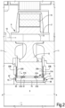
Fig.2 shows an enlargement of the bearing of one impeller of the pump ofFig.1 and relevant lubrication circuit; -
Fig.3 shows a schematic cross-sectional view of an internal bearing component according to line III-III ofFig.2 ; -
Fig. 4 shows a schematic cross-sectional view of a second embodiment of a bearing according to the present disclosure; -
Fig.5 shows a cross-sectional view according to line V-V ofFig.4 ; and -
Fig.6 shows a schematic cross-sectional view of a third embodiment of a bearing according to the present disclosure. - A novel and useful bearing structure has been developed, to improve the dynamic behavior of bearings, such as in particular, but not exclusively, PCD bearings and other bearings characterized by high stiffness. The novel bearings include two components, arranged coaxial to one another. One component rotates integrally with a rotary machine part, such as an impeller of a rotodynamic pump. The other component is stationarily housed in the machine housing. The stationary component includes damping features, which prevent or reduce the propagation of vibrations between the rotary machine component and the stationary structure of the machine.
- In embodiments disclosed herein, the stationary component of the bearing includes two co-axial substantially cylindrical members, namely an internal one and an external one. The internal and external members form a gap therebetween. In the gap a resilient damping feature is arranged, which is adapted to allow dampened displacements of the external cylindrical member with respect to the internal cylindrical member. Displacements can be in a radial direction and/or in a tangential direction. Displacements can be provoked by vibrations of a rotary machine component, mounted for integral rotation with the external bearing component. The vibrations propagate through bearing pads from the outer component to the inner component and are dampened by the resilient damping feature arranged in the gap formed in the inner component, between the external cylindrical member and the internal cylindrical member thereof. This results in efficient damping of vibrations and reduced propagation of the vibrations generated by the rotary machine component towards the stationary structure of the machine.
- The novel bearing structure will now be described in combination with a rotodynamic pump, and specifically with a multi-phase rotodynamic pump. Those skilled in the art will nevertheless appreciate that the bearing structure of the present disclosure can be used with advantage also in other applications, for instance whenever a relatively stiff bearing is used to support a rotary machine part subject to vibrations and damping of the vibrations is desired.
- Referring now to
Fig.1 , arotodynamic pump 1 comprises acasing 3 and astationary shaft 5 arranged therein. The stationary shaft can be formed by a beam extending longitudinally through the pump casing. In other embodiments, thestationary shaft 5 can be comprised of stacked shaft sections connected to one another by an axial tie rod. The pump can comprise a plurality ofstages 7. Eachpump stage 7 comprises arespective impeller 9, which is supported for rotation on theshaft 5 and coacts with astatoric part 11, i.e. with a non-rotating, stationary component of thepump 1. If thestationary shaft 5 is formed by stacked sections, eachimpeller 9 can be supported by a separate section of thestationary shaft 5. - Referring now to
Fig.2 , with continuing reference toFig.1 , eachimpeller 9 comprises a disc-shaped body 12 and a plurality ofblades 13 distributed annularly around a rotation axis A-A. Aprocess fluid path 15 extends across the bladed portion of eachimpeller 9. Mechanical power generated by embedded electric motors, to be described, rotate theimpellers 9, which transfer the power to the process fluid along theprocess fluid path 15 to boost the pressure of the fluid. - In the exemplary embodiment of
Figs. 1 and2 , eachimpeller 9 comprises ashroud 17. Eachimpeller 9 is driven into rotation by a respectiveelectric motor 18 housed in thecasing 3. Eachelectric motor 18 includes arotor 19, arranged around theshroud 17 and rotating with theimpeller 9, as well as astator 21 developing around therotor 19 and stationarily housed in thecasing 3. - Each
impeller 9 is supported on thestationary shaft 5 by means of arespective bearing 31. In the embodiment ofFigs. 1 and2 each bearing 31 comprises a stationaryinner bearing component 31B and an outerrotary bearing component 31A. The twocomponents - In presently preferred embodiments the
bearing 31 is a PCD (PolyCrystalline Diamond) bearing comprised ofradial bearing pads 51A on the rotaryouter bearing component 31A andradial bearing pads 51B on the stationaryinner component 31B. Each bearing 31 can further includeaxial bearing pads 53A on the rotaryouter bearing component 31A andaxial bearing pads 53B on the stationaryinner bearing component 31B or on thestatoric part 11 of thepump 1. - According to embodiments disclosed herein, the
inner bearing component 31B is configured to provide a vibration damping effect, such that vibrations generated by the rotatingimpeller 9, for instance, are dampened and not propagated, or propagated only in a dampened manner, through therespective bearing 31 towards thestationary structure 11 of thepump 1. - Referring now to
Fig.3 , with continuing reference toFig.2 , the innerstationary bearing component 31B comprises an externalcylindrical member 61 and an internalcylindrical member 63. The internal and externalcylindrical members stationary shaft 5, on which the internalcylindrical member 63 can be mounted. The bearingpads 51B are integral with the externalcylindrical member 61. - The external
cylindrical member 61 and the internalcylindrical member 63 can be coupled to one another by aferrule 65, seeFig.2 , which can be screwed on one end of the internalcylindrical member 63. The opposite end of the internalcylindrical member 63 can form aflange 67. The externalcylindrical member 61 can be pressed by screwing theferrule 65, between theflange 67 and theferrule 65. O-ring orsimilar seals cylindrical member 63 and the externalcylindrical member 61. - A
cylindrical gap 75 is formed between the externalcylindrical member 61 and the internalcylindrical member 63. Thecylindrical gap 75 extends in an axial direction, i.e. parallel to the rotation axis A-A. In the cylindrical gap 75 a resilient damping feature is arranged. As used herein, the term "resilient damping feature" can be understood as any mechanical device or combination of devices arranged between the externalcylindrical member 61 and the internalcylindrical member 63 and co-acting therewith, such that the vibration of one said internal and externalcylindrical members cylindrical members - A lubricant fluid, preferably a lubricant liquid, such as oil or other preferably high-viscosity fluid can fill the
gap 75. - In some embodiments, as shown in
Fig.3 , the resilient damping feature includes acorrugated tubular sheet 77. Thecorrugated tubular sheet 77 comprisescorrugations 77A extending axially, i.e. parallel to the rotation axis A-A of thebearing 31. Due to thecorrugated tubular sheet 77 arranged in thegap 75, the externalcylindrical member 61 and the internalcylindrical member 63 can move one with respect to the other to a limited extent in a radial direction, for instance due to oscillations induced by vibrations of therotary impeller 9. The radial displacement of the externalcylindrical member 61 with respect to the internalcylindrical member 63 is obtained through the compliance of thecorrugations 77A under a radial load applied thereto. The oscillation in radial direction is dampened by the resilient damping feature, provided by thecorrugated tubular sheet 77. - In addition to a radial displacement, the external
cylindrical member 61 can also move tangentially with respect to the internalcylindrical member 63, i.e. the twomembers Fig.3 ) can be limited by tangential displacement limiting devices. For instance said devices can include at least one, and preferably a set of firstradial projections 81 extending radially inwardly from an inner surface of the externalcylindrical member 61 towards the outer surface of the internalcylindrical member 63. The tangential displacement limiting devices can further include at least one, and preferably a set of secondradial projections 83 extending radially outwardly from the outer surface of the internalcylindrical member 63 towards the externalcylindrical member 61. The firstradial projections 81 and the secondradial projections 83 extend betweenadjacent corrugations 77A, such that the tangential displacement of the internal and externalcylindrical members radial projections corrugations 77A. - A tangential displacement provoked by vibrations or oscillations induced by the rotary impeller causes flexural deformation of the
corrugations 77A of thecorrugated tubular sheet 77, which therefore dampens the oscillations. - The damping effect of the resilient damping feature can be improved by high-viscosity lubrication liquid contained in the
gap 75 and/or by friction between the resilient dampingfeature 77 and the surfaces of the external and internalcylindrical members corrugations 77A of the resilient dampingfeature 77. - Referring now to
Figs. 4 and5 , with continuing reference toFig.2 , in other, currently less preferred embodiments, the resilient damping feature can include a set of compressible inserts arranged in the gap between the externalcylindrical member 61 and the internalcylindrical member 63. InFigs. 4 and5 the same or equivalent parts or elements already shown inFigs 2 and3 and described above are labeled with the same reference numbers and are not described again. In the embodiment ofFigs. 4 and5 the resilient damping feature includes a set of O-rings 78 housed in thegap 75. Annular grooves on the innercylindrical surface 61A of the externalcylindrical member 61 and annular grooves in the outercylindrical surface 63A of the internalcylindrical member 63 can be provided, to retain the O-rings 78 in the correct position. - Referring to
Fig. 6 , with continuing reference toFig.2 , in yet further, currently less preferred embodiments, the resilient damping feature can include a set of longitudinally extendingresilient members 79. InFig.6 the same or equivalent parts or elements already shown inFigs 2 and3 and described above are labeled with the same reference numbers and are not described again. Theresilient members 79 are housed in thegap 75 and can be retained in position by longitudinal grooves provided in the innercylindrical surface 61A of the externalcylindrical member 61 and longitudinal grooves in the outercylindrical surface 63A of the internalcylindrical member 63. - While the invention has been described in terms of various specific embodiments, it will be apparent to those of ordinary skill in the art that many modifications, changes, and omissions are possible without departing from the scope of the claims.
Claims (13)
- A bearing (31) comprising an inner bearing component (31B) and an outer bearing component (31A), said outer bearing component (31A) and said inner bearing component (31B) being arranged coaxially to one another and adapted to rotate one with respect to the other around an axis of the bearing (31);the inner bearing component (31B) comprising: an external cylindrical member (61) having an outer bearing surface and an inner cavity; an internal cylindrical member (63), arranged in the inner cavity of the external cylindrical member (61) and substantially coaxial thereto; wherein the external cylindrical member (61) and the internal cylindrical member (63) form a gap (75) therebetween; and wherein a resilient damping feature (77; 78; 79) is arranged in the gap (75);characterized by further comprising bearing pads (51B) on the outer bearing surface of the external cylindrical member (61) and wherein the outer bearing component (31A) has an inner cylindrical bearing surface provided with a plurality of bearing pads (51A) arranged to co-act with the bearing pads (51B) on the outer bearing surface of the inner bearing component (31B).
- The bearing of claim 1, wherein the resilient damping feature (77; 78; 79) is adapted to allow at least one of dampened radial displacements and dampened tangential displacements of the external cylindrical member (61) with respect to the internal cylindrical member (63).
- The bearing of claim 1 or claim 2, wherein the bearing pads (51A, 51B) are polycrystalline diamond pads.
- The bearing of any one of the preceding claims, wherein the resilient damping feature includes a corrugated tubular sheet (77) arranged in the gap (75) between the external cylindrical member (61) and the internal cylindrical member (63).
- The bearing of claim 4, wherein the corrugated tubular sheet (77) is made of metal.
- The bearing of claim 4 or 5, wherein the corrugated tubular sheet (77) comprises corrugations extending parallel to an axis of the external cylindrical member (61) and of the internal cylindrical member (63).
- The bearing of claim 6, further comprising displacement limiting devices (81, 83), adapted to limit the displacement of the external cylindrical member (61) and of the internal cylindrical member (63), one with respect to the other.
- The bearing of claim 6 or 7, wherein: the inner cavity of the external cylindrical member (61) has first radial projections (81) extending inwardly from a surface of the inner cavity towards the corrugated tubular sheet (77); the internal cylindrical member (63) has second radial projections (83) extending outwardly towards the external cylindrical member (61); the first radial projections (81) and the second radial projections (83) co-acting with the corrugations of the corrugated tubular sheet (77) to limit angular displacements of the external cylindrical member (61) with respect to the internal cylindrical member (63).
- The bearing of any one of claims 1 to 3, wherein the resilient damping feature includes one of: a set of annular resilient damping members (78) arranged around an axis of the external cylindrical member (61) and internal cylindrical member (63), distanced from one another along said axis; a set of linear resilient damping members (79) extending in a direction parallel to the axis of the external cylindrical member (61) and internal cylindrical member (63) and distanced from one another around said axis.
- The bearing of any one of the preceding claims, wherein the gap (75) is filled with a liquid, preferably with a lubricant liquid.
- The bearing of any one of the preceding claims, further including axial bearing pads (53A) on the rotary outer bearing component (31A) and axial bearing pads (53B) on the stationary inner bearing component (31B).
- A rotary machine comprising a stationary shaft (5) and a rotor (19) supported for rotation on the stationary shaft (5); wherein the rotor (19) is supported on the stationary shaft (5) by at least one bearing according to any one of the preceding claims.
- A rotodynamic pump comprising a casing (3), a stationary shaft (5) arranged in the casing (3) and at least one rotary impeller (9) arranged for rotation on the stationary shaft (5) by at least one bearing according to any one of the claims 1 to 11.
Applications Claiming Priority (2)
| Application Number | Priority Date | Filing Date | Title |
|---|---|---|---|
| IT102019000000635A IT201900000635A1 (en) | 2019-01-15 | 2019-01-15 | A COMPONENT OF DAMPED CUSHION, CUSHION INCLUDING SAID COMPONENT, AND ROTATING MACHINE INCLUDING SAID CUSHION |
| PCT/EP2020/025012 WO2020148090A1 (en) | 2019-01-15 | 2020-01-14 | A dampened bearing component, bearing including said component, and rotary machine including said bearing |
Publications (2)
| Publication Number | Publication Date |
|---|---|
| EP3911864A1 EP3911864A1 (en) | 2021-11-24 |
| EP3911864B1 true EP3911864B1 (en) | 2023-05-03 |
Family
ID=66049600
Family Applications (1)
| Application Number | Title | Priority Date | Filing Date |
|---|---|---|---|
| EP20700863.2A Active EP3911864B1 (en) | 2019-01-15 | 2020-01-14 | A dampened bearing component, bearing including said component, and rotary machine including said bearing |
Country Status (7)
| Country | Link |
|---|---|
| US (1) | US11859662B2 (en) |
| EP (1) | EP3911864B1 (en) |
| JP (1) | JP7482138B2 (en) |
| KR (1) | KR102604512B1 (en) |
| CN (1) | CN113260798B (en) |
| IT (1) | IT201900000635A1 (en) |
| WO (1) | WO2020148090A1 (en) |
Family Cites Families (32)
| Publication number | Priority date | Publication date | Assignee | Title |
|---|---|---|---|---|
| US1370599A (en) * | 1920-03-02 | 1921-03-08 | Nordiska Kullager Ab | Resilient support for machinery |
| US3122399A (en) * | 1962-04-11 | 1964-02-25 | David U Hunter | Self-balancing bearing construction |
| US3318642A (en) * | 1963-10-17 | 1967-05-09 | Bunting Brass & Bronze Co | Self-aligning bearing |
| US4286827A (en) * | 1979-10-11 | 1981-09-01 | Barry Wright Corporation | Cylindrical elastomeric bearing |
| JPS62148795U (en) * | 1986-03-12 | 1987-09-19 | ||
| US5209577A (en) * | 1991-11-13 | 1993-05-11 | Camco International, Inc. | Downhole rotating machine having compliant radial bearings |
| JP3354270B2 (en) * | 1994-01-26 | 2002-12-09 | オイレス工業株式会社 | Bearing device for steering column |
| JPH07217658A (en) * | 1994-02-01 | 1995-08-15 | Hitachi Ltd | Ceramic bearing |
| DE19701178C2 (en) * | 1997-01-15 | 2000-12-07 | Umfotec Umformtechnik Gmbh | Bearing ring |
| FR2882408B1 (en) * | 2005-02-21 | 2008-09-05 | Ct Stephanois De Recherchees | GUIDE ORGAN |
| JP2007247711A (en) * | 2006-03-14 | 2007-09-27 | Nsk Ltd | Rolling bearings for underwater rotating equipment |
| DE102007019766B3 (en) * | 2007-04-25 | 2008-11-20 | Siemens Ag | Bearing device with a magnetically rotatably mounted relative to a stator about an axis shaft and a damping device |
| DE102007031606B4 (en) * | 2007-07-06 | 2020-10-29 | Dr. Ing. H.C. F. Porsche Aktiengesellschaft | Hydraulically damping bearing |
| JP5276414B2 (en) * | 2008-11-07 | 2013-08-28 | ゼネラル・エレクトリック・カンパニイ | Followable hybrid gas journal bearings using an integral wire mesh damper |
| DE102009024093B4 (en) * | 2009-06-06 | 2011-07-07 | Aktiebolaget Skf | Bearing arrangement for a carrying roller |
| DE102009031063A1 (en) * | 2009-06-30 | 2011-01-05 | Schaeffler Technologies Gmbh & Co. Kg | roller bearing assembly |
| CN102166809B (en) * | 2010-02-25 | 2015-12-09 | Skf公司 | For the manufacture of method and the bearing arrangement of bearing arrangement |
| EP2643601B1 (en) * | 2010-11-23 | 2019-08-07 | Lufkin Industries, LLC | Bridge spring centering device for squeeze film dampers |
| CN203430998U (en) * | 2013-08-23 | 2014-02-12 | 桐乡辰宇机械有限公司 | Shockproof bearing seat for transmission shaft |
| EP2899414A1 (en) * | 2014-01-23 | 2015-07-29 | Siemens Aktiengesellschaft | Damped bearing of a rotor shaft |
| EP3102833B1 (en) | 2014-02-03 | 2021-03-31 | Nuovo Pignone S.r.l. | Multistage turbomachine with embedded electric motors |
| DE102014003324B4 (en) * | 2014-03-08 | 2015-11-26 | Audi Ag | Rubber-metal sleeve bearing |
| RU2677754C2 (en) | 2014-05-21 | 2019-01-21 | Конинклейке Филипс Н.В. | Hydrodynamic bearing, x-ray tube, x-ray system and method of manufacturing hydrodynamic bearing |
| US9562562B2 (en) * | 2014-05-30 | 2017-02-07 | Us Synthetic Corporation | Bearing assemblies and apparatuses including superhard bearing elements |
| CN204533201U (en) * | 2015-04-08 | 2015-08-05 | 武汉理工大学 | Tail bearing after damp type |
| US9789887B2 (en) * | 2015-05-11 | 2017-10-17 | Aktiebolaget Skf | Backing ring assembly for railcar axle bearings |
| US9746029B1 (en) * | 2016-04-18 | 2017-08-29 | General Electric Company | Bearing |
| US20180087516A1 (en) * | 2016-09-27 | 2018-03-29 | General Electric Company | Turbomachine with active magnetic bearings |
| JP6823902B2 (en) | 2017-04-03 | 2021-02-03 | オイレス工業株式会社 | Plain bearing |
| CN107461405A (en) * | 2017-07-12 | 2017-12-12 | 武汉理工大学 | A kind of mesh fluid texture type damping bearing |
| US20190186245A1 (en) * | 2017-12-20 | 2019-06-20 | Baker Hughes, A Ge Company, Llc | Lubricant Circulating Pump For Electrical Submersible Pump Motor |
| US11286985B2 (en) * | 2018-07-30 | 2022-03-29 | Xr Downhole Llc | Polycrystalline diamond bearings for rotating machinery with compliance |
-
2019
- 2019-01-15 IT IT102019000000635A patent/IT201900000635A1/en unknown
-
2020
- 2020-01-14 CN CN202080008178.4A patent/CN113260798B/en active Active
- 2020-01-14 EP EP20700863.2A patent/EP3911864B1/en active Active
- 2020-01-14 US US17/309,989 patent/US11859662B2/en active Active
- 2020-01-14 JP JP2021540595A patent/JP7482138B2/en active Active
- 2020-01-14 WO PCT/EP2020/025012 patent/WO2020148090A1/en not_active Ceased
- 2020-01-14 KR KR1020217025271A patent/KR102604512B1/en active Active
Also Published As
| Publication number | Publication date |
|---|---|
| IT201900000635A1 (en) | 2020-07-15 |
| JP2022518693A (en) | 2022-03-16 |
| WO2020148090A1 (en) | 2020-07-23 |
| KR102604512B1 (en) | 2023-11-20 |
| BR112021013994A2 (en) | 2021-09-21 |
| US20220074422A1 (en) | 2022-03-10 |
| US11859662B2 (en) | 2024-01-02 |
| CN113260798B (en) | 2023-07-04 |
| KR20210124995A (en) | 2021-10-15 |
| EP3911864A1 (en) | 2021-11-24 |
| CN113260798A (en) | 2021-08-13 |
| JP7482138B2 (en) | 2024-05-13 |
Similar Documents
| Publication | Publication Date | Title |
|---|---|---|
| US6469411B2 (en) | Compliant foil fluid film bearing with eddy current damper | |
| EP2252804B1 (en) | Bearing system for rotor in rotating machines | |
| US5895202A (en) | Molecular drag pump | |
| JP2005248822A (en) | Generator-integrated water turbine and motor-integrated pump | |
| JPH08512377A (en) | Friction vacuum pump with bearing support | |
| US11821433B2 (en) | Rotary machine with improved shaft | |
| CN107532505B (en) | rotating machinery | |
| US6241392B1 (en) | Hybrid bearing | |
| US11859662B2 (en) | Dampened bearing component, bearing including said component, and rotary machine including said bearing | |
| JP6767720B2 (en) | Turbomachinery | |
| CN113708564A (en) | Fluid power generator | |
| KR100723040B1 (en) | Bearing assembly for high speed rotor | |
| WO2001006149A1 (en) | Assembly of one-way clutch and bearing | |
| JP2017145935A (en) | Bearing device, rotating machine | |
| RU49588U1 (en) | SUBMERSIBLE HIGH SPEED PUMP UNIT | |
| BR112021013994B1 (en) | BEARING, ROTARY MACHINE AND ROTODYNAMIC PUMP | |
| JPH09144691A (en) | Turbo compressor | |
| JP2015143550A (en) | Bearing device and rotary machine | |
| KR19980034760A (en) | Hydrostatic Fluid Bearings | |
| JP2007278370A (en) | Dynamic pressure bearing and dynamic pressure bearing motor using the same |
Legal Events
| Date | Code | Title | Description |
|---|---|---|---|
| STAA | Information on the status of an ep patent application or granted ep patent |
Free format text: STATUS: UNKNOWN |
|
| STAA | Information on the status of an ep patent application or granted ep patent |
Free format text: STATUS: THE INTERNATIONAL PUBLICATION HAS BEEN MADE |
|
| PUAI | Public reference made under article 153(3) epc to a published international application that has entered the european phase |
Free format text: ORIGINAL CODE: 0009012 |
|
| STAA | Information on the status of an ep patent application or granted ep patent |
Free format text: STATUS: REQUEST FOR EXAMINATION WAS MADE |
|
| 17P | Request for examination filed |
Effective date: 20210805 |
|
| AK | Designated contracting states |
Kind code of ref document: A1 Designated state(s): AL AT BE BG CH CY CZ DE DK EE ES FI FR GB GR HR HU IE IS IT LI LT LU LV MC MK MT NL NO PL PT RO RS SE SI SK SM TR |
|
| DAV | Request for validation of the european patent (deleted) | ||
| DAX | Request for extension of the european patent (deleted) | ||
| STAA | Information on the status of an ep patent application or granted ep patent |
Free format text: STATUS: EXAMINATION IS IN PROGRESS |
|
| RAP3 | Party data changed (applicant data changed or rights of an application transferred) |
Owner name: NUOVO PIGNONE TECNOLOGIE S.R.L. |
|
| 17Q | First examination report despatched |
Effective date: 20220523 |
|
| GRAP | Despatch of communication of intention to grant a patent |
Free format text: ORIGINAL CODE: EPIDOSNIGR1 |
|
| STAA | Information on the status of an ep patent application or granted ep patent |
Free format text: STATUS: GRANT OF PATENT IS INTENDED |
|
| INTG | Intention to grant announced |
Effective date: 20230202 |
|
| GRAS | Grant fee paid |
Free format text: ORIGINAL CODE: EPIDOSNIGR3 |
|
| GRAA | (expected) grant |
Free format text: ORIGINAL CODE: 0009210 |
|
| STAA | Information on the status of an ep patent application or granted ep patent |
Free format text: STATUS: THE PATENT HAS BEEN GRANTED |
|
| REG | Reference to a national code |
Ref country code: DE Ref legal event code: R081 Ref document number: 602020010400 Country of ref document: DE Owner name: NUOVO PIGNONE TECNOLOGIE S.R.L., IT Free format text: FORMER OWNER: NUOVO PIGNONE TECNOLOGIE - S.R.L., FLORENCE, IT |
|
| AK | Designated contracting states |
Kind code of ref document: B1 Designated state(s): AL AT BE BG CH CY CZ DE DK EE ES FI FR GB GR HR HU IE IS IT LI LT LU LV MC MK MT NL NO PL PT RO RS SE SI SK SM TR |
|
| REG | Reference to a national code |
Ref country code: GB Ref legal event code: FG4D |
|
| REG | Reference to a national code |
Ref country code: DE Ref legal event code: R096 Ref document number: 602020010400 Country of ref document: DE |
|
| REG | Reference to a national code |
Ref country code: AT Ref legal event code: REF Ref document number: 1564832 Country of ref document: AT Kind code of ref document: T Effective date: 20230515 Ref country code: CH Ref legal event code: EP |
|
| REG | Reference to a national code |
Ref country code: IE Ref legal event code: FG4D |
|
| REG | Reference to a national code |
Ref country code: NL Ref legal event code: FP Ref country code: SE Ref legal event code: TRGR |
|
| REG | Reference to a national code |
Ref country code: NO Ref legal event code: T2 Effective date: 20230503 |
|
| P01 | Opt-out of the competence of the unified patent court (upc) registered |
Effective date: 20230526 |
|
| REG | Reference to a national code |
Ref country code: LT Ref legal event code: MG9D |
|
| REG | Reference to a national code |
Ref country code: AT Ref legal event code: MK05 Ref document number: 1564832 Country of ref document: AT Kind code of ref document: T Effective date: 20230503 |
|
| PG25 | Lapsed in a contracting state [announced via postgrant information from national office to epo] |
Ref country code: PT Free format text: LAPSE BECAUSE OF FAILURE TO SUBMIT A TRANSLATION OF THE DESCRIPTION OR TO PAY THE FEE WITHIN THE PRESCRIBED TIME-LIMIT Effective date: 20230904 Ref country code: ES Free format text: LAPSE BECAUSE OF FAILURE TO SUBMIT A TRANSLATION OF THE DESCRIPTION OR TO PAY THE FEE WITHIN THE PRESCRIBED TIME-LIMIT Effective date: 20230503 Ref country code: AT Free format text: LAPSE BECAUSE OF FAILURE TO SUBMIT A TRANSLATION OF THE DESCRIPTION OR TO PAY THE FEE WITHIN THE PRESCRIBED TIME-LIMIT Effective date: 20230503 |
|
| PG25 | Lapsed in a contracting state [announced via postgrant information from national office to epo] |
Ref country code: RS Free format text: LAPSE BECAUSE OF FAILURE TO SUBMIT A TRANSLATION OF THE DESCRIPTION OR TO PAY THE FEE WITHIN THE PRESCRIBED TIME-LIMIT Effective date: 20230503 Ref country code: PL Free format text: LAPSE BECAUSE OF FAILURE TO SUBMIT A TRANSLATION OF THE DESCRIPTION OR TO PAY THE FEE WITHIN THE PRESCRIBED TIME-LIMIT Effective date: 20230503 Ref country code: LV Free format text: LAPSE BECAUSE OF FAILURE TO SUBMIT A TRANSLATION OF THE DESCRIPTION OR TO PAY THE FEE WITHIN THE PRESCRIBED TIME-LIMIT Effective date: 20230503 Ref country code: LT Free format text: LAPSE BECAUSE OF FAILURE TO SUBMIT A TRANSLATION OF THE DESCRIPTION OR TO PAY THE FEE WITHIN THE PRESCRIBED TIME-LIMIT Effective date: 20230503 Ref country code: IS Free format text: LAPSE BECAUSE OF FAILURE TO SUBMIT A TRANSLATION OF THE DESCRIPTION OR TO PAY THE FEE WITHIN THE PRESCRIBED TIME-LIMIT Effective date: 20230903 Ref country code: HR Free format text: LAPSE BECAUSE OF FAILURE TO SUBMIT A TRANSLATION OF THE DESCRIPTION OR TO PAY THE FEE WITHIN THE PRESCRIBED TIME-LIMIT Effective date: 20230503 Ref country code: GR Free format text: LAPSE BECAUSE OF FAILURE TO SUBMIT A TRANSLATION OF THE DESCRIPTION OR TO PAY THE FEE WITHIN THE PRESCRIBED TIME-LIMIT Effective date: 20230804 |
|
| PG25 | Lapsed in a contracting state [announced via postgrant information from national office to epo] |
Ref country code: FI Free format text: LAPSE BECAUSE OF FAILURE TO SUBMIT A TRANSLATION OF THE DESCRIPTION OR TO PAY THE FEE WITHIN THE PRESCRIBED TIME-LIMIT Effective date: 20230503 |
|
| PG25 | Lapsed in a contracting state [announced via postgrant information from national office to epo] |
Ref country code: SK Free format text: LAPSE BECAUSE OF FAILURE TO SUBMIT A TRANSLATION OF THE DESCRIPTION OR TO PAY THE FEE WITHIN THE PRESCRIBED TIME-LIMIT Effective date: 20230503 |
|
| PG25 | Lapsed in a contracting state [announced via postgrant information from national office to epo] |
Ref country code: SM Free format text: LAPSE BECAUSE OF FAILURE TO SUBMIT A TRANSLATION OF THE DESCRIPTION OR TO PAY THE FEE WITHIN THE PRESCRIBED TIME-LIMIT Effective date: 20230503 Ref country code: SK Free format text: LAPSE BECAUSE OF FAILURE TO SUBMIT A TRANSLATION OF THE DESCRIPTION OR TO PAY THE FEE WITHIN THE PRESCRIBED TIME-LIMIT Effective date: 20230503 Ref country code: RO Free format text: LAPSE BECAUSE OF FAILURE TO SUBMIT A TRANSLATION OF THE DESCRIPTION OR TO PAY THE FEE WITHIN THE PRESCRIBED TIME-LIMIT Effective date: 20230503 Ref country code: EE Free format text: LAPSE BECAUSE OF FAILURE TO SUBMIT A TRANSLATION OF THE DESCRIPTION OR TO PAY THE FEE WITHIN THE PRESCRIBED TIME-LIMIT Effective date: 20230503 Ref country code: DK Free format text: LAPSE BECAUSE OF FAILURE TO SUBMIT A TRANSLATION OF THE DESCRIPTION OR TO PAY THE FEE WITHIN THE PRESCRIBED TIME-LIMIT Effective date: 20230503 Ref country code: CZ Free format text: LAPSE BECAUSE OF FAILURE TO SUBMIT A TRANSLATION OF THE DESCRIPTION OR TO PAY THE FEE WITHIN THE PRESCRIBED TIME-LIMIT Effective date: 20230503 |
|
| REG | Reference to a national code |
Ref country code: DE Ref legal event code: R097 Ref document number: 602020010400 Country of ref document: DE |
|
| PLBE | No opposition filed within time limit |
Free format text: ORIGINAL CODE: 0009261 |
|
| STAA | Information on the status of an ep patent application or granted ep patent |
Free format text: STATUS: NO OPPOSITION FILED WITHIN TIME LIMIT |
|
| 26N | No opposition filed |
Effective date: 20240206 |
|
| PG25 | Lapsed in a contracting state [announced via postgrant information from national office to epo] |
Ref country code: SI Free format text: LAPSE BECAUSE OF FAILURE TO SUBMIT A TRANSLATION OF THE DESCRIPTION OR TO PAY THE FEE WITHIN THE PRESCRIBED TIME-LIMIT Effective date: 20230503 |
|
| PG25 | Lapsed in a contracting state [announced via postgrant information from national office to epo] |
Ref country code: SI Free format text: LAPSE BECAUSE OF FAILURE TO SUBMIT A TRANSLATION OF THE DESCRIPTION OR TO PAY THE FEE WITHIN THE PRESCRIBED TIME-LIMIT Effective date: 20230503 Ref country code: IT Free format text: LAPSE BECAUSE OF FAILURE TO SUBMIT A TRANSLATION OF THE DESCRIPTION OR TO PAY THE FEE WITHIN THE PRESCRIBED TIME-LIMIT Effective date: 20230503 |
|
| PG25 | Lapsed in a contracting state [announced via postgrant information from national office to epo] |
Ref country code: MC Free format text: LAPSE BECAUSE OF FAILURE TO SUBMIT A TRANSLATION OF THE DESCRIPTION OR TO PAY THE FEE WITHIN THE PRESCRIBED TIME-LIMIT Effective date: 20230503 |
|
| PG25 | Lapsed in a contracting state [announced via postgrant information from national office to epo] |
Ref country code: MC Free format text: LAPSE BECAUSE OF FAILURE TO SUBMIT A TRANSLATION OF THE DESCRIPTION OR TO PAY THE FEE WITHIN THE PRESCRIBED TIME-LIMIT Effective date: 20230503 |
|
| PG25 | Lapsed in a contracting state [announced via postgrant information from national office to epo] |
Ref country code: LU Free format text: LAPSE BECAUSE OF NON-PAYMENT OF DUE FEES Effective date: 20240114 |
|
| PG25 | Lapsed in a contracting state [announced via postgrant information from national office to epo] |
Ref country code: LU Free format text: LAPSE BECAUSE OF NON-PAYMENT OF DUE FEES Effective date: 20240114 |
|
| PG25 | Lapsed in a contracting state [announced via postgrant information from national office to epo] |
Ref country code: BE Free format text: LAPSE BECAUSE OF NON-PAYMENT OF DUE FEES Effective date: 20240131 |
|
| PG25 | Lapsed in a contracting state [announced via postgrant information from national office to epo] |
Ref country code: BE Free format text: LAPSE BECAUSE OF NON-PAYMENT OF DUE FEES Effective date: 20240131 |
|
| REG | Reference to a national code |
Ref country code: BE Ref legal event code: MM Effective date: 20240131 |
|
| PG25 | Lapsed in a contracting state [announced via postgrant information from national office to epo] |
Ref country code: BG Free format text: LAPSE BECAUSE OF FAILURE TO SUBMIT A TRANSLATION OF THE DESCRIPTION OR TO PAY THE FEE WITHIN THE PRESCRIBED TIME-LIMIT Effective date: 20230503 |
|
| PG25 | Lapsed in a contracting state [announced via postgrant information from national office to epo] |
Ref country code: BG Free format text: LAPSE BECAUSE OF FAILURE TO SUBMIT A TRANSLATION OF THE DESCRIPTION OR TO PAY THE FEE WITHIN THE PRESCRIBED TIME-LIMIT Effective date: 20230503 |
|
| PG25 | Lapsed in a contracting state [announced via postgrant information from national office to epo] |
Ref country code: IE Free format text: LAPSE BECAUSE OF NON-PAYMENT OF DUE FEES Effective date: 20240114 |
|
| PG25 | Lapsed in a contracting state [announced via postgrant information from national office to epo] |
Ref country code: IE Free format text: LAPSE BECAUSE OF NON-PAYMENT OF DUE FEES Effective date: 20240114 |
|
| PG25 | Lapsed in a contracting state [announced via postgrant information from national office to epo] |
Ref country code: CY Free format text: LAPSE BECAUSE OF FAILURE TO SUBMIT A TRANSLATION OF THE DESCRIPTION OR TO PAY THE FEE WITHIN THE PRESCRIBED TIME-LIMIT; INVALID AB INITIO Effective date: 20200114 |
|
| PG25 | Lapsed in a contracting state [announced via postgrant information from national office to epo] |
Ref country code: HU Free format text: LAPSE BECAUSE OF FAILURE TO SUBMIT A TRANSLATION OF THE DESCRIPTION OR TO PAY THE FEE WITHIN THE PRESCRIBED TIME-LIMIT; INVALID AB INITIO Effective date: 20200114 |
|
| PG25 | Lapsed in a contracting state [announced via postgrant information from national office to epo] |
Ref country code: TR Free format text: LAPSE BECAUSE OF FAILURE TO SUBMIT A TRANSLATION OF THE DESCRIPTION OR TO PAY THE FEE WITHIN THE PRESCRIBED TIME-LIMIT Effective date: 20230503 |
|
| PGFP | Annual fee paid to national office [announced via postgrant information from national office to epo] |
Ref country code: GB Payment date: 20251217 Year of fee payment: 7 |
|
| PGFP | Annual fee paid to national office [announced via postgrant information from national office to epo] |
Ref country code: NO Payment date: 20251218 Year of fee payment: 7 |
|
| PGFP | Annual fee paid to national office [announced via postgrant information from national office to epo] |
Ref country code: NL Payment date: 20251217 Year of fee payment: 7 Ref country code: FR Payment date: 20251218 Year of fee payment: 7 |
|
| PGFP | Annual fee paid to national office [announced via postgrant information from national office to epo] |
Ref country code: SE Payment date: 20251217 Year of fee payment: 7 |
|
| REG | Reference to a national code |
Ref country code: CH Ref legal event code: U11 Free format text: ST27 STATUS EVENT CODE: U-0-0-U10-U11 (AS PROVIDED BY THE NATIONAL OFFICE) Effective date: 20260201 |
|
| PGFP | Annual fee paid to national office [announced via postgrant information from national office to epo] |
Ref country code: DE Payment date: 20251217 Year of fee payment: 7 |
|
| PGFP | Annual fee paid to national office [announced via postgrant information from national office to epo] |
Ref country code: CH Payment date: 20260201 Year of fee payment: 7 |