EP3911534B1 - Device for mounting a seat or a standing plate relative to a frame of a vehicle - Google Patents
Device for mounting a seat or a standing plate relative to a frame of a vehicle Download PDFInfo
- Publication number
- EP3911534B1 EP3911534B1 EP20701248.5A EP20701248A EP3911534B1 EP 3911534 B1 EP3911534 B1 EP 3911534B1 EP 20701248 A EP20701248 A EP 20701248A EP 3911534 B1 EP3911534 B1 EP 3911534B1
- Authority
- EP
- European Patent Office
- Prior art keywords
- seat
- standing plate
- holder
- frame
- vehicle
- Prior art date
- Legal status (The legal status is an assumption and is not a legal conclusion. Google has not performed a legal analysis and makes no representation as to the accuracy of the status listed.)
- Active
Links
Images







Classifications
-
- B—PERFORMING OPERATIONS; TRANSPORTING
- B60—VEHICLES IN GENERAL
- B60N—SEATS SPECIALLY ADAPTED FOR VEHICLES; VEHICLE PASSENGER ACCOMMODATION NOT OTHERWISE PROVIDED FOR
- B60N2/00—Seats specially adapted for vehicles; Arrangement or mounting of seats in vehicles
- B60N2/02—Seats specially adapted for vehicles; Arrangement or mounting of seats in vehicles the seat or part thereof being movable, e.g. adjustable
- B60N2/04—Seats specially adapted for vehicles; Arrangement or mounting of seats in vehicles the seat or part thereof being movable, e.g. adjustable the whole seat being movable
- B60N2/14—Seats specially adapted for vehicles; Arrangement or mounting of seats in vehicles the seat or part thereof being movable, e.g. adjustable the whole seat being movable rotatable, e.g. to permit easy access
-
- B—PERFORMING OPERATIONS; TRANSPORTING
- B60—VEHICLES IN GENERAL
- B60N—SEATS SPECIALLY ADAPTED FOR VEHICLES; VEHICLE PASSENGER ACCOMMODATION NOT OTHERWISE PROVIDED FOR
- B60N2/00—Seats specially adapted for vehicles; Arrangement or mounting of seats in vehicles
- B60N2/005—Arrangement or mounting of seats in vehicles, e.g. dismountable auxiliary seats
-
- B—PERFORMING OPERATIONS; TRANSPORTING
- B62—LAND VEHICLES FOR TRAVELLING OTHERWISE THAN ON RAILS
- B62D—MOTOR VEHICLES; TRAILERS
- B62D51/00—Motor vehicles characterised by the driver not being seated
- B62D51/02—Motor vehicles characterised by the driver not being seated the driver standing in the vehicle
-
- B—PERFORMING OPERATIONS; TRANSPORTING
- B66—HOISTING; LIFTING; HAULING
- B66F—HOISTING, LIFTING, HAULING OR PUSHING, NOT OTHERWISE PROVIDED FOR, e.g. DEVICES WHICH APPLY A LIFTING OR PUSHING FORCE DIRECTLY TO THE SURFACE OF A LOAD
- B66F9/00—Devices for lifting or lowering bulky or heavy goods for loading or unloading purposes
- B66F9/06—Devices for lifting or lowering bulky or heavy goods for loading or unloading purposes movable, with their loads, on wheels or the like, e.g. fork-lift trucks
- B66F9/075—Constructional features or details
- B66F9/0759—Details of operating station, e.g. seats, levers, operator platforms, cabin suspension
-
- B—PERFORMING OPERATIONS; TRANSPORTING
- B60—VEHICLES IN GENERAL
- B60N—SEATS SPECIALLY ADAPTED FOR VEHICLES; VEHICLE PASSENGER ACCOMMODATION NOT OTHERWISE PROVIDED FOR
- B60N2/00—Seats specially adapted for vehicles; Arrangement or mounting of seats in vehicles
- B60N2/02—Seats specially adapted for vehicles; Arrangement or mounting of seats in vehicles the seat or part thereof being movable, e.g. adjustable
- B60N2002/0204—Seats specially adapted for vehicles; Arrangement or mounting of seats in vehicles the seat or part thereof being movable, e.g. adjustable characterised by the seat or seat part turning about or moving along a non-standard, particular axis, i.e. an axis different from the axis characterising the conventional movement
- B60N2002/0212—Seats specially adapted for vehicles; Arrangement or mounting of seats in vehicles the seat or part thereof being movable, e.g. adjustable characterised by the seat or seat part turning about or moving along a non-standard, particular axis, i.e. an axis different from the axis characterising the conventional movement the seat or seat part turning about or moving along a longitudinal axis
-
- B—PERFORMING OPERATIONS; TRANSPORTING
- B60—VEHICLES IN GENERAL
- B60N—SEATS SPECIALLY ADAPTED FOR VEHICLES; VEHICLE PASSENGER ACCOMMODATION NOT OTHERWISE PROVIDED FOR
- B60N2/00—Seats specially adapted for vehicles; Arrangement or mounting of seats in vehicles
- B60N2/02—Seats specially adapted for vehicles; Arrangement or mounting of seats in vehicles the seat or part thereof being movable, e.g. adjustable
- B60N2002/0204—Seats specially adapted for vehicles; Arrangement or mounting of seats in vehicles the seat or part thereof being movable, e.g. adjustable characterised by the seat or seat part turning about or moving along a non-standard, particular axis, i.e. an axis different from the axis characterising the conventional movement
- B60N2002/0216—Seats specially adapted for vehicles; Arrangement or mounting of seats in vehicles the seat or part thereof being movable, e.g. adjustable characterised by the seat or seat part turning about or moving along a non-standard, particular axis, i.e. an axis different from the axis characterising the conventional movement the seat or seat part turning about or moving along a transversal axis
-
- B—PERFORMING OPERATIONS; TRANSPORTING
- B60—VEHICLES IN GENERAL
- B60N—SEATS SPECIALLY ADAPTED FOR VEHICLES; VEHICLE PASSENGER ACCOMMODATION NOT OTHERWISE PROVIDED FOR
- B60N2/00—Seats specially adapted for vehicles; Arrangement or mounting of seats in vehicles
- B60N2/24—Seats specially adapted for vehicles; Arrangement or mounting of seats in vehicles for particular purposes or particular vehicles
- B60N2002/247—Seats specially adapted for vehicles; Arrangement or mounting of seats in vehicles for particular purposes or particular vehicles to support passengers in a half-standing position
-
- B—PERFORMING OPERATIONS; TRANSPORTING
- B60—VEHICLES IN GENERAL
- B60N—SEATS SPECIALLY ADAPTED FOR VEHICLES; VEHICLE PASSENGER ACCOMMODATION NOT OTHERWISE PROVIDED FOR
- B60N2205/00—General mechanical or structural details
- B60N2205/20—Measures for elimination or compensation of play or backlash
Definitions
- the present invention relates to a device for mounting a seat relative to a frame of a vehicle.
- the invention also relates to a device which is intended for use by the driver standing on a plate mounted to the frame of the vehicle.
- it relates to such devices with which a driver of the vehicle is exposed to significantly less impact forces and vibrations, e.g. relating to the vehicle driving along an uneven surface, than what is the case for a known vehicle of the same type.
- vehicles are steered by a person seated on a seat that is mounted firmly to the frame of the vehicle in a manner which means that impact forces, change of direction, and vibrations caused by the vehicle driving along an uneven surface or bumping into obstacles are transferred from the frame to the seat and thus also to the driver.
- Similar effects are experienced in relation to vehicles driven by a person standing on a plate mounted to the frame of the vehicle.
- Such influences experienced during driving may not just be uncomfortable but may also, over short or long term, be damaging to the driver's body either due to one single high load or due to repeated exposure to smaller loads over a longer period.
- a sudden impact may give the driver a fright and thereby influence the driving safety negatively.
- an improved device for mounting a seat or a standing plate relative to a frame of a vehicle would be advantageous.
- WO2018/138776 A1 discloses a target support device that includes a bottom configured to be fixed to a floor of a vehicle and have a concave curved surface and three or more support members disposed on an upper side of the bottom and configured to come into contact with a convex curved surface formed on a lower surface of a target to support the target and have a surface which is formed as a curved surface.
- US2018/022238 A1 discloses a vehicle seat in which a thickness of a seatback is reduced.
- a supporting mechanism comprises a pivot shaft, a hub member, and a reinforcement shaft. The pivot shaft and the reinforcement shaft are overlapped with a width direction of the vehicle at least partially.
- EP3524468 A1 discloses a soil cultivating machine with a chassis and a machine frame carried by the chassis.
- the soil cultivating machine has a seat bearing arrangement in the area of the operator's stand, which is designed to be brought into detachable bearing engagement with a counter bearing arrangement of an operator's seat.
- a device for mounting a seat relative to a frame of a vehicle comprising a seat holder, and the seat holder having an outer surface, wherein:
- frame is meant a body part of the vehicle to which other components of the vehicle are also fastened. In particular, the frame will move, such as vibrate, when the vehicle is driven across an uneven surface.
- the frame could also be referred to as the chassis of the vehicle.
- the shape of the cross-section of the seat holder may be circular, but the shape may also be e.g. elliptic or square.
- the seat holder can be mounted to the frame at a lower end, and this will be the case in the embodiments shown in the figures. However, the mounting could also be somewhere along the length of the seat holder.
- the seat holder or the standing plate is able to move freely relative to the frame within adjustable limits.
- freely and “free” movement is meant that the only forces acting against such movement are the small frictional forces of the pivotal mounting. Small vibrations occurring during driving along an uneven surface typically have force components in more directions and planes.
- An advantage of the free movement obtained with the present invention is that possible transfer of these small vibrations from the frame to the driver during driving are minimized compared to known systems.
- the pivotal mounting is preferably obtained via a bearing, such as a roller bearing, to ensure that the movement is as free from resistance as possible.
- a bearing such as a roller bearing
- the effect of such an arrangement is that when the vehicle is driven along an uneven ground surface, such as a floor or a field, or bumping into obstacles in the surroundings, such as a kerb or wall, the frame follows these variations without the related movements being transferred to the seat or to the standing plate.
- This means that a driver of the vehicle will not be exposed to the vibrations and impact forces that would occur in case of the vehicle comprising a traditional fixedly mounted seat or standing plate.
- the driver will remain in a stable and substantially non-moving state despite the uneven surface so that the driver will experience the driving as if it was along a smooth surface.
- this relative movement is lateral, i.e. sideways, with respect to a driving direction of the vehicle.
- the possible vibrations are the most critical for the driver because the structure of the back of a human body is designed to meet impact especially in the forward-backward orientation.
- the body With impact and movement in this direction, the body has many joint structures onto which the impact can be distributed so that the forces are not critical; an example is the combined load carrying capability of the hips, pelvis and back. Therefore, movement in this direction can take place in a smooth and flexible way. This is not the case in the lateral direction.
- Vibration dampers for use in the present invention may e.g. be dumpers made from a resilient material. Such dumpers are known from other applications, such as for damping the propagation of vibrations from a machine or a fridge to the surroundings.
- the vibration dampers may alternatively or in combinations therewith be springs, such as helical springs, or vibration dampers made from other kinds of materials suitable for providing the damping effect. Vibration dampers on their own and the general use thereof are known to the person skilled in the art.
- a given damper provides both the damping of the relative movement and a stop establishing a physical limit for the movement.
- the stop is established by the damper not being further compressible by the actual acting forces.
- a damper and a stop may be provided as separate components so that a movement is first dampened by the vibration damper and then completely limited if the flange reaches the stop.
- the dampers may act in compression only; this will e.g. be the case for a block of resilient material having a free surface facing towards the flange with which it is to engage.
- the dampers may also act both in compression and tension so that one damper can work in more directions. This can e.g. be obtained by use of a spring fastened in both ends thereof.
- the possibility of adjusting the position of the at least one first vibration damper and/or the at least one stop relative to the at least one flange may include one or more possible kinds of adjustment. It may e.g. be possible to change a mounting position between a plurality of possible mounting holes arranged at different distances from a central axis of the seat holder. It may also be possible to vary the possible pivotal movement by varying a distance between the flange and the respective first vibration damper or stop. This can e.g. be done by mounting the component to be adjusted with threaded rods as will be shown in the figures.
- the device may also be provided with automatic or semi-automatic adjustment possibilities so that the limits can be adjusted during driving, e.g. when driving onto a more uneven surface.
- Such adjustment systems can be based on the adjustable components being mounted and adjusted via actuators, such as pneumatic, hydraulic or electric actuators.
- the positions of all the present vibration dampers and stops are individually adjustable so that different relative movement patterns are possible; this will be explained in relation to the figures. It may e.g. be relevant for a given application to allow for a larger freedom of movement parallel to a driving direction than perpendicular thereto.
- the seat holder or the standing plate holder is pivotally mounted in two separate hinges having non-parallel axes of rotation.
- the seat holder or the standing plate holder is rotatable 360 degrees around a central axis thereof, so that the transfer of impact forces and vibrations to a driver sitting on the seat or standing on the standing plate can be eliminated in all directions.
- the seat holder or the standing plate holder may e.g. be mounted to the frame via a cardan joint so that the seat holder or the standing plate holder is rotatable 360 degrees around a central point of the cardan joint.
- a cardan joint is also referred to as a universal joint.
- the pivotal mounting of the seat holder or the standing plate holder in relation to the frame is the only mounting thereof.
- minor further support which could then be considered as part of the mounting.
- the seat holder when used for mounting a seat, the seat holder comprises a seat rod adapted to carry the seat, and a tubular shaft having a circumferential wall, the tubular shaft having the seat rod retained within the circumferential wall.
- the shape of the hollow space surrounded by the circumferential wall should match the shape of the seat rod to facilitate a secure retaining thereof while still allowing for adjustment of the seat height, if relevant.
- the at least one flange preferably extends laterally outwards from the outer surface of a circumferential wall of the tubular shaft.
- the flange and the dampers and stops are typically located at the ends of the tubular shaft.
- the scope of the invention also covers embodiments having corresponding arrangements within the circumferential wall if there is enough room. Examples of possible designs will be shown in the figures.
- an inner surface of the circumferential wall of the tubular shaft is provided with at least one set, such as row, of circumferentially arranged second vibration dampers, the second vibration dampers extending to the seat rod so that the seat rod is supported by the second vibration dampers.
- the inner surface may be provided with at least two sets of circumferentially arranged second vibration dampers which sets are spaced apart along the tubular shaft.
- a set of second vibration dampers is a plurality of such dampers arranged in a row; this is what will be shown in the figures.
- the second vibration dampers in one row may be circumferentially offset from the second vibration in another row to provide a more stable support and damping for all directions of the forces to be dampened.
- Other designs of the second vibrations dampers are also covered by the scope of the invention.
- An example is second vibration dampers made in the form of annular rings.
- the standing plate when used for mounting of a standing plate, is provided with a downwardly facing annular ring or a plurality of downwardly facing circumferentially arranged tabs, and an inner surface of the annular ring or inner surfaces of the tabs is/are provided with at least one set, such as row, of circumferentially arranged second vibration dampers, the second vibration dampers extending to the standing plate holder so that the standing plate is supported by the second vibration dampers.
- circumferentially arranged tabs is meant that the tabs are arranged around a central region of the standing plate. They may be arranged near a circumference of the standing plate, but they may also be arranged at a distance therefrom. Furthermore, they may be arranged at different distances from the circumference of the standing plate, such as at different distances from a central region of the standing plate.
- Each of the at least one first vibration damper may be made from of a resilient material and may be in the form of a tapered block with rounded tip, the rounded tip facing towards the at least one flange.
- the second vibration dampers may be made from of a resilient material and may be in the form of tapered blocks with rounded tips, the rounded tips facing towards the seat rod or towards the standing plate holder.
- Such first and second vibration dampers may e.g. made from rubber-based material. A possible adjustment of a vibration damper will be to change between a plurality of available vibration dampers having different damping characteristics, such as being made from different materials.
- the first and/or second vibration dampers may be provided with threading, such as being a threaded rod, and the position of those vibration dampers may be adjustable by screwing the threading relative to a threaded counterpart, such as a nut.
- a lower end of the seat rod is arranged on a third vibration damper adapted to dampen the movements of the seat rod when in use on a moving vehicle.
- a third vibration damper dampens the vertical movement, e.g. due to the vehicle driving over a bump. However, it also dampens the vibrations in other directions.
- the seat holder or standing plate holder and a drive unit of the vehicle may be mounted on a slewing ring which is arranged and mounted so that it can rotate with respect to the frame.
- a rotational movement may e.g. be obtained by having a plurality of bearings or balls or a low-friction material arranged between the base plate and an annular slewing ring, which slewing ring is typically circumferentially arranged around a lower end of the drive unit.
- the rotational movement of the drive unit and the seat holder or standing plate holder relative to the frame may alternatively be obtained by arranging the drive unit and the seat holder or standing plate holder on a plate which is rotationally mounted on the frame.
- the driving direction of the vehicle can be changed to match a desired manner of driving the vehicle.
- Such a change of direction by rotating the slewing ring, and thereby the seat holder or the standing plate and the drive unit may be manual or it may be driven e.g. by a motor or hydraulic system.
- the relative rotational movement should preferably be locked during driving.
- the device may be provided with sensors, such as strain gauges, via which the forces acting on some or all of the vibration dampers during driving can be registered by use of a monitoring system.
- sensors such as strain gauges, via which the forces acting on some or all of the vibration dampers during driving can be registered by use of a monitoring system.
- sensors may be built into the dampers, or they may be arranged so close thereto that representative signals are obtained.
- details of the damping characteristics and loading patterns can be analysed and used to adjust and optimize the individual positions of the vibration dampers according to a given driving condition.
- the invention in a second aspect, relates to a vehicle, such as a three-wheeled vehicle, comprising a device as described above and, for embodiments comprising a seat holder, a seat mounted to the vehicle by use of the device.
- vehicle is typically a motor-driven vehicle, but the scope of the invention also covers other kinds of vehicles, such as e.g. a pedal driven vehicle.
- a three-wheeled vehicle is particularly useful for driving around sharp corners.
- Such a kind of vehicle is e.g. used for moving beds in a hospital.
- a vehicle may have the seat or the standing plate mounted by use of more than one device as described above.
- the invention relates to a device 1 for mounting a seat 2 relative to a frame 3 of a vehicle in a manner which protects the driver of the vehicle against impact resulting from e.g. driving along an uneven surface. Such impact can both be unpleasant and cause damage to the driver's body as explained above.
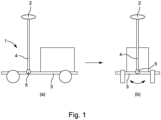
- the overall concept of a vehicle comprising such a device 1 is shown schematically in figure 1 .
- the driver is not shown in the figures, but he will be sitting on the seat 2 while driving the vehicle.
- the device 1 has a seat holder 4 which carries the seat 2 on which the driver may be fully sitting so that his whole weight is carried by the seat and thereby by the seat holder 4. He may also be half standing so that only a part of his weight is carried by the seat holder 4.
- the seat holder 4 is shown as being vertically arranged. However, it may also be arranged at an inclined angle, if desired. Such an inclined seat holder may e.g. provide the same effect as having the seat arranged offset from a longitudinal axis of a vertical seat holder.
- FIG 1 other parts of the vehicle that are not relevant for the description of the invention are marked as a box.
- the seat holder 4 is pivotally mounted to the frame 3 so that the frame 3 and the seat holder 4 can move relative to each other laterally in at least one plane, when the device 1 is in use mounted on the vehicle.
- the pivotal mounting 5 is schematically shown as a circle.
- Figure 1.a is a side view with the arrow indicating a possible driving direction of the vehicle; the driving direction may also be the opposite of the illustrated one.
- Figure 1.b is a rear view with the curved arrow indicating the possible lateral mutual movement of the frame 3 and the seat holder 4 e.g. in response to driving on an inclined surface or due to the forces and vibrations experienced during driving. As explained in more details above, vibrations and impact in the lateral direction, i.e.
- FIG. 2 shows different embodiments of the invention when used for mounting a seat.
- the illustrated embodiments are not intended to show an exhaustive list of possible designs.
- the pivotal mounting 5 of the seat holder 4 in relation to the frame 3 is the only mounting thereof.
- the seat holder 4 has an outer surface 6 and is provided with at least one flange 7 extending laterally from the outer surface 6 of the seat holder 4. Different numbers of flanges 7 will be shown in the following figures in order to illustrate some possible designs which are covered by the scope of the invention.
- Figure 2 shows different embodiments in which the device 1 is provided with first vibration dampers 8 that are arranged to limit the possible movement of the at least one flange 7 thereby providing free movement until limits for the pivotal movement of the frame 3 relative to the seat holder 4 are met.
- the first vibration dampers 8 therefore include stops, since when the resilient material from which they are made cannot be further compressed by the actual forces, the movement is also stopped.
- the driving direction is preferably perpendicular or substantially perpendicular to the plane of the paper.
- the seat holder 4 is shown schematically as a hollow shaft.
- the seat may be arranged on a seat rod to be retained within this shaft, or the seat may be fastened directly to an upper end of the hollow shaft; this will be shown below.
- the pivotal joint 5 is arranged below the central axis of the seat holder 4 whereas in figure 2.c it is offset therefrom.
- Figure 2.a shows an embodiment with two flanges 7 extending in opposite directions and each having a first vibration damper 8 fastened thereto. This means that the frame 3 can move relatively to the seat holder 4 until the frame 3 is first dampened and then stopped by one of the first vibration dampers 8.
- Figure 2.b shows a similar design in which two first vibration dampers 8 are arranged at one of the flanges 7 and one first vibration damper 8 is arranged at the other flange 7.
- the two first vibration dampers 8 are shown to allow for the same movement of the flanges 7, but that does not need to be the case.
- three first vibration dampers 8 are shown just to illustrate different possible locations thereof.
- Figure 2.c shows an embodiment having one horizontally extending flange 7, wherein the movement of the flange 7 relative to the seat holder 4 is limited by first vibration dampers 8 arranged on different parts of the frame 3.
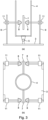
- Figure 3 shows an embodiment having two vertical flanges 7 extending from the outer surface 6 of the seat holder 4.
- Figure 3.a is a side view so that only one of the flanges 7 is visible, and figure 3.b is a top view showing both flanges 7.
- the first vibration dampers 8 are arranged on the frame 3 in the form of vertically extending frame parts 9 fixedly connected to a lower part of the frame 3.
- the device 1 may also be provided with stops 10 in addition to first vibration dampers 8.
- Figure 4 shows schematically an example of a device 1 provided with both first vibration dampers 8 and stops 10.
- the design resembles the one in figure 2.a .
- the designs shown in figure 2.b, 2.c , and 3 could also be provided with one or more stops.
- Such stops 10 establish the maximum limits for the possible movement and may thus be considered as safety measures used to ensure that these limits are not exceeded independent of the function, such as compressibility, of the first vibration dampers 8. Such limits may e.g. related to what would make the vehicle fall over, and they will typically be determined as part of a design process.
- the positions of the stops 10 are not adjustable. However, it would also be possible the provide the stops 10 with means for adjusting the position in the same manner as what has been shown for the first vibration dampers 8.
- the positions of the first vibration dampers 8 and/or the stops relative to the at least one flange 7 are adjustable.
- the limits for the possible movement of the at least one flange 7 and thereby the possible movement of the frame 3 relative to the seat holder 4 are adjustable. This will typically be obtained by providing them with a threading which can interact with threaded counterparts, such as nuts 11, as shown in figure 3 .
- Figure 5 shows schematically two other embodiment in which the seat holder 4 is pivotally mounted in two separate hinges 5 having non-parallel axes of rotation so that the seat holder 4 is rotatable 360 degrees. This means that the driver is protected against vibrations and impact in all directions and not just sideways with respect to the driving direction.
- Figures 5.a and 5.b show one embodiment from two perpendicular directions
- figures 5.c and 5.d show another embodiment from two perpendicular orientations.
- the two axes are arranged perpendicular to each other. One of these axes is arranged parallel to the driving direction so that it will allow for the lateral relative movement. In the illustrated embodiments, this axis is arranged in the same plane as the central axis of the seat holder 4.
- a device may also comprise additional parts 19 on which the various components are mounted.
- FIG. 6 shows schematically and in top view how various movement patterns can be obtained in relation to a given central point, such as a central axis of the seat holder 4.
- the central point is shown schematically as a dot in figure 6 .
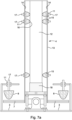
- Figure 7 shows schematically an embodiment of the invention in which the seat holder 4 comprises a seat rod 12, which carries the seat, and a tubular shaft 13 having a circumferential wall.
- the tubular shaft 13 has the seat rod 12 retained within the circumferential wall.
- the shape of the hollow space surrounded by the circumferential wall should match the shape of the seat rod 12 to facilitate a secure retaining thereof while still allowing for adjustment of the seat height, if relevant.
- an inner surface 14 of the circumferential wall of the tubular shaft 13 is provided with three rows of circumferentially arranged second vibration dampers 15 which are spaced apart along the tubular shaft 13 as shown in figure 7.a .
- the second vibration dampers 15 extend to the seat rod 12 so that the seat rod 12 is supported by the second vibration dampers 15.
- Figure 7.b is a cross-sectional view of a section through a row of second vibration dampers 15 in figure 7.a .
- vibration dampers which is shown in figure 7 can be used both for the first vibration dampers 8 and for the second vibration dampers 15.
- a vibration damper is made from of a resilient material and is in the form of a tapered block with rounded tip 16.
- the vibration damper 8,15 is to be arranged so that the rounded tip face 16 towards the component with which it is to engage, i.e. the at least one flange 7 or the seat rod 12, respectively.
- the vibration dampers 8,15 in figure 7 are each provided with a threaded rod 17 so that the position of the vibration damper 8,15 is adjustable by screwing the threading relative to a threaded counterpart, such as a nut 11.
- the lower end of the seat rod 12 is arranged on a third vibration damper 18 adapted to dampen the transfer of movements and vibrations from the frame 3 to the seat rod 12 when in use on a moving vehicle.
- the third vibration damper 18 is in the form of a resilient material having straight edges.
- studies made in relation to the present invention has shown that the use of a third vibration damper 18 having a shape as shown schematically in figure 8 provides a more efficient total damping of the vibrations and movements when used in combination with second vibration dampers as explained in relation to figure 7 .
- Such a shape as shown in figure 8 of the third vibration damper 18 gives it a lateral flexibility in all lateral directions which provides enough freedom to the second vibration dampers 15 to deform to such an extent that they apply the optimal dampening by deforming in different directions.
- a number of parameters can be varied. They include the size, number, damping characteristics and positions of the vibration dampers; the size, number, and positions of possible stops; the arrangement of the one or more flanges; and the number of devices used for a seat or for a standing plate.
- a device will typically be designed so that several of these parameters can be fine-tuned e.g. to match a given driver. Both the initial design and the fine-tuning can be based e.g. on a combination of experiments and computer simulations.
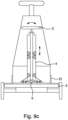
- Figure 9 shows schematically an embodiment of the invention in which the seat holder 4 and the drive unit 19 of the vehicle are mounted on a slewing ring 21.
- a corresponding arrangement could be used for the mounting of a standing plate.
- Figure 9.a is a side view
- figure 9.b is a top view
- figure 9.c is a rear or front view, dependent on the driving direction of the vehicle.
- the illustrated vehicle further comprises a battery 20 for supplying power to the drive unit 19.
- the slewing ring 21 is arranged and mounted so that it can rotate with respect to the frame 3, which frame in the illustrated embodiment is a base plate of the vehicle. This rotational movement can e.g. be obtained by having a plurality of bearings or balls or a low-friction material arranged between the base plate and an annular slewing ring, which slewing ring is circumferentially arranged around a lower end of the drive unit 19.
- the rotational movement of the drive unit 19 and the seat holder 4 relative to the frame 3 is obtained by arranging the drive unit 19 and the seat holder 4 on a plate which is rotationally mounted on the frame 3.
- the driving direction of the vehicle can be changed to match a desired manner of driving the vehicle.
- Such a change of direction by rotating the slewing ring 21, and thereby the seat holder 4 and the drive unit 19, may be manual or it may be driven e.g. by a motor or hydraulic system.
- the relative rotational movement should preferably be locked during driving.
- Such a rotational adjustability can be used in combination with any of the embodiments of the invention as described above and below.
- FIG 10 shows schematically an embodiment of the invention which is designed for carrying a driver standing on a standing plate 25 instead of sitting on a seat as is intended with the embodiments described in the above figures.
- This embodiment of figure 10 comprises a standing plate holder 4a which resembles the seat holder 4 in the above embodiments with respect to its functioning.
- the standing plate holder 4a comprises a laterally extending flange 7.
- the standing plate holder 4a is in the form of an annular ring
- the flange 7 is in the form of a plate extending across the inner space surrounded by the annular ring.
- the embodiment in figure 10 further comprises an intermediate plate 22 which is mounted to the frame 3 via connection rods 23 fastened e.g.
- the intermediate plate 22 would typically be circular and there would typically be a plurality of vertically extending connection rods 23 symmetrically arranged at a distance from a centre of the intermediate plate 22.
- connection rods 23 symmetrically arranged at a distance from a centre of the intermediate plate 22.
- connection rods 23 extend through matching holes 24 in the flange 7.
- the standing plate holder 4a is arranged with respect to the frame 3 by resting on at least two tapered blocks with rounded tips which in the illustrated embodiments are identical to the vibration dampers shown in the above embodiments. Other shapes fulfilling the desired function are also covered by the scope of protection. However, since they are the only physical contact between the frame and the flange 7 of the standing plate holder 4a, two of such tapered blocks form what corresponds to a pivotal mounting around which there is free movement.
- each pair of tapered blocks can be considered as such a pivotal mounting, and the remaining ones form first dampers 8 for the free movement around the respective pivotal axis.
- the tapered blocks may all be arranged at the same distance from a central vertical axis, or they may be arranged at different distances.
- Figures 11.a and 11.b show schematically top views of two examples of possible pivotal axes each formed by a pair of two tapered blocks. Each point represents a location of a tapered block, and each line represents a pivotal axis established by the respective pair of tapered blocks.
- the flange is provided with upwardly facing first dampers 8 engagable with the intermediate plate 22 in order to dampen the vibrations of the vehicle during driving.
- the standing plate 25 is provided with a downwardly facing annular ring 26 provided with second vibration dampers 15 along an inner surface.
- These second vibration dampers 15 are engagable with the standing plate holder 4a along an outer circumference thereof.
- the second dampers 15 could have been mounted on the outer circumference of the standing plate holder 4a and pointing towards an inner surface of the annular ring 26 of the standing plate 25.
- the relationship between the annular ring 26 connected to the standing plate 25 and the standing plate holder 4a and the functioning thereof resembles what has been described above in relation to figure 7a illustrating a seat holder in the form of a seat rod 12 arranged inside a tubular shaft 13.
- Figure 12 shows schematically another embodiment comprising a standing plate 25.
- This embodiment differs from the one in figure 10 by comprising a pivotal joint 5 between the flange 7 and the frame 3.
- the illustrated pivotal joint 5 comprises a block of dampening material 28.
- all of the tapered blocks with rounded tips which formed the pivotal joint in figure 10 here are first dampers 8, since the pivotal joint is now a separate element. The rest of this embodiment and the functioning thereof resembles what has been described for figure 10 .
- the standing plate 25 is shown as being provided with an annular ring 26 carrying the second vibration dampers 15.
- an annular ring 26 carrying the second vibration dampers 15.
- an alternative to such an annular ring would be to use a plurality of downwardly facing circumferentially arranged tabs 26a.
- the first and second vibration dampers 8,15 are illustrated as extending through matching holes in the elements with which they are engageable.
- Matching holes is meant that the holes are adapted to engage with the respective vibration dampers in a predetermined manner.
- Such holes for engagement could in the same way be incorporated in the embodiments shown in the previous figures.
- the damping characteristic may be optimized by varying one or more of the following design parameters for the holes: the three-dimensional shape, the size, the position, and the number.
- three-dimensional shape is meant that the plate or ring in which the hole is made has a thickness and that the shape and dimension of a hole may vary through the thickness of the plate.
- the shape does not need to be rotationally symmetrical.
- a hole may e.g. be elliptical to provide for different damping characteristics in two perpendicular directions.
- the position is meant in any direction, such as vertically or radially.
- the damping characteristic will also depend on the material of the vibration dampers as well as of the plate or ring in which the hole is made.
- the damping characteristic will also depend on the positions of the vibrations dampers, these positions being adjustable as described above. By possible variations of all these parameters, it is possible to optimize the device for a given use and to change the settings when the device is to be used for another application.
- Figure 13 shows schematically a partial view of a region around a bearingly mounted connection rod 23 of an embodiment resembling any of those in figures 10 and 12 . It is mounted by use of spherical bearing 27 which allows for the pivotal movement.
- the spherical bearing 27 may be able to slide along the connection rod 23, or it may be fixed to a predetermined position.
Landscapes
- Engineering & Computer Science (AREA)
- Transportation (AREA)
- Mechanical Engineering (AREA)
- Aviation & Aerospace Engineering (AREA)
- Structural Engineering (AREA)
- Chemical & Material Sciences (AREA)
- Combustion & Propulsion (AREA)
- Civil Engineering (AREA)
- Life Sciences & Earth Sciences (AREA)
- Geology (AREA)
- Seats For Vehicles (AREA)
Description
- The present invention relates to a device for mounting a seat relative to a frame of a vehicle. The invention also relates to a device which is intended for use by the driver standing on a plate mounted to the frame of the vehicle. In particular, it relates to such devices with which a driver of the vehicle is exposed to significantly less impact forces and vibrations, e.g. relating to the vehicle driving along an uneven surface, than what is the case for a known vehicle of the same type.
- Within many different technical fields, vehicles are steered by a person seated on a seat that is mounted firmly to the frame of the vehicle in a manner which means that impact forces, change of direction, and vibrations caused by the vehicle driving along an uneven surface or bumping into obstacles are transferred from the frame to the seat and thus also to the driver. Similar effects are experienced in relation to vehicles driven by a person standing on a plate mounted to the frame of the vehicle. Such influences experienced during driving may not just be uncomfortable but may also, over short or long term, be damaging to the driver's body either due to one single high load or due to repeated exposure to smaller loads over a longer period. Furthermore, a sudden impact may give the driver a fright and thereby influence the driving safety negatively. For some kinds of vehicles, such as cars, this is partly counteracted by building various kinds of protection, including vibration dampers and padding, into the vehicle. However, even with such known types of protection, it cannot be avoided that repetitive vibrations and hard impact are transferred to the driver of a vehicle.
- For some kinds of vehicles, it is not possible to avoid the abovementioned negative effects of the driving due to the construction of the vehicle or in order to keep the cost of the vehicle at a reasonably low level. There may e.g. be limits on the acceptable physical size or weight of the vehicle. Even for vehicles which are provided with some vibration dampers, e.g. in the form of helical springs, it is well known that they can normally only provide some extent of damping. Furthermore, such damping is typically only designed to counteract the most expected kinds of loading, such as smaller bumps, but not sudden unintended impacts, such as if the vehicle is driven over a kerb or into an obstacle, such as a wall or an overlooked object. These limits on the design are also related to the fact that many industrial vehicles are optimised with respect to the transportation function to be fulfilled and not so much with focus on protecting the driver.
- Hence, an improved device for mounting a seat or a standing plate relative to a frame of a vehicle would be advantageous.
-
WO2018/138776 A1 discloses a target support device that includes a bottom configured to be fixed to a floor of a vehicle and have a concave curved surface and three or more support members disposed on an upper side of the bottom and configured to come into contact with a convex curved surface formed on a lower surface of a target to support the target and have a surface which is formed as a curved surface.US2018/022238 A1 discloses a vehicle seat in which a thickness of a seatback is reduced. A supporting mechanism comprises a pivot shaft, a hub member, and a reinforcement shaft. The pivot shaft and the reinforcement shaft are overlapped with a width direction of the vehicle at least partially.EP3524468 A1 discloses a soil cultivating machine with a chassis and a machine frame carried by the chassis. The soil cultivating machine has a seat bearing arrangement in the area of the operator's stand, which is designed to be brought into detachable bearing engagement with a counter bearing arrangement of an operator's seat. - It is an object of the present invention to provide a device for mounting a seat or a standing plate relative to a frame of a vehicle which device is more efficient in providing damping of the transfer of forces and vibrations from the frame to the seat or to the standing plate and thereby to the driver than what is known from prior art vehicles of the same type.
- It is another object of the present invention to provide a device for mounting a seat or a standing plate relative to a frame of a vehicle which device has a higher safety against single impact loading, such as from the vehicle hitting an obstacle, being transferred to the driver of the vehicle.
- It is a further object of the present invention to provide an alternative to the prior art.
- In particular, it may be seen as an object of the present invention to provide a device for mounting a seat or a standing plate relative to a frame of a vehicle which device solves the above mentioned problems of the prior art.
- The above described object and several other objects are intended to be obtained in a first aspect of the invention by providing a device for mounting a seat relative to a frame of a vehicle, the device comprising a seat holder, and the seat holder having an outer surface,
wherein: - the seat holder is provided with at least one flange extending laterally from the seat holder,
- the seat holder is pivotally mounted to the frame so that the frame and the seat holder can move relative to each other laterally in at least one plane, when the device is in use mounted on the vehicle,
- at least one first vibration damper and/or at least one stop being arranged to limit the possible movement of the at least one flange thereby providing free movement until limits for the pivotal movement of the frame relative to the seat holder are met, and
- the positions of the at least one first vibration damper and/or the at least one stop relative to the at least one flange are adjustable so that the limits for the possible movement of the at least one flange and thereby the possible movement of the frame relative to the seat holder are adjustable.
- By "frame" is meant a body part of the vehicle to which other components of the vehicle are also fastened. In particular, the frame will move, such as vibrate, when the vehicle is driven across an uneven surface. The frame could also be referred to as the chassis of the vehicle.
- The shape of the cross-section of the seat holder may be circular, but the shape may also be e.g. elliptic or square.
- The seat holder can be mounted to the frame at a lower end, and this will be the case in the embodiments shown in the figures. However, the mounting could also be somewhere along the length of the seat holder.
- The scope of protection also covers embodiments wherein the device is intended for use by the driver standing on a plate mounted to the frame of the vehicle. Examples of such embodiments will be shown in some of the figures. Such a plate has an upper surface which would form a seat for a person choosing to sit down thereon, and the working principle and the obtained dampening would correspond to that of a seat as described in the other examples.
- Thus, as an alternative to the above-mentioned embodiments, a first aspect of the invention may alternatively be obtained by providing a device for mounting a standing plate relative to a frame of a vehicle, the device comprising the standing plate and a standing plate holder adapted to carry the standing plate, and the standing plate holder having an engagement surface,
wherein: - the standing plate holder is provided with at least one flange extending laterally from the standing plate holder,
- the standing plate holder is pivotally mounted to the frame so that the frame and the standing plate holder can move relative to each other laterally in at least one plane, when the device is in use mounted on the vehicle,
- at least one first vibration damper and/or at least one stop being arranged to limit the possible movement of the at least one flange thereby providing free movement until limits for the pivotal movement of the frame relative to the standing plate holder are met, and
- the positions of the at least one first vibration damper and/or the at least one stop relative to the at least one flange are adjustable so that the limits for the possible movement of the at least one flange and thereby the possible movement of the frame relative to the standing plate holder are adjustable.
- As mentioned above, the seat holder or the standing plate is able to move freely relative to the frame within adjustable limits. By "freely" and "free" movement is meant that the only forces acting against such movement are the small frictional forces of the pivotal mounting. Small vibrations occurring during driving along an uneven surface typically have force components in more directions and planes. An advantage of the free movement obtained with the present invention is that possible transfer of these small vibrations from the frame to the driver during driving are minimized compared to known systems.
- The pivotal mounting is preferably obtained via a bearing, such as a roller bearing, to ensure that the movement is as free from resistance as possible. The effect of such an arrangement is that when the vehicle is driven along an uneven ground surface, such as a floor or a field, or bumping into obstacles in the surroundings, such as a kerb or wall, the frame follows these variations without the related movements being transferred to the seat or to the standing plate. This means that a driver of the vehicle will not be exposed to the vibrations and impact forces that would occur in case of the vehicle comprising a traditional fixedly mounted seat or standing plate. Hereby the driver will remain in a stable and substantially non-moving state despite the uneven surface so that the driver will experience the driving as if it was along a smooth surface.
- In embodiments of the invention in which the relative movement between the frame and the seat holder or standing plate are in one plane only, this relative movement is lateral, i.e. sideways, with respect to a driving direction of the vehicle. The reason is that in this direction the possible vibrations are the most critical for the driver because the structure of the back of a human body is designed to meet impact especially in the forward-backward orientation. With impact and movement in this direction, the body has many joint structures onto which the impact can be distributed so that the forces are not critical; an example is the combined load carrying capability of the hips, pelvis and back. Therefore, movement in this direction can take place in a smooth and flexible way. This is not the case in the lateral direction. Furthermore, the vertebra is designed for lateral stability and movement forwards and backwards as that is the most typical way of moving the body. Therefore, lateral impact when driving on an uneven surface with a traditional vehicle, is transferred upwards through the driver's back that is not laterally flexible, and this results in disadvantageous influences to the body. With the present invention, such undesired impact can be avoided resulting in less risk of damage to the body of the driver as well as a more pleasant driving experience.
- Vibration dampers for use in the present invention may e.g. be dumpers made from a resilient material. Such dumpers are known from other applications, such as for damping the propagation of vibrations from a machine or a fridge to the surroundings. The vibration dampers may alternatively or in combinations therewith be springs, such as helical springs, or vibration dampers made from other kinds of materials suitable for providing the damping effect. Vibration dampers on their own and the general use thereof are known to the person skilled in the art.
- In some embodiments of the invention, a given damper provides both the damping of the relative movement and a stop establishing a physical limit for the movement. In this case, the stop is established by the damper not being further compressible by the actual acting forces. In other embodiments, a damper and a stop may be provided as separate components so that a movement is first dampened by the vibration damper and then completely limited if the flange reaches the stop. The dampers may act in compression only; this will e.g. be the case for a block of resilient material having a free surface facing towards the flange with which it is to engage. The dampers may also act both in compression and tension so that one damper can work in more directions. This can e.g. be obtained by use of a spring fastened in both ends thereof.
- The possibility of adjusting the position of the at least one first vibration damper and/or the at least one stop relative to the at least one flange may include one or more possible kinds of adjustment. It may e.g. be possible to change a mounting position between a plurality of possible mounting holes arranged at different distances from a central axis of the seat holder. It may also be possible to vary the possible pivotal movement by varying a distance between the flange and the respective first vibration damper or stop. This can e.g. be done by mounting the component to be adjusted with threaded rods as will be shown in the figures. The device may also be provided with automatic or semi-automatic adjustment possibilities so that the limits can be adjusted during driving, e.g. when driving onto a more uneven surface. Such adjustment systems can be based on the adjustable components being mounted and adjusted via actuators, such as pneumatic, hydraulic or electric actuators.
- In presently preferred embodiments of the invention, the positions of all the present vibration dampers and stops are individually adjustable so that different relative movement patterns are possible; this will be explained in relation to the figures. It may e.g. be relevant for a given application to allow for a larger freedom of movement parallel to a driving direction than perpendicular thereto.
- In some embodiments of the invention, the seat holder or the standing plate holder is pivotally mounted in two separate hinges having non-parallel axes of rotation. Hereby it is obtained that the seat holder or the standing plate holder is rotatable 360 degrees around a central axis thereof, so that the transfer of impact forces and vibrations to a driver sitting on the seat or standing on the standing plate can be eliminated in all directions. An example is embodiments wherein the seat holder or the standing plate holder may e.g. be mounted to the frame via a cardan joint so that the seat holder or the standing plate holder is rotatable 360 degrees around a central point of the cardan joint. A cardan joint is also referred to as a universal joint. In embodiments having the two axes offset relative to the longitudinal axis of the seat holder or standing plate holder, a more compact device is obtained than what is possible with a cardan joint having the same possible movements.
- In presently preferred embodiments of the invention, the pivotal mounting of the seat holder or the standing plate holder in relation to the frame is the only mounting thereof. However, it will also be possible to add minor further support which could then be considered as part of the mounting. By "minor" is meant that the pivotal mounting takes up a majority of the forces that would otherwise influence the driver.
- In some embodiments of the invention when used for mounting a seat, the seat holder comprises a seat rod adapted to carry the seat, and a tubular shaft having a circumferential wall, the tubular shaft having the seat rod retained within the circumferential wall.
- Typically, the shape of the hollow space surrounded by the circumferential wall should match the shape of the seat rod to facilitate a secure retaining thereof while still allowing for adjustment of the seat height, if relevant.
- In such embodiments with the seat holder comprising a tubular shaft retaining a seat rod adapted to carry the seat, the at least one flange preferably extends laterally outwards from the outer surface of a circumferential wall of the tubular shaft. For typical sizes of seat holders, this is where it is most convenient to arrange the flange and the dampers and stops. However, the scope of the invention also covers embodiments having corresponding arrangements within the circumferential wall if there is enough room. Examples of possible designs will be shown in the figures.
- In some embodiments of the invention with the seat holder comprising a tubular shaft retaining a seat rod adapted to carry the seat, an inner surface of the circumferential wall of the tubular shaft is provided with at least one set, such as row, of circumferentially arranged second vibration dampers, the second vibration dampers extending to the seat rod so that the seat rod is supported by the second vibration dampers.
- In such embodiments of the invention, the inner surface may be provided with at least two sets of circumferentially arranged second vibration dampers which sets are spaced apart along the tubular shaft.
- The numbers of sets and the mutual arrangements thereof may e.g. depend on the dimensions and the expected forces to be experienced during of the vehicle. In the presently preferred embodiments of the invention, a set of second vibration dampers is a plurality of such dampers arranged in a row; this is what will be shown in the figures. The second vibration dampers in one row may be circumferentially offset from the second vibration in another row to provide a more stable support and damping for all directions of the forces to be dampened. Other designs of the second vibrations dampers are also covered by the scope of the invention. An example is second vibration dampers made in the form of annular rings.
- In some embodiments of the invention when used for mounting of a standing plate, the standing plate is provided with a downwardly facing annular ring or a plurality of downwardly facing circumferentially arranged tabs, and an inner surface of the annular ring or inner surfaces of the tabs is/are provided with at least one set, such as row, of circumferentially arranged second vibration dampers, the second vibration dampers extending to the standing plate holder so that the standing plate is supported by the second vibration dampers. By "circumferentially arranged tabs" is meant that the tabs are arranged around a central region of the standing plate. They may be arranged near a circumference of the standing plate, but they may also be arranged at a distance therefrom. Furthermore, they may be arranged at different distances from the circumference of the standing plate, such as at different distances from a central region of the standing plate.
- Each of the at least one first vibration damper may be made from of a resilient material and may be in the form of a tapered block with rounded tip, the rounded tip facing towards the at least one flange. In embodiments having second vibration dampers, the second vibration dampers may be made from of a resilient material and may be in the form of tapered blocks with rounded tips, the rounded tips facing towards the seat rod or towards the standing plate holder. Such first and second vibration dampers may e.g. made from rubber-based material. A possible adjustment of a vibration damper will be to change between a plurality of available vibration dampers having different damping characteristics, such as being made from different materials.
- The effect of such second vibration dampers in the form of tapered blocks of resilient material and arranged as explained above is that they provide the dampening in all directions, including upwards and downwards and in rotation. This is particularly advantageous for embodiments of the invention in which a seat is offset from the longitudinal axis of the seat rod so that the torque due to the weight of the driver influences the force distribution caused by impact and movement during driving.
- The first and/or second vibration dampers may be provided with threading, such as being a threaded rod, and the position of those vibration dampers may be adjustable by screwing the threading relative to a threaded counterpart, such as a nut.
- In some embodiments of the invention comprising a seat rod, a lower end of the seat rod is arranged on a third vibration damper adapted to dampen the movements of the seat rod when in use on a moving vehicle. A possible design will be shown in relation to the figures. Such a third vibration damper dampens the vertical movement, e.g. due to the vehicle driving over a bump. However, it also dampens the vibrations in other directions.
- In any of the above-described embodiments, the seat holder or standing plate holder and a drive unit of the vehicle may be mounted on a slewing ring which is arranged and mounted so that it can rotate with respect to the frame. Such a rotational movement may e.g. be obtained by having a plurality of bearings or balls or a low-friction material arranged between the base plate and an annular slewing ring, which slewing ring is typically circumferentially arranged around a lower end of the drive unit. The rotational movement of the drive unit and the seat holder or standing plate holder relative to the frame may alternatively be obtained by arranging the drive unit and the seat holder or standing plate holder on a plate which is rotationally mounted on the frame.
- By having such a rotational mounting, it is obtained that the driving direction of the vehicle can be changed to match a desired manner of driving the vehicle. Such a change of direction by rotating the slewing ring, and thereby the seat holder or the standing plate and the drive unit, may be manual or it may be driven e.g. by a motor or hydraulic system. The relative rotational movement should preferably be locked during driving.
- In any of the embodiments as described above, the device may be provided with sensors, such as strain gauges, via which the forces acting on some or all of the vibration dampers during driving can be registered by use of a monitoring system. Such sensors may be built into the dampers, or they may be arranged so close thereto that representative signals are obtained. Hereby details of the damping characteristics and loading patterns can be analysed and used to adjust and optimize the individual positions of the vibration dampers according to a given driving condition.
- In a second aspect, the invention relates to a vehicle, such as a three-wheeled vehicle, comprising a device as described above and, for embodiments comprising a seat holder, a seat mounted to the vehicle by use of the device. The vehicle is typically a motor-driven vehicle, but the scope of the invention also covers other kinds of vehicles, such as e.g. a pedal driven vehicle. A three-wheeled vehicle is particularly useful for driving around sharp corners. Such a kind of vehicle is e.g. used for moving beds in a hospital. A vehicle may have the seat or the standing plate mounted by use of more than one device as described above.
- The first and second aspect of the present invention may each be combined. These and other aspects of the invention will be apparent from and elucidated with reference to the embodiments described hereinafter.
- The device for mounting a seat or a standing plate relative to a frame of a vehicle according to the invention will now be described in more detail with regard to the accompanying figures. The figures show one way of implementing the present invention and is not to be construed as being limiting to other possible embodiments falling within the scope of the attached claim set.
-
Figure 1 shows schematically the overall concept of a vehicle comprising a device according to the present invention.Figure 1.a is a side view, andfigure 1.b is a rear view. -
Figure 2 shows schematically different arrangements of the first vibration dampers in relation to the at least one flange and the seat holder. -
Figure 3 shows schematically an embodiment having two vertically arranged flanges adapted to engage with the first vibration dampers arranged on the frame. -
Figure 4 shows schematically the embodiment infigure 2.a further provided with stops. -
Figure 5 shows schematically two embodiments of the invention in which the seat holder is pivotally mounted in two separate hinges having non-parallel axes of rotation. -
Figure 6 shows schematically different possible movement patterns which can be obtained with the device infigure 5 provided that it has adjustable stops, possible formed by the first vibration dampers. -
Figure 7 shows schematically an embodiment of the invention comprising first, second, and third vibration dampers. -
Figure 8 shows schematically a possible design of a third vibration damper. -
Figure 9 shows schematically an embodiment of the invention in which the seat holder and the drive unit of the vehicle are mounted on a slewing ring. -
Figure 10 shows schematically an embodiment of the invention which is designed for carrying a driver standing on a standing plate. -
Figures 11.a and 11.b shows schematically top views of two examples of possible pivotal axes each formed by a pair of two tapered blocks. -
Figure 12 shows schematically another embodiment comprising a standing plate. -
Figure 13 shows schematically a partial view of a region around a bearingly mounted connection rod of an embodiment resembling any of those infigures 10 and12 . - In some embodiments, the invention relates to a
device 1 for mounting aseat 2 relative to aframe 3 of a vehicle in a manner which protects the driver of the vehicle against impact resulting from e.g. driving along an uneven surface. Such impact can both be unpleasant and cause damage to the driver's body as explained above. The overall concept of a vehicle comprising such adevice 1 is shown schematically infigure 1 . The driver is not shown in the figures, but he will be sitting on theseat 2 while driving the vehicle. Thedevice 1 has aseat holder 4 which carries theseat 2 on which the driver may be fully sitting so that his whole weight is carried by the seat and thereby by theseat holder 4. He may also be half standing so that only a part of his weight is carried by theseat holder 4. In all the figures, theseat holder 4 is shown as being vertically arranged. However, it may also be arranged at an inclined angle, if desired. Such an inclined seat holder may e.g. provide the same effect as having the seat arranged offset from a longitudinal axis of a vertical seat holder. Infigure 1 , other parts of the vehicle that are not relevant for the description of the invention are marked as a box. - The
seat holder 4 is pivotally mounted to theframe 3 so that theframe 3 and theseat holder 4 can move relative to each other laterally in at least one plane, when thedevice 1 is in use mounted on the vehicle. In this figure, the pivotal mounting 5 is schematically shown as a circle.Figure 1.a is a side view with the arrow indicating a possible driving direction of the vehicle; the driving direction may also be the opposite of the illustrated one.Figure 1.b is a rear view with the curved arrow indicating the possible lateral mutual movement of theframe 3 and theseat holder 4 e.g. in response to driving on an inclined surface or due to the forces and vibrations experienced during driving. As explained in more details above, vibrations and impact in the lateral direction, i.e. sideways with respect to the facing direction of the driver, are the most critical for the driver because the structure of the human body. With the present invention, such undesired impact can be avoided resulting in less risk of damage to the body of the driver as well as a more pleasant driving experience. -
Figure 2 shows different embodiments of the invention when used for mounting a seat. The illustrated embodiments are not intended to show an exhaustive list of possible designs. In the illustrated embodiments, the pivotal mounting 5 of theseat holder 4 in relation to theframe 3 is the only mounting thereof. Theseat holder 4 has anouter surface 6 and is provided with at least oneflange 7 extending laterally from theouter surface 6 of theseat holder 4. Different numbers offlanges 7 will be shown in the following figures in order to illustrate some possible designs which are covered by the scope of the invention. -
Figure 2 shows different embodiments in which thedevice 1 is provided withfirst vibration dampers 8 that are arranged to limit the possible movement of the at least oneflange 7 thereby providing free movement until limits for the pivotal movement of theframe 3 relative to theseat holder 4 are met. In these embodiments, thefirst vibration dampers 8 therefore include stops, since when the resilient material from which they are made cannot be further compressed by the actual forces, the movement is also stopped. - In
figure 2 , the driving direction is preferably perpendicular or substantially perpendicular to the plane of the paper. Some parts of the vehicle, such as the wheels and the seat are not shown in this figure. Theseat holder 4 is shown schematically as a hollow shaft. The seat may be arranged on a seat rod to be retained within this shaft, or the seat may be fastened directly to an upper end of the hollow shaft; this will be shown below. In the embodiments infigures 2.a and 2.b, thepivotal joint 5 is arranged below the central axis of theseat holder 4 whereas infigure 2.c it is offset therefrom. -
Figure 2.a shows an embodiment with twoflanges 7 extending in opposite directions and each having afirst vibration damper 8 fastened thereto. This means that theframe 3 can move relatively to theseat holder 4 until theframe 3 is first dampened and then stopped by one of thefirst vibration dampers 8.Figure 2.b shows a similar design in which twofirst vibration dampers 8 are arranged at one of theflanges 7 and onefirst vibration damper 8 is arranged at theother flange 7. In the embodiments infigure 2.a and 2.b , the twofirst vibration dampers 8 are shown to allow for the same movement of theflanges 7, but that does not need to be the case. Infigure 2.b , threefirst vibration dampers 8 are shown just to illustrate different possible locations thereof. The illustrated embodiment would also work as intended with either the lower second vibration damper or the right second vibration omitted.Figure 2.c shows an embodiment having one horizontally extendingflange 7, wherein the movement of theflange 7 relative to theseat holder 4 is limited byfirst vibration dampers 8 arranged on different parts of theframe 3. -
Figure 3 shows an embodiment having twovertical flanges 7 extending from theouter surface 6 of theseat holder 4.Figure 3.a is a side view so that only one of theflanges 7 is visible, andfigure 3.b is a top view showing bothflanges 7. In this embodiment, thefirst vibration dampers 8 are arranged on theframe 3 in the form of vertically extendingframe parts 9 fixedly connected to a lower part of theframe 3. - If desired, the
device 1 may also be provided withstops 10 in addition tofirst vibration dampers 8.Figure 4 shows schematically an example of adevice 1 provided with bothfirst vibration dampers 8 and stops 10. For ease of understanding, the design resembles the one infigure 2.a . In similar ways, the designs shown infigure 2.b, 2.c , and3 could also be provided with one or more stops. Such stops 10 establish the maximum limits for the possible movement and may thus be considered as safety measures used to ensure that these limits are not exceeded independent of the function, such as compressibility, of thefirst vibration dampers 8. Such limits may e.g. related to what would make the vehicle fall over, and they will typically be determined as part of a design process. In the embodiment shown infigure 4 , the positions of thestops 10 are not adjustable. However, it would also be possible the provide thestops 10 with means for adjusting the position in the same manner as what has been shown for thefirst vibration dampers 8. - The positions of the
first vibration dampers 8 and/or the stops relative to the at least oneflange 7 are adjustable. Hereby it is obtained that the limits for the possible movement of the at least oneflange 7 and thereby the possible movement of theframe 3 relative to theseat holder 4 are adjustable. This will typically be obtained by providing them with a threading which can interact with threaded counterparts, such asnuts 11, as shown infigure 3 . -
Figure 5 shows schematically two other embodiment in which theseat holder 4 is pivotally mounted in twoseparate hinges 5 having non-parallel axes of rotation so that theseat holder 4 is rotatable 360 degrees. This means that the driver is protected against vibrations and impact in all directions and not just sideways with respect to the driving direction.Figures 5.a and 5.b show one embodiment from two perpendicular directions, andfigures 5.c and 5.d show another embodiment from two perpendicular orientations. In the illustrated embodiments, the two axes are arranged perpendicular to each other. One of these axes is arranged parallel to the driving direction so that it will allow for the lateral relative movement. In the illustrated embodiments, this axis is arranged in the same plane as the central axis of theseat holder 4. The other one of the illustrated axes is arranged offset relative to the longitudinal axis of theseat holder 4. Hereby a more compact device is obtained than what would be possible with a cardan joint having the same possible movements. As shown infigure 5 , a device may also compriseadditional parts 19 on which the various components are mounted. - With embodiments having two separate pivotal mountings as e.g. shown in
figure 5 and also having adjustably arranged first vibration dampers and/or stops, it is possible to obtain different possible degrees of freedom with respect to the movement with the same device. This is obtained by adjusting the positions and thereby the limits they provide.Figure 6 shows schematically and in top view how various movement patterns can be obtained in relation to a given central point, such as a central axis of theseat holder 4. The central point is shown schematically as a dot infigure 6 . -
Figure 7 shows schematically an embodiment of the invention in which theseat holder 4 comprises aseat rod 12, which carries the seat, and atubular shaft 13 having a circumferential wall. Thetubular shaft 13 has theseat rod 12 retained within the circumferential wall. The shape of the hollow space surrounded by the circumferential wall should match the shape of theseat rod 12 to facilitate a secure retaining thereof while still allowing for adjustment of the seat height, if relevant. In the embodiment shown infigure 7 , aninner surface 14 of the circumferential wall of thetubular shaft 13 is provided with three rows of circumferentially arrangedsecond vibration dampers 15 which are spaced apart along thetubular shaft 13 as shown infigure 7.a . Thesecond vibration dampers 15 extend to theseat rod 12 so that theseat rod 12 is supported by thesecond vibration dampers 15.Figure 7.b is a cross-sectional view of a section through a row ofsecond vibration dampers 15 infigure 7.a . - The design of vibration dampers which is shown in
figure 7 can be used both for thefirst vibration dampers 8 and for thesecond vibration dampers 15. Such a vibration damper is made from of a resilient material and is in the form of a tapered block with roundedtip 16. Thevibration damper tip face 16 towards the component with which it is to engage, i.e. the at least oneflange 7 or theseat rod 12, respectively. As also explained above, thevibration dampers figure 7 are each provided with a threadedrod 17 so that the position of thevibration damper nut 11. - In
figure 7 , the lower end of theseat rod 12 is arranged on athird vibration damper 18 adapted to dampen the transfer of movements and vibrations from theframe 3 to theseat rod 12 when in use on a moving vehicle. In this embodiment, thethird vibration damper 18 is in the form of a resilient material having straight edges. However, studies made in relation to the present invention has shown that the use of athird vibration damper 18 having a shape as shown schematically infigure 8 provides a more efficient total damping of the vibrations and movements when used in combination with second vibration dampers as explained in relation tofigure 7 . Such a shape as shown infigure 8 of thethird vibration damper 18 gives it a lateral flexibility in all lateral directions which provides enough freedom to thesecond vibration dampers 15 to deform to such an extent that they apply the optimal dampening by deforming in different directions. - When a device according to the invention is designed to match a given application, a number of parameters can be varied. They include the size, number, damping characteristics and positions of the vibration dampers; the size, number, and positions of possible stops; the arrangement of the one or more flanges; and the number of devices used for a seat or for a standing plate. A device will typically be designed so that several of these parameters can be fine-tuned e.g. to match a given driver. Both the initial design and the fine-tuning can be based e.g. on a combination of experiments and computer simulations.
-
Figure 9 shows schematically an embodiment of the invention in which theseat holder 4 and thedrive unit 19 of the vehicle are mounted on aslewing ring 21. A corresponding arrangement could be used for the mounting of a standing plate.Figure 9.a is a side view,figure 9.b is a top view, andfigure 9.c is a rear or front view, dependent on the driving direction of the vehicle. The illustrated vehicle further comprises abattery 20 for supplying power to thedrive unit 19. The slewingring 21 is arranged and mounted so that it can rotate with respect to theframe 3, which frame in the illustrated embodiment is a base plate of the vehicle. This rotational movement can e.g. be obtained by having a plurality of bearings or balls or a low-friction material arranged between the base plate and an annular slewing ring, which slewing ring is circumferentially arranged around a lower end of thedrive unit 19. - In an alternative embodiment (not shown), the rotational movement of the
drive unit 19 and theseat holder 4 relative to theframe 3 is obtained by arranging thedrive unit 19 and theseat holder 4 on a plate which is rotationally mounted on theframe 3. - By having this rotational mounting, it is obtained that the driving direction of the vehicle can be changed to match a desired manner of driving the vehicle. Such a change of direction by rotating the slewing
ring 21, and thereby theseat holder 4 and thedrive unit 19, may be manual or it may be driven e.g. by a motor or hydraulic system. The relative rotational movement should preferably be locked during driving. - Such a rotational adjustability can be used in combination with any of the embodiments of the invention as described above and below.
-
Figure 10 shows schematically an embodiment of the invention which is designed for carrying a driver standing on a standingplate 25 instead of sitting on a seat as is intended with the embodiments described in the above figures. This embodiment offigure 10 comprises a standingplate holder 4a which resembles theseat holder 4 in the above embodiments with respect to its functioning. The standingplate holder 4a comprises a laterally extendingflange 7. In the illustrated embodiment, the standingplate holder 4a is in the form of an annular ring, and theflange 7 is in the form of a plate extending across the inner space surrounded by the annular ring. The embodiment infigure 10 further comprises anintermediate plate 22 which is mounted to theframe 3 viaconnection rods 23 fastened e.g. by nuts screwed onto threaded parts of the connection rods. Hereby the distance between theframe 3 and theintermediate plate 22 is adjustable. As described above, the position of the individual vibration dampers may also be adjustable, e.g. by having them mounted via threaded rods and nuts. - The
intermediate plate 22 would typically be circular and there would typically be a plurality of vertically extendingconnection rods 23 symmetrically arranged at a distance from a centre of theintermediate plate 22. However, other ways of establishing the connection between theframe 3 and theintermediate plate 22 are also covered by the scope of the invention provided that the same functioning is ensured. - In the illustrated embodiment in
figure 10 , theconnection rods 23 extend through matchingholes 24 in theflange 7. The standingplate holder 4a is arranged with respect to theframe 3 by resting on at least two tapered blocks with rounded tips which in the illustrated embodiments are identical to the vibration dampers shown in the above embodiments. Other shapes fulfilling the desired function are also covered by the scope of protection. However, since they are the only physical contact between the frame and theflange 7 of the standingplate holder 4a, two of such tapered blocks form what corresponds to a pivotal mounting around which there is free movement. When a plurality of such tapered blocks are arranged at a distance from a central vertical axis, each pair of tapered blocks can be considered as such a pivotal mounting, and the remaining ones formfirst dampers 8 for the free movement around the respective pivotal axis. The tapered blocks may all be arranged at the same distance from a central vertical axis, or they may be arranged at different distances. -
Figures 11.a and 11.b show schematically top views of two examples of possible pivotal axes each formed by a pair of two tapered blocks. Each point represents a location of a tapered block, and each line represents a pivotal axis established by the respective pair of tapered blocks. - In the embodiment in
figure 10 , the flange is provided with upwardly facingfirst dampers 8 engagable with theintermediate plate 22 in order to dampen the vibrations of the vehicle during driving. - As shown in
figure 10 , the standingplate 25 is provided with a downwardly facingannular ring 26 provided withsecond vibration dampers 15 along an inner surface. Thesesecond vibration dampers 15 are engagable with the standingplate holder 4a along an outer circumference thereof. Alternatively, thesecond dampers 15 could have been mounted on the outer circumference of the standingplate holder 4a and pointing towards an inner surface of theannular ring 26 of the standingplate 25. Thus, the relationship between theannular ring 26 connected to the standingplate 25 and the standingplate holder 4a and the functioning thereof resembles what has been described above in relation tofigure 7a illustrating a seat holder in the form of aseat rod 12 arranged inside atubular shaft 13. -
Figure 12 shows schematically another embodiment comprising a standingplate 25. This embodiment differs from the one infigure 10 by comprising a pivotal joint 5 between theflange 7 and theframe 3. The illustrated pivotal joint 5 comprises a block of dampeningmaterial 28. In this embodiment of the invention, all of the tapered blocks with rounded tips which formed the pivotal joint infigure 10 here arefirst dampers 8, since the pivotal joint is now a separate element. The rest of this embodiment and the functioning thereof resembles what has been described forfigure 10 . - In
figures 10 and12 , the standingplate 25 is shown as being provided with anannular ring 26 carrying thesecond vibration dampers 15. However, as explained above, an alternative to such an annular ring would be to use a plurality of downwardly facing circumferentially arranged tabs 26a. - In
figures 10 and12 , the first andsecond vibration dampers -
Figure 13 shows schematically a partial view of a region around a bearingly mountedconnection rod 23 of an embodiment resembling any of those infigures 10 and12 . It is mounted by use ofspherical bearing 27 which allows for the pivotal movement. Thespherical bearing 27 may be able to slide along theconnection rod 23, or it may be fixed to a predetermined position. - Although the present invention has been described in connection with the specified embodiments, it should not be construed as being in any way limited to the presented examples. The scope of the present invention is set out by the accompanying claim set. In the context of the claims, the terms "comprising" or "comprises" do not exclude other possible elements or steps. Furthermore, the mentioning of references such as "a" or "an" etc. should not be construed as excluding a plurality. The use of reference signs in the claims with respect to elements indicated in the figures shall also not be construed as limiting the scope of the invention. Furthermore, individual features mentioned in different claims, may possibly be advantageously combined insofar as such combinations are supported by the application as originally filed, and the mentioning of these features in different claims does not exclude that a combination of features is not possible and advantageous.
Claims (15)
- Device (1) for mounting a seat (2) relative to a frame (3) of a vehicle, the device (1) comprising a seat holder (4) adapted to carry the seat (2), and the seat holder (4) having an outer surface (6),
wherein:- the seat holder (4) is provided with at least one flange (7) extending laterally from the seat holder (4),- the seat holder (4) is configured to be pivotally mountable to the frame (3) so that the frame (3) and the seat holder (4) can move relative to each other laterally in at least one plane when the device (1) is in use mounted on the vehicle,- at least one first vibration damper (8) and/or at least one stop (10) being arranged to limit the possible movement of the at least one flange (7) thereby providing free movement until limits for the pivotal movement of the frame (3) relative to the seat holder (4) are met, and- the positions of the at least one first vibration damper (8) and/or the at least one stop (10) relative to the at least one flange (7) are adjustable so that the limits for the possible movement of the at least one flange (7) and thereby the possible movement of the frame (3) relative to the seat holder (4) are adjustable. - Device (1) for mounting a standing plate (25) relative to a frame (3) of a vehicle, the device (1) comprising the standing plate (25) and a standing plate holder (4a) adapted to carry the standing plate (25), and the standing plate holder (4a) having an engagement surface (6a),
wherein:- the standing plate holder (4a) is provided with at least one flange (7) extending laterally from the standing plate holder (4a),- the standing plate holder (4a) is configured to be pivotally mountable to the frame (3) so that the frame (3) and the standing plate holder (4a) can move relative to each other laterally in at least one plane when the device (1) is in use mounted on the vehicle,- at least one first vibration damper (8) and/or at least one stop (10) being arranged to limit the possible movement of the at least one flange (7) thereby providing free movement until limits for the pivotal movement of the frame (3) relative to the standing plate holder (4a) are met, and- the positions of the at least one first vibration damper (8) and/or the at least one stop (10) relative to the at least one flange (7) are adjustable so that the limits for the possible movement of the at least one flange (7) and thereby the possible movement of the frame (3) relative to the standing plate holder (4a) are adjustable. - Device (1) according to claim 1 or 2, wherein the seat holder (4) or the standing plate holder (4a) is pivotally mounted in two separate hinges (5) having non-parallel axes of rotation.
- Device (1) according to claim 3, wherein the seat holder (4) or the standing plate holder (4a) is mounted to the frame (3) via a cardan joint so that the seat holder (4) or the standing plate holder (4a) is rotatable 360 degrees around a central point of the cardan joint.
- Device (1) according to any of the preceding claims, wherein the pivotal mounting of the seat holder (4) or the standing plate holder (4a) in relation to the frame (3) is the only mounting thereof.
- Device (1) according to claim 1 or any of claims 3 to 5 when dependent on claim 1, wherein the seat holder (4) comprises:- a seat rod (12) adapted to carry the seat (2), and- a tubular shaft (13) having a circumferential wall, the tubular shaft (13) having the seat rod (12) retained within the circumferential wall.
- Device (1) according to claim 6, wherein an inner surface (14) of the circumferential wall of the tubular shaft (13) is provided with at least one set, such as row, of circumferentially arranged second vibration dampers (15), the second vibration dampers (15) extending to the seat rod (12) so that the seat rod (12) is supported by the second vibration dampers (15).
- Device (1) according to claim 7, wherein the inner surface (14) is provided with at least two sets of circumferentially arranged second vibration dampers (15) which sets are spaced apart along the tubular shaft (13).
- Device (1) according to claim 2 or any of claims 3 to 5 when dependent on claim 2,wherein the standing plate (25) is provided with a downwardly facing annular ring (26) or a plurality of downwardly facing circumferentially arranged tabs (26a), andwherein an inner surface (14a) of the annular ring (26) or inner surfaces (14b) of the tabs (26a) is/are provided with at least one set, such as row, of circumferentially arranged second vibration dampers (15), the second vibration dampers (15) extending to the standing plate holder (4a) so that the standing plate (25) is supported by the second vibration dampers (15).
- Device (1) according to any of the preceding claims, wherein each of the at least one first vibration damper (8) is made from of a resilient material and is in the form of a tapered block with rounded tip (16), the rounded tip (16) facing towards the at least one flange (7).
- Device (1) according to any of claims 7 to 9 or claim 10 when dependent on any of claims 7 to 9, wherein the second vibration dampers (15) are made from of a resilient material and are in the form of tapered blocks with rounded tips (16), the rounded tips (16) facing towards the seat rod (12) or towards the standing plate holder (4a).
- Device according to any of the preceding claims, wherein the first vibration dampers (8) and/or second vibration dampers (15) are provided with threading, such as threaded rod (17), and wherein the position of those vibration dampers (8, 15) are adjustable by screwing the threading relative to a threaded counterpart, such as a nut (11).
- Device (1) according to any of claims 6 to 8 or according to any of claims 10 to 12 when dependent on any of claims 6 to 8, wherein a lower end of the seat rod (12) is arranged on a third vibration damper (18) adapted to dampen the movements of the seat rod (12) when in use on a moving vehicle.
- Device (1) according to any of the preceding claims, wherein the seat holder (4) or the standing plate holder (4a) and a drive unit (19) of the vehicle may be mounted on a slewing ring (21) which is arranged and mounted so that it can rotate with respect to the frame (3).
- Vehicle comprising a device (1) according to any of the preceding claims and, when dependent on claim 1, a seat (2) mounted to the vehicle by use of the device (1).
Applications Claiming Priority (4)
| Application Number | Priority Date | Filing Date | Title |
|---|---|---|---|
| DKPA201970029 | 2019-01-15 | ||
| DKPA201970098 | 2019-02-12 | ||
| DKPA201970590 | 2019-09-25 | ||
| PCT/DK2020/050019 WO2020147910A1 (en) | 2019-01-15 | 2020-01-14 | Device for mounting a seat or a standing plate relative to a frame of a vehicle |
Publications (3)
| Publication Number | Publication Date |
|---|---|
| EP3911534A1 EP3911534A1 (en) | 2021-11-24 |
| EP3911534B1 true EP3911534B1 (en) | 2025-03-05 |
| EP3911534C0 EP3911534C0 (en) | 2025-03-05 |
Family
ID=69182451
Family Applications (1)
| Application Number | Title | Priority Date | Filing Date |
|---|---|---|---|
| EP20701248.5A Active EP3911534B1 (en) | 2019-01-15 | 2020-01-14 | Device for mounting a seat or a standing plate relative to a frame of a vehicle |
Country Status (3)
| Country | Link |
|---|---|
| US (1) | US12103438B2 (en) |
| EP (1) | EP3911534B1 (en) |
| WO (1) | WO2020147910A1 (en) |
Citations (2)
| Publication number | Priority date | Publication date | Assignee | Title |
|---|---|---|---|---|
| US20150108806A1 (en) * | 2013-02-08 | 2015-04-23 | Toyota Boshoku Kabushiki Kaisha | Conveyance seat |
| EP3524468A1 (en) * | 2018-02-09 | 2019-08-14 | Wirtgen GmbH | Soil working machine with connectible seat |
Family Cites Families (7)
| Publication number | Priority date | Publication date | Assignee | Title |
|---|---|---|---|---|
| US3466089A (en) * | 1968-01-22 | 1969-09-09 | Harvey H Stueckle | Self-leveling tractor seat |
| US3632076A (en) * | 1970-02-09 | 1972-01-04 | Thomas J Rogers Jr | Self-leveling seat structure |
| GB1372700A (en) * | 1970-12-31 | 1974-11-06 | Universal Oil Prod Co | Vehicle control assemblies |
| US5579859A (en) * | 1995-02-10 | 1996-12-03 | Crown Equipment Corporation | Isolated floor for material handling vehicle |
| SE523390C2 (en) * | 2000-07-13 | 2004-04-13 | Bt Ind Ab | Industrial truck ride platform |
| JP6512189B2 (en) * | 2016-07-25 | 2019-05-15 | トヨタ自動車株式会社 | Vehicle seat |
| US20190381914A1 (en) | 2017-01-24 | 2019-12-19 | Honda Motor Co., Ltd. | Target support device, vehicle control system, vehicle control method, vehicle control program, and support structure of vehicle seat |
-
2020
- 2020-01-14 US US17/423,011 patent/US12103438B2/en active Active
- 2020-01-14 EP EP20701248.5A patent/EP3911534B1/en active Active
- 2020-01-14 WO PCT/DK2020/050019 patent/WO2020147910A1/en not_active Ceased
Patent Citations (2)
| Publication number | Priority date | Publication date | Assignee | Title |
|---|---|---|---|---|
| US20150108806A1 (en) * | 2013-02-08 | 2015-04-23 | Toyota Boshoku Kabushiki Kaisha | Conveyance seat |
| EP3524468A1 (en) * | 2018-02-09 | 2019-08-14 | Wirtgen GmbH | Soil working machine with connectible seat |
Also Published As
| Publication number | Publication date |
|---|---|
| US20220097573A1 (en) | 2022-03-31 |
| WO2020147910A1 (en) | 2020-07-23 |
| US12103438B2 (en) | 2024-10-01 |
| EP3911534A1 (en) | 2021-11-24 |
| EP3911534C0 (en) | 2025-03-05 |
Similar Documents
| Publication | Publication Date | Title |
|---|---|---|
| US7029059B2 (en) | Vehicle cab mounting system | |
| JP3145749U (en) | Swing chair | |
| US6688689B1 (en) | Multiple degree of freedom seat suspension system | |
| US5145020A (en) | Suspension for seat of powered wheel chair | |
| US20180050562A1 (en) | Wheel with selective suspension system | |
| US8075057B2 (en) | Movement inducing module | |
| US20120279192A1 (en) | Riding mower with a suspension component coupled to a plurality of user support components and methods of making and using thereof | |
| KR20120013459A (en) | Vehicle suspension system | |
| CN102322496A (en) | The operator takes advantage of the improvement system of driving | |
| CN209814147U (en) | Shock absorbing device and mobile robot | |
| US12103438B2 (en) | Device for mounting a seat or a standing plate relative to a frame of a vehicle | |
| US10137748B2 (en) | Vehicle wheel suspension | |
| US20170128315A1 (en) | Walking aid | |
| CN112999031A (en) | Pelvis supporting walking aid based on force sensing parallel mechanism | |
| JP2013011295A (en) | Spring unit for vehicle suspension device | |
| US12290481B2 (en) | Adaptive track assembly | |
| US20230295897A1 (en) | Work machines having a suspended operator station | |
| JPH0514643B2 (en) | ||
| JP3639066B2 (en) | Anti-vibration device for pitchers for baseball practice | |
| EP1366934B1 (en) | Wheel suspension for a motorized vehicle for disabled persons | |
| JP5229374B2 (en) | Rear wheel suspension system | |
| Drakopoulos | A review of the current seat technologies in agricultural tractors | |
| JP2009214743A (en) | Suspension device | |
| JP4192198B1 (en) | Obstacle device for vehicle driving experience | |
| TWM663485U (en) | Wheelchair device with shock-absorbing structure |
Legal Events
| Date | Code | Title | Description |
|---|---|---|---|
| STAA | Information on the status of an ep patent application or granted ep patent |
Free format text: STATUS: UNKNOWN |
|
| STAA | Information on the status of an ep patent application or granted ep patent |
Free format text: STATUS: THE INTERNATIONAL PUBLICATION HAS BEEN MADE |
|
| PUAI | Public reference made under article 153(3) epc to a published international application that has entered the european phase |
Free format text: ORIGINAL CODE: 0009012 |
|
| STAA | Information on the status of an ep patent application or granted ep patent |
Free format text: STATUS: REQUEST FOR EXAMINATION WAS MADE |
|
| 17P | Request for examination filed |
Effective date: 20210812 |
|
| AK | Designated contracting states |
Kind code of ref document: A1 Designated state(s): AL AT BE BG CH CY CZ DE DK EE ES FI FR GB GR HR HU IE IS IT LI LT LU LV MC MK MT NL NO PL PT RO RS SE SI SK SM TR |
|
| DAV | Request for validation of the european patent (deleted) | ||
| DAX | Request for extension of the european patent (deleted) | ||
| RAP1 | Party data changed (applicant data changed or rights of an application transferred) |
Owner name: E & CO HOLDING APS |
|
| P01 | Opt-out of the competence of the unified patent court (upc) registered |
Effective date: 20230530 |
|
| GRAP | Despatch of communication of intention to grant a patent |
Free format text: ORIGINAL CODE: EPIDOSNIGR1 |
|
| STAA | Information on the status of an ep patent application or granted ep patent |
Free format text: STATUS: GRANT OF PATENT IS INTENDED |
|
| INTG | Intention to grant announced |
Effective date: 20240229 |
|
| GRAJ | Information related to disapproval of communication of intention to grant by the applicant or resumption of examination proceedings by the epo deleted |
Free format text: ORIGINAL CODE: EPIDOSDIGR1 |
|
| STAA | Information on the status of an ep patent application or granted ep patent |
Free format text: STATUS: REQUEST FOR EXAMINATION WAS MADE |
|
| INTC | Intention to grant announced (deleted) | ||
| GRAP | Despatch of communication of intention to grant a patent |
Free format text: ORIGINAL CODE: EPIDOSNIGR1 |
|
| STAA | Information on the status of an ep patent application or granted ep patent |
Free format text: STATUS: GRANT OF PATENT IS INTENDED |
|
| INTG | Intention to grant announced |
Effective date: 20240829 |
|
| GRAS | Grant fee paid |
Free format text: ORIGINAL CODE: EPIDOSNIGR3 |
|
| GRAA | (expected) grant |
Free format text: ORIGINAL CODE: 0009210 |
|
| STAA | Information on the status of an ep patent application or granted ep patent |
Free format text: STATUS: THE PATENT HAS BEEN GRANTED |
|
| AK | Designated contracting states |
Kind code of ref document: B1 Designated state(s): AL AT BE BG CH CY CZ DE DK EE ES FI FR GB GR HR HU IE IS IT LI LT LU LV MC MK MT NL NO PL PT RO RS SE SI SK SM TR |
|
| REG | Reference to a national code |
Ref country code: GB Ref legal event code: FG4D |
|
| REG | Reference to a national code |
Ref country code: CH Ref legal event code: EP |
|
| REG | Reference to a national code |
Ref country code: IE Ref legal event code: FG4D |
|
| REG | Reference to a national code |
Ref country code: DE Ref legal event code: R096 Ref document number: 602020047141 Country of ref document: DE |
|
| U01 | Request for unitary effect filed |
Effective date: 20250318 |
|
| U07 | Unitary effect registered |
Designated state(s): AT BE BG DE DK EE FI FR IT LT LU LV MT NL PT RO SE SI Effective date: 20250324 |
|
| P04 | Withdrawal of opt-out of the competence of the unified patent court (upc) registered |
Free format text: CASE NUMBER: APP_13732/2025 Effective date: 20250319 |
|
| PG25 | Lapsed in a contracting state [announced via postgrant information from national office to epo] |
Ref country code: RS Free format text: LAPSE BECAUSE OF FAILURE TO SUBMIT A TRANSLATION OF THE DESCRIPTION OR TO PAY THE FEE WITHIN THE PRESCRIBED TIME-LIMIT Effective date: 20250605 |
|
| PG25 | Lapsed in a contracting state [announced via postgrant information from national office to epo] |
Ref country code: ES Free format text: LAPSE BECAUSE OF FAILURE TO SUBMIT A TRANSLATION OF THE DESCRIPTION OR TO PAY THE FEE WITHIN THE PRESCRIBED TIME-LIMIT Effective date: 20250305 |
|
| PG25 | Lapsed in a contracting state [announced via postgrant information from national office to epo] |
Ref country code: NO Free format text: LAPSE BECAUSE OF FAILURE TO SUBMIT A TRANSLATION OF THE DESCRIPTION OR TO PAY THE FEE WITHIN THE PRESCRIBED TIME-LIMIT Effective date: 20250605 |
|
| PG25 | Lapsed in a contracting state [announced via postgrant information from national office to epo] |
Ref country code: HR Free format text: LAPSE BECAUSE OF FAILURE TO SUBMIT A TRANSLATION OF THE DESCRIPTION OR TO PAY THE FEE WITHIN THE PRESCRIBED TIME-LIMIT Effective date: 20250305 |
|
| PG25 | Lapsed in a contracting state [announced via postgrant information from national office to epo] |
Ref country code: GR Free format text: LAPSE BECAUSE OF FAILURE TO SUBMIT A TRANSLATION OF THE DESCRIPTION OR TO PAY THE FEE WITHIN THE PRESCRIBED TIME-LIMIT Effective date: 20250606 |
|
| PG25 | Lapsed in a contracting state [announced via postgrant information from national office to epo] |
Ref country code: SM Free format text: LAPSE BECAUSE OF FAILURE TO SUBMIT A TRANSLATION OF THE DESCRIPTION OR TO PAY THE FEE WITHIN THE PRESCRIBED TIME-LIMIT Effective date: 20250305 |
|
| PG25 | Lapsed in a contracting state [announced via postgrant information from national office to epo] |
Ref country code: PL Free format text: LAPSE BECAUSE OF FAILURE TO SUBMIT A TRANSLATION OF THE DESCRIPTION OR TO PAY THE FEE WITHIN THE PRESCRIBED TIME-LIMIT Effective date: 20250305 |
|
| PG25 | Lapsed in a contracting state [announced via postgrant information from national office to epo] |
Ref country code: CZ Free format text: LAPSE BECAUSE OF FAILURE TO SUBMIT A TRANSLATION OF THE DESCRIPTION OR TO PAY THE FEE WITHIN THE PRESCRIBED TIME-LIMIT Effective date: 20250305 |
|
| PG25 | Lapsed in a contracting state [announced via postgrant information from national office to epo] |
Ref country code: SK Free format text: LAPSE BECAUSE OF FAILURE TO SUBMIT A TRANSLATION OF THE DESCRIPTION OR TO PAY THE FEE WITHIN THE PRESCRIBED TIME-LIMIT Effective date: 20250305 |
|
| PG25 | Lapsed in a contracting state [announced via postgrant information from national office to epo] |
Ref country code: IS Free format text: LAPSE BECAUSE OF FAILURE TO SUBMIT A TRANSLATION OF THE DESCRIPTION OR TO PAY THE FEE WITHIN THE PRESCRIBED TIME-LIMIT Effective date: 20250705 |
|
| PGFP | Annual fee paid to national office [announced via postgrant information from national office to epo] |
Ref country code: GB Payment date: 20251204 Year of fee payment: 7 |
|
| PLBE | No opposition filed within time limit |
Free format text: ORIGINAL CODE: 0009261 |
|
| STAA | Information on the status of an ep patent application or granted ep patent |
Free format text: STATUS: NO OPPOSITION FILED WITHIN TIME LIMIT |
|
| REG | Reference to a national code |
Ref country code: CH Ref legal event code: L10 Free format text: ST27 STATUS EVENT CODE: U-0-0-L10-L00 (AS PROVIDED BY THE NATIONAL OFFICE) Effective date: 20260114 |
|
| U20 | Renewal fee for the european patent with unitary effect paid |
Year of fee payment: 7 Effective date: 20251205 |
|
| PGFP | Annual fee paid to national office [announced via postgrant information from national office to epo] |
Ref country code: IE Payment date: 20251204 Year of fee payment: 7 |
|
| 26N | No opposition filed |
Effective date: 20251208 |