EP3911496B1 - Roller control for a 3d printer - Google Patents
Roller control for a 3d printer Download PDFInfo
- Publication number
- EP3911496B1 EP3911496B1 EP19935448.1A EP19935448A EP3911496B1 EP 3911496 B1 EP3911496 B1 EP 3911496B1 EP 19935448 A EP19935448 A EP 19935448A EP 3911496 B1 EP3911496 B1 EP 3911496B1
- Authority
- EP
- European Patent Office
- Prior art keywords
- roller
- translational speed
- speed
- build material
- rotation
- Prior art date
- Legal status (The legal status is an assumption and is not a legal conclusion. Google has not performed a legal analysis and makes no representation as to the accuracy of the status listed.)
- Active
Links
- 239000000463 material Substances 0.000 claims description 66
- 239000000843 powder Substances 0.000 claims description 64
- 238000000034 method Methods 0.000 claims description 22
- 238000003892 spreading Methods 0.000 claims description 9
- 238000013519 translation Methods 0.000 claims description 3
- 239000003795 chemical substances by application Substances 0.000 description 17
- 238000010792 warming Methods 0.000 description 11
- 239000003086 colorant Substances 0.000 description 8
- 239000007788 liquid Substances 0.000 description 4
- 238000012360 testing method Methods 0.000 description 4
- 238000005056 compaction Methods 0.000 description 3
- 238000010586 diagram Methods 0.000 description 3
- 230000012447 hatching Effects 0.000 description 3
- 238000005245 sintering Methods 0.000 description 3
- 239000004952 Polyamide Substances 0.000 description 2
- 238000009739 binding Methods 0.000 description 2
- 238000011960 computer-aided design Methods 0.000 description 2
- 238000004519 manufacturing process Methods 0.000 description 2
- 238000002844 melting Methods 0.000 description 2
- 230000008018 melting Effects 0.000 description 2
- 239000002245 particle Substances 0.000 description 2
- 229920002647 polyamide Polymers 0.000 description 2
- 238000012545 processing Methods 0.000 description 2
- 238000010146 3D printing Methods 0.000 description 1
- 239000000654 additive Substances 0.000 description 1
- 230000000996 additive effect Effects 0.000 description 1
- 230000002411 adverse Effects 0.000 description 1
- 239000011230 binding agent Substances 0.000 description 1
- 238000001816 cooling Methods 0.000 description 1
- 230000007547 defect Effects 0.000 description 1
- 230000006870 function Effects 0.000 description 1
- 238000010438 heat treatment Methods 0.000 description 1
- 238000007639 printing Methods 0.000 description 1
- 239000007787 solid Substances 0.000 description 1
Images


Classifications
-
- B—PERFORMING OPERATIONS; TRANSPORTING
- B33—ADDITIVE MANUFACTURING TECHNOLOGY
- B33Y—ADDITIVE MANUFACTURING, i.e. MANUFACTURING OF THREE-DIMENSIONAL [3-D] OBJECTS BY ADDITIVE DEPOSITION, ADDITIVE AGGLOMERATION OR ADDITIVE LAYERING, e.g. BY 3-D PRINTING, STEREOLITHOGRAPHY OR SELECTIVE LASER SINTERING
- B33Y40/00—Auxiliary operations or equipment, e.g. for material handling
- B33Y40/10—Pre-treatment
-
- B—PERFORMING OPERATIONS; TRANSPORTING
- B29—WORKING OF PLASTICS; WORKING OF SUBSTANCES IN A PLASTIC STATE IN GENERAL
- B29C—SHAPING OR JOINING OF PLASTICS; SHAPING OF MATERIAL IN A PLASTIC STATE, NOT OTHERWISE PROVIDED FOR; AFTER-TREATMENT OF THE SHAPED PRODUCTS, e.g. REPAIRING
- B29C64/00—Additive manufacturing, i.e. manufacturing of three-dimensional [3D] objects by additive deposition, additive agglomeration or additive layering, e.g. by 3D printing, stereolithography or selective laser sintering
- B29C64/20—Apparatus for additive manufacturing; Details thereof or accessories therefor
- B29C64/205—Means for applying layers
- B29C64/218—Rollers
-
- B—PERFORMING OPERATIONS; TRANSPORTING
- B22—CASTING; POWDER METALLURGY
- B22F—WORKING METALLIC POWDER; MANUFACTURE OF ARTICLES FROM METALLIC POWDER; MAKING METALLIC POWDER; APPARATUS OR DEVICES SPECIALLY ADAPTED FOR METALLIC POWDER
- B22F10/00—Additive manufacturing of workpieces or articles from metallic powder
- B22F10/20—Direct sintering or melting
- B22F10/28—Powder bed fusion, e.g. selective laser melting [SLM] or electron beam melting [EBM]
-
- B—PERFORMING OPERATIONS; TRANSPORTING
- B22—CASTING; POWDER METALLURGY
- B22F—WORKING METALLIC POWDER; MANUFACTURE OF ARTICLES FROM METALLIC POWDER; MAKING METALLIC POWDER; APPARATUS OR DEVICES SPECIALLY ADAPTED FOR METALLIC POWDER
- B22F10/00—Additive manufacturing of workpieces or articles from metallic powder
- B22F10/30—Process control
- B22F10/37—Process control of powder bed aspects, e.g. density
-
- B—PERFORMING OPERATIONS; TRANSPORTING
- B22—CASTING; POWDER METALLURGY
- B22F—WORKING METALLIC POWDER; MANUFACTURE OF ARTICLES FROM METALLIC POWDER; MAKING METALLIC POWDER; APPARATUS OR DEVICES SPECIALLY ADAPTED FOR METALLIC POWDER
- B22F12/00—Apparatus or devices specially adapted for additive manufacturing; Auxiliary means for additive manufacturing; Combinations of additive manufacturing apparatus or devices with other processing apparatus or devices
- B22F12/60—Planarisation devices; Compression devices
- B22F12/63—Rollers
-
- B—PERFORMING OPERATIONS; TRANSPORTING
- B29—WORKING OF PLASTICS; WORKING OF SUBSTANCES IN A PLASTIC STATE IN GENERAL
- B29C—SHAPING OR JOINING OF PLASTICS; SHAPING OF MATERIAL IN A PLASTIC STATE, NOT OTHERWISE PROVIDED FOR; AFTER-TREATMENT OF THE SHAPED PRODUCTS, e.g. REPAIRING
- B29C64/00—Additive manufacturing, i.e. manufacturing of three-dimensional [3D] objects by additive deposition, additive agglomeration or additive layering, e.g. by 3D printing, stereolithography or selective laser sintering
- B29C64/20—Apparatus for additive manufacturing; Details thereof or accessories therefor
- B29C64/227—Driving means
- B29C64/236—Driving means for motion in a direction within the plane of a layer
-
- B—PERFORMING OPERATIONS; TRANSPORTING
- B29—WORKING OF PLASTICS; WORKING OF SUBSTANCES IN A PLASTIC STATE IN GENERAL
- B29C—SHAPING OR JOINING OF PLASTICS; SHAPING OF MATERIAL IN A PLASTIC STATE, NOT OTHERWISE PROVIDED FOR; AFTER-TREATMENT OF THE SHAPED PRODUCTS, e.g. REPAIRING
- B29C64/00—Additive manufacturing, i.e. manufacturing of three-dimensional [3D] objects by additive deposition, additive agglomeration or additive layering, e.g. by 3D printing, stereolithography or selective laser sintering
- B29C64/20—Apparatus for additive manufacturing; Details thereof or accessories therefor
- B29C64/227—Driving means
- B29C64/241—Driving means for rotary motion
-
- B—PERFORMING OPERATIONS; TRANSPORTING
- B29—WORKING OF PLASTICS; WORKING OF SUBSTANCES IN A PLASTIC STATE IN GENERAL
- B29C—SHAPING OR JOINING OF PLASTICS; SHAPING OF MATERIAL IN A PLASTIC STATE, NOT OTHERWISE PROVIDED FOR; AFTER-TREATMENT OF THE SHAPED PRODUCTS, e.g. REPAIRING
- B29C64/00—Additive manufacturing, i.e. manufacturing of three-dimensional [3D] objects by additive deposition, additive agglomeration or additive layering, e.g. by 3D printing, stereolithography or selective laser sintering
- B29C64/30—Auxiliary operations or equipment
- B29C64/386—Data acquisition or data processing for additive manufacturing
- B29C64/393—Data acquisition or data processing for additive manufacturing for controlling or regulating additive manufacturing processes
-
- B—PERFORMING OPERATIONS; TRANSPORTING
- B33—ADDITIVE MANUFACTURING TECHNOLOGY
- B33Y—ADDITIVE MANUFACTURING, i.e. MANUFACTURING OF THREE-DIMENSIONAL [3-D] OBJECTS BY ADDITIVE DEPOSITION, ADDITIVE AGGLOMERATION OR ADDITIVE LAYERING, e.g. BY 3-D PRINTING, STEREOLITHOGRAPHY OR SELECTIVE LASER SINTERING
- B33Y10/00—Processes of additive manufacturing
-
- B—PERFORMING OPERATIONS; TRANSPORTING
- B33—ADDITIVE MANUFACTURING TECHNOLOGY
- B33Y—ADDITIVE MANUFACTURING, i.e. MANUFACTURING OF THREE-DIMENSIONAL [3-D] OBJECTS BY ADDITIVE DEPOSITION, ADDITIVE AGGLOMERATION OR ADDITIVE LAYERING, e.g. BY 3-D PRINTING, STEREOLITHOGRAPHY OR SELECTIVE LASER SINTERING
- B33Y30/00—Apparatus for additive manufacturing; Details thereof or accessories therefor
-
- B—PERFORMING OPERATIONS; TRANSPORTING
- B29—WORKING OF PLASTICS; WORKING OF SUBSTANCES IN A PLASTIC STATE IN GENERAL
- B29C—SHAPING OR JOINING OF PLASTICS; SHAPING OF MATERIAL IN A PLASTIC STATE, NOT OTHERWISE PROVIDED FOR; AFTER-TREATMENT OF THE SHAPED PRODUCTS, e.g. REPAIRING
- B29C64/00—Additive manufacturing, i.e. manufacturing of three-dimensional [3D] objects by additive deposition, additive agglomeration or additive layering, e.g. by 3D printing, stereolithography or selective laser sintering
- B29C64/10—Processes of additive manufacturing
- B29C64/141—Processes of additive manufacturing using only solid materials
- B29C64/153—Processes of additive manufacturing using only solid materials using layers of powder being selectively joined, e.g. by selective laser sintering or melting
-
- B—PERFORMING OPERATIONS; TRANSPORTING
- B29—WORKING OF PLASTICS; WORKING OF SUBSTANCES IN A PLASTIC STATE IN GENERAL
- B29C—SHAPING OR JOINING OF PLASTICS; SHAPING OF MATERIAL IN A PLASTIC STATE, NOT OTHERWISE PROVIDED FOR; AFTER-TREATMENT OF THE SHAPED PRODUCTS, e.g. REPAIRING
- B29C64/00—Additive manufacturing, i.e. manufacturing of three-dimensional [3D] objects by additive deposition, additive agglomeration or additive layering, e.g. by 3D printing, stereolithography or selective laser sintering
- B29C64/10—Processes of additive manufacturing
- B29C64/165—Processes of additive manufacturing using a combination of solid and fluid materials, e.g. a powder selectively bound by a liquid binder, catalyst, inhibitor or energy absorber
-
- B—PERFORMING OPERATIONS; TRANSPORTING
- B33—ADDITIVE MANUFACTURING TECHNOLOGY
- B33Y—ADDITIVE MANUFACTURING, i.e. MANUFACTURING OF THREE-DIMENSIONAL [3-D] OBJECTS BY ADDITIVE DEPOSITION, ADDITIVE AGGLOMERATION OR ADDITIVE LAYERING, e.g. BY 3-D PRINTING, STEREOLITHOGRAPHY OR SELECTIVE LASER SINTERING
- B33Y50/00—Data acquisition or data processing for additive manufacturing
- B33Y50/02—Data acquisition or data processing for additive manufacturing for controlling or regulating additive manufacturing processes
-
- Y—GENERAL TAGGING OF NEW TECHNOLOGICAL DEVELOPMENTS; GENERAL TAGGING OF CROSS-SECTIONAL TECHNOLOGIES SPANNING OVER SEVERAL SECTIONS OF THE IPC; TECHNICAL SUBJECTS COVERED BY FORMER USPC CROSS-REFERENCE ART COLLECTIONS [XRACs] AND DIGESTS
- Y02—TECHNOLOGIES OR APPLICATIONS FOR MITIGATION OR ADAPTATION AGAINST CLIMATE CHANGE
- Y02P—CLIMATE CHANGE MITIGATION TECHNOLOGIES IN THE PRODUCTION OR PROCESSING OF GOODS
- Y02P10/00—Technologies related to metal processing
- Y02P10/25—Process efficiency
Definitions
- 3D printers produce objects by building up layers of material.
- 3D printers are also commonly referred to as additive manufacturing machines.
- 3D printers convert a CAD (computer aided design) model or other digital representation of an object into the physical object.
- the model data may be processed into slices each defining that part of a layer of build material to be formed into the object.
- EP3401082A1 and WO2017/083734 disclose 3D printers comprising a roller to spread and compact layered powder material.
- heat is used to fuse together particles in a powdered build material to form a solid object.
- Heat to fuse the build material may be generated, for example, by applying a liquid fusing agent to a thin layer of powdered build material in a pattern based on the object slice and then exposing the patterned area to fusing light.
- Light absorbing components in the fusing agent absorb light energy to help heat the patterned build material above a fusing temperature to sinter or melt and thus fuse the build material.
- Other liquid agents may be used to produce the desired characteristics of an object.
- a detailing agent may be used to enhance or inhibit fusing in certain regions of an object and coloring agents may be used to color the object. The process is repeated layer by layer and slice by slice to complete the object.
- One technique to increase layer density uses a "counter-rotating" roller to spread the build material powder.
- the roller is rotated into the direction of travel to push the powder across the work surface.
- Unfused powder in the underlying layers is easily disturbed when spreading the next layer of powder if the tangential speed of a counter-rotating roller is slower than the translational speed of the roller.
- Disturbing unfused powder in underlying layers is a particular problem when printing objects with specially colored surfaces because unfused powder treated with a liquid coloring agent may be dragged across the work surface and contaminate adjacent areas of the in-process structure
- a process to layer build material powder in a 3D printer includes, in a first pass, spreading build material powder in a layer and, in a second pass, compacting the layered build material powder.
- the powder is spread in the first pass by pushing the powder across the work surface with a counter-rotating roller translating at a first translational speed and simultaneously rotating with a first tangential speed of rotation faster than the first translational speed and (2) the powder is compacted in the second pass by translating the roller over the layered powder at a second translational speed and simultaneously rotating the roller at a second tangential speed of rotation slower than the second translational speed.
- Rotating the roller faster in the first pass reduces compaction to lower the risk of disturbing unfused powder in the underlying layers.
- Rotating the roller slower in the second pass increases compaction for a higher density layer but with little risk of disturbing unfused powder in the underlying layers because the unfused powder has already been covered in the first pass.
- Examples of the new technique may also be useful for 3D printing techniques in which a binder applied to the build material is cured with light and/or heat to form a "green part" that is subsequently heated in a sintering furnace to form the final object.
- "fusing" as used in this document includes 3D printer binding as well as melting and sintering.
- fusing includes melting, sintering, and/or binding
- a "memory” means any non-transitory tangible medium that can embody, contain, store, or maintain instructions and other information for use by a processor and may include, for example, circuits, integrated circuits, ASICs (application specific integrated circuits), hard drives, random access memory (RAM) and read-only memory (ROM);
- work surface means any suitable surface to support or contain build material for fusing, including underlying layers of build material and in-process slice and other object structures;
- tangential speed of rotation means the tangential speed of a roller due to rotation only and does include tangential speed due to translation of the roller.
- build material without any agent is depicted by light stippling; build material with only coloring agent is depicted by medium stippling; build material with only fusing agent is depicted by checked hatching; build material with coloring agent and fusing agent is depicted by dark stippling; and fused build material is depicted by regular cross hatching.
- Figs. 1-24 present a sequence of elevation and plan views showing a fusing system 10 for a 3D printer implementing one example of a new build material powder layering process.
- Fig. 27 is a block diagram illustrating a fusing system 10 such as the one shown in Figs. 1-24 .
- fusing system 10 includes a first, "fuser" carriage 12 and a second, “dispenser” carriage 14. Carriages 12 and 14 move back and forth on rails 16 over a work surface 18.
- Fuser carriage 12 carries a roller 22, a warming lamp 24, and a fusing lamp 26.
- Warming in this context refers to the preheating function of warming lamp 24 to help heat unfused build material to a temperature nearer the fusing temperature.
- a single warming lamp is shown, multiple warming lamps or other radiant heating devices 24 could be used.
- a single fusing lamp 26 is depicted, multiple fusing lamps may be used.
- Dispenser carriage 14 carries an inkjet printhead assembly or other suitable liquid dispensing assembly 28 to dispense a fusing agent. Assembly 28 may also dispense other agents.
- dispensing assembly 28 includes a first dispenser 30 to dispense a coloring agent and a second dispenser 32 to dispense a fusing agent.
- work surface 18 represents any suitable structure to support or contain build material for fusing, including underlying layers of build material and in-process slice and other object structures.
- work surface 18 may be formed on the surface of a platform 34 that moves up and down to accommodate the layering process.
- work surface 18 may be formed on an underlying structure 36.
- underlying structure 36 is a first layer of build material powder 38.
- a pile of build material 38 has been deposited along a deck 40 adjacent to work surface 18, roller 22 is deployed, warming lamp 24 is on, and fuser carriage 12 is moving to the right in a first layering pass, as indicated by motion arrows 42.
- fuser carriage 12 is moving to the left in a second layering pass, as indicated by motion arrows 48.
- Roller 22 is deployed to compact build material in layer 44 against work surface 18.
- roller 22 is rotated at an angular velocity that results in a tangential speed of rotation slower than the translational speed of roller 22 and in the same direction 48 roller 22 is moving over work surface 18, as indicated by rotation arrow 50.
- Warming lamp 24 is on to warm build material in layer 44.
- dispenser carriage 14 follows fuser carriage 12 in the second pass with dispenser 30 dispensing a coloring agent 52 on to build material powder in layer 44 to color the bottom surface of the object.
- Figs. 9-12 show a next (third) layer 54 spread and compacted on underlying (second) layer 44 in first and second layering passes.
- dispenser carriage 14 follows fuser carriage 12 in the second pass with dispenser 30 dispensing a coloring agent 52 on to build material powder in layer 54 across an area spanning the outer periphery of the object slice, to color the sides of the object.
- dispenser 32 is dispensing a fusing agent 56 in a pattern corresponding to the object slice.
- the band 60 of dark stippling in Figs. 13 and 14 indicates the overlap where build material at the outer periphery of the object slice that is treated with both coloring agent and fusing agent. When fused, this band will form the colored outer surface of the object.
- dispenser carriage 14 is moving to the right in a first fusing pass with dispenser 32 dispensing additional fusing agent 56 on to previously patterned and/or unpatterned build material in layer 54.
- Fuser carriage 12 follows dispenser carriage 14 over work surface 18 with fusing lamp 26 on to irradiate build material 54 with fusing light to fuse the build material patterned with fusing agent 56.
- the fused build material forms a first object slice shown by regular cross hatching in the figures.
- warming lamp 24 is on in the second pass, for example to slow the cooling of fused build material.
- dispenser carriage 14 is parked while fuser carriage 12 moves to the left in a second fusing pass with warming lamp 24 and fusing lamp 26 on to irradiate fused build material 58.
- the nearly continuous exposure to both the heat from warming lamp 24 and the light from fusing lamp 26 in the second fusing pass helps keep build material fused in the first pass at or above the fusing temperature for more complete fusing.
- the sequence then begins again to spread and compact the next (fourth) layer 62 of build material as shown in Figs. 19-24 .
- Layering and fusing continues layer by layer and slice by slice to complete the object.
- Figs. 25 and 26 are detail views from Figs. 21 and 23 , respectively.
- roller 22 is moving right on the first layering pass, pushing build material powder across work surface 18 to form layer 62.
- roller 22 is moving left in the second layering pass, compacting powder in layer 62 against work surface 18.
- the axis of translation is the same for both passes.
- roller 22 is carried overwork surface 18 from left to right at a translational speed V TR .
- Roller 22 is rotated counter-clockwise at an angular velocity ⁇ that results in a tangential speed of rotation V TA in the same direction as V TR and greater than V TR .
- a V TA faster than the V TR in the same direction while spreading powder 38 in the first layering pass reduces drag along work surface 18 to lower the risk of disturbing unfused powder in the underlying layer(s).
- V TR /V TA a ratio between the translational speed and the tangential speed of rotation in the range of 1.0 to 0.7 spreads the powder without significantly disturbing unfused powder in the underlying layer(s).
- V TR /V TA tangential speed of rotation
- any compaction that may occur during a spreading pass will not adversely affect the underlying layer(s).
- Testing also indicates that faster rotational speeds resulting in V TR /V TA less than 0.7 entrain fine powder particles in the airflow around the roller and contaminate the surrounding environment.
- roller 22 is carried over work surface 18 right to left at a translational speed V TR .
- Roller 22 is rotated clockwise at an angular velocity ⁇ that results in a tangential speed of rotation V TA in the same direction as V TR and less than V TR .
- a V TA slower than the V TR in the same direction moving over the already layered powder compacts the powder against work surface 18 without significantly disturbing unfused powder in the underlying layer(s).
- roller 22 While it is expected that the translational speed of roller 22 usually will be the same in both passes, it may be desirable in some implementations to move roller 22 over work surface 18 at different translational speeds in the first and second passes.
- the powder spreading and compacting passes usually will include an outbound and return pass of the roller across the work surface
- More or fewer agent dispensers may be used to dispense more or fewer agents, and more or fewer carriages could be used to carry the movable components.
- sequence of dispensing agents may vary from that shown and, although one carriage follows immediately after the other carriage in some passes, the carriages could be staggered as part of the same pass.
- a stationary warmer and/or fusing lamp may be used to continuously irradiate the work surface with fusing light (except when blocked by a carriage), rather than intermittently as with carriage mounted components.
- fusing system 10 includes a controller 64 programmed with roller control instructions 66.
- Controller 64 represents the processing and memory resources, programming, and the electronic circuitry and components needed to control the operative elements of system 10.
- controller 64 includes a memory 68 with roller control instructions 66 and a processor 70 to read and execute instructions 66, for example to implement the process shown in Figs.1-26 .
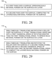
- Fig. 28 illustrates an example layering process 100 for a 3D printer, such as might be implemented through a controller 64 executing roller control instructions 66 in fusing system 10 in Fig. 27 .
- process 100 includes, in a first pass over a surface, spreading build material powder on the surface in a layer (block 102) and, in a second pass over the surface, compacting the layered build material powder on the surface.
- Fig. 29 illustrates another example layering process 110 for a 3D printer, such as might be implemented with a controller 64 executing roller control instructions 66 in fusing system 10 in Fig. 27 .
- process 110 includes simultaneously translating and rotating a roller over the surface at a first translational speed and with a first tangential speed of rotation greater than the first translational speed, to spread build material powder on the surface in a layer (block 112), and then simultaneously translating and rotating the roller over the surface at a second translational speed and with a second tangential speed of rotation less than the second translational speed, to compact the layered build material powder on the surface.
Description
- 3D printers produce objects by building up layers of material. 3D printers are also commonly referred to as additive manufacturing machines. 3D printers convert a CAD (computer aided design) model or other digital representation of an object into the physical object. The model data may be processed into slices each defining that part of a layer of build material to be formed into the object.
EP3401082A1 andWO2017/083734 disclose 3D printers comprising a roller to spread and compact layered powder material. -
-
Figs. 1-24 present a sequence of elevation and plan views showing a fusing system in a 3D printer implementing one example of a build material powder layering process. -
Figs. 25 and 26 are details fromFigs. 21 and23 , respectively. -
Fig. 27 is a block diagram illustrating an example fusing system such as the one shown inFigs. 1-24 . -
Figs. 28 and 29 are flow diagrams illustrating example build material powder layering processes such as might be implemented with a fusing system shown inFig. 27 . - The same part numbers designate the same or similar parts throughout the figures. The figures are not to scale. The scale of the layers of build material and object slices is greatly exaggerated in the figures. Each layer of build material in a fusing process such as that shown in
Figs. 1-24 may be on the order of tens of microns thick with thousands of layers to manufacture an object. - In some 3D printers, heat is used to fuse together particles in a powdered build material to form a solid object. Heat to fuse the build material may be generated, for example, by applying a liquid fusing agent to a thin layer of powdered build material in a pattern based on the object slice and then exposing the patterned area to fusing light. Light absorbing components in the fusing agent absorb light energy to help heat the patterned build material above a fusing temperature to sinter or melt and thus fuse the build material. Other liquid agents may be used to produce the desired characteristics of an object. For example, a detailing agent may be used to enhance or inhibit fusing in certain regions of an object and coloring agents may be used to color the object. The process is repeated layer by layer and slice by slice to complete the object.
- Spreading consistent, higher density layers of build material powder improves object quality. Lower density layers of powder can cause weak material properties and holes, craters or other defects in the object. One technique to increase layer density uses a "counter-rotating" roller to spread the build material powder. The roller is rotated into the direction of travel to push the powder across the work surface. Unfused powder in the underlying layers is easily disturbed when spreading the next layer of powder if the tangential speed of a counter-rotating roller is slower than the translational speed of the roller. Disturbing unfused powder in underlying layers is a particular problem when printing objects with specially colored surfaces because unfused powder treated with a liquid coloring agent may be dragged across the work surface and contaminate adjacent areas of the in-process structure
- A new layering technique has been developed to reduce the risk that unfused powder will be disturbed while forming the next layer of powder, while still delivering consistent, higher density layers. In one example, a process to layer build material powder in a 3D printer includes, in a first pass, spreading build material powder in a layer and, in a second pass, compacting the layered build material powder. For example, (1) the powder is spread in the first pass by pushing the powder across the work surface with a counter-rotating roller translating at a first translational speed and simultaneously rotating with a first tangential speed of rotation faster than the first translational speed and (2) the powder is compacted in the second pass by translating the roller over the layered powder at a second translational speed and simultaneously rotating the roller at a second tangential speed of rotation slower than the second translational speed. Rotating the roller faster in the first pass reduces compaction to lower the risk of disturbing unfused powder in the underlying layers. Rotating the roller slower in the second pass increases compaction for a higher density layer but with little risk of disturbing unfused powder in the underlying layers because the unfused powder has already been covered in the first pass.
- Examples of the new technique may also be useful for 3D printing techniques in which a binder applied to the build material is cured with light and/or heat to form a "green part" that is subsequently heated in a sintering furnace to form the final object. Accordingly, "fusing" as used in this document includes 3D printer binding as well as melting and sintering.
- These and other examples shown in the figures and described below illustrate but do not limit the scope of the patent, which is defined in the Claims following this Description.
- As used in this document: "and/or" means one or more of the connected things; "fusing" includes melting, sintering, and/or binding; a "memory" means any non-transitory tangible medium that can embody, contain, store, or maintain instructions and other information for use by a processor and may include, for example, circuits, integrated circuits, ASICs (application specific integrated circuits), hard drives, random access memory (RAM) and read-only memory (ROM); "work surface" means any suitable surface to support or contain build material for fusing, including underlying layers of build material and in-process slice and other object structures; and "tangential speed of rotation" means the tangential speed of a roller due to rotation only and does include tangential speed due to translation of the roller.
- In the figures: build material without any agent is depicted by light stippling; build material with only coloring agent is depicted by medium stippling; build material with only fusing agent is depicted by checked hatching; build material with coloring agent and fusing agent is depicted by dark stippling; and fused build material is depicted by regular cross hatching.
-
Figs. 1-24 present a sequence of elevation and plan views showing afusing system 10 for a 3D printer implementing one example of a new build material powder layering process.Fig. 27 is a block diagram illustrating afusing system 10 such as the one shown inFigs. 1-24 . Referring toFigs. 1, 2 and27 ,fusing system 10 includes a first, "fuser"carriage 12 and a second, "dispenser"carriage 14.Carriages rails 16 over awork surface 18. Fusercarriage 12 carries aroller 22, awarming lamp 24, and afusing lamp 26. "Warming" in this context refers to the preheating function ofwarming lamp 24 to help heat unfused build material to a temperature nearer the fusing temperature. Although a single warming lamp is shown, multiple warming lamps or otherradiant heating devices 24 could be used. Also, while asingle fusing lamp 26 is depicted, multiple fusing lamps may be used.Dispenser carriage 14 carries an inkjet printhead assembly or other suitableliquid dispensing assembly 28 to dispense a fusing agent.Assembly 28 may also dispense other agents. In this example,dispensing assembly 28 includes afirst dispenser 30 to dispense a coloring agent and asecond dispenser 32 to dispense a fusing agent. - As noted above in the definitions,
work surface 18 represents any suitable structure to support or contain build material for fusing, including underlying layers of build material and in-process slice and other object structures. For a first layer of build material, for example,work surface 18 may be formed on the surface of aplatform 34 that moves up and down to accommodate the layering process. For succeeding layers of build material,work surface 18 may be formed on anunderlying structure 36. InFig. 1 ,underlying structure 36 is a first layer ofbuild material powder 38. - In
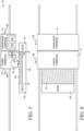
Figs. 1 and 2 , a pile ofbuild material 38 has been deposited along adeck 40 adjacent towork surface 18,roller 22 is deployed,warming lamp 24 is on, andfuser carriage 12 is moving to the right in a first layering pass, as indicated bymotion arrows 42. - In
Figs. 3 and 4 , asfuser carriage 12 continues moving to the right, warminglamp 24 heatsfirst layer 36 whileroller 22 spreadspowder 38 in alayer 44 overfirst layer 36. As described below with reference to the detail view ofFig. 25 , on thisfirst pass roller 22 is rotated at an angular velocity that results in a tangential speed of rotation faster than the translational speed ofroller 22, and in thesame direction 42 thatroller 22 is movingoverwork surface 18, as indicated byrotation arrow 46. - In
Figs. 5 and 6 ,fuser carriage 12 is moving to the left in a second layering pass, as indicated bymotion arrows 48.Roller 22 is deployed to compact build material inlayer 44 againstwork surface 18. As described in detail below with reference to the detail view ofFig. 26 , on thissecond pass roller 22 is rotated at an angular velocity that results in a tangential speed of rotation slower than the translational speed ofroller 22 and in thesame direction 48roller 22 is moving overwork surface 18, as indicated byrotation arrow 50.Warming lamp 24 is on to warm build material inlayer 44. - In
Figs. 7 and 8 ,dispenser carriage 14 followsfuser carriage 12 in the second pass withdispenser 30 dispensing acoloring agent 52 on to build material powder inlayer 44 to color the bottom surface of the object. -
Figs. 9-12 show a next (third)layer 54 spread and compacted on underlying (second)layer 44 in first and second layering passes. - In
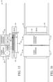
Figs. 13 and 14 ,dispenser carriage 14 followsfuser carriage 12 in the second pass withdispenser 30 dispensing acoloring agent 52 on to build material powder inlayer 54 across an area spanning the outer periphery of the object slice, to color the sides of the object. Also,dispenser 32 is dispensing afusing agent 56 in a pattern corresponding to the object slice. Theband 60 of dark stippling inFigs. 13 and 14 indicates the overlap where build material at the outer periphery of the object slice that is treated with both coloring agent and fusing agent. When fused, this band will form the colored outer surface of the object. - In
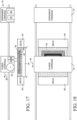
Figs. 15 and 16 dispenser carriage 14 is moving to the right in a first fusing pass withdispenser 32 dispensingadditional fusing agent 56 on to previously patterned and/or unpatterned build material inlayer 54.Fuser carriage 12 followsdispenser carriage 14 overwork surface 18 with fusinglamp 26 on to irradiatebuild material 54 with fusing light to fuse the build material patterned with fusingagent 56. The fused build material forms a first object slice shown by regular cross hatching in the figures. In this example, warminglamp 24 is on in the second pass, for example to slow the cooling of fused build material. - In
Figs. 17 and 18 ,dispenser carriage 14 is parked whilefuser carriage 12 moves to the left in a second fusing pass with warminglamp 24 and fusinglamp 26 on to irradiate fused build material 58. The nearly continuous exposure to both the heat from warminglamp 24 and the light from fusinglamp 26 in the second fusing pass helps keep build material fused in the first pass at or above the fusing temperature for more complete fusing. - The sequence then begins again to spread and compact the next (fourth)
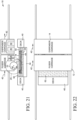
layer 62 of build material as shown inFigs. 19-24 . Layering and fusing continues layer by layer and slice by slice to complete the object. -
Figs. 25 and 26 are detail views fromFigs. 21 and23 , respectively. InFig. 25 ,roller 22 is moving right on the first layering pass, pushing build material powder acrosswork surface 18 to formlayer 62. InFig. 26 ,roller 22 is moving left in the second layering pass, compacting powder inlayer 62 againstwork surface 18. In this example, the axis of translation is the same for both passes. - Referring to
Fig. 25 ,roller 22 is carried overwork surface 18 from left to right at a translational speed VTR. Roller 22 is rotated counter-clockwise at an angular velocity ω that results in a tangential speed of rotation VTA in the same direction as VTR and greater than VTR. A VTA faster than the VTR in the same direction while spreadingpowder 38 in the first layering pass reduces drag alongwork surface 18 to lower the risk of disturbing unfused powder in the underlying layer(s). Testing indicates that, for a translational speed about 17 inches per second (43 cm/s) layering polyamide build material powder to a thickness of about 80µm, a ratio between the translational speed and the tangential speed of rotation (VTR/VTA) in the range of 1.0 to 0.7 spreads the powder without significantly disturbing unfused powder in the underlying layer(s). Thus, any compaction that may occur during a spreading pass will not adversely affect the underlying layer(s). Testing also indicates that faster rotational speeds resulting in VTR/VTA less than 0.7 entrain fine powder particles in the airflow around the roller and contaminate the surrounding environment. - Referring to
Fig. 26 ,roller 22 is carried overwork surface 18 right to left at a translational speed VTR. Roller 22 is rotated clockwise at an angular velocity ω that results in a tangential speed of rotation VTA in the same direction as VTR and less than VTR. A VTA slower than the VTR in the same direction moving over the already layered powder compacts the powder againstwork surface 18 without significantly disturbing unfused powder in the underlying layer(s). Testing indicates that, for translational speeds about 17 inches per second (43 cm/s) layering polyamide powder to a thickness of about 80µm, a ratio between the translational speed and the tangential speed of rotation (VTR/VTA) in the range of 1.0 to 2.0 on the second pass will compact the layered powder without significantly disturbing unfused powder in the underlying layer(s). Testing also indicates that the increased drag on underlying layers caused by slower rotational speeds with VTR/VTA greater than 2.0 can actually shift underlying structures, resulting in dimensional inaccuracies in the manufactured object. - While it is expected that the translational speed of
roller 22 usually will be the same in both passes, it may be desirable in some implementations to moveroller 22 overwork surface 18 at different translational speeds in the first and second passes. - Other processing and system sequences and configurations are possible. For example, while it is expected that the powder spreading and compacting passes usually will include an outbound and return pass of the roller across the work surface, it may be desirable in some implementations to spread and compact build material powder with the roller moving in the same direction across the work surface (rather than back and forth as shown). If multiple layering rollers are used, it may be possible to spread and compact the powder in a single pass with a leading roller spreading powder in a layer and a trailing roller compacting the powder. More or fewer agent dispensers may be used to dispense more or fewer agents, and more or fewer carriages could be used to carry the movable components. Also, the sequence of dispensing agents may vary from that shown and, although one carriage follows immediately after the other carriage in some passes, the carriages could be staggered as part of the same pass. In some system configurations, a stationary warmer and/or fusing lamp may be used to continuously irradiate the work surface with fusing light (except when blocked by a carriage), rather than intermittently as with carriage mounted components.
- Referring again to
Fig. 27 , fusingsystem 10 includes acontroller 64 programmed withroller control instructions 66.Controller 64 represents the processing and memory resources, programming, and the electronic circuitry and components needed to control the operative elements ofsystem 10. In particular,controller 64 includes amemory 68 withroller control instructions 66 and aprocessor 70 to read and executeinstructions 66, for example to implement the process shown inFigs.1-26 . -
Fig. 28 illustrates anexample layering process 100 for a 3D printer, such as might be implemented through acontroller 64 executingroller control instructions 66 in fusingsystem 10 inFig. 27 . Referring toFig. 27 ,process 100 includes, in a first pass over a surface, spreading build material powder on the surface in a layer (block 102) and, in a second pass over the surface, compacting the layered build material powder on the surface. -
Fig. 29 illustrates anotherexample layering process 110 for a 3D printer, such as might be implemented with acontroller 64 executingroller control instructions 66 in fusingsystem 10 inFig. 27 . Referring toFig. 28 ,process 110 includes simultaneously translating and rotating a roller over the surface at a first translational speed and with a first tangential speed of rotation greater than the first translational speed, to spread build material powder on the surface in a layer (block 112), and then simultaneously translating and rotating the roller over the surface at a second translational speed and with a second tangential speed of rotation less than the second translational speed, to compact the layered build material powder on the surface. - The examples shown in the figures and described above illustrate but do not limit the patent, which is defined in the following Claims.
Claims (14)
- A system for a 3D printer, comprising:a roller (22) to spread and compact build material powder (38) on a surface (18); anda controller (64) operatively connected to the roller and programmed to:simultaneously translate and rotate the roller over the surface at a first translational speed and with a first tangential speed of rotation greater than the first translational speed, to spread build material powder on the surface in a layer; and thensimultaneously translate and rotate the roller over the surface at a second translational speed and with a second tangential speed of rotation less than the second translational speed, to compact the layered build material powder on the surface.
- The system of claim 1, wherein the second translational speed is the same as the first translational speed.
- The system of claim 1, wherein the controller is programmed to:simultaneously translate and rotate the roller over the surface in a first pass at the first translational speed and with the first tangential speed of rotation to spread build material powder on the surface; and thensimultaneously translate and rotate the roller over the surface in a second pass at the second translational speed and with the second tangential speed of rotation to compact the build material powder on the surface.
- The system of claim 3, wherein the controller is programmed to:simultaneously translate and rotate the roller over the surface in the first pass at the first translational speed in a first direction and with the first tangential speed of rotation in the first direction; and thensimultaneously translate and rotate the roller over the surface in the second pass at the second translational speed in a second direction opposite the first direction and with the second tangential speed of rotation in the second direction.
- The system of claim 1, wherein:a ratio between the first translational speed and the first tangential speed of rotation is in the range of 1.0 to 0.7, excluding 1.0; anda ratio between the second translational speed and the second tangential speed of rotation is in the range of 1.0 to 2.0, excluding 1.0.
- The system of claim 3, wherein the roller is translatable along an axis and the axis of translation is the same for both passes.
- The system of claim 1, wherein the roller is a counter-rotating roller to rotate into the direction of travel to push powder across the surface.
- A process to layer build material powder on a surface in a 3D printer, comprising:in a first pass over the surface, spreading (102) build material powder on the surface in a layer comprising pushing the build material powder across the surface with a roller translating at a first translational speed and simultaneously rotating with a first tangential speed of rotation greater than the first translational speed; andin a second pass over the surface, compacting (104) the layered build material powder on the surface comprising translating the roller over the layered build material powder at a second translational speed and simultaneously rotating the roller at a second tangential speed of rotation less than the second translational speed.
- The process of claim 8, wherein:a ratio between the first translational speed and the first tangential speed of rotation is in the range of 1.0 to 0.7, excluding 1.0; anda ratio between the second translational speed and the second tangential speed of rotation is in the range of 1.0 to 2.0, excluding 1.0.
- The process of claim 9, wherein the second translational speed is the same as the first translational speed.
- A memory having processor readable instructions to, in a 3D printer comprising a system comprising a single roller:in a first pass, spread build material powder over a surface with the single roller, including:translate the single roller in a first direction at a first translational speed; androtate the translating single roller at a first rotational velocity that results in a first tangential speed of rotation in the first direction greater than the first translational speed; andin a second pass, compact the build material powder on the surface with the single roller, including:translate the single roller in a second direction opposite the first direction at a second translational speed; androtate the translating single roller at a second rotational velocity that results in a second tangential speed of rotation in the second direction less than the second translational speed.
- The memory of claim 11, wherein:a ratio between the first translational speed and the first tangential speed of rotation is in the range of 1.0 to 0.7, excluding 1.0; anda ratio between the second translational speed and the second tangential speed of rotation is in the range of 1.0 to 2.0, excluding 1.0.
- The memory of claim 11, wherein the second translational speed is same as the first translational speed.
- A 3D printer controller implementing the memory of claim 11.
Applications Claiming Priority (1)
| Application Number | Priority Date | Filing Date | Title |
|---|---|---|---|
| PCT/US2019/038937 WO2020263227A1 (en) | 2019-06-25 | 2019-06-25 | Roller control for a 3d printer |
Publications (3)
| Publication Number | Publication Date |
|---|---|
| EP3911496A1 EP3911496A1 (en) | 2021-11-24 |
| EP3911496A4 EP3911496A4 (en) | 2022-08-17 |
| EP3911496B1 true EP3911496B1 (en) | 2024-01-03 |
Family
ID=74062021
Family Applications (1)
| Application Number | Title | Priority Date | Filing Date |
|---|---|---|---|
| EP19935448.1A Active EP3911496B1 (en) | 2019-06-25 | 2019-06-25 | Roller control for a 3d printer |
Country Status (4)
| Country | Link |
|---|---|
| US (1) | US20220126512A1 (en) |
| EP (1) | EP3911496B1 (en) |
| CN (1) | CN113518703B (en) |
| WO (1) | WO2020263227A1 (en) |
Family Cites Families (14)
| Publication number | Priority date | Publication date | Assignee | Title |
|---|---|---|---|---|
| ATE216951T1 (en) * | 1995-02-01 | 2002-05-15 | 3D Systems Inc | FAST SMOOTHING PROCESS FOR THREE-DIMENSIONAL OBJECTS PRODUCED IN LAYERS |
| FR2948044B1 (en) * | 2009-07-15 | 2014-02-14 | Phenix Systems | THIN-LAYERING DEVICE AND METHOD OF USING SUCH A DEVICE |
| WO2014138386A1 (en) * | 2013-03-06 | 2014-09-12 | University Of Louisville Research Foundation, Inc. | Powder bed fusion systems, apparatus, and processes for multi-material part production |
| TW201536531A (en) * | 2014-03-19 | 2015-10-01 | Univ Nat Cheng Kung | Method and device for increasing the strength of additive manufacturing product |
| FR3021568A1 (en) * | 2014-05-28 | 2015-12-04 | Phenix Systems | PROCESS FOR PRODUCING A THREE DIMENSIONAL OBJECT BY SOLIDIFYING POWDER |
| US20150367418A1 (en) * | 2014-06-20 | 2015-12-24 | Velo3D, Inc. | Apparatuses, systems and methods for three-dimensional printing |
| MX2018005954A (en) * | 2015-11-13 | 2019-01-31 | Paxis Llc | Additive manufacturing apparatus, system, and method. |
| US10913259B2 (en) * | 2015-11-20 | 2021-02-09 | Ricoh Company, Ltd. | Three-dimensional shaping apparatus and three-dimensional shaping system |
| BE1024613B1 (en) * | 2016-09-29 | 2018-05-02 | Aerosint Sa | Device and method for creating a particle structure |
| US11179777B2 (en) * | 2017-05-11 | 2021-11-23 | Ricoh Company, Ltd. | Device for fabricating three-dimensional fabrication object and method of manufacturing three-dimensional fabrication object |
| CN107900285A (en) * | 2017-10-20 | 2018-04-13 | 沈阳铸造研究所 | The consolidation method of 3D printing casting sand type |
| US10926356B2 (en) * | 2018-08-08 | 2021-02-23 | Robert Bosch Gmbh | System and method for powder bed fusion additive manufacturing with dynamic roller rotational speed adjustment |
| JPWO2020044522A1 (en) * | 2018-08-30 | 2021-08-10 | 株式会社アスペクト | Powder bed melt coupling device |
| CN114555266A (en) * | 2019-05-23 | 2022-05-27 | 通用电气公司 | Additive manufacturing apparatus and method |
-
2019
- 2019-06-25 CN CN201980093647.4A patent/CN113518703B/en active Active
- 2019-06-25 US US17/431,351 patent/US20220126512A1/en active Pending
- 2019-06-25 EP EP19935448.1A patent/EP3911496B1/en active Active
- 2019-06-25 WO PCT/US2019/038937 patent/WO2020263227A1/en unknown
Also Published As
| Publication number | Publication date |
|---|---|
| EP3911496A1 (en) | 2021-11-24 |
| EP3911496A4 (en) | 2022-08-17 |
| US20220126512A1 (en) | 2022-04-28 |
| CN113518703A (en) | 2021-10-19 |
| CN113518703B (en) | 2023-04-04 |
| WO2020263227A1 (en) | 2020-12-30 |
Similar Documents
| Publication | Publication Date | Title |
|---|---|---|
| US11654626B2 (en) | Additive manufacturing | |
| EP1648686B2 (en) | Method and apparatus for selective sintering of particulate material | |
| EP1735133B1 (en) | Apparatus and method for three dimensional printing using imaged layers | |
| EP3362256B1 (en) | Build material supply for additive manufacturing | |
| EP3389994B1 (en) | Definition of a shield feature for additive manufacture | |
| WO2016010536A1 (en) | Consolidating a build material substrate for additive manufacturing | |
| EP3233425B1 (en) | Additive manufacturing | |
| KR102266754B1 (en) | Deviation Control in Additive Manufacturing | |
| JP3236526U (en) | Thread configuration and operation method for manufacturing 3D objects | |
| WO2020222759A1 (en) | Determining liquid agent amounts in 3d printing | |
| EP3911496B1 (en) | Roller control for a 3d printer | |
| US11559939B2 (en) | Dispensing powdered build material for additive manufacturing | |
| US20200238608A1 (en) | Additive manufacturing layers | |
| CN110325345B (en) | Additive manufacturing | |
| WO2018182629A1 (en) | 3d object part section formation | |
| US11214010B2 (en) | Roller control for a 3D printer | |
| EP3245041A1 (en) | Additive manufacturing | |
| EP3762215B1 (en) | Additive manufacturing |
Legal Events
| Date | Code | Title | Description |
|---|---|---|---|
| STAA | Information on the status of an ep patent application or granted ep patent |
Free format text: STATUS: THE INTERNATIONAL PUBLICATION HAS BEEN MADE |
|
| PUAI | Public reference made under article 153(3) epc to a published international application that has entered the european phase |
Free format text: ORIGINAL CODE: 0009012 |
|
| STAA | Information on the status of an ep patent application or granted ep patent |
Free format text: STATUS: REQUEST FOR EXAMINATION WAS MADE |
|
| 17P | Request for examination filed |
Effective date: 20210816 |
|
| AK | Designated contracting states |
Kind code of ref document: A1 Designated state(s): AL AT BE BG CH CY CZ DE DK EE ES FI FR GB GR HR HU IE IS IT LI LT LU LV MC MK MT NL NO PL PT RO RS SE SI SK SM TR |
|
| A4 | Supplementary search report drawn up and despatched |
Effective date: 20220714 |
|
| RIC1 | Information provided on ipc code assigned before grant |
Ipc: B29C 64/241 20170101ALI20220708BHEP Ipc: B29C 64/236 20170101ALI20220708BHEP Ipc: B22F 12/63 20210101ALI20220708BHEP Ipc: B22F 10/37 20210101ALI20220708BHEP Ipc: B33Y 30/00 20150101ALI20220708BHEP Ipc: B29C 64/393 20170101ALI20220708BHEP Ipc: B29C 64/218 20170101ALI20220708BHEP Ipc: B29C 64/20 20170101AFI20220708BHEP |
|
| DAV | Request for validation of the european patent (deleted) | ||
| DAX | Request for extension of the european patent (deleted) | ||
| GRAP | Despatch of communication of intention to grant a patent |
Free format text: ORIGINAL CODE: EPIDOSNIGR1 |
|
| STAA | Information on the status of an ep patent application or granted ep patent |
Free format text: STATUS: GRANT OF PATENT IS INTENDED |
|
| INTG | Intention to grant announced |
Effective date: 20230406 |
|
| GRAJ | Information related to disapproval of communication of intention to grant by the applicant or resumption of examination proceedings by the epo deleted |
Free format text: ORIGINAL CODE: EPIDOSDIGR1 |
|
| STAA | Information on the status of an ep patent application or granted ep patent |
Free format text: STATUS: REQUEST FOR EXAMINATION WAS MADE |
|
| INTC | Intention to grant announced (deleted) | ||
| GRAP | Despatch of communication of intention to grant a patent |
Free format text: ORIGINAL CODE: EPIDOSNIGR1 |
|
| STAA | Information on the status of an ep patent application or granted ep patent |
Free format text: STATUS: GRANT OF PATENT IS INTENDED |
|
| INTG | Intention to grant announced |
Effective date: 20230828 |
|
| GRAS | Grant fee paid |
Free format text: ORIGINAL CODE: EPIDOSNIGR3 |
|
| GRAA | (expected) grant |
Free format text: ORIGINAL CODE: 0009210 |
|
| STAA | Information on the status of an ep patent application or granted ep patent |
Free format text: STATUS: THE PATENT HAS BEEN GRANTED |
|
| AK | Designated contracting states |
Kind code of ref document: B1 Designated state(s): AL AT BE BG CH CY CZ DE DK EE ES FI FR GB GR HR HU IE IS IT LI LT LU LV MC MK MT NL NO PL PT RO RS SE SI SK SM TR |
|
| REG | Reference to a national code |
Ref country code: GB Ref legal event code: FG4D |
|
| REG | Reference to a national code |
Ref country code: CH Ref legal event code: EP |
|
| REG | Reference to a national code |
Ref country code: DE Ref legal event code: R096 Ref document number: 602019044715 Country of ref document: DE |
|
| REG | Reference to a national code |
Ref country code: IE Ref legal event code: FG4D |