EP3911282B1 - Method for controlling an orthotic or prosthetic device and orthotic or prosthetic device - Google Patents
Method for controlling an orthotic or prosthetic device and orthotic or prosthetic device Download PDFInfo
- Publication number
- EP3911282B1 EP3911282B1 EP20701023.2A EP20701023A EP3911282B1 EP 3911282 B1 EP3911282 B1 EP 3911282B1 EP 20701023 A EP20701023 A EP 20701023A EP 3911282 B1 EP3911282 B1 EP 3911282B1
- Authority
- EP
- European Patent Office
- Prior art keywords
- muscle
- contraction
- orthotic
- movement
- detection device
- Prior art date
- Legal status (The legal status is an assumption and is not a legal conclusion. Google has not performed a legal analysis and makes no representation as to the accuracy of the status listed.)
- Active
Links
- 238000000034 method Methods 0.000 title claims description 38
- 210000003205 muscle Anatomy 0.000 claims description 90
- 230000033001 locomotion Effects 0.000 claims description 86
- 238000001514 detection method Methods 0.000 claims description 61
- 230000001965 increasing effect Effects 0.000 claims description 28
- 238000007781 pre-processing Methods 0.000 claims description 26
- 230000004118 muscle contraction Effects 0.000 claims description 22
- 230000008859 change Effects 0.000 claims description 20
- 230000008569 process Effects 0.000 claims description 12
- 230000002829 reductive effect Effects 0.000 claims description 12
- 230000001133 acceleration Effects 0.000 claims description 9
- 230000003183 myoelectrical effect Effects 0.000 claims description 7
- 239000007943 implant Substances 0.000 claims description 6
- 230000003287 optical effect Effects 0.000 claims description 5
- 230000002747 voluntary effect Effects 0.000 claims description 4
- 210000002027 skeletal muscle Anatomy 0.000 claims description 3
- 210000002460 smooth muscle Anatomy 0.000 claims description 3
- 230000003247 decreasing effect Effects 0.000 claims description 2
- 210000000689 upper leg Anatomy 0.000 description 25
- 210000000629 knee joint Anatomy 0.000 description 24
- 210000002683 foot Anatomy 0.000 description 13
- 238000013016 damping Methods 0.000 description 11
- 230000008602 contraction Effects 0.000 description 10
- 210000003414 extremity Anatomy 0.000 description 10
- 210000003127 knee Anatomy 0.000 description 9
- 210000000544 articulatio talocruralis Anatomy 0.000 description 6
- 239000005557 antagonist Substances 0.000 description 5
- 230000000694 effects Effects 0.000 description 5
- 210000003141 lower extremity Anatomy 0.000 description 5
- 238000012545 processing Methods 0.000 description 5
- 210000001364 upper extremity Anatomy 0.000 description 5
- 230000004913 activation Effects 0.000 description 4
- 238000005452 bending Methods 0.000 description 4
- 239000000556 agonist Substances 0.000 description 3
- 230000007423 decrease Effects 0.000 description 3
- 230000005021 gait Effects 0.000 description 3
- 210000002414 leg Anatomy 0.000 description 3
- 210000003489 abdominal muscle Anatomy 0.000 description 2
- 230000003213 activating effect Effects 0.000 description 2
- 210000003423 ankle Anatomy 0.000 description 2
- 230000008901 benefit Effects 0.000 description 2
- 230000001419 dependent effect Effects 0.000 description 2
- 238000013461 design Methods 0.000 description 2
- 238000011161 development Methods 0.000 description 2
- 230000018109 developmental process Effects 0.000 description 2
- 238000004146 energy storage Methods 0.000 description 2
- 230000000399 orthopedic effect Effects 0.000 description 2
- 210000003314 quadriceps muscle Anatomy 0.000 description 2
- 230000011514 reflex Effects 0.000 description 2
- 230000000717 retained effect Effects 0.000 description 2
- 241001465754 Metazoa Species 0.000 description 1
- 208000003443 Unconsciousness Diseases 0.000 description 1
- 230000002411 adverse Effects 0.000 description 1
- 230000003042 antagnostic effect Effects 0.000 description 1
- 230000004071 biological effect Effects 0.000 description 1
- 230000005540 biological transmission Effects 0.000 description 1
- 230000002925 chemical effect Effects 0.000 description 1
- 230000008878 coupling Effects 0.000 description 1
- 238000010168 coupling process Methods 0.000 description 1
- 238000005859 coupling reaction Methods 0.000 description 1
- 238000005516 engineering process Methods 0.000 description 1
- 230000007613 environmental effect Effects 0.000 description 1
- 238000011156 evaluation Methods 0.000 description 1
- 238000004880 explosion Methods 0.000 description 1
- 239000012530 fluid Substances 0.000 description 1
- 210000004744 fore-foot Anatomy 0.000 description 1
- 210000000245 forearm Anatomy 0.000 description 1
- 210000001624 hip Anatomy 0.000 description 1
- 210000004394 hip joint Anatomy 0.000 description 1
- 230000001939 inductive effect Effects 0.000 description 1
- 210000001503 joint Anatomy 0.000 description 1
- 208000018883 loss of balance Diseases 0.000 description 1
- 230000007246 mechanism Effects 0.000 description 1
- 230000003387 muscular Effects 0.000 description 1
- 238000003909 pattern recognition Methods 0.000 description 1
- 230000000704 physical effect Effects 0.000 description 1
- 238000002360 preparation method Methods 0.000 description 1
- 230000002035 prolonged effect Effects 0.000 description 1
- 230000002441 reversible effect Effects 0.000 description 1
- 238000010561 standard procedure Methods 0.000 description 1
- 239000000126 substance Substances 0.000 description 1
- 239000013589 supplement Substances 0.000 description 1
- 230000002123 temporal effect Effects 0.000 description 1
- 238000011144 upstream manufacturing Methods 0.000 description 1
Images


Classifications
-
- A—HUMAN NECESSITIES
- A61—MEDICAL OR VETERINARY SCIENCE; HYGIENE
- A61F—FILTERS IMPLANTABLE INTO BLOOD VESSELS; PROSTHESES; DEVICES PROVIDING PATENCY TO, OR PREVENTING COLLAPSING OF, TUBULAR STRUCTURES OF THE BODY, e.g. STENTS; ORTHOPAEDIC, NURSING OR CONTRACEPTIVE DEVICES; FOMENTATION; TREATMENT OR PROTECTION OF EYES OR EARS; BANDAGES, DRESSINGS OR ABSORBENT PADS; FIRST-AID KITS
- A61F2/00—Filters implantable into blood vessels; Prostheses, i.e. artificial substitutes or replacements for parts of the body; Appliances for connecting them with the body; Devices providing patency to, or preventing collapsing of, tubular structures of the body, e.g. stents
- A61F2/50—Prostheses not implantable in the body
- A61F2/60—Artificial legs or feet or parts thereof
- A61F2/64—Knee joints
-
- A—HUMAN NECESSITIES
- A61—MEDICAL OR VETERINARY SCIENCE; HYGIENE
- A61B—DIAGNOSIS; SURGERY; IDENTIFICATION
- A61B5/00—Measuring for diagnostic purposes; Identification of persons
- A61B5/103—Detecting, measuring or recording devices for testing the shape, pattern, colour, size or movement of the body or parts thereof, for diagnostic purposes
- A61B5/11—Measuring movement of the entire body or parts thereof, e.g. head or hand tremor, mobility of a limb
- A61B5/1107—Measuring contraction of parts of the body, e.g. organ, muscle
-
- A—HUMAN NECESSITIES
- A61—MEDICAL OR VETERINARY SCIENCE; HYGIENE
- A61B—DIAGNOSIS; SURGERY; IDENTIFICATION
- A61B5/00—Measuring for diagnostic purposes; Identification of persons
- A61B5/103—Detecting, measuring or recording devices for testing the shape, pattern, colour, size or movement of the body or parts thereof, for diagnostic purposes
- A61B5/11—Measuring movement of the entire body or parts thereof, e.g. head or hand tremor, mobility of a limb
- A61B5/1121—Determining geometric values, e.g. centre of rotation or angular range of movement
-
- A—HUMAN NECESSITIES
- A61—MEDICAL OR VETERINARY SCIENCE; HYGIENE
- A61B—DIAGNOSIS; SURGERY; IDENTIFICATION
- A61B5/00—Measuring for diagnostic purposes; Identification of persons
- A61B5/48—Other medical applications
- A61B5/4851—Prosthesis assessment or monitoring
-
- A—HUMAN NECESSITIES
- A61—MEDICAL OR VETERINARY SCIENCE; HYGIENE
- A61F—FILTERS IMPLANTABLE INTO BLOOD VESSELS; PROSTHESES; DEVICES PROVIDING PATENCY TO, OR PREVENTING COLLAPSING OF, TUBULAR STRUCTURES OF THE BODY, e.g. STENTS; ORTHOPAEDIC, NURSING OR CONTRACEPTIVE DEVICES; FOMENTATION; TREATMENT OR PROTECTION OF EYES OR EARS; BANDAGES, DRESSINGS OR ABSORBENT PADS; FIRST-AID KITS
- A61F2/00—Filters implantable into blood vessels; Prostheses, i.e. artificial substitutes or replacements for parts of the body; Appliances for connecting them with the body; Devices providing patency to, or preventing collapsing of, tubular structures of the body, e.g. stents
- A61F2/50—Prostheses not implantable in the body
- A61F2/60—Artificial legs or feet or parts thereof
-
- A—HUMAN NECESSITIES
- A61—MEDICAL OR VETERINARY SCIENCE; HYGIENE
- A61F—FILTERS IMPLANTABLE INTO BLOOD VESSELS; PROSTHESES; DEVICES PROVIDING PATENCY TO, OR PREVENTING COLLAPSING OF, TUBULAR STRUCTURES OF THE BODY, e.g. STENTS; ORTHOPAEDIC, NURSING OR CONTRACEPTIVE DEVICES; FOMENTATION; TREATMENT OR PROTECTION OF EYES OR EARS; BANDAGES, DRESSINGS OR ABSORBENT PADS; FIRST-AID KITS
- A61F2/00—Filters implantable into blood vessels; Prostheses, i.e. artificial substitutes or replacements for parts of the body; Appliances for connecting them with the body; Devices providing patency to, or preventing collapsing of, tubular structures of the body, e.g. stents
- A61F2/50—Prostheses not implantable in the body
- A61F2/68—Operating or control means
- A61F2/70—Operating or control means electrical
- A61F2/72—Bioelectric control, e.g. myoelectric
-
- A—HUMAN NECESSITIES
- A61—MEDICAL OR VETERINARY SCIENCE; HYGIENE
- A61F—FILTERS IMPLANTABLE INTO BLOOD VESSELS; PROSTHESES; DEVICES PROVIDING PATENCY TO, OR PREVENTING COLLAPSING OF, TUBULAR STRUCTURES OF THE BODY, e.g. STENTS; ORTHOPAEDIC, NURSING OR CONTRACEPTIVE DEVICES; FOMENTATION; TREATMENT OR PROTECTION OF EYES OR EARS; BANDAGES, DRESSINGS OR ABSORBENT PADS; FIRST-AID KITS
- A61F2/00—Filters implantable into blood vessels; Prostheses, i.e. artificial substitutes or replacements for parts of the body; Appliances for connecting them with the body; Devices providing patency to, or preventing collapsing of, tubular structures of the body, e.g. stents
- A61F2/50—Prostheses not implantable in the body
- A61F2/78—Means for protecting prostheses or for attaching them to the body, e.g. bandages, harnesses, straps, or stockings for the limb stump
- A61F2/80—Sockets, e.g. of suction type
-
- G—PHYSICS
- G16—INFORMATION AND COMMUNICATION TECHNOLOGY [ICT] SPECIALLY ADAPTED FOR SPECIFIC APPLICATION FIELDS
- G16H—HEALTHCARE INFORMATICS, i.e. INFORMATION AND COMMUNICATION TECHNOLOGY [ICT] SPECIALLY ADAPTED FOR THE HANDLING OR PROCESSING OF MEDICAL OR HEALTHCARE DATA
- G16H40/00—ICT specially adapted for the management or administration of healthcare resources or facilities; ICT specially adapted for the management or operation of medical equipment or devices
- G16H40/60—ICT specially adapted for the management or administration of healthcare resources or facilities; ICT specially adapted for the management or operation of medical equipment or devices for the operation of medical equipment or devices
- G16H40/63—ICT specially adapted for the management or administration of healthcare resources or facilities; ICT specially adapted for the management or operation of medical equipment or devices for the operation of medical equipment or devices for local operation
-
- A—HUMAN NECESSITIES
- A61—MEDICAL OR VETERINARY SCIENCE; HYGIENE
- A61F—FILTERS IMPLANTABLE INTO BLOOD VESSELS; PROSTHESES; DEVICES PROVIDING PATENCY TO, OR PREVENTING COLLAPSING OF, TUBULAR STRUCTURES OF THE BODY, e.g. STENTS; ORTHOPAEDIC, NURSING OR CONTRACEPTIVE DEVICES; FOMENTATION; TREATMENT OR PROTECTION OF EYES OR EARS; BANDAGES, DRESSINGS OR ABSORBENT PADS; FIRST-AID KITS
- A61F2/00—Filters implantable into blood vessels; Prostheses, i.e. artificial substitutes or replacements for parts of the body; Appliances for connecting them with the body; Devices providing patency to, or preventing collapsing of, tubular structures of the body, e.g. stents
- A61F2/50—Prostheses not implantable in the body
- A61F2002/5038—Hinged joint, e.g. with transverse axle restricting the movement
-
- A—HUMAN NECESSITIES
- A61—MEDICAL OR VETERINARY SCIENCE; HYGIENE
- A61F—FILTERS IMPLANTABLE INTO BLOOD VESSELS; PROSTHESES; DEVICES PROVIDING PATENCY TO, OR PREVENTING COLLAPSING OF, TUBULAR STRUCTURES OF THE BODY, e.g. STENTS; ORTHOPAEDIC, NURSING OR CONTRACEPTIVE DEVICES; FOMENTATION; TREATMENT OR PROTECTION OF EYES OR EARS; BANDAGES, DRESSINGS OR ABSORBENT PADS; FIRST-AID KITS
- A61F2/00—Filters implantable into blood vessels; Prostheses, i.e. artificial substitutes or replacements for parts of the body; Appliances for connecting them with the body; Devices providing patency to, or preventing collapsing of, tubular structures of the body, e.g. stents
- A61F2/50—Prostheses not implantable in the body
- A61F2/68—Operating or control means
- A61F2002/6818—Operating or control means for braking
-
- A—HUMAN NECESSITIES
- A61—MEDICAL OR VETERINARY SCIENCE; HYGIENE
- A61F—FILTERS IMPLANTABLE INTO BLOOD VESSELS; PROSTHESES; DEVICES PROVIDING PATENCY TO, OR PREVENTING COLLAPSING OF, TUBULAR STRUCTURES OF THE BODY, e.g. STENTS; ORTHOPAEDIC, NURSING OR CONTRACEPTIVE DEVICES; FOMENTATION; TREATMENT OR PROTECTION OF EYES OR EARS; BANDAGES, DRESSINGS OR ABSORBENT PADS; FIRST-AID KITS
- A61F2/00—Filters implantable into blood vessels; Prostheses, i.e. artificial substitutes or replacements for parts of the body; Appliances for connecting them with the body; Devices providing patency to, or preventing collapsing of, tubular structures of the body, e.g. stents
- A61F2/50—Prostheses not implantable in the body
- A61F2/68—Operating or control means
- A61F2/70—Operating or control means electrical
- A61F2002/704—Operating or control means electrical computer-controlled, e.g. robotic control
-
- A—HUMAN NECESSITIES
- A61—MEDICAL OR VETERINARY SCIENCE; HYGIENE
- A61H—PHYSICAL THERAPY APPARATUS, e.g. DEVICES FOR LOCATING OR STIMULATING REFLEX POINTS IN THE BODY; ARTIFICIAL RESPIRATION; MASSAGE; BATHING DEVICES FOR SPECIAL THERAPEUTIC OR HYGIENIC PURPOSES OR SPECIFIC PARTS OF THE BODY
- A61H3/00—Appliances for aiding patients or disabled persons to walk about
Definitions
- the invention relates to a method for controlling an orthotic or prosthetic device as defined in the claims.
- the invention also relates to such an orthotic or prosthetic device as defined in the claims.
- the task of prosthetic devices or orthoses is to guide or support the movement of an existing limb, or to support and support a limb.
- Exoskeletons are also orthotic devices.
- Orthotic devices for the lower extremities are known in different embodiments, so-called KAFO (knee ankle foot orthosis) support both the foot and the ankle joint and the knee joint.
- the foot is usually placed on a footplate, one or more lower leg splints extend parallel to the lower leg and an orthotic knee joint is provided approximately in the area of the natural knee axis.
- Fastening devices for fixing the orthosis on the thigh are attached to one or more thigh splints.
- Fastening devices can also be provided on the lower leg or the foot plate in order to be able to fix the orthosis on the leg to be treated.
- the thigh splint is a proximal component and the lower leg splint is a distal component;
- the foot part is the distal component and the lower leg splint or splints is the proximal component.
- Dampers or drives can be arranged as actuators between the respective components in order to sequence movements influence and change resistance to movement. Either an increased resistance to movement for dampening a movement or a reduced resistance to movement by reducing damping or support can be provided by means of one or more motorized or stored-energy drives. The same applies to orthotic devices such as orthoses and exoskeletons for the upper extremity.
- Prostheses replace a missing limb and may include an artificial joint.
- Prostheses of the lower extremity can have a prosthetic knee joint, for example, which is connected to a prosthetic foot as a foot part via a lower leg tube as the lower leg part.
- a prosthetic ankle joint can be formed between the prosthetic foot and the lower leg tube.
- the prosthetic knee joint generally has an upper part and a lower part, which are mounted pivotably on one another either via a monocentric or polycentric joint device, so that the upper part can be pivoted about a pivot axis relative to the lower part.
- At least one fastening device is arranged on the upper part in order to be able to fix the prosthesis of the lower extremity on a user, for example for a femoral socket or in the form of a femoral socket.
- the lower leg tube is the upper part and the prosthetic foot is the lower part.
- An actuator can be arranged between the respective upper part and the lower part or the proximal component and the distal component in order to change the respective movement resistance with regard to flexion and/or extension.
- the movement resistance can be increased or reduced via the actuator, for example via passive, adjustable dampers or drives such as electric motors or drives driven by energy storage.
- corresponding prostheses are also known for the upper extremities.
- the features of an orthosis, prostheses or exoskeletons described above can also be present on the orthotic and prosthetic devices according to the invention.
- a method for controlling an orthotic or prosthetic joint with a resistance device and sensors is known, status information being provided via the sensors during use of the joint.
- the sensors record torques or forces, with the sensor data from at least two of the variables determined being linked to one another by a mathematical operation, thereby calculating an auxiliary variable on which the control of the flexion resistance and/or the extension resistance is based.
- Electrodes to detect a user's muscle contractions, for example surface electrodes or implanted electrodes, in order to generate control commands based on the detected muscle contractions, e.g. to activate or deactivate drives.
- Such controls based on myoelectric signals are used in particular in prostheses of the upper extremity in order to control complex movements of the prosthetic hand.
- Orthotic or prosthetic devices of the lower extremities are mainly influenced by the movements and loads of the body or the orthotic or prosthetic device, the accelerations or forces or states that occur are detected by sensors and a specific damping behavior is set based on the sensor signals. A willful influence is only possible by changing the movements or system loads.
- active, powered orthotic or prosthetic devices it is known to shift components relative to one another by proportionally allocating muscle activity to the drive, for example opening or closing a hand or controlling specific programs via pattern recognition. Contraction signals are sensed to toggle between different modes of operation.
- the DE 10 2015 001 967 A1 describes a controllable orthopedic device that is controlled, for example, by detecting muscle contractions.
- the DE 10 2017 119 490 B1 relates to a method for checking the functionality of a prosthesis system. Both documents deal only with the detection of muscle contractions.
- the DE 195 21 464 A1 relates to a method for controlling a knee brake of a prosthetic knee joint, in which case EMG sensors can be arranged on a plurality of muscles associated with the hip joint. The contraction of these muscles is used to control the knee brake.
- the object of the present invention is to provide users with an orthotic or prosthetic device and a method for controlling it, which provide increased safety for the user, while at the same time being simple to implement at the lowest possible cost.
- the method for controlling an orthotic or prosthetic device that can be placed on a user's body and fixed thereto, having a joint device with a proximal component and a distal component that are pivotably mounted on one another about a pivot axis, at least one adjustable actuator that is connected between between the proximal component and the distal component and via which a resistance to movement against pivoting of the proximal component relative to the distal component can be adjusted, at least one detection device for detecting muscle contractions and a control device, which is coupled to the detection device and the actuator, signals processed by the detection device and the actuator adjusted depending on the signals, provides that the detection device is set up to detect muscle co-contractions and at a The user's limb is arranged and coupled to the control device, that at least one muscle co-contraction is detected by the detection device, that it is determined whether a co-contraction is present and that the movement resistance of the actuator is changed depending on the detected muscle co-contraction.
- Muscle co-contraction is the tensing of agonists and antagonists to stabilize the joint, or the simultaneous tensing of two opposing muscles or muscle groups.
- a muscle co-contraction occurs, for example, when the arm biceps and triceps are contracted simultaneously without the forearm moving relative to the upper arm or, depending on the level of contraction, moving more slowly than without the antagonist contracting. The same applies to the muscles that stretch and bend the lower leg. If opposing muscles or muscle groups are contracted at the same time, this is called muscle co-contraction.
- Muscle co-contractions are used to stabilize joints or limbs, to have maximum control when performing movements, or to stop movements. Muscle co-contractions occur consciously or unconsciously.
- An unconscious co-contraction occurs, for example, as a reflex in the event of sudden disturbances, such as slippery surfaces, slippery ground, frightening situations such as explosions, accidents or the like, or in preparation for potentially dangerous situations, such as walking along an abyss or over a bridge.
- the basic tension in the muscular system is increased via a muscle co-contraction.
- the detection device detects a corresponding muscle co-contraction, for example if the arm biceps and arm triceps or the musculus biceps femoris and the musculus quadriceps femoris are simultaneously contracted by the detection device, corresponding signals are transmitted by the detection device to the control device, which then changes the movement resistance of the actuator depending on the detected muscle co-contractions.
- the movement resistance can be changed, for example, by adjusting valves in a hydraulic damper or a pneumatic damper.
- brakes can be released or activated or other resistances can be increased or reduced, for example via electric drives that are switched on or off or by shifting the proximal component relative to the distal one component counteracts.
- the basic setting of the actuator preferably remains unchanged, which means that once the resistance curve or a resistance course has been set, it is maintained over a specific movement or a specific load, ie the basic resistance behavior remains unchanged over the movement.
- selected muscles in particular muscles that are responsible for executing the respective movement or would be responsible if the limb were still present, the muscle activity is detected via the detection device.
- muscle co-contractions are not set to toggle and engage a new mode of operation, for example to switch from hand open mode to hand close mode of operation, rather the same movements are still allowed but at a different resistance level or resistance is increased to such an extent that further movement of the joint is no longer possible under normal load scenarios. It is therefore a variation of an original control behavior based on the detected co-contraction.
- the duration and/or the intensity of the muscle co-contraction or muscle co-contractions are recorded and the movement resistance is changed depending on the duration and/or the intensity of the muscle co-contraction or muscle co-contractions. For example, in the case of a prolonged muscle co-contraction, the resistance to movement is changed over a longer period of time. Likewise, with a high muscle co-contraction intensity, an increase in the change amplitude can be carried out compared to a lower muscle co-contraction intensity in order to change the movement resistance appropriately. For example, the resistance to movement can be increased upon detection of a muscle co-contraction, which corresponds to the effect of muscle co-contraction in a healthy limb.
- the muscle co-contraction increases the movement resistance, for example in a prosthetic knee joint or orthotic knee joint, which gives the user an increased sense of security, since the joint device can be better controlled and oriented by the rest of the muscles.
- the control is then carried out via the thigh stump.
- the forces supporting a movement can be reduced, resistances in the drives can be increased or drives can be activated in opposite directions in order to prevent or impede pivoting of the distal and proximal components relative to one another.
- the movement resistance can be increasingly increased, so that a proportional change in the movement resistance can take place by recording the temporal progression of the muscle co-contraction intensity and/or muscle co-contraction duration. As the intensity increases over a period of cocontraction, the change is magnified. It is also possible that, regardless of the intensity of the co-contraction, the movement resistance in the presence of a co-contraction is increased as long as the contraction lasts, ie that a greater change is carried out with a longer co-contraction period than with a short co-contraction period. Alternatively or additionally, the resistance can be reduced at the end of a co-contraction and/or upon detection of another co-contraction and/or by an active trigger and/or a voice command. All change methods can be used alone or together or in any combination.
- a further development of the invention provides that the resistance is initially increased very quickly, i.e. there is a steep increase in the resistance force, with the resistance decreasing slowly, at least more slowly than the increase, i.e. the drop in the resistance force being less steep.
- the change in the resistance to movement can be superimposed on a preset control program.
- Modern orthoses or prostheses often have actuators that provide different movement resistances under sensor control, so that, for example, different flexion and movement forces can be achieved in a gait cycle Extension resistances can be set in the respective gait phases.
- Position sensors, force sensors, torque sensors, angle sensors and acceleration sensors as well as other sensors make it possible to record the current state of the prosthesis, orthosis or an exoskeleton and to provide a resistance behavior that is adapted to the state or the movement behavior.
- this control program can also be retained when a muscle co-contraction is detected, which means that the already existing damping concept or drive concept based on the corresponding sensors can basically remain unchanged.
- the progression of the resistances over time in the normal control program can be changed in terms of amplitude and/or the extent over time by changing the movement resistance through the detected muscle co-contraction. This increases the overall stability of the respective joint device and thus also the stability of the orthotic or prosthetic device. If the muscle co-contraction ceases, the preset standard program is activated again.
- the change in the movement resistance can also be applied to actuators that do not have a different sensor-controlled control method, but instead have a specific damping behavior or movement resistance behavior that is permanently set for the respective user.
- the change in the resistance to movement can affect the size of the resistance to movement, ie the amplitude of the resistance to movement, and/or the duration of the resistance to movement, ie the course over time over the movement cycle.
- the muscle contractions and thus also the muscle co-contractions are detected by the detection device in one embodiment as myoelectric signals, pressure signals, inductively generated signals and/or opto-electronically generated signals and transmitted to the control device.
- the controller is as formed a data processing device and has a processor or a computer that processes electrical signals.
- the signals are generated by sensors or detectors that use different physical, chemical or biological effects.
- the detection device can, for example, have surface electrodes for detecting myoelectric signals. Myoelectric signals are generated when muscles contract.
- the advantage of surface electrodes is that they are easy to handle, can be applied reversible, can be adapted to the respective user and are non-invasive. However, surface electrodes can slip and usually have to be placed precisely in order to provide sufficient signal quality.
- the implanted electrodes are supplied with energy inductively via the coil or coils in the shaft and transmit the data recorded in each case wirelessly or by wire via the coil or coils to an evaluation unit, which then transmits this data to the control device.
- muscle activation is determined using electrodes, sensors or detectors.
- the co-contraction and its intensity and duration are determined from the electrical signals and the control algorithm is adapted on the basis of this information.
- a variant of the invention provides that the raw signals detected by the detection device, for example surface electrode arrangements, implants, pressure sensor devices, optical sensor devices and/or inductively operating sensor devices, are processed in a pre-processing unit and only the processed signals are transmitted to the control device .
- the pre-processing of the raw signals from the respective sensors or detectors takes place, for example, in a microcontroller or in a separate computing unit that is close to or structurally related to the detection device and the detectors.
- the pre-processing unit can be arranged on one of the components, for example the proximal component, and can be coupled to the control device wirelessly or via a wired connection.
- the pre-processing unit only transmits the information from the control device that is relevant to the control method, for example the cocontraction intensity and the cocontraction duration or only the signal that a cocontraction is present, to the actual control unit, which may also have to carry out other control tasks , not having to be burdened with the processing of raw signals.
- the control device has a processed signal that is easy to process and can be easily integrated into the existing control algorithm.
- the detection device and the pre-processing unit can be constructed as a module and used as an additional component for existing controls.
- the module can have its own energy store. In addition to a high level of flexibility due to the modular design, no negative impact on the battery life of the existing control device is achieved with an additional functionality.
- the orthotic or prosthetic device that can be placed on a user's body and fixed thereto, with a joint device with a proximal component and a distal component, which are pivotably mounted one inside the other about a pivot axis, at least one adjustable actuator, which is positioned between the proximal component and of the distal component and via which a resistance to movement against pivoting of the proximal component relative to the distal component can be adjusted, at least one detection device for detecting muscle contractions and a control device, which is coupled to the detection device and the actuator, processes signals from the detection device and adjusts the actuator as a function of the signals, provides that the detection device is set up to detect the presence of voluntary or involuntary muscle co-contractions and the control device is set up to carry out the method as described above.
- an orthotic or prosthetic device for example an orthosis, an exoskeleton or a prosthesis
- the joint becomes stiffer because relative pivoting of the proximal and distal components is made more difficult or prevented, so that the user has better control over the device.
- the detection device can be designed as a surface electrode arrangement, as an implant, as a pressure sensor device, as an optical sensor device and/or as an inactively working sensor device.
- the arrangement of the detection device is designed in such a way that muscle co-contractions can be detected.
- the respective sensors or detectors are arranged on the corresponding muscles or coupled to them, for example prepared accordingly via implants, so that muscle contractions can be detected, co-contractions determined and corresponding changes in the actuator can be carried out.
- the detection device can be integrated in the proximal and/or distal component.
- a receiving socket for a stump part is the proximal component.
- Sensors can be permanently installed in the socket and/or arranged in a prosthesis liner.
- Recesses or openings for positioning electrodes or other sensors can also be formed in the shaft or another receiving device for a body part, so that different sensors or sensors can be attached to the proximal component so that they can be exchanged and adapted to the respective user.
- Surface electrodes could be laminated or permanently attached to the inside of a shaft.
- a separate control device or a pre-processing unit can also be integrated into the shaft or in the proximal component or attached thereto, possibly with its own power supply, in order to process and evaluate the sensor data with regard to the respective muscle contractions and to transmit the processed data to the control device , which then supplies the actuator with control signals to change the movement resistance accordingly.
- At least one sensor for detecting forces, angles, positions, accelerations and/or moments is arranged on the orthotic or prosthetic device and is coupled to the control device.
- the respective sensor can be designed as a strain gauge, angle sensor, inertial angle sensor, acceleration sensor or torque sensor. If a sensor can detect multiple quantities or variables, then only a single sensor can detect those quantities or variables, otherwise multiple sensors are required to detect the different quantities or variables. Using this sensor or using these sensors and the sensor values recorded with it, it is possible to generate signals in order to use the control device to adapt the actuator to the respective movement state, movement situation, load state and/or user.
- the detection device can be coupled to a pre-processing unit in order to be able to identify muscle co-contraction data and transmit processed data to the control device so that it can work more quickly and efficiently.
- the detection device and the pre-processing unit can be designed as a common module and can be fixed to the orthotic or prosthetic device or to the user in order to be coupled to the control device. This makes it possible to equip and retrofit existing orthotic or prosthetic devices such as orthoses, exoskeletons and prostheses with the detection device and the pre-processing unit.
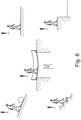
- figure 1 1 shows a schematic representation of a prosthetic device 10 in the form of a prosthetic knee joint with a thigh shaft 11 that is attached to a patient.
- the femoral socket 11 can be fixed to a thigh stump via different mechanisms, for example via suction socket technology, clamping, osseointegrated fixing or in other ways.
- a joint device 20 in the form of a prosthetic knee joint is arranged at the distal end of the thigh shaft 11 and has a proximal component 21 with connection means for attachment to the thigh shaft 11 .
- a distal component 22 in the form of a part of the lower leg is mounted pivotably about a pivot axis 25 on the proximal component 21 .
- the pivot axis 25 is designed as a knee joint axis; in other applications, for example in a prosthetic ankle joint or prosthetic or orthotic devices on the upper extremity, other joint axes are provided accordingly.
- an orthotic device can also be provided in which, instead of replacing a limb, a limb is supported with a natural joint that is still present.
- a thigh splint is fixed to a thigh and a lower leg splint is fixed to a lower leg, for example by means of buckles, straps or shells.
- the upper leg splint and the lower leg splint are coupled to one another via an orthosis knee joint so that they can be pivoted about an axis.
- the proximal component is a lower leg splint and the distal component is a foot part which is arranged in the area of the natural axis of the ankle joint so that it can pivot via a joint.
- An orthotic device is also understood to mean exoskeletons.
- An actuator 30 is arranged between the proximal component 21 and the distal component 22.
- the actuator 30 is arranged predominantly on the distal component 22 and is integrated in a housing.
- the actuator 30 can be designed as a resistance device, for example as a hydraulic damper, pneumatic damper or magnetorheological damper. It is also possible for the actuator to be designed as a motor drive, for example as an electric motor drive, hydraulic drive or pneumatic drive. Also in the case of an embodiment of an actuator 30 as a drive, it can be connected as a resistance device, for example by operating an electric motor in generator mode.
- An extension arm is arranged on the proximal component 21, which is coupled via a piston rod or a push rod to the resistance device or the drive, i.e. the actual actuator 30, with the actuator 30 being connected to the distal component at the other end of the piston rod or the push rod 22 is connected.
- the proximal component 21 performs a pivoting movement relative to the distal component 22; in the position shown, the articulation device 20 is in a maximally extended, ie stretched, position. From this position, a flexion movement occurs which pivots the posterior or posterior side of the proximal component 21 toward the posterior side of the distal component 22 such that the angle on the posterior side between the two components 21, 22 decreases upon flexion and enlarged during extension, i.e. during a stretching movement. As the flexion angle increases, the knee angle decreases.
- the actuator 30 is designed to be adjustable in order to influence the movement behavior during flexion and/or extension.
- the maximum flexion angle or the minimum knee angle can be set, for example, and an increase in resistance can be provided during an extension movement shortly before reaching the maximum extended position in order to avoid a hard stop in the extension position. It is also possible to design the actuator 30 to support the movement, ie as a drive to initiate or support a flexion movement and/or extension movement.
- the actuator 30 is coupled to a control device 50 which, in the illustrated embodiment of FIG figure 1 is integrated in the distal end area of the prosthesis socket 11 .
- Data processing devices, connections, contact surfaces, interfaces and/or an energy store are arranged in the control device in order to receive incoming sensor data or To process data from a detection device 60 .
- the detection device 60 is designed as a surface electrode arrangement which is fastened to the thigh shaft 11 and the thigh via a strap 12 .
- the surface electrodes 60 detect myoelectric signals during the contraction of the thigh muscles and transmit them via cable or wirelessly to the control device 50.
- At least one sensor 40 is arranged on the distal prosthesis component 22 to collect further data about the existing loads, forces, moments, angular positions To detect accelerations and/or spatial orientations and to transmit them to the control device.
- sensors 40 are not required for carrying out the method, but are advantageous as a supplement.
- the detection device 60 with a plurality of surface electrodes arranged circumferentially around the stump enables the detection of muscle contractions via myoelectric signals.
- the surface electrodes can also be integrated in the prosthesis shaft 11.
- the detection device 60 and the surface electrodes on it are arranged and designed in such a way that the activity of different muscle groups can be detected. This makes it possible to record muscles that are responsible for or involved in opposing movements, for example the quadriceps for extension and the hamstrings for flexion, and to record muscle co-contractions, i.e. simultaneous tension of muscle groups. Muscle co-contractions do not only occur in antagonistic muscles or muscle groups. Co-contractions can also occur and be detected when independent muscle groups are contracted, such as the abdominal muscles together with the hip flexors or hamstrings.
- a variant of the prosthetic device is in the figure 2 shown, in which, in addition to a sensor 40 for detecting status information such as forces, moments, angular positions in space or accelerations, a further sensor device 40 is arranged on the femoral shaft 11 .
- This sensor device 40 is also coupled to the control device 50, which is integrated in the thigh shaft 11 in the exemplary embodiment shown.
- the control device 50 has an integrated energy storage unit, for example an accumulator or a battery.
- the detection device 60 is designed as a multiplicity, that is to say at least two, implantable electrodes which are implanted at different points in the musculature of the thigh.
- Muscle activities are recorded via these implanted electrodes 60, either by recording an electrical potential or by recording pressures, temperatures, flow rates, influencing the optical behavior of components or the like.
- the data recorded by the implant can be recorded via a coil arrangement 61, which is arranged on the femoral shaft 11 or is integrated therein, and transmitted to the control device 50.
- the detection device 60 it is also possible for the detection device 60 to be designed as a combination of implanted elements and a coil 61 or a plurality of coils 61 in order to detect muscle contractions and in particular muscle co-contractions through inductive effects occurring during muscle contractions.
- An interface 51 to the joint device 20 is arranged at the distal end of the prosthesis socket 11, via which it is possible to transmit the sensor data regarding the muscle co-contractions and, if applicable, the sensor data from the sensor 40 on the thigh socket 11 to the actuator 30.
- the sensor data of the sensor 40 on the distal prosthesis component 22 are also transmitted to the control device 50 via the interface 51 .
- the actuator 30 is then controlled and influenced, for example by adjusting valves, throttle cross sections, by activating an electromagnet for influencing magneto-rheological fluids, by braking a motor and/or by activating a drive.
- figure 3 shows a further variant of the invention with a basic structure that the Figures 1 and 2 is equivalent to.
- the thigh shaft 11 is removed from the proximal component 21, and the thigh shaft 11 can be mechanically connected to the joint device 20 via the pyramid adapter shown.
- the detection device 60 is again designed as an implantable electrode arrangement with a coil 61 .
- surface electrodes to be arranged in recesses within the prosthesis socket 11 at predefined locations and to be secured via the belt 12 or to be fixed on the inside of the prosthesis socket 11 .
- the electrodes are held in position by the belt 12, which can be in the form of an elastic band, and are pressed onto the skin surface with sufficient contact pressure.
- the thigh shaft 11 itself is electrically conductively connected to the prosthetic joint 20 in order to transmit the data from the detection device 60 to the joint device 20 and in particular to the actuator 30 .
- the implanted electrodes 60 may be inductively powered via the coil 61 on or in the femoral shaft 11 and are positioned to be within the field of the coil 61 during use.
- the data is also transmitted via the coil 61.
- the detection device 60 is first connected to a pre-processing unit 70 to which the raw data from the electrodes 60 are transmitted.
- this can also be done using surface electrodes according to FIG figure 1 take place.
- the raw data are processed in the pre-processing unit 70, for example in a data processing device or in a microcomputer, which is arranged in the pre-processing unit 70 with its own energy supply.
- the data is processed in a microcontroller, which can be arranged directly on the thigh shaft 11, for example integrated in the distal connection piece of the thigh shaft 11, in order to forward only the relevant or meaningful information.
- the processed data are transmitted from the pre-processing unit 70 to the prosthetic knee joint 20, for example via the data connection by means of the electrical coupling of the thigh shaft 11 to the proximal prosthesis component 21.
- the processed and processed raw data from the detection device 60 are transmitted to the control device 50, via which the impedance or the resistance or the drive of the actuator 30 is then controlled.
- Sensor data from the sensors 40 of the thigh and/or the lower part can also be transmitted to the control device 50 .
- the pre-processing unit 70 can be designed together with the detection device 60 as a module that can be attached to an already existing prosthetic socket 11 can be arranged.
- the electrodes 60 are adapted to the coil 61 and the pre-processing unit 70, for example, and have a modular structure.
- the detection device 60, 61 and/or the pre-processing unit 70 can be designed such that it can be switched off, so that the prosthetic device 20 can also function without the control device 50 on the basis of the detected muscle co-contractions.
- the detection device and/or the pre-processing unit 70 are preferably designed to be plug-and-play capable, so that a complex coordination process between the individual components is no longer necessary.
- the muscle activation is measured and recorded via the detection device 60, such as the surface electrodes or implanted electrodes.
- a computing unit either in the pre-processing unit 70 or in the control device 50, it is determined whether a muscle co-contraction is present. The intensity and duration of the respective muscle contractions are determined.
- a control algorithm is used to determine whether and how the actuator 30 is activated or deactivated, i.e. whether there is a change in resistance or a movement is supported should.
- the contraction signals are assigned when the control is set up and adapted to the user. Depending on the position of the respective detection device 60, it can be defined which muscle or which muscle group causes the corresponding contraction signal.
- a pre-processing unit 70 is assigned to or upstream of the control device 50 or the actuator 30, the processed data, for example the cocontraction intensity and the duration of the muscle contractions, are transmitted to the joint device 20, so that the joint device 20 has a signal that is easy to process , which can be easily integrated into the control process. This reduces the control effort and the service life of the The prosthesis device or orthosis device is lengthened, since the signal processing does not result in any negative influence on the running time of the joint device 20 when it is used and possibly retrofitted with the detection device 60 .
- the pre-processing unit 70 can be retrofitted and has its own power supply, the service life of the prosthetic joint 20 is not adversely affected. If necessary, the total service life of the orthotic or prosthetic device 10 can be extended simply by replacing the pre-processing unit 70 with its own energy supply.
- FIG 4 shows a schematic representation of the course of a movement resistance R and a flexion angle ⁇ over time as a function of the detected muscle contraction signals. Shown is a gait cycle beginning with the heel strike or heel strike and ending with the end of the swing phase just before heel strike.
- the flexion angle ⁇ increases, which means that the knee angle decreases.
- a stance phase flexion takes place in order to avoid transmission of force through a stretched leg, for example a stretched prosthesis or orthosis, after the heel has been put on. This dampens the impact movement and allows the artificial knee joint to bend slightly.
- the flexion resistance R is increased in the swing phase in order not to carry out the flexion too far, so that the knee joint can be stretched at the end of the swing phase. Shortly before the movement reversal is reached, the flexion resistance R is not increased any further, and after the maximum flexion angle is reduced to the level needed to dampen the movement in stance phase flexion.
- An increased flexion damping level at the end of the swing phase contributes to the safety of the user, in order to prevent the knee joint from bending in the event of a stumble.
- the flexion resistance R is changed, increased in the illustrated embodiment, which is shown by the dashed line.
- a co-contraction can occur involuntarily, for example, when an obstacle is felt or seen, or when a smooth surface is recognized.
- Increased resistance to flexing of the knee joint is then already provided when the foot or the prosthetic foot is put on, as a result of which the maximum achievable flexion angle ⁇ is reduced, which is also shown by the dashed line.
- the movement is influenced by a greater and earlier increase in the flexion damping in the stance phase flexion phase. This reduces the range of motion, i.e.
- the maximum flexion angle ⁇ and the knee joint feels more compact and stiff.
- the resistance R can also be increased earlier and more, so that the flexion angle increases less quickly and the maximum swing phase flexion is also reduced.
- the knee joint swings up less and thus reaches full extension much earlier and faster. This provides increased security for the user.
- FIG. 5 A variant of the control method for going downhill is in figure 5 shown.
- the standard course of the flexion damping R is shown with the solid line
- the knee angle course ⁇ without control via co-contractions is also shown with the solid line.
- the flexion damping R is increased with bending in the stance phase until the flexion is blocked.
- a so-called plateau phase then sets in, from which the flexion damping R is reduced to a high level in the middle stance phase in order to allow further bending, but with a flatter increase in the flexion angle in order to compensate for the heel detachment and relief of the prosthesis allow a residual swing phase and move onto the next heel to prepare for a strike.
- these resistances can correspondingly be raised earlier or maintained at a higher level longer, such that the knee joint flexes later or more slowly and provides an overall higher level of cushioning against flexion.
- FIG. 6 Situation examples for voluntary or involuntary co-contractions are shown in FIG. 6, for example when an obstacle occurs, when a danger from animals, people or machines is recognized, on slippery surfaces, in suddenly occurring dangerous situations or in the area of unsafe or dangerous environmental conditions.
- the reflexive muscle co-contraction or also the conscious muscle co-contraction enable a control process to be influenced by muscle activation, with a basic pattern of the control process preferably being retained, only the manifestations of strength and duration being changed or influenced.
- influencing the movement behavior via muscle co-contractions has the advantage that this can take place both consciously and unconsciously, as a result of which the reflexes of the human being when perceiving the environment can advantageously be used to control the orthotic or prosthetic device.
- FIG 7 is a schematic representation of the course of a resistance R plotted against time. For example, if a co-contraction is detected that makes it necessary to increase the resistance to flexion, this resistance R is increased very quickly, starting from a base resistance. After a maximum resistance has been reached, for example after the co-contraction has subsided or if a circumstance is detected that causes the controller to reduce the resistance again, the resistance R is first slowly reduced, so that the resistance falls gently over the time. This prevents a rapid drop in resistance from causing a loss of balance and unsafe situations for the user.
Description
Die Erfindung betrifft ein Verfahren zur Steuerung einer orthetischen oder prothetischen Einrichtung wie in den Ansprüchen definiert. Die Erfindung betrifft ebenso eine solche orthetische oder prothetische Einrichtung wie in den Ansprüchen definiert.The invention relates to a method for controlling an orthotic or prosthetic device as defined in the claims. The invention also relates to such an orthotic or prosthetic device as defined in the claims.
Prothetische Einrichtungen oder Orthesen haben die Aufgabe, die Bewegung einer vorhandenen Gliedmaße zu führen oder zu unterstützen, bzw. eine Gliedmaße abzustützen und zu unterstützen. Exoskelette sind ebenfalls orthetische Einrichtungen. Orthetische Einrichtungen für die untere Extremität sind in unterschiedlichen Ausführungsformen bekannt, sogenannte KAFO (knee ankle foot orthosis) stützen sowohl den Fuß als auch das Knöchelgelenk und das Kniegelenk ab. Der Fuß wird in der Regel auf einer Fußplatte aufgesetzt, eine oder mehrere Unterschenkelschienen erstrecken sich parallel zu dem Unterschenkel und ein Orthesenkniegelenk ist ungefähr im Bereich der natürlichen Knieachse vorgesehen. An einer oder mehreren Oberschenkelschienen sind Befestigungseinrichtungen zum Festlegen der Orthese an dem Oberschenkel angebracht. Ebenso können Befestigungseinrichtungen an dem Unterschenkel oder der Fußplatte vorgesehen sein, um die Orthese an dem jeweils zu versorgenden Bein festlegen zu können. Bezüglich des Orthesenkniegelenkes ist die Oberschenkelschiene eine proximale Komponente und die Unterschenkelschiene eine distale Komponente, bezüglich eines Orthesenknöchelgelenkes ist das Fußteil die distale Komponente und die Unterschenkelschiene oder die Unterschenkelschienen die proximale Komponente. Zwischen den jeweiligen Komponenten können Dämpfer oder Antriebe als Aktuatoren angeordnet sein, um Bewegungsabläufe zu beeinflussen und Bewegungswiderstände zu verändern. Es kann entweder ein erhöhter Bewegungswiderstand zum Dämpfen einer Bewegung oder ein verringerter Bewegungswiderstand durch Verringerung einer Dämpfung oder Unterstützung mittels eines oder mehrerer motorischer oder kraftspeichergetriebener Antriebe bereitgestellt werden. Entsprechendes gilt auch für orthetische Einrichtungen wie Orthesen und Exoskelette für die obere Extremität.The task of prosthetic devices or orthoses is to guide or support the movement of an existing limb, or to support and support a limb. Exoskeletons are also orthotic devices. Orthotic devices for the lower extremities are known in different embodiments, so-called KAFO (knee ankle foot orthosis) support both the foot and the ankle joint and the knee joint. The foot is usually placed on a footplate, one or more lower leg splints extend parallel to the lower leg and an orthotic knee joint is provided approximately in the area of the natural knee axis. Fastening devices for fixing the orthosis on the thigh are attached to one or more thigh splints. Fastening devices can also be provided on the lower leg or the foot plate in order to be able to fix the orthosis on the leg to be treated. With regard to the orthotic knee joint, the thigh splint is a proximal component and the lower leg splint is a distal component; with regard to an orthotic ankle joint, the foot part is the distal component and the lower leg splint or splints is the proximal component. Dampers or drives can be arranged as actuators between the respective components in order to sequence movements influence and change resistance to movement. Either an increased resistance to movement for dampening a movement or a reduced resistance to movement by reducing damping or support can be provided by means of one or more motorized or stored-energy drives. The same applies to orthotic devices such as orthoses and exoskeletons for the upper extremity.
Prothesen ersetzen eine nicht vorhandene Gliedmaße und können ein künstliches Gelenk aufweisen. Prothesen der unteren Extremität können beispielsweise ein Prothesenkniegelenk aufweisen, das über ein Unterschenkelrohr als Unterschenkelteil mit einem Prothesenfuß als Fußteil verbunden ist. Zwischen dem Prothesenfuß und dem Unterschenkelrohr kann ein Prothesenknöchelgelenk ausgebildet sein. Das Prothesenkniegelenk weist in der Regel ein Oberteil und ein Unterteil auf, die entweder über eine monozentrische oder polyzentrische Gelenkeinrichtung schwenkbar aneinander gelagert sind, so dass das Oberteil relativ zu dem Unterteil um eine Schwenkachse verschwenkbar ist. An dem Oberteil ist zumindest eine Befestigungseinrichtung angeordnet, um die Prothese der unteren Extremität an einem Anwender festlegen zu können, beispielsweise für einen Oberschenkelschaft oder in Gestalt eines Oberschenkelschaftes. Bezüglich des Prothesenknöchelgelenkes ist das Unterschenkelrohr das Oberteil und der Prothesenfuß das Unterteil. Zwischen dem jeweiligen Oberteil und dem Unterteil oder der proximalen Komponente und der distalen Komponente kann jeweils ein Aktuator angeordnet sein, um den jeweiligen Bewegungswiderstand hinsichtlich einer Flexion und/oder Extension zu verändern. Wie im Zusammenhang mit einer Orthese ausgeführt, kann der Bewegungswiderstand über den Aktuator vergrößert oder verringert werden, beispielsweise über passive, verstellbare Dämpfer oder Antriebe wie Elektromotoren oder kraftspeichergetriebene Antriebe. Neben Prothesen für untere Extremitäten sind entsprechende Prothesen auch für die oberen Extremitäten bekannt. Die oben beschriebenen Merkmale einer Orthese, Prothesen oder Exoskelettes können auch an die erfindungsgemäßen orthetischen und prothetischen Einrichtungen vorhanden sein.Prostheses replace a missing limb and may include an artificial joint. Prostheses of the lower extremity can have a prosthetic knee joint, for example, which is connected to a prosthetic foot as a foot part via a lower leg tube as the lower leg part. A prosthetic ankle joint can be formed between the prosthetic foot and the lower leg tube. The prosthetic knee joint generally has an upper part and a lower part, which are mounted pivotably on one another either via a monocentric or polycentric joint device, so that the upper part can be pivoted about a pivot axis relative to the lower part. At least one fastening device is arranged on the upper part in order to be able to fix the prosthesis of the lower extremity on a user, for example for a femoral socket or in the form of a femoral socket. With regard to the prosthetic ankle joint, the lower leg tube is the upper part and the prosthetic foot is the lower part. An actuator can be arranged between the respective upper part and the lower part or the proximal component and the distal component in order to change the respective movement resistance with regard to flexion and/or extension. As explained in connection with an orthosis, the movement resistance can be increased or reduced via the actuator, for example via passive, adjustable dampers or drives such as electric motors or drives driven by energy storage. In addition to prostheses for the lower extremities, corresponding prostheses are also known for the upper extremities. The features of an orthosis, prostheses or exoskeletons described above can also be present on the orthotic and prosthetic devices according to the invention.
Aus der
Aus der
Darüber hinaus ist aus dem Stand der Technik bekannt, über Elektroden Muskelkontraktionen eines Anwenders zu erfassen, beispielsweise über Oberflächenelektroden oder über implantierte Elektroden, um auf der Grundlage von erfassten Muskelkontraktionen Steuerungsbefehle zu generieren, z.B. um Antriebe zu aktivieren oder zu deaktivieren. Solche auf myoelektrischen Signalen basierende Steuerungen werden insbesondere bei Prothesen der oberen Extremität eingesetzt, um komplexe Bewegungen der Prothesenhand zu steuern.In addition, it is known from the prior art to use electrodes to detect a user's muscle contractions, for example surface electrodes or implanted electrodes, in order to generate control commands based on the detected muscle contractions, e.g. to activate or deactivate drives. Such controls based on myoelectric signals are used in particular in prostheses of the upper extremity in order to control complex movements of the prosthetic hand.
Orthetische oder prothetische Einrichtungen der unteren Extremität werden überwiegend über die Bewegungen und Belastungen des Körpers bzw. der orthetischen oder prothetischen Einrichtung beeinflusst, die auftretenden Beschleunigungen oder Kräfte oder Zustände werden von Sensoren erfasst und den Sensorsignalen basierend wird ein bestimmtes Dämpfungsverhalten eingestellt. Eine willentliche Beeinflussung ist nur über eine Veränderung der Bewegungen oder Systembelastungen möglich. Bei aktiven, angetriebenen orthetischen oder prothetischen Einrichtungen ist es bekannt, über eine proportionale Zuordnung von Muskelaktivität zum Antrieb eine Verlagerung von Komponenten zueinander zu bewirken, beispielsweise eine Hand zu öffnen oder zu schließen oder über eine Mustererkennung bestimmte Programme anzusteuern. Kontraktionssignale werden erfasst, um zwischen verschiedenen Betriebsmodi hin- und herzuschalten.Orthotic or prosthetic devices of the lower extremities are mainly influenced by the movements and loads of the body or the orthotic or prosthetic device, the accelerations or forces or states that occur are detected by sensors and a specific damping behavior is set based on the sensor signals. A willful influence is only possible by changing the movements or system loads. In the case of active, powered orthotic or prosthetic devices, it is known to shift components relative to one another by proportionally allocating muscle activity to the drive, for example opening or closing a hand or controlling specific programs via pattern recognition. Contraction signals are sensed to toggle between different modes of operation.
Die
Die
Aufgabe der vorliegenden Erfindung ist es, für Anwender eine orthetische oder prothetische Einrichtung und ein Verfahren zu deren Steuerung bereitzustellen, die eine erhöhte Sicherheit für den Nutzer bereitstellen, bei einer gleichzeitig einfachen Implementierung mit einem möglichst geringen Kostenaufwand.The object of the present invention is to provide users with an orthotic or prosthetic device and a method for controlling it, which provide increased safety for the user, while at the same time being simple to implement at the lowest possible cost.
Erfindungsgemäß wird diese Aufgabe durch ein Verfahren und eine orthetische oder prothetische Einrichtung mit den Merkmalen der unabhängigen Ansprüche gelöst, vorteilhafte Ausgestaltungen und Weiterbildungen der Erfindung sind in den Unteransprüchen, der Beschreibung sowie den Figuren offenbart.According to the invention, this object is achieved by a method and an orthotic or prosthetic device with the features of the independent claims. Advantageous configurations and developments of the invention are disclosed in the dependent claims, the description and the figures.
Das Verfahren zur Steuerung einer orthetischen oder prothetischen Einrichtung, die an einem Körper eines Anwenders anlegbar und daran festlegbar ist, mit einer Gelenkeinrichtung mit einer proximalen Komponente und einer distalen Komponente, die um eine Schwenkachse schwenkbar aneinander gelagert sind, zumindest einen verstellbaren Aktuator, der zwischen der proximalen Komponente und der distalen Komponente angeordnet ist und über die ein Bewegungswiderstand gegen eine Verschwenkung der proximalen Komponente relativ zu der distalen Komponente einstellbar ist, zumindest einer Erfassungseinrichtung zur Erfassung von Muskelkontraktionen sowie einer Steuerungseinrichtung, die mit der Erfassungseinrichtung und dem Aktuator gekoppelt ist, Signale von der Erfassungseinrichtung verarbeitet und in Abhängigkeit von den Signalen den Aktuator verstellt, sieht vor, dass die Erfassungseinrichtung zur Erfassung von Muskelkokontraktionen eingerichtet ist und an einer Gliedmaße des Anwenders angeordnet und mit der Steuerungseinrichtung gekoppelt wird, dass zumindest eine Muskelkokontraktion von der Erfassungseinrichtung detektiert wird, dass ermittelt wird, ob eine Kokontraktion vorliegt und dass der Bewegungswiderstand des Aktuators in Abhängigkeit von der detektierten Muskelkokontraktion verändert wird. Eine Muskelkokontraktion ist das Anspannen von Agonisten und Antagonisten zur Gelenkstabilisierung oder das gleichzeitige Anspannen zweier entgegengesetzt wirkender Muskeln oder Muskelgruppen. Eine Muskelkokontraktion liegt beispielsweise vor, wenn der Armbizeps und der Trizeps gleichzeitig angespannt werden, ohne dass sich der Unterarm relativ zu dem Oberarm bewegt oder aber je nach Kontraktionsniveau langsamer als ohne Anspannung des Antagonisten bewegt. Entsprechendes gilt für die den Unterschenkel streckende und beugende Muskulatur. Werden einander entgegengesetzt wirkende Muskeln oder Muskelgruppen gleichzeitig angespannt, spricht man von Muskelkokontraktionen. Muskelkokontraktionen werden dazu eingesetzt, um Gelenke oder Gliedmaße zu stabilisieren, um bei einer Ausführung von Bewegungen ein Höchstmaß von Kontrolle zu haben oder um Bewegungen abzustoppen. Muskelkokontraktionen erfolgen bewusst oder unbewusst. Eine unbewusste Kokontraktion tritt beispielsweise als Reflex bei plötzlichen Störungen, wie auftretender Glätte, rutschigem Boden, Schrecksituationen wie Explosionen, Unfällen oder ähnlichem oder aber auch zur Vorbereitung auf möglicherweise gefährliche Situationen auf, wie das Entlanggehen an einem Abgrund oder über eine Brücke. Über eine Muskelkokontraktion wird die Grundspannung in dem muskulären System erhöht. Wird über die Erfassungseinrichtung eine entsprechende Muskelkokontraktion erfasst oder detektiert, werden also beispielsweise das gleichzeitige Anspannen von Armbizeps und Armtrizeps oder beispielsweise des musculus biceps femoris und des musculus quadriceps femoris von der Erfassungseinrichtung erfasst, werden von der Erfassungseinrichtung entsprechende Signale an die Steuerungseinrichtung übermittelt, die dann in Abhängigkeit von den detektieren Muskelkokontraktionen den Bewegungswiderstand des Aktuators verändert. Die Veränderung des Bewegungswiderstandes kann beispielsweise durch das Verstellen von Ventilen in einem Hydraulikdämpfer oder einem Pneumatikdämpfer erfolgen. Ebenso können Bremsen gelöst oder aktiviert werden oder andere Widerstände vergrößert oder verringert werden, beispielsweise über elektrische Antriebe die zugeschaltet oder gesperrt oder in einer Verlagerung der proximalen Komponente relativ zu der distalen Komponente entgegenwirkt. Bevorzugt bleibt die Grundeinstellung des Aktuators unverändert, das heißt, dass die einmal eingestellte Widerstandskurve oder ein Widerstandsverlauf über eine bestimmte Bewegung oder eine bestimmte Belastung beibehalten wird, also dass grundsätzliche Widerstandsverhalten über die Bewegung unverändert bleibt. Bei ausgewählten Muskeln, insbesondere bei Muskeln, die für die Ausführung der jeweiligen Bewegung zuständig sind oder zuständig wären, wenn die Gliedmaße noch vorhanden wäre, wird die Muskelaktivität über die Erfassungseinrichtung erfasst. Wird dann eine willkürliche oder unwillkürliche Muskelkokontraktion detektiert, wird auf eine Sondersituation geschlossen, die eine Veränderung des Bewegungswiderstandes erforderlich macht. Anders als bei Prothesensteuerungen der oberen Extremität werden Muskelkokontraktionen nicht zum Umschalten und zum Einschalten eines neuen Betriebsmodus eingestellt, beispielsweise um von dem Betriebsmodus des Handöffnens auf den Betriebsmodus des Handschließens umzuschalten, vielmehr werden die gleichen Bewegungen weiterhin zugelassen, jedoch auf einem anderen Widerstandsniveau oder der Widerstand wird soweit erhöht, dass eine Weiterbewegung des Gelenkes bei üblichen Belastungsszenarien nicht mehr möglich ist. Es handelt sich somit um eine Variation eines originären Steuerungsverhaltens, basierend auf der erfassten Kokontraktion.The method for controlling an orthotic or prosthetic device that can be placed on a user's body and fixed thereto, having a joint device with a proximal component and a distal component that are pivotably mounted on one another about a pivot axis, at least one adjustable actuator that is connected between between the proximal component and the distal component and via which a resistance to movement against pivoting of the proximal component relative to the distal component can be adjusted, at least one detection device for detecting muscle contractions and a control device, which is coupled to the detection device and the actuator, signals processed by the detection device and the actuator adjusted depending on the signals, provides that the detection device is set up to detect muscle co-contractions and at a The user's limb is arranged and coupled to the control device, that at least one muscle co-contraction is detected by the detection device, that it is determined whether a co-contraction is present and that the movement resistance of the actuator is changed depending on the detected muscle co-contraction. Muscle co-contraction is the tensing of agonists and antagonists to stabilize the joint, or the simultaneous tensing of two opposing muscles or muscle groups. A muscle co-contraction occurs, for example, when the arm biceps and triceps are contracted simultaneously without the forearm moving relative to the upper arm or, depending on the level of contraction, moving more slowly than without the antagonist contracting. The same applies to the muscles that stretch and bend the lower leg. If opposing muscles or muscle groups are contracted at the same time, this is called muscle co-contraction. Muscle co-contractions are used to stabilize joints or limbs, to have maximum control when performing movements, or to stop movements. Muscle co-contractions occur consciously or unconsciously. An unconscious co-contraction occurs, for example, as a reflex in the event of sudden disturbances, such as slippery surfaces, slippery ground, frightening situations such as explosions, accidents or the like, or in preparation for potentially dangerous situations, such as walking along an abyss or over a bridge. The basic tension in the muscular system is increased via a muscle co-contraction. If the detection device detects a corresponding muscle co-contraction, for example if the arm biceps and arm triceps or the musculus biceps femoris and the musculus quadriceps femoris are simultaneously contracted by the detection device, corresponding signals are transmitted by the detection device to the control device, which then changes the movement resistance of the actuator depending on the detected muscle co-contractions. The movement resistance can be changed, for example, by adjusting valves in a hydraulic damper or a pneumatic damper. Likewise, brakes can be released or activated or other resistances can be increased or reduced, for example via electric drives that are switched on or off or by shifting the proximal component relative to the distal one component counteracts. The basic setting of the actuator preferably remains unchanged, which means that once the resistance curve or a resistance course has been set, it is maintained over a specific movement or a specific load, ie the basic resistance behavior remains unchanged over the movement. In the case of selected muscles, in particular muscles that are responsible for executing the respective movement or would be responsible if the limb were still present, the muscle activity is detected via the detection device. If a voluntary or involuntary muscle co-contraction is then detected, a special situation is concluded that requires a change in the movement resistance. Unlike upper extremity prosthesis controls, muscle co-contractions are not set to toggle and engage a new mode of operation, for example to switch from hand open mode to hand close mode of operation, rather the same movements are still allowed but at a different resistance level or resistance is increased to such an extent that further movement of the joint is no longer possible under normal load scenarios. It is therefore a variation of an original control behavior based on the detected co-contraction.
In einer Ausführungsform der Erfindung werden die Dauer und/oder die Intensität der Muskelkokontraktion oder der Muskelkokontraktionen erfasst und in Abhängigkeit von der Dauer und/oder der Intensität der Muskelkokontraktion oder Muskelkokontraktionen wird der Bewegungswiderstand verändert. Beispielsweise wird bei einer länger andauernden Muskelkokontraktion der Bewegungswiderstand über einen längeren Zeitraum verändert. Ebenso kann bei einer hohen Muskelkokontraktionsintensität eine Vergrößerung der Veränderungsamplitude verglichen mit einer geringeren Muskelkokontraktionsintensität ausgeführt werden, um den Bewegungswiderstand angepasst zu verändern. Beispielsweise kann der Bewegungswiderstand bei der Detektion einer Muskelkokontraktion vergrößert werden, was dem Effekt der Muskelkokontraktion bei einer gesunden Gliedmaße entspricht. Bemerkt beispielsweise der Nutzer der orthetischen oder prothetischen Einrichtung vor sich eine Veränderung der Beschaffenheit des Untergrundes, beispielsweise eine feuchte Stelle auf einem glatten Boden, wird durch die Muskelkokontraktion der Bewegungswiderstand beispielsweise in einem Prothesenkniegelenk oder Orthesenkniegelenk vergrößert, wodurch der Anwender ein erhöhtes Sicherheitsgefühl erhält, da die Gelenkeinrichtung besser von der übrigen Muskulatur kontrolliert und orientiert werden kann. Bei einer Prothese erfolgt die Kontrolle dann über den Oberschenkelstumpf. Bei aktiven orthetischen oder prothetischen Einrichtungen, also Einrichtungen mit motorischen oder anderweitigen Antrieben, können die eine Bewegung unterstützenden Kräfte verringert, Widerstände in den Antrieben vergrößert oder Antriebe gegenläufig aktiviert werden, um ein Verschwenken der distalen und proximalen Komponenten zueinander zu verhindern oder zu behindern.In one embodiment of the invention, the duration and/or the intensity of the muscle co-contraction or muscle co-contractions are recorded and the movement resistance is changed depending on the duration and/or the intensity of the muscle co-contraction or muscle co-contractions. For example, in the case of a prolonged muscle co-contraction, the resistance to movement is changed over a longer period of time. Likewise, with a high muscle co-contraction intensity, an increase in the change amplitude can be carried out compared to a lower muscle co-contraction intensity in order to change the movement resistance appropriately. For example, the resistance to movement can be increased upon detection of a muscle co-contraction, which corresponds to the effect of muscle co-contraction in a healthy limb. If, for example, the user of the orthotic or prosthetic device notices a change in the nature of the subsoil in front of him, for example a damp spot on a slippery floor, the muscle co-contraction increases the movement resistance, for example in a prosthetic knee joint or orthotic knee joint, which gives the user an increased sense of security, since the joint device can be better controlled and oriented by the rest of the muscles. In the case of a prosthesis, the control is then carried out via the thigh stump. In the case of active orthotic or prosthetic devices, ie devices with motorized or other drives, the forces supporting a movement can be reduced, resistances in the drives can be increased or drives can be activated in opposite directions in order to prevent or impede pivoting of the distal and proximal components relative to one another.
Bei zunehmender Muskelkokontraktionsintensität und/oder Muskelkokontraktionsdauer kann der Bewegungswiderstand zunehmend vergrößert werden, so dass durch die Erfassung des zeitlichen Verlaufes der Muskelkokontraktionsintensität und/oder Muskelkokontraktionsdauer eine proportionale Veränderung des Bewegungswiderstandes erfolgen kann. Steigert sich die Intensität über einen Kokontraktionszeitraum, wird die Veränderung vergrößert. Ebenso ist es möglich, dass unabhängig von der Intensität der Kokontraktion der Bewegungswiderstand bei Vorliegen einer Kokontraktion solange vergrößert wird, wie die Kontraktion andauert, also dass bei einer längeren Kokontraktionsdauer eine größere Veränderung als bei einer kurzen Kokontraktionsdauer ausgeführt wird. Alternativ oder ergänzend kann am Ende einer Kokontraktion und/oder bei Detektion einer anderen Kokontraktion und/oder durch einen aktiven Auslöser und/oder einen Sprachbefehl der Widerstand verringert werden. Alle Veränderungsmethoden können alleine oder auch gemeinsam oder in einer beliebigen Kombination angewendet werden.With increasing muscle co-contraction intensity and/or muscle co-contraction duration, the movement resistance can be increasingly increased, so that a proportional change in the movement resistance can take place by recording the temporal progression of the muscle co-contraction intensity and/or muscle co-contraction duration. As the intensity increases over a period of cocontraction, the change is magnified. It is also possible that, regardless of the intensity of the co-contraction, the movement resistance in the presence of a co-contraction is increased as long as the contraction lasts, ie that a greater change is carried out with a longer co-contraction period than with a short co-contraction period. Alternatively or additionally, the resistance can be reduced at the end of a co-contraction and/or upon detection of another co-contraction and/or by an active trigger and/or a voice command. All change methods can be used alone or together or in any combination.
Eine Weiterbildung der Erfindung sieht vor, dass der Widerstand zunächst sehr schnell erhöht wird, also dass ein steiler Anstieg der Widerstandskraft erfolgt, wobei die Verringerung des Widerstandes langsam, zumindest langsamer als der Anstieg erfolgt, also der Abfall der Widerstandskraft weniger steil ausgeführt wird.A further development of the invention provides that the resistance is initially increased very quickly, i.e. there is a steep increase in the resistance force, with the resistance decreasing slowly, at least more slowly than the increase, i.e. the drop in the resistance force being less steep.
Die Veränderung des Bewegungswiderstandes kann einem voreingestellten Steuerungsprogramm überlagert werden. Moderne Orthesen oder Prothesen weisen häufig Aktuatoren auf, die sensorgesteuert verschiedene Bewegungswiderstände bereitstellen, so dass beispielsweise in einem Gangzyklus unterschiedliche Flexions- und Extensionswiderstände in den jeweiligen Gangphasen eingestellt werden. Durch Lagesensoren, Kraftsensoren, Momentensensoren, Winkelsensoren und Beschleunigungssensoren sowie anderer Sensoren ist es möglich, den gegenwärtigen Zustand der Prothese, Orthese oder eines Exoskelettes zu erfassen und ein an den Zustand oder das Bewegungsverhalten angepasstes Widerstandsverhalten bereitzustellen. Dieses Steuerprogramm kann auch bei der Detektion einer Muskelkokontraktion grundsätzlich beibehalten werden, das heißt, dass das bereits bestehende Dämpfungskonzept oder Antriebskonzept basierend auf den entsprechenden Sensoren grundsätzlich unverändert bleiben kann. Lediglich das Widerstandsniveau oder die Dauer unterschiedlicher Widerstände werden für die Dauer der Muskelkokontraktion beeinflusst. Die Verläufe der Widerstände über die Zeit bei dem normalen Steuerungsprogramm können in der Amplitude und/oder über das zeitliche Ausmaß durch die Veränderung des Bewegungswiderstandes durch die detektierte Muskelkokontraktion verändert werden. Dadurch werden insgesamt die Stabilität der jeweiligen Gelenkeinrichtung und damit auch die Stabilität der orthetischen oder prothetischen Einrichtung vergrößert. Bei Wegfall der Muskelkokontraktion wird wieder das voreingestellte Standardprogramm aktiviert.The change in the resistance to movement can be superimposed on a preset control program. Modern orthoses or prostheses often have actuators that provide different movement resistances under sensor control, so that, for example, different flexion and movement forces can be achieved in a gait cycle Extension resistances can be set in the respective gait phases. Position sensors, force sensors, torque sensors, angle sensors and acceleration sensors as well as other sensors make it possible to record the current state of the prosthesis, orthosis or an exoskeleton and to provide a resistance behavior that is adapted to the state or the movement behavior. In principle, this control program can also be retained when a muscle co-contraction is detected, which means that the already existing damping concept or drive concept based on the corresponding sensors can basically remain unchanged. Only the resistance level or the duration of different resistances are influenced for the duration of the muscle co-contraction. The progression of the resistances over time in the normal control program can be changed in terms of amplitude and/or the extent over time by changing the movement resistance through the detected muscle co-contraction. This increases the overall stability of the respective joint device and thus also the stability of the orthotic or prosthetic device. If the muscle co-contraction ceases, the preset standard program is activated again.
Grundsätzlich ist es auch möglich, dass die Veränderung des Bewegungswiderstandes auch bei Aktuatoren angewendet wird, die nicht über ein anderweitig sensorgesteuertes Steuerungsverfahren verfügen, sondern beispielsweise fest eingestellt an dem jeweiligen Anwender ein bestimmtes Dämpfungsverhalten oder Bewegungswiderstandsverhalten aufweisen.In principle, it is also possible for the change in the movement resistance to also be applied to actuators that do not have a different sensor-controlled control method, but instead have a specific damping behavior or movement resistance behavior that is permanently set for the respective user.
Die Veränderung des Bewegungswiderstandes kann die Größe des Bewegungswiderstandes, also die Amplitude des Bewegungswiderstandes, und/oder die Dauer des Bewegungswiderstandes, also den zeitlichen Verlauf über den Bewegungszyklus, beeinflussen.The change in the resistance to movement can affect the size of the resistance to movement, ie the amplitude of the resistance to movement, and/or the duration of the resistance to movement, ie the course over time over the movement cycle.
Die Muskelkontraktionen und damit auch die Muskelkokontraktionen werden von der Erfassungseinrichtung in einem Ausführungsbeispiel als myoelektrische Signale, Drucksignale, induktiv erzeugte Signale und/oder opto-elektronisch erzeugte Signale erfasst und der Steuerungseinrichtung übermittelt. Die Steuerungseinrichtung ist als eine Datenverarbeitungseinrichtung ausgebildet und weist einen Prozessor oder einen Computer auf, der elektrische Signale verarbeitet. Die Signale werden von Sensoren oder Detektoren erzeugt, die unterschiedliche physikalische, chemische oder biologische Effekte ausnutzen. Die Erfassungseinrichtung kann beispielsweise Oberflächenelektroden zur Erfassung myoelektrischer Signale aufweisen. Myoelektrische Signale entstehen bei der Kontraktion von Muskeln. Der Vorteil von Oberflächenelektroden ist die leichte Handhabbarkeit, das reversible Anlegen, die Anpassbarkeit an den jeweiligen Anwender sowie der non-invasive Charakter. Oberflächenelektroden können jedoch verrutschen und müssen in der Regel präzise angeordnet werden, um eine ausreichende Signalqualität bereitzustellen. Weiterhin ist es möglich, über Implantate in dem Muskel elektrische Potentiale abzugreifen und diese über Schnittstellen oder drahtlos an Empfänger zu übermitteln, die dann die Signale in elektrischer Form an die Steuerungseinrichtung übermittelt. Ebenfalls ist es möglich, Drucksensoren an oder in den jeweiligen Muskeln zu positionieren. Durch die Muskelkontraktionen verändert sich die Form des Muskels, was wiederum zu Veränderungen des Druckes beispielsweise an einer Manschette, Spange oder einem Aufnahmeschaft für einen Stumpf, beispielsweise einem Oberschenkelschaft, führt. Die Sensoren können ebenfalls von außen an dem Muskel oder der Gliedmaße angelegt werden, beispielsweise über einen Gurt oder über ein elastisches Band mit einer Vorspannung versehen sein, um die jeweiligen Druckänderungen zu detektieren. Auch Veränderungen in der optischen Durchlässigkeit können zur Detektion von Muskelkontraktionen ausgenutzt werden. Es besteht die Möglichkeit, Spulen in einem Schaft unterzubringen und implantierte Elektroden in der Muskulatur mikroinvasiv einzupflanzen. Die implantierten Elektroden werden über die Spule oder die Spulen in dem Schaft induktiv mit Energie versorgt und übertragen die jeweils erfassten Daten drahtlos oder drahtgebunden über die Spule oder Spulen an eine Auswerteeinheit, die dann diese Daten der Steuerungseinrichtung übermittelt. Grundsätzlich wird die Muskelaktivierung über Elektroden, Sensoren oder Detektoren ermittelt. In einer Recheneinheit wird aus den elektrischen Signalen die Co-Kontraktion sowie deren Intensität und Dauer ermittelt und auf der Grundlage dieser Informationen wird der Steuerungs-Algorithmus angepasst.The muscle contractions and thus also the muscle co-contractions are detected by the detection device in one embodiment as myoelectric signals, pressure signals, inductively generated signals and/or opto-electronically generated signals and transmitted to the control device. The controller is as formed a data processing device and has a processor or a computer that processes electrical signals. The signals are generated by sensors or detectors that use different physical, chemical or biological effects. The detection device can, for example, have surface electrodes for detecting myoelectric signals. Myoelectric signals are generated when muscles contract. The advantage of surface electrodes is that they are easy to handle, can be applied reversible, can be adapted to the respective user and are non-invasive. However, surface electrodes can slip and usually have to be placed precisely in order to provide sufficient signal quality. Furthermore, it is possible to pick up electrical potentials via implants in the muscle and to transmit these via interfaces or wirelessly to receivers, which then transmit the signals in electrical form to the control device. It is also possible to position pressure sensors on or in the respective muscles. The shape of the muscle changes as a result of the muscle contractions, which in turn leads to changes in the pressure, for example on a cuff, brace or a socket for a stump, for example a thigh socket. The sensors can also be applied to the muscle or the limb from the outside, for example by means of a belt or an elastic band with a pretension, in order to detect the respective pressure changes. Changes in optical transparency can also be used to detect muscle contractions. There is the possibility of accommodating coils in a shaft and implanting electrodes in the muscles micro-invasively. The implanted electrodes are supplied with energy inductively via the coil or coils in the shaft and transmit the data recorded in each case wirelessly or by wire via the coil or coils to an evaluation unit, which then transmits this data to the control device. In principle, muscle activation is determined using electrodes, sensors or detectors. In a computing unit, the co-contraction and its intensity and duration are determined from the electrical signals and the control algorithm is adapted on the basis of this information.
Eine Variante der Erfindung sieht vor, dass die von der Erfassungseinrichtung, beispielsweise Oberflächenelektrodenanordnungen, Implantaten, Drucksensoreinrichtungen, optische Sensoreinrichtungen und/oder induktiv arbeitende Sensoreinrichtungen, detektierten Rohsignale in einer Pre-Processing-Einheit aufbereitet werden und erst die aufbereiteten Signale an die Steuerungseinrichtung übermittelt werden. Das Pre-Processing der Rohsignale von den jeweiligen Sensoren oder Detektoren erfolgt beispielsweise in einem Mikrokontroller oder in einer separaten Recheneinheit, die in der Nähe oder in einem baulichen Zusammenhang zu der Erfassungseinrichtung und den Detektoren steht. Beispielsweise kann die Pre-Processing-Einheit an einer der Komponenten, beispielsweise der proximalen Komponente, angeordnet sein und drahtlos oder über eine drahtgebundene Verbindung mit der Steuerungseinrichtung gekoppelt sein. Die Pre-Processing-Einheit übermittelt in einer Ausführungsform nur noch die für das Steuerungsverfahren relevanten Informationen der Steuerungseinrichtung, beispielsweise die Kokontraktionsintensität und die Kokontraktionsdauer oder nur das Signal, dass eine Kokontraktion vorliegt, um die eigentliche Steuerungseinheit, die gegebenenfalls auch noch andere Steuerungsaufgaben durchzuführen hat, nicht mit der Verarbeitung von Rohsignalen belasten zu müssen. Der Steuerungseinrichtung steht dadurch ein einfach zu verarbeitendes, aufbereitetes Signal zur Verfügung, das einfach in den bereits vorhandenen Steuerungsalgorithmus integriert werden kann. Die Erfassungseinrichtung und die Pre-Processing-Einheit können als Modul aufgebaut und als Zusatzbauteil für bereits vorhandene Steuerungen eingesetzt werden. Das Modul kann einen eigenen Energiespeicher aufweisen. Neben einer hohen Flexibilität durch den modularen Aufbau wird zudem keine negative Beeinflussung der Akkulaufzeit der bereits vorhandenen Steuerungseinrichtung bei einer zusätzlichen Funktionalität erreicht.A variant of the invention provides that the raw signals detected by the detection device, for example surface electrode arrangements, implants, pressure sensor devices, optical sensor devices and/or inductively operating sensor devices, are processed in a pre-processing unit and only the processed signals are transmitted to the control device . The pre-processing of the raw signals from the respective sensors or detectors takes place, for example, in a microcontroller or in a separate computing unit that is close to or structurally related to the detection device and the detectors. For example, the pre-processing unit can be arranged on one of the components, for example the proximal component, and can be coupled to the control device wirelessly or via a wired connection. In one embodiment, the pre-processing unit only transmits the information from the control device that is relevant to the control method, for example the cocontraction intensity and the cocontraction duration or only the signal that a cocontraction is present, to the actual control unit, which may also have to carry out other control tasks , not having to be burdened with the processing of raw signals. As a result, the control device has a processed signal that is easy to process and can be easily integrated into the existing control algorithm. The detection device and the pre-processing unit can be constructed as a module and used as an additional component for existing controls. The module can have its own energy store. In addition to a high level of flexibility due to the modular design, no negative impact on the battery life of the existing control device is achieved with an additional functionality.
Als Kokontraktion werden nicht nur die Anspannung von Agonist und Antagonist, sondern allgemein die gleichzeitige Anspannung mehrerer Muskelgruppen, welche unterschiedliche oder unabhängige Funktionen erfüllen, angesehen. Ist beispielsweise ist einer der Muskeln eine Antagonist/Agonist-Paares nicht mehr vorhanden, kann die Aktivierung eines anderen Muskels oder einer andern Muskelgruppe als Antagonist des verbliebenen Muskels definiert werden. Ist zum Beispiel der Beinstrecker oder musculus quadriceps femoris vorhanden, der Beinbeuger oder musculus biceps femoris jedoch nicht, ist eine originäre Kokontraktion nicht möglich, so dass statt dessen die Kontraktion der Abduktoren und/oder der Bauchmuskulatur hinzugenommen werden kann, um eine Kokontraktionssignal für die Steuerung zu erhalten.Not only the contraction of agonist and antagonist, but generally the simultaneous contraction of several muscle groups that fulfill different or independent functions are regarded as co-contraction. For example, if one of the muscles in an antagonist/agonist pair is no longer present, activation of another muscle or muscle group can be defined as an antagonist of the remaining muscle. For example, if the leg extensor or musculus quadriceps femoris is present, but the hamstrings or musculus biceps femoris are not, an original co-contraction is not possible, so that instead, the contraction of the abductors and/or the abdominal muscles can be added to obtain a co-contraction signal for the controller.
Die orthetische oder prothetische Einrichtung, die an einem Körper eines Anwenders anlegbar und daran festlegbar ist, mit einer Gelenkeinrichtung mit einer proximalen Komponente und einer distalen Komponente, die um eine Schwenkachse schwenkbar ineinander gelagert sind, zumindest einem verstellbaren Aktuator, der zwischen der proximalen Komponente und der distalen Komponente angeordnet ist und über die ein Bewegungswiderstand gegen eine Verschwenkung der proximalen Komponente relativ zu der distalen Komponente einstellbar ist, zumindest eine Erfassungseinrichtung zur Erfassung von Muskelkontraktionen sowie einer Steuerungseinrichtung, die mit der Erfassungseinrichtung und dem Aktuator gekoppelt ist, Signale von der Erfassungseinrichtung verarbeitet und in Abhängigkeit von den Signalen den Aktuator verstellt, sieht vor, dass die Erfassungseinrichtung zur Erfassung des Vorliegens von willkürlichen oder unwillkürlichen Muskelkokontraktionen und die Steuerungseinrichtung zur Durchführung des Verfahrens, wie es oben beschrieben ist, eingerichtet ist. Mit einer solchen orthetischen oder prothetischen Einrichtung, beispielsweise einer Orthese, einem Exoskelett oder einer Prothese, ist es möglich, willkürlich oder unwillkürlich das Widerstandsniveau des verstellbaren Aktuator situationsangepasst zu verändern und eine Überlagerung eines bereits vorhandenen Steuerungsprogrammes zu ermöglichen, um für einen Anwender auf einfache Art und Weise und intuitiv eine Anpassung an ein gesteigertes Sicherheitsbedürfnis zu erreichen. Das Gelenk wird steifer, da eine Relativverschwenkung von proximaler und distaler Komponente erschwert oder unterbunden wird, so dass der Nutzer eine bessere Kontrolle über die Einrichtung bekommt.The orthotic or prosthetic device that can be placed on a user's body and fixed thereto, with a joint device with a proximal component and a distal component, which are pivotably mounted one inside the other about a pivot axis, at least one adjustable actuator, which is positioned between the proximal component and of the distal component and via which a resistance to movement against pivoting of the proximal component relative to the distal component can be adjusted, at least one detection device for detecting muscle contractions and a control device, which is coupled to the detection device and the actuator, processes signals from the detection device and adjusts the actuator as a function of the signals, provides that the detection device is set up to detect the presence of voluntary or involuntary muscle co-contractions and the control device is set up to carry out the method as described above. With such an orthotic or prosthetic device, for example an orthosis, an exoskeleton or a prosthesis, it is possible to voluntarily or involuntarily change the resistance level of the adjustable actuator to suit the situation and to allow an existing control program to be overlaid in order to make this easy for a user and to adapt to an increased need for security in a way and intuitively. The joint becomes stiffer because relative pivoting of the proximal and distal components is made more difficult or prevented, so that the user has better control over the device.
Die Erfassungseinrichtung kann als Oberflächenelektrodenanordnung, als Implantat, als Drucksensoreinrichtung, als optische Sensoreinrichtung und/oder als inaktiv arbeitende Sensoreinrichtung ausgebildet sein. Die Anordnung der Erfassungseinrichtung ist dabei so ausgebildet, dass Muskelkokontraktionen erfasst werden können. Dazu sind die jeweiligen Sensoren oder Detektoren an den entsprechenden Muskeln angeordnet oder mit ihnen gekoppelt, beispielsweise über Implantate entsprechend präpariert, sodass Muskelkontraktionen erfasst, Kokontraktionen festgestellt und entsprechende Veränderungen in dem Aktuator ausgeführt werden können.The detection device can be designed as a surface electrode arrangement, as an implant, as a pressure sensor device, as an optical sensor device and/or as an inactively working sensor device. The arrangement of the detection device is designed in such a way that muscle co-contractions can be detected. For this purpose, the respective sensors or detectors are arranged on the corresponding muscles or coupled to them, for example prepared accordingly via implants, so that muscle contractions can be detected, co-contractions determined and corresponding changes in the actuator can be carried out.
Die Erfassungseinrichtung kann in einer Ausführungsform in der proximalen und/oder distalen Komponente integriert sein. Bei Prothesen ist beispielsweise ein Aufnahmeschaft für einen Stumpfteil der proximalen Komponente. Sensoren können fest installiert in dem Aufnahmeschaft und/oder in einem Prothesenliner angeordnet sein. Ebenso können Ausnehmungen oder Durchbrüche zur Positionierung von Elektroden oder anderen Sensoren in dem Schaft oder einer anderen Aufnahmeeinrichtung für ein Körperteil ausgebildet sein, sodass unterschiedliche Sensoren oder Sensoren auswechselbar und anpassbar an den jeweiligen Anwender an der proximalen Komponente befestigt werden können. Oberflächenelektroden könnten auf der Innenseite eines Schaftes einlaminiert oder dauerhaft befestigt sein. Eine separate Steuerungseinrichtung oder eine Pre-Processing-Einheit kann ebenfalls in dem Schaft oder in der proximalen Komponente integriert oder daran befestigt sein, gegebenenfalls mit einer eigenen Energieversorgung, um die Sensordaten hinsichtlich der jeweiligen Muskelkontraktionen aufzuarbeiten, auszuwerten und die aufbereiteten Daten der Steuerungseinrichtung zu übermitteln, die dann den Aktuator entsprechend mit Steuerungssignalen zur Veränderung des Bewegungswiderstandes versorgt.In one embodiment, the detection device can be integrated in the proximal and/or distal component. In the case of prostheses, for example, a receiving socket for a stump part is the proximal component. Sensors can be permanently installed in the socket and/or arranged in a prosthesis liner. Recesses or openings for positioning electrodes or other sensors can also be formed in the shaft or another receiving device for a body part, so that different sensors or sensors can be attached to the proximal component so that they can be exchanged and adapted to the respective user. Surface electrodes could be laminated or permanently attached to the inside of a shaft. A separate control device or a pre-processing unit can also be integrated into the shaft or in the proximal component or attached thereto, possibly with its own power supply, in order to process and evaluate the sensor data with regard to the respective muscle contractions and to transmit the processed data to the control device , which then supplies the actuator with control signals to change the movement resistance accordingly.
In einer Ausführungsform der Erfindung ist an der orthetischen oder prothetischen Einrichtung zumindest ein Sensor zur Erfassung von Kräften, Winkeln, Positionen, Beschleunigungen und/oder Momenten angeordnet und mit der Steuerungseinrichtung gekoppelt. Der jeweilige Sensor kann als Dehnmessstreifen, Winkelsensor, Inertialwinkelsensor, Beschleunigungssensor oder Momentensensor ausgebildet sein. Wenn ein Sensor mehrere Größen oder Variablen erfassen kann, können diese Größen oder Variablen von nur einem einzigen Sensor erfasst werden, ansonsten sind für die Erfassung der unterschiedlichen Größen oder Variablen mehrere Sensoren notwendig. Über diesen Sensor oder über diese Sensoren und die damit erfassten Sensorwerte ist es möglich, Signale zu generieren, um über die Steuerungseinrichtung den Aktuator an den jeweiligen Bewegungszustand, Bewegungssituation, Belastungszustand und/oder Anwender anzupassen.In one embodiment of the invention, at least one sensor for detecting forces, angles, positions, accelerations and/or moments is arranged on the orthotic or prosthetic device and is coupled to the control device. The respective sensor can be designed as a strain gauge, angle sensor, inertial angle sensor, acceleration sensor or torque sensor. If a sensor can detect multiple quantities or variables, then only a single sensor can detect those quantities or variables, otherwise multiple sensors are required to detect the different quantities or variables. Using this sensor or using these sensors and the sensor values recorded with it, it is possible to generate signals in order to use the control device to adapt the actuator to the respective movement state, movement situation, load state and/or user.
Die Erfassungseinrichtung kann mit einer Pre-Processing-Einheit gekoppelt sein, um Muskelkokontraktionsdaten zu identifizieren und aufbereitete Daten der Steuerungseinrichtung übermitteln zu können, damit diese schneller und effizienter arbeiten kann.The detection device can be coupled to a pre-processing unit in order to be able to identify muscle co-contraction data and transmit processed data to the control device so that it can work more quickly and efficiently.
Die Erfassungseinrichtung und die Pre-Processing-Einheit können als gemeinsames Modul ausgebildet und an der orthetischen oder prothetischen Einrichtung oder an dem Anwender festlegbar sein, um mit der Steuerungseinrichtung gekoppelt zu werden. Dadurch ist es möglich, bereits bestehende orthetische oder prothetische Einrichtungen wir Orthesen, Exoskelette und Prothese mit der Erfassungseinrichtung und der Pre-Processing-Einheit auszurüsten und nachzurüsten.The detection device and the pre-processing unit can be designed as a common module and can be fixed to the orthotic or prosthetic device or to the user in order to be coupled to the control device. This makes it possible to equip and retrofit existing orthotic or prosthetic devices such as orthoses, exoskeletons and prostheses with the detection device and the pre-processing unit.
Nachfolgend werden Ausführungsbeispiele der Erfindung anhand der beigefügten Figuren näher erläutert. Es zeigen:
- Figur 1 -
- eine schematische Darstellung einer Protheseneinrichtung in Gestalt eines Prothesenkniegelenkes;
- Figur 2 -
- eine Variante der Protheseneinrichtung gemäß
Figur 1 ; - Figur 3 -
- eine schematische Darstellung einer Variante mit einer Pre-Processing-Einheit;
- Figur 4 -
- eine schematische Darstellung einer Widerstandsänderung beim Gehen in der Ebene;
- Figur 5 -
- eine schematische Darstellung einer Widerstandsänderung beim Abwärtsgehen;
- Figur 6 -
- eine Darstellung von Situationen unwillkürlicher Kokontraktionen; sowie
- Figur 7 -
- eine schematische Darstellung eines Widerstandsverlaufes.
- Figure 1 -
- a schematic representation of a prosthetic device in the form of a prosthetic knee joint;
- Figure 2 -
- according to a variant of the prosthetic device
figure 1 ; - Figure 3 -
- a schematic representation of a variant with a pre-processing unit;
- Figure 4 -
- a schematic representation of a change in resistance when walking on a level surface;
- Figure 5 -
- a schematic representation of a resistance change when walking down;
- Figure 6 -
- an illustration of situations of involuntary co-contractions; as well as
- Figure 7 -
- a schematic representation of a resistance profile.
Zwischen der proximalen Komponente 21 und der distalen Komponente 22 ist ein Aktuator 30 angeordnet, im dargestellten Ausführungsbeispiel ist der Aktuator 30 überwiegend an der distalen Komponente 22 angeordnet und in einem Gehäuse integriert. Der Aktuator 30 kann als Widerstandseinrichtung, beispielsweise als hydraulischer Dämpfer, pneumatischer Dämpfer oder magnetorheologischer Dämpfer ausgebildet sein. Ebenso ist es möglich, dass der Aktuator als ein motorischer Antrieb ausgebildet ist, beispielsweise als ein elektromotorischer Antrieb, hydraulischer Antrieb oder pneumatischer Antrieb. Auch bei einer Ausgestaltung eines Aktuators 30 als Antrieb kann dieser als eine Widerstandseinrichtung geschaltet werden, beispielsweise indem ein Elektromotor im Generatorbetrieb betrieben wird. An der proximalen Komponente 21 ist ein Ausleger angeordnet, der über eine Kolbenstange oder eine Schubstange mit der Widerstandseinrichtung oder dem Antrieb, also dem eigentlichen Aktuator 30, gekoppelt ist, wobei der Aktuator 30 an dem anderen Ende der Kolbenstange oder der Schubstange mit der distalen Komponente 22 verbunden ist.An
Die proximale Komponente 21 führt zu der distalen Komponente 22 eine Verschwenkbewegung aus, in der dargestellten Position befindet sich die Gelenkeinrichtung 20 in einer maximal extendierten, also gestreckten Position. Von dieser Position aus erfolgt eine Flexionsbewegung, bei der die posteriore oder hintere Seite der proximalen Komponente 21 in Richtung auf die posteriore Seite der distalen Komponente 22 verschwenkt wird, sodass sich der Winkel auf der posterioren Seite zwischen den beiden Komponenten 21, 22 bei Flexion verringert und bei Extension, also bei einer Streckbewegung, vergrößert. Wenn sich der Flexionswinkel vergrößert, verringert sich den Kniewinkel. Um bei dem Gehen eine an die jeweils vorhandene Gehsituation angepasste Verschwenkbewegung sowohl in Flexionsrichtung als auch in Extensionsrichtung ausführen zu können, ist der Aktuator 30 einstellbar ausgebildet, um das Bewegungsverhalten bei der Flexion und/oder Extension zu beeinflussen. Durch eine Erhöhung des Flexionswiderstandes kann beispielsweise der maximale Flexionswinkel oder der minimale Kniewinkel eingestellt werden, ebenso kann bei einer Extensionsbewegung kurz vor Erreichen der maximal extendierten Stellung eine Widerstandserhöhung bereitgestellt werden, um eine harten Anschlag in die Extensionsstellung zu vermeiden. Ebenfalls ist es möglich, den Aktuator 30 als die Bewegung unterstützend auszugestalten, also als Antrieb, um eine Flexionsbewegung und/oder Extensionsbewegung einzuleiten oder zu unterstützen.The
Um den Aktuator 30 einzustellen und den bereitgestellten Widerstand oder die bereitgestellte Unterstützung zu beeinflussen, ist der Aktuator 30 mit einer Steuerungseinrichtung 50 gekoppelt, die im dargestellten Ausführungsbeispiel der
Die Erfassungseinrichtung 60 mit einer Mehrzahl an umfänglich um den Stumpf angeordneten Oberflächenelektroden ermöglicht die Erfassung von Muskelkontraktionen über myoelektrische Signale. Alternativ zu einer Anordnung an einem Gurt 12 können die Oberflächenelektroden auch in dem Prothesenschaft 11 integriert sein. Die Erfassungseinrichtung 60 und die Oberflächenelektroden daran sind so angeordnet und ausgebildet, dass unterschiedliche Muskelgruppen hinsichtlich ihrer Aktivität erfasst werden können. Damit ist es möglich, Muskeln, die für gegenläufige Bewegungen zuständig sind oder daran beteiligt sind, beispielsweise der Quadriceps für die Extension und der Beinbizeps für die Flexion, zu erfassen und Muskelkokontraktionen, also gleichzeitige Anspannungen von Muskelgruppen, zu erfassen. Muskelkokontraktionen treten nicht nur bei antagonistisch wirkenden Muskeln oder Muskelgruppen auf. Kokontraktionen können auch dann entstehen und erfasst werden, wenn voneinander unabhängige Muskelgruppen angespannt werden, beispielsweise die Bauchmuskulatur zusammen mit dem Hüftbeuger oder dem Beinbeuger.The
Eine Variante der prothetischen Einrichtung ist in der
An dem distalen Ende des Prothesenschaftes 11 ist ein Interface 51 zu der Gelenkeinrichtung 20 angeordnet, über das es möglich ist, die Sensordaten hinsichtlich der Muskelkokontraktionen und gegebenenfalls der Sensordaten aus dem Sensor 40 an dem Oberschenkelschaft 11 an den Aktuator 30 zu übertragen. Über das Interface 51 werden auch die Sensordaten des Sensors 40 an der distalen Prothesenkomponente 22 der Steuerungseinrichtung 50 übermittelt. Je nach Vorliegen von Muskelkokontraktionen wird dann der Aktuator 30 angesteuert und beeinflusst, beispielsweise durch Verstellung von Ventilen, Drosselquerschnitten, durch Aktivierung eines Elektromagnetes zum Beeinflussen magnetorheologischer Flüssigkeiten, durch Abbremsen eines Motors und/oder durch Aktivieren eines Antriebs.An
Wie in der
Die Pre-Processing-Einheit 70 kann gemeinsam mit der Erfassungseinrichtung 60 als ein Modul ausgebildet sein, das an einen bereits bestehenden Prothesenschaft 11 angeordnet werden kann. Bei implantierbaren Elektroden 60 sind die Elektroden 60 an beispielsweise die Spule 61 und die Pre-Processing-Einheit 70 angepasst und modular aufgebaut.The
Die Erfassungseinrichtung 60, 61 und/oder die Pre-Processing-Einheit 70 können abschaltbar ausgebildet sein, sodass die Protheseneinrichtung 20 auch ohne die Steuerungseinrichtung 50 auf Basis der erfassten Muskelkokontraktionen funktionieren kann. Bevorzugt sind die Erfassungseinrichtung und/oder die Pre-Processing-Einheit 70 plug-and-play-fähig ausgebildet, sodass ein aufwendiges Abstimmungsverfahren zwischen den einzelnen Komponenten nicht mehr notwendig ist.The
Das Grundprinzip der Steuerung ist bei allen Ausführungsbeispielen ähnlich, die Muskelaktivierung wird über die Erfassungseinrichtung 60, wie der Oberflächenelektroden oder implantierte Elektroden, gemessen und erfasst. In einer Recheneinheit, entweder in der Pre-Processing-Einheit 70 oder in der Steuerungseinrichtung 50, wird ermittelt, ob eine Muskelkokontraktion vorliegt. Es werden die Intensität und die Dauer der jeweiligen Muskelkontraktionen bestimmt. Auf Grundlage der gemessenen Muskelkontraktionen, wobei in der Steuerungseinrichtung 50 abgelegt werden kann, welche gleichzeitigen Muskelkontraktionen als Muskelkokontraktionen angesehen werden, wird über einen Steuerungsalgorithmus festgelegt, ob und wie der Aktuator 30 aktiviert oder deaktiviert wird, also ob eine Widerstandsveränderung oder eine Unterstützung einer Bewegung erfolgen soll. Die Zuordnung der Kontraktionssignale erfolgt bei dem Einrichten der Steuerung und Anpassung an den Anwender. In Abhängigkeit von der Position der jeweiligen Erfassungseinrichtung 60 kann definiert werden, welcher Muskel oder welche Muskelgruppe das entsprechende Kontraktionssignal verursacht.The basic principle of the control is similar in all exemplary embodiments, the muscle activation is measured and recorded via the
Ist eine Pre-Processing-Einheit 70 der Steuerungseinrichtung 50 oder dem Aktuator 30 zugeordnet oder vorgeschaltet, werden der Gelenkeinrichtung 20 die aufbereiteten Daten, beispielsweise die Kokonktrationsintensität und die Dauer der Muskelkontraktionen, übermittelt, sodass der Gelenkeinrichtung 20 ein einfach zu verarbeitendes Signal zur Verfügung steht, das einfach in den Steuerungsablauf integriert werden kann. Dadurch wird der Steuerungsaufwand verringert und die Betriebsdauer der Protheseneinrichtung oder Ortheseneinrichtung wird verlängert, da die Signalaufbereitung keine negative Beeinflussung der Laufzeit der Gelenkeinrichtung 20 bei Einsatz und gegebenenfalls Nachrüstung mit der Erfassungseinrichtung 60 zur Folge hat. Insbesondere wenn die Pre-Processing-Einheit 70 nachrüstbar ist und über eine eigene Energieversorgung verfügt, wird die Betriebsdauer des Prothesengelenkes 20 nicht negativ beeinflusst. Gegebenenfalls kann durch einen einfachen Austausch der Pre-Processing-Einheit 70 mit eigener Energieversorgung die Gesamtbetriebsdauer der orthetischen oder prothetischen Einrichtung 10 verlängert werden.If a
In der
Wird, wie in der unteren Darstellung der
Eine Variante des Steuerungsverfahrens für das Bergabgehen ist in der
Neben den oben beschriebenen Ausführungen der Steuerung des Bewegungsverhaltens über veränderte Dämpfungen ist es möglich, das Bewegungsverhalten über andere Aktuatoren oder Widerstandseinrichtungen zu beeinflussen. Als Bewegungsbeeinflussung wird die Eigenschaft eines Systems angesehen, einer Bewegung eine Kraft entgegenzusetzen. Dies kann durch mechanische Elemente wie Federelemente mit einer definierten Steifigkeit und Nullpunkt, geschwindigkeitsproportional wirkende Dämpfungselemente, Reibelemente und/oder Massen geschehen. Ebenfalls kann die Bewegungsbeeinflussung über einen Motor, einen hydraulischen oder pneumatischen Dämpfer, Federelemente, piezoelektrische Elemente, hydraulische oder pneumatische Antriebe oder Kombinationen der genannten Elemente oder Komponenten erfolgen. Ein Höchstmaß an Einflussmöglichkeiten bieten aktive Antriebe, beispielsweise kann ein Elektromotor ein elastisches Verhalten simulieren und die gefühlte Trägheit des Gelenkes oder der prothetischen oder orthetischen Einrichtung beeinflussen und eine geschwindigkeitsabhängige Kraft erzeugen.In addition to the above-described versions of controlling the movement behavior via modified damping, it is possible to influence the movement behavior via other actuators or resistance devices. The property of a system to oppose a movement with a force is regarded as the influencing of movement. This can be done by mechanical elements such as spring elements with a defined stiffness and zero point, speed-proportional damping elements, friction elements and/or masses. The movement can also be influenced via a motor, a hydraulic or pneumatic damper, spring elements, piezoelectric elements, hydraulic or pneumatic drives or combinations of the elements or components mentioned. Active drives offer a maximum of influence options, for example an electric motor can simulate elastic behavior and influence the perceived inertia of the joint or the prosthetic or orthotic device and generate a speed-dependent force.
Situationsbeispiele für willkürliche oder unwillkürliche Kokontraktionen sind in der Figur 6 gezeigt, beispielsweise bei Auftreten eines Hindernisses, bei Erkennen einer Gefahr durch Tiere, Menschen oder Maschinen, bei glatten Oberflächen, bei plötzlich auftretenden Gefahrensituationen oder im Bereich von unsicheren oder gefährlichen Umgebungsbedingungen. Die reflexhafte Muskelkokontraktion oder auch die bewusste Muskelkokontraktion ermöglichen die Beeinflussung eines Steuerungsverfahrens durch Muskelaktivierung, wobei ein Grundmuster des Steuerungsverfahrens bevorzugt beibehalten wird, lediglich die Ausprägungen in der Stärke und der Dauer werden verändert oder beeinflusst. Insbesondere hat die Beeinflussung des Bewegungsverhaltens über Muskelkokontraktionen den Vorteil, dass diese sowohl bewusst als auch unbewusst erfolgen kann, wodurch die Reflexe des Menschen bei der Wahrnehmung der Umgebung vorteilhaft zur Steuerung der orthetischen oder prothetischen Einrichtung ausgenutzt werden können.Situation examples for voluntary or involuntary co-contractions are shown in FIG. 6, for example when an obstacle occurs, when a danger from animals, people or machines is recognized, on slippery surfaces, in suddenly occurring dangerous situations or in the area of unsafe or dangerous environmental conditions. The reflexive muscle co-contraction or also the conscious muscle co-contraction enable a control process to be influenced by muscle activation, with a basic pattern of the control process preferably being retained, only the manifestations of strength and duration being changed or influenced. In particular, influencing the movement behavior via muscle co-contractions has the advantage that this can take place both consciously and unconsciously, as a result of which the reflexes of the human being when perceiving the environment can advantageously be used to control the orthotic or prosthetic device.
In der
Claims (19)
- A method for controlling an orthotic or prosthetic device (10) which can be placed on the body of a user and secured thereon, comprisinga. a joint device (20) with a proximal component (21) and a distal component (22), which are mounted pivotably on each other about a pivot axis (25),b. at least one adjustable actuator (30), which is arranged between the proximal component (21) and the distal component (22) and via which a movement behavior with respect to a pivoting of the proximal component (21) relative to the distal component (22) is adjustable,c. at least one detection device (60) for detecting muscle contractions, andd. a control device (50) which is coupled to the detection device (60) and to the actuator (30), processes signals from the detection unit (60), and adjusts the actuator (30) according to the signals, characterized in thatthe detection device (60) is designed for detecting muscle co-contractions and is arranged on a limb of the user and coupled to the control device (50), in that at least one muscle co-contraction is detected by the detection device (60), that it is determined whether there is a co-contraction and in that the movement behavior is changed by the actuator (30) according to the detected muscle co-contraction.
- The method as claimed in claim 1, characterized in that the duration and/or intensity of the muscle co-contraction is detected, and the movement behavior is changed according to the duration and/or intensity of the muscle co-contraction.
- The method as claimed in claim 1 or 2, characterized in that the actuator (30) provides a movement resistance against pivoting, and the movement resistance is increased when a muscle co-contraction is detected.
- The method as claimed in one of the preceding claims, characterized in that, with an increasing co-contraction intensity and/or co-contraction duration, the movement resistance is increasingly heightened, and/or with a decreasing co-contraction intensity and/or co-contraction duration and/or at the end of a co-contraction and/or upon detection of another co-contraction, it is reduced by an active trigger and/or a voice command.
- The method as claimed in claim 4, characterized in that the movement resistance is increased more quickly than it is reduced.
- The method as claimed in one of the preceding claims, characterized in that the change in the movement behavior is superposed on a preset control program.
- The method as claimed in claim 6, characterized in that the change influences the extent of the movement influence and/or the duration of the movement influence.
- The method as claimed in one of the preceding claims, characterized in that the muscle contractions are transmitted from the detection device (60) to the control device (50) as myoelectric signals, pressure signals, inductively generated signals and/or opto-electronically generated signals.
- The method as claimed in one of the preceding claims, characterized in that at least one sensor (40) detects forces, angles, positions, accelerations and/or moments on the orthotic or prosthetic device (10) and transmits sensor signals to the control device (50), and the movement behavior is changed on the basis of the sensor signals.
- The method as claimed in one of the preceding claims, characterized in that the raw signals detected by the detection device (60) are processed in a pre-processing unit (70) and are transmitted in processed form to the control device (50).
- The method as claimed in one of the preceding claims, characterized in that the detected muscle co-contractions are checked for plausibility and, in the absence of plausibility, changes in the movement behavior are rejected or reversed.
- An orthotic or prosthetic device (10) which can be placed on the body of a user and secured thereon, comprisinga. a joint device (20) with a proximal component (21) and a distal component (22), which are mounted pivotably on each other about a pivot axis (25),b. at least one adjustable actuator (30), which is arranged between the proximal component (21) and the distal component (22) and via which a movement behavior with respect to a pivoting of the proximal component (21) relative to the distal component (22) is adjustable,c. at least one detection device (60) for detecting muscle contractions, andd. a control device (50) which is coupled to the detection device (60) and to the actuator (30), processes signals from the detection unit (60), and adjusts the actuator (30) according to the signals,
characterized in that the detection device (60) is designed for detecting of the presence of voluntary or involuntary muscle co-contractions, and the control device (50) is designed for carrying out the method as claimed in one of the preceding claims. - The orthotic or prosthetic device as claimed in claim 12, characterized in that the detection device (60) is designed as a surface electrode arrangement, as an implant, as a pressure sensor device, as an optical sensor device and/or as an inductively operating sensor device.
- The orthotic or prosthetic device as claimed in claim 12 or 13, characterized in that the detection device (60) is integrated in the proximal and/or distal component (21, 22).
- The orthotic or prosthetic device as claimed in one of claims 12 through 14, characterized in that at least one sensor (40) for detecting forces, angles, positions, accelerations and/or moments is arranged on the orthotic or prosthetic device (10) and coupled to the control device (50).
- The orthotic or prosthetic device as claimed in one of claims 12 through 15, characterized in that the detection device (60) is coupled to a pre-processing unit (70).
- The orthotic or prosthetic device as claimed in claim 16, characterized in that the detection device (60) and the pre-processing unit (70) are designed as a common module.
- The orthotic or prosthetic device as claimed in claim 16 or 17, characterized in that the detection device (60) and/or the pre-processing unit (70) can be switched off and/or designed to be plug-and-play capable.
- The orthotic or prosthetic device as claimed in one of claims 12 through 18, characterized in that the actuator (30) is designed as a resistance device or drive.
Applications Claiming Priority (2)
| Application Number | Priority Date | Filing Date | Title |
|---|---|---|---|
| DE102019101143.4A DE102019101143B4 (en) | 2019-01-17 | 2019-01-17 | Method for controlling an orthotic or prosthetic device and orthetic or prosthetic device |
| PCT/EP2020/051003 WO2020148373A1 (en) | 2019-01-17 | 2020-01-16 | Method for controlling an orthotic or prosthetic device and orthotic or prosthetic device |
Publications (2)
| Publication Number | Publication Date |
|---|---|
| EP3911282A1 EP3911282A1 (en) | 2021-11-24 |
| EP3911282B1 true EP3911282B1 (en) | 2023-04-12 |
Family
ID=69174496
Family Applications (1)
| Application Number | Title | Priority Date | Filing Date |
|---|---|---|---|
| EP20701023.2A Active EP3911282B1 (en) | 2019-01-17 | 2020-01-16 | Method for controlling an orthotic or prosthetic device and orthotic or prosthetic device |
Country Status (5)
| Country | Link |
|---|---|
| US (1) | US20220071780A1 (en) |
| EP (1) | EP3911282B1 (en) |
| CN (1) | CN113329720B (en) |
| DE (1) | DE102019101143B4 (en) |
| WO (1) | WO2020148373A1 (en) |
Families Citing this family (1)
| Publication number | Priority date | Publication date | Assignee | Title |
|---|---|---|---|---|
| WO2023111003A1 (en) * | 2021-12-17 | 2023-06-22 | Otto Bock Healthcare Products Gmbh | Method for controlling a prosthetic and/or orthotic system and such a system |
Family Cites Families (27)
| Publication number | Priority date | Publication date | Assignee | Title |
|---|---|---|---|---|
| DE19521464C2 (en) * | 1995-06-13 | 1999-08-19 | Leuven K U Res & Dev | Procedure for controlling the knee brake of a prosthetic knee joint and thigh prosthesis |
| DE19859931A1 (en) * | 1998-12-24 | 2000-07-06 | Biedermann Motech Gmbh | Prosthesis with an artificial knee joint and method for controlling a prosthetic leg |
| WO2002049534A2 (en) * | 2000-12-19 | 2002-06-27 | Alorman Advanced Medical Technologies, Ltd. | Method for controlling multi-function myoelectric prothesis |
| US20070162152A1 (en) * | 2005-03-31 | 2007-07-12 | Massachusetts Institute Of Technology | Artificial joints using agonist-antagonist actuators |
| US8437844B2 (en) * | 2006-08-21 | 2013-05-07 | Holland Bloorview Kids Rehabilitation Hospital | Method, system and apparatus for real-time classification of muscle signals from self-selected intentional movements |
| DE102008008284A1 (en) | 2008-02-07 | 2009-08-13 | Otto Bock Healthcare Gmbh | Orthopedic knee joint and method for controlling an orthopedic knee joint |
| US8828093B1 (en) | 2008-04-15 | 2014-09-09 | Rehabilitation Institute Of Chicago | Identification and implementation of locomotion modes using surface electromyography |
| DE102009030217A1 (en) * | 2009-06-23 | 2011-01-05 | Otto Bock Healthcare Products Gmbh | Method for setting up a controller and orthopedic device |
| DE102009052887B4 (en) | 2009-11-13 | 2016-09-15 | Otto Bock Healthcare Products Gmbh | Method for controlling an orthotic or prosthetic joint of a lower extremity |
| DE102009056466A1 (en) | 2009-12-01 | 2011-06-09 | Fraunhofer-Gesellschaft zur Förderung der angewandten Forschung e.V. | Adaptive control system for prostheses with arbitrary control |
| WO2012003062A1 (en) * | 2010-07-01 | 2012-01-05 | Vanderbilt University | Systems and method for volitional control of jointed mechanical devices based on surface electromyography |
| GB201302025D0 (en) * | 2013-02-05 | 2013-03-20 | Touch Emas Ltd | Improvements in or relating to prosthetics |
| US10314723B2 (en) * | 2013-05-23 | 2019-06-11 | Rehabilitation Institute Of Chicago | Effective shape controller for lower limb |
| EP3003226A2 (en) * | 2013-06-03 | 2016-04-13 | The Regents of The University of Colorado, A Body Corporate | Postural control of a multi-function prosthesis |
| US9649207B2 (en) * | 2013-07-12 | 2017-05-16 | University Of Oregon | Powered prosthetic devices using EMG-based locomotion state classifier |
| JP5906506B1 (en) * | 2014-09-12 | 2016-04-20 | 株式会社国際電気通信基礎技術研究所 | Actuator device, power assist robot and humanoid robot |
| CN104337666A (en) * | 2014-11-05 | 2015-02-11 | 中山大学 | Multi-muscle collaborative myoelectricity feedback rehabilitation training system and method |
| DE102015001967A1 (en) * | 2015-02-19 | 2016-08-25 | Reinhard VI Müller | Controllable device, in particular controllable prosthesis, steerable orthosis or controllable implant |
| US9883815B2 (en) * | 2015-04-20 | 2018-02-06 | Össur Iceland Ehf | Electromyography with prosthetic or orthotic devices |
| US10610099B2 (en) * | 2016-06-07 | 2020-04-07 | Arizona Board Of Regents On Behalf Of Arizona State University | Systems and methods for simultaneous position and impedance control for myoelectric interfaces |
| DE102016114075B3 (en) * | 2016-07-29 | 2017-11-16 | Otto Bock Healthcare Products Gmbh | Orthopedic technical system and method for its control |
| US10369024B2 (en) * | 2016-09-02 | 2019-08-06 | Touch Bionics Limited | Systems and methods for prosthetic wrist rotation |
| US20180221177A1 (en) * | 2017-02-03 | 2018-08-09 | David Kaltenbach | Digital interface system and method |
| WO2019008497A1 (en) * | 2017-07-04 | 2019-01-10 | Moradi Ali | System and method for muscle movements detection |
| DE102017119490B3 (en) * | 2017-08-25 | 2018-11-15 | Otto Bock Healthcare Products Gmbh | Prosthesis system and method for checking the functionality of a prosthetic system |
| DE102018205306B3 (en) | 2018-04-09 | 2019-07-18 | Fachhochschule Lübeck | Orthosis or prosthesis system and method for orthosis or prosthesis control or regulation |
| CN108742957B (en) * | 2018-06-22 | 2021-02-09 | 上海交通大学 | Multi-sensor fusion artificial limb control method |
-
2019
- 2019-01-17 DE DE102019101143.4A patent/DE102019101143B4/en active Active
-
2020
- 2020-01-16 US US17/423,834 patent/US20220071780A1/en active Pending
- 2020-01-16 EP EP20701023.2A patent/EP3911282B1/en active Active
- 2020-01-16 CN CN202080009350.8A patent/CN113329720B/en active Active
- 2020-01-16 WO PCT/EP2020/051003 patent/WO2020148373A1/en unknown
Also Published As
| Publication number | Publication date |
|---|---|
| DE102019101143B4 (en) | 2020-08-06 |
| WO2020148373A1 (en) | 2020-07-23 |
| DE102019101143A1 (en) | 2020-07-23 |
| EP3911282A1 (en) | 2021-11-24 |
| US20220071780A1 (en) | 2022-03-10 |
| CN113329720B (en) | 2023-02-17 |
| CN113329720A (en) | 2021-08-31 |
Similar Documents
| Publication | Publication Date | Title |
|---|---|---|
| EP3490664B1 (en) | Orthopaedic system | |
| EP2816979B1 (en) | Method for controlling an artificial orthotic or prosthetic knee joint | |
| EP2869794B1 (en) | Orthotic or prosthetic joint device, and method for controlling same | |
| EP2222253B1 (en) | Method for controlling an orthopedic joint | |
| EP2498726B1 (en) | Method and device for controlling an artificial orthotic or prosthetic knee joint | |
| EP2498729B1 (en) | Method for controlling an artificial orthotic or prosthetic joint | |
| DE102012013140A1 (en) | Method for controlling an orthopedic articulation device and orthopedic articulation device | |
| EP3858297A1 (en) | Orthopedic device | |
| EP3285697B1 (en) | Method for controlling the standing-phase damping of an artificial knee joint | |
| DE102020125256A1 (en) | Method for controlling a prosthetic foot | |
| EP3911282B1 (en) | Method for controlling an orthotic or prosthetic device and orthotic or prosthetic device | |
| DE102020004338B4 (en) | Method for controlling a prosthesis or orthosis | |
| DE102016107743A1 (en) | Method for controlling a drive and / or braking device of an orthotic or prosthetic, artificial joint | |
| DE102021006127A1 (en) | Orthopedic technical equipment and methods for controlling it | |
| DE102021133616A1 (en) | Method for controlling a prosthetic and/or orthotic system and such a system |
Legal Events
| Date | Code | Title | Description |
|---|---|---|---|
| STAA | Information on the status of an ep patent application or granted ep patent |
Free format text: STATUS: UNKNOWN |
|
| STAA | Information on the status of an ep patent application or granted ep patent |
Free format text: STATUS: THE INTERNATIONAL PUBLICATION HAS BEEN MADE |
|
| PUAI | Public reference made under article 153(3) epc to a published international application that has entered the european phase |
Free format text: ORIGINAL CODE: 0009012 |
|
| STAA | Information on the status of an ep patent application or granted ep patent |
Free format text: STATUS: REQUEST FOR EXAMINATION WAS MADE |
|
| 17P | Request for examination filed |
Effective date: 20210816 |
|
| AK | Designated contracting states |
Kind code of ref document: A1 Designated state(s): AL AT BE BG CH CY CZ DE DK EE ES FI FR GB GR HR HU IE IS IT LI LT LU LV MC MK MT NL NO PL PT RO RS SE SI SK SM TR |
|
| DAV | Request for validation of the european patent (deleted) | ||
| DAX | Request for extension of the european patent (deleted) | ||
| GRAP | Despatch of communication of intention to grant a patent |
Free format text: ORIGINAL CODE: EPIDOSNIGR1 |
|
| STAA | Information on the status of an ep patent application or granted ep patent |
Free format text: STATUS: GRANT OF PATENT IS INTENDED |
|
| INTG | Intention to grant announced |
Effective date: 20221129 |
|
| GRAS | Grant fee paid |
Free format text: ORIGINAL CODE: EPIDOSNIGR3 |
|
| GRAA | (expected) grant |
Free format text: ORIGINAL CODE: 0009210 |
|
| STAA | Information on the status of an ep patent application or granted ep patent |
Free format text: STATUS: THE PATENT HAS BEEN GRANTED |
|
| AK | Designated contracting states |
Kind code of ref document: B1 Designated state(s): AL AT BE BG CH CY CZ DE DK EE ES FI FR GB GR HR HU IE IS IT LI LT LU LV MC MK MT NL NO PL PT RO RS SE SI SK SM TR |
|
| REG | Reference to a national code |
Ref country code: GB Ref legal event code: FG4D Free format text: NOT ENGLISH |
|
| REG | Reference to a national code |
Ref country code: CH Ref legal event code: EP |
|
| REG | Reference to a national code |
Ref country code: DE Ref legal event code: R096 Ref document number: 502020002972 Country of ref document: DE |
|
| REG | Reference to a national code |
Ref country code: IE Ref legal event code: FG4D Free format text: LANGUAGE OF EP DOCUMENT: GERMAN |
|
| REG | Reference to a national code |
Ref country code: AT Ref legal event code: REF Ref document number: 1559387 Country of ref document: AT Kind code of ref document: T Effective date: 20230515 |
|
| REG | Reference to a national code |
Ref country code: NL Ref legal event code: FP |
|
| REG | Reference to a national code |
Ref country code: SE Ref legal event code: TRGR |
|
| REG | Reference to a national code |
Ref country code: LT Ref legal event code: MG9D |
|
| PG25 | Lapsed in a contracting state [announced via postgrant information from national office to epo] |
Ref country code: PT Free format text: LAPSE BECAUSE OF FAILURE TO SUBMIT A TRANSLATION OF THE DESCRIPTION OR TO PAY THE FEE WITHIN THE PRESCRIBED TIME-LIMIT Effective date: 20230814 Ref country code: NO Free format text: LAPSE BECAUSE OF FAILURE TO SUBMIT A TRANSLATION OF THE DESCRIPTION OR TO PAY THE FEE WITHIN THE PRESCRIBED TIME-LIMIT Effective date: 20230712 Ref country code: ES Free format text: LAPSE BECAUSE OF FAILURE TO SUBMIT A TRANSLATION OF THE DESCRIPTION OR TO PAY THE FEE WITHIN THE PRESCRIBED TIME-LIMIT Effective date: 20230412 |
|
| PG25 | Lapsed in a contracting state [announced via postgrant information from national office to epo] |
Ref country code: RS Free format text: LAPSE BECAUSE OF FAILURE TO SUBMIT A TRANSLATION OF THE DESCRIPTION OR TO PAY THE FEE WITHIN THE PRESCRIBED TIME-LIMIT Effective date: 20230412 Ref country code: PL Free format text: LAPSE BECAUSE OF FAILURE TO SUBMIT A TRANSLATION OF THE DESCRIPTION OR TO PAY THE FEE WITHIN THE PRESCRIBED TIME-LIMIT Effective date: 20230412 Ref country code: LV Free format text: LAPSE BECAUSE OF FAILURE TO SUBMIT A TRANSLATION OF THE DESCRIPTION OR TO PAY THE FEE WITHIN THE PRESCRIBED TIME-LIMIT Effective date: 20230412 Ref country code: LT Free format text: LAPSE BECAUSE OF FAILURE TO SUBMIT A TRANSLATION OF THE DESCRIPTION OR TO PAY THE FEE WITHIN THE PRESCRIBED TIME-LIMIT Effective date: 20230412 Ref country code: IS Free format text: LAPSE BECAUSE OF FAILURE TO SUBMIT A TRANSLATION OF THE DESCRIPTION OR TO PAY THE FEE WITHIN THE PRESCRIBED TIME-LIMIT Effective date: 20230812 Ref country code: HR Free format text: LAPSE BECAUSE OF FAILURE TO SUBMIT A TRANSLATION OF THE DESCRIPTION OR TO PAY THE FEE WITHIN THE PRESCRIBED TIME-LIMIT Effective date: 20230412 Ref country code: GR Free format text: LAPSE BECAUSE OF FAILURE TO SUBMIT A TRANSLATION OF THE DESCRIPTION OR TO PAY THE FEE WITHIN THE PRESCRIBED TIME-LIMIT Effective date: 20230713 |
|
| PG25 | Lapsed in a contracting state [announced via postgrant information from national office to epo] |
Ref country code: FI Free format text: LAPSE BECAUSE OF FAILURE TO SUBMIT A TRANSLATION OF THE DESCRIPTION OR TO PAY THE FEE WITHIN THE PRESCRIBED TIME-LIMIT Effective date: 20230412 |
|
| REG | Reference to a national code |
Ref country code: DE Ref legal event code: R097 Ref document number: 502020002972 Country of ref document: DE |
|
| PG25 | Lapsed in a contracting state [announced via postgrant information from national office to epo] |
Ref country code: SK Free format text: LAPSE BECAUSE OF FAILURE TO SUBMIT A TRANSLATION OF THE DESCRIPTION OR TO PAY THE FEE WITHIN THE PRESCRIBED TIME-LIMIT Effective date: 20230412 |
|
| PG25 | Lapsed in a contracting state [announced via postgrant information from national office to epo] |
Ref country code: SM Free format text: LAPSE BECAUSE OF FAILURE TO SUBMIT A TRANSLATION OF THE DESCRIPTION OR TO PAY THE FEE WITHIN THE PRESCRIBED TIME-LIMIT Effective date: 20230412 Ref country code: SK Free format text: LAPSE BECAUSE OF FAILURE TO SUBMIT A TRANSLATION OF THE DESCRIPTION OR TO PAY THE FEE WITHIN THE PRESCRIBED TIME-LIMIT Effective date: 20230412 Ref country code: RO Free format text: LAPSE BECAUSE OF FAILURE TO SUBMIT A TRANSLATION OF THE DESCRIPTION OR TO PAY THE FEE WITHIN THE PRESCRIBED TIME-LIMIT Effective date: 20230412 Ref country code: EE Free format text: LAPSE BECAUSE OF FAILURE TO SUBMIT A TRANSLATION OF THE DESCRIPTION OR TO PAY THE FEE WITHIN THE PRESCRIBED TIME-LIMIT Effective date: 20230412 Ref country code: DK Free format text: LAPSE BECAUSE OF FAILURE TO SUBMIT A TRANSLATION OF THE DESCRIPTION OR TO PAY THE FEE WITHIN THE PRESCRIBED TIME-LIMIT Effective date: 20230412 Ref country code: CZ Free format text: LAPSE BECAUSE OF FAILURE TO SUBMIT A TRANSLATION OF THE DESCRIPTION OR TO PAY THE FEE WITHIN THE PRESCRIBED TIME-LIMIT Effective date: 20230412 |
|
| PLBE | No opposition filed within time limit |
Free format text: ORIGINAL CODE: 0009261 |
|
| STAA | Information on the status of an ep patent application or granted ep patent |
Free format text: STATUS: NO OPPOSITION FILED WITHIN TIME LIMIT |
|
| PGFP | Annual fee paid to national office [announced via postgrant information from national office to epo] |
Ref country code: NL Payment date: 20240123 Year of fee payment: 5 |
|
| 26N | No opposition filed |
Effective date: 20240115 |