EP3911140B1 - Agricultural fertilizer deploying system for packaged farm fertilizer - Google Patents
Agricultural fertilizer deploying system for packaged farm fertilizer Download PDFInfo
- Publication number
- EP3911140B1 EP3911140B1 EP20700610.7A EP20700610A EP3911140B1 EP 3911140 B1 EP3911140 B1 EP 3911140B1 EP 20700610 A EP20700610 A EP 20700610A EP 3911140 B1 EP3911140 B1 EP 3911140B1
- Authority
- EP
- European Patent Office
- Prior art keywords
- fertilizer
- subsurface
- pouches
- pouch
- soil
- Prior art date
- Legal status (The legal status is an assumption and is not a legal conclusion. Google has not performed a legal analysis and makes no representation as to the accuracy of the status listed.)
- Active
Links
Images







Classifications
-
- A—HUMAN NECESSITIES
- A01—AGRICULTURE; FORESTRY; ANIMAL HUSBANDRY; HUNTING; TRAPPING; FISHING
- A01C—PLANTING; SOWING; FERTILISING
- A01C5/00—Making or covering furrows or holes for sowing, planting or manuring
- A01C5/04—Machines for making or covering holes for sowing or planting
-
- A—HUMAN NECESSITIES
- A01—AGRICULTURE; FORESTRY; ANIMAL HUSBANDRY; HUNTING; TRAPPING; FISHING
- A01C—PLANTING; SOWING; FERTILISING
- A01C21/00—Methods of fertilising, sowing or planting
- A01C21/002—Apparatus for sowing fertiliser; Fertiliser drill
-
- A—HUMAN NECESSITIES
- A01—AGRICULTURE; FORESTRY; ANIMAL HUSBANDRY; HUNTING; TRAPPING; FISHING
- A01C—PLANTING; SOWING; FERTILISING
- A01C21/00—Methods of fertilising, sowing or planting
- A01C21/005—Following a specific plan, e.g. pattern
-
- A—HUMAN NECESSITIES
- A01—AGRICULTURE; FORESTRY; ANIMAL HUSBANDRY; HUNTING; TRAPPING; FISHING
- A01C—PLANTING; SOWING; FERTILISING
- A01C23/00—Distributing devices specially adapted for liquid manure or other fertilising liquid, including ammonia, e.g. transport tanks or sprinkling wagons
- A01C23/02—Special arrangements for delivering the liquid directly into the soil
- A01C23/027—Other methods for delivering fertiliser into the soil
-
- A—HUMAN NECESSITIES
- A01—AGRICULTURE; FORESTRY; ANIMAL HUSBANDRY; HUNTING; TRAPPING; FISHING
- A01C—PLANTING; SOWING; FERTILISING
- A01C7/00—Sowing
- A01C7/04—Single-grain seeders with or without suction devices
- A01C7/048—Seed tape planters
Definitions
- fertilizer pouches may be selectively retrieved from the hold and/or from the retrieval and dispensing section using said pneumatic suction device and/or may be discharged from said retrieval and dispensing section towards the subsurface injectors using said pneumatic discharge jet.
- said controllable dispensing mechanism comprises a hatch, which may be triggered to open and thereby dispense a selected fertilizer pouch.
- said hatch comprises one or more rotatable elements, such as metal fingers, to retain and controllably dispense a dispensed fertilizer pouch by rotating the one or more rotatable elements.
- the method further comprises at least partially unsealing said dispensed fertilizer pouch allowing said fertilizer pouch to give off said farm fertilizer into the subsurface deposition region of soil.
Landscapes
- Life Sciences & Earth Sciences (AREA)
- Soil Sciences (AREA)
- Environmental Sciences (AREA)
- Engineering & Computer Science (AREA)
- Water Supply & Treatment (AREA)
- Fertilizing (AREA)
Description
- The present invention is in the field of agricultural implements. More precisely, the present invention relates to agricultural implements suitable for deploying farm fertilizer in liquid or semi-liquid form.
- Farm fertilizer provides nutrients essential for the growth of plants and can be obtained as a regrowing by-product from agricultural farming by collecting manure from livestock, plant residue from crop farming, or processed biological matter, such as fermentation substrate separated from biological matter in biogas plants, or as an arbitrary combination of biologically and synthetically obtained plant nutrients.
- Traditionally, farm fertilizer is sprayed in liquid form, particularly in semi-liquid form, onto agriculturally used areas. Alternatively, particulate material may be distributed over the field to be liquid activated by liquid fertilizer during deployment, as described in patent application
US 2016/0000003 A1 . However, spraying techniques are associated with odor contamination, high volatility of the fertilizer and an increased emission of greenhouse gases. Recent governmental regulations therefore increasingly penalize conventional spraying methods in favor of ground level deployment of farm fertilizer. Preparation of particulate fertilizer is further energy inefficient. - Ground level deployment of farm fertilizer includes drag hose deployment of liquid or semi-liquid fertilizer, optionally using a drag shoe or channel processes to introduce the fertilizer into near-surface zones of the soil, thereby limiting volatilization of the fertilizer (especially in case of adverse weather conditions) as well as emission of greenhouse gases and odors of the farm fertilizer during or subsequent to deployment.
- For example,
DE 10 2016 121 655 A1 discloses an agricultural implement using a disc injection method to provide channels in the agriculturally used farmland, combined with a fertilizer conduit delivering liquid fertilizer directly onto the revolving discs to inject the liquid fertilizer into the subsurface region of soil during the revolving motion of the discs. - In a different technical field,
CN107098754 discloses a compostable bag filled with a combination of Chinese medicine and fertilizer to be introduced into deep soil regions between 40 cm to 50 cm below the soil surface to gradually give off substances to the surrounding soil region. -
US 4,694,606 discloses a device for planting a seed tape. The seed tape comprises a plurality of seeds held thereupon by any known means such as gluing, taping, impregnating or the like, with chemical additives such as a fertilizer patch as an optional addition on the seed tape. The device cuts the seed tape into segments and a rod then folds and forces the singulated segments into a shallow ground section. -
JP6371107 -
JP 0830815 -
US 3, 331, 532 discloses a seed planting apparatus with automatic seed tape feed control. Seeds are arranged between two tapes, which tape is treated with a nutrient solution to uniformly pre-germinate the seeds thereon. The seed tape is mechanically cut to singulated pockets containing seeds, which singulated pockets are then dropped into shallow grooves. -
FR 1432666 -
US 3, 817, 042 discloses an implement for planting a seed tape comprising a water-soluble strip encapsulating seeds at spaced apart locations therealong and provided in rolled form upon a reel from which the strip can be unwound. The device contains a wheel and a curved tube arranged adjacent to the wheel, wherein the curved tube guides the strip of seed tape into a shallow groove at a planting depth of approximately 1/4 of an inch, which groove may be formed by the curved tube. -
US 5 165 351 A discloses a seed planter unit for deploying paper based seed tape, wherein fertilizer, herbicides or pesticides may be incorporated into the seed tape. Liquid fertilizer may be absorbed by the seed tape or granular fertilizer may be held on the tape by adhesives. -
US 9 745 094 B2 - The known methods and corresponding devices however do not address the fact that a significant portion of emissions of odors and greenhouse gases may originate from the storage of liquid fertilizer prior to the deployment in reservoirs due to volatilization and fermentation processes. These emissions are the reason for building regulations for storage vessels and for lower regulatory limits for the distance of fertilizer storage to urbanized areas, thereby leading to increased costs for farmers. Additionally, the volatile components of the farm fertilizer may carry significant nutritional value for the soil which can be lost during storage as well as during deployment.
- In view of this state-of-the-art, the object of the invention is to provide a farm fertilizer deploying system which allows limiting the nutrient loss and volatilization of farm fertilizer prior to and during deployment and is compatible with large-scale agricultural farming.
- This object is solved by an agricultural fertilizer deploying system for farm fertilizer and a corresponding method of using an agricultural fertilizer deploying system for packaged fertilizer pouches according to the independent claims. The dependent claims relate to preferred embodiments.
- According to a first aspect, the invention relates to an agricultural fertilizer deploying system for farm fertilizer, in particular an agricultural implement, said system comprising: a hold, a retrieval and dispensing section coupled to said hold and one or more subsurface injectors each coupled to said retrieval and dispensing section. The hold is configured to retain a plurality of fertilizer pouches, said fertilizer pouches each enclosing a pre-determined amount of said farm fertilizer. The retrieval and dispensing section is configured to retrieve said fertilizer pouches from the hold and to dispense a retrieved fertilizer pouch in a controllable manner. The one or more subsurface injectors are configured to receive the dispensed fertilizer pouch from said retrieval and dispensing section and to introduce the pre-determined amount of said farm fertilizer into a subsurface region of soil.
- Thus, an agricultural fertilizer deploying system for farm fertilizer is provided for use with fertilizer pouches, such that a nutrient loss and volatilization of farm fertilizer prior to deployment can be minimized.
- The fertilizer pouches enclose the farm fertilizer and may therefore provide improved storage conditions for the farm fertilizer. In particular, the fertilizer pouches enclosing said farm fertilizer may limit the emission of odors and/or volatile constituents during storage and deployment of the farm fertilizer, while the enclosing material may additionally keep the farm fertilizer from drying-out. Additionally, the fertilizer pouches may allow distributive trading of farm fertilizer using nonspecialized transport and storage equipment. The enclosing material of the fertilizer pouches is preferably chosen from compostable (biodegradable) materials, and most preferably transparent materials allowing for UV processing of manure based farm fertilizer, such as a compostable plastic or composite material comprising compostable plastic. The enclosing material preferably encloses the farm fertilizer liquid-tight and most preferably air-tight. Preferably, said enclosing material has a thickness substantially selected from a range between 10 micron and 1 mm to enable rapid composting of the enclosing material. In some embodiments, the enclosing material comprises several material layers, wherein at least one of the material layers encloses the farm fertilizer liquid-tight and most preferably air-tight. In some embodiments, at least one of the material layers is at least partially permeable or diffusive to enable expansion of the fertilizer pouch or compensation of pressure exerted onto the fertilizer pouch. For example, the fertilizer pouch may be formed by sandwiched inner and outer layers, wherein the inner layer of the fertilizer pouch may enclose the farm fertilizer and the outer layer may absorb and/or define a reservoir for diffused components or emissions of the farm fertilizer. Said reservoir may comprise and/or enclose active components to react with the farm fertilizer or emissions thereof, such as by providing an outer layer enclosing charcoal or brown coal and an inner layer containing said pre-determined amount of farm fertilizer. In some embodiments said active components may comprise additives for enhancing a rotting of the fertilizer pouch and/or additives for inhibiting a nitrification of soil. The fertilizer pouch may not contain or be arranged with any seeds to allow the fertilizer pouch to be introduced into an under-root fertilization depth.
- In some embodiments, the fertilizer pouches comprise inner material layers and outer material layers, wherein additives for enhancing a rotting of the fertilizer pouch are enclosed between the inner material layer and the outer material layer. In some embodiments, a resistance to water of the inner material layer is higher than a resistance to water of the outer material layer.
- In some embodiments, the fertilizer pouches may comprise biodegradable polymers, such as polyvinylalcohol, polycaprolaton, polyesteramid, polyesterurethane, partially aromatic polyesters, polyactids, polyhydroxybutyrat/valerat-copolymers, polyhydroxybutyrat, or the like. Further, the biodegradable polymers may be blended or filled with starch, e.g. starch modified with silanes, inorganic material composites, sodium hydroxide and/or waterproofed by treatment with turpentine resin, octenylsuccinic acid, silicone oil and/or thermoplasticised starch mixtures based on destructurized starch and ethylene acrylic acid copolymers.
- In a preferred embodiment, the system is configured for deploying at least partially liquid farm fertilizer, in particular at least partially organic fertilizer, preferably comprising manure and/or fermentation substrate.
- In principle, a plurality of fertilizer components can be combined and collectively packaged in a fertilizer pouch to thereby prepare a desired fertilizer composition for introduction into the soil. Organic fertilizer, such as manure and/or plant residue, is regrowable and can be gathered during livestock farming and/or as a byproduct from crop farming. Fermentation substrate can be gathered from the residue produced by biogas plants. However, further constituents, such as animal wastes, peat and/or treated sewage sludge may further be added without any loss of generality. Based on a different composition of farm fertilizer produced from different sources, such as the waste of different animals, the composition and/or thickness of the enclosing material may then be adapted to a respective water content and/or composition of the farm fertilizer for providing a given storage time/composting time for the enclosing material.
- The system according to the first aspect is then configured to deploy said farm fertilizer pouches and/or the pre-determined amount of farm fertilizer enclosed therein onto farmland in a manner compatible with the fertilizer pouch properties and/or industrial farming techniques.
- The hold is configured to store the fertilizer pouches, such that the integrity of the fertilizer pouches can be preserved until deployment. The hold may provide a storage container for receiving a plurality of fertilizer pouches via a chute, such as from a big pack, or a storage compartment for stacked layers or trays of organized fertilizer pouches. Moreover, the fertilizer pouches may be interconnected, such as in the form of a string of fertilizer pouches, and may therefore be stored in a folded or rolled up state, for example by rolling up the string of fertilizer pouches onto a drum integrated in or to be introduced into the hold.
- The system then retrieves fertilizer pouches from the hold for subsequent deployment of farm fertilizer onto farmland by operating the retrieval and dispensing section in a controllable manner. For example, the system may dispense fertilizer pouches at a predetermined or derived dispensing frequency, to regularly retrieve and dispense individual fertilizer pouches, wherein said dispensing frequency can be selectable and/or based on a movement speed of the deploying system, to thereby define a selectable deploying density or distribution pattern for the farm fertilizer onto farmland.
- Preferably, the retrieval and dispensing section comprises a sorting section to sort and optionally orient said fertilizer pouches retrieved from the hold into a plurality of branches of the retrieval and dispensing section, wherein each branch is associated with a corresponding subsurface injector to feed a stream of fertilizer pouches to each one of said one or more subsurface injectors.
- The retrieval and dispensing section may comprise a sensor to track a dispensing of the fertilizer pouch. The information from the sensor may be used to track a position of a dispensed fertilizer pouch and/or a number of dispensed fertilizer pouches. The sensor may employ any suitable sensing method, such as an optical sensor (e.g. a camera) or a mechanically activated switch (e.g. a scale or a latch coupled to an electrical sensor) adapted to detect the presence or absence of a fertilizer pouch in an associated sensing section of the retrieval and dispensing section.
- In some embodiments, the sensor may be adapted to scan an identifier of the fertilizer pouch, such as a code (e.g. a barcode, a QR code, an impression or the like) imprinted on or into the fertilizer pouch, in particular a code imprinted on a front or tail section of the fertilizer pouch. In some embodiments, the sensor comprises multiple sensing components to track a presence of the fertilizer pouch in the retrieval and dispensing section and/or in the one or more subsurface injectors, such as to detect jamming of the retrieval and dispensing section and/or the one or more subsurface injectors.
- In some embodiments, the system comprises a controller adapted to receive an identifier of the fertilizer pouch or an identifier of a plurality of fertilizer pouches, such as an identifier of a string of interconnected fertilizer pouches or a batch of related fertilizer pouches to record documentation regarding the fertilization properties of deployed fertilizer pouches.
- In some embodiments, said documentation includes geographic information on a deployment position of the fertilizer pouch and a fertilizer property of the farm fertilizer enclosed in the fertilizer pouches.
- For example, the fertilizer property may include a water content of the farm fertilizer and/or a nutrition value associated with the farm fertilizer and/or an additive content. In some embodiments, said geographic information is stored with the identifier of a fertilizer pouch, wherein the predetermined amount of farm fertilizer enclosed in said fertilizer pouch is deployed at said deployment position.
- In a preferred embodiment, the system further comprises a conveyor to guide the plurality of fertilizer pouches from the hold to said retrieval and dispensing section.
- Guiding said fertilizer pouches using a conveyor may minimize a strain on the enclosing material of the fertilizer pouches, thereby limiting structural failure of the enclosing material during deployment and consequently limiting leakage of said farm fertilizer in the deploying system. The retrieval and dispensing section may also comprise associated separating elements to sort and/or orient the fertilizer pouches retrieved from the hold.
- The retrieval and dispensing section may further be coupled to and/or comprise hoppers to receive a dispensed fertilizer pouch and to direct said fertilizer pouch towards an associated subsurface injector.
- In a preferred embodiment, the retrieval and dispensing section comprises one or more controllable dispensing mechanisms configured to selectively dispense a fertilizer pouch retrieved by said retrieval and dispensing section, said one or more controllable dispensing mechanisms in particular comprising at least one of a pneumatic suction device, a pneumatic discharge jet and a hatch.
- For example, fertilizer pouches may be selectively retrieved from the hold and/or from the retrieval and dispensing section using said pneumatic suction device and/or may be discharged from said retrieval and dispensing section towards the subsurface injectors using said pneumatic discharge jet. Preferably, said controllable dispensing mechanism comprises a hatch, which may be triggered to open and thereby dispense a selected fertilizer pouch. In some embodiments, said hatch comprises one or more rotatable elements, such as metal fingers, to retain and controllably dispense a dispensed fertilizer pouch by rotating the one or more rotatable elements.
- In some embodiments, the controllable dispensing mechanism comprises a conveyor and is configured to control an operation and/or a speed of said conveyor to controllably dispense fertilizer pouches located on the conveyor towards the one or more subsurface injectors, such as via one or more hoppers associated with the one or more subsurface injectors.
- The subsurface injectors can be configured to introduce the dispensed fertilizer pouch into a subsurface deposition region of soil in a controlled manner. Preferably, a plurality of subsurface injectors is arranged substantially perpendicular to the movement direction of the system to simultaneously introduce fertilizer pouches into the subsurface deposition region of soil.
- In a preferred embodiment, the one or more subsurface injectors are configured to introduce the dispensed fertilizer pouch into a subsurface deposition region of soil, wherein said subsurface deposition region of soil is in particular located in a range of 5 cm to 35 cm, preferably of 10 cm to 30 cm, below the soil surface.
- In other words, the subsurface region of soil may be arranged below a seed planting depth, such as more than 5 cm below the soil surface or more than 10 cm below the soil surface, and/or may be configured for under-root fertilization of soil.
- Preferably, said fertilizer pouches are introduced into a depth of more than 10 cm to induce an increased nutrient density in deeper soil levels and thereby promote growth of plant roots into lower lying soil levels which can be associated with improved resistance to desiccation. Subsurface injectors configured to introduce the dispensed fertilizer pouch into a subsurface deposition region of soil up to around 30 cm below the soil surface can allow integrating said subsurface injectors with tilling cultivators and may reduce wear of the subsurface injectors.
- In some embodiments, the system is configured for introducing farm fertilizer into deep soil regions more than 15 cm or more than 20 cm below the soil surface in order to promote growth of plant roots into lower lying soil levels.
- In some embodiments, the one or more subsurface injectors are configured to introduce farm fertilizer at a first fertilization depth and at a second fertilization depth. For example, the one or more subsurface injectors may be configured to introduce fertilizer pouches at the first fertilization depth arranged below a seed planting depth and to introduce fertilizer pouches at the second fertilization depth arranged in deep soil levels arranged below the first fertilization depth and in particular more than 10 cm below the seed planting depth.
- The subsurface injectors preferably comprise guiding sections for the fertilizer pouches having a width corresponding substantially to a width of the fertilizer pouches. In preferred embodiments, the fertilizer pouches comprise elongated, substantially cylindrical fertilizer containing sections having a width of around 2 cm to 10 cm, preferably of around 3 cm to 5 cm, and the guiding section of the subsurface injectors is equally substantially cylindrical to accommodate and guide said fertilizer pouches into the subsurface deposition region of soil. However, the size of the fertilizer pouch is preferably adapted to the deploying density in the respective application. For example, a deploying density in crop farming may vary between 10 cm to 1 m based on the type of crop, e.g. a distance between neighboring fertilizer pouches and/or the farm fertilizer enclosed therein of 10 cm for grain and of 90 cm for potatoes, and the farm fertilizer capacity of the fertilizer pouches may be adapted such as to obtain a given deployed farm fertilizer density in view of said deploying density of fertilizer pouches. However, the deploying density of fertilizer pouches may also depend on the type of soil. For example, a deploying density of fertilizer pouches for grassland may be lower, such as by spacing neighboring fertilizer pouches by at least 1 m, to reduce the damage to the turf during deployment. Preferably, the dispensing and retrieval section and/or subsurface injectors can be operated in a controlled manner to obtain a given deployed farm fertilizer density, such as by adjusting a dispensing and/or injection rate for said fertilizer pouches.
- In some embodiments, the one or more subsurface injectors comprise a rotatable guiding segment at or close to the subsurface deposition region of soil, wherein the rotatable guiding segment is configured to assist introduction of fertilizer pouches into the subsurface deposition region of soil.
- In preferred embodiments, the system further comprises at least one unsealing unit, wherein the at least one unsealing unit is arranged at or close to the one or more subsurface injectors, and is configured to at least partially unseal the dispensed fertilizer pouch, allowing said fertilizer pouch to give off said farm fertilizer into the subsurface deposition region of soil.
- As part of deploying said fertilizer pouches, the system may be configured to at least partially unseal said fertilizer pouches using the unsealing unit. In principle, compostable fertilizer pouches with compostable enclosing material will eventually give off said farm fertilizer to the surrounding soil region. However, relying on the composting process for the delivery of farm fertilizer to the subsurface soil regions can induce temporal and spatial non-uniformness in the nutrient composition of soil. Thus, the unsealing unit may at least partially unseal the fertilizer pouch by triggering or assisting the composting process using selectively introduced reagents and/or by mechanically disrupting the structural integrity of the enclosing material, such as by puncturing, ripping, cutting and/or breaking of the enclosing material.
- In a preferred embodiment, the unsealing unit is configured to unseal said dispensed fertilizer pouch close to or below ground-level after said dispensed fertilizer pouch is dispensed from said retrieval and dispensing section.
- For example, the unsealing unit may be integrated with the rotatable guiding segment of a subsurface injector to at least partially unseal the dispensed fertilizer pouch at or close to the deposition region of soil.
- By preserving the integrity of the enclosing material of the dispensed fertilizer pouch up to subsurface deposition of said dispensed fertilizer pouch, fermentation gases and/or volatile components of the farm fertilizer can be at least partially introduced into the subsurface deposition region of soil with the dispensed fertilizer pouch. In particular, when said dispensed fertilizer pouch is unsealed below ground-level, the re-closing of overlying soil levels subsequent to the introduction of the dispensed fertilizer pouch into the subsurface deposition region of soil can limit the escape of volatile fertilizer components from the subsurface deposition region of soil. Furthermore, the partially unsealed fertilizer pouch can spatially define a liquid and/or farm fertilizer reservoir in the subsurface deposition region of soil constituting a release region for farm fertilizer during an extended amount of time. Particularly in the case of an inclined agricultural area or adverse weather conditions, the at least partially preserved structural integrity of the pouch may prevent farm fertilizer relocation within the soil and may thus favor root growth into the subsurface deposition region of soil associated with the fertilizer pouch.
- In a preferred embodiment, the retrieval and dispensing section is configured to controllably dispense the retrieved fertilizer pouch based on a position of the subsurface injectors, in particular based on a traveled distance of an associated subsurface injector since the last selective dispensing of a fertilizer pouch.
- For example, the dispensed fertilizer pouches may be dispensed according to a given frequency, wherein said frequency can depend on the movement speed of an agricultural implement used to deploy the farm fertilizer pouches, thereby defining a deploying density for said fertilizer pouches. The skilled person will however appreciate that said frequency may equally be adapted during deploying farm fertilizer to obtain a varying fertilizer deployment density based on an intended crop density or area specific fertilization requirement.
- In a preferred embodiment, the system further comprises a position determining unit, wherein said retrieval and dispensing section is configured to trigger dispensing the fertilizer pouch introduced into the subsurface deposition region of soil based on a current position determined by the position determining unit, wherein said current position is the current position of one of the one or more subsurface injectors or the position of a component arranged in a known, in particular fixed, spatial relation to said one or more subsurface injectors.
- For example, the system can determine the current position of the subsurface injectors using a locating component at or close to the subsurface injector or a corresponding agricultural implement carrying or pulling said subsurface injectors, such as GPS sensors, radiofrequency sensors coupled to a triangulation unit, machine-implemented picture recognition of terrain features, a speed and/or direction sensor of the agricultural implement, a combination thereof, or the like, and said determined current position may then be used to derive the current physical location of the subsurface injector with respect to the terrain, or a traveled distance with respect to a position of a preceding pouch deployment.
- In a preferred embodiment, the system further comprises a position recording unit to record the position of the dispensed fertilizer pouch introduced into the subsurface deposition region of soil and/or the pre-determined amount of farm fertilizer enclosed in the dispensed fertilizer pouch.
- Recording the position of the dispensed fertilizer pouch can allow selective planting of plants substantially aligned with the physical location of the deployed fertilizer pouch associated with a locally enhanced nutrient density.
- In a preferred embodiment, the system further comprises an additive dispenser for dispensing additives and/or reagents into the subsurface deposition region, in particular together with the dispensed fertilizer pouch, preferably an additive conduit integrated with each of the one or more subsurface injectors, to dispense additives and/or reagents into the subsurface deposition region of soil.
- The additives or reagents may be used to at least partially unseal said fertilizer pouch, such as by assisting a composting process of the enclosing material, and/or to combine and/or react with the farm fertilizer to promote plant growth.
- In a preferred embodiment, the fertilizer pouches comprise an enclosing material to enclose said farm fertilizer, wherein the unsealing unit is configured to empty the dispensed fertilizer pouch, and wherein the system further comprises a recovery unit configured to prevent deposition of the enclosing material of the dispensed fertilizer pouch in the soil and to recover empty fertilizer pouches, e.g. in a recovery bin or onto a drum.
- By recovering empty fertilizer pouches, at least partially non-compostable enclosing material or compostable material associated with long composting times can be used in conjunction with the deploying system. The empty fertilizer pouches may then be recycled, shredded and/or used in a firing plant or fermentation plant. In some embodiments, the pouch recovery unit is configured to retrieve an empty dispensed fertilizer pouch after said dispensed fertilizer pouches is introduced into the subsurface deposition region of soil by the subsurface injector.
- In a preferred embodiment, the system further comprises a plurality of at least liquid permeable retainers, in particular wire netting, said retainers being arranged close to a bottom side of each subsurface injector to prevent the enclosing material of the dispensed fertilizer pouch to remain in the soil, while the dispensed fertilizer pouch is emptied in the subsurface deposition region of soil.
- In a preferred embodiment, the recovery unit comprises at least one of a pneumatic device and a conveyor integrated with the subsurface injector to recover empty fertilizer pouches from the one or more subsurface injectors.
- In some embodiments, the subsurface injectors comprise conveyors to introduce the fertilizer pouching into the subsurface deposition region of soil. In some embodiments, the conveyor is configured to retrieve the enclosing material of said fertilizer pouches from said subsurface deposition region of soil. For example, a conveyor may assist introduction of a dispensed fertilizer pouch into the subsurface region of soil and may then retrieve the dispensed fertilizer pouch after it is emptied in said subsurface region of soil.
- In some embodiments, the system is implemented as part of an agricultural implement for crop farming, wherein said subsurface injectors are associated with a tilling element for agricultural farmland.
- According to one solution of the invention, the system comprises a cultivator, and each subsurface injector comprises a tube arranged behind a tilling element of the cultivator, wherein said tilling element is in particular a shank or grubber. Each tube is configured to receive the dispensed fertilizer pouch and guide the dispensed fertilizer pouch to the subsurface deposition region of soil.
- Thus, a dispensed fertilizer pouch introduced into the tube, such as by a hopper coupled to said tube, can be introduced into the subsurface deposition region of soil defined by the trail passed over by the tilling element, the introduction depth of said tilling element defining the depth at which said fertilizer pouch may be introduced into the subsurface deposition region of soil.
- In a preferred embodiment, the tube comprises a permeable section at least in a portion of the tube arranged below ground level, the permeable section being liquid permeable at least in a trailing direction with respect to a tilling direction of the cultivator, said permeable section in particular comprising spaced bars or wire netting.
- Said permeable section may allow relieving blockages of said tube by giving off said farm fertilizer and/or enclosing material towards the trailing soil sections via said permeable section.
- In a preferred embodiment, each unsealing unit comprises a roller configured to unseal the dispensed fertilizer pouch using a protrusion and/or blade arranged on and/or opposite to the roller by one or more of puncturing, cutting, ripping and breaking the dispensed fertilizer pouch during a revolving motion of the roller, wherein said revolving motion causes and/or assists an engagement of said blade and/or protrusion with the dispensed fertilizer pouch, said roller being preferably arranged in a portion of the one or more subsurface injectors lying at or below the surface of the soil tilled by the cultivator.
- Said roller may assist introducing said fertilizer pouches into said subsurface deposition region of soil by the revolving motion and may be driven by the motion of an associated agricultural implement or individually by a motor. In some embodiments, the roller is associated with flanking covers to limit wear of the roller during the tilling of soil. In some embodiments, the tube comprises a permeable section of spaced vertical bars, and at least a protrusion of said roller engages the dispensed fertilizer pouch through the permeable section.
- In a preferred embodiment, the system further comprises a conveyor coupled to the roller to assist introduction of the dispensed fertilizer pouch into the subsurface deposition region of soil and/or configured to retrieve emptied fertilizer pouches from the subsurface deposition region.
- Thus, the dispensed fertilizer pouch may be emptied in the subsurface deposition region of soil and then retrieved into a recovery bin by an integrated mechanical system.
- In some embodiments, the system further comprises a seed dispensing mechanism to dispense seeds into the soil at a seed planting depth, wherein said seed planting depth is arranged above the subsurface region of soil.
- Preferably, the seed dispensing mechanism is functionally separated from the one or more subsurface injectors, such as to avoid deposition of seeds in the subsurface region of soil with the farm fertilizer. For example, a separate seed guiding conduit may be arranged at a trailing end of the one or more subsurface injectors, such as to deposit seeds in a trailing shallow soil region, e.g. in a soil region in the trailing direction and at the seed planting depth, when the one or more subsurface injectors are used to perform a tilling of the soil.
- In some embodiments, the seed dispensing mechanism is arranged behind the one or more subsurface injectors along the trailing direction, wherein the seed dispensing mechanism is separated from the one or more subsurface injectors, such that seeds are dispensed at the seed planting depth when the soil has been closed behind the one or more subsurface injectors.
- For example, the seed dispensing mechanism may comprise a separate tilling element or the seed guiding conduit may be configured to open and/or penetrate the soil up to the seed planting depth.
- In some embodiments, the system is used for deploying farm fertilizer pouches onto grassland. The need for preserving the integrity of the turf usually limits the possibilities for tilling and is therefore conventionally not compatible with subsurface deposition of fertilizer. However, the present system may be adapted to likewise be used in conjunction with farm fertilizer deployment on grassland by controllably injecting fertilizer pouches.
- According to another solution of the invention, said subsurface injectors each comprise a puncturing head, wherein the system is configured to introduce the dispensed fertilizer pouch into the subsurface deposition region of soil during a vertical pouch implantation stage of said subsurface injectors. The subsurface injectors are configured to penetrate the soil surface with the puncturing head of the subsurface injector, release the dispensed fertilizer pouch into the subsurface deposition region of soil, and retract the puncturing head above the soil surface.
- By controllably introducing and retracting said subsurface injectors, farm fertilizer pouches may be introduced into the subsurface deposition region of soil at a selected puncturing position. Thus, the system can be used to introduce farm fertilizer into a subsurface deposition region of soil of grassland with limited damage to the interconnected turf.
- In a preferred embodiment, the puncturing head is operable to displace soil in the subsurface deposition region of soil.
- For example, the puncturing head may comprise a segmented bottom section comprising at least one displaceable portion, said displaceable portion being displaceable or rotatable to laterally displace soil in the subsurface deposition region of soil and thereby allow introduction of the fertilizer pouch into said subsurface deposition region of soil.
- In a preferred embodiment, an unsealing unit is configured to at least partially unseal the dispensed fertilizer pouch synchronously with the vertical subsurface injection sequence of the subsurface injectors allowing said fertilizer pouch to give off said farm fertilizer into the subsurface deposition region of soil, wherein the unsealing unit in particular comprises unsealing members at or close to said puncturing head of each subsurface injector.
- For example, the unsealing unit may be integrated with the puncturing head and may be operated with the puncturing head to release and subsequently or simultaneously unseal the fertilizer pouch in the subsurface deposition region of soil, such as by integrating puncturing, crushing or cutting devices within said puncturing head. Additionally, the puncturing head may be operable to release and subsequently or simultaneously crush the fertilizer pouch. In accordance with previously described embodiments, said puncturing head may further comprise retaining elements for retaining the enclosing material and/or may be combined with pneumatic suction devices to retrieve the enclosing material from said subsurface deposition region of soil.
- In some embodiments, the unsealing unit is configured to at least partially unseal fertilizer pouches having an outer material layer and an inner material layer, wherein the unsealing unit comprises a first unsealing member and a second unsealing member, wherein the first unsealing member at least partially unseals an outer material layer of the fertilizer pouch, and the second unsealing member at least partially unseals an inner material layer of the fertilizer pouch. For example, the first unsealing member may comprise a shallow puncturing and/or cutting element to release a first substance enclosed by the outer material layer, and the second unsealing member may subsequently and/or synchronously unseal the inner material layer to release a second substance enclosed by the inner material layer of the fertilizer pouch. The first substance may comprise an additive or granular component, such as to react with and/or inhibit relocation of the farm fertilizer in the subsurface deposition region of soil, and the second substance may be farm fertilizer.
- Thus, the first substance may be introduced into the subsurface region of soil synchronously with the second substance, such as to provide sequentially arranged and/or overlapping pockets of predetermined amounts of the first substance and the second substance in the subsurface deposition region of soil.
- In some embodiments, the unsealing unit is configured to at least partially unseal fertilizer pouches having an outer material layer and an inner material layer, the outer material layer enclosing a first substance and the second material layer enclosing a second substance, such that a release rate for the first substance and the second substance into the subsurface deposition region of soil is different, and in particular higher for the first substance.
- In some embodiments, the system is configured as a portable farm fertilizer deployment system for deploying farm fertilizer on grassland comprising a subsurface injector with a puncturing head. Preferably, said portable farm fertilizer deployment system comprises a handle to be operable by a human operator and configured to enable piercing a soil surface with the puncturing head. A latch may be integrated with a retrieval and dispensing section of the portable farm fertilizer deployment system to dispense a fertilizer pouch into the subsurface region of soil in a controllable manner. The retrieval and dispensing section may be operated by a switch arranged at or close to the handle.
- In a preferred embodiment, the system further comprises a separating grid to separate the plurality of fertilizer pouches from the hold into sequentially laid out fertilizer pouches, wherein said separating grid is preferably configured to orient said fertilizer pouches and is most preferably driven with an ondulating motion to assist separation of said fertilizer pouches into said sequentially laid out fertilizer pouches.
- Following said separation of said fertilizer pouches, a conveyor may be used to transfer said sequentially advancing fertilizer pouches towards the subsurface injectors.
- In a preferred embodiment, the system further comprises a drum to hold a string of mechanically connected fertilizer pouches rolled up on said drum.
- In a preferred embodiment, the system further comprises a separation unit to separate individual fertilizer pouches from said string of connected fertilizer pouches. Additionally or alternatively, the system may further comprise a recovery drum to recover the connected fertilizer pouches after said farm fertilizer is given off into said subsurface deposition region of soil.
- In some embodiments, the system comprises a sensor to detect a fertilizer pouch retrieved from the hold and/or to synchronize the separation unit with the operation of the retrieval and dispensing section.
- In a second aspect, the invention relates to a method for deploying farm fertilizer enclosed in fertilizer pouches with an agricultural implement, using a system according to any one of the embodiments of the first aspect, said fertilizer pouches each enclosing a pre-determined amount of said farm fertilizer. The method further comprises retrieving and dispensing a fertilizer pouch from a reservoir containing a plurality of fertilizer pouches in a controllable manner, and introducing the pre-determined amount of said farm fertilizer into a subsurface region of soil.
- In preferred embodiments, the method further comprises receiving a fertilizer pouch dispensed from said reservoir, introducing said dispensed fertilizer pouch into the subsurface deposition region of soil.
- For example, said agricultural implement may comprise one or more subsurface injectors and the method may comprise operating said one or more subsurface injectors to introduce said dispensed fertilizer pouch into the subsurface deposition region of soil.
- In preferred embodiments, the method further comprises at least partially unsealing said dispensed fertilizer pouch allowing said fertilizer pouch to give off said farm fertilizer into the subsurface deposition region of soil.
- Preferably, said agricultural implement comprises at least one unsealing unit and the method comprises operating said unsealing unit to at least partially unseal the dispensed fertilizer pouch.
- In a preferred embodiment, the method further comprises the steps of penetrating a soil surface with a puncturing head and advancing said puncturing head into said subsurface deposition region of soil, releasing said dispensed fertilizer pouch into said subsurface deposition region of soil, and retracting said puncturing head above the soil surface after releasing said dispensed fertilizer pouch.
- In other preferred embodiments, the method further implements or uses the functionality of any one of the preceding systems for deploying farm fertilizer according to the first aspect.
- The features and numerous advantages of the system and method according to the present invention will best be understood from a detailed description of preferred embodiments with reference to the accompanying drawings, in which:
- Fig. 1
- shows a schematic overview of a system for deploying prepackaged farm fertilizer according to an example;
- Fig. 2
- schematically illustrates an agricultural implement for deploying packaged farm fertilizer according to an example;
- Fig. 2B
- illustrates a cross sectional view of the hold of the agricultural implement schematically depicted in
Fig. 2A ; - Fig. 2C
- illustrates a detail view of a separating grid for a hold according to an example;
- Fig. 3A
- illustrates a detail view of the retrieval and dispensing section and a subsurface injector associated therewith according to an example;
- Fig. 3B
- illustrates a cross sectional view of a guiding section of a subsurface injector with a permeable section according to an example;
- Fig. 3C
- illustrates a detail view of the bottom section of a subsurface injector with a controllable dispensing mechanism according to an example;
- Fig. 4
- illustrates a perspective view of a system deploying several farm fertilizer pouches in parallel according to an example;
- Fig. 5
- illustrates a detail view of a subsurface injector configured to retrieve enclosing material of fertilizer pouches according to an example;
- Fig. 6A
- illustrates a string of fertilizer pouches partially rolled up on a drum;
- Fig. 6B
- illustrates a segmented drum for segmented storage of rolled up strings of fertilizer pouches according to an example;
- Fig. 6C
- illustrates storing a folded string of fertilizer pouches in a hold of an agricultural implement according to an example;
- Fig. 7A
- illustrates an example of a subsurface injector configured to singulate a string of fertilizer pouches;
- Fig. 7B
- illustrates an example of a subsurface injector configured to retrieve a string of empty fertilizer pouches;
- Fig. 8
- illustrates a hold configuration suitable for utilization with a subsurface injector as depicted in
Fig. 7B ; - Figs. 9A, 9B
- illustrate two exemplary configurations for systems for deploying farm fertilizer stored in a string of fertilizer pouches;
- Fig. 10
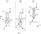
- illustrates a configuration and operation of a subsurface injector suitable for use with grassland according to an example;
- Fig. 11
- illustrates another subsurface injector suitable for use with grassland according to an example;
- Fig. 12
- illustrates a parallel injection device for subsurface injectors suitable for use with grassland according to an example;
- Figs. 13A, 13B
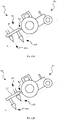
- illustrate an agricultural implement in two stages of a process for deploying farm fertilizer and concurrent anchoring of the agricultural implement in a hillside location according to an example;
- Fig. 14
- illustrates a portable farm fertilizer deployment system manually operable for deploying prepackaged farm fertilizer according to an example;
- Fig. 15A
- illustrates an example of a subsurface injector comprising an additive conduit according to an example;
- Fig. 15B
- illustrates another example of an subsurface injector comprising an additive conduit and suitable for use with grassland according to an example;
- Fig. 16
- schematically illustrates a method for deploying farm fertilizer enclosed in fertilizer pouches according to an example;
- Fig. 17
- illustrates a detail view of an example of a system for deploying farm fertilizer comprising sensors for scanning and tracking fertilizer pouches;
- Fig. 18A
- schematically illustrates an example of a filling system for fertilizer pouches;
- Fig. 18B
- schematically illustrates an example of a big pack for packaging a plurality of fertilizer pouches identified with a batch identifier; and
- Fig. 18C
- schematically illustrates a drum with a batch identifier for holding a string of fertilizer pouches according to an example.
-
Fig. 1 shows a schematic overview of asystem 10 for deploying prepackaged farm fertilizer according to an example. Thesystem 10 comprises ahold 12 configured to contain a plurality offertilizer pouches 14 each containing a predetermined amount of (semi-)liquid farm fertilizer. Thehold 12 is coupled to a retrieval and dispensingsection 16 comprising apouch dispenser 18 for retrieving and dispensing afertilizer pouch 15 towards asubsurface injector 20. The illustratedsystem 10 is configured as a drawbar trailer comprising supportingtires 12t and configured to be towed by an agricultural implement, such as a tractor. - In operation, the
subsurface injector 20 is at least partially inserted below a soil surface S into a subsurface deposition region ofsoil 22 which may be located around 20 cm below the soil surface S and in the following is referred to as "deposition region" 22 solely for the sake of brevity, wherein the depth may be defined with respect to the surface S before or after the injection of said dispensedfertilizer pouch 15. Thesubsurface injector 20 is configured to receive the dispensedpouch 15 and subsequently insert the dispensedpouch 15 into thedeposition region 22 as an injectedfertilizer pouch 15i giving off farm fertilizer to the surrounding soil region, wherein an unsealing unit integrated with the system 10 (not shown inFig. 1 but shown in the following figures) at least partially unseals the dispensedfertilizer pouch 15 to controllably give off farm fertilizer during and/or subsequent to injection. -
Fig. 2A illustrates an agricultural implement 24 as an example of asystem 10 for deploying packaged farm fertilizer. The agricultural implement 24 comprises ahold 12 for containing thefertilizer pouches 14 and is configured, similar to the example ofFig. 1 , as a drawbartrailer comprising tires 12t and adrawbar 26 to be towed along a towing direction T. - A retrieval and dispensing
section 16 retrieves and dispensesfertilizer pouches 14 from thehold 12 towards asubsurface injector 20, in this example schematically depicted as agrubber 28 of a cultivator. The dispensedfertilizer pouch 15 is subsequently at least partially unsealed by an unsealingunit 30 depicted as a roller with puncturing protrusions to puncture and thereby at least partially unseal said dispensedfertilizer pouch 15 introduced into thedeposition region 22. In the illustrated agricultural implement 24, thegrubber 28 is arranged in front of thehold 12 and behind thedrawbar 26, but thegrubber 28 may equally be arranged behind thehold 12 at a trailing side of the agricultural implement 24, although, solely for the sake of brevity and without loss of generality, in the following only embodiments will be illustrated, wherein thesubsurface injectors 20 are arranged close to a front side of the agricultural implement 24. -
Fig. 2B illustrates a cross sectional view of thehold 12 of the agricultural implement 24 schematically depicted inFig. 2A . Thehold 12 comprises anupper portion 12a and alower portion 12b separated by aseparating grid 31 for implementing a sorting section for thefertilizer pouches 14. The spacing of separatingelements 32 of theseparating grid 31 preferably corresponds substantially to a width of thefertilizer pouches 14, such thatfertilizer pouches 14 dropping from theupper portion 12a towards thelower portion 12b are singulated and/or oriented by theseparating grid 31 into rows offertilizer pouches 14 in thelower portion 12b. Thus,fertilizer pouches 14 may be stored and transported in "big packs" containing a large number offertilizer pouches 14 and may be dropped into thehold 12 with a chute (not shown). Theseparating grid 31 can then sort and/or orient the unsorted plurality offertilizer pouches 14 in theupper portion 12a of thehold 12 into ordered streams of laid outfertilizer pouches 14. -
Fig. 2C illustrates a preferred example wherein the separatingelements 32 comprisecurved sheets 32 oriented to face theupper portion 12a with a curved middle portion of saidcurved sheets 32 to limit a risk of structural damage tofertilizer pouches 14 contained in theupper portion 12a of thehold 12. A conveyor 34 (only partially shown) may be provided in thelower portion 12b of thehold 12 to transport thefertilizer pouches 14 separated and/or oriented by said adjacentcurved sheets 32 towards thesubsurface injectors 20. To assist sorting and/or orienting of thefertilizer pouches 14 from theupper portion 12a of thehold 12, the separatingelements 32 may be driven by an ondulating motion O, such as an ondulating motion O along a longitudinal direction of said separatingelements 32, for example along the plane of projection ofFig. 2B . Preferably, the separatingelements 32 are oriented along the longitudinal direction of the agricultural implement 24, such that separated and/or orientedfertilizer pouches 14 are substantially aligned with the movement direction of said agricultural implement 24 during farm fertilizer deployment. -
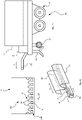
Fig. 3A illustrates a schematic detail view of the retrieval and dispensingsection 16 and acorresponding subsurface injector 20 according to an example. Theconveyor 34 retrievesfertilizer pouches 14 from thehold 12 towards apouch dispensing section 36 comprising apneumatic suction device 38 and a pneumatic discharge jet device 40 for retrieving a selectedfertilizer pouch 14 from theconveyor 34 and dispensing it viabaffle 42 towards thesubsurface injector 20. Thesubsurface injector 20 comprises a guidingsection 44 and ashank 46, such as agrubber 28, configured to till soil during a movement of thesubsurface injector 20 along the tilling direction T. The guidingsection 44 guides the dispensedfertilizer pouch 15 from the retrieval and dispensingsection 16 towards thedeposition region 22. Anadjustable cutting blade 48 at the guidingsection 44 and/or aroller 50 with puncturingprotrusions 52 can be arranged close to thedeposition region 22 to at least partially unseal the dispensedfertilizer pouch 15. The at least partially unsealedfertilizer pouch 15u is then guided by the revolving motion R of theroller 50 towards thedeposition region 22 to give off farm fertilizer towards a surrounding region of soil. Theadjustable cutting blade 48 and/or an adjustable spacer arranged opposite to theroller 50 may be adjusted to control a dispense speed for farm fertilizer from the at least partially unsealedfertilizer pouches 15u into thedeposition region 22 and/or to adapt the unsealingunit 30 to different diameters of thefertilizer pouches 14. - The at least partial unsealing of the dispensed
fertilizer pouches 15 at or close to thedeposition region 22 limits leakage of farm fertilizer and in particular volatile components of said farm fertilizer into components of the agricultural implement 24, onto the soil surface S and/or into upper soil regions. Thus, in some embodiments the unsealingunit 30 is arranged at or close to thedeposition region 22 to limit the leakage of farm fertilizer. However, in some embodiments, wear to the unsealingunit 30 during the tilling of soil is limited by at least partially unsealing a dispensedfertilizer pouch 15 close to or above the soil surface S, such as puncturingfertilizer pouches 14 above the soil surface S. In some embodiments, different components of the unsealingunit 30 are arranged on different height levels, for example in an unsealingunit 30 comprising a puncturing device above the soil surface S and anadjustable cutting blade 48 below the soil surface S. - In
Fig. 3A the guidingsection 44 is schematically illustrated by a guiding plate arranged behind theshank 46. In preferred and in the following described examples, the guidingsection 44 is at least partially tubular, such as a tube arranged behind theshank 46, to assist introduction of the dispensedfertilizer pouch 15 into thedeposition region 22. -
Fig. 3B illustrates a cross sectional view of a guidingsection 44 according to an example in a portion thereof which lies close to or below the soil surface S when thesubsurface injector 20 is in operation. As illustrated inFig. 3A , the guidingsection 44 can be provided with an at least partiallypermeable section 54 comprising spaced bars 56 or wire netting in a trailing direction of thesubsurface injector 20. In the event of a blockage of the guidingsection 44 or inadvertent damage to an enclosing material of thefertilizer pouch 14 in the guidingsection 44, the at least partiallypermeable section 54 allows giving off blocking material accumulating in and occluding the guidingsection 44 to automatically relieve thesubsurface injectors 20 of blockages. -
Fig. 3C illustrates a detail view of the bottom section of asubsurface injector 20 according to an example. Thesubsurface injector 20 comprises ashank 46 behind which, in a trailing direction with respect to the tilling direction T, the guidingsection 44 of thesubsurface injector 20 is arranged. The guidingsection 44 comprises an at least partially permeable section 54 (schematically illustrated by a dashed line), such as thepermeable section 54 illustrated inFig. 3 B . Inside of the guiding section 44 acontrollable dispensing mechanism 58 is arranged comprising arotatable retaining finger 60 to retain and controllably dispense thefertilizer pouches 15. By rotating the retainingfinger 60, thefertilizer pouches 15 may be dispensed in a controlled manner towards theroller 50 to be at least partially unsealed close to thedeposition region 22. Thecontrollable dispensing mechanism 58 controls the rotation of the retainingfinger 60 and may selectively trigger dispensing of afertilizer pouch 15 based on a dispensing command/or at a given or predetermined frequency. Thus, by operating thecontrollable dispensing mechanism 58, the density of dispensed and unsealedfertilizer pouches 15u in thedeposition region 22 may be deterministically controlled. - The skilled person will appreciate that
Figs. 3A and 3C illustrate a plurality ofcontrollable dispensing mechanisms 58 which may individually or in combination perform the controllable dispensing function of the dispensingsection 36 in embodiments. For example, a controllable dispensing offertilizer pouches 14 may be achieved with a controllable conveyor belt speed of theconveyor belt 34, thereby providing a controllable dispensing frequency offertilizer pouches 14 retrieved from thehold 12. Independently, thepneumatic suction device 38 may retrieve and dispensefertilizer pouches 14 by controllably picking and dispensingfertilizer pouches 14 from theconveyor 34 using a modulation of air pressure. In addition, a pneumatic discharge jet device 40 may controllably control injection of afertilizer pouch 14 via thesubsurface injector 20 into thedeposition region 22. Naturally, acontrollable dispensing mechanism 58 for controllably dispensing a dispensedfertilizer pouch 15 may comprise any combination of thecontrollable dispensing mechanisms 58 illustrated inFigs. 3A and 3C . Preferably, one element of saidcontrollable dispensing mechanism 58 is arranged at or close to thesubsurface injector 20, such that a precision or regularity of deposition of the dispensedfertilizer pouch 15 can be high. -
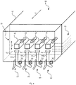
Fig. 4 illustrates a schematic perspective view of arelated system 10 for deploying farm fertilizer enclosed infertilizer pouches 14 stored in ahold 12 according to an example. The storedfertilizer pouches 14 are schematically depicted with dashed lines, indicating a stacked storage of several layers offertilizer pouches 14. A retrieval and dispensingsection 16 comprising a plurality ofpouch dispensers 18 is arranged transverse to the towing direction T of thesystem 10 and is configured to be displaceable at least along a height direction H to allow retrievingfertilizer pouches 14 stored at a corresponding height level within thehold 12. The retrievedfertilizer pouches 14 are dispensed intohoppers 62 coupled tocorresponding subsurface injectors 20, wherein eachsubsurface injector 20 comprises a corresponding unsealing element 30 (depicted as aroller 50 with puncturing protrusions 52). - A sensor (not shown) may also track a retrieval and/or a dispensing of
fertilizer pouches 14, such as to count the number of dispensedfertilizer pouches 15 and may be coupled to a control system to notify an operator of the number of dispensedfertilizer pouches 15, which can be used to track a filling level of thehold 12. - During operation, the
retrieval section 16 can operate thepouch dispensers 18 to synchronously retrieve and dispensefertilizer pouches 14 towards the correspondingsubsurface injectors 20 such that the system may depositfertilizer pouches 15 along parallel tilling lines in the soil. Thus, an operational width comparable to conventional soil tilling with a cultivator can be achieved by providing a plurality ofpouch dispensers 18 in the retrieval and dispensingsection 16, wherein eachpouch dispenser 18 is coupled to acorresponding subsurface injector 20 comprising a tilling element, such as ashank 46 orgrubber 28, of said cultivator to introducefertilizer pouches 14 indeposition regions 22 defined by the tilling of soil by the cultivator in parallel. The subsurface injectors 20 are not depicted in correct perspective to better illustrate the respective components in the illustrated example. In embodiments, the guidingsections 44 should however be aligned with, i.e. arranged behind, a tilling element of a cultivator along the towing direction T. - When the enclosing material of
fertilizer pouches 14 is made of compostable/bio-degradable material, the enclosing material can be deposited with the farm fertilizer into thedeposition region 22. However, as an alternative to a deposition of the dispensedfertilizer pouches 15 in thedeposition region 22, thesystem 10 or the agricultural implement 24 may also be configured to retrieve the enclosing material of thefertilizer pouches 14 after the farm fertilizer is given off in saiddeposition region 22. -
Fig. 5 illustrates a detail view of asubsurface injector 20 of asystem 10 configured to retrieve enclosing material of dispensedfertilizer pouches 15 according to an example. The dispensedfertilizer pouches 15 are introduced along theinjection direction 64, wherein said injection is assisted by a conveyor 66 (depicted with partially dashed lines for better illustration) coupled to aroller 50 with puncturingprotrusions 52, saidroller 50 providing an unsealingunit 30 and being arranged behind ashank 46 of a cultivator below the soil surface S close to thedeposition region 22. A revolving motion R of theroller 50 can in principle be driven by theconveyor 66. A wire netting 54 restraints the path of the dispensedfertilizer pouch 15 and is configured to prevent dispensedfertilizer pouches 15 from remaining in thedeposition region 22. - In operation, a dispensed
fertilizer pouch 15 injected along theinjection direction 64 can come in contact with theroller 50 and can be engaged by the puncturingprotrusions 52 thereby at least partially unsealing said dispensedfertilizer pouch 15 and/or guiding said dispensedfertilizer pouch 15 along a path around the circumference of theroller 50. Along said path, the dispensedfertilizer pouch 15 gives off farm fertilizer into thedeposition region 22 as a substantially localizedfarm fertilizer pocket 70. Close to theroller 50, thewire netting 54 may define anarrow section 68 to squeeze the dispensedfertilizer pouch 15 to assist the deposition of farm fertilizer to thedeposition region 22. Theempty fertilizer pouches 15e can then be retrieved by theconveyor 66 towards arecovery bin 72 above the soil surface S. - In this way, the
system 10 can be compatible with at least partially non-compostable enclosing material or material with long composting times or can enable reuse of said enclosing material of theempty fertilizer pouches 15e subsequent to deployment of the farm fertilizer. -
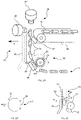
Figs. 6A, 6B and 6C illustrate an alternative way of storing and/or providingfertilizer pouches 14 according to an example. InFig. 6A ,individual fertilizer pouches 14 enclosing a predetermined amount of farm fertilizer are interconnected as astring 74 offertilizer pouches 14 divided by separatingsegments 75. In preferred embodiments, the separatingsegments 75 prevent farm fertilizer exchange betweenadjacent fertilizer pouches 14 and/or are made of substantially the same material as the enclosing material of thefertilizer pouches 14. - Storing
farm fertilizer pouches 14 as astring 74 offertilizer pouches 14 may facilitate handling offertilizer pouches 14 during transport, retrieval and/or subsurface injection of farm fertilizer. For example, and as shown inFig. 6A , thestring 74 offertilizer pouches 14 may be rolled up onto adrum 76 to collectively handle a plurality offertilizer pouches 14.Fertilizer pouches 14 may be retrieved from thedrum 76 by pulling on thestring 74 offertilizer pouches 14 along the feeding direction F. - As illustrated in
Fig. 6B a plurality ofdrums 76a-76e can be aligned in parallel to form a segmented storage of rolled upstrings 74 offertilizer pouches 14. Eachdrum 76a-76e may then independently provide a feed offertilizer pouches 14 for acorresponding subsurface injector 20 for parallel deployment offarm fertilizer pouches 14. However, thesystem 10 may also comprise a sensor (not shown) to trackfertilizer pouches 14 retrieved from thehold 12 and may accordingly switch betweendrums 76a-76e when an actively unrolleddrum 76a-76e is determined to have been fully unrolled or may notify an operator to switch said actively unrolleddrum 76a-76e. - As an alternative storage configuration,
Fig. 6C illustrates folding up thestring 74 offertilizer pouches 14 in ahold 12, thereby storing astring 74 offertilizer pouches 14 independently of adrum 76. The foldedstring 74 offertilizer pouches 14 may equally be retrieved from thehold 12 by engaging one end of thestring 74 with theconveyor 34 and thus retrievingfertilizer pouches 14 from thehold 12 according to the sequence offertilizer pouches 14 given by thestring 74 offertilizer pouches 14. -
Fig. 7A and 7B illustrate two schematic examples ofsubsurface injectors 20 operated with astring 74 offertilizer pouches 14. - In
Fig. 7A , thestring 74 offertilizer pouches 14 is introduced into ahopper 62 associated with thesubsurface injector 20 to provide a sequence of sequentially advancingfertilizer pouches 14 separated by separatingsegments 75. Thefertilizer pouches 14 advance via a guidingsection 44 of thesubsurface injector 20 arranged behind ashank 46 towards aroller 50. Theroller 50 is equipped with separatingblades 78, said separatingblades 78 being distributed around the circumference of theroller 50 at substantially equal spacing. During a revolving motion R of theroller 50, theseparating blades 78 engage the separatingsegments 75 to cut the separatingsegments 75 and thereby singulateindividual fertilizer pouches 14 from thestring 74 offertilizer pouches 14. In the illustrated example, theroller 50 is further equipped with puncturingprotrusions 52 to at least partially unseal the separated fertilizer pouches 15s. Thus,fertilizer pouches 14 from thestring 74 offertilizer pouches 14 may be singulated and distributed controllably in thedeposition region 22. The skilled person will however appreciate that the singulation of thefertilizer pouches 14 can be performed independently of the unsealing of the fertilizer pouches as well as performed at any stage between thehold 12 and the deposition region ofsoil 22, such as in the retrieval and dispensingsection 16. -
Fig. 7B illustrates another example of asubsurface injector 20 operated with astring 74 offertilizer pouches 14, whereinfertilizer pouches 14 are retrieved after giving off farm fertilizer into a pocket offarm fertilizer 70 in thedeposition region 22. In this example, thesubsurface injector 20 is not equipped with any singulating unit, such as theseparating blades 78, but thestring 74 offertilizer pouches 14 rather loops around aroller 50 towards arecovery bin 72 along a path following the revolving motion R of theroller 50 towards theretrieval direction 80. - In operation, the revolving motion R of the
roller 50 pulls thestring 74 offertilizer pouches 14 from thehold 12 towards thedeposition region 22.Fertilizer pouches 14 contacting theroller 50 can be squeezed by the mechanical engagement and/or punctured by puncturingprotrusions 52 arranged on theroller 50 to give off farm fertilizer into a pocket offarm fertilizer 70 in thedeposition region 22. Theempty fertilizer pouches 15e can then be retrieved as astring 74 ofempty fertilizer pouches 15e towards arecovery bin 72. -
Fig. 8 illustrates ahold configuration 12 suitable for utilization with asubsurface injector 20 for astring 74 offertilizer pouches 14 as depicted in the example ofFig. 7B . Thehold 12 comprises a plurality ofdrums 76a-c for storingstrings 74 offertilizer pouches 14 and arecovery drum 82 arranged above aconveyor 34. Thedrums 76a-c are unrolled to providestrings 74 offertilizer pouches 14 fed via theconveyor 34 and along theinjection direction 64 towards thesubsurface injectors 20 to introduce farm fertilizer into thedeposition region 22 at or below the soil surface S (not shown, but shown inFig. 7B ). After giving off the farm fertilizer enclosed in thefertilizer pouches 14 of thestring 74 offertilizer pouches 14,empty fertilizer pouches 15e are recovered as astring 74 ofempty fertilizer pouches 15e along theretrieval direction 80. Theconveyor 34 advances thestring 74 ofempty fertilizer pouches 15e towards therecovery drum 82 to roll up the interconnectedempty fertilizer pouches 15e in thehold 12. - In
Fig. 8 , thestring 74 of fertilizer pouches is supplied towards a front of thehold 12 with respect to the towing direction T. However, thestring 74 offertilizer pouches 14 may equally be supplied towards the back of thehold 12 without loss of generality. In this case, the arrangement of thedrums 76a-c and theconveyor 34 may be modified accordingly. - For example, in
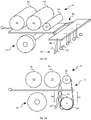
Figs. 9A, 9B two exemplary configurations forsystems 10 for deploying farm fertilizer withfertilizer pouches 14 supplied towards the back of ahold 12 are schematically illustrated, wherein saidsystems 10 each comprisedrums strings 74 offertilizer pouches 14 and arecovery drum 82 for retrievingempty fertilizer pouches 15e. - In
Fig. 9A , a plurality of subsurface injectors 20 (only onesubsurface injector 20 provided with reference signs) are connected to ahold 12 via ahinge 83, such as a three-point hinge, wherein thesubsurface injectors 20 are illustrated withshanks 46 arranged in front of guidingsections 44 and comprising aroller 50 close to thedeposition region 22. Thehinge 83 may control a relative insertion depth of thesubsurface injectors 20 to establish a depth of thedeposition region 22. For example, thehinge 83 may be pneumatically driven to modulate a relative height of thesubsurface injectors 20 with respect to thehold 12. Therecovery drum 82 is arranged close to a rear of thehold 12 to retrieve astring 74 ofempty fertilizer pouches 15e (not shown) from thesubsurface injectors 20. In operation, saiddrum string 74 offertilizer pouches 14 towards thesubsurface injectors 20 while astring 74 ofempty fertilizer pouches 15e may be retrieved to be rolled up onto the recovery drum 82 (not shown). -
Fig. 9B illustrates another exemplary configuration of asystem 10, wherein asubsurface injector 20 is integrated beneath thehold 12, with arecovery drum 82 arranged at or close to a rear side of thesubsurface injector 20. In this way, astring 74 ofempty fertilizer pouches 15e may be retrieved behind thesubsurface injectors 20, thereby spatially separating and limiting an interference of thestring 74 ofempty fertilizer pouches 15e and astring 74 of retrievedfertilizer pouches 14. - The
system 10 or agricultural implement 24 for deployment of farm fertilizer enclosed infertilizer pouches 14 may also be used independently of a tilling of soil, such as in the case of deployment of farm fertilizer on grassland. The interconnected turf on grassland can restrict such tilling due to mechanical resistance as well as disadvantageous damage to the roots. -
Fig. 10 illustrates asubsurface injector 20 compatible with subsurface farm fertilizer deployment independently of a tilling of soil according to an example, wherein the operation of thesubsurface injector 20 a is illustrated withsteps 1 to 5 of a subsurface injection sequence. - The
subsurface injector 20 comprises a puncturinghead 84 depicted as a substantially conic and segmented puncturing device having atip 85 oriented towards the soil surface S and configured to pierce the soil surface S. The puncturinghead 84 is coupled to a guidingsection 44 comprising an outerprotective layer 86 and a guidingtube 88 coupled to the puncturinghead 84 and arranged inside of the protectinglayer 86 for guidingfertilizer pouches 14 into thedeposition region 22. Thesubsurface injector 20 is then configured to be vertically displaced to pierce the soil surface S and to introduce a dispensedfertilizer pouch 15 into thedeposition region 22, such as by performing the subsurface injection sequence illustrated by thesteps 1 to 5. - In the first step, the
subsurface injector 20 is arranged above the soil surface S and moved to a desired deposition location. In the second step, thesubsurface injector 20 pierces the soil surface S with the puncturinghead 84 to move the puncturinghead 84 towards thedeposition region 22. In the third step, thesegments head 84 are laterally displaced, thereby exposing a bottom side of the guidingtube 88 to thedeposition region 22. In the fourth step, a dispensedfertilizer pouch 15 is introduced into thedeposition region 22 via said bottom side of the guidingtube 88. In the fifth step, thesubsurface injector 20 is retracted from the soil above the soil surface S. - As in the previous examples, the
subsurface injector 20 may be equipped with an unsealingunit 30 to at least partially unseal the dispensedfertilizer pouch 15 at or close to thedeposition region 22. In some examples, an unsealingunit 30 is integrated with the puncturinghead 84 and is configured to unseal the dispensedfertilizer pouch 15 during exposing of the guidingtube 88, such as by arranging puncturing or cutting devices in at least one of thesegments fertilizer pouch 15 during a lateral displacement of thesegments head 84. -
Fig. 11 illustrates asubsurface injector 20 related to the example ofFig. 10 according to another example. Thesubsurface injector 20 comprises asegmented puncturing head 84 comprisingsegments fertilizer pouch 15 introduced along theinjection direction 64 via the guidingtube 88 into thedeposition region 22. Theillustrated steps 1 to 3 can replacesteps Fig. 10 and illustrate the deposition of farm fertilizer into thedeposition region 22 and the subsequent retrieval of theempty fertilizer pouch 15e. - In the first step, the puncturing
head 84 is opened by laterally displacing thesegments head 84 pierces the soil surface S and is located close to the deposition region 22 (lateral motion of segments illustrated with black arrows). In the second step, thesegments head 84 to engage the dispensedfertilizer pouch 15, thereby at least partially unsealing and/or squeezing the dispensedfertilizer pouch 15 to give off farm fertilizer into a pocket offarm fertilizer 70 in thedeposition region 22. In the third step, theempty fertilizer pouch 15e is recovered, such as by a pneumatic suction device aspiring air from the guidingtube 88 of thesubsurface injector 20, thereby retrieving theempty fertilizer pouch 15e from thesubsurface injector 20 towards a recovery bin 72 (not shown). Subsequently, thesubsurface injector 20 can be retracted from the soil above the soil surface S to advance thesubsurface injector 20 to a subsequent farm fertilizer deposition location. -
Fig. 12 illustrates aparallel injection device 90 for parallel operation of subsurface injectors with puncturingheads 84 for piercing the soil surface S according to an example. The illustratedparallel injection device 90 comprises acoupling member 92 provided with a plurality ofsubsurface injectors 20 as depicted inFigs. 10 and11 . Theparallel injection device 90 may be towed via adrawbar 26 behind an agricultural implement and each of thesubsurface injectors 20 may be coupled to acorresponding pouch dispenser 18 to dispensefertilizer pouches 14 retrieved from a hold 12 (not shown). In addition, thedevice 90 may also be arranged in front of an agricultural implement. By synchronously operating thesubsurface injectors 20 to pierce the soil surface S and to introduce dispensedfertilizer pouches 15 into thedeposition region 22, parallel injection offertilizer pouches 14 can be achieved according to an operational width given substantially by the width of thecoupling member 92. -
Figs. 13A, 13B illustrate an agricultural implement 24 with adevice 90 as shown inFig. 12 in two stages of a process of deploying farm fertilizer and concurrent anchoring of the agricultural implement 24 in a hillside location according to an example. As schematically illustrated, thesubsurface injectors 20 can be configured to pierce the soil surface S alternatingly to anchor thedevice 90 in turns. InFig. 13A , a first row ofsubsurface injectors 20b pierces the soil surface S to thereby anchor an agricultural implement 24, such astractor 93, with respect to a slope defined by the soil surface S. In a subsequent step illustrated inFig. 13B , a second row ofsubsurface injectors 20a may be driven to pierce the soil surface S and to lie beneath the soil surface S to anchor saidtractor 93 in a different position. - The
subsurface injectors 20a, b may be controllably displaceable along the towing direction T to allow a constant movement of the agricultural implement 24 and/or to provide continuous anchoring of thedevice 90 during deployment of farm fertilizer. As illustrated, thesubsurface injectors 20 may be divided into sets ofsubsurface injectors device 90. Thus, the sets ofsubsurface injectors device 90 and advancing along the towing direction T in turns in a controlled manner. Thus, by operating thesubsurface injectors device 90 may provide anchoring to assist deployment of farm fertilizer in hillside locations. -
Fig. 14 illustrates another embodiment of asystem 10 for deploying prepackaged farm fertilizer according to an example, wherein thesystem 10 is a portable farmfertilizer deployment system 10 manually operable to introduce said farm fertilizer into adeposition region 22, whereinsteps 1 to 3 illustrate an exemplary subsurface injection sequence. To operate thesystem 10,fertilizer pouches 14 can be initially loaded into a holding portion of the guidingsection 44, thesystem 10 can then be operated with ahandle 89 to pierce the soil surface S with thesubsurface injector 20, and thefertilizer pouch 14 may be retrieved from the holding portion and dispensed, such as by operating a switch or a crank (not depicted) integrated with thesystem 10 at or close to thehandle 89, to introduce thefertilizer pouch 14 into thedeposition region 22 in a controllable manner. - As in previously described examples, the
subsurface injector 20 of thesystem 10 can comprise a puncturinghead 84 depicted as a substantially conic and segmented puncturing device having atip 85 oriented towards the soil surface S and configured to pierce the soil surface S. A guidingsection 44 comprises a guidingtube 88 coupled to the puncturinghead 84 for guidingfertilizer pouches 14 into thedeposition region 22. Thesubsurface injector 20 is then configured to be vertically displaced via thehandle 89 to pierce the soil surface S and to introduce a dispensedfertilizer pouch 15 into thedeposition region 22, such as via the illustrated sequence ofsteps 1 to 3. - In the first step, the puncturing
head 84 pierces the soil surface S with thetip 85 to move the puncturinghead 84 towards thedeposition region 22. In the second step, thesegments head 84 are laterally displaced, thereby exposing a bottom side of the guidingtube 88 to thedeposition region 22, such that a dispensedfertilizer pouch 15 may be introduced into thedeposition region 22 via said bottom side of the guidingtube 88. Said lateral displacement may be manually operable with a corresponding displacement mechanism and/or may be at least partially mediated by a shape and/or a mounting of thesegments head 84, said shape and/or mounting mechanically coupling the introduction of thesubsurface injectors 20 beneath the soil surface S and the lateral displacement of thesegments subsurface injector 20 is retracted from the soil above the soil surface S, while the dispensedfertilizer pouch 15 remains in thedeposition region 22. - As in the previous examples, the
subsurface injector 20 may be equipped with an unsealingunit 30 to at least partially unseal the dispensedfertilizer pouch 15 at or close to thedeposition region 22. In some examples, an unsealingunit 30 is integrated with the puncturinghead 84 and is configured to unseal the dispensedfertilizer pouch 15 during exposing of the guidingtube 88, such as by arranging puncturing or cutting devices in at least one of thesegments fertilizer pouch 15 during a lateral displacement of thesegments head 84. -
Fig. 15A illustrates another example of asubsurface injector 20 comprising a guidingsection 44 arranged behind ashank 46 to be operable as a tilling element. Dispensedfertilizer pouches 15 are introduced along theinjection direction 64 into thedeposition region 22 and are engaged by aroller 50 to at least partially unseal and/or guide the dispensedfertilizer pouches 15 into thedeposition region 22. In addition, thesubsurface injector 20 comprises anadditive conduit 94 configured to dispenseadditives 96, such as reagents, into thedeposition region 22. - The
additives 96 dispensed by theconduit 94 may be additional fertilizer components, such as plant nutrients, and/or may comprise reagents to react with the enclosing material of thefertilizer pouches 14 and/or the farm fertilizer enclosed in thefertilizer pouches 14. Thus, said reagents may assist composting and/or unsealing of the enclosing material of thefertilizer pouches 14 and/or may react with the farm fertilizer introduced into thedeposition region 22 to improve plant growth. - In the illustrated example, the
additive conduit 94 is equipped with an outlet close to theroller 50, such that theadditives 96 are brought in contact with the dispensedfertilizer pouch 15 during the revolving motion R of theroller 50. However, the skilled person will appreciate that theadditives 96 may also be injected directly into thedeposition region 22 or dispensed onto the dispensedfertilizer pouches 15 at or above the soil surface S. Moreover, theconduit 94 may also comprise a valve to selectively dispenseadditives 96 into thedeposition region 22 synchronously with the dispensing offertilizer pouches 14. -
Fig. 15B illustrates another example of asubsurface injector 20 comprising a puncturinghead 84 to pierce the soil surface S and to introduce a dispensedfertilizer pouch 15 into thedeposition region 22 similar to the examples illustrated inFigs. 10 to 14 . Aconduit 94 is integrated with the guidingtube 88 for introducing the dispensedfertilizer pouches 15 into thedeposition region 22. Theconduit 94 injectsadditives 96 into thedeposition region 22 when the puncturinghead 84 is operated to release a dispensedfertilizer pouch 15 into thedeposition region 22. A valve may be operated to perform said injection ofadditives 96 into thedeposition region 22 synchronously with the introduction of the dispensedfertilizer pouch 15 into thedeposition region 22. - In some embodiments,
additives 96 can also be integrated in an outer material layer of thefertilizer pouch 15. The farm fertilizer enclosed in thefertilizer pouch 15 may then react with theadditives 96 in the outer material layer of thefertilizer pouch 15 following at least partial unsealing of thefertilizer pouch 15 by the unsealingunit 30 or at least partial composting of thefertilizer pouch 15. In some embodiments, an outer material layer offertilizer pouch 15 encloses both theadditives 96 and an inner material layer enclosing the farm fertilizer, and the unsealingunit 30 is configured to unseal both the outer and the inner material layer synchronously or sequentially to give offadditives 96 and the farm fertilizer into thedeposition region 22. -
Fig. 16 schematically illustrates a method for deploying farm fertilizer enclosed infertilizer pouches 14 with an agricultural implement 24, in particular using asystem 10 as previously described, saidfertilizer pouches 14 each enclosing a pre-determined amount of said farm fertilizer. The method comprises the step of retrieving and dispensing afertilizer pouch 14 from areservoir 12 containing a plurality offertilizer pouches 14 in a controllable manner (step S10). The method further comprises the steps of receiving afertilizer pouch 15 dispensed from said reservoir 12 (step S12), and introducing a pre-determined amount of said farm fertilizer in thefertilizer pouch 15 into a subsurface region of soil 22 (step S14). - In accordance with the preceding description of
systems 10 for deploying farm fertilizer, the method may comprise further steps for implementing the functionality of or using any one of the examples offertilizer deploying systems 10 andagricultural implements 24 or components thereof for deploying farm fertilizer enclosed infertilizer pouches 14. -
Fig. 17 illustrates a detail view of an example of asystem 10 for deploying farm fertilizer similar to thesystem 10 illustrated inFig. 3A , further illustrating ascanning sensor 98 and one ormore presence sensors 100a-c to trackfertilizer pouches 14. - As illustrated in
Fig. 17 , thescanning sensor 98 may be arranged in the receiving and dispensingsection 36 of thesystem 10, such as close to a receivingsection 36 arranged at thehold 12 or close to adispensing section 36 close to the one ormore subsurface injectors 20. Thescanning sensor 98 may be used to scan an identifier imprinted on thefertilizer pouches 14, such as a print and/or an impression and/or a cutout and/or a molding in the enclosing material of thefertilizer pouches 14. Preferably, the identifier features an optically discernable code and thescanning sensor 98 is arranged and configured to scan the optically discernable code by an optical measurement of the enclosing material of thefertilizer pouches 14. For example, thescanning sensor 98 may comprise a camera and/or an optical scanning system based on LED- or laser-light to detect the optically discernable code by a contactless measurement of the optical properties of the enclosing material. - Additionally or alternatively, the
scanning sensor 98 may be arranged in the one ormore subsurface injectors 20, such as along a guidingsection 44 of the one ormore subsurface injectors 20 and/or at ahopper 62 associated with the one or more subsurface injectors 20 (not shown). However, thescanning sensor 98 should be arranged above the soil surface S to avoid staining of thescanning sensor 98 and to ensure continuous scanning of the identifier offertilizer pouches 14 during deploying the farm fertilizer. - The identifier may be associated with a fertilizer property of the
fertilizer pouch 14, such as an origin and/or a characteristic of the content of thefertilizer pouch 14, and thesystem 10 may be adapted to store the scanned identifier for documentation. For example, thesystem 10 may comprise a controller and a memory (not shown), and the controller may be configured to receive the identifier from thescanning sensor 98 and store the identifier along with contextual data, such as the position and/or speed and/or deploying frequency of thesystem 10. Thesystem 10 may also adapt a deployment modality for deploying farm fertilizer based on the scanned identifier and the contextual data. For example, a deployment frequency of thesystem 10, such as the rotation frequency of theroller 50 or a speed of theconveyor 34, may be adapted based on the content of thefertilizer pouch 14 as determined from the identifier. Preferably, the deployment modality is based on the fertilizer property of thefertilizer pouch 14 and the present location or velocity of thesubsurface injectors 20, e.g. as determined from GPS data, such as to obtain a predetermined deployment density of plant nutrients. - The
system 10 may further comprise one ormore presence sensors 100a-c (illustrated inFig. 17 at different potential locations with dashed lines). The one ormore presence sensors 100a-c are adapted to detect a presence of afertilizer pouch 14 in its vicinity, such as to track an advance of thefertilizer pouches 14 through the receiving and dispensingsection 36 and/or thesubsurface injectors 20. For example, the one ormore presence sensors 100a-c may comprise optical sensors, such as cameras, diodes, photocells, CCD sensor elements, and the like, and may comprise corresponding light sources (e.g. LEDs, Lasers, etc.), and/or may comprise mechanical sensors, such as mechanically activated switches, scales, pressure plates, and the like, and/or electrical sensors, such as capacitive sensors, RF-sensors, RF-tag reading sensors and the like, to detect a presence of afertilizer pouch 14 in the vicinity of the one ormore presence sensors 100a-c. The one ormore presence sensors 100a-c may be arranged in the receiving and dispensingsection 36, as illustrated for thepresence sensor 100a, or maybe arranged in thesubsurface injectors 20, such as along the guiding section 44 (as illustrated forpresence sensor 100b) or at the roller 50 (as illustrated for presence sensor 100c). As the one ormore presence sensors 100a-c may not need to perform optical scanning of the identifier, the one or more presence sensors 1ooa-c may also be arranged below thesoil surface 100a-c. Thesystem 10 may also comprise a plurality ofpresence sensors 100a-c arranged before and/or after thescanning sensor 98. For example, afirst presence sensor 100a-c may be arranged in the receiving and dispensingsection 36 closer to thehold 12 than thescanning sensor 98, and asecond presence sensor 100a-c may be arranged past thescanning sensor 98, such as at or close to the one ormore subsurface injectors 20, to track thefertilizer pouches 14 in thesystem 10 before and after passing thescanning sensor 98. - It is noted that the example of
Fig. 17 illustrates asystem 10 for deploying separatedfertilizer pouches 14. However, the skilled person will appreciate that ascanning sensor 98 and/or the one ormore presence sensors 100a-c may equally be employed withstrings 74 offertilizer pouches 14 to scan an identifier imprinted onfertilizer pouches 14 or imprinted in a separatingsegment 75 between concatenatedfertilizer pouches 14, and/or to detect a presence of afertilizer pouch 14 at the position of the one ormore presence sensors 100a-c. -
Fig. 18A illustrates an example of a filling system forfertilizer pouches 14. The filling system comprises aninjection element 102 for injecting liquid farm fertilizer into sections of enclosingmaterial 104. The enclosingmaterial 104 may be guided byrollers 106 to aseparating element 108, wherein the separatingelement 108 is configured to close opposing sides of the enclosingmaterial 104 to formfertilizer pouches 14 enclosing a predetermined amount of farm fertilizer separated byclosed separating segments 75. The filling system may comprise an imprinting element to imprint an identifier onto the enclosingmaterial 104. For example, the separatingelement 108 may imprint an identifier on the separatingsegments 75, such as by embossing the enclosingmaterial 104 or by printing the identifier on the enclosingmaterial 104. Said identifier may be associated with a certain property characterizing the farm fertilizer, such as the biological origin of farm fertilizer, e.g. whether the farm fertilizer includes feces which may originate from pigs, cows, sheep or other animals, or whether the farm fertilizer includes other manure sources, such as compost. - In some examples, the filling system comprises a
detection element 109 to detect a fertilizer property of the farm fertilizer enclosed by the enclosingmaterial 104 as a measured fertilizer property, such as a water content or a nutrition value of the farm fertilizer enclosed in thefertilizer pouch 14. - The fertilizer property may be recorded with the identifier imprinted on the enclosing
material 104 for documentation. As farm fertilizer is usually a biological product and may therefore be subject to large variation in view of ambient variables, such as a degree of outgassing, UV exposure and biological origin, recording the measured fertilizer property of farm fertilizer enclosed in thefertilizer pouches 14 with an identifier of afertilizer pouch 14 or an identifier of a plurality offertilizer pouches 14 may facilitate accurate documentation of packaged and/or deployed farm fertilizer. In some embodiments, the identifier includes the fertilizer property, such as a code representing a certain measured fertilizer property or the origin of the farm fertilizer enclosed in thefertilizer pouch 14. The identifier may be arranged on the front and tail sections of eachfertilizer pouch 14, such as at the edges of the separatingsegments 75, to allow reading of the identifier on both sides of thefertilizer pouch 14. - A plurality of
fertilizer pouches 14 may be packaged together along with abatch identifier 112 characterizing a plurality offertilizer pouches 14 as shown in the examples ofFigs. 18B, 18C . - In
Fig. 18B , a plurality of fertilizer pouches 14 (not shown) are packaged in abig pack 110 as a batch offertilizer pouches 14, wherein thebig pack 110 comprises abatch identifier 112. Saidbatch identifier 112 may feature a readable code, such as an optically readable code, e.g. a barcode, or a radio frequency readable code, such as an RFID tag. Thebatch identifier 112 may be associated with common properties of the plurality offertilizer pouches 14. As an example, thebatch identifier 112 may include information on a characteristic of the enclosingmaterial 104, such as a composition or thickness of the enclosingmaterial 104, or a packaging date, such as to document an expected expiry date of the plurality offertilizer pouches 14. However, the skilled person will appreciate that this information may also be included in an identifier associated with asingle fertilizer pouch 14. - Moreover, the
batch identifier 112 may also contain information regarding the total content of the plurality offertilizer pouches 14, such as the quantity offertilizer pouches 14 stored in thebig pack 110 and/or a total plant nutrient value and/or total water content of the plurality offertilizer pouches 14. - As illustrated in
Fig 18C , adrum 76 for holding astring 74 of fertilizer pouches 14 (not shown) may equally comprise abatch identifier 112 which may also feature a readable code. As a further example, thebatch identifier 112 may contain information on the number and/or size and/or separation distance offertilizer pouches 14 of thestring 74 arranged on thedrum 76. - Said
batch identifier 112 may be read by a scanning member (not shown) of thesystem 10 for documentation of deployed farm fertilizer. For example, a user may scan an optically scannable code with a scanning device and transmit information pertaining to the scannedbatch identifier 112 to the controller of thesystem 10. Alternatively or additionally, thesystem 10 may comprise a scanning member, such as an optical scanning member or an RF-scanning member, to scan thebatch identifier 112 of abig pack 110 or adrum 76 in thehold 12, and thesystem 10 may automatically detect properties of the plurality offertilizer pouches 14 stored in thebig pack 110 or arranged on thedrum 76. - The description of the preferred embodiments and the figures merely serve to illustrate the invention and the beneficial effects associated therewith, but should not be understood to imply any limitation. The scope of the invention is to be determined solely by the appended claims.
-
- 10
- system
- 12
- hold
- 12t
- supporting tires
- 12a
- upper portion of hold
- 12b
- lower portion of hold
- 14
- fertilizer pouch
- 15
- dispensed fertilizer pouch
- 15i
- injected fertilizer pouch
- 15u
- at least partially unsealed fertilizer pouch
- 15e
- empty fertilizer pouch
- 15s
- separated fertilizer pouches
- \16
- retrieval and dispensing section
- 18
- pouch dispenser
- 20
- subsurface injector
- 22
- subsurface deposition region of soil/deposition region
- 24
- agricultural implement
- 26
- drawbar
- 28
- grubber
- 30
- unsealing unit
- 31
- separating grid
- 32
- separating elements
- 34
- conveyor
- 36
- dispensing section
- 38
- pneumatic suction device
- 40
- pneumatic discharge jet
- 42
- baffle
- 44
- guiding section
- 46
- shank
- 48
- adjustable blade
- 50
- roller
- 52
- puncturing protrusion
- 54
- permeable portion
- 56
- guiding bar of permeable portion
- 58
- controllable dispensing mechanism
- 60
- rotatable retaining element
- 62
- hopper
- 64
- injection direction
- 66
- conveyor
- 68
- narrow section
- 70
- fertilizer pocket
- 72
- recovery bin
- 74
- string of fertilizer pouches
- 75
- separating segments
- 76
- drum
- 76a-c
- drum segments
- 78
- separating blade
- 80
- retrieval direction
- 82
- recovery drum
- 83
- hinge
- 84
- puncturing head
- 84a, b
- puncturing head segments
- 86
- outer protective layer
- 88
- guiding tube
- 89
- handle
- 90
- parallel injection device
- 92
- coupling member
- 93
- tractor
- 94
- additive conduit
- 96
- additives
- 98
- scanning sensor
- 100a-c
- presence sensor
- 102
- injection element
- 104
- enclosing material
- 106
- roller
- 108
- separating element
- 110
- big pack
- 112
- batch identifier
- S
- soil surface
- T
- towing direction
- O
- ondulating motion
Claims (15)
- An agricultural fertilizer deploying system (10) configured for deploying at least partially liquid farm fertilizer, in particular an agricultural implement (24), said system (10) comprising:- a hold (12) configured to retain a plurality of fertilizer pouches (14), said fertilizer pouches (14) each enclosing a pre-determined amount of said at least partially liquid farm fertilizer;- a retrieval and dispensing section (16) coupled to said hold (12), said retrieval and dispensing section (16) being configured to retrieve said fertilizer pouches (14) from the hold (12) and to dispense a retrieved fertilizer pouch (15) in a controllable manner;- a cultivator, and- one or more subsurface injectors (20) each coupled to said retrieval and dispensing section (16), said subsurface injectors (20) being configured to receive the dispensed fertilizer pouch (15) from said retrieval and dispensing section (16) and to introduce the pre-determined amount of said farm fertilizer into a subsurface deposition region of soil (22) more than 5 cm below the soil surface;wherein each subsurface injector (20) comprises a tube (44) arranged behind a tilling element (28, 46) of the cultivator;wherein each tube (44) is configured to receive the dispensed fertilizer pouch (15) and guide the dispensed fertilizer pouch (15) to said subsurface deposition region of soil (22).
- The system (10) of claim 1, wherein said tilling element (28, 46) is a shank (46) or grubber (28); and/or
wherein the tube (44) comprises a permeable section (54) at least in a portion of the tube (44) arranged below ground level, the permeable section (54) being liquid permeable at least in a trailing direction with respect to a tilling direction (T) of the cultivator, said permeable section (54) in particular comprising spaced bars (56) or wire netting. - The system (10) of claim 1 or 2, wherein the system comprises at least one unsealing unit (30) arranged at or close to the one or more subsurface injectors (20), said unsealing unit (30) being configured to at least partially unseal the dispensed fertilizer pouch (15), allowing said fertilizer pouch (14) to give off said farm fertilizer into the subsurface deposition region of soil (22),wherein the unsealing unit (30) is in particular configured to unseal said dispensed fertilizer pouch (15) close to or below ground-level after said dispensed fertilizer pouch (15) has been dispensed from said retrieval and dispensing section (16),wherein each unsealing unit (30) preferably comprises a roller (50) configured to unseal the dispensed fertilizer pouch (15) using a protrusion (52) and/or blade (48) arranged on and/or opposite to the roller (50) by one or more of puncturing, cutting, ripping and breaking the dispensed fertilizer pouch (15) during a revolving motion (R) of the roller (50), wherein said revolving motion (R) causes and/or assists an engagement of said blade (48) and/or protrusion (52) with the dispensed fertilizer pouch (15), said roller (50) being preferably arranged in a portion of the one or more subsurface injectors (20) lying at or below the surface (S) of the soil tilled by the cultivator;wherein the system (10) most preferably comprises a conveyor (34) coupled to the roller (50) to assist introduction of the dispensed fertilizer pouch (15) into the subsurface deposition region of soil (22).
- The system (10) of claim 3, wherein the fertilizer pouches (14) comprise an enclosing material to enclose said farm fertilizer, wherein the unsealing unit (30) is configured to empty the dispensed fertilizer pouch (15), and wherein the system (10) further comprises a recovery unit configured to prevent deposition of the enclosing material of the dispensed fertilizer pouch (15) in the soil and to recover empty fertilizer pouches (15e), preferably in a recovery bin (72, 82) or onto a drum,wherein the system in particular further comprises a plurality of at least liquid permeable retainers (54, 68), in particular wire netting, said retainers (54, 68) being arranged close to a bottom side of each subsurface injector (20) to prevent the enclosing material of the dispensed fertilizer pouch (15) to remain in the soil, while the dispensed fertilizer pouch (15) is emptied in the subsurface deposition region of soil (22); and/orwherein the recovery unit in particular comprises at least one of a pneumatic device and a conveyor (66) integrated with the subsurface injector (20) to recover empty fertilizer pouches (15e) from the one or more subsurface injectors (20).
- An agricultural fertilizer deploying system (10) configured for deploying at least partially liquid farm fertilizer, in particular an agricultural implement (24), said system (10) comprising:- a hold (12) configured to retain a plurality of fertilizer pouches (14), said fertilizer pouches (14) each enclosing a pre-determined amount of said at least partially liquid farm fertilizer;- a retrieval and dispensing section (16) coupled to said hold (12), said retrieval and dispensing section (16) being configured to retrieve said fertilizer pouches (14) from the hold (12) and to dispense a retrieved fertilizer pouch (15) in a controllable manner; and- one or more subsurface injectors (20) each coupled to said retrieval and dispensing section (16), said subsurface injectors (20) being configured to receive the dispensed fertilizer pouch (15) from said retrieval and dispensing section (16) and to introduce the pre-determined amount of said farm fertilizer into a subsurface deposition region of soil (22) more than 5 cm below the soil surface;wherein said subsurface injectors (20) each comprise a puncturing head (84), wherein the system (10) is configured to introduce the dispensed fertilizer pouch (15) into the subsurface deposition region of soil (22) during a vertical subsurface injection sequence of said subsurface injectors (20), said subsurface injectors (20) being configured to:- penetrate the soil surface (S) with the puncturing head (84) of the subsurface injector (20);- release the dispensed fertilizer pouch (15) into the subsurface deposition region of soil (22);- retract the puncturing head (84) above the soil surface (S).
- The system (10) of claim 5, wherein the puncturing head (84) is operable to displace soil in the subsurface deposition region of soil (22).
- The system (10) of claim 5 or 6, wherein an unsealing unit (30) is configured to at least partially unseal the dispensed fertilizer pouch (15) synchronously with the vertical subsurface injection sequence of the subsurface injectors (20) allowing said fertilizer pouch (14) to give off said farm fertilizer into the subsurface deposition region of soil (22), wherein the unsealing unit (30) in particular comprises unsealing members at or close to said puncturing head (84) of each subsurface injector (20).
- The system (10) of any one of the preceding claims, said system (10) being configured for deploying at least partially organic fertilizer, in particular comprising manure and/or fermentation substrate.
- The system (10) of any one of the preceding claims, further comprising a conveyor (34) to guide the plurality of fertilizer pouches (14) from the hold (12) to said retrieval and dispensing section (16); and/or
wherein said retrieval and dispensing section (16) comprises one or more controllable dispensing mechanisms (58) configured to selectively dispense a fertilizer pouch (14) retrieved by said retrieval and dispensing section (16), said one or more controllable dispensing mechanisms (58) in particular comprising at least one of a pneumatic suction device (38), a pneumatic discharge jet (40) and a hatch (60). - The system (10) of any one of the preceding claims, wherein the one or more subsurface injectors (20) are configured to introduce the dispensed fertilizer pouch (15) into the subsurface deposition region of soil (22), wherein said subsurface deposition region of soil (22) is in particular located in a range of 5 cm to 35 cm, preferably of 10 cm to 30 cm, below the soil surface (S); and wherein the system (10) in particular further comprises a position recording unit to record the position of the dispensed fertilizer pouch (15) introduced into the subsurface deposition region of soil (22); and/or wherein said retrieval and dispensing section (16) is configured to controllably dispense the retrieved fertilizer pouch (15) based on a position of the subsurface injectors (20), in particular based on a traveled distance of an associated subsurface injector (20) since the last selective dispensing of a fertilizer pouch (14);and/or further comprising a position determining unit, wherein said retrieval and dispensing section (16) is configured to trigger dispensing the fertilizer pouch (15) into the subsurface deposition region of soil (22) based on a current position determined by the position determining unit, wherein said current position is the current position of one of the one or more subsurface injectors (20) or the position of a component arranged in a known, in particular fixed, spatial relation to said one or more subsurface injectors (20).
- The system (10) of any one of the preceding claims, further comprising an additive dispenser (94) for dispensing additives (96) and/or reagents (96) into the subsurface deposition region, in particular together with the dispensed fertilizer pouch (15), preferably an additive conduit (94) integrated with each of the one or more subsurface injectors (20), to dispense additives (96) and/or reagents (96) into the subsurface deposition region of soil (22).
- The system (10) of any one of the preceding claims, further comprising a separating grid (31) to separate the plurality of fertilizer pouches (14) from the hold (12) into sequentially laid out fertilizer pouches (14), wherein said separating grid (31) is preferably configured to orient said fertilizer pouches (14) and is most preferably driven with an ondulating motion to assist separation of said fertilizer pouches (14) into sequentially laid out fertilizer pouches (14); and/or
wherein the system (10) further comprises a drum (76, 76a-e) to hold (12) a string (74) of mechanically connected fertilizer pouches (14) rolled up on said drum (76, 76a-e); wherein the system (10) in particular further comprises a separation unit (68) to separate individual fertilizer pouches (14) from said string (74) of connected fertilizer pouches (14), and/or wherein the system (10) further comprises a recovery drum (82) to recover the string (74) of connected fertilizer pouches (14) after said farm fertilizer is given off into said subsurface deposition region of soil (22). - A method for deploying farm fertilizer enclosed in fertilizer pouches (14) with an agricultural implement (24), using a system (10) according to any one of the preceding claims, said fertilizer pouches (14) each enclosing a pre-determined amount of said farm fertilizer, said method comprising:- retrieving and dispensing a fertilizer pouch (14) from a reservoir (12) containing a plurality of fertilizer pouches (14) in a controllable manner;- receiving a fertilizer pouch (15) dispensed from said reservoir (12) and- introducing the pre-determined amount of said farm fertilizer into a subsurface region of soil (22).
- The method of claim 13 further comprising:- introducing said dispensed fertilizer pouch (15) into the subsurface deposition region of soil (22); and/or- at least partially unsealing said dispensed fertilizer pouch (15) allowing said fertilizer pouch (15) to give off farm fertilizer into the subsurface deposition region of soil (22).
- The method of claim 13 or 14, further comprising the steps of:- penetrating a soil surface (S) with a puncturing head (84) and advancing said puncturing head (84) into said subsurface deposition region of soil (22);- releasing said dispensed fertilizer pouch (15) into said subsurface deposition region of soil (22);- retracting said puncturing head (84) above the soil surface (S) after releasing said dispensed fertilizer pouch (15).
Applications Claiming Priority (2)
| Application Number | Priority Date | Filing Date | Title |
|---|---|---|---|
| EP19152618.5A EP3682724A1 (en) | 2019-01-18 | 2019-01-18 | Agricultural fertilizer deploying system for packaged farm fertilizer |
| PCT/EP2020/051129 WO2020148429A1 (en) | 2019-01-18 | 2020-01-17 | Agricultural fertilizer deploying system for packaged farm fertilizer |
Publications (2)
| Publication Number | Publication Date |
|---|---|
| EP3911140A1 EP3911140A1 (en) | 2021-11-24 |
| EP3911140B1 true EP3911140B1 (en) | 2022-11-02 |
Family
ID=65041690
Family Applications (2)
| Application Number | Title | Priority Date | Filing Date |
|---|---|---|---|
| EP19152618.5A Withdrawn EP3682724A1 (en) | 2019-01-18 | 2019-01-18 | Agricultural fertilizer deploying system for packaged farm fertilizer |
| EP20700610.7A Active EP3911140B1 (en) | 2019-01-18 | 2020-01-17 | Agricultural fertilizer deploying system for packaged farm fertilizer |
Family Applications Before (1)
| Application Number | Title | Priority Date | Filing Date |
|---|---|---|---|
| EP19152618.5A Withdrawn EP3682724A1 (en) | 2019-01-18 | 2019-01-18 | Agricultural fertilizer deploying system for packaged farm fertilizer |
Country Status (2)
| Country | Link |
|---|---|
| EP (2) | EP3682724A1 (en) |
| WO (1) | WO2020148429A1 (en) |
Cited By (1)
| Publication number | Priority date | Publication date | Assignee | Title |
|---|---|---|---|---|
| EP4427564A1 (en) * | 2023-03-07 | 2024-09-11 | Amazonen-Werke H. Dreyer SE & Co. KG | Method for adjusting the material dispensing of an agricultural application machine and application machine |
Families Citing this family (2)
| Publication number | Priority date | Publication date | Assignee | Title |
|---|---|---|---|---|
| NL2027670B1 (en) * | 2021-02-26 | 2022-09-20 | Van Merksteijn Real Estate B V | Reducing carbon dioxide levels in the atmosphere |
| CN117397448B (en) * | 2023-12-15 | 2024-03-08 | 中国科学院东北地理与农业生态研究所 | Uniform fertilizer distributor for corn and soybean composite planting |
Family Cites Families (13)
| Publication number | Priority date | Publication date | Assignee | Title |
|---|---|---|---|---|
| FR1432666A (en) * | 1965-02-09 | 1966-03-25 | Seed and planter tape using this tape | |
| US3331532A (en) * | 1966-08-01 | 1967-07-18 | Stanford Research Inst | Seed planting apparatus with automatic seed tape feed control |
| US3817042A (en) * | 1972-06-23 | 1974-06-18 | M Sanderson | Seed planting implement |
| US4694606A (en) * | 1985-03-05 | 1987-09-22 | Wood Donald C | Seeding process and apparatus |
| JPS6371107A (en) * | 1986-09-11 | 1988-03-31 | 高北農機株式会社 | Seeding method and seed pack strip used therein |
| US5165351A (en) * | 1991-07-29 | 1992-11-24 | Billings Lanny D | Apparatus and method for planting seeds, fertilizing and applying chemicals using biodegradable applicator tape |
| JPH0830815A (en) | 1994-07-13 | 1996-02-02 | Shinko Electric Co Ltd | Wireless card reuse system |
| JPH08308315A (en) * | 1995-05-11 | 1996-11-26 | Otokazu Ochiai | Germination set holding attached seeds and fertilizer |
| JP6371107B2 (en) | 2014-05-07 | 2018-08-08 | 三菱重工業株式会社 | Wind power generator and method for assembling nacelle for wind power generator |
| US9867329B2 (en) | 2014-07-07 | 2018-01-16 | Cnh Industrial America Llc | System and method for metering and distributing agricultural products |
| US9745094B2 (en) * | 2014-12-12 | 2017-08-29 | Dow Agrosciences Llc | Method and apparatus for automated opening and dispensing of seed from a container |
| DE102016121655B4 (en) | 2016-11-11 | 2018-06-28 | Fliegl Agrartechnik Gmbh | Slotted slot unit for a slurry discharge device |
| CN107098754A (en) | 2017-05-12 | 2017-08-29 | 广西宁明百事康生物工程有限公司 | Packed fertilizer |
-
2019
- 2019-01-18 EP EP19152618.5A patent/EP3682724A1/en not_active Withdrawn
-
2020
- 2020-01-17 WO PCT/EP2020/051129 patent/WO2020148429A1/en not_active Ceased
- 2020-01-17 EP EP20700610.7A patent/EP3911140B1/en active Active
Cited By (1)
| Publication number | Priority date | Publication date | Assignee | Title |
|---|---|---|---|---|
| EP4427564A1 (en) * | 2023-03-07 | 2024-09-11 | Amazonen-Werke H. Dreyer SE & Co. KG | Method for adjusting the material dispensing of an agricultural application machine and application machine |
Also Published As
| Publication number | Publication date |
|---|---|
| EP3911140A1 (en) | 2021-11-24 |
| WO2020148429A1 (en) | 2020-07-23 |
| EP3682724A1 (en) | 2020-07-22 |
Similar Documents
| Publication | Publication Date | Title |
|---|---|---|
| US20250063981A1 (en) | System for providing prescriptive application of multiple products | |
| WO2020148429A1 (en) | Agricultural fertilizer deploying system for packaged farm fertilizer | |
| US12599055B2 (en) | Apparatus, system and method for planting | |
| RU2020134291A (en) | SEEDER FOR PLANT MANUFACTURING SYSTEM | |
| US5165351A (en) | Apparatus and method for planting seeds, fertilizing and applying chemicals using biodegradable applicator tape | |
| US5401281A (en) | Process and installation for the industrial production of plants in soil-free cultivation | |
| WO2000024241A1 (en) | Shank-mounted row crop opener | |
| CN107172906A (en) | A kind of exposed sand method for quick recovering vegetation | |
| Suggs et al. | Self-feeding transplanter for tobacco and vegetable crops | |
| US6820367B2 (en) | Drill/injector combination for plug fertilization at lift | |
| NO344551B1 (en) | Method and device for wrapping and tagging of round bales | |
| US6286252B1 (en) | Delivery system for horticultural agents | |
| US20040049979A1 (en) | Method to modulate plant growth by injecting a plug at lift | |
| CN109310046B (en) | System for providing prescribed applications of multiple products | |
| EP4548749A1 (en) | Capsule seed container, plant cultivation method and uses | |
| US6263810B1 (en) | Planting and harvesting method apparatus | |
| WO1997024918A1 (en) | A product for use in agriculture or horticulture | |
| WO1997024917A1 (en) | A product for use in agriculture or horticulture | |
| NL2022040B1 (en) | Seed tape for sowing seeds, method for manufacturing them, machine for manufacturing seed tape, and method for sowing them | |
| WO2026052572A1 (en) | Plant feeding device for a planting system and a method | |
| FI105440B (en) | Procedures and arrangements in plant cultivation | |
| WO1998053663A2 (en) | Delivery system for horticultural agents | |
| Paul | The nitrogen cycle and nitrogen budget in relation to pollution | |
| Brown et al. | Dairy manure/compost N release for sugarbeets and subsequent wheat | |
| CN106068805A (en) | A kind of pre-film covering type seeding plough |
Legal Events
| Date | Code | Title | Description |
|---|---|---|---|
| STAA | Information on the status of an ep patent application or granted ep patent |
Free format text: STATUS: UNKNOWN |
|
| STAA | Information on the status of an ep patent application or granted ep patent |
Free format text: STATUS: THE INTERNATIONAL PUBLICATION HAS BEEN MADE |
|
| PUAI | Public reference made under article 153(3) epc to a published international application that has entered the european phase |
Free format text: ORIGINAL CODE: 0009012 |
|
| STAA | Information on the status of an ep patent application or granted ep patent |
Free format text: STATUS: REQUEST FOR EXAMINATION WAS MADE |
|
| 17P | Request for examination filed |
Effective date: 20210701 |
|
| AK | Designated contracting states |
Kind code of ref document: A1 Designated state(s): AL AT BE BG CH CY CZ DE DK EE ES FI FR GB GR HR HU IE IS IT LI LT LU LV MC MK MT NL NO PL PT RO RS SE SI SK SM TR |
|
| DAV | Request for validation of the european patent (deleted) | ||
| DAX | Request for extension of the european patent (deleted) | ||
| GRAP | Despatch of communication of intention to grant a patent |
Free format text: ORIGINAL CODE: EPIDOSNIGR1 |
|
| STAA | Information on the status of an ep patent application or granted ep patent |
Free format text: STATUS: GRANT OF PATENT IS INTENDED |
|
| INTG | Intention to grant announced |
Effective date: 20220602 |
|
| GRAS | Grant fee paid |
Free format text: ORIGINAL CODE: EPIDOSNIGR3 |
|
| GRAA | (expected) grant |
Free format text: ORIGINAL CODE: 0009210 |
|
| STAA | Information on the status of an ep patent application or granted ep patent |
Free format text: STATUS: THE PATENT HAS BEEN GRANTED |
|
| AK | Designated contracting states |
Kind code of ref document: B1 Designated state(s): AL AT BE BG CH CY CZ DE DK EE ES FI FR GB GR HR HU IE IS IT LI LT LU LV MC MK MT NL NO PL PT RO RS SE SI SK SM TR |
|
| REG | Reference to a national code |
Ref country code: GB Ref legal event code: FG4D |
|
| REG | Reference to a national code |
Ref country code: CH Ref legal event code: EP Ref country code: AT Ref legal event code: REF Ref document number: 1528065 Country of ref document: AT Kind code of ref document: T Effective date: 20221115 |
|
| REG | Reference to a national code |
Ref country code: DE Ref legal event code: R096 Ref document number: 602020006053 Country of ref document: DE |
|
| REG | Reference to a national code |
Ref country code: IE Ref legal event code: FG4D |
|
| REG | Reference to a national code |
Ref country code: LT Ref legal event code: MG9D |
|
| REG | Reference to a national code |
Ref country code: NL Ref legal event code: MP Effective date: 20221102 |
|
| REG | Reference to a national code |
Ref country code: AT Ref legal event code: MK05 Ref document number: 1528065 Country of ref document: AT Kind code of ref document: T Effective date: 20221102 |
|
| PG25 | Lapsed in a contracting state [announced via postgrant information from national office to epo] |
Ref country code: SE Free format text: LAPSE BECAUSE OF FAILURE TO SUBMIT A TRANSLATION OF THE DESCRIPTION OR TO PAY THE FEE WITHIN THE PRESCRIBED TIME-LIMIT Effective date: 20221102 Ref country code: PT Free format text: LAPSE BECAUSE OF FAILURE TO SUBMIT A TRANSLATION OF THE DESCRIPTION OR TO PAY THE FEE WITHIN THE PRESCRIBED TIME-LIMIT Effective date: 20230302 Ref country code: NO Free format text: LAPSE BECAUSE OF FAILURE TO SUBMIT A TRANSLATION OF THE DESCRIPTION OR TO PAY THE FEE WITHIN THE PRESCRIBED TIME-LIMIT Effective date: 20230202 Ref country code: LT Free format text: LAPSE BECAUSE OF FAILURE TO SUBMIT A TRANSLATION OF THE DESCRIPTION OR TO PAY THE FEE WITHIN THE PRESCRIBED TIME-LIMIT Effective date: 20221102 Ref country code: FI Free format text: LAPSE BECAUSE OF FAILURE TO SUBMIT A TRANSLATION OF THE DESCRIPTION OR TO PAY THE FEE WITHIN THE PRESCRIBED TIME-LIMIT Effective date: 20221102 Ref country code: ES Free format text: LAPSE BECAUSE OF FAILURE TO SUBMIT A TRANSLATION OF THE DESCRIPTION OR TO PAY THE FEE WITHIN THE PRESCRIBED TIME-LIMIT Effective date: 20221102 Ref country code: AT Free format text: LAPSE BECAUSE OF FAILURE TO SUBMIT A TRANSLATION OF THE DESCRIPTION OR TO PAY THE FEE WITHIN THE PRESCRIBED TIME-LIMIT Effective date: 20221102 |
|
| PG25 | Lapsed in a contracting state [announced via postgrant information from national office to epo] |
Ref country code: RS Free format text: LAPSE BECAUSE OF FAILURE TO SUBMIT A TRANSLATION OF THE DESCRIPTION OR TO PAY THE FEE WITHIN THE PRESCRIBED TIME-LIMIT Effective date: 20221102 Ref country code: PL Free format text: LAPSE BECAUSE OF FAILURE TO SUBMIT A TRANSLATION OF THE DESCRIPTION OR TO PAY THE FEE WITHIN THE PRESCRIBED TIME-LIMIT Effective date: 20221102 Ref country code: LV Free format text: LAPSE BECAUSE OF FAILURE TO SUBMIT A TRANSLATION OF THE DESCRIPTION OR TO PAY THE FEE WITHIN THE PRESCRIBED TIME-LIMIT Effective date: 20221102 Ref country code: IS Free format text: LAPSE BECAUSE OF FAILURE TO SUBMIT A TRANSLATION OF THE DESCRIPTION OR TO PAY THE FEE WITHIN THE PRESCRIBED TIME-LIMIT Effective date: 20230302 Ref country code: HR Free format text: LAPSE BECAUSE OF FAILURE TO SUBMIT A TRANSLATION OF THE DESCRIPTION OR TO PAY THE FEE WITHIN THE PRESCRIBED TIME-LIMIT Effective date: 20221102 Ref country code: GR Free format text: LAPSE BECAUSE OF FAILURE TO SUBMIT A TRANSLATION OF THE DESCRIPTION OR TO PAY THE FEE WITHIN THE PRESCRIBED TIME-LIMIT Effective date: 20230203 |
|
| PG25 | Lapsed in a contracting state [announced via postgrant information from national office to epo] |
Ref country code: NL Free format text: LAPSE BECAUSE OF FAILURE TO SUBMIT A TRANSLATION OF THE DESCRIPTION OR TO PAY THE FEE WITHIN THE PRESCRIBED TIME-LIMIT Effective date: 20221102 |
|
| PG25 | Lapsed in a contracting state [announced via postgrant information from national office to epo] |
Ref country code: SM Free format text: LAPSE BECAUSE OF FAILURE TO SUBMIT A TRANSLATION OF THE DESCRIPTION OR TO PAY THE FEE WITHIN THE PRESCRIBED TIME-LIMIT Effective date: 20221102 Ref country code: RO Free format text: LAPSE BECAUSE OF FAILURE TO SUBMIT A TRANSLATION OF THE DESCRIPTION OR TO PAY THE FEE WITHIN THE PRESCRIBED TIME-LIMIT Effective date: 20221102 Ref country code: EE Free format text: LAPSE BECAUSE OF FAILURE TO SUBMIT A TRANSLATION OF THE DESCRIPTION OR TO PAY THE FEE WITHIN THE PRESCRIBED TIME-LIMIT Effective date: 20221102 Ref country code: DK Free format text: LAPSE BECAUSE OF FAILURE TO SUBMIT A TRANSLATION OF THE DESCRIPTION OR TO PAY THE FEE WITHIN THE PRESCRIBED TIME-LIMIT Effective date: 20221102 Ref country code: CZ Free format text: LAPSE BECAUSE OF FAILURE TO SUBMIT A TRANSLATION OF THE DESCRIPTION OR TO PAY THE FEE WITHIN THE PRESCRIBED TIME-LIMIT Effective date: 20221102 |
|
| REG | Reference to a national code |
Ref country code: DE Ref legal event code: R119 Ref document number: 602020006053 Country of ref document: DE |
|
| PG25 | Lapsed in a contracting state [announced via postgrant information from national office to epo] |
Ref country code: SK Free format text: LAPSE BECAUSE OF FAILURE TO SUBMIT A TRANSLATION OF THE DESCRIPTION OR TO PAY THE FEE WITHIN THE PRESCRIBED TIME-LIMIT Effective date: 20221102 Ref country code: AL Free format text: LAPSE BECAUSE OF FAILURE TO SUBMIT A TRANSLATION OF THE DESCRIPTION OR TO PAY THE FEE WITHIN THE PRESCRIBED TIME-LIMIT Effective date: 20221102 |
|
| REG | Reference to a national code |
Ref country code: CH Ref legal event code: PL |
|
| PLBE | No opposition filed within time limit |
Free format text: ORIGINAL CODE: 0009261 |
|
| STAA | Information on the status of an ep patent application or granted ep patent |
Free format text: STATUS: NO OPPOSITION FILED WITHIN TIME LIMIT |
|
| PG25 | Lapsed in a contracting state [announced via postgrant information from national office to epo] |
Ref country code: LU Free format text: LAPSE BECAUSE OF NON-PAYMENT OF DUE FEES Effective date: 20230117 |
|
| REG | Reference to a national code |
Ref country code: BE Ref legal event code: MM Effective date: 20230131 |
|
| 26N | No opposition filed |
Effective date: 20230803 |
|
| PG25 | Lapsed in a contracting state [announced via postgrant information from national office to epo] |
Ref country code: LI Free format text: LAPSE BECAUSE OF NON-PAYMENT OF DUE FEES Effective date: 20230131 Ref country code: DE Free format text: LAPSE BECAUSE OF NON-PAYMENT OF DUE FEES Effective date: 20230801 Ref country code: CH Free format text: LAPSE BECAUSE OF NON-PAYMENT OF DUE FEES Effective date: 20230131 |
|
| PG25 | Lapsed in a contracting state [announced via postgrant information from national office to epo] |
Ref country code: SI Free format text: LAPSE BECAUSE OF FAILURE TO SUBMIT A TRANSLATION OF THE DESCRIPTION OR TO PAY THE FEE WITHIN THE PRESCRIBED TIME-LIMIT Effective date: 20221102 Ref country code: FR Free format text: LAPSE BECAUSE OF NON-PAYMENT OF DUE FEES Effective date: 20230131 Ref country code: BE Free format text: LAPSE BECAUSE OF NON-PAYMENT OF DUE FEES Effective date: 20230131 |
|
| PG25 | Lapsed in a contracting state [announced via postgrant information from national office to epo] |
Ref country code: IE Free format text: LAPSE BECAUSE OF NON-PAYMENT OF DUE FEES Effective date: 20230117 |
|
| PG25 | Lapsed in a contracting state [announced via postgrant information from national office to epo] |
Ref country code: IT Free format text: LAPSE BECAUSE OF FAILURE TO SUBMIT A TRANSLATION OF THE DESCRIPTION OR TO PAY THE FEE WITHIN THE PRESCRIBED TIME-LIMIT Effective date: 20221102 |
|
| PG25 | Lapsed in a contracting state [announced via postgrant information from national office to epo] |
Ref country code: MC Free format text: LAPSE BECAUSE OF FAILURE TO SUBMIT A TRANSLATION OF THE DESCRIPTION OR TO PAY THE FEE WITHIN THE PRESCRIBED TIME-LIMIT Effective date: 20221102 |
|
| PG25 | Lapsed in a contracting state [announced via postgrant information from national office to epo] |
Ref country code: MC Free format text: LAPSE BECAUSE OF FAILURE TO SUBMIT A TRANSLATION OF THE DESCRIPTION OR TO PAY THE FEE WITHIN THE PRESCRIBED TIME-LIMIT Effective date: 20221102 |
|
| GBPC | Gb: european patent ceased through non-payment of renewal fee |
Effective date: 20240117 |
|
| PG25 | Lapsed in a contracting state [announced via postgrant information from national office to epo] |
Ref country code: GB Free format text: LAPSE BECAUSE OF NON-PAYMENT OF DUE FEES Effective date: 20240117 |
|
| PG25 | Lapsed in a contracting state [announced via postgrant information from national office to epo] |
Ref country code: GB Free format text: LAPSE BECAUSE OF NON-PAYMENT OF DUE FEES Effective date: 20240117 |
|
| PG25 | Lapsed in a contracting state [announced via postgrant information from national office to epo] |
Ref country code: BG Free format text: LAPSE BECAUSE OF FAILURE TO SUBMIT A TRANSLATION OF THE DESCRIPTION OR TO PAY THE FEE WITHIN THE PRESCRIBED TIME-LIMIT Effective date: 20221102 |
|
| PG25 | Lapsed in a contracting state [announced via postgrant information from national office to epo] |
Ref country code: BG Free format text: LAPSE BECAUSE OF FAILURE TO SUBMIT A TRANSLATION OF THE DESCRIPTION OR TO PAY THE FEE WITHIN THE PRESCRIBED TIME-LIMIT Effective date: 20221102 |
|
| PG25 | Lapsed in a contracting state [announced via postgrant information from national office to epo] |
Ref country code: CY Free format text: LAPSE BECAUSE OF FAILURE TO SUBMIT A TRANSLATION OF THE DESCRIPTION OR TO PAY THE FEE WITHIN THE PRESCRIBED TIME-LIMIT; INVALID AB INITIO Effective date: 20200117 |
|
| PG25 | Lapsed in a contracting state [announced via postgrant information from national office to epo] |
Ref country code: HU Free format text: LAPSE BECAUSE OF FAILURE TO SUBMIT A TRANSLATION OF THE DESCRIPTION OR TO PAY THE FEE WITHIN THE PRESCRIBED TIME-LIMIT; INVALID AB INITIO Effective date: 20200117 |
|
| PG25 | Lapsed in a contracting state [announced via postgrant information from national office to epo] |
Ref country code: TR Free format text: LAPSE BECAUSE OF FAILURE TO SUBMIT A TRANSLATION OF THE DESCRIPTION OR TO PAY THE FEE WITHIN THE PRESCRIBED TIME-LIMIT Effective date: 20221102 |