EP3911122A1 - Method and system for adjusting beam angle of lamp, and lamp having adjustable beam angle - Google Patents
Method and system for adjusting beam angle of lamp, and lamp having adjustable beam angle Download PDFInfo
- Publication number
- EP3911122A1 EP3911122A1 EP19910946.3A EP19910946A EP3911122A1 EP 3911122 A1 EP3911122 A1 EP 3911122A1 EP 19910946 A EP19910946 A EP 19910946A EP 3911122 A1 EP3911122 A1 EP 3911122A1
- Authority
- EP
- European Patent Office
- Prior art keywords
- lamp
- irradiation angle
- infrared signal
- signal intensity
- infrared
- Prior art date
- Legal status (The legal status is an assumption and is not a legal conclusion. Google has not performed a legal analysis and makes no representation as to the accuracy of the status listed.)
- Granted
Links
Images


Classifications
-
- H—ELECTRICITY
- H05—ELECTRIC TECHNIQUES NOT OTHERWISE PROVIDED FOR
- H05B—ELECTRIC HEATING; ELECTRIC LIGHT SOURCES NOT OTHERWISE PROVIDED FOR; CIRCUIT ARRANGEMENTS FOR ELECTRIC LIGHT SOURCES, IN GENERAL
- H05B47/00—Circuit arrangements for operating light sources in general, i.e. where the type of light source is not relevant
- H05B47/10—Controlling the light source
- H05B47/105—Controlling the light source in response to determined parameters
- H05B47/115—Controlling the light source in response to determined parameters by determining the presence or movement of objects or living beings
- H05B47/13—Controlling the light source in response to determined parameters by determining the presence or movement of objects or living beings by using passive infrared detectors
-
- F—MECHANICAL ENGINEERING; LIGHTING; HEATING; WEAPONS; BLASTING
- F21—LIGHTING
- F21V—FUNCTIONAL FEATURES OR DETAILS OF LIGHTING DEVICES OR SYSTEMS THEREOF; STRUCTURAL COMBINATIONS OF LIGHTING DEVICES WITH OTHER ARTICLES, NOT OTHERWISE PROVIDED FOR
- F21V21/00—Supporting, suspending, or attaching arrangements for lighting devices; Hand grips
- F21V21/14—Adjustable mountings
-
- G—PHYSICS
- G08—SIGNALLING
- G08C—TRANSMISSION SYSTEMS FOR MEASURED VALUES, CONTROL OR SIMILAR SIGNALS
- G08C23/00—Non-electrical signal transmission systems, e.g. optical systems
- G08C23/04—Non-electrical signal transmission systems, e.g. optical systems using light waves, e.g. infrared
-
- H—ELECTRICITY
- H05—ELECTRIC TECHNIQUES NOT OTHERWISE PROVIDED FOR
- H05B—ELECTRIC HEATING; ELECTRIC LIGHT SOURCES NOT OTHERWISE PROVIDED FOR; CIRCUIT ARRANGEMENTS FOR ELECTRIC LIGHT SOURCES, IN GENERAL
- H05B47/00—Circuit arrangements for operating light sources in general, i.e. where the type of light source is not relevant
- H05B47/10—Controlling the light source
- H05B47/175—Controlling the light source by remote control
- H05B47/19—Controlling the light source by remote control via wireless transmission
- H05B47/195—Controlling the light source by remote control via wireless transmission the transmission using visible or infrared light
-
- F—MECHANICAL ENGINEERING; LIGHTING; HEATING; WEAPONS; BLASTING
- F21—LIGHTING
- F21V—FUNCTIONAL FEATURES OR DETAILS OF LIGHTING DEVICES OR SYSTEMS THEREOF; STRUCTURAL COMBINATIONS OF LIGHTING DEVICES WITH OTHER ARTICLES, NOT OTHERWISE PROVIDED FOR
- F21V21/00—Supporting, suspending, or attaching arrangements for lighting devices; Hand grips
- F21V21/14—Adjustable mountings
- F21V21/15—Adjustable mountings specially adapted for power operation, e.g. by remote control
-
- Y—GENERAL TAGGING OF NEW TECHNOLOGICAL DEVELOPMENTS; GENERAL TAGGING OF CROSS-SECTIONAL TECHNOLOGIES SPANNING OVER SEVERAL SECTIONS OF THE IPC; TECHNICAL SUBJECTS COVERED BY FORMER USPC CROSS-REFERENCE ART COLLECTIONS [XRACs] AND DIGESTS
- Y02—TECHNOLOGIES OR APPLICATIONS FOR MITIGATION OR ADAPTATION AGAINST CLIMATE CHANGE
- Y02B—CLIMATE CHANGE MITIGATION TECHNOLOGIES RELATED TO BUILDINGS, e.g. HOUSING, HOUSE APPLIANCES OR RELATED END-USER APPLICATIONS
- Y02B20/00—Energy efficient lighting technologies, e.g. halogen lamps or gas discharge lamps
- Y02B20/40—Control techniques providing energy savings, e.g. smart controller or presence detection
Definitions
- the invention relates to the field of lighting technology, especially to an irradiation angle adjustment method and system of a lamp and a lamp with adjustable irradiation angle.
- the irradiation angle of lamps is generally fixed, which cannot be adjusted according to requirements.
- the irradiation range of the lamps is small, for example, the guide rail spotlight is generally installed on the guide rail or directly installed on the ceiling or wall, and most of the guide rail spotlights can only irradiate in a fixed direction.
- the irradiation angle of lamps is needed to be adjusted according to specific conditions.
- the invention provides an irradiation angle adjustment method and system of a lamp and a lamp with adjustable irradiation angle to overcome the above problems or at least partially solve the above problems.
- an irradiation angle adjustment method of a lamp the lamp comprises a plurality of infrared receivers and a driving motor, and the method comprises: receiving an infrared signal from a remote controller via the plurality of infrared receivers; determining an irradiation angle adjustment value of the lamp based on a plurality of infrared signal intensity values of the plurality of infrared receivers; and adjusting an irradiation angle of the lamp via the driving motor based on the irradiation angle adjustment value.
- the lamp comprises three infrared receivers, the three infrared receivers are mounted on an extension of a plane where the lamp is located, and coordinates of the three infrared receivers are normalized to be (0, 1), (-0.5, -0.5) and (0.5, -0.5) in an X-Y rectangular coordinate that is established with the lamp as an origin.
- the irradiation angle adjustment value comprises an X-axis adjustment value and a Y-axis adjustment value
- determining the irradiation angle adjustment value of the lamp based on the plurality of infrared signal intensity values of the plurality of infrared receivers comprises: performing a proportional superposition algorithm based on infrared signal intensity values respectively received by the three infrared receivers to determine the X-axis adjustment value and the Y-axis adjustment value.
- the X-axis adjustment value an infrared signal intensity value 1 ⁇ 0 + an infrared signal intensity value 2 ⁇ (-0.5) + an infrared signal intensity value 3 ⁇ 0.5;
- the Y-axis adjustment value the infrared signal intensity value 1 ⁇ 1 + the infrared signal intensity value 2 ⁇ (- 0.5) + the infrared signal intensity value 3 ⁇ (-0.5); where the infrared signal intensity value 1, the infrared signal intensity value 2 and the infrared signal intensity value 3 are the infrared signal intensity values received by the three infrared receivers, respectively.
- the method described above further comprises: update the X-axis adjustment value and the Y-axis adjustment value in real time based on the infrared signal intensity values that are updated in real time, in a process of adjusting the irradiation angle of the lamp via the driving motor, until that the X-axis adjustment value and the Y-axis adjustment value are zero to stop adjusting the irradiation angle of the lamp via the driving motor.
- the method described above further comprises: receiving an irradiation angle adjustment stop signal from the remote controller, and stopping adjusting the irradiation angle of the lamp via the driving motor.
- a lamp with an adjustable irradiation angle the lamp comprises a plurality of infrared receivers, a driving motor and a processor.
- the plurality of infrared receivers are configured to receive an infrared signal from a remote controller and transmit a plurality of infrared signal intensity values of the plurality of infrared receivers to the processor.
- the processor is configured to determine an irradiation angle adjustment value of the lamp based on the plurality of infrared signal intensity values, and transmit the irradiation angle adjustment value to the driving motor.
- the driving motor is configured to adjust an irradiation angle of the lamp based on the irradiation angle adjustment value.
- the lamp comprises three infrared receivers, the three infrared receivers are mounted on an extension of a plane where the lamp is located, and coordinates of the three infrared receivers are normalized to be (0, 1), (-0.5, -0.5) and (0.5, -0.5) in an X-Y rectangular coordinate that is established with the lamp as an origin.
- the irradiation angle adjustment value comprises an X-axis adjustment value and a Y-axis adjustment value
- the processor is further configured to perform a proportional superposition algorithm based on infrared signal intensity values respectively received by the three infrared receivers to determine the X-axis adjustment value and the Y-axis adjustment value.
- the X-axis adjustment value an infrared signal intensity value 1 ⁇ 0 + an infrared signal intensity value 2 ⁇ (-0.5) + an infrared signal intensity value 3 ⁇ 0.5;
- the Y-axis adjustment value the infrared signal intensity value 1 ⁇ 1 + the infrared signal intensity value 2 ⁇ (-0.5) + the infrared signal intensity value 3 ⁇ (-0.5); where the infrared signal intensity value 1, the infrared signal intensity value 2 and the infrared signal intensity value 3 are the infrared signal intensity values received by the three infrared receivers respectively.
- the processor is further configured to, in a process of the driving motor adjusting the irradiation angle of the lamp, update the X-axis adjustment value and the Y-axis adjustment value in real time based on the infrared signal intensity values that are updated in real time until that the X-axis adjustment value and the Y-axis adjustment value are zero to stop adjusting the irradiation angle of the lamp via the driving motor.
- the processor is further configured to stop adjusting the irradiation angle of the lamp via the driving motor after receiving an irradiation angle adjustment stop signal from the remote controller.
- an irradiation angle adjustment system of a lamp comprising: a remote controller and the lamp according to any one as described above, in which the remote controller is configured to transmit the infrared signal to the lamp.
- the remote controller is further configured to be connected with the lamp in wireless communication, and the remote controller is configured to send an irradiation angle adjustment start signal to the lamp and simultaneously transmit the infrared signal to the lamp; and the lamp is configured to turn on the plurality of infrared receivers, the processor and the driving motor after receiving the irradiation angle adjustment start signal.
- the remote controller is further configured to send an irradiation angle adjustment stop signal to the lamp and simultaneously turn off transmitting the infrared signal; and the lamp is further configured to stop an operation of the plurality of infrared receivers, the processor and the driving motor after receiving the irradiation angle adjustment stop signal.
- the embodiments of the invention provide the irradiation angle adjustment scheme of the lamp.
- the lamp comprises the plurality of infrared sensors and the driving motor. Firstly, the infrared signal from the remote controller is received by the plurality of infrared receivers, then the irradiation angle adjustment value of the lamp is determined based on the plurality of infrared signal intensity values received by a plurality of infrared receivers, and then based on the irradiation angle adjustment value, the irradiation angle of the lamp is adjusted by the driving motor.
- the technical scheme provided by the embodiments of the invention adjusts the irradiation angle of the lamp based on the plurality of infrared receivers and the driving motor, which can achieve better lighting effect, so as to meet the lighting needs of users in practical application. Further, when the irradiation angle of the lamp needs to be adjusted, the technical scheme provided by the embodiments of the invention controls the irradiation angle of the lamp only by operating the remote controller, so as to realize the intelligent adjustment of the irradiation angle of the lamp and achieve better irradiation effect.
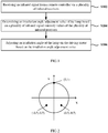
- Fig. 1 is a flowchart of an irradiation angle adjustment method of a lamp according to an embodiment of the present invention.
- the lamp comprises a plurality of infrared receivers and a driving motor.
- the irradiation angle adjustment method of the lamp at least comprises: step S102, receiving an infrared signal from a remote controller via the plurality of infrared receivers; Step S104, determining an irradiation angle adjustment value of the lamp based on a plurality of infrared signal intensity values of the plurality of infrared receivers; and Step S106, adjusting an irradiation angle of the lamp via the driving motor based on the irradiation angle adjustment value.
- the embodiment of the invention provides the irradiation angle adjustment scheme of the lamp.
- the lamp comprises the plurality of infrared sensors and the driving motor. Firstly, the infrared signal from the remote controller is received by the plurality of infrared receivers, then the irradiation angle adjustment value of the lamp is determined based on the plurality of infrared signal intensity values received by the plurality of infrared receivers, and then, based on the irradiation angle adjustment value, the irradiation angle of the lamp is adjusted by the driving motor.
- the technical scheme provided by the embodiment of the invention adjusts the irradiation angle of the lamp based on the plurality of infrared receivers and the driving motor, which can achieve better lighting effect, so as to meet the lighting needs of users in practical application. Further, when the irradiation angle of the lamp needs to be adjusted, the technical scheme provided by the embodiment of the invention controls the irradiation angle of the lamp only by operating the remote controller, so as to realize the intelligent adjustment of the irradiation angle of the lamp and achieve better irradiation effect.
- the installation position and the total number on the lamp can be selected according to actual requirements.
- the lamp comprises three infrared receivers, the three infrared receivers are installed on the extension of the plane where the lamp is located, and in the X-Y rectangular coordinate system established with the lamp as the origin, the coordinates of the three infrared receivers are normalized to be (0, 1), (- 0.5, - 0.5) and (0.5, - 0.5).
- three infrared receivers are installed on the extension of the plane where the lamp is located, and then the coordinates of the installation positions of the three infrared receivers are normalized to be (0, 1), (- 0.5, - 0.5) and (0.5, - 0.5) in the X-Y axis plane rectangular coordinate system established with the lamp as the coordinate origin on the plane where the lamp is located.
- the coordinates of the three infrared receivers are normalized to be (0,1), (- 0.5, - 0.5) and (0.5, - 0.5), that is, three points corresponding to the installation positions of the three infrared receivers are connected to form an isosceles triangle, and the vector sum of the three points on each of the X-axis and Y-axis is zero.
- a coordinate system easy for algorithm calculation is established, and then the coordinates of the three infrared receivers are normalized, so as to simplify the calculation process.
- the scheme provided by the preferred embodiment simplifies the calculation complexity to the greatest extent and improves the product response speed.
- a start button is arranged on the remote controller
- a Bluetooth communication module is arranged in each of the remote controller and the lamp
- the remote controller and the lamp interact with each other via the Bluetooth communication modules.
- the method further comprises: sending an irradiation angle adjustment start signal in response to pressing the start button of the remote controller; after receiving the start signal, the lamp turns on receiving the infrared signal.
- the irradiation angle adjustment value mentioned in step S104 described above preferably, the irradiation angle adjustment value comprises X-axis and Y-axis adjustment values.
- step S104 determines the irradiation angle adjustment value of the lamp based on the plurality of infrared signal intensity values of the plurality of infrared receivers.
- the embodiment of the invention provides an optional scheme in which the proportional superposition algorithm is carried out based on the infrared signal intensity values received by the three infrared receivers to determine the X-axis and Y-axis adjustment values respectively.
- the scheme provided by the embodiment of the invention directly carries out the proportional superposition algorithm for three infrared signal intensity values received by the three infrared receivers, so as to quickly determine the adjustment values of X-axis and Y-axis.
- the X-axis adjustment value an infrared signal intensity value 1 ⁇ 0 + an infrared signal intensity value 2 ⁇ (- 0.5) + an infrared signal intensity value 3 ⁇ 0.5;
- the Y-axis adjustment value the infrared signal intensity value 1 ⁇ 1 + the infrared signal intensity value 2 ⁇ (- 0.5) + the infrared signal intensity value 3 ⁇ (- 0.5).
- the infrared signal intensity values 1, 2 and 3 are the infrared signal intensity values received by three infrared receivers respectively.
- the proportional superposition algorithm is easy to calculate, the X-axis adjustment value and Y-axis adjustment value are easy to calculate, so as to improve the adjustment efficiency.
- the calculation of the Y-axis adjustment value is the same as the calculation of the X-axis adjustment value and will not be repeated here.
- the driving motor in step S106 comprises an X-axis direction rotating motor and a Y-axis direction rotating motor.
- the X-axis direction rotating motor and / or the Y-axis direction rotating motor it is preferable to drive the X-axis direction rotating motor and / or the Y-axis direction rotating motor to adjust the irradiation angle of the lamp based on the irradiation angle adjustment value. That is, in the embodiment of the invention, on the one hand, the X-axis direction rotating motor is driven independently, and then the irradiation angle of the lamp in the X-axis direction is adjusted; on the other hand, the Y-axis direction rotating motor is driven independently, so as to adjust the irradiation angle of the lamp in the Y-axis direction. In addition, the X-axis and Y-axis rotating motors are driven simultaneously to adjust the irradiation angle of the lamp. The scheme provided by the embodiment of the invention adjusts the irradiation angle of the lamp by driving the rotation of the motor.
- the X-axis direction rotating motor is controlled to rotate in the negative direction of the X-axis. If the X-axis adjustment value is positive, the X-axis direction rotating motor is controlled to rotate in the positive direction of the X-axis. If the Y-axis adjustment value is negative, the Y-axis direction rotating motor is controlled to rotate in the negative direction of the Y-axis. If the Y-axis adjustment value is positive, the Y-axis direction rotating motor is controlled to rotate in the X-axis positive direction.
- the irradiation angle adjustment method of the lamp further comprises: in the process of adjusting the irradiation angle of the lamp via the driving motor, updating the X-axis and Y-axis adjustment values in real time based on the infrared signal intensity values that are updated in real time until that the X-axis and Y-axis adjustment values are zero to stop adjusting the irradiation angle of the lamp via the driving motor.
- the infrared signal intensity values received by the infrared receivers also change, so that the X-axis and Y-axis adjustment values are updated, and the rotation direction of the motor is controlled in real time according to the updated X-axis and Y-axis adjustment values until that the X-axis and Y-axis adjustment values are zero, the rotation of the motor is stopped and the adjustment is completed.
- the X-axis and Y-axis adjustment values are updated in real time with the change of the irradiation angle of the lamp, so as to meet the real-time requirements.
- the irradiation angle adjustment method of the lamp further comprises: receiving an irradiation angle adjustment stop signal from the remote controller and stopping adjusting the irradiation angle of the lamp via the driving motor.
- the rotation of the driving motor is stopped, so as to stop the adjustment of the irradiation angle of the lamp.
- the scheme provided by the preferred embodiment can adjust the irradiation angle of the lamp according to the user's wishes to improve the user's experience of using the product.
- the embodiment of the invention further provides a lamp with adjustable irradiation angle.
- Fig. 3 is a structural block diagram of the lamp with adjustable irradiation angle according to an embodiment of the invention.
- the structural block diagram of the lamp with adjustable irradiation angle comprises at least: a plurality of infrared receivers 202 configured to receive an infrared signal from a remote controller and transmit a plurality of infrared signal intensity values of the infrared receivers to a processor; the processor 204 configured to determine an irradiation angle adjustment value of the lamp based on the plurality of infrared signal intensity values and transmit the irradiation angle adjustment value to a driving motor; and the driving motor 206 configured to adjust the irradiation angle of the lamp based on the irradiation angle adjustment value.
- the lamp comprises three infrared receivers, and the three infrared receivers are installed on the extension of the plane where the lamp is located, and the coordinates of the three infrared receivers are normalized to be (0, 1), (-0.5, -0.5) and (0.5, -0.5) in the X-Y rectangular coordinate established with the lamp as the origin.
- the irradiation angle adjustment value comprises X-axis and Y-axis adjustment values
- the processor 104 is further configured to perform a proportional superposition algorithm on the infrared signal intensity values received by the three infrared receivers to determine the X-axis and Y-axis adjustment values respectively.
- the X-axis adjustment value an infrared signal intensity value 1 ⁇ 0 + an infrared signal intensity value 2 ⁇ (-0.5) + an infrared signal intensity value 3 ⁇ 0.5;
- the Y-axis adjustment value the infrared signal intensity value 1 ⁇ 1 + the infrared signal intensity value 2 ⁇ (-0.5) + the infrared signal intensity value 3 ⁇ (-0.5);
- the infrared signal intensity values 1, 2 and 3 are the infrared signal intensity values received by the three infrared receivers respectively.
- the processor 204 in the process of adjusting the irradiation angle of the lamp via the driving motor 206, is further configured to update the X-axis and Y-axis adjustment values in real time based on the infrared signal intensity values that are updated in real time until the X-axis and Y-axis adjustment values are zero to stop adjusting the irradiation angle of the lamp via the driving motor.
- the processor 204 is further configured to stop the adjustment of the irradiation angle of the lamp via the driving motor after receiving an irradiation angle adjustment stop signal from the remote controller.
- the embodiment of the invention further provides an irradiation angle adjustment system of a lamp.
- the irradiation angle adjustment system of the lamp according to the embodiment of the present invention comprises at least a remote controller 300 and any lamp as described above, and the remote controller 300 is configured to transmit the infrared signal to the lamp.
- the remote controller 300 is further configured to be connected to the lamp in wireless communication; and the remote controller 300 is configured to send an irradiation angle adjustment start signal to the lamp and simultaneously transmit the infrared signal to the lamp; the lamp is configured to turn on the infrared receivers 202, the processor 204 and the driving motor 206 after receiving the start signal.
- the remote controller 300 is further configured to send an irradiation angle adjustment stop signal to the lamp and simultaneously turn off transmitting the infrared signal; the lamp is further configured to stop an operation of the infrared receiver 202, the processor 204 and the driving motor 206 after receiving the stop signal.
- the embodiment of the invention provides the irradiation angle adjustment scheme of the lamp.
- the lamp comprises the plurality of infrared sensors and the driving motor. Firstly, the infrared signal from the remote controller is received by the plurality of infrared receivers, then the irradiation angle adjustment value of the lamp is determined based on the plurality of infrared signal intensity values received by the plurality of infrared receivers, and then based on the irradiation angle adjustment value, the irradiation angle of the lamp is adjusted by the driving motor.
- the technical scheme provided by the embodiment of the invention adjusts the irradiation angle of the lamp based on the plurality of infrared receivers and the driving motor, and achieves better lighting effect, so as to meet the lighting needs of users in practical application. Further, when the irradiation angle of the lamp needs to be adjusted, the technical scheme provided by the embodiment of the invention controls the irradiation angle of the lamp only by operating the remote controller, so as to realize the intelligent adjustment of the irradiation angle of the lamp and achieve better irradiation effect.
Landscapes
- Engineering & Computer Science (AREA)
- Computer Networks & Wireless Communication (AREA)
- General Engineering & Computer Science (AREA)
- Physics & Mathematics (AREA)
- General Physics & Mathematics (AREA)
- Selective Calling Equipment (AREA)
- Circuit Arrangement For Electric Light Sources In General (AREA)
Abstract
Description
- The invention relates to the field of lighting technology, especially to an irradiation angle adjustment method and system of a lamp and a lamp with adjustable irradiation angle.
- With the rapid development of Internet of things and intelligent control technology, various intelligent products have sprung up. However, after the current lamps are installed, the irradiation angle of lamps is generally fixed, which cannot be adjusted according to requirements. The irradiation range of the lamps is small, for example, the guide rail spotlight is generally installed on the guide rail or directly installed on the ceiling or wall, and most of the guide rail spotlights can only irradiate in a fixed direction. In practical application, in order to make the irradiation effect of lamps better, the irradiation angle of lamps is needed to be adjusted according to specific conditions.
- In related technologies, when it is necessary to adjust the irradiation angle of the lamp, it is generally to adjust the irradiation angle of the lamp manually or by using tools, which cannot intelligently adjust the irradiation angle according to personal wishes and cannot meet the needs of users.
- The invention provides an irradiation angle adjustment method and system of a lamp and a lamp with adjustable irradiation angle to overcome the above problems or at least partially solve the above problems.
- According to one aspect of the present invention, there is provided an irradiation angle adjustment method of a lamp, the lamp comprises a plurality of infrared receivers and a driving motor, and the method comprises: receiving an infrared signal from a remote controller via the plurality of infrared receivers; determining an irradiation angle adjustment value of the lamp based on a plurality of infrared signal intensity values of the plurality of infrared receivers; and adjusting an irradiation angle of the lamp via the driving motor based on the irradiation angle adjustment value.
- Optionally, the lamp comprises three infrared receivers, the three infrared receivers are mounted on an extension of a plane where the lamp is located, and coordinates of the three infrared receivers are normalized to be (0, 1), (-0.5, -0.5) and (0.5, -0.5) in an X-Y rectangular coordinate that is established with the lamp as an origin.
- Optionally, the irradiation angle adjustment value comprises an X-axis adjustment value and a Y-axis adjustment value, and determining the irradiation angle adjustment value of the lamp based on the plurality of infrared signal intensity values of the plurality of infrared receivers comprises: performing a proportional superposition algorithm based on infrared signal intensity values respectively received by the three infrared receivers to determine the X-axis adjustment value and the Y-axis adjustment value.
- Optionally, the X-axis adjustment value = an infrared
signal intensity value 1 ∗ 0 + an infrared signal intensity value 2 ∗ (-0.5) + an infraredsignal intensity value 3 ∗ 0.5; the Y-axis adjustment value = the infraredsignal intensity value 1 ∗ 1 + the infrared signal intensity value 2 ∗ (- 0.5) + the infrared signal intensity value 3 ∗ (-0.5); where the infraredsignal intensity value 1, the infraredsignal intensity value 2 and the infraredsignal intensity value 3 are the infrared signal intensity values received by the three infrared receivers, respectively. - Optionally, the method described above further comprises: update the X-axis adjustment value and the Y-axis adjustment value in real time based on the infrared signal intensity values that are updated in real time, in a process of adjusting the irradiation angle of the lamp via the driving motor, until that the X-axis adjustment value and the Y-axis adjustment value are zero to stop adjusting the irradiation angle of the lamp via the driving motor.
- Optionally, the method described above further comprises: receiving an irradiation angle adjustment stop signal from the remote controller, and stopping adjusting the irradiation angle of the lamp via the driving motor.
- According to another aspect of the present invention, there is further provided a lamp with an adjustable irradiation angle, the lamp comprises a plurality of infrared receivers, a driving motor and a processor. The plurality of infrared receivers are configured to receive an infrared signal from a remote controller and transmit a plurality of infrared signal intensity values of the plurality of infrared receivers to the processor. The processor is configured to determine an irradiation angle adjustment value of the lamp based on the plurality of infrared signal intensity values, and transmit the irradiation angle adjustment value to the driving motor. The driving motor is configured to adjust an irradiation angle of the lamp based on the irradiation angle adjustment value.
- Optionally, the lamp comprises three infrared receivers, the three infrared receivers are mounted on an extension of a plane where the lamp is located, and coordinates of the three infrared receivers are normalized to be (0, 1), (-0.5, -0.5) and (0.5, -0.5) in an X-Y rectangular coordinate that is established with the lamp as an origin.
- Optionally, the irradiation angle adjustment value comprises an X-axis adjustment value and a Y-axis adjustment value, and the processor is further configured to perform a proportional superposition algorithm based on infrared signal intensity values respectively received by the three infrared receivers to determine the X-axis adjustment value and the Y-axis adjustment value.
- Optionally, the X-axis adjustment value = an infrared
signal intensity value 1 ∗ 0 + an infrared signal intensity value 2 ∗ (-0.5) + an infraredsignal intensity value 3 ∗ 0.5; the Y-axis adjustment value = the infraredsignal intensity value 1 ∗ 1 + the infrared signal intensity value 2 ∗ (-0.5) + the infrared signal intensity value 3 ∗ (-0.5); where the infraredsignal intensity value 1, the infraredsignal intensity value 2 and the infraredsignal intensity value 3 are the infrared signal intensity values received by the three infrared receivers respectively. - Optionally, the processor is further configured to, in a process of the driving motor adjusting the irradiation angle of the lamp, update the X-axis adjustment value and the Y-axis adjustment value in real time based on the infrared signal intensity values that are updated in real time until that the X-axis adjustment value and the Y-axis adjustment value are zero to stop adjusting the irradiation angle of the lamp via the driving motor.
- Optionally, the processor is further configured to stop adjusting the irradiation angle of the lamp via the driving motor after receiving an irradiation angle adjustment stop signal from the remote controller.
- According to another aspect of the present invention, there is further provided an irradiation angle adjustment system of a lamp comprising: a remote controller and the lamp according to any one as described above, in which the remote controller is configured to transmit the infrared signal to the lamp.
- Optionally, the remote controller is further configured to be connected with the lamp in wireless communication, and the remote controller is configured to send an irradiation angle adjustment start signal to the lamp and simultaneously transmit the infrared signal to the lamp; and the lamp is configured to turn on the plurality of infrared receivers, the processor and the driving motor after receiving the irradiation angle adjustment start signal.
- Optionally, the remote controller is further configured to send an irradiation angle adjustment stop signal to the lamp and simultaneously turn off transmitting the infrared signal; and the lamp is further configured to stop an operation of the plurality of infrared receivers, the processor and the driving motor after receiving the irradiation angle adjustment stop signal.
- The embodiments of the invention provide the irradiation angle adjustment scheme of the lamp. In the embodiments, the lamp comprises the plurality of infrared sensors and the driving motor. Firstly, the infrared signal from the remote controller is received by the plurality of infrared receivers, then the irradiation angle adjustment value of the lamp is determined based on the plurality of infrared signal intensity values received by a plurality of infrared receivers, and then based on the irradiation angle adjustment value, the irradiation angle of the lamp is adjusted by the driving motor. The technical scheme provided by the embodiments of the invention adjusts the irradiation angle of the lamp based on the plurality of infrared receivers and the driving motor, which can achieve better lighting effect, so as to meet the lighting needs of users in practical application. Further, when the irradiation angle of the lamp needs to be adjusted, the technical scheme provided by the embodiments of the invention controls the irradiation angle of the lamp only by operating the remote controller, so as to realize the intelligent adjustment of the irradiation angle of the lamp and achieve better irradiation effect.
- The above description is only an overview of the technical scheme of the invention. In order to better understand the technical means of the invention so that it can be implemented according to the contents of the description and in order to make the above and other objects, features and advantages of the invention more obvious and easy to be understood, the specific embodiments of the invention are given below.
- According to the following detailed description of specific embodiments of the invention in combination with the accompanying drawings, those skilled in the art will better understand the above and other objects, advantages and features of the invention.
- By reading the detailed description of the preferred embodiments below, various other advantages and benefits will become clear to those skilled in the art. The drawings are for the purpose of showing preferred embodiments only and are not considered to be a limitation of the present invention. Moreover, throughout the drawings, the same components are represented by the same reference symbols. In the drawings:
-
Fig. 1 is a flowchart of an irradiation angle adjustment method of a lamp according to an embodiment of the present invention; -
Fig. 2 is a schematic diagram of position coordinates of three infrared sensors according to a preferred embodiment of the present invention; -
Fig. 3 is a structural block diagram of the lamp with adjustable irradiation angle according to an embodiment of the present invention; -
Fig. 4 is a structural block diagram of the lamp with adjustable irradiation angle according to a preferred embodiment of the present invention; -
Fig. 5 is a block diagram of an irradiation angle adjustment system of the lamp according to an embodiment of the present invention. - Exemplary embodiments of the present disclosure will be described in more detail below with reference to the accompanying drawings. Although exemplary embodiments of the present disclosure are shown in the accompanying drawings, it should be understood that the present disclosure may be implemented in various forms and should not be limited by the embodiments set forth herein. On the contrary, these embodiments are provided to enable a more thorough understanding of the present disclosure and to fully convey the scope of the present disclosure to those skilled in the art.
- It should be noted that the features in the embodiments and preferred embodiments of the invention can be combined with each other without conflict.
-
Fig. 1 is a flowchart of an irradiation angle adjustment method of a lamp according to an embodiment of the present invention. In this embodiment, the lamp comprises a plurality of infrared receivers and a driving motor. - As shown in
Fig. 1 , the irradiation angle adjustment method of the lamp according to the embodiment of the present invention at least comprises: step S102, receiving an infrared signal from a remote controller via the plurality of infrared receivers; Step S104, determining an irradiation angle adjustment value of the lamp based on a plurality of infrared signal intensity values of the plurality of infrared receivers; and Step S106, adjusting an irradiation angle of the lamp via the driving motor based on the irradiation angle adjustment value. - The embodiment of the invention provides the irradiation angle adjustment scheme of the lamp. In the embodiment, the lamp comprises the plurality of infrared sensors and the driving motor. Firstly, the infrared signal from the remote controller is received by the plurality of infrared receivers, then the irradiation angle adjustment value of the lamp is determined based on the plurality of infrared signal intensity values received by the plurality of infrared receivers, and then, based on the irradiation angle adjustment value, the irradiation angle of the lamp is adjusted by the driving motor. The technical scheme provided by the embodiment of the invention adjusts the irradiation angle of the lamp based on the plurality of infrared receivers and the driving motor, which can achieve better lighting effect, so as to meet the lighting needs of users in practical application. Further, when the irradiation angle of the lamp needs to be adjusted, the technical scheme provided by the embodiment of the invention controls the irradiation angle of the lamp only by operating the remote controller, so as to realize the intelligent adjustment of the irradiation angle of the lamp and achieve better irradiation effect.
- For the plurality of infrared receivers in step S102 described above, the installation position and the total number on the lamp can be selected according to actual requirements. Referring to
Fig. 2 , in a preferred embodiment of the invention, the lamp comprises three infrared receivers, the three infrared receivers are installed on the extension of the plane where the lamp is located, and in the X-Y rectangular coordinate system established with the lamp as the origin, the coordinates of the three infrared receivers are normalized to be (0, 1), (- 0.5, - 0.5) and (0.5, - 0.5). In this preferred embodiment, three infrared receivers are installed on the extension of the plane where the lamp is located, and then the coordinates of the installation positions of the three infrared receivers are normalized to be (0, 1), (- 0.5, - 0.5) and (0.5, - 0.5) in the X-Y axis plane rectangular coordinate system established with the lamp as the coordinate origin on the plane where the lamp is located. Here, the coordinates of the three infrared receivers are normalized to be (0,1), (- 0.5, - 0.5) and (0.5, - 0.5), that is, three points corresponding to the installation positions of the three infrared receivers are connected to form an isosceles triangle, and the vector sum of the three points on each of the X-axis and Y-axis is zero. Based on the scheme provided by the preferred embodiment, a coordinate system easy for algorithm calculation is established, and then the coordinates of the three infrared receivers are normalized, so as to simplify the calculation process. The scheme provided by the preferred embodiment simplifies the calculation complexity to the greatest extent and improves the product response speed. - In an embodiment of the invention, a start button is arranged on the remote controller, a Bluetooth communication module is arranged in each of the remote controller and the lamp, and the remote controller and the lamp interact with each other via the Bluetooth communication modules. Before step S102 described above, the method further comprises: sending an irradiation angle adjustment start signal in response to pressing the start button of the remote controller; after receiving the start signal, the lamp turns on receiving the infrared signal.
- For the irradiation angle adjustment value mentioned in step S104 described above, preferably, the irradiation angle adjustment value comprises X-axis and Y-axis adjustment values.
- Furthermore, step S104 determines the irradiation angle adjustment value of the lamp based on the plurality of infrared signal intensity values of the plurality of infrared receivers. The embodiment of the invention provides an optional scheme in which the proportional superposition algorithm is carried out based on the infrared signal intensity values received by the three infrared receivers to determine the X-axis and Y-axis adjustment values respectively. The scheme provided by the embodiment of the invention directly carries out the proportional superposition algorithm for three infrared signal intensity values received by the three infrared receivers, so as to quickly determine the adjustment values of X-axis and Y-axis.
- For the above proportional superposition algorithm, in a preferred embodiment of the present invention: the X-axis adjustment value = an infrared
signal intensity value 1 ∗ 0 + an infrared signal intensity value 2 ∗ (- 0.5) + an infraredsignal intensity value 3 ∗ 0.5; the Y-axis adjustment value = the infraredsignal intensity value 1 ∗ 1 + the infrared signal intensity value 2 ∗ (- 0.5) + the infrared signal intensity value 3 ∗ (- 0.5). - In the preferred embodiment, the infrared signal intensity values 1, 2 and 3 are the infrared signal intensity values received by three infrared receivers respectively. In the scheme provided by the preferred embodiment, because the proportional superposition algorithm is easy to calculate, the X-axis adjustment value and Y-axis adjustment value are easy to calculate, so as to improve the adjustment efficiency.
- The proportional superposition algorithm here can be interpreted as superimposing the three infrared signal intensity values received by the three infrared receivers according to the normalized coordinates. In other words, it is to multiply the three infrared signal intensity values by their corresponding coordinate normalization coefficients and then add the multiplication results. For example, taking the case of calculating the X-axis adjustment value as an example, the three infrared signal intensity values are multiplied by their corresponding X-axis coordinate normalization coefficients, that is, the X-axis adjustment value = the infrared
signal intensity value 1 ∗ 0 + the infrared signal intensity value 2 ∗ (- 0.5) + the infraredsignal intensity value 3 ∗ 0.5. The calculation of the Y-axis adjustment value is the same as the calculation of the X-axis adjustment value and will not be repeated here. - In a preferred embodiment of the invention, the driving motor in step S106 comprises an X-axis direction rotating motor and a Y-axis direction rotating motor.
- Furthermore, for adjusting the irradiation angle of the lamp via the driving motor in step S106, it is preferable to drive the X-axis direction rotating motor and / or the Y-axis direction rotating motor to adjust the irradiation angle of the lamp based on the irradiation angle adjustment value. That is, in the embodiment of the invention, on the one hand, the X-axis direction rotating motor is driven independently, and then the irradiation angle of the lamp in the X-axis direction is adjusted; on the other hand, the Y-axis direction rotating motor is driven independently, so as to adjust the irradiation angle of the lamp in the Y-axis direction. In addition, the X-axis and Y-axis rotating motors are driven simultaneously to adjust the irradiation angle of the lamp. The scheme provided by the embodiment of the invention adjusts the irradiation angle of the lamp by driving the rotation of the motor.
- The specific adjustment process is described in combination with the proportional superposition algorithm described above. If the calculated X-axis adjustment value is negative, the X-axis direction rotating motor is controlled to rotate in the negative direction of the X-axis. If the X-axis adjustment value is positive, the X-axis direction rotating motor is controlled to rotate in the positive direction of the X-axis. If the Y-axis adjustment value is negative, the Y-axis direction rotating motor is controlled to rotate in the negative direction of the Y-axis. If the Y-axis adjustment value is positive, the Y-axis direction rotating motor is controlled to rotate in the X-axis positive direction.
- In order to meet the real-time requirements, in a preferred embodiment of the invention, the irradiation angle adjustment method of the lamp further comprises: in the process of adjusting the irradiation angle of the lamp via the driving motor, updating the X-axis and Y-axis adjustment values in real time based on the infrared signal intensity values that are updated in real time until that the X-axis and Y-axis adjustment values are zero to stop adjusting the irradiation angle of the lamp via the driving motor. In this embodiment, with the continuous change of the irradiation angle of the lamp, the infrared signal intensity values received by the infrared receivers also change, so that the X-axis and Y-axis adjustment values are updated, and the rotation direction of the motor is controlled in real time according to the updated X-axis and Y-axis adjustment values until that the X-axis and Y-axis adjustment values are zero, the rotation of the motor is stopped and the adjustment is completed. Based on the scheme provided by the preferred embodiment, the X-axis and Y-axis adjustment values are updated in real time with the change of the irradiation angle of the lamp, so as to meet the real-time requirements.
- In a preferred embodiment of the invention, the irradiation angle adjustment method of the lamp further comprises: receiving an irradiation angle adjustment stop signal from the remote controller and stopping adjusting the irradiation angle of the lamp via the driving motor. In the preferred embodiment, when the irradiation angle adjustment stop signal from the remote controller is received, the rotation of the driving motor is stopped, so as to stop the adjustment of the irradiation angle of the lamp. The scheme provided by the preferred embodiment can adjust the irradiation angle of the lamp according to the user's wishes to improve the user's experience of using the product.
- Based on the same inventive concept, the embodiment of the invention further provides a lamp with adjustable irradiation angle.
Fig. 3 is a structural block diagram of the lamp with adjustable irradiation angle according to an embodiment of the invention. - As shown in
Fig. 3 , the structural block diagram of the lamp with adjustable irradiation angle according to the embodiment of the present invention comprises at least: a plurality ofinfrared receivers 202 configured to receive an infrared signal from a remote controller and transmit a plurality of infrared signal intensity values of the infrared receivers to a processor; theprocessor 204 configured to determine an irradiation angle adjustment value of the lamp based on the plurality of infrared signal intensity values and transmit the irradiation angle adjustment value to a driving motor; and the drivingmotor 206 configured to adjust the irradiation angle of the lamp based on the irradiation angle adjustment value. - In a preferred embodiment, referring to
FIGS. 2 and4 , the lamp comprises three infrared receivers, and the three infrared receivers are installed on the extension of the plane where the lamp is located, and the coordinates of the three infrared receivers are normalized to be (0, 1), (-0.5, -0.5) and (0.5, -0.5) in the X-Y rectangular coordinate established with the lamp as the origin. - In a preferred embodiment, the irradiation angle adjustment value comprises X-axis and Y-axis adjustment values, and the processor 104 is further configured to perform a proportional superposition algorithm on the infrared signal intensity values received by the three infrared receivers to determine the X-axis and Y-axis adjustment values respectively.
- In a preferred embodiment, the X-axis adjustment value = an infrared
signal intensity value 1 ∗ 0 + an infrared signal intensity value 2 ∗ (-0.5) + an infraredsignal intensity value 3 ∗ 0.5; the Y-axis adjustment value = the infraredsignal intensity value 1 ∗ 1 + the infrared signal intensity value 2 ∗ (-0.5) + the infrared signal intensity value 3 ∗ (-0.5); the infrared signal intensity values 1, 2 and 3 are the infrared signal intensity values received by the three infrared receivers respectively. - In a preferred embodiment, in the process of adjusting the irradiation angle of the lamp via the driving
motor 206, theprocessor 204 is further configured to update the X-axis and Y-axis adjustment values in real time based on the infrared signal intensity values that are updated in real time until the X-axis and Y-axis adjustment values are zero to stop adjusting the irradiation angle of the lamp via the driving motor. - In a preferred embodiment, the
processor 204 is further configured to stop the adjustment of the irradiation angle of the lamp via the driving motor after receiving an irradiation angle adjustment stop signal from the remote controller. - Based on the same inventive concept, the embodiment of the invention further provides an irradiation angle adjustment system of a lamp. As shown in
Fig. 5 , the irradiation angle adjustment system of the lamp according to the embodiment of the present invention comprises at least aremote controller 300 and any lamp as described above, and theremote controller 300 is configured to transmit the infrared signal to the lamp. - In a preferred embodiment, the
remote controller 300 is further configured to be connected to the lamp in wireless communication; and theremote controller 300 is configured to send an irradiation angle adjustment start signal to the lamp and simultaneously transmit the infrared signal to the lamp; the lamp is configured to turn on theinfrared receivers 202, theprocessor 204 and the drivingmotor 206 after receiving the start signal. - In a preferred embodiment, the
remote controller 300 is further configured to send an irradiation angle adjustment stop signal to the lamp and simultaneously turn off transmitting the infrared signal; the lamp is further configured to stop an operation of theinfrared receiver 202, theprocessor 204 and the drivingmotor 206 after receiving the stop signal. - The embodiment of the invention provides the irradiation angle adjustment scheme of the lamp. In the embodiment, the lamp comprises the plurality of infrared sensors and the driving motor. Firstly, the infrared signal from the remote controller is received by the plurality of infrared receivers, then the irradiation angle adjustment value of the lamp is determined based on the plurality of infrared signal intensity values received by the plurality of infrared receivers, and then based on the irradiation angle adjustment value, the irradiation angle of the lamp is adjusted by the driving motor. The technical scheme provided by the embodiment of the invention adjusts the irradiation angle of the lamp based on the plurality of infrared receivers and the driving motor, and achieves better lighting effect, so as to meet the lighting needs of users in practical application. Further, when the irradiation angle of the lamp needs to be adjusted, the technical scheme provided by the embodiment of the invention controls the irradiation angle of the lamp only by operating the remote controller, so as to realize the intelligent adjustment of the irradiation angle of the lamp and achieve better irradiation effect.
- At this point, those skilled in the art should recognize that although a plurality of exemplary embodiments of the invention have been shown and described in detail herein, many other variants or modifications in accordance with the principles of the invention can be directly determined or derived according to the contents of the disclosure of the invention without departing from the spirit and scope of the invention. Therefore, the scope of the invention should be understood and recognized as covering all these other variants or modifications.
Claims (15)
- An irradiation angle adjustment method of a lamp, the lamp comprising a plurality of infrared receivers and a driving motor, the method comprising:receiving an infrared signal from a remote controller via the plurality of infrared receivers;determining an irradiation angle adjustment value of the lamp based on a plurality of infrared signal intensity values of the plurality of infrared receivers; andadjusting an irradiation angle of the lamp via the driving motor based on the irradiation angle adjustment value.
- The irradiation angle adjustment method according to claim 1, wherein the lamp comprises three infrared receivers, the three infrared receivers are mounted on an extension of a plane where the lamp is located, and coordinates of the three infrared receivers are normalized to be (0, 1), (-0.5, -0.5) and (0.5, -0.5) in an X-Y rectangular coordinate that is established with the lamp as an origin.
- The irradiation angle adjustment method according to claim 2, wherein the irradiation angle adjustment value comprises an X-axis adjustment value and a Y-axis adjustment value, and determining the irradiation angle adjustment value of the lamp based on the plurality of infrared signal intensity values of the plurality of infrared receivers comprises:
performing a proportional superposition algorithm based on infrared signal intensity values respectively received by the three infrared receivers to determine the X-axis adjustment value and the Y-axis adjustment value. - The irradiation angle adjustment method according to claim 3, wherein


- The irradiation angle adjustment method according to claim 3 or 4, further comprising:
updating the X-axis adjustment value and the Y-axis adjustment value in real time based on the infrared signal intensity values that are updated in real time, in a process of adjusting the irradiation angle of the lamp via the driving motor, until that the X-axis adjustment value and the Y-axis adjustment value are zero to stop adjusting the irradiation angle of the lamp via the driving motor. - The irradiation angle adjustment method according to any one of claims 1-5, further comprising:
receiving an irradiation angle adjustment stop signal from the remote controller, and stopping adjusting the irradiation angle of the lamp via the driving motor. - A lamp with an adjustable irradiation angle, the lamp comprising a plurality of infrared receivers, a driving motor and a processor, whereinthe plurality of infrared receivers are configured to receive an infrared signal from a remote controller and transmit a plurality of infrared signal intensity values of the plurality of infrared receivers to the processor;the processor is configured to determine an irradiation angle adjustment value of the lamp based on the plurality of infrared signal intensity values, and transmit the irradiation angle adjustment value to the driving motor; andthe driving motor is configured to adjust an irradiation angle of the lamp based on the irradiation angle adjustment value.
- The lamp according to claim 7, wherein the lamp comprises three infrared receivers, the three infrared receivers are mounted on an extension of a plane where the lamp is located, and coordinates of the three infrared receivers are normalized to be (0, 1), (-0.5, -0.5) and (0.5, -0.5) in an X-Y rectangular coordinate that is established with the lamp as an origin.
- The lamp according to claim 8, wherein the irradiation angle adjustment value comprises an X-axis adjustment value and a Y-axis adjustment value,
the processor is further configured to perform a proportional superposition algorithm based on infrared signal intensity values respectively received by the three infrared receivers to determine the X-axis adjustment value and the Y-axis adjustment value. - The lamp according to claim 9, wherein


- The lamp according to claim 9 or 10, wherein the processor is further configured to, in a process of the driving motor adjusting the irradiation angle of the lamp, update the X-axis adjustment value and the Y-axis adjustment value in real time based on the infrared signal intensity values that are updated in real time until that the X-axis adjustment value and the Y-axis adjustment value are zero to stop adjusting the irradiation angle of the lamp via the driving motor.
- The lamp according to any one of claims 7-10, wherein the processor is further configured to stop adjusting the irradiation angle of the lamp via the driving motor after receiving an irradiation angle adjustment stop signal from the remote controller.
- An irradiation angle adjustment system of a lamp comprising:
a remote controller and the lamp according to any one of claims 7-12, wherein the remote controller is configured to transmit the infrared signal to the lamp. - The irradiation angle adjustment system according to claim 13, whereinthe remote controller is further configured to be connected with the lamp in wireless communication, and the remote controller is configured to send an irradiation angle adjustment start signal to the lamp and simultaneously transmit the infrared signal to the lamp; andthe lamp is configured to turn on the plurality of infrared receivers, the processor and the driving motor after receiving the irradiation angle adjustment start signal.
- The irradiation angle adjustment system according to claim 13 or 14, whereinthe remote controller is further configured to send an irradiation angle adjustment stop signal to the lamp and simultaneously turn off transmitting the infrared signal; andthe lamp is further configured to stop an operation of the plurality of infrared receivers, the processor and the driving motor after receiving the irradiation angle adjustment stop signal.
Applications Claiming Priority (3)
| Application Number | Priority Date | Filing Date | Title |
|---|---|---|---|
| CN201920138528.3U CN210641116U (en) | 2019-01-25 | 2019-01-25 | Lamps with adjustable illumination angles and illumination angle adjustment systems for lamps |
| CN201910074698.4A CN109640493A (en) | 2019-01-25 | 2019-01-25 | The lamps and lanterns of the irradiating angle adjusting methods of lamps and lanterns, system and adjusting irradiation angle |
| PCT/CN2019/130138 WO2020151462A1 (en) | 2019-01-25 | 2019-12-30 | Method and system for adjusting beam angle of lamp, and lamp having adjustable beam angle |
Publications (3)
| Publication Number | Publication Date |
|---|---|
| EP3911122A1 true EP3911122A1 (en) | 2021-11-17 |
| EP3911122A4 EP3911122A4 (en) | 2022-02-23 |
| EP3911122B1 EP3911122B1 (en) | 2024-03-20 |
Family
ID=71736122
Family Applications (1)
| Application Number | Title | Priority Date | Filing Date |
|---|---|---|---|
| EP19910946.3A Active EP3911122B1 (en) | 2019-01-25 | 2019-12-30 | Method and system for adjusting beam angle of lamp, and lamp having adjustable beam angle |
Country Status (3)
| Country | Link |
|---|---|
| US (1) | US11968760B2 (en) |
| EP (1) | EP3911122B1 (en) |
| WO (1) | WO2020151462A1 (en) |
Family Cites Families (11)
| Publication number | Priority date | Publication date | Assignee | Title |
|---|---|---|---|---|
| US9955551B2 (en) * | 2002-07-12 | 2018-04-24 | Yechezkal Evan Spero | Detector controlled illuminating system |
| DE60316178T2 (en) * | 2002-10-24 | 2008-06-05 | Nakagawa Laboratories, Inc. | COMMUNICATION DEVICE WITH ILLUMINATING LIGHT |
| EP1839014A2 (en) * | 2005-01-12 | 2007-10-03 | Koninklijke Philips Electronics N.V. | Spotlight unit comprising means for adjusting the light beam direction |
| JP5236003B2 (en) * | 2007-11-08 | 2013-07-17 | 建興電子科技股▲ふん▼有限公司 | Lighting system |
| US7866848B2 (en) * | 2008-07-07 | 2011-01-11 | Edison Opto Corporation | Illumination system capable of automatically adjusting illumination direction according to human body's signal |
| US20150308642A1 (en) * | 2014-04-23 | 2015-10-29 | General Led, Inc. | Self-Aiming Track Light Fixture System and Method |
| CN106482005A (en) * | 2015-08-25 | 2017-03-08 | 上海本星电子科技有限公司 | Integral remote-controlled lamp and its cone-shaped beam remote control |
| CN205014298U (en) * | 2015-10-20 | 2016-02-03 | 广州力铭光电科技有限公司 | LED meeting lamp shines angel position control system |
| CN206918814U (en) * | 2017-07-14 | 2018-01-23 | 四川溯源科技有限公司 | A kind of light fixture of adjusting irradiation angle |
| US11184967B2 (en) * | 2018-05-07 | 2021-11-23 | Zane Coleman | Angularly varying light emitting device with an imager |
| CN109640493A (en) * | 2019-01-25 | 2019-04-16 | 欧普照明股份有限公司 | The lamps and lanterns of the irradiating angle adjusting methods of lamps and lanterns, system and adjusting irradiation angle |
-
2019
- 2019-12-30 WO PCT/CN2019/130138 patent/WO2020151462A1/en not_active Ceased
- 2019-12-30 EP EP19910946.3A patent/EP3911122B1/en active Active
-
2021
- 2021-08-13 US US17/402,266 patent/US11968760B2/en active Active
Also Published As
| Publication number | Publication date |
|---|---|
| US11968760B2 (en) | 2024-04-23 |
| WO2020151462A1 (en) | 2020-07-30 |
| EP3911122A4 (en) | 2022-02-23 |
| EP3911122B1 (en) | 2024-03-20 |
| US20210378075A1 (en) | 2021-12-02 |
Similar Documents
| Publication | Publication Date | Title |
|---|---|---|
| CN108161889B (en) | Industrial robot based on AGV | |
| CN108226862B (en) | Portable device, beacon and navigation system | |
| EP3196726A3 (en) | Apparatus and system for remotely controlling a moving robot and method thereof | |
| CN205384727U (en) | Remote controller, movable platform , movable platform system and unmanned vehicles | |
| JP2013250005A (en) | Self-propelled electronic apparatus | |
| CN105303807A (en) | Remote controller, movable platform, control method and system of platform, and unmanned aerial vehicle | |
| CN108650763A (en) | Method, device and equipment for adjusting brightness of light emitting part of vehicle-mounted intelligent controller | |
| EP3816005A3 (en) | Adaptive speed control system | |
| JP2017176116A (en) | Control device for autonomous vehicle | |
| CA2489159A1 (en) | Light controlled movable toy | |
| CN107891815A (en) | The method and apparatus of intelligent back vision mirror LED brightness Multistage Control | |
| JPH0971386A (en) | Remote control device | |
| EP3911122B1 (en) | Method and system for adjusting beam angle of lamp, and lamp having adjustable beam angle | |
| CN106293042A (en) | A kind of information processing method and electronic equipment | |
| CA2548688A1 (en) | Inductively coupled plasma alignment apparatus and method | |
| KR20160051360A (en) | Gesture recognition apparatus for vehicle | |
| CN109640493A (en) | The lamps and lanterns of the irradiating angle adjusting methods of lamps and lanterns, system and adjusting irradiation angle | |
| WO2020031864A1 (en) | Control terminal | |
| CN210641116U (en) | Lamps with adjustable illumination angles and illumination angle adjustment systems for lamps | |
| EP1211012A3 (en) | Apparatus and method for welding a hermetic compressor | |
| KR20130092851A (en) | Tilting control device of antenna | |
| CN105491756A (en) | Led light adjusting method | |
| JP2005238885A (en) | In-vehicle display device | |
| JPH10582A (en) | Robot controller | |
| JPH06260005A (en) | Device for controlling irradiation direction of spotlight |
Legal Events
| Date | Code | Title | Description |
|---|---|---|---|
| STAA | Information on the status of an ep patent application or granted ep patent |
Free format text: STATUS: THE INTERNATIONAL PUBLICATION HAS BEEN MADE |
|
| PUAI | Public reference made under article 153(3) epc to a published international application that has entered the european phase |
Free format text: ORIGINAL CODE: 0009012 |
|
| STAA | Information on the status of an ep patent application or granted ep patent |
Free format text: STATUS: REQUEST FOR EXAMINATION WAS MADE |
|
| 17P | Request for examination filed |
Effective date: 20210809 |
|
| AK | Designated contracting states |
Kind code of ref document: A1 Designated state(s): AL AT BE BG CH CY CZ DE DK EE ES FI FR GB GR HR HU IE IS IT LI LT LU LV MC MK MT NL NO PL PT RO RS SE SI SK SM TR |
|
| A4 | Supplementary search report drawn up and despatched |
Effective date: 20220126 |
|
| RIC1 | Information provided on ipc code assigned before grant |
Ipc: F21V 21/15 20060101ALN20220120BHEP Ipc: H05B 47/13 20200101ALI20220120BHEP Ipc: H05B 47/195 20200101AFI20220120BHEP |
|
| DAV | Request for validation of the european patent (deleted) | ||
| DAX | Request for extension of the european patent (deleted) | ||
| REG | Reference to a national code |
Ref country code: DE Ref legal event code: R079 Free format text: PREVIOUS MAIN CLASS: H05B0039040000 Ipc: H05B0047195000 Ref country code: DE Ref legal event code: R079 Ref document number: 602019048825 Country of ref document: DE Free format text: PREVIOUS MAIN CLASS: H05B0039040000 Ipc: H05B0047195000 |
|
| RIC1 | Information provided on ipc code assigned before grant |
Ipc: F21V 21/15 20060101ALN20230530BHEP Ipc: G08C 23/04 20060101ALI20230530BHEP Ipc: H05B 47/13 20200101ALI20230530BHEP Ipc: H05B 47/195 20200101AFI20230530BHEP |
|
| RIC1 | Information provided on ipc code assigned before grant |
Ipc: F21V 21/15 20060101ALN20230615BHEP Ipc: G08C 23/04 20060101ALI20230615BHEP Ipc: H05B 47/13 20200101ALI20230615BHEP Ipc: H05B 47/195 20200101AFI20230615BHEP |
|
| GRAP | Despatch of communication of intention to grant a patent |
Free format text: ORIGINAL CODE: EPIDOSNIGR1 |
|
| STAA | Information on the status of an ep patent application or granted ep patent |
Free format text: STATUS: GRANT OF PATENT IS INTENDED |
|
| INTG | Intention to grant announced |
Effective date: 20231005 |
|
| GRAS | Grant fee paid |
Free format text: ORIGINAL CODE: EPIDOSNIGR3 |
|
| GRAA | (expected) grant |
Free format text: ORIGINAL CODE: 0009210 |
|
| STAA | Information on the status of an ep patent application or granted ep patent |
Free format text: STATUS: THE PATENT HAS BEEN GRANTED |
|
| AK | Designated contracting states |
Kind code of ref document: B1 Designated state(s): AL AT BE BG CH CY CZ DE DK EE ES FI FR GB GR HR HU IE IS IT LI LT LU LV MC MK MT NL NO PL PT RO RS SE SI SK SM TR |
|
| REG | Reference to a national code |
Ref country code: GB Ref legal event code: FG4D |
|
| REG | Reference to a national code |
Ref country code: CH Ref legal event code: EP |
|
| REG | Reference to a national code |
Ref country code: IE Ref legal event code: FG4D |
|
| REG | Reference to a national code |
Ref country code: DE Ref legal event code: R096 Ref document number: 602019048825 Country of ref document: DE |
|
| PG25 | Lapsed in a contracting state [announced via postgrant information from national office to epo] |
Ref country code: LT Free format text: LAPSE BECAUSE OF FAILURE TO SUBMIT A TRANSLATION OF THE DESCRIPTION OR TO PAY THE FEE WITHIN THE PRESCRIBED TIME-LIMIT Effective date: 20240320 |
|
| REG | Reference to a national code |
Ref country code: NL Ref legal event code: FP Ref country code: LT Ref legal event code: MG9D |
|
| PG25 | Lapsed in a contracting state [announced via postgrant information from national office to epo] |
Ref country code: GR Free format text: LAPSE BECAUSE OF FAILURE TO SUBMIT A TRANSLATION OF THE DESCRIPTION OR TO PAY THE FEE WITHIN THE PRESCRIBED TIME-LIMIT Effective date: 20240621 |
|
| PG25 | Lapsed in a contracting state [announced via postgrant information from national office to epo] |
Ref country code: RS Free format text: LAPSE BECAUSE OF FAILURE TO SUBMIT A TRANSLATION OF THE DESCRIPTION OR TO PAY THE FEE WITHIN THE PRESCRIBED TIME-LIMIT Effective date: 20240620 Ref country code: HR Free format text: LAPSE BECAUSE OF FAILURE TO SUBMIT A TRANSLATION OF THE DESCRIPTION OR TO PAY THE FEE WITHIN THE PRESCRIBED TIME-LIMIT Effective date: 20240320 |
|
| PG25 | Lapsed in a contracting state [announced via postgrant information from national office to epo] |
Ref country code: RS Free format text: LAPSE BECAUSE OF FAILURE TO SUBMIT A TRANSLATION OF THE DESCRIPTION OR TO PAY THE FEE WITHIN THE PRESCRIBED TIME-LIMIT Effective date: 20240620 Ref country code: NO Free format text: LAPSE BECAUSE OF FAILURE TO SUBMIT A TRANSLATION OF THE DESCRIPTION OR TO PAY THE FEE WITHIN THE PRESCRIBED TIME-LIMIT Effective date: 20240620 Ref country code: LT Free format text: LAPSE BECAUSE OF FAILURE TO SUBMIT A TRANSLATION OF THE DESCRIPTION OR TO PAY THE FEE WITHIN THE PRESCRIBED TIME-LIMIT Effective date: 20240320 Ref country code: HR Free format text: LAPSE BECAUSE OF FAILURE TO SUBMIT A TRANSLATION OF THE DESCRIPTION OR TO PAY THE FEE WITHIN THE PRESCRIBED TIME-LIMIT Effective date: 20240320 Ref country code: GR Free format text: LAPSE BECAUSE OF FAILURE TO SUBMIT A TRANSLATION OF THE DESCRIPTION OR TO PAY THE FEE WITHIN THE PRESCRIBED TIME-LIMIT Effective date: 20240621 Ref country code: FI Free format text: LAPSE BECAUSE OF FAILURE TO SUBMIT A TRANSLATION OF THE DESCRIPTION OR TO PAY THE FEE WITHIN THE PRESCRIBED TIME-LIMIT Effective date: 20240320 Ref country code: BG Free format text: LAPSE BECAUSE OF FAILURE TO SUBMIT A TRANSLATION OF THE DESCRIPTION OR TO PAY THE FEE WITHIN THE PRESCRIBED TIME-LIMIT Effective date: 20240320 |
|
| REG | Reference to a national code |
Ref country code: AT Ref legal event code: MK05 Ref document number: 1668952 Country of ref document: AT Kind code of ref document: T Effective date: 20240320 |
|
| PG25 | Lapsed in a contracting state [announced via postgrant information from national office to epo] |
Ref country code: SE Free format text: LAPSE BECAUSE OF FAILURE TO SUBMIT A TRANSLATION OF THE DESCRIPTION OR TO PAY THE FEE WITHIN THE PRESCRIBED TIME-LIMIT Effective date: 20240320 Ref country code: LV Free format text: LAPSE BECAUSE OF FAILURE TO SUBMIT A TRANSLATION OF THE DESCRIPTION OR TO PAY THE FEE WITHIN THE PRESCRIBED TIME-LIMIT Effective date: 20240320 |
|
| PG25 | Lapsed in a contracting state [announced via postgrant information from national office to epo] |
Ref country code: IS Free format text: LAPSE BECAUSE OF FAILURE TO SUBMIT A TRANSLATION OF THE DESCRIPTION OR TO PAY THE FEE WITHIN THE PRESCRIBED TIME-LIMIT Effective date: 20240720 |
|
| PG25 | Lapsed in a contracting state [announced via postgrant information from national office to epo] |
Ref country code: SM Free format text: LAPSE BECAUSE OF FAILURE TO SUBMIT A TRANSLATION OF THE DESCRIPTION OR TO PAY THE FEE WITHIN THE PRESCRIBED TIME-LIMIT Effective date: 20240320 Ref country code: PT Free format text: LAPSE BECAUSE OF FAILURE TO SUBMIT A TRANSLATION OF THE DESCRIPTION OR TO PAY THE FEE WITHIN THE PRESCRIBED TIME-LIMIT Effective date: 20240722 |
|
| PG25 | Lapsed in a contracting state [announced via postgrant information from national office to epo] |
Ref country code: ES Free format text: LAPSE BECAUSE OF FAILURE TO SUBMIT A TRANSLATION OF THE DESCRIPTION OR TO PAY THE FEE WITHIN THE PRESCRIBED TIME-LIMIT Effective date: 20240320 |
|
| PG25 | Lapsed in a contracting state [announced via postgrant information from national office to epo] |
Ref country code: CZ Free format text: LAPSE BECAUSE OF FAILURE TO SUBMIT A TRANSLATION OF THE DESCRIPTION OR TO PAY THE FEE WITHIN THE PRESCRIBED TIME-LIMIT Effective date: 20240320 Ref country code: EE Free format text: LAPSE BECAUSE OF FAILURE TO SUBMIT A TRANSLATION OF THE DESCRIPTION OR TO PAY THE FEE WITHIN THE PRESCRIBED TIME-LIMIT Effective date: 20240320 |
|
| PG25 | Lapsed in a contracting state [announced via postgrant information from national office to epo] |
Ref country code: AT Free format text: LAPSE BECAUSE OF FAILURE TO SUBMIT A TRANSLATION OF THE DESCRIPTION OR TO PAY THE FEE WITHIN THE PRESCRIBED TIME-LIMIT Effective date: 20240320 |
|
| PG25 | Lapsed in a contracting state [announced via postgrant information from national office to epo] |
Ref country code: PL Free format text: LAPSE BECAUSE OF FAILURE TO SUBMIT A TRANSLATION OF THE DESCRIPTION OR TO PAY THE FEE WITHIN THE PRESCRIBED TIME-LIMIT Effective date: 20240320 |
|
| PG25 | Lapsed in a contracting state [announced via postgrant information from national office to epo] |
Ref country code: SK Free format text: LAPSE BECAUSE OF FAILURE TO SUBMIT A TRANSLATION OF THE DESCRIPTION OR TO PAY THE FEE WITHIN THE PRESCRIBED TIME-LIMIT Effective date: 20240320 |
|
| PG25 | Lapsed in a contracting state [announced via postgrant information from national office to epo] |
Ref country code: SM Free format text: LAPSE BECAUSE OF FAILURE TO SUBMIT A TRANSLATION OF THE DESCRIPTION OR TO PAY THE FEE WITHIN THE PRESCRIBED TIME-LIMIT Effective date: 20240320 Ref country code: SK Free format text: LAPSE BECAUSE OF FAILURE TO SUBMIT A TRANSLATION OF THE DESCRIPTION OR TO PAY THE FEE WITHIN THE PRESCRIBED TIME-LIMIT Effective date: 20240320 Ref country code: RO Free format text: LAPSE BECAUSE OF FAILURE TO SUBMIT A TRANSLATION OF THE DESCRIPTION OR TO PAY THE FEE WITHIN THE PRESCRIBED TIME-LIMIT Effective date: 20240320 Ref country code: PT Free format text: LAPSE BECAUSE OF FAILURE TO SUBMIT A TRANSLATION OF THE DESCRIPTION OR TO PAY THE FEE WITHIN THE PRESCRIBED TIME-LIMIT Effective date: 20240722 Ref country code: PL Free format text: LAPSE BECAUSE OF FAILURE TO SUBMIT A TRANSLATION OF THE DESCRIPTION OR TO PAY THE FEE WITHIN THE PRESCRIBED TIME-LIMIT Effective date: 20240320 Ref country code: IS Free format text: LAPSE BECAUSE OF FAILURE TO SUBMIT A TRANSLATION OF THE DESCRIPTION OR TO PAY THE FEE WITHIN THE PRESCRIBED TIME-LIMIT Effective date: 20240720 Ref country code: ES Free format text: LAPSE BECAUSE OF FAILURE TO SUBMIT A TRANSLATION OF THE DESCRIPTION OR TO PAY THE FEE WITHIN THE PRESCRIBED TIME-LIMIT Effective date: 20240320 Ref country code: EE Free format text: LAPSE BECAUSE OF FAILURE TO SUBMIT A TRANSLATION OF THE DESCRIPTION OR TO PAY THE FEE WITHIN THE PRESCRIBED TIME-LIMIT Effective date: 20240320 Ref country code: CZ Free format text: LAPSE BECAUSE OF FAILURE TO SUBMIT A TRANSLATION OF THE DESCRIPTION OR TO PAY THE FEE WITHIN THE PRESCRIBED TIME-LIMIT Effective date: 20240320 Ref country code: AT Free format text: LAPSE BECAUSE OF FAILURE TO SUBMIT A TRANSLATION OF THE DESCRIPTION OR TO PAY THE FEE WITHIN THE PRESCRIBED TIME-LIMIT Effective date: 20240320 |
|
| PG25 | Lapsed in a contracting state [announced via postgrant information from national office to epo] |
Ref country code: IT Free format text: LAPSE BECAUSE OF FAILURE TO SUBMIT A TRANSLATION OF THE DESCRIPTION OR TO PAY THE FEE WITHIN THE PRESCRIBED TIME-LIMIT Effective date: 20240320 |
|
| REG | Reference to a national code |
Ref country code: DE Ref legal event code: R097 Ref document number: 602019048825 Country of ref document: DE |
|
| PG25 | Lapsed in a contracting state [announced via postgrant information from national office to epo] |
Ref country code: IT Free format text: LAPSE BECAUSE OF FAILURE TO SUBMIT A TRANSLATION OF THE DESCRIPTION OR TO PAY THE FEE WITHIN THE PRESCRIBED TIME-LIMIT Effective date: 20240320 |
|
| PG25 | Lapsed in a contracting state [announced via postgrant information from national office to epo] |
Ref country code: DK Free format text: LAPSE BECAUSE OF FAILURE TO SUBMIT A TRANSLATION OF THE DESCRIPTION OR TO PAY THE FEE WITHIN THE PRESCRIBED TIME-LIMIT Effective date: 20240320 |
|
| PGFP | Annual fee paid to national office [announced via postgrant information from national office to epo] |
Ref country code: BE Payment date: 20241220 Year of fee payment: 6 |
|
| PGFP | Annual fee paid to national office [announced via postgrant information from national office to epo] |
Ref country code: FR Payment date: 20241224 Year of fee payment: 6 |
|
| PLBE | No opposition filed within time limit |
Free format text: ORIGINAL CODE: 0009261 |
|
| STAA | Information on the status of an ep patent application or granted ep patent |
Free format text: STATUS: NO OPPOSITION FILED WITHIN TIME LIMIT |
|
| PG25 | Lapsed in a contracting state [announced via postgrant information from national office to epo] |
Ref country code: DK Free format text: LAPSE BECAUSE OF FAILURE TO SUBMIT A TRANSLATION OF THE DESCRIPTION OR TO PAY THE FEE WITHIN THE PRESCRIBED TIME-LIMIT Effective date: 20240320 |
|
| 26N | No opposition filed |
Effective date: 20241223 |
|
| PG25 | Lapsed in a contracting state [announced via postgrant information from national office to epo] |
Ref country code: SI Free format text: LAPSE BECAUSE OF FAILURE TO SUBMIT A TRANSLATION OF THE DESCRIPTION OR TO PAY THE FEE WITHIN THE PRESCRIBED TIME-LIMIT Effective date: 20240320 |
|
| PG25 | Lapsed in a contracting state [announced via postgrant information from national office to epo] |
Ref country code: MC Free format text: LAPSE BECAUSE OF FAILURE TO SUBMIT A TRANSLATION OF THE DESCRIPTION OR TO PAY THE FEE WITHIN THE PRESCRIBED TIME-LIMIT Effective date: 20240320 |
|
| REG | Reference to a national code |
Ref country code: CH Ref legal event code: PL |
|
| PG25 | Lapsed in a contracting state [announced via postgrant information from national office to epo] |
Ref country code: LU Free format text: LAPSE BECAUSE OF NON-PAYMENT OF DUE FEES Effective date: 20241230 |
|
| PG25 | Lapsed in a contracting state [announced via postgrant information from national office to epo] |
Ref country code: CH Free format text: LAPSE BECAUSE OF NON-PAYMENT OF DUE FEES Effective date: 20241231 |
|
| PG25 | Lapsed in a contracting state [announced via postgrant information from national office to epo] |
Ref country code: IE Free format text: LAPSE BECAUSE OF NON-PAYMENT OF DUE FEES Effective date: 20241230 |
|
| PGFP | Annual fee paid to national office [announced via postgrant information from national office to epo] |
Ref country code: NL Payment date: 20251127 Year of fee payment: 7 |
|
| PGFP | Annual fee paid to national office [announced via postgrant information from national office to epo] |
Ref country code: GB Payment date: 20251229 Year of fee payment: 7 |
|
| PGFP | Annual fee paid to national office [announced via postgrant information from national office to epo] |
Ref country code: DE Payment date: 20251231 Year of fee payment: 7 |