EP3910662B1 - Magnetronanordnung - Google Patents
Magnetronanordnung Download PDFInfo
- Publication number
- EP3910662B1 EP3910662B1 EP21163946.3A EP21163946A EP3910662B1 EP 3910662 B1 EP3910662 B1 EP 3910662B1 EP 21163946 A EP21163946 A EP 21163946A EP 3910662 B1 EP3910662 B1 EP 3910662B1
- Authority
- EP
- European Patent Office
- Prior art keywords
- actuator
- target
- magnet system
- magnetron assembly
- generator
- Prior art date
- Legal status (The legal status is an assumption and is not a legal conclusion. Google has not performed a legal analysis and makes no representation as to the accuracy of the status listed.)
- Active
Links
Images




Classifications
-
- H—ELECTRICITY
- H01—ELECTRIC ELEMENTS
- H01J—ELECTRIC DISCHARGE TUBES OR DISCHARGE LAMPS
- H01J37/00—Discharge tubes with provision for introducing objects or material to be exposed to the discharge, e.g. for the purpose of examination or processing thereof
- H01J37/32—Gas-filled discharge tubes
- H01J37/34—Gas-filled discharge tubes operating with cathodic sputtering
- H01J37/3402—Gas-filled discharge tubes operating with cathodic sputtering using supplementary magnetic fields
- H01J37/3405—Magnetron sputtering
-
- C—CHEMISTRY; METALLURGY
- C23—COATING METALLIC MATERIAL; COATING MATERIAL WITH METALLIC MATERIAL; CHEMICAL SURFACE TREATMENT; DIFFUSION TREATMENT OF METALLIC MATERIAL; COATING BY VACUUM EVAPORATION, BY SPUTTERING, BY ION IMPLANTATION OR BY CHEMICAL VAPOUR DEPOSITION, IN GENERAL; INHIBITING CORROSION OF METALLIC MATERIAL OR INCRUSTATION IN GENERAL
- C23C—COATING METALLIC MATERIAL; COATING MATERIAL WITH METALLIC MATERIAL; SURFACE TREATMENT OF METALLIC MATERIAL BY DIFFUSION INTO THE SURFACE, BY CHEMICAL CONVERSION OR SUBSTITUTION; COATING BY VACUUM EVAPORATION, BY SPUTTERING, BY ION IMPLANTATION OR BY CHEMICAL VAPOUR DEPOSITION, IN GENERAL
- C23C14/00—Coating by vacuum evaporation, by sputtering or by ion implantation of the coating forming material
- C23C14/22—Coating by vacuum evaporation, by sputtering or by ion implantation of the coating forming material characterised by the process of coating
- C23C14/34—Sputtering
- C23C14/35—Sputtering by application of a magnetic field, e.g. magnetron sputtering
-
- H—ELECTRICITY
- H01—ELECTRIC ELEMENTS
- H01J—ELECTRIC DISCHARGE TUBES OR DISCHARGE LAMPS
- H01J37/00—Discharge tubes with provision for introducing objects or material to be exposed to the discharge, e.g. for the purpose of examination or processing thereof
- H01J37/32—Gas-filled discharge tubes
- H01J37/34—Gas-filled discharge tubes operating with cathodic sputtering
- H01J37/3411—Constructional aspects of the reactor
- H01J37/3414—Targets
- H01J37/342—Hollow targets
-
- H—ELECTRICITY
- H01—ELECTRIC ELEMENTS
- H01J—ELECTRIC DISCHARGE TUBES OR DISCHARGE LAMPS
- H01J37/00—Discharge tubes with provision for introducing objects or material to be exposed to the discharge, e.g. for the purpose of examination or processing thereof
- H01J37/32—Gas-filled discharge tubes
- H01J37/34—Gas-filled discharge tubes operating with cathodic sputtering
- H01J37/3411—Constructional aspects of the reactor
- H01J37/345—Magnet arrangements in particular for cathodic sputtering apparatus
- H01J37/3455—Movable magnets
-
- H—ELECTRICITY
- H01—ELECTRIC ELEMENTS
- H01J—ELECTRIC DISCHARGE TUBES OR DISCHARGE LAMPS
- H01J37/00—Discharge tubes with provision for introducing objects or material to be exposed to the discharge, e.g. for the purpose of examination or processing thereof
- H01J37/32—Gas-filled discharge tubes
- H01J37/34—Gas-filled discharge tubes operating with cathodic sputtering
- H01J37/3464—Operating strategies
- H01J37/347—Thickness uniformity of coated layers or desired profile of target erosion
Definitions
- Various exemplary embodiments relate to a magnetron arrangement.
- workpieces or substrates can be processed, e.g. machined, coated, heated, etched and/or structurally modified.
- One method for coating a substrate is, for example, cathode sputtering (so-called sputtering).
- sputtering cathode sputtering
- one layer or multiple layers can be deposited on a substrate by means of sputtering.
- a plasma-forming gas can be ionized by means of a cathode, it being possible for a material to be deposited (target material) of the cathode to be atomized by means of the plasma formed in the process.
- the sputtered target material can then be brought to a substrate where it can deposit and form a layer.
- Modifications of cathode sputtering are sputtering using a magnetron, so-called magnetron sputtering or so-called reactive magnetron sputtering.
- the formation of the plasma can be supported by means of a magnetic field, it being possible for the ionization rate of the plasma-forming gas, for example, to be increased by means of the magnetic field.
- a magnet system can be arranged relative to the cathode in such a way that a plasma channel, a so-called race track, can be formed on the surface of the target material (target surface), in which plasma can form.
- the target material can be sputtered at the points where the plasma channel runs.
- the target material can become thinner, whereby the distance from the surface of the target material to the magnet system can be reduced.
- the changed distance can result in a change in the magnetic field on the target surface, which can affect the sputtering of target material and thus the deposition of a layer of the sputtered target material.
- a deposition characteristic can change due to the consumption of target material in the course of the sputtering.
- Uniform sputtering of target material can therefore require precise adjustment of the magnet system relative to the cathode in order to clearly obtain the most uniform possible geometry (e.g. a magnetic flux density or a magnetic field gradient) of the magnetic field on the target surface.
- the invention defined by the magnetron arrangement according to claim 1, achieves, among other things, a more uniform sputtering of a target material due to a more precise adjustment of the magnet system relative to the cathode. Further inventive embodiments are defined in the dependent claims.
- an adjustable magnetic field is provided.
- sputtering of the target material can be influenced, for example in such a way that sputtering and/or coating can take place as uniformly as possible.
- To set the magnetic field for example, a location (i.e. position and/or orientation) of the magnets of the magnet system relative to one another and/or relative to the target.
- the electronics conventionally used to set the magnetic field are too error-prone and too unwieldy.
- the electronics used are constantly exposed to increased stress during operation, as they are surrounded by water and exposed to electrical fluctuations.
- This can be improved by improving the electrical interaction chain.
- the interaction chain includes, for example, the energy supply chain, i.e. the chain from energy production to energy consumption, and the communication chain.
- the electrical interaction chain provided according to various embodiments is more compact, more reliable, and less complex.
- magnet system groups also referred to as magnet assemblies
- Magnet system group has several magnets together with the actuator, and can therefore be exchanged or operated quickly and inexpensively as an assembly.
- a large number of magnet assemblies are clearly provided, which have the smallest possible number of magnets, which reduces their weight and thus the energy consumption per positioning process that sets the magnetic field. This means that the generator has to provide less power, so that the generator can be made more compact.
- connection e.g. ohmic and/or electrically conductive, e.g. an electrically conductive connection
- a direct or indirect connection e.g. an electrically conductive connection
- a direct or indirect connection e.g. an electrically conductive connection
- a direct or indirect coupling e.g. an electrically conductive connection
- the term “coupled” or “coupling” can be understood in the sense of a (eg mechanical, hydrostatic, thermal and/or electrical), eg direct or indirect, connection and/or interaction.
- a (eg mechanical, hydrostatic, thermal and/or electrical) eg direct or indirect, connection and/or interaction.
- several elements can be coupled to one another along an interaction chain, along which the interaction (eg a signal) can be transmitted.
- two elements coupled to one another can exchange an interaction with one another, eg a mechanical, hydrostatic, thermal and/or electrical interaction.
- “coupled” can be understood in the sense of a mechanical (eg physical or physical) coupling, eg by means of a direct physical contact.
- a clutch can be set up to transmit a mechanical interaction (e.g. force, torque, etc.).
- Controlling can be understood as intentional influencing of a system.
- the current state of the system (also referred to as the actual state) can be changed according to a specification (also referred to as the target state).
- Regulation can be understood as control, whereby a change in the state of the system due to disturbances is also counteracted.
- the controller can have a forward-pointing control path and thus clearly implement a sequence control that converts an input variable (e.g. the specification) into an output variable.
- the controlled system can also be part of a control circuit, so that a control is implemented.
- the regulation has a continuous influence of the output variable on the input variable, which is brought about by the control loop (feedback).
- regulation can be used as an alternative or in addition to the control, or regulation can take place as an alternative or in addition to the control.
- the state of the system (also referred to as the operating point) can be represented by one or more controlled variables of the system, the actual value of which represents the actual state of the system and the target value (also referred to as the reference value) the target state of the system represented.
- an actual state of the system e.g. determined based on a measurement
- one or more controlled variables are influenced by means of a corresponding manipulated variable (using an actuator) in such a way that the deviation of the actual state is minimized from the target state of the system.
- control device can be understood as any type of logic-implementing entity, which may include, for example, circuitry and/or a processor, which may execute software stored in a storage medium, firmware, or a combination thereof, and issue instructions based thereon.
- the controller may be configured using code segments (eg, software) to control the operation of a system (eg, its operating point).
- code segments eg, software
- the operating point can describe the point in the map or on the characteristic curve of a technical device that is assumed due to the system properties and external influences and parameters of the device.
- the operating point can clearly describe the operating status (ie actual status) of the device.
- processor can be understood as any type of entity that allows the processing of data or signals.
- the data or signals may be treated according to at least one (ie, one or more than one) specific function performed by the processor.
- a processor can be an analog circuit, a digital circuit, a mixed-signal circuit, a logic circuit, a microprocessor, a central processing unit (CPU), a graphics processing unit (GPU), a digital signal processor (DSP), a programmable gate array (FPGA), a comprise or be formed from an integrated circuit or any combination thereof.
- any other way of implementing the respective functions can also be understood as a processor or logic circuit, for example virtual processors (or a virtual machine) or a large number of decentralized processors which are connected to one another, for example by means of a network, arbitrarily are spatially distributed and / or any shares in the implementation of respective functions (e.g. distribution of the computing load among the processors).
- the same generally applies to differently implemented logic for implementing the respective functions. It is understood that one or more of the method steps detailed herein may be performed (eg, implemented) by a processor by one or more specific functions performed by the processor.
- Controlling and/or regulating can include the control device transmitting instructions as information to the actuator, which are implemented by the actuator (by setting the actuator).
- the actuator can have a processor in an analogous manner, which is set up to interpret the instructions and to implement them according to the corresponding function of the actuator.
- an instruction can have a target value that the actuator should assume.
- an instruction may include a target change that the actuator should perform.
- the transmission of information can take place according to a communication protocol (KP).
- KP communication protocol
- the information transfer may include generating and/or transmitting a message including the information according to the communication protocol.
- the communication protocol can clearly describe an agreement according to which the information transfer takes place between two or more parties.
- the communication protocol can be defined as a set of rules that specify the syntax, semantics, and synchronization of information transmission.
- the communication protocol(s) used e.g. one or more network protocols
- can in principle can be chosen arbitrarily and can (but do not have to) be configured according to the OSI (Open System Interconnect) reference model. Any protocols can also be used in the respective protocol layers.
- sputtering refers to the atomization of a material (also referred to as a coating material or target material) using a plasma.
- the sputtered components of the target material are thus separated from one another and can be deposited elsewhere, for example to form a layer.
- the sputtering can take place by means of a so-called sputtering device, which can have a magnet system (then also referred to as a magnetron).
- the magnetron can be placed in a vacuum processing chamber so that sputtering can be done in a vacuum.
- the environmental conditions (the process conditions) within the vacuum processing chamber e.g. pressure, temperature, gas composition, etc.
- the vacuum processing chamber can, for example, be set up to be airtight, dust-tight and/or vacuum-tight, so that a gas atmosphere with a predefined composition or a predefined pressure (e.g. according to a setpoint) can be provided within the vacuum processing chamber.
- a gas atmosphere with a predefined composition or a predefined pressure e.g. according to a setpoint
- an ion-forming gas (process gas) or a gas mixture e.g. of a process gas and a reactive gas
- the sputtered material can react with a reactive gas and the reaction product can be deposited.
- the target material can be Magnet system to be turned around.
- the target material can be tubular, as a so-called tubular target, wherein the magnet system can be arranged inside the tubular target, so that the tubular target can be rotated about the magnet system.
- the tube target can, for example, have a tube on which the target material can be attached as a layer on an outer surface of the tube and can partially cover the surface of the tube.
- the tubular target can also be formed from the target material.
- the sputtering of target material by means of sputtering can take place with a spatial distribution, it being possible for the spatial distribution of the sputtered target material to depend on the actual status of the sputtering.
- Parameters (the so-called process parameters) of the actual sputtering state include, for example: the composition and/or temperature of the plasma, the nature of the target material, the process voltage; the shape and/or geometry of the magnetic field and/or the pressure of the ion-forming gas.
- the process voltage can be applied to the target material, which in operation implements the function of the cathode for forming the plasma.
- the target is therefore also referred to as the cathode (in the rotatable case also referred to as the tube cathode).
- a magnetron arrangement with a tube target and a magnet system in the tube target can be arranged in a vacuum processing chamber for sputtering.
- the tube target can be rotatably mounted on opposite end sections by means of so-called end blocks or become, the End blocks can provide powering of the tube target (e.g. with electrical power and cooling fluid).
- a bearing assembly which may include one or more end blocks for supporting a tubular target.
- one of the end blocks can have a drive train which is coupled to a drive (also referred to as a target drive) for rotating the tubular target; and the respective other of the end blocks (the so-called media end block) can have a fluid line for supplying and removing cooling fluid (e.g. a water-based mixture) which can be passed through the target.
- the two end blocks are mounted in a suspended manner from a chamber ceiling (i.e., a chamber lid).
- exactly one end block (also referred to as a compact end block) can also be used, which has the drive train and the fluid line and thus jointly provides the functions of a drive end block and a media end block.
- the side of the tubular target opposite the compact endblock can be cantilevered (ie, hang freely) in what is referred to as a cantilever configuration.
- the compact endblock may be mounted in a cantilever configuration on a sidewall of the vacuum chamber through which the axis of rotation of the tubular target extends.
- the side of the tube target opposite the compact end block can also be mounted by means of a bearing block (clearly a counter bearing), which is referred to as a bearing block configuration.
- the bearing block can also be provided by means of a passive end block, ie an end block which exchanges neither energy nor material with the tube target but only supports it.
- the bearing assembly may include a rigid frame that supports the slab target.
- the slab target may comprise one or more than one slab (e.g., tile), with multiple slabs being held side by side.
- the bearing assembly may generally (e.g., in the case of a tubular target and a plate target) include a carrier (also referred to as a magnet carrier) configured to hold one or more than one magnet system assembly.
- the magnet carrier can, for example, be hollow (e.g. having a tube) and be fluidically coupled at the end to an end block which holds the magnet carrier (e.g. to its fluid line) so that the cooling fluid can be exchanged with the end block.
- the tube On the side opposite the end block, the tube can be closed at the end, for example, and can have a lateral opening there through which the cooling fluid can pass.
- the magnet carrier can be round or polygonal, e.g. having a round tube or a square tube.
- a magnet can have a magnetized material with a magnetization and can clearly be set up as a permanent magnet.
- the magnet may include a rare earth magnet (such as neodymium iron boron (NdFeB)) or samarium cobalt (SmCo)), a ferrite magnet, a bismanol magnet, and/or an aluminum nickel cobalt magnet.
- a carrier lance e.g. a lance tube
- a carrier lance may have a diameter (perpendicular to the axis of rotation) in a range from about 5 cm to about 50 cm, for example in a range from about 10 cm to about 30 cm.
- the carrier lance and/or the magnet system can have a length (expansion along the axis of rotation) in the range of 1 m approximately to approximately 6 m, for example in a range from approximately 2 m to approximately 5 m.
- the magnet system can have, for example, one or more than one segment (also referred to as a magnet system segment or as a magnet system group).
- the magnets of each magnet system group can be arranged in three rows of magnets, with each row of magnets having one or more than one magnet (magnets).
- Each magnet of the magnet system can be, for example, about 1 cm wide, so that a row of magnets can have about 100 magnets per meter.
- a magnet system arranged in the tube target can be coupled to the end blocks in such a way that the magnet system remains in a fixed position with respect to the end blocks when the tube target is rotated.
- the magnet system can be attached to a so-called carrier tube (also referred to as a carrier lance), which runs between the two end blocks.
- the carrier can optionally also serve as a lance tube for the introduction of cooling fluid.
- the cooling fluid can be supplied within the lance tube and returned between the lance tube and the target.
- the cooling fluid can flow around the magnet system. Components that are arranged in the target can therefore also have the cooling fluid flowing around them. Corrosion can occur on the components around which the cooling fluid flows, which can place additional demands on the materials used in the components around which the cooling fluid flows (e.g. corrosion resistance).
- the target and the cooling fluid can be subjected to voltages greater than about 50 V for sputtering.
- an electrical voltage also referred to as process voltage
- the power converted during sputtering can depend on the size (e.g. the length) of the tube target and can range from about 2 kW per meter to about 12 kW per meter (of the tube target), optionally with an AC voltage or pulsed DC voltage can be used as process voltage.
- strongly fluctuating electrical fields eg alternating electrical fields
- an adjustable magnetron is provided that has improved power supply and/or communication or control.
- Electric current is clearly obtained from the rotational movement (also referred to as rotary movement) of the target by means of a generator.
- the data communication can take place, for example, via an optical or capacitive coupling path on the front side of the target.
- the primary power supply is provided solely by the generator (i.e., by induction), e.g., without a primary power supply from batteries. This means that no recharging of batteries or permanent storage of the power is required. For example, the power is only available when the magnetron is operating.
- an adjustable magnetron (with magnet adjustment) is provided, which can be implemented with low energy consumption in order to use energy sources without a battery or battery backup can (e.g. by converting the mechanical energy of the rotation of the tubular target into electrical energy using a generator).
- the magnet adjustment provided is also suitable for strong magnet systems.
- the magnet system of the magnetron has a middle piece and two end pieces, between which the middle piece is arranged. Each of the end pieces connects the outer magnetic poles of the center piece with each other, creating a self-contained race track.
- the middle piece has a number of individual segments (also referred to as magnet system segments). Each magnet system segment has a return plate, a magnetic inner pole and two magnetic outer poles.
- the middle piece has a number of k magnet system segments (where k>1, for example k ⁇ 10, for example k ⁇ 50). The juxtaposition of all k magnet system segments results in the center piece. Magnets of magnet system segments directly adjacent to one another can be mounted so as to be movable relative to one another.
- the magnet system can optionally be arranged in a housing.
- the magnetron has a control unit (also referred to as a control device) and an adjustment unit (also referred to as an actuator), which is moved by means of the control unit.
- the drive principle of the control unit can have: a spindle drive, a toothed belt drive, a drive using a toothed rack.
- the adjusting unit can have or be formed from an actuator which exerts a force on a sliding wedge. A stamp is moved by means of the sliding plane of the sliding wedge in such a way that the height of the magnets of a magnet system segment is changed.
- the actuator can transmit the force to an x-shaped lifting element (e.g. a scissor gear) to adjust the height (also known as
- the gear can preferably be set up to be self-locking for adjusting the segment height.
- each magnet system segment can have an adjustment unit (also referred to as an active magnet system segment), so that each of the active magnet system segments can be adjusted individually.
- one or more than one magnet system segment without an actuator can be arranged between two directly adjacent active magnet system segments, i.e. which have an actuator (also referred to as a passive magnet system segment), whose magnets or return plate are carried by the two active magnet system segments (in this case, adjacent magnet system segments can be movably mechanically coupled to one another).
- each p-th magnet system segment of the magnet system can be a passive magnet system segment.
- each of the magnet system segments does not necessarily have to have an actuator.
- magnets of immediately adjacent magnet system segments are adjusted in a correlated manner (comparable to a catenary).
- Examples of the mechanical coupling of the magnet system segments to one another can be set up as follows: mechanically rigid (eg as a joint or chain link), mechanically elastic (eg via a leaf spring or elastic plate), a combination of both.
- the movement of the return plate or the magnets of a magnet system segment can optionally be controlled by means of a mechanical guide of the Magnet system segment (e.g. a rail) or be guided in order to prevent tilting.
- the magnet system can thus have k adjustment units, of which each adjustment unit is assigned to an active magnet system segment.
- the magnet system can have k+k/(p-1) magnet system segments, i.e. i.e. k adjustment units.
- the adjusting unit can have a motor that can be connected to a gear.
- the gearbox does not necessarily have to be present.
- the adjustment units can be addressed serially and controlled via a communication bus.
- passive magnet system segments these are adjusted by means of the immediately adjacent magnet system segments via a mechanical coupling in the same way but with a smaller deflection (comparable to a catenary).
- the adjustment of the magnet system segments requires less power than the adjustment (eg deformation) of the entire center piece. Consequently, very small motors can be used. Gears are not absolutely necessary. The required energy is reduced accordingly. Due to the compact structure, the adjustment positions can be selected flexibly and according to current requirements, eg layer uniformity. Instead of mechanically fixed positioning positions, the positioning positions can be flexibly adapted to the task at hand. A quasi-continuous change in the magnetic field on the target surface can be achieved by suitably controlling or connecting adjacent magnet system segments. The complexity and cost of the overall construction of the magnetron according to various embodiments is reduced due to the use of many repeating parts designs smaller. The principle of magnet adjustment can also be used for strong magnet systems with a large amount of material used for the return plate and magnets, since the design of the magnet system has less of an impact due to the segmentation.
- a rotatable target magnetron assembly The aspects described with regard to the structure of the magnet system or the magnet system segments can also apply analogously to a magnetron of a different type (e.g. a planar magnetron or an ion source (Lion)).
- a magnetron of a different type e.g. a planar magnetron or an ion source (Lion)
- the target can be plate-shaped.
- a substrate does not necessarily have to be coated.
- the magnet system of a planar magnetron can be arranged and set up in a fixed position with respect to the plate-shaped target.
- a gear can be understood to mean a machine element that is set up to convert two movement variables and/or movement types that differ from one another into one another.
- the two movement quantities ie quantities of a movement
- the two movement axes can differ from one another in their direction, for example.
- the two types of motion may be linear motion (also referred to as translation) and rotational motion (also referred to as rotation or circular motion).
- the transmission can have one or more than one reshaping element, which effects the reshaping of the two movement variables into one another.
- a forming element include: a gear wheel, a lever, a thread, a sliding wedge or the like.
- the transmission may include a sliding key and/or thread (eg, on a drive shaft).
- Fig.1 10 illustrates a magnetron assembly 100 according to various embodiments in a schematic side view or cross-sectional view.
- the magnetron assembly 100 may include a support 102 for supporting one or more than one magnet system group 150 .
- the carrier 102 can comprise a tube, sheet metal, plate or the like.
- Each magnet system group 150 may include multiple (e.g., three or more) magnets 104 .
- each magnet 104 of a magnet system group 150 can have a magnetization, e.g., either with a direction (also referred to as magnetization direction) towards or away from the carrier. Two of the magnets can differ from each other in their magnetization direction.
- an actuator 106 of the magnet system group 150 can be arranged between the carrier 102 and the magnets 104 , which actuator couples the one or more than one magnet 104 to the carrier 102 .
- the actuator 106 can be set up to mechanically move 111 the magnets 104 (also referred to as an actuating process 111). To this end, the actuator 106 can be coupled to the magnet 104 and the carrier 102 so that when the actuator 106 is adjusted, a location (i.e. orientation and/or position) of the magnet 104 relative to the carrier 102 can be changed, e.g. according to a desired Condition.
- the actuator 106 can have an electromechanical converter (eg an electric motor or piezoelectric actuator).
- the electromechanical converter can be set up to generate a translatory movement (eg in the case of a linear electric motor) or to generate a rotary movement (eg in the case of a rotary electric motor).
- the actuator 106 can optionally have a gear (also referred to as an actuator gear).
- the actuating gear can be set up, for example, to convert the rotational movement (also referred to as rotary movement) of the electric motor into a translational movement (also referred to as translational movement).
- the actuating gear can have, for example, a helical gear or be formed from it.
- the actuating mechanism can be set up to convert the movement (e.g. translatory and/or rotary movement).
- the actuating gear can have a rotary gear or a translation gear.
- a translation gear can be set up to convert a translation movement over a first distance into a translation movement over a second distance that is (e.g. twice, three times, four times, etc.) greater than the first distance (according to the transmission ratio of the actuating gear), or the other way round.
- a rotary gear can be set up to convert a rotary motion at a first speed into a rotary motion at a second speed that is (e.g. twice, three times, four times, etc.) greater than the first speed (according to the transmission ratio of the actuating gear), or the other way round.
- the ratio of the distances or the speeds is referred to as the transmission ratio.
- the translation gear can, for example, have a scissor gear or be formed from it.
- the scissors gear is of the toggle type.
- Another toggle lever mechanism can also be used.
- the toggle lever consists of at least two lever elements connected to one another in an articulated manner. Cross at the scissors gear the lever elements move in an X-shape and thus form a scissor link.
- the toggle mechanism provides a less complex and robust mechanism that achieves a large transmission ratio.
- the scissor mechanism can optionally have several scissor links, for example at least two, eg three or more, eg four or more, eg five or more. The more scissor links the scissor gear has, the greater its transmission ratio can be.
- the scissor mechanism is less sensitive to deviations from the desired state, since it tends to wobble less.
- the actuator can also be omitted if an electromechanical converter is used that generates a sufficiently large movement.
- actuator 106 may be coupled to one or more electrical leads 108 .
- the control signal and the supply power can be supplied together via a line 108 .
- these can also be supplied via lines 108 that are separate from one another.
- the supply power can be provided by providing what is known as a supply voltage, which is present at the actuator 106 (at its supply input). The more supply power the actuator 106 consumes per unit of time, the greater the electrical power supplied to the actuator 106 (also referred to as supply power).
- control signal and the supply power (or the supply voltage).
- the supply voltage can, for example are permanently applied to the actuator 106 without causing an actuating process 111 and/or the recording of the control signal. It is only when the control signal is supplied that supply power is taken up by the actuator 106 and converted into a movement 111 of the magnets 104 .
- the control signal can also supply electrical power, but less than is converted into the movement 111 of the magnets 104 .
- the power supply can be greater than is converted into the movement 111 of the magnets 104 .
- the magnetron arrangement 100 can have, for example, several magnet system groups 150, e.g. per carrier 102.
- the magnetron arrangement 100 can have (e.g. per carrier 102) 5 magnet system groups 150 or more, e.g. Have 20 magnet system groups 150 or more, e.g. have 30 magnet system groups 150 or more, e.g. have 40 magnet system groups 150 or more. The more magnet system groups 150 there are, the more precisely the magnetic field can be set.
- the or each magnet system group 150 can have, for example, a plurality of magnets 104, e.g. per actuator 106.
- the magnet system group 150 (e.g. per actuator 106) can have a maximum of three magnets 104 or more, e.g. a maximum of six magnets 104 or more, e.g. a maximum of 9 magnets 104 or more, eg a maximum of 12 magnets 104 or more, eg a maximum of 15 magnets 104 or more, eg a maximum of 21 magnets 104 or more, eg a maximum of 30 magnets 104 or more.
- the fewer magnets there are per actuator 106 the finer the magnetic field can be set. The more magnets there are per actuator 106, the less complex the control is.
- Fig.2 10 illustrates the magnetron arrangement 100 according to various embodiments 200 in a schematic perspective view.
- the magnetron arrangement 100 can have a magnet system 114 which is held by the carrier 102 .
- the magnet system 114 can have several, e.g. Each of the rows of magnets 204 can have a plurality of magnets arranged next to one another in one direction of magnetization.
- the magnets can be arranged and aligned in such a way that the rows of magnets 204 arranged next to one another have opposite directions of magnetization to one another.
- the outer two rows of magnets 204 may be magnetized away from the carrier 102, while the center row of magnets 204 may be magnetized toward the carrier 102 (or vice versa).
- magnets of magnet system 114 may be magnetically attached to magnet carrier 202, where magnet carrier 202 may comprise a magnetizable material (e.g., iron).
- magnet carrier 202 may comprise a magnetizable material (e.g., iron).
- Each of the magnet system groups 150 can have a segment (also referred to as a return plate) of the magnet carrier 202, and one or more than one magnet per magnet row 204.
- Figure 3A 3 illustrates the magnetron assembly 100 according to various embodiments 300 in a schematic side view or cross-sectional view and Figure 3B in a schematic detailed view 300b.
- the magnetron assembly 100 may include a bearing assembly 350 for rotatably supporting a tubular target 302 (also referred to as tubular target).
- the bearing arrangement 350 can have two end blocks 312a, 312b, it being possible for the tubular target 302 to be rotatably mounted by means of the end blocks 312a, 312b.
- the end blocks 312a, 312b can have corresponding pivot bearings.
- a coupling device can be rotatably mounted, with which the tubular target 302 can be coupled.
- an inside diameter (extent of the internal cavity transverse to the axis of rotation) of the tubular target 302 can be in a range from about 100 mm to about 150 mm, for example about 125 mm (millimeters).
- the first end block 312a of the two end blocks 312a, 312b can be set up as a drive end block 312a, i.e. have a drive train 302a for rotating the tubular target 302.
- the second end block 312b of the two end blocks can be configured as a media end block 312b, i.e. for supplying and discharging a cooling fluid (e.g. comprising water) and/or for supplying electric power to the tubular target 302.
- the cooling fluid can be passed through the tubular target 302 .
- the drive train 302a may be coupled to or include a drive device (e.g., a motor) external to the drive end block 312a.
- a torque can be coupled into the tubular target 302 by means of the drive train 302a in order to drive a rotary movement of the tubular target 302.
- the tubular target 302 can have a target material 302t or be formed from it.
- the tube target 302 can have a tube on which the target material 302t is attached.
- the magnetron arrangement 100 can have a support tube 102 as the support 102, which is held by means of the two end blocks 312a, 312b, e.g. in a fixed position and/or secured against rotation.
- the support tube 102 may remain in a fixed orientation with respect to the end blocks 312a, 312b.
- the tube target 302 can be rotatably mounted about a rotation axis 311 (parallel to the direction 101) of the magnetron arrangement 100, wherein the rotation axis 311 can run parallel to a longitudinal extent of the support tube 102 and can optionally be arranged inside the support tube 102.
- Each of the end blocks 312a, 312b may include a target coupler 301 by which the tube target 302 may be coupled, e.g. to the drive train 302a and/or to the cooling fluid supply (e.g. having one or more than one fluid line).
- the target coupling 301 can have a detachable connection, which can enable the tubular target 302 to be assembled and disassembled.
- the magnetron arrangement 100 can have an electrical generator 308 which is set up to supply electrical power to each of the actuators 106 .
- the line 108 can have an electrical supply line 108b which couples the generator 308 to each of the actuators 106 .
- the line 108 can have a control line 108a which runs into one of the end blocks.
- the control line 108a can have a corresponding connection on the end block, by means of which the control signal can be coupled into the control line 108a from outside the corresponding end block 312a, 312b.
- each magnet system group 150 has a return plate 202p; has a plurality of magnets 104 which are magnetically coupled to one another by means of the return plate 202p; and has exactly one electrical actuator 106, which is set up to set the position of the return plate 202p or the magnet 104 relative to the support tube 102 in response to the electrical control signal supplied to the actuator 106.
- the actuator 106 has a gear 106g which couples the motor 106m to the return plate 202p.
- a movement generated by the motor 106m can be converted into a translational movement by means of the gear 106g, which movement is transmitted to the return plate 202p.
- the actuators 106 can be controlled independently of one another.
- the motor 106m can optionally be a stepping motor. This increases accuracy. Alternatively or in addition to a rotary motor as the motor 106m, a piezoelectric actuator or another linear motor can also be used.
- the actuator 106 can have a stepper motor 106m with a directly driven axle and a self-locking thread as a gear or be formed from it. This is a particularly cost-effective solution with high accuracy.
- a distance between the return plate 202p and the carrier 102 can be changed by means of the actuator 106, for example according to a desired state.
- the transmission 106g can optionally have one or more than one gear stage, which can fulfill different functions as required.
- At least one gear stage can be set up to convert the rotary movement of the motor into a translation (also referred to as a transfer gear), e.g. by means of a worm thread.
- at least one gear stage can have a transmission ratio other than 1 (also referred to as a transmission gear).
- the gear 106g shown as an example has a scissors gear as the transmission gear.
- a sliding wedge 106k as a step-up gear is explained below as an example.
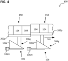
- Fig.4 4 illustrates the magnetron assembly 100 according to various embodiments 400 in a schematic side view or cross-sectional view.
- the transmission 106g of the actuator 106 has a sliding wedge 106k, which couples the motor 106m to the return plate 202p.
- a movement generated by the motor 106m can be converted into a translational movement of the sliding wedge 106k and transmitted to the return plate 202p by means of the sliding wedge 106k.
- the sliding wedge 106k achieves a self-locking effect of the actuator 106. In other words, the actuator 106 then does not necessarily need power to maintain the actual state. Once adjusted, the actual state of the actuator 106 thus remains unchanged. This reduces energy consumption.
- the self-locking effect can of course also be achieved in other ways, for example by means of a ball screw drive or the like.
- the actuator 106 can be set up to be self-locking.
- a self-locking actuator 106 may have one or more than one self-locking gear, for example.
- the self-locking gear may have a gear ratio of less than about 10%, e.g., less than about 5%, e.g., less than about 2%, e.g., less than about 1%. The smaller the transmission ratio, the better the self-locking effect.
- the self-locking gear can have a coefficient of static friction ⁇ which satisfies the following relationship: 0.5* ⁇ arctan( ⁇ ), where ⁇ designates the angle which the direction of movement of the gear and the sliding surface enclose with one another.
- the actuator 106 e.g. its gear 106g, can optionally be set up in such a way that the weight of the magnets 104 or return plate is sufficient as the restoring force. This further reduces the energy requirement.
- Fig.5 5 illustrates the magnetron assembly 100 according to various embodiments 500 in a schematic side view or cross-sectional view (viewed along the axis of rotation 311).
- Generator 308 may be located within tubular target 302 (if present). More generally, the generator 308 may be disposed within a circular cylinder as an envelope that is adjacent to the magnets 104 and whose cylinder axis is the axis of rotation 311 .
- the generator 308 can have a drive wheel 708 which is or can be brought into contact with the tubular target 302 . If the tubular target 302 is set in rotation, the rotational movement of the tubular target 302 can be coupled to the generator 308 by means of the drive wheel 708 .
- the drive wheel 708 can be coupled to a rotor of the generator 308 (also referred to as generator rotor) so that the coupled rotation is transmitted to the generator rotor.
- the generator 308 can also have a stator (also referred to as a generator stator), which is arranged in a stationary manner with respect to the carrier 102 . If the generator rotor is rotated relative to the generator stator, the generator can provide the supply voltage.
- the generator stator 308s and/or the generator rotor can be arranged next to the carrier 102 .
- the generator stator or the generator rotor can have a large number of coils which generate the supply voltage (by means of induction).
- the respective other of the generator stator or generator rotor can have a large number of magnets which stimulate the induction.
- the generator 308 can have a gearbox (also referred to as a generator gearbox) which has the drive wheel 708 .
- the generator gearbox can be set up to provide the generator rotor with a greater speed than is coupled into the drive wheel 708 .
- the generator gear can have a planetary gear or be formed from it. This is particularly compact and reliable.
- the planetary gear can, for example, be multi-stage (i.e. have several gear stages), e.g. three stages or more.
- Fig.6 6 illustrates the magnetron assembly 100 according to various embodiments 600 in a schematic side view or cross-sectional view (looking along the axis of rotation 311).
- Generator stator 308s and/or generator rotor 308r may surround carrier 102 .
- the generator rotor 308r can attached to or integrated into the tube target 302 so that its speed corresponds to the speed of the tube target 302 (also referred to as target speed).
- This configuration allows for a generator with a higher number of poles, which increases the supply voltage and thus the supply power that can be produced by the generator at the rated speed of the target (also referred to as the target speed).
- a high pole density (alternating pole density) clearly compensates for a slow rotary movement of the tubular target 302.
- the generator rotor 308r can have a multiplicity of magnets 502 (also referred to as generator magnets), which are attached to the inner wall of the tubular target 302 .
- the generator magnets 502 can also be attached to a cover (also referred to as a target cover) for the tubular target 302 .
- the target cover can, for example, cover the hollow space penetrating the tube target 302 .
- the generator stator 308s can have a plurality of coils 504 (also referred to as generator coils), which are supported by the carrier 102 and/or at least surround it.
- a plurality of coils 504 also referred to as generator coils
- Fig.7 7 illustrates the magnetron arrangement 100 according to various embodiments 700 in a schematic circuit diagram.
- 6 actuators 106 are shown as an example, although their number can also be larger or smaller.
- the magnetron arrangement 100 can have a control device 806 which generates the control signal.
- control signal can be used to communicate between the control device 806 and an actuator 106, for example bidirectionally.
- control signal can be the carrier of an information transmission between the control device 806 and an actuator 106 .
- control signal can be used to communicate between the control device 806 and the generator, for example in order to control and/or regulate its operating point.
- the control signal can clearly be an electrical signal, by means of which information can be transmitted, for example instructions, requests and/or responses.
- the communication by means of the control signal can take place, on a physical level, by means of an exchange of electrical power.
- the physical level of communication can be done using physical transmitters.
- the communication by means of the control signal can take place, on a logical level, by means of an exchange of information.
- the logical level of communication can take place by means of data processing, which can be implemented, for example, by means of a processor and/or a program and/or controls the transmitter.
- the exchange of electrical power can be modulated, for example, according to the information to be transmitted.
- the communication may be message based (i.e. based on messages) according to a communication protocol (e.g. a network protocol).
- a communication protocol e.g. a network protocol
- a fieldbus network protocol can be used as the communication protocol.
- a USB bus network protocol can be used as the communication protocol (Universal Serial Bus - USB).
- another communication protocol can also be used, which can be proprietary, for example.
- a message may address the actuator 106 to which the message is directed (ie show his address). Furthermore, the message can contain the information to be transmitted.
- the communication may be uni-directional (i.e. only from the controller to the actuator 106) or bi-directional (i.e. back and forth).
- the two-way communication may include driving from the controller 806 to the actuator 106 (also referred to as an inbound communication channel) and feedback from the actuator 106 to the controller 806 (also referred to as a return communication channel).
- control line 108a may provide one or more than one communication channel.
- Information transmitted from the control device 806 to the actuator 106 can represent, for example, the target state that the actuator 106 should assume.
- Information transmitted from an actuator 106 to the control device 806 can represent, for example, the actual state of the actuator 106 or an acknowledgment of receipt.
- the control line 108a can optionally have a communication interface 602 on the target coupling 301 .
- the communication interface 602 can be set up to exchange the control signal between the control device 806 and one or more than one of the actuators 106 .
- the communication interface 602 can be set up to forward the control signal, eg bidirectionally. This can be done by means of an optical coupling, inductive coupling and/or capacitive coupling. These achieve more reliable communication.
- Optical, inductive and/or capacitive transmission of the control signal can clearly bring about a galvanic isolation between actuator 106 and control device 806 . This galvanic isolation inhibits electrical interference in the operation of the Control device 806, which can have its cause, for example, in the rotational movement of the tube target 302, the power supply of the plasma via the tube target 302 and/or the plasma formation itself.
- the signal transmission can also be ohmic, i.e. the control device as the signal source and the actuator 106 as the signal receiver are ohmically coupled to one another.
- the communication interface 602 can be set up in such a way that the one or more than one communication channel is interrupted (i.e. opened) and established (ie closed) in time with the rotational movement of the tubular target, e.g. is interrupted and established alternately. This causes the communication to be clocked according to the rotation of the target (i.e. in time with the rotation).
- two communication channels can be established or interrupted alternately (i.e. in push-pull to each other).
- a communication channel can be established and interrupted alternately.
- the communication interface 602 can be set up as an angle-of-rotation-dependent switch which is open when the tube target is in a first position or a first angle of rotation range, and which is closed when the tube target is in a second position or a second angle of rotation range.
- this metered communication can be implemented at the physical level of communication and/or at the logical level of communication.
- the ohmic, optical, inductive and/or capacitive coupling may be physically broken (i.e. opened) and restored (i.e. closed) in time with the rotary motion of the tubular target, e.g. alternately.
- the logical communication e.g. the sending and/or receiving of data or entire messages
- the generator 308 can be set up to generate an open circuit voltage V0 as a supply voltage when the tube target 302 is in operation (for example at the target speed).
- This no-load voltage V0 can be applied to all actuators 106 or, by means of a multiplexer, can be applied individually to just one of the actuators 106 that is being controlled.
- the actuator 106 can accordingly consume electrical power, which is applied to adjust the magnetic field.
- the supply voltage can drop from the no-load voltage V0 to the rated voltage Vn.
- the system consisting of the generator as the power generator and the actuator as the power consumer assumes a fixed operating point which only has the target speed as a free parameter. In a first approximation, the target speed can be regarded as constant for the power balance and/or essentially correspond to the rated speed of generator 308 .
- the generator 308 can generate a corresponding electrical power (also referred to as generator nominal power) at the nominal voltage Vn, which is consumed by the actuator 106 .
- the generator 806 can be set up in such a way that the nominal generator power is greater than the power consumption of exactly one actuator 106, i.e. the nominal power consumed per actuator 106 (also referred to as consumer power). This means that an energy store can be dispensed with, which makes the energy supply less complex and therefore more reliable.
- the generator 806 can be set up in such a way that the generator rated power is less than the total power consumption of two actuators 106. This means that the generator can be built as compactly as possible and does not generate more power than is required.
- the load power per actuator 106 may be a function of the speed at which the magnetic field shifting occurs and a function of the mass displaced to shift the magnetic field (also referred to as a shifting operation).
- the more magnets that are used per actuator 106 the smaller the number of actuators 106. This makes the magnetron assembly 100 less complex and therefore more reliable.
- the magnetron arrangement 100 can, for example, have a number of 3 n or fewer magnets 104 per actuator 106, where n can be a natural number in the range from about 1 to about 10, e.g. in a range from about 1 to about 5, e.g a range from about 1 to about 3.
- the generator rating may be in a range from about 10 watts to about 50 watts.
- the rated power consumed (consumer power) per actuator 106 may be in a range from about 10 watts to about 50 watts and/or in a range from about half the generator power rating to about the generator power rating.
- the nominal speed of the generator or the target speed of the tubular target 302 can be in a range from about 5 rpm (revolutions per minute) to about 30 rpm.
- the mass of magnet system group 150 to be displaced per actuator 106 may be in a range from about 100 g (grams) to about 500 g.
- the or each actuator 106 may be set up to cover the actuating range (i.e. the range in which) in a time of approximately 1 s (second), e.g. in a range of approximately 0.5 s to approximately 5 s. This achieves a sufficient short reaction time for adjusting the magnetic field.
- the actuating range designates the range that is spanned by the most different possible actual states that the actuator 106 can assume.
- the magnetron arrangement 100 can also have one or more than one sensor 816 which is set up to detect the actual state (also referred to as the process state) of a sputtering process (e.g. coating process) provided by the magnetron arrangement 100 and/or the magnetic field. Controller 806 may be set up to control the actuators 106 based on the process state. For example, the actuating elements 106 can be activated on the basis of a predefined target state, for example in such a way that a difference between the process state and the target state is reduced.
- a sputtering process e.g. coating process
- a sensor can be part of a measurement chain that has a corresponding infrastructure (e.g. having a processor, storage medium and/or bus system or the like).
- the measuring chain can be set up to control the corresponding sensor, to process its detected measured variable as an input variable, and based thereon to provide an electrical signal as an output variable, which represents the actual state of the input variable at the time of detection.
- the measurement chain can be implemented, for example, by means of the control device 806 (e.g. a programmable logic controller - PLC).
- Each sensor 816 can be set up to record one or more than one measured variable as a representative of the process state.
- the measured variable can be an electrical, magnetic or optical measured variable, for example.
- multiple sensors 816 may be used to sense process status.
- one or more than one sensor 816 is arranged inside the tubular target 302, this can optionally have its own communication channel provided by means of the control line 108a.
- Fig.8 8 illustrates the magnetron arrangement 100 according to various embodiments 800 in a schematic perspective detailed view (looking at the axis of rotation 311) onto the target coupling 301.
- a physical level is explained. It can be understood that the aspects of the exemplary implementation at the physical level can also apply by analogy to an implementation at the logical level.
- a control line 108a with two communication channels 701a, 701b is illustrated here as an example, which can have, for example, an outgoing communication channel 701a and a returning communication channel 701b.
- the outbound communication channel 701a may be coupled to the transmitter (transmitting part of the transceiver) of the controller 806, for example.
- the feedback communication channel 701b can be coupled to the receiver (receiving part of the transceiver) of the controller 806, for example.
- the communication interface 602 may include: a first disk 702 arranged to be stationary relative to the carrier 102; a coupling diaphragm 704, which is mounted stationary relative to the tube target 302 or (if the tube target 302 is not yet mounted) to the component of the drive train 302a that drives the tube target 302; and a second disk 706 fixed in place relative to the carrier 102 .
- the first pane 702 and the second pane 706 can be configured to be stationary with respect to one another.
- the first pane 702 can be held by the carrier 102, for example.
- the second disk 706 can be held, for example, by means of an end block 312a, 312b.
- the first disk 702 and the second disk 706 can each have one or more than one (e.g. ring segment-shaped) plates 702a, 702b, e.g. several plates in the form of ring segments that continue one another (ie segments of a rings).
- the two plates 702a, 702b can have the same segment angle, for example in a range from about 140° to about 180°.
- the coupling orifice 704 may include one or more (e.g., ring segment-shaped) plates corresponding in shape to the one or more ring segments of the first disk 702 and the second disk 706 .
- Opposite plates can form a capacitor in pairs. Thus, two capacitors connected in series can be provided.
- a first capacitor is formed by the ring segment on the first stationary disk 706 and a ring segment on the rotating disk 704.
- the rotatable disc 704 is made of steel, for example, and/or forms a flange seal for the tubular target.
- a plastic disc e.g. about 2 mm thick
- the first ring segment forms the first capacitor with the ring segment 702a on the stationary disk 706.
- the plastic disc achieves electrical insulation and/or a reduction in the parasitic capacitance against the flange cover, which can be electrically at ground potential, for example.
- the plastic disk can, for example, have a thickness such that a breakdown voltage of the plastic disk exceeds the potential difference between tubular target and ground (e.g. approximately 2 mm or more).
- a disc made of a different dielectric can also be used.
- the first capacitor from the two ring segments 702a can have a capacitance of approximately 15 pF (picofarads), for example.
- the distance between the two ring segments 702a can be approximately 2 mm or less, for example.
- the two ring segments 702a can have an outer radius of about 110 mm and an inner radius of about 60 mm (millimeters, e.g. at an angle of about 180°.
- a similar arrangement of two ring segments 702a can form a second capacitor in the tubular target.
- the second condenser can be exposed to the cooling fluid, for example so that the cooling fluid penetrates between the two ring segments (which form the condenser plates) (illustratively since this second condenser is in the tubular target).
- the second capacitor has a larger capacitance, e.g., about 200 pF.
- the two capacitors are connected to one another by means of an electrically insulated wire through the disc 704 (e.g. target cover flange 704) and thus electronically form two capacitors connected in series.
- the capacitance of the two capacitors changes in time with the rotation of the tube target.
- the second ring segment 702b can provide a second transmission channel (e.g. reverse channel).
- One of the two channels can be used rotationally synchronously as a transmission channel for bidirectional transmission.
- the coupling aperture 704 can rotate relative to the first disk 702 and the second disk 706 .
- This implements a variable capacitor 602 as a communication interface 602, which alternately makes and breaks the two communication channels 701a, 701b. In this way, only one of the two communication channels 701a, 701b is connected at a time, within one rotation angle of the tube target 302.
- variable capacitor can have a stator provided by the second disk 706 and have a rotor provided by the coupling diaphragm 704 .
- the two ring segments 702a, 702b enable the transmission of the control signal to (by means of ring segment 702a) or from (by means of ring segment 702b) the actuators 106.
- variable capacitor 602 can also be less complex or more complex. If, for example, more than two communication channels 701a, 701b are to be provided, the segment angles can be smaller, corresponding to the multiple of the communication channels 701a, 701b. Alternatively or additionally, full rings or segments of several rings can also be used as capacitor plates, e.g. to establish several communication channels with one another at the same time.
- the communication interface 602 can have a first component (also referred to as a rotor or contact rotor) which is mounted in a stationary manner relative to the carrier 102 .
- the coupling device 602 can also have a second component (also referred to as a stator or contact stator), which is mounted stationary relative to the tubular target 302 or (if the tubular target 302 is not yet installed) to the component of the drive train 302a that drives the tubular target 302.
- the contact rotor and the contact stator can, for example, be at a distance from one another during operation and/or be galvanically separated from one another.
- the contact rotor and the contact stator can differ from one another, for example, in the number of their capacitor plates.
- a capacitor plate of the contact rotor Coupling in the capacitor plates of the contact stator alternately or one after the other or vice versa.
- the coupling diaphragm 704 can have a capacitor dielectric, which dielectrically couples the capacitor plates of the fixed (also referred to as stationary) components 702, 706 to one another.
- the capacitor dielectric can have a correspondingly high permittivity, e.g. greater than that of water or at least greater than 40.
- the first disk 702 and the second disk 706 can each have two contacts 702a, 702b, e.g. in the form of continuous ring segments (i.e. segments of a ring).
- the two contacts 702a, 702b may have the same segment angle, e.g., in a range from about 140° to about 180°.
- the coupling diaphragm 704 can have a ring segment which corresponds in shape to the ring segments of the first pane 702 and the second pane 706 .
- the coupling aperture 704 can rotate relative to the first disk 702 and the second disk 706 .
- This implements a rotary contact 602 as a communication interface 602, which alternately establishes and interrupts the two communication channels 701a, 701b. In this way, only one of the two communication channels 701a, 701b is connected at a time, within one rotation angle of the tube target 302.
- the rotary contact can have a stator provided by the second disk 706 and a Having a rotor provided by the coupling aperture 704 .
- the two contacts 702a, 702b enable the transmission of the control signal to (via contact 702a) or from (via contact 702b) the actuators 106.
- the structure of the rotary contact 602 can also be less complex or more complex. If, for example, more than two communication channels 701a, 701b are to be provided, the segment angles can be smaller, corresponding to the multiple of the communication channels 701a, 701b. Alternatively or additionally, full rings or segments of several rings can also be used as contacts, e.g. to establish several communication channels with one another at the same time.
- the communication interface 602 can have a first component (also referred to as a rotor or contact rotor) which is mounted in a stationary manner relative to the carrier 102 .
- the coupling device 602 can also have a second component (also referred to as a stator or contact stator), which is mounted stationary relative to the tubular target 302 or (if the tubular target 302 is not yet installed) to the component of the drive train 302a that drives the tubular target 302.
- the contact rotor and the contact stator can, for example, slide off one another during operation.
- the contact rotor and the contact stator can differ from one another, for example, in the number of their contacts.
- a contact of the contact rotor can touch the contacts of the contact stator alternately or one after the other, or vice versa.
- FIG. 11 illustrates the control signal of the magnetron assembly 100 according to various embodiments in one schematic diagram 900, in which an electrical quantity 901 of the control signal (for example its voltage or current) is plotted against time 903.
- the rotation time (period of the rotary movement) of the tubular target 302 is indicated here as t0.
- the control signal 902 can be subject to an interference 904 (also referred to as an interference signal 904), onto which the actual communication is modulated.
- the communication can be digital, for example, so that a sequence of pulses 906 is transmitted, the amplitude of which encodes the data to be transmitted, eg bits (eg 0 or 1). If the noise signal 904 is subtracted, the sequence of pulses 906 can be reconstructed. This achieves greater reliability of communication.
- the clocked communication shows that the communication takes place via the outgoing communication channel 701a in a first phase 911a of the period duration of the rotary movement; and that the communication via the return communication channel 701b occurs in a second phase of the period of rotation (e.g. after or before the first phase).
- the rotation time t0 of the rotary movement of the tubular target 302 can be in a range from approximately 0.01 s to approximately 1 s (second), for example.
- the speed i.e., the inverse of the round-trip time t0
- the speed may range from about 1 Hz to about 100 Hz (Hertz).
- the speed can be about 10 Hz.
- the transmission can have several gear stages that differ from one another, for example, in terms of their transmission ratio.
- the transmission can have a first gear stage with a first transmission ratio in a range from approximately 2 to approximately 4, for example approximately 2.
- the first gear stage can, for example, have a ring gear with approximately 120mm in diameter and a sprocket approximately 30mm in diameter.
- the transmission may have a second gear stage with a second gear ratio greater than the first gear ratio and/or greater than about 10, greater than about 25, or greater than about 50.
- the second gear ratio may be about 66 .
- the second gear stage can transfer the rotary movement to the rotor of the generator so that, for example, 24 V at 5000 rpm and/or a maximum of 50 watts are provided.
- the generator can optionally have at least one (ie one or more than one) supercapacitor (eg provided by means of Helmholtz double layers) for temporarily storing the generated power of the generator.
- the at least one supercapacitor can be operated according to a sequence which has a plurality of phases, a first phase of which supplies electrical power (taken from the rotational movement of the target) to the at least one supercapacitor, and a second phase of which has at least a supercapacitor to deliver electrical power to one or more actuators.
- the second phase may be shorter than the first phase, eg half the first phase or shorter, eg one fifth the first phase or shorter.
- the first phase (also referred to as the charging phase) can have a duration of 20 s or more.
- the second phase (also referred to as the discharge phase) can have a duration of 2 s or less. This achieves the ability to build the generator even smaller and/or to be able to retrofit existing systems without having to change their tube target drive (also referred to as target drive).
- a target drive can deliver about 40 Nm or less.
- the torque transmitted to the tubular target by means of the generator can be in a range from approximately 0.5 Nm to approximately 1 Nm.
- the generation of energy by means of the generator can be operated in a regulated manner (e.g. by means of the control device), so that the generator withdraws approximately 1 W or less from the rotary motion of the tubular target.
- Example 1 is a magnetron assembly according to claim 1 comprising, inter alia: a bearing assembly including a (e.g. elongate) support (e.g. a support tube) for supporting a tubular target in which the support extends along (e.g. into) the bearing assembly ) is; one or more than one magnet system group (e.g. multiple magnet system groups) comprising a plurality of magnets and an electrical actuator, the actuator being configured to adjust a position of the plurality of magnets relative to the carrier in response to an electrical control signal supplied to the actuator; an electrical generator which is set up to provide electrical power based on a rotational movement of the target (e.g. to convert the rotational movement into electrical power) and to supply it to the actuator.
- a bearing assembly including a (e.g. elongate) support (e.g. a support tube) for supporting a tubular target in which the support extends along (e.g. into) the bearing assembly ) is; one or more than one magnet system group (e.
- Example 2 is a magnetron arrangement according to claim 1, comprising, inter alia: a bearing arrangement which has a (e.g. elongate) carrier (e.g. a carrier tube) for (e.g. rotatable or stationary) supporting a (eg, tubular or plate-shaped) target in which the support extends along (eg, extends into) the bearing assembly; several magnet system groups (also referred to as magnet system segments), which are arranged one behind the other and coupled to the carrier and of which each magnet system group has: a return plate, several (e.g. three) magnets, which are magnetically coupled to one another by means of the return plate; (eg, precisely) an electrical actuator configured to adjust a position of the return plate relative to the carrier in response to an electrical control signal supplied to the actuator.
- a bearing arrangement which has a (e.g. elongate) carrier (e.g. a carrier tube) for (e.g. rotatable or stationary) supporting a (eg, tubular or plate-
- Example 3 is a magnetron assembly according to claim 1, including, among other things: a bearing assembly including a support (eg, a support tube) for supporting a target into which the support extends; one or more than one magnet system group (e.g. several magnet system groups), of which each magnet system group has: an optional yoke plate, at least three magnets, (e.g. exactly) an electrical actuator which is set up, a position of the yoke plate and/or the at least three magnets relative to the carrier in response to an electrical control signal supplied to the actuator; an electrical generator which is set up to provide electrical power based on a rotary movement of the target (e.g. the rotary movement in the to convert electrical power) and to supply it to the actuator.
- a bearing assembly including a support (eg, a support tube) for supporting a target into which the support extends; one or more than one magnet system group (e.g. several magnet system groups), of which each magnet system group has: an optional yoke plate, at least three magnets
- Example 4 is the magnetron assembly according to any one of Examples 1 to 3, wherein a number of the plurality of magnet system groups is greater than a number of magnets per magnet system group and/or wherein the number of magnet system groups is 10 or more (eg, 15 or more); and/or wherein the number of magnet system groups is 20 or less (e.g. 16).
- Example 5 is the magnetron arrangement according to one of Examples 1 to 4, - further comprising: one or more than one additional magnet system group (e.g. passive magnet system group), of which each additional magnet system group is arranged between two immediately adjacent magnet system groups of the several magnet system groups and has a return plate , which is coupled to the return plate of the two immediately adjacent magnet system groups, wherein optionally each of the two immediately adjacent magnet system groups has at least one actuator more than each additional magnet system group.
- additional magnet system group e.g. passive magnet system group
- Example 6 see for example also the magnetron arrangement according to claim 14, is the magnetron arrangement according to one of examples 1 to 5, each magnet system group having exactly one electrical actuator; and/or wherein each additional magnet system group is free of an actuator.
- Example 7 see for example also the magnetron arrangement according to claim 2, the magnetron arrangement is according to a of Examples 1 to 6, wherein the bearing assembly includes a drive train for driving rotation of the target (eg, if tubular).
- the target eg, if tubular
- Example 8 is the magnetron assembly according to any one of Examples 1 to 7, wherein the generator is supported by the beam.
- Example 9 is the magnetron assembly according to any one of Examples 1 to 8, wherein the electric actuator includes or is formed from an electric actuator (e.g., motor or piezo element).
- an electric actuator e.g., motor or piezo element
- Example 10 is the magnetron assembly according to any one of Examples 1 to 9, wherein the support comprises or is formed from a tube (also referred to as a lance tube) (e.g. when the target is tubular); or wherein the support comprises or is formed from a frame (e.g. when the target is plate-shaped).
- a tube also referred to as a lance tube
- the support comprises or is formed from a frame (e.g. when the target is plate-shaped).
- Example 11 is the magnetron assembly according to any one of Examples 1 to 10, wherein the bearing assembly has one (in cantilever configuration) or more than one support area for supporting the target (e.g. each support area provided by means of an end block).
- Example 12 see for example also the magnetron arrangement according to claim 3, is the magnetron arrangement according to one of examples 1 to 11, wherein the bearing arrangement has a first end block and/or a second end block, between which, for example, the generator is arranged; for example each end block of the bearing arrangement having a coupling device rotatably mounted relative to the carrier for coupling the tubular target.
- Example 13 is the magnetron assembly according to Example 12, wherein the first end block includes a or the drive train for transmitting torque to the coupling device; and/or wherein the second end block has a plurality of fluid lines for exchanging a fluid by means of the Has coupling device (e.g. for interchanging between the carrier and the second end block).
- Example 14 is the magnetron assembly according to any one of Examples 1 to 13, further comprising: a controller configured to control the actuator of each magnet system group, e.g. based on an actual state of a process (e.g. coating process) performed by the magnetron assembly.
- a controller configured to control the actuator of each magnet system group, e.g. based on an actual state of a process (e.g. coating process) performed by the magnetron assembly.
- Example 15 is the magnetron assembly according to Example 14, wherein the controller is configured to sequentially drive the actuator of each magnet system group.
- Example 16 is the magnetron assembly according to any one of Examples 1 to 15, wherein the communication interface is a component of a target lid.
- Example 17 see for example also the magnetron arrangement according to claim 1, is the magnetron arrangement according to example 16, wherein the communication interface is the discontinuous
- variable capacitor which is mechanically coupled to the rotary motion.
- Example 18 is the magnetron arrangement according to example 17, wherein the variable capacitor has a broken rotational symmetry and/or mirror symmetry and/or multiple is set up; and/or wherein the variable capacitor has a stator and a rotor, wherein the stator is arranged to be stationary relative to the carrier and wherein the rotor arranged to be movable relative to the carrier for coupling to the rotary movement.
- Example 19 is the magnetron assembly according to example 18, wherein the stator and/or the rotor of the variable capacitor have a ring segment, the ring segment having a segment angle of 270° or less (e.g. 180° or less), for example.
- Example 20 see for example also the magnetron arrangement according to claim 10, is the magnetron arrangement according to one of examples 1 to 19, wherein the actuator has a self-locking gear, for example the self-locking gear has a sliding wedge and/or a self-locking thread.
- Example 21 is the magnetron assembly according to any one of Examples 1 to 20, wherein a number of magnets per actuator is seven or less, e.g., six or less, e.g., three or less.
- Example 22 see also the magnetron arrangement according to claim 4, for example, is the magnetron arrangement according to one of examples 1 to 21, wherein the electric generator has a transmission which is set up to convert the rotational movement of the target at first speed coupled to the generator into a rotational movement at second speed to convert, wherein the second speed is different from (e.g. greater than) the first speed.
- Example 23 see for example also the magnetron arrangement according to claim 5, the magnetron arrangement according to Example 22, wherein the gear comprises or is formed from a planetary gear.
- Example 24 is the magnetron assembly according to any one of Examples 1 to 23, wherein an electric power of electric generator is in a range from about 1 watt to about 50 watts, eg in a range from about 10 watts to about 50 watts.
- Example 25 see for example also the magnetron arrangement according to claim 13, is the magnetron arrangement according to one of Examples 1 to 24, wherein all magnets (optionally together with the return plate) of each magnet system group together have a weight of less than 500 grams (e.g. 100 grams). .
- Example 26 is the magnetron assembly according to any one of Examples 1 to 25, wherein an extension of each magnet system group (along an axis of rotation of rotation) is about 10 cm (centimeters) or less, e.g., about 5 cm or less, e.g., about 1 cm or less; or in a range from about 4 cm to about 10 cm, for example about 6 cm.
- Example 27 see for example also the magnetron arrangement according to claim 14 or 15, is the magnetron arrangement according to one of Examples 1 to 26, wherein each magnet system group is magnetically three-pole (ie has three magnetic poles), for example each magnetic pole has one of the magnets or formed therefrom, or wherein, for example, each magnetic pole has a set of magnets whose length is, for example, an integer multiple (eg the length of the magnet system group) (eg if the sets differ in the length of the magnets).
- the inner pole can have three magnets each 20 mm long and each outer pole can have two magnets each 30 mm long (so that the magnet system group has exactly 7 magnets).
- Example 28 is the magnetron assembly according to any one of Examples 1 to 27, wherein the electric generator is a having a stator through which the beam extends; and/or wherein the electrical generator has a rotor through which the carrier extends.
- Example 29 is the magnetron assembly according to Example 28, further comprising: the target, which comprises, for example, the rotor of the generator or at least holds the rotor of the generator.
- Example 30 is the magnetron assembly according to any one of Examples 1 to 29, wherein the electric generator is disposed adjacent to the substrate.
- Example 31 see for example also the magnetron assembly according to claim 6, is the magnetron assembly according to any one of examples 1 to 30, wherein the actuator has a scissors gear.
- Example 32 is the magnetron assembly according to any one of Examples 1 to 31, wherein the actuator has a linear gear.
- Example 33 see also e.g. the magnetron assembly according to claim 7, is the magnetron assembly according to any one of examples 1 to 32, wherein the actuator comprises a sliding wedge which is arranged, for example, to adjust the position of the plurality of magnets relative to the support in response to a to set the movement transmitted to the sliding wedge (e.g. by means of a stamp).
- the actuator comprises a sliding wedge which is arranged, for example, to adjust the position of the plurality of magnets relative to the support in response to a to set the movement transmitted to the sliding wedge (e.g. by means of a stamp).
- Example 34 is the magnetron arrangement according to one of Examples 1 to 33, wherein an electrical power consumed per actuator when adjusting the position of the return plate relative to the carrier in a range from about 50% (e.g. 75%) to about 100% of a nominal power of the generator or more than the rated power of the generator.
- Example 35 is the magnetron assembly according to Example 34, further comprising: at least one supercapacitor that is alternately coupled to the generator and an actuator.
- Example 36 is the magnetron assembly according to example 35, wherein the at least one supercapacitor is alternately coupled to the generator and the actuator according to a sequence (e.g. controlled by a controller), the cycle having a first phase in which the generator gives the supercapacitor a first supplies electrical power, the cycle including a second phase in which the supercapacitor supplies a second electrical power to the actuator, for example, wherein the second phase is shorter than the first phase and/or wherein the second power is greater than the first power.
- a sequence e.g. controlled by a controller
- Example 37 is the magnetron arrangement according to one of Examples 1 to 36, which is free of an electrochemical energy store.
- Example 38 is the magnetron assembly according to any one of Examples 1 to 37, which is free of a capacitive energy storage device (which is coupled between a coil of the generator and an actuator, for example).
- Example 39 is the magnetron assembly according to any one of Examples 1 to 38, which is free of a capacitive storage capacitance greater than about 50% (eg, 75%) one upon setting the position of the backing plate per Actuator absorbed energy.
- Example 40 is a processing arrangement comprising: a vacuum processing chamber; and a magnetron assembly disposed in the vacuum processing chamber according to any one of Examples 1 to 39.
- Example 41 is the processing arrangement according to example 40, comprising: a control device arranged outside the vacuum processing chamber, which is set up to supply the control signal to the magnetron arrangement and/or to control and/or regulate an operating point of the generator; and/or a transport device for transporting a substrate towards, away from or past the magnetron arrangement.
- Example 42 is the processing arrangement according to example 41, with the control device being set up to regulate the operating point of the generator, e.g.
Landscapes
- Chemical & Material Sciences (AREA)
- Engineering & Computer Science (AREA)
- Physics & Mathematics (AREA)
- Plasma & Fusion (AREA)
- Analytical Chemistry (AREA)
- Chemical Kinetics & Catalysis (AREA)
- Materials Engineering (AREA)
- Mechanical Engineering (AREA)
- Metallurgy (AREA)
- Organic Chemistry (AREA)
- Physical Vapour Deposition (AREA)
Description
- Verschiedene Ausführungsbeispiele betreffen eine Magnetronanordnung.
- Im Allgemeinen können Werkstücke oder Substrate prozessiert, z.B. bearbeitet, beschichtet, erwärmt, geätzt und/oder strukturell verändert werden. Ein Verfahren zum Beschichten eines Substrats ist beispielsweise die Kathodenzerstäubung (das so genannte Sputtern). Mittels Sputterns kann beispielsweise eine Schicht oder können mehrere Schichten auf einem Substrat abgeschieden werden. Dazu kann mittels einer Kathode ein plasmabildendes Gas ionisiert werden, wobei mittels des dabei gebildeten Plasmas ein abzuscheidendes Material (Targetmaterial) der Kathode zerstäubt werden kann. Das zerstäubte Targetmaterial kann anschließend zu einem Substrat gebracht werden, an dem es sich abscheiden und eine Schicht bilden kann.
- Modifikationen der Kathodenzerstäubung sind das Sputtern mittels eines Magnetrons, das so genannte Magnetronsputtern oder das so genannte reaktive Magnetronsputtern. Dabei kann das Bilden des Plasmas mittels eines Magnetfeldes unterstützt werden, wobei mittels des Magnetfeldes beispielsweise die Ionisationsrate des plasmabildenden Gases erhöht werden kann. Zum Erzeugen des Magnetfeldes kann relativ zu der Kathode ein Magnetsystem derart angeordnet sein oder werden, dass an der Oberfläche des Targetmaterials (Targetoberfläche) ein Plasmakanal, ein so genannter Race-Track, ausgebildet werden kann, in dem sich Plasma bilden kann. Dabei kann das Targetmaterial an den Stellen zerstäubt werden, an denen der Plasmakanal verläuft.
- Wird während des Sputterns das Targetmaterial zerstäubt und dabei verbraucht, kann das Targetmaterial dünner werden, wobei der Abstand der Oberfläche des Targetmaterials zu dem Magnetsystem reduziert werden kann. Aus dem veränderten Abstand kann eine Änderung des Magnetfeldes auf der Targetoberfläche resultieren, was das Zerstäuben von Targetmaterial und damit das Abscheiden einer Schicht aus dem zerstäubten Targetmaterial beeinflussen kann. Anschaulich kann sich eine Abscheidungscharakteristik aufgrund des Verbrauchs an Targetmaterial im Verlauf des Sputterns verändern.
- Ein gleichmäßiges Zerstäuben von Targetmaterial kann daher ein präzises Einrichten des Magnetsystems relativ zu der Kathode erfordern, um anschaulich eine möglichst gleichmäßige Geometrie (z.B. einer magnetischen Flussdichte oder eines magnetischen Feldgradienten) des Magnetfelds auf der Targetoberfläche zu erhalten.
- Bekannte Beispiele von Magnetronsystemen mit rotierendem Target, bei denen die Position der Magnete in Bezug auf das Target verändert wird sind aus
EP 3 137 646 A1 ,DE 10 2014 109991 A1 ,US 2014/097080 A1 undUS 2011 /155568 A1 bekannt. - Durch die Erfindung, definiert von der Magnetronanordnung gemäß Anspruch 1, wird unter anderem ein gleichmäßigeres Zerstäuben eines Targetmaterials aufgrund eines präziseren Einrichtens des Magnetsystems relativ zu der Kathode erreicht. Weitere erfinderische Ausführungsformen sind in den abhängigen Ansprüchen definiert.
- Ein Aspekt verschiedener Ausführungsformen kann anschaulich darin gesehen werden, dass ein verstellbares Magnetfeld bereitgestellt wird. Mittels Stellens des Magnetfeldes kann ein Zerstäuben des Targetmaterials beeinflusst werden, beispielsweise derart, dass ein möglichst gleichmäßiges Zerstäuben und/oder Beschichten erfolgen kann. Zum Stellen des Magnetfeldes kann beispielsweise eine Lage (d.h. Position und/oder Ausrichtung) der Magnete des Magnetsystems relativ zueinander und/oder relativ zu dem Target gestellt werden.
- Gemäß verschiedenen Ausführungsformen wurde anschaulich erkannt, dass die herkömmlicherweise zum Stellen des Magnetfeldes verwendete Elektronik zu fehleranfällig und zu unhandlich ist. Die verwendete Elektronik ist im Betrieb beständig einer erhöhten Belastung ausgesetzt, da diese wasserumflossen und elektrischen Schwankungen ausgesetzt ist. Anschaulich wurde erkannt, dass dies verbesserte werden kann, indem die elektrische Wechselwirkungskette verbessert wird. Zu der Wechselwirkungskette gehören beispielsweise die Energieversorgungskette, d.h. die Kette von der Energieerzeugung bis zum Energieverbrauch, und die Kommunikationskette.
- Die gemäß verschiedenen Ausführungsformen bereitgestellte elektrische Wechselwirkungskette ist kompakter, zuverlässiger und weniger komplex.
- Beispielsweise wurde erkannt, dass eine Energieerzeugung innerhalb des rotierenden Targets die Energieversorgungskette erheblich verkürzt und die Wartungsintervalle deutlich vergrößert. In dem Zusammenhang wurde erkannt, dass eine Energieerzeugung innerhalb des Targets zuverlässiger wird, wenn der Energieverbrauch für ein Stellen des Magnetfeldes verringert wird. Unter anderem wurde erkannt, dass es eine geringere Dimensionierung des Energieverbrauchs ermöglicht, auch die Dimensionierung der Energieerzeugung zu verringern, so dass alle Komponenten der Energieversorgungskette kompakter werden können, was das Risiko für Ausfälle verringert, die Energieversorgung zuverlässiger macht und Reparaturen erleichtert.
- Gemäß verschiedenen Aspekten werden anschaulich mehrere identisch aufgebaute Magnetsystemgruppen (auch als Magnetbaugruppe bezeichnet) bereitgestellt, von denen jede Magnetsystemgruppe mehrere Magnete samt Stellantrieb aufweist, und somit schnell und als Baugruppe kostengünstig getauscht bzw. betrieben werden können.
- Gemäß verschiedenen Aspekten werden anschaulich eine Vielzahl Magnetbaugruppen bereitgestellt, die eine möglichst geringe Anzahl Magnete aufweisen, was deren Gewicht und damit den Energieverbrauch pro Stellvorgang, der das Magnetfeld stellt, verringert. Dies erreicht, dass der Generator weniger Leistung bereitstellen muss, so dass der Generator kompakter gebaut werden kann.
- Es zeigen
- Figur 1
- bis 6 und 8 jeweils eine Magnetronanordnung gemäß verschiedenen Ausführungsformen in verschiedenen schematischen Ansichten;
- Figur 7
- eine Magnetronanordnung gemäß verschiedenen Ausführungsformen in einem schematischen Verschaltungsdiagramm; und
- Figur 9
- das Steuersignal der Magnetronanordnung gemäß verschiedenen Ausführungsformen in einem schematischen Diagramm.
- In der folgenden ausführlichen Beschreibung wird auf die beigefügten Zeichnungen Bezug genommen, die Teil dieser bilden und in denen zur Veranschaulichung spezifische Ausführungsformen gezeigt sind, in denen die Erfindung ausgeübt werden kann. In dieser Hinsicht wird Richtungsterminologie wie etwa "oben", "unten", "vorne", "hinten", "vorderes", "hinteres", usw. mit Bezug auf die Orientierung der beschriebenen Figur(en) verwendet. Da Komponenten von Ausführungsformen in einer Anzahl verschiedener Orientierungen positioniert werden können, dient die Richtungsterminologie zur Veranschaulichung und ist auf keinerlei Weise einschränkend. Es versteht sich, dass andere Ausführungsformen benutzt und strukturelle oder logische Änderungen vorgenommen werden können, ohne von dem Schutzumfang der vorliegenden Erfindung abzuweichen. Es versteht sich, dass die Merkmale der hierin beschriebenen verschiedenen beispielhaften Ausführungsformen miteinander kombiniert werden können, sofern nicht spezifisch anders angegeben. Die folgende ausführliche Beschreibung ist deshalb nicht in einschränkendem Sinne aufzufassen, und der Schutzumfang der vorliegenden Erfindung wird durch die angefügten Ansprüche definiert.
- Im Rahmen dieser Beschreibung werden die Begriffe "verbunden", "angeschlossen" sowie "gekoppelt" verwendet zum Beschreiben sowohl einer direkten als auch einer indirekten Verbindung (z.B. ohmsch und/oder elektrisch leitfähig, z.B. einer elektrisch leitfähigen Verbindung), eines direkten oder indirekten Anschlusses sowie einer direkten oder indirekten Kopplung. In den Figuren werden identische oder ähnliche Elemente mit identischen Bezugszeichen versehen, soweit dies zweckmäßig ist.
- Gemäß verschiedenen Ausführungsformen kann der Begriff "gekoppelt" oder "Kopplung" im Sinne einer (z.B. mechanischen, hydrostatischen, thermischen und/oder elektrischen), z.B. direkten oder indirekten, Verbindung und/oder Wechselwirkung verstanden werden. Mehrere Elemente können beispielsweise entlang einer Wechselwirkungskette miteinander gekoppelt sein, entlang welcher die Wechselwirkung (z.B. ein Signal) übertragen werden kann. Beispielsweise können zwei miteinander gekoppelte Elemente eine Wechselwirkung miteinander austauschen, z.B. eine mechanische, hydrostatische, thermische und/oder elektrische Wechselwirkung. Gemäß verschiedenen Ausführungsformen kann "gekuppelt" im Sinne einer mechanischen (z.B. körperlichen bzw. physikalischen) Kopplung verstanden werden, z.B. mittels eines direkten körperlichen Kontakts. Eine Kupplung kann eingerichtet sein, eine mechanische Wechselwirkung (z.B. Kraft, Drehmoment, etc.) zu übertragen.
- Als Steuern kann eine beabsichtigte Beeinflussung eines Systems verstanden werden. Dabei kann der momentane Zustand des Systems (auch als Ist-Zustand bezeichnet) gemäß einer Vorgabe (auch als Soll-Zustand bezeichnet) verändert werden. Regeln kann als Steuern verstanden werden, wobei zusätzlich einer Zustandsänderung des Systems durch Störungen entgegengewirkt wird. Anschaulich kann die Steuerung eine nach vorn gerichtete Steuerstrecke aufweisen und somit anschaulich eine Ablaufsteuerung implementieren, welche eine Eingangsgröße (z.B. die Vorgabe) in eine Ausgangsgröße umsetzt. Die Steuerstrecke kann aber auch Teil eines Regelkreises sein, so dass eine Regelung implementiert wird. Die Regelung weist im Gegensatz zu der reinen vorwärts gerichteten Ablaufsteuerung eine fortlaufende Einflussnahme der Ausgangsgröße auf die Eingangsgröße auf, welche durch den Regelkreis bewirkt wird (Rückführung). Mit anderen Worten kann alternativ oder zusätzlich zu der Steuerung eine Regelung verwendet werden bzw. alternativ oder zusätzlich zu dem Steuern ein Regeln erfolgen. Der Zustand des Systems (auch als Arbeitspunkt bezeichnet) kann von einer oder mehr als einer Regelgröße des Systems repräsentiert werden, deren Ist-Wert den Ist-Zustand des Systems und deren Soll-Wert (auch als Führungswert bezeichnet) den Soll-Zustand des Systems repräsentiert. Bei einer Regelung wird ein Ist-Zustand des Systems (z.B. basierend auf einer Messung ermittelt) mit dem Soll-Zustand des Systems verglichen und die eine oder mehr als eine Regelgröße mittels einer entsprechenden Stellgröße (unter Verwendung eines Stellglieds) derart beeinflusst, dass die Abweichung des Ist-Zustands von dem Soll-Zustand des Systems minimiert wird.
- Das Steuern und/oder Regeln kann gemäß verschiedenen Ausführungsformen mittels einer Steuervorrichtung implementiert werden. Der Begriff "Steuervorrichtung" kann als jede Art einer Logik implementierenden Entität verstanden werden, die beispielsweise eine Verschaltung und/oder einen Prozessor aufweisen kann, welche Software ausführen kann, die in einem Speichermedium, in einer Firmware oder in einer Kombination davon gespeichert ist, und darauf basierend Anweisungen ausgeben kann. Die Steuervorrichtung kann beispielsweise mittels Codesegmenten (z.B. Software) konfiguriert sein, um den Betrieb eines Systems (z.B. seines Arbeitspunkts) zu steuern. Der Arbeitspunkt kann den Punkt im Kennfeld oder auf der Kennlinie eines technischen Gerätes beschreiben, der aufgrund der Systemeigenschaften und einwirkenden äußeren Einflüsse und Parameter des Gerätes eingenommen wird. Der Arbeitspunkt kann anschaulich beschreiben, welchen Betriebszustand (d.h. Ist-Zustand) das Gerät aufweist.
- Der Begriff "Prozessor" kann als jede Art von Entität verstanden werden, die die Verarbeitung von Daten oder Signalen erlaubt. Die Daten oder Signale können beispielsweise gemäß zumindest einer (d.h. einer oder mehr als einer) spezifischen Funktion behandelt werden, die vom Prozessor ausgeführt wird. Ein Prozessor kann eine analoge Schaltung, eine digitale Schaltung, eine Mischsignalschaltung, eine Logikschaltung, einen Mikroprozessor, eine zentrale Verarbeitungseinheit (CPU), eine Grafikverarbeitungseinheit (GPU), einen digitalen Signalprozessor (DSP), eine programmierbare Gatter-Anordnung (FPGA), eine integrierte Schaltung oder eine beliebige Kombination davon aufweisen oder daraus gebildet sein. Jede andere Art der Implementierung der jeweiligen Funktionen, die nachstehend ausführlicher beschrieben werden, kann auch als Prozessor oder Logikschaltung verstanden werden, beispielsweise auch virtuelle Prozessoren (oder eine virtuelle Maschine) oder eine Vielzahl dezentraler Prozessoren, die beispielsweise mittels eines Netzwerks miteinander verbunden sind, beliebig räumlich verteilt sind und/oder beliebige Anteile an der Implementierung der jeweiligen Funktionen haben (z.B. Rechenlastverteilung unter den Prozessoren). Dasselbe gilt im Allgemeinen für eine anders implementierte Logik zur Implementierung der jeweiligen Funktionen. Es versteht sich, dass einer oder mehrere der hierin detailliert beschriebenen Verfahrensschritte von einem Prozessor ausgeführt (z.B. realisiert) werden können, durch eine oder mehrere spezifische Funktionen, die von dem Prozessor ausgeführt werden.
- Das Steuern und/oder Regeln kann aufweisen, dass von der Steuervorrichtung Instruktionen als Informationen an das Stellglied übertragen werden, welche von dem Stellglied umgesetzt werden (mittels Stellens des Stellglieds). Dazu kann das Stellglied in analoger Weise einen Prozessor aufweisen, welcher eingerichtet ist, die Instruktionen zu interpretieren und gemäß der entsprechenden Funktion des Stellglieds umzusetzen. Als Beispiel kann eine Instruktion einen Soll-Wert aufweisen, welche das Stellglied einnehmen soll. Als anderes Beispiel kann eine Instruktion eine Soll-Veränderung aufweisen, welche das Stellglied ausführen soll.
- Die Übertragung einer Information (auch als Informationsübertragung oder Kommunikation bezeichnet) kann gemäß verschiedenen Ausführungsformen gemäß einem Kommunikationsprotokoll (KP) erfolgen. Die Informationsübertragung kann aufweisen, eine Nachricht, welche die Information aufweist, gemäß dem Kommunikationsprotokoll zu erzeugen und/oder zu übermitteln. Das Kommunikationsprotokoll kann anschaulich eine Vereinbarung, nach der die Informationsübertragung zwischen zwei oder mehreren Parteien abläuft bezeichnen. In seiner einfachsten Form kann das Kommunikationsprotokoll definiert werden als eine Menge von Regeln, welche die Syntax, Semantik und Synchronisation der Informationsübertragung festlegen. Das oder die eingesetzten Kommunikationsprotokolle (z.B. ein oder mehrere Netzwerkprotokolle) können grundsätzlich beliebig ausgewählt werden und können (müssen aber nicht) gemäß dem OSI (Open System Interconnect)-Referenzmodell konfiguriert sein. In den jeweiligen Protokollschichten können ebenfalls beliebige Protokolle eingesetzt werden.
- Der Begriff "Sputtern" bezeichnet das Zerstäuben eines Materials (auch als Beschichtungsmaterial oder Targetmaterial bezeichnet) mittels eines Plasmas. Die zerstäubten Bestandteile des Targetmaterials werden somit voneinander separiert und können beispielsweise zum Bilden einer Schicht woanders angelagert werden. Das Sputtern kann mittels einer sogenannten Sputtervorrichtung erfolgen, welche ein Magnetsystem aufweisen kann (dann auch als Magnetron bezeichnet).
- Zum Sputtern kann das Magnetron in einer Vakuum-Prozessierkammer angeordnet werden, so dass das Sputtern in einem Vakuum erfolgen kann. Dazu können die Umgebungsbedingungen (die Prozessbedingungen) innerhalb der Vakuum-Prozessierkammer (z.B. Druck, Temperatur, Gaszusammensetzung, usw.) während Sputterns eingestellt oder geregelt werden. Die Vakuum-Prozessierkammer kann beispielsweise luftdicht, staubdicht und/oder vakuumdicht eingerichtet sein oder werden, so dass innerhalb der Vakuum-Prozessierkammer eine Gasatmosphäre mit einer vordefinierten Zusammensetzung oder einem vordefinierten Druck (z.B. gemäß einem Sollwert) bereitgestellt werden kann. Beispielsweise kann innerhalb der Vakuum-Prozessierkammer ein ionenbildendes Gas (Prozessgas) oder ein Gasgemisch (z.B. aus einem Prozessgas und einem Reaktivgas) in der Prozesskammer bereitgestellt sein oder werden. Bei einem reaktiven Magnetronsputtern kann das zerstäubte Material beispielsweise mit einem Reaktivgas reagiert und das Reaktionsprodukt abgeschieden werden.
- Um das Targetmaterial effektiv zu zerstäuben (auch als Sputtern bezeichnet), kann das Targetmaterial um das Magnetsystem herumgedreht werden. Dazu kann das Targetmaterial rohrförmig, als so genanntes Rohrtarget, eingerichtet sein, wobei das Magnetsystem im Inneren des Rohrtargets angeordnet sein kann, so dass das Rohrtarget um das Magnetsystem gedreht werden kann. Das Rohrtarget kann beispielsweise ein Rohr aufweisen auf dem das Targetmaterial als Schicht auf einer äußeren Mantelfläche des Rohrs befestigt sein kann und die Mantelfläche des Rohrs teilweise bedecken kann. Das Rohrtarget kann aber auch aus dem Targetmaterial gebildet sein.
- Das Zerstäuben von Targetmaterial mittels Sputterns kann mit einer räumlichen Verteilung erfolgen, wobei die räumliche Verteilung des zerstäubten Targetmaterials von dem Ist-Zustand des Sputterns abhängen kann. Parameter (die sogenannten Prozessparameter) des Ist-Zustands des Sputterns weisen beispielsweise auf: die Zusammensetzung und/oder Temperatur des Plasmas, die Beschaffenheit des Targetmaterials, die Prozessspannung; die Form und/oder Geometrie des Magnetfeldes und/oder der Druck des ionenbildenden Gases. Mittels Anpassens des Magnetsystems bzw. des damit erzeugten Magnetfeldes können Abweichungen vom Soll-Zustand des Sputterns (auch als Sputterprozess bezeichnet) reduziert werden, was die Eigenschaften der abgeschiedenen Schicht verbessert. Die Prozessspannung kann an dem Targetmaterial anliegen, welches im Betrieb die Funktion der Kathode zum Bilden des Plasmas implementiert. Daher wird das Target auch als Kathode bezeichnet (im drehbaren Fall auch dann auch als Rohrkathode bezeichnet).
- Zum Sputtern kann in einer Vakuum-Prozessierkammer gemäß verschiedenen Ausführungsformen eine Magnetronanordnung mit einem Rohrtarget und einem Magnetsystem in dem Rohrtarget angeordneten werden. Das Rohrtarget kann an gegenüberliegenden Endabschnitten mittels so genannter Endblöcke drehbar gelagert sein oder werden, wobei die Endblöcke ein Versorgen der Rohrtarget (z.B. mit elektrischer Leistung und Kühlfluid) bereitstellen können.
- Allgemeiner gesprochen wird hierin auf eine Lageranordnung Bezug genommen, welche zum Lagern eines Rohrtargets einen oder mehr als einen Endblock aufweisen kann.
- Weist die Lageranordnung zwei Endblöcke auf, kann jeweils einer der Endblöcke (der sogenannte Antriebsendblock) einen Antriebsstrang aufweisen, der mit einem Antrieb (auch als Targetantrieb bezeichnet) zum Drehen des Rohrtargets gekuppelt ist; und der jeweils andere der Endblöcke (der sogenannte Medienendblock) kann eine Fluidleitung zum Zuführen und Abführen von Kühlfluid (z.B. ein wasserbasiertes Gemisch) aufweisen, welches durch das Target hindurch geleitet werden kann. Die zwei Endblöcke werden beispielsweise an einer Kammerdecke (d.h. einem Kammerdeckel) hängend montiert.
- Es kann allerdings auch genau ein Endblock (auch als Kompaktendblock bezeichnet) verwendet werden, welcher den Antriebsstrang und die Fluidleitung aufweist und somit die Funktionen eines Antriebsendblocks und eines Medienendblocks gemeinsam bereitstellt. Die dem Kompaktendblock gegenüberliegende Seite des Rohrtargets kann beispielsweise frei auskragen (d.h. frei hängen), was als Cantilever-Konfiguration bezeichnet wird. Der Kompaktendblock kann in Cantilever-Konfiguration an einer Seitenwand der Vakuumkammer montiert sein, durch welche hindurch die Drehachse des Rohrtargets hindurch erstreckt ist. Die dem Kompaktendblock gegenüberliegende Seite des Rohrtargets kann aber auch mittels eines Lagerbocks (anschaulich ein Gegenlager) gelagert sein, was als Lagerbock-Konfiguration bezeichnet wird. Der Lagerbock kann auch mittels eines passiven Endblocks bereitgestellt sein, d.h. eines Endblocks, welcher weder Energie noch Material mit dem Rohrtarget austauscht, sondern dieses nur abstützt.
- Im Fall eines Plattentargets, das nicht bewegbar (z.B. nicht drehbar) gelagert sein muss, kann die Lageranordnung ein starres Gestell aufweisen, welches das Plattentarget hält. Das Plattentarget kann beispielsweise eine oder mehr als eine Platte (z.B. Kachel) aufweisen, wobei mehrere Platten nebeneinandergehalten werden.
- Die Lageranordnung kann allgemein (z.B. bei einem Rohrtarget und einem Plattentarget) einen Träger aufweisen (auch als Magnetträger bezeichnet), welcher zum Halten einer oder mehr als einer Magnetsystembaugruppe eingerichtet ist. Der Magnetträger kann beispielsweise hohl sein (z.B. ein Rohr aufweisend) und stirnseitig mit einem Endblock, welcher den Magnetträger hält, fluidleitend gekoppelt sein (z.B. mit dessen Fluidleitung), so dass dieses mit dem Endblock das Kühlfluid austauschen kann. Auf der dem Endblock gegenüberliegenden Seite kann das Rohr beispielsweise stirnseitig verschlossen sein und dort eine seitliche Öffnung aufweisen, durch welche das Kühlfluid hindurchtreten kann. Der Magnetträger kann rund sein oder mehreckig, z.B. ein Rundrohr oder ein Kantrohr aufweisend.
- Ein Magnet kann ein magnetisiertes Material mit einer Magnetisierung aufweisen und anschaulich als Dauermagnet eingerichtet sein. Beispielsweise kann der Magnet einen Seltenerdmagnet (wie Neodym-Eisen-Bor (NdFeB)) oder Samarium-Kobalt (SmCo)), einen Ferrit-Magnet, einen Bismanol-Magnet und/oder einen Aluminium-Nickel-Kobalt-Magnet aufweisen.
- Eine Trägerlanze (beispielsweise ein Lanzenrohr) kann einen Durchmesser (senkrecht zur Drehachse) in einem Bereich von 5 cm ungefähr bis ungefähr 50 cm aufweisen, z.B. in einem Bereich von 10 cm ungefähr bis ungefähr 30 cm.
- Die Trägerlanze und/oder das Magnetsystem können eine Länge (Ausdehnung entlang der Drehachse) in einem Bereich von 1 m ungefähr bis ungefähr 6 m aufweisen, z.B. in einem Bereich von 2 m ungefähr bis ungefähr 5 m.
- Das Magnetsystem kann beispielsweise ein oder mehr als ein Segment (auch als Magnetsystemsegment oder als Magnetsystemgruppe bezeichnet) aufweisen. Die Magneten jeder Magnetsystemgruppe können in drei Magnetreihen angeordnet sein, wobei jede Magnetreihe einen oder mehr als einen Magneten (Magneten) aufweisen kann. Jeder Magnet des Magnetsystems kann beispielsweise ungefähr 1 cm breit sein, so dass eine Magnetreihe ungefähr 100 Magnete pro Meter aufweisen kann.
- Ein in dem Rohrtarget angeordnetes Magnetsystem kann derart mit den Endblöcken gekuppelt sein, dass das Magnetsystem beim Drehen des Rohrtargets in einer festen Lage bezüglich der Endblöcke verbleibt. Beispielsweise kann das Magnetsystem an einem so genannten Trägerrohr (auch als Trägerlanze bezeichnet), welches zwischen den beiden Endblöcken verläuft, befestigt sein.
- Der Träger kann optional gleichzeitig als Lanzenrohr für die Kühlfluideinleitung dienen. Anschaulich kann das Kühlfluid innerhalb des Lanzenrohrs zugeführt und zwischen Lanzenrohr und Target zurückgeführt werden. Dabei kann das das Magnetsystem vom Kühlfluid umflossen werden. Bauteile, die in dem Target angeordnet sind, können daher ebenso vom Kühlfluid umflossen werden. An den vom Kühlfluid umflossenen Bauteilen kann es zu Korrosion kommen, was zusätzliche Anforderungen an Materialien stellen kann, die in den vom Kühlfluid umflossenen Bauteilen verwendeten werden (wie z.B. Korrosionsfestigkeit).
- Das Target und das Kühlfluid können zum Sputtern mit Spannungen größer als ungefähr 50 V beaufschlagt werden. Anschaulich kann zum Sputtern an das Target eine elektrische Spannung (auch als Prozessspannung bezeichnet) angelegt werden, wobei das Kühlfluid mit dem Target elektrisch gekoppelt sein kann, so dass das Kühlfluid und das Target ein im Wesentlichen gleiches elektrisches Potential aufweisen können. Die beim Sputtern umgesetzte Leistung (Sputterleistung) kann von der Größe (z.B. der Länge) des Rohrtargets abhängen und kann in einem Bereich von ungefähr 2 kW pro Meter bis ungefähr 12 kW pro Meter (des Rohrtargets) liegen, wobei optional eine Wechselspannung oder gepulste Gleichspannung als Prozessspannung eingesetzt werden kann. In Verbindung mit der Drehung des Targets während des Sputterns können stark schwankende elektrische Felder (z.B. elektrische Wechselfelder) erzeugt werden, die Bauteile in der Umgebung des Targets belasten und/oder schädigen können.
- Gemäß verschiedenen Ausführungsformen wird ein justierbares Magnetron bereitgestellt, welches eine verbesserte Stromversorgung und/oder Kommunikation bzw. Steuerung aufweist.
- Anschaulich wird mittels eines Generators elektrischer Strom aus der Rotationsbewegung (auch als Drehbewegung bezeichnet) des Targets gewonnen. Die Datenkommunikation kann beispielsweise über eine optische oder kapazitive Kopplungsstrecke an der Stirnseite des Targets erfolgen.
- Gemäß verschiedenen Ausführungsformen wird die Primärstromversorgung ausschließlich mittels des Generators (d.h. mittels Induktion), z.B. ohne ein Primärstromversorgung durch Batterien, bereitgestellt. Dies erreicht, dass kein Nachladen von Batterien bzw. keine dauerhafte Speicherung der Leistung benötigt wird. Die Leistung ist beispielsweise nur bei Betrieb des Magnetrons verfügbar.
- Gemäß verschiedenen Ausführungsformen wird ein verstellbares Magnetrons (mit Magnetverstellung) bereitgestellt, welches mit geringem Energieverbrauch zu bewerkstelligen ist, um Energiequellen ohne Batterie oder Batteriepufferung nutzen zu können (z.B. durch Umwandlung der mechanischen Energie der Rotation des Rohrtargets in elektrische Energie mittels eines Generators). Die bereitgestellte Magnetverstellung ist auch für starke Magnetsysteme geeignet.
- Das Magnetsystem des Magnetrons weist ein Mittelstück und zwei Endstücken, zwischen denen das Mittelstück angeordnet ist, auf. Jedes der Endstücke verbindet die außenliegenden magnetischen Pole des Mittelstücks miteinander, so dass ein in sich geschlossener Race-Track entsteht. Gemäß verschiedenen Ausführungsformen weist das Mittelstück mehrere Einzelsegmente (auch als Magnetsystemsegmente bezeichnet) auf. Jedes Magnetsystemsegment weist eine Rückschlussplatte, einen magnetischen Innenpol und zwei magnetische Außenpole auf. Das Mittelstück weist eine Anzahl von k Magnetsystemsegmenten auf (wobei k>1, beispielsweise k≥10, beispielsweise k≥50). Die Aneinanderreihung aller k Magnetsystemsegmente ergibt das Mittelstück. Magnete einander unmittelbar benachbarter Magnetsystemsegmente können relativ zueinander beweglich gelagert sein. Das Magnetsystem kann optional in einem Gehäuse angeordnet sein.
- Das Magnetron weist eine Ansteuereinheit (auch als Steuervorrichtung bezeichnet) und eine Verstelleinheit (auch als Stellglied bezeichnet) auf, welche mittels der Ansteuereinheit bewegt wird. Das Antriebsprinzip der Ansteuereinheit kann aufweisen: einen Spindelantrieb, einen Zahnriemenantrieb, einen Antrieb mittels Zahnstange. Die Verstelleinheit kann einen Aktuator aufweisen oder daraus gebildet sein, der eine Kraft auf einen Gleitkeil ausübt. Mittels der Gleitebene des Gleitkeils wird ein Stempel derart bewegt, dass dadurch die Höhe der Magneten eines Magnetsystemsegments verändert wird. Alternativ kann der Aktuator die Kraft auf ein x-förmiges Hubelement (z.B. ein Scherengetriebe) übertragen, um die Höhe (auch als
- Segmenthöhe bezeichnet) der Magneten eines Magnetsystemsegments zu verändern.
- Bevorzugt kann das Getriebe zur Einstellung der Segmenthöhe selbsthemmend eingerichtet sein.
- Als Beispiel können von k Magnetsystemsegmenten, jedes Magnetsystemsegment eine Verstelleinheit aufweisen (auch als aktives Magnetsystemsegment bezeichnet), so dass jedes der aktiven Magnetsystemsegmente individuell verstellbar sein kann. Optional kann zwischen zwei einander unmittelbar benachbarten aktiven Magnetsystemsegmenten, d.h. die ein Stellglied aufweisen, ein oder mehr als ein Magnetsystemsegment ohne Stellglied angeordnet sein (auch als passives Magnetsystemsegment bezeichnet), dessen Magneten bzw. dessen Rückschlussplatte von den zwei aktiven Magnetsystemsegmenten getragen werden (in diesem Fall können benachbarte Magnetsystemsegmente beweglich miteinander mechanisch gekoppelt sein). Beispielsweise kann jedes p-te Magnetsystemsegment des Magnetsystems ein passives Magnetsystemsegment sein. Mit anderen Worten muss nicht jedes der Magnetsystemsegmente notwendigerweise ein Stellglied aufweisen. Dazu kann zwischen den aktiven Magnetsystemsegmenten und dem einen oder mehr als einen passiven Magnetsystemsegment eine mechanische Kopplung vorliegen.
- Aufgrund der mechanischen Kopplung werden Magneten einander unmittelbar benachbarter Magnetsystemsegmente in korreliert miteinander verstellt (vergleichbar zu einer Kettenlinie). Beispiele der mechanischen Kopplung der Magnetsystemsegmente untereinander können wie folgt eingerichtet sein: mechanisch starr (z.B. als Gelenk oder Kettenglied), mechanisch elastisch (z.B. über eine Blattfeder oder elastische Platte), eine Kombination aus beidem. Die Bewegung der Rückschlussplatte bzw. der Magnete eines Magnetsystemsegments kann optional mittels einer mechanischen Führung des Magnetsystemsegments (z.B. einer Schiene) geführt sein oder werden, um ein Verkippen zu hemmen.
- Das Magnetsystem kann somit k Verstelleinheiten aufweisen, von denen jede Verstelleinheit einem aktiven Magnetsystemsegment zugeordnet ist. Alternativ kann das Magnetsystem k+k/(p-1) Magnetsystemsegmente aufweisen, d.h. d.h. k Verstelleinheiten.
- Die Verstelleinheit kann einen Motor aufweisen, der mit einem Getriebe verbunden sein kann. Das Getriebe muss aber nicht notwendigerweise vorhanden sein.
- Die Verstelleinheiten können seriell adressiert und über einen Kommunikationsbus gesteuert werden. Für den Fall passiver Magnetsystemsegmente werden diese mittels der unmittelbar benachbarten Magnetsystemsegmente über eine mechanische Kopplung in gleicher Weise aber geringerer Auslenkung verstellt (vergleichbar zu einer Kettenlinie).
- Gemäß verschiedenen Ausführungsformen erfordert die Verstellung der Magnetsystemsegmente weniger Leistung als die Verstellung (z.B. Deformation) des gesamten Mittelstücks. Demzufolge können sehr kleine Motoren verwendet werden. Getriebe sind nicht zwingend erforderlich. Die benötigte Energie ist entsprechend reduziert. Aufgrund des kompakten Aufbaus können die Verstellpositionen flexibel und entsprechend den aktuellen Anforderungen, z.B. der Schichtgleichmäßigkeit, gewählt werden. Statt mechanisch festgelegter Stellpositionen können die Stellpositionen flexibel an die Aufgabenstellung angepasst werden. Durch eine geeignete Ansteuerung oder Verbindung benachbarter Magnetsystemsegmente kann eine quasi kontinuierliche Änderung des Magnetfeldes auf der Targetoberfläche erreicht werden. Die Komplexität und die Kosten des Gesamtaufbaus des Magnetrons gemäß verschiedenen Ausführungsformen sind aufgrund der Verwendung vieler Wiederholteile und kleiner Bauformen geringer. Das Prinzip der Magnetverstellung kann auch für starke Magnetsysteme mit hohem Materialeinsatz von Rückschlussplatte und Magneten verwendet werden, da die Bauform des Magnetsystems aufgrund der Segmentierung weniger darauf Einfluss hat.
- Hierin wird Bezug genommen unter anderem auf eine Magnetronanordnung mit drehbarem Target. Die hinsichtlich des Aufbaus des Magnetsystems bzw. der Magnetsystemsegmente beschriebenen Aspekte können in Analogie auch für ein Magnetron anderen Typs (z.B. ein Planarmagnetron oder eine Ionenquelle (Lion)) gelten. Bei einem Planarmagnetron kann das Target plattenförmig sein. Bei einer Ionenquelle muss nicht notwendigerweise ein Beschichten eines Substrats erfolgen. Das Magnetsystem eines Planarmagnetrons kann in einer festen Lage bezüglich des plattenförmigen Targets angeordnet und eingerichtet sein.
- Als Getriebe kann hierin ein Maschinenelement verstanden werden, welches eingerichtet ist, zwei Bewegungsgrößen und/oder Bewegungstypen ineinander umzuformen, die sich voneinander unterscheiden. Beispielsweise für die zwei Bewegungsgrößen (d.h. Größen einer Bewegung) weisen auf: zwei Bewegungsachsen, zwei Kräfte (z.B. Drehmomente), zwei Geschwindigkeiten (z.B. Drehzahlen). Die zwei Bewegungsachsen können sich beispielsweise in ihrer Richtung voneinander unterscheiden. Die zwei Bewegungstypen können beispielsweise eine lineare Bewegung (auch als Translation bezeichnet) und eine drehende Bewegung (auch als Rotation oder Kreisbewegung bezeichnet) sein. Dazu kann das Getriebe ein oder mehr als ein Umformelement aufweisen, welches das Umformen der zwei Bewegungsgrößen ineinander bewirkt. Beispiele für ein Umformelement weisen auf: ein Zahnrad, ein Hebel, ein Gewinde, eine Gleitkeil oder Ähnliches. Mit anderen Worten kann das Getriebe in einem Beispiel einen Gleitkeil und/oder ein Gewinde (z.B. auf einer Antriebswelle) aufweisen.
-
Fig.1 veranschaulicht eine Magnetronanordnung 100 gemäß verschiedenen Ausführungsformen in einer schematischen Seitenansicht oder Querschnittsansicht. - Die Magnetronanordnung 100 kann einen Träger 102 zum Tragen einer oder mehr als einer Magnetsystemgruppe 150 aufweisen. Der Träger 102 kann ein Rohr, ein Blech, eine Platte, oder Ähnliches aufweisen. Jede Magnetsystemgruppe 150 kann mehrere (z.B. drei oder mehr) Magneten 104 aufweisen. Jeder Magnet 104 einer Magnetsystemgruppe 150 kann beispielsweise eine Magnetisierung aufweisen, z.B. entweder mit einer Richtung (auch als Magnetisierungsrichtung bezeichnet) zu dem Träger hin oder von diesem weg. Zwei der Magneten können sich in ihrer Magnetisierungsrichtung voneinander unterscheiden.
- Gemäß verschiedenen Ausführungsformen kann zwischen dem Träger 102 und den Magneten 104 ein Stellglied 106 der Magnetsystemgruppe 150 angeordnet sein, welches den einen oder mehr als einen Magneten 104 mit dem Träger 102 kuppelt.
- Das Stellglied 106 kann zum mechanischen Bewegen 111 der Magneten 104 eingerichtet sein (auch als Stellvorgang 111 bezeichnet). Dazu kann das Stellglied 106 mit dem Magneten 104 und dem Träger 102 gekuppelt sein, so dass beim Stellen des Stellglieds 106 eine Lage (d.h. Ausrichtung und/oder Position) des Magneten 104 relativ zu dem Träger 102 verändert werden kann, z.B. gemäß einem Soll-Zustand.
- Zum Erzeugen der Bewegung kann das Stellglied 106 einen elektromechanischen Wandler (z.B. einen Elektromotor oder piezoelektrischen Aktor) aufweisen. Der elektromechanische Wandler kann eingerichtet sein, eine translatorische Bewegung zu erzeugen (z.B. im Fall eines Linear-Elektromotors) oder eine rotatorische Bewegung zu erzeugen (z.B. im Fall eines Rotation-Elektromotors).
- Zum Übertragen der Bewegung an die Magneten 104 kann das Stellglied 106 optional ein Getriebe (auch als Stellgetriebe bezeichnet) aufweisen.
- Das Stellgetriebe kann beispielsweise eingerichtet sein, die rotatorische Bewegung (auch als Drehbewegung bezeichnet) des Elektromotors in eine translatorische Bewegung (auch als Translationsbewegung bezeichnet) umzuwandeln. Dazu kann das Stellgetriebe beispielsweise ein Schraubgetriebe aufweisen oder daraus gebildet sein.
- Alternativ oder zusätzlich kann das Stellgetriebe eingerichtet sein, die Bewegung (z.B. translatorische und/oder rotatorische Bewegung) zu übersetzen. Dazu kann das Stellgetriebe ein Rotationsgetriebe bzw. ein Translationsgetriebe aufweisen.
- Beispielsweise kann ein Translationsgetriebe eingerichtet sein, eine Translationsbewegung über eine erste Strecke in eine Translationsbewegung über eine zweite Strecke, die (z.B. zweimal, dreimal, viermal, usw.) größer ist als die erste Strecke (gemäß dem Übersetzungsverhältnis des Stellgetriebes), zu überführen oder andersherum. In Analogie kann ein Rotationsgetriebe eingerichtet sein, eine Rotationsbewegung einer ersten Drehzahl in eine Rotationsbewegung einer zweiten Drehzahl, die (z.B. zweimal, dreimal, viermal, usw.) größer ist als die erste Drehzahl (gemäß dem Übersetzungsverhältnis des Stellgetriebes) ist, zu überführen oder andersherum. Das Verhältnis der Strecken bzw. der Drehzahlen wird als Übersetzungsverhältnis bezeichnet.
- Das Translationsgetriebe kann beispielsweise ein Scherengetriebe aufweisen oder daraus gebildet sein. Das Scherengetriebe ist vom Typ der Kniehebelgetriebe. Es kann auch ein anderes Kniehebelgetriebe verwendet werden. Der Kniehebel besteht aus mindestens zwei miteinander gelenkig verbundenen Hebelelementen. Beim Scherengetriebe überkreuzen sich die Hebelelemente x-förmig und bilden so ein Scherenglied. Das Kniehebelgetriebe stellt ein wenig komplexes und robustes Getriebe bereit, welches ein großes Übersetzungsverhältnis erreicht. Das Scherengetriebe kann optional mehrere Scherenglieder aufweisen, zum Beispiel mindestens zwei, z.B. drei oder mehr, z.B. vier oder mehr, z.B. fünf oder mehr. Je mehr Scherenglieder das Scherengetriebe aufweist, desto größer kann dessen Übersetzungsverhältnis sein.
- Das Scherengetriebe ist ferner weniger empfindlich gegen Abweichung vom Soll-Zustand, da es weniger zum Kippeln neigt.
- Beispielsweise kann das Stellgetriebe auch weggelassen werden, wenn ein elektromechanischer Wandler verwendet wird, der eine ausreichend große Bewegung erzeugt.
- Zum Versorgen des Stellglieds 106 mit elektrischer Leistung (auch als Versorgungsleistung bezeichnet) und/oder zum Zuführen eines Steuersignals zu dem Stellglied 106 kann das Stellglied 106 mit einer oder mehr als einer elektrischen Leitung 108 gekoppelt sein. Grundsätzlich können das Steuersignal und die Versorgungsleistung gemeinsam über eine Leitung 108 zugeführt werden. Diese können aber auch über voneinander separierte Leitungen 108 zugeführt werden.
- Die Versorgungsleistung kann bereitgestellt werden, indem eine sogenannte Versorgungsspannung bereitgestellt wird, welche an dem Stellglied 106 anliegt (an dessen Versorgungseingang). Je mehr Versorgungsleistung das Stellglied 106 pro Zeit aufnimmt, desto größer kann die dem Stellglied 106 zugeführt elektrische Leistung sein (auch als Versorgungsleistung bezeichnet).
- Funktionell wird zwischen dem Steuersignal und der Versorgungsleistung (bzw. der Versorgungsspannung) unterschieden. Die Versorgungsspannung kann beispielsweise dauerhaft an dem Stellglied 106 anliegen, ohne einen Stellvorgang 111 und/oder die Aufnahme des Steuersignals zu bewirken. Erst das Zuführen des Steuersignals bewirkt, dass von dem Stellglied 106 Versorgungsleistung aufgenommen wird und in eine Bewegung 111 der Magneten 104 umgesetzt wird. Mit anderen Worten kann zwar auch das Steuersignal eine elektrische Leistung zuführen, allerdings weniger, als in die Bewegung 111 der Magneten 104 umgesetzt wird. Demgegenüber kann die Versorgungsleistung größer sein als in die Bewegung 111 der Magneten 104 umgesetzt wird.
- Die Magnetronanordnung 100 kann beispielsweise mehrere Magnetsystemgruppen 150 aufweisen, z.B. pro Träger 102. Beispielsweise kann die Magnetronanordnung 100 (z.B. pro Träger 102) 5 Magnetsystemgruppen 150 aufweisen oder mehr, z.B. 10 Magnetsystemgruppen 150 aufweisen oder mehr, z.B. 15 Magnetsystemgruppen 150 aufweisen oder mehr, z.B. 20 Magnetsystemgruppen 150 aufweisen oder mehr, z.B. 30 Magnetsystemgruppen 150 aufweisen oder mehr, z.B. 40 Magnetsystemgruppen 150 aufweisen oder mehr. Je mehr Magnetsystemgruppen 150 vorliegen, desto präziser kann das Magnetfeld gestellt werden.
- Die oder jede Magnetsystemgruppe 150 kann beispielsweise mehrere Magneten 104 aufweisen, z.B. pro Stellglied 106. Beispielsweise kann die Magnetsystemgruppe 150 (z.B. pro Stellglied 106) maximal drei Magneten 104 aufweisen oder mehr, z.B. maximal sechs Magneten 104 oder mehr, z.B. maximal 9 Magneten 104 oder mehr, z.B. maximal 12 Magneten 104 oder mehr, z.B. maximal 15 Magneten 104 oder mehr, z.B. maximal 21 Magneten 104 oder mehr, z.B. maximal 30 Magneten 104 oder mehr. Je weniger Magneten pro Stellglied 106 vorliegen, umso feingliedriger kann das Magnetfeld gestellt werden. Je mehr Magneten pro Stellglied 106 vorliegen umso weniger komplex ist die Ansteuerung.
-
Fig.2 veranschaulicht die Magnetronanordnung 100 gemäß verschiedenen Ausführungsformen 200 in einer schematischen Perspektivansicht. Die Magnetronanordnung 100 kann ein Magnetsystem 114 aufweisen, welches vom dem Träger 102 gehalten wird. - Das Magnetsystem 114 kann gemäß verschiedenen Ausführungsformen mehrere, z.B. drei reihenförmig angeordnete und räumlich voneinander separierte Magnetreihen 204 aufweisen, die auf einem gemeinsamen Magnetträger 202 befestigt sind. Jede der Magnetreihen 204 kann mehrere nebeneinander angeordnete Magnete einer Magnetisierungsrichtung aufweisen. Die Magnete können derart angeordnet und ausgerichtet sein, dass die nebeneinander angeordneten Magnetreihen 204 zueinander entgegengesetzte Magnetisierungsrichtungen aufweisen. Beispielsweise können die äußeren beiden Magnetreihen 204 von dem Träger 102 weg magnetisiert sein, wobei die mittig angeordnete Magnetreihe 204 zu dem Träger 102 hin magnetisiert sein kann (oder andersherum).
- Beispielsweise können die Magnete des Magnetsystems 114 magnetisch an dem Magnetträger 202 befestigt sein, wobei der Magnetträger 202 beispielsweise ein magnetisierbares Material aufweisen kann (z.B. Eisen).
- Jede der Magnetsystemgruppen 150 kann ein Segment (auch als Rückschlussplatte bezeichnet) des Magnetträgers 202 aufweisen, und einen oder mehr als einen Magneten pro Magnetreihe 204.
-
Fig.3A veranschaulicht die Magnetronanordnung 100 gemäß verschiedenen Ausführungsformen 300 in einer schematischen Seitenansicht oder Querschnittsansicht undFig.3B in einer schematischen Detailansicht 300b. - Die Magnetronanordnung 100 kann eine Lageranordnung 350 aufweisen zum drehbaren Lagern eines rohrförmigen Targets 302 (auch als Rohrtarget bezeichnet). Die Lageranordnung 350 kann zwei Endblöcke 312a, 312b aufweisen, wobei das Rohrtarget 302 mittels der Endblöcke 312a, 312b drehbar gelagert sein kann. Dazu können die Endblöcke 312a, 312b entsprechende Drehlager aufweisen. Mittels der Drehlager kann beispielsweise eine Kupplungsvorrichtung drehbar gelagert sein, mit welcher das Rohrtarget 302 gekuppelt werden kann.
- Beispielsweise kann ein Innendurchmesser (Ausdehnung des innenliegenden Hohlraums quer zur Drehachse) des Rohrtargets 302 in einem Bereich sein von ungefähr 100 mm bis ungefähr 150 mm, beispielsweise ungefähr 125 mm (Millimeter).
- Der erste Endblock 312a der zwei Endblöcke 312a, 312b kann als Antriebsendblock 312a eingerichtet sein, d.h. einen Antriebsstrang 302a zum Drehen des Rohrtargets 302 aufweisen. Der zweite Endblock 312b der zwei Endblöcke kann als Medienendblock 312b eingerichtet sein, d.h. zum Zuführen und Abführen eines Kühlfluids (z.B. Wasser aufweisend) und/oder zum Versorgen des Rohrtargets 302 mit elektrischer Leistung. Das Kühlfluid kann durch das Rohrtarget 302 hindurch geleitet werden.
- Der Antriebsstrang 302a kann mit einer außerhalb des Antriebsendblocks 312a angeordneten Antriebsvorrichtung (z.B. einem Motor) gekuppelt sein oder diesen aufweisen. Mittels des Antriebsstrangs 302a kann ein Drehmoment in das Rohrtarget 302 eingekuppelt werden zum Antreiben einer Drehbewegung des Rohrtargets 302.
- Generell kann das Rohrtarget 302 ein Targetmaterial 302t aufweisen oder daraus gebildet sein. Optional kann das Rohrtarget 302 ein Rohr aufweisen, auf welchem das Targetmaterial 302t befestigt ist.
- Ferner kann die Magnetronanordnung 100 als Träger 102 ein Trägerrohr 102 aufweisen, welches mittels der zwei Endblöcke 312a, 312b gehalten wird, z.B. ortsfest und/oder drehgesichert. Beispielsweise kann das Trägerrohr 102 beim Drehen des Rohrtargets 302 (um das Trägerrohr 102 herum) in einer festen Ausrichtung bezüglich der Endblöcke 312a, 312b verbleiben.
- Beispielsweise kann das Rohrtarget 302 um eine Rotationsachse 311 (parallel zur Richtung 101) der Magnetronanordnung 100 drehbar gelagert sein, wobei die Rotationsachse 311 parallel zu einer Längserstreckung des Trägerrohrs 102 verlaufen und optional innerhalb des Trägerrohrs 102 angeordnet sein kann.
- Jeder der Endblöcke 312a, 312b kann eine Targetkupplung 301 aufweisen mittels welcher das Rohrtarget 302 angekuppelt werden kann, z.B. an den Antriebsstrang 302a und/oder an die Kühlfluidversorgung (z.B. eine oder mehr als eine Fluidleitung aufweisend). Beispielsweise kann die Targetkupplung 301 eine lösbare Verbindung aufweisen, die ein Montieren und Demontieren des Rohrtargets 302 ermöglicht kann.
- Ferner kann die Magnetronanordnung 100 einen elektrischen Generator 308 aufweisen, welcher eingerichtet ist, jedem der Stellglieder 106 elektrische Leistung zuzuführen. Dazu kann die Leitung 108 eine elektrische Versorgungsleitung 108b aufweisen, welche den Generator 308 mit jedem der Stellglieder 106 koppelt.
- Ferner kann die Leitung 108 eine Steuerleitung 108a aufweisen, welche in einen der Endblöcke hinein verläuft. Beispielsweise kann die Steuerleitung 108a einen entsprechenden Anschluss an dem Endblock aufweisen, mittels dessen der Steuerleitung 108a von außerhalb des entsprechenden Endblocks 312a, 312b das Steuersignal eingekoppelt werden kann.
- In Detailansicht 300b sind exemplarisch zwei Magnetsystemgruppen 150 dargestellt, von denen jede Magnetsystemgruppe eine Rückschlussplatte 202p aufweist; mehrere Magneten 104 aufweist, welche mittels der Rückschlussplatte 202p magnetisch miteinander gekoppelt sind; und genau ein elektrisches Stellglied 106 aufweist, welches eingerichtet ist, die Lage der Rückschlussplatte 202p bzw. der Magneten 104 relativ zu dem Trägerrohr 102 zu stellen in Antwort auf das dem Stellglied 106 zugeführte elektrische Steuersignal.
- Das Stellglied 106 weist ein Getriebe 106g auf, welches den Motor 106m mit der Rückschlussplatte 202p kuppelt. Eine von dem Motor 106m erzeugte Bewegung kann mittels des Getriebes 106g in eine Translationsbewegung überführt werden, die auf die Rückschlussplatte 202p übertragen wird.
- Wie dargestellt ist, können die Stellglieder 106 unabhängig voneinander angesteuert werden.
- Der Motor 106m kann optional ein Schrittmotor sein. Dies erhöht die Genauigkeit. Alternativ oder zusätzlich zu einem Rotationsmotor als Motor 106m kann auch ein piezoelektrischer Aktor oder ein anderer Linear-Motor verwendet werden.
- Beispielsweise kann das Stellglied 106 einen Schrittmotor 106m mit einer direkt getriebenen Achse und selbsthemmendem Gewinde als Getriebe aufweisen oder daraus gebildet sein. Dies ist eine besonders kostengünstige Lösung hoher Genauigkeit.
- Beispielsweise kann mittels des Stellglieds 106 ein Abstand der Rückschlussplatte 202p von dem Träger 102 verändert werden, z.B. gemäß einem Soll-Zustand.
- Das Getriebe 106g kann optional eine oder mehr als eine Getriebestufe aufweisen, welche je nach Bedarf verschiedene Funktionen erfüllen können. Zumindest eine Getriebestufe kann eingerichtet sein, die Drehbewegung des Motors in eine Translation überführen (auch als Überführungsgetriebe bezeichnet), z.B. mittels eines Schneckengewindes. Alternativ oder zusätzlich kann zumindest eine Getriebestufe ein Übersetzungsverhältnis verschieden von 1 aufweisen (auch als Übersetzungsgetriebe bezeichnet). Das exemplarisch abgebildete Getriebe 106g weist ein Scherengetriebe als Übersetzungsgetriebe auf. Nachfolgend wird exemplarisch ein Gleitkeil 106k als Übersetzungsgetriebe erläutert.
-
Fig.4 veranschaulicht die Magnetronanordnung 100 gemäß verschiedenen Ausführungsformen 400 in einer schematischen Seitenansicht oder Querschnittsansicht. - Das Getriebe 106g des Stellglieds 106 weist gemäß den Ausführungsformen 400 einen Gleitkeil 106k auf, welcher den Motor 106m mit der Rückschlussplatte 202p kuppelt. Eine von dem Motor 106m erzeugt Bewegung kann in eine Translationsbewegung des Gleitkeils 106k überführt werden und mittels des Gleitkeils 106k auf die Rückschlussplatte 202p übertragen werden.
- Der Gleitkeil 106k erreicht eine selbsthemmende Wirkung des Stellglieds 106. Mit anderen Worten muss das Stellglied 106 dann nicht notwendigerweise Leistung benötigen, um den Ist-Zustand aufrecht zu erhalten. Einmal verstellt, bleibt der Ist-Zustand des Stellglieds 106 somit unverändert. Dies verringert den Energieverbrauch.
- Die selbsthemmende Wirkung kann selbstverständlich auch anders erreicht werden, beispielsweise mittels eines Kugelgewindetriebs oder Ähnlichem. Allgemeiner gesprochen kann das Stellglied 106 selbsthemmend eingerichtet sein.
- Ein selbsthemmendes Stellglied 106 kann beispielsweise eine oder mehr als ein selbsthemmendes Getriebe aufweisen. Das selbsthemmende Getriebe kann beispielsweise ein Übersetzungsverhältnis kleiner ist als ungefähr 10% aufweisen, z.B. kleiner als ungefähr 5%, z.B. kleiner als ungefähr 2%, z.B. kleiner als ungefähr 1%. Je kleiner das Übersetzungsverhältnis, desto besser die selbsthemmende Wirkung. Alternativ oder zusätzlich kann das selbsthemmende Getriebe einen Haftreibzahl µ aufweisen, welche folgende Relation erfüllt: 0,5·α<arctan(µ), wobei α den Winkel bezeichnet, welchen die Bewegungsrichtung des Getriebes und die abgleitende Fläche miteinander einschließen.
- Das Stellglied 106, z.B. dessen Getriebe 106g, kann optional derart eingerichtet sein, dass als rücktreibende Kraft die Gewichtskraft der Magneten 104 bzw. Rückschlussplatte ausreicht. Dies reduziert den Energiebedarf weiter.
-
Fig.5 veranschaulicht die Magnetronanordnung 100 gemäß verschiedenen Ausführungsformen 500 in einer schematischen Seitenansicht oder Querschnittsansicht (mit Blick entlang der Drehachse 311). - Der Generator 308 kann innerhalb des Rohrtargets 302 (wenn vorhanden) angeordnet sein. Allgemeiner gesprochen, kann der Generator 308 innerhalb eines Kreiszylinders als Einhüllende angeordnet sein, der an die Magneten 104 angrenzt und dessen Zylinderachse die Drehachse 311 ist.
- Der Generator 308 kann ein Antriebsrad 708 aufweisen, welches in Kontakt mit dem Rohrtarget 302 ist oder gebracht werden kann. Wird das Rohrtarget 302 in Drehung versetzt, kann die Drehbewegung des Rohrtargets 302 mittels des Antriebsrads 708 dem Generator 308 eingekoppelt werden. Das Antriebsrad 708 kann mit einem Rotor des Generators 308 (auch als Generatorrotor bezeichnet) gekuppelt sein, so dass die eingekoppelte Drehbewegung auf den Generatorrotor übertragen wird.
- Der Generator 308 kann ferner einen Stator (auch als Generatorstator bezeichnet) aufweisen, welcher ortsfest bezüglich des Trägers 102 angeordnet ist. Wird der Generatorrotor in Drehbewegung relativ zu dem Generatorstator versetzt, kann der Generator die Versorgungsspannung bereitstellen. Beispielsweise können der Generatorstator 308s und/oder der Generatorrotor neben dem Träger 102 angeordnet sein.
- Der Generatorstator oder der Generatorrotor können eine Vielzahl von Spulen aufweisen, welche die Versorgungsspannung erzeugen (mittels Induktion). Der jeweils andere des Generatorstators oder Generatorrotors kann eine Vielzahl Magneten aufweisen, welche die Induktion anregen.
- Optional kann der Generator 308 ein Getriebe (auch als Generatorgetriebe bezeichnet) aufweisen, welches das Antriebsrad 708 aufweist. Das Generatorgetriebe kann eingerichtet sein, dem Generatorrotor eine größere Drehzahl bereitzustellen als dem Antriebsrad 708 eingekoppelt wird.
- Beispielsweise kann das Generatorgetriebe ein Planetengetriebe aufweisen oder daraus gebildet sein. Dieses ist besonders kompakt und zuverlässig. Das Planetengetriebe kann beispielsweise mehrstufig (d.h. mehrere Getriebestufen aufweisen) sein, z.B. dreistufig oder mehr.
-
Fig.6 veranschaulicht die Magnetronanordnung 100 gemäß verschiedenen Ausführungsformen 600 in einer schematischen Seitenansicht oder Querschnittsansicht (mit Blick entlang der Drehachse 311). - Der Generatorstator 308s und/oder der Generatorrotor 308r können den Träger 102 umgeben. Der Generatorrotor 308r kann an dem Rohrtarget 302 befestigt oder in diesem integriert sein, so dass dessen Drehzahl der Drehzahl des Rohrtargets 302 (auch als Targetdrehzahl bezeichnet) entspricht.
- Diese Konfiguration ermöglicht einen Generator mit einer höheren Polzahl, was die Versorgungsspannung vergrößert und damit die von dem Generator erzeugbare Versorgungsleistung bei der Nenndrehzahl des Targets (auch als Targetdrehzahl bezeichnet). Eine hohe Poldichte (Wechselpoldichte) kompensiert anschaulich eine langsame Drehbewegung des Rohrtargets 302.
- Beispielsweise kann der Generatorrotor 308r eine Vielzahl von Magneten 502 (auch als Generatormagneten bezeichnet) aufweisen, welche an der Innenwand des Rohrtargets 302 befestigt sind. Alternativ können die Generatormagneten 502 auch an einem Deckel (auch als Targetdeckel bezeichnet) für das Rohrtarget 302 befestigt sein. Der Targetdeckel kann beispielsweise den das Rohrtarget 302 durchdringenden Hohlraum abdecken.
- Beispielsweise kann der Generatorstator 308s eine Vielzahl von Spulen 504 (auch als Generatorspulen bezeichnet) aufweisen, welche mittels des Trägers 102 gestützt werden und/oder diesen zumindest umgeben.
-
Fig.7 veranschaulicht die Magnetronanordnung 100 gemäß verschiedenen Ausführungsformen 700 in einem schematischen Verschaltungsdiagramm. Hier sind exemplarisch 6 Stellglieder 106 veranschaulicht, wobei deren Anzahl auch größer oder kleiner sein kann. Ferner kann die Magnetronanordnung 100 eine Steuervorrichtung 806 aufweisen, welche das Steuersignal erzeugt. - Es kann verstanden werden, dass mittels des Steuersignals eine Kommunikation zwischen der Steuervorrichtung 806 und einem Stellglied 106 erfolgen kann, z.B. bidirektional. Mit anderen Worten kann das Steuersignal der Träger einer Informationsübertragung zwischen der Steuervorrichtung 806 und einem Stellglied 106 sein. Optional kann mittels des Steuersignals eine Kommunikation zwischen der Steuervorrichtung 806 und dem Generator erfolgen, z.B. um dessen Arbeitspunkt zu steuern und/oder zu regeln.
- Das Steuersignal kann anschaulich ein elektrisches Signal sein, mittels dessen Informationen übertragen werden können, beispielsweise Instruktionen, Anfragen und/oder Antworten. Die Kommunikation mittels des Steuersignals kann, auf physischer Ebene, mittels eines Austausches elektrischer Leistung erfolgen. Die physische Ebene der Kommunikation kann mittels physischer Transmitter erfolgen. Die Kommunikation mittels des Steuersignals kann, auf logischer Ebene, mittels eines Austauschs an Informationen erfolgen. Die logische Ebene der Kommunikation kann mittels einer Datenverarbeitung erfolgen, welche beispielsweise mittels eines Prozessors und/oder eines Programms implementiert werden kann und/oder die Transmitter ansteuert. Der Austausch elektrischer Leistung kann beispielsweise gemäß der zu übertragenden Information moduliert sein oder werden.
- Die Kommunikation kann beispielsweise nachrichtenbasiert (d.h. auf Grundlage von Nachrichten) gemäß einem Kommunikationsprotokoll (z.B. einem Netzwerkprotokoll) erfolgen. Beispielsweise kann ein Feldbus-Netzwerkprotokoll als Kommunikationsprotokoll verwendet werden. Beispielsweise kann ein USB-Bus-Netzwerkprotokoll als Kommunikationsprotokoll verwendet werden (Universeller serieller Bus - USB). Selbstverständlich kann auch ein anderes Kommunikationsprotokoll verwendet werden, welches beispielsweise proprietär sein kann.
- Eine Nachricht kann beispielsweise das Stellglied 106 adressieren, an welche die Nachricht gerichtet ist (d.h. dessen Adresse aufweisen). Ferner kann die Nachricht die zu übertragende Information aufweisen.
- Die Kommunikation kann beispielsweise unidirektional (d.h. nur von der Steuervorrichtung zu dem Stellglied 106) sein oder bidirektional sein (d.h. hin und zurück). Die bidirektionale Kommunikation kann das Ansteuern von der Steuervorrichtung 806 zu dem Stellglied 106 (auch als hinführender Kommunikationskanal bezeichnet) und eine Rückmeldung von dem Stellglied 106 zu der Steuervorrichtung 806 (auch als rückführender Kommunikationskanal bezeichnet) aufweisen. Allgemeiner gesprochen kann die Steuerleitung 108a einen oder mehr als einen Kommunikationskanal bereitstellen.
- Eine von der Steuervorrichtung 806 an das Stellglied 106 übertragene Information kann beispielsweise den Soll-Zustand repräsentieren, den das Stellglied 106 einnehmen soll. Eine von einem Stellglied 106 an die Steuervorrichtung 806 übertragene Information kann beispielsweise den Ist-Zustand des Stellglieds 106 repräsentieren oder eine Empfangsbestätigung.
- Die Steuerleitung 108a kann optional eine Kommunikationsschnittstelle 602 an der Targetkupplung 301 aufweisen. Die Kommunikationsschnittstelle 602 kann eingerichtet sein, das Steuersignal zwischen der Steuervorrichtung 806 und einem oder mehr als einem der Stellglieder 106 auszutauschen. Mit anderen Worten kann die Kommunikationsschnittstelle 602 eingerichtet sein, das Steuersignal weiterzugeben, z.B. bidirektional. Dies kann mittels einer optischen Kopplung, induktiven Kopplung und/oder kapazitiven Kopplung erfolgen. Diese erreichen eine zuverlässigere Kommunikation. Anschaulich kann eine optische, induktive und/oder kapazitive Weitergabe des Steuersignals eine galvanische Trennung zwischen Stellglied 106 und Steuervorrichtung 806 bewirken. Diese galvanische Trennung hemmt elektrische Störeinflüsse im Betrieb der Steuervorrichtung 806, welche ihre Ursache beispielsweise in der Drehbewegung des Rohrtargets 302, der Leistungsversorgung des Plasmas über das Rohrtarget 302 und/oder der Plasmabildung selbst haben können.
- Grundsätzlich kann die Signalweitergabe auch ohmsch erfolgen, d.h. dass die Steuervorrichtung als Signalquelle und das Stellglied 106 als Signalempfänger ohmsch miteinander gekoppelt sind.
- Optional kann die Kommunikationsschnittstelle 602 derart eingerichtet sein, dass der eine oder mehr als eine Kommunikationskanal im Takt der Drehbewegung des Rohrtargets unterbrochen (d.h. geöffnet) und hergestellt (d.h. geschlossen) wird, z.B. abwechselnd unterbrochen und hergestellt wird. Dies bewirkt, dass die Kommunikation gemäß der Drehbewegung des Targets getaktet erfolgt (d.h. im Takt der Drehbewegung).
- Beispielsweise können zwei Kommunikationskanäle abwechselnd (d.h. im Gegentakt zueinander) hergestellt bzw. unterbrochen werden. Alternativ oder zusätzlich kann ein Kommunikationskanal abwechselnd hergestellt und unterbrochen werden.
- Beispielsweise kann die Kommunikationsschnittstelle 602 als drehwinkelabhängiger Schalter eingerichtet sein, welcher geöffnet ist, wenn das Rohrtarget in einer ersten Position bzw. einem ersten Drehwinkelbereich ist, und welcher geschlossen ist, wenn das Rohrtarget in einer zweiten Position bzw. einem zweiten Drehwinkelbereich ist.
- Diese Taktung erreicht eine zuverlässigere Kommunikation. Anschaulich können so Störeinflüsse, die ihren Ursprung in der Drehbewegung des Rohrtargets 302 haben, systematisch sein, was es erleichtert, diese herauszufiltern.
- Es kann verstanden werden, dass diese getaktete Kommunikation auf der physischen Ebene der Kommunikation und/oder auf der logischen Ebene der Kommunikation implementiert werden kann. Beispielsweise kann die ohmsche, optische, induktive und/oder kapazitive Kopplung physisch im Takt der Drehbewegung des Rohrtargets unterbrochen (d.h. geöffnet) und wiederhergestellt (d.h. geschlossen) werden, z.B. abwechselnd. Alternativ oder zusätzlich kann die logische Kommunikation (z.B. das Senden und/oder Empfangen von Daten oder ganzen Nachrichten) getaktet sein, so dass dieses unterbrochen und wiederhergestellt wird.
- Der Generator 308 kann eingerichtet sein, im Betrieb (beispielsweise bei der Targetdrehzahl) des Rohrtargets 302, eine Leerlaufspannung V0 als Versorgungsspannung zu erzeugen. Diese Leerlaufspannung V0 kann an allen Stellgliedern 106 anliegen oder mittels eines Multiplexers individuell an immer nur einem der Stellglieder 106 angelegt sein, welches angesteuert wird.
- Wird eines der Stellglieder 106 angesteuert, kann das Stellglied 106 entsprechend elektrische Leistung aufnehmen, welche zum Verstellen des Magnetfeldes aufgebracht wird. Dabei kann die Versorgungsspannung von der Leerlaufspannung V0 auf die Nennspannung Vn absinken. Das System aus Generator als Leistungserzeuger und Stellglied als Leistungsverbraucher nimmt dabei einen festen Arbeitspunkt ein, welcher als freien Parameter lediglich die Targetdrehzahl aufweist. Die Targetdrehzahl kann für die Leistungsbilanz in erster Näherung als konstant angesehen werden und/oder im Wesentlichen der Nenndrehzahl des Generators 308 entsprechen.
- Gemäß der Nennspannung Vn und der Targetdrehzahl kann der Generator 308 eine dazu korrespondierende elektrische Leistung (auch als Generator-Nennleistung bezeichnet) bei der Nennspannung Vn erzeugen, welche von dem Stellglied 106 aufgenommen wird.
- Der Generator 806 kann derart eingerichtet sein, dass die Generator-Nennleistung größer ist als die Leistungsaufnahme genau eines Stellglieds 106, d.h. die aufgenommene Nennleistung pro Stellglied 106 (auch als Verbraucherleistung bezeichnet). Dies erreicht, dass auf einen Energiespeicher verzichtet werden kann, was die Energieversorgung weniger komplex und damit zuverlässiger macht.
- Der Generator 806 kann derart eingerichtet sein, dass die Generator-Nennleistung kleiner ist als die summierte Leistungsaufnahme zweier Stellglieder 106. Dies erreicht, dass der Generator möglichst kompakt gebaut werden kann und nicht mehr Leistung erzeugt, als benötigt wird.
- Die Verbraucherleistung pro Stellglied 106 kann eine Funktion der Geschwindigkeit sein, mit der das Verstellen des Magnetfeldes erfolgt, und eine Funktion der Masse sein, die zum Verstellen des Magnetfeldes (auch als Verstellvorgang bezeichnet) verlagert wird. Je weniger Magneten pro Stellglied verwendet werden, desto kleiner ist die pro Stellglied zu verlagernde Masse. Dies erreicht, dass der Generator möglichst kompakt gebaut werden kann.
- Je mehr Magneten pro Stellglied 106 verwendet werden, desto kleiner ist die Anzahl der Stellglieder 106. Dies erreicht, dass die Magnetronanordnung 100 weniger komplex und damit zuverlässiger ist.
- Die Magnetronanordnung 100 kann beispielsweise pro Stellglied 106 eine Anzahl von 3·n oder weniger Magneten 104 aufweisen, wobei n eine natürliche Zahl in dem Bereich sein kann von ungefähr 1 bis ungefähr 10, z.B. in einem Bereich von ungefähr 1 bis ungefähr 5, z.B. in einem Bereich von ungefähr 1 bis ungefähr 3.
- Im Folgenden werden exemplarische Kenndaten von Komponenten der Kette der Energieversorgung erläutert, welche einen guten Kompromiss aus Komplexität und Zuverlässigkeit bereitstellen.
- Die Generator-Nennleistung kann in einem Bereich von ungefähr 10 Watt bis ungefähr 50 Watt sein.
- Die aufgenommene Nennleistung (Verbraucherleistung) pro Stellglied 106 kann in einem Bereich von ungefähr 10 Watt bis ungefähr 50 Watt sein und/oder in einem Bereich von ungefähr der halben Generator-Nennleistung bis ungefähr der Generator-Nennleistung.
- Die Nenndrehzahl des Generators bzw. die Targetdrehzahl des Rohrtargets 302 kann in einem Bereich von ungefähr 5 U/min (Umdrehungen pro Minute) bis ungefähr 30 U/min sein.
- Die pro Stellglied 106 zu verlagernde Masse der Magnetsystemgruppe 150 kann in einem Bereich von ungefähr 100 g (Gramm) bis ungefähr 500 g sein.
- Das oder jedes Stellglied 106 kann eingerichtet sein, den Stellbereich (d.h. den Bereich, in dem) abzufahren in einer Zeit von ungefähr 1 s (Sekunde), z.B. in einem Bereich von ungefähr 0,5 s bis ungefähr 5 s. Dies erreicht eine ausreichend kurze Reaktionszeit für das Verstellen des Magnetfeldes. Der Stellbereich bezeichnet den Bereich, der von den am stärksten voneinander verschiedenen möglichen Ist-Zuständen, welche das Stellglied 106 einnehmen kann, aufgespannt wird.
- Die Magnetronanordnung 100 kann ferner einen oder mehr als einen Sensor 816 aufweisen, welcher eingerichtet ist, den Ist-Zustand (auch als Prozesszustand bezeichnet) eines mittels der Magnetronanordnung 100 bereitgestellten Sputterprozesses (z.B. Beschichtungsprozesses) und/oder des Magnetfeldes zu erfassen. Die Steuervorrichtung 806 kann eingerichtet sein, die Stellglieder 106 auf Grundlage des Prozesszustands anzusteuern. Beispielsweise kann das Ansteuern der Stellglieder 106 auf Grundlage eines vorgegebenen Soll-Zustands erfolgen, z.B. derart, dass eine Differenz zwischen dem Prozesszustand und dem Soll-Zustand verringert wird.
- Ein Sensor kann Teil einer Messkette sein, welche eine entsprechende Infrastruktur (z.B. Prozessor, Speichermedium und/oder Bussystem oder dergleichen aufweisend) aufweist. Die Messkette kann eingerichtet sein, den entsprechenden Sensor anzusteuern, dessen erfasste Messgröße als Eingangsgröße zu verarbeiten und darauf basierend ein elektrisches Signal als Ausgangsgröße bereitzustellen, welches den Ist-Zustand der Eingangsgröße zum Zeitpunkt des Erfassens repräsentiert. Die Messkette kann beispielsweise mittels der Steuervorrichtung 806 (z.B. einer speicherprogrammierbaren Steuervorrichtung - SPS) implementiert sein oder werden.
- Jeder Sensor 816 kann eingerichtet sein, eine oder mehr als eine Messgröße zu erfassen als Repräsentant des Prozesszustands. Die Messgröße kann beispielsweise eine elektrische, magnetische oder optische Messgröße sein. Alternativ oder zusätzlich können mehrere Sensoren 816 verwendet werden, um den Prozesszustand zu erfassen.
- Ist ein oder mehr als ein Sensor 816 innerhalb des Rohrtargets 302 angeordnet, kann diesem optional ein eigener Kommunikationskanal mittels der Steuerleitung 108a bereitgestellt sein oder werden.
-
Fig.8 veranschaulicht die Magnetronanordnung 100 gemäß verschiedenen Ausführungsformen 800 in einer schematischen perspektivischen Detailansicht (mit Blick auf die Drehachse 311) auf die Targetkupplung 301. Im Folgenden wird eine exemplarische Implementierung der getakteten Kommunikation auf physischer Ebene erläutert. Es kann verstanden werden, dass die Aspekte der exemplarischen Implementierung auf physischer Ebene in Analogie auch für eine Implementierung auf logischer Ebene gelten kann. - Hier ist exemplarisch eine Steuerleitung 108a mit zwei Kommunikationskanälen 701a, 701b veranschaulicht, welche beispielsweise einen hinführenden Kommunikationskanal 701a und einen rückführenden Kommunikationskanal 701b aufweisen können. Der hinführende Kommunikationskanal 701a kann beispielsweise mit dem Sender (sendender Teil des Transceivers) der Steuervorrichtung 806 gekoppelt sein. Der rückführende Kommunikationskanal 701b kann beispielsweise mit dem Empfänger (empfangenden Teil des Transceivers) der Steuervorrichtung 806 gekoppelt sein.
- Die Kommunikationsschnittstelle 602 kann aufweisen: eine erste Scheibe 702, welche ortsfest relativ zu dem Träger 102 eingerichtet ist; eine Kopplungsblende 704, welche ortsfest relativ zu dem Rohrtarget 302 bzw. (wenn das Rohrtarget 302 noch nicht montiert ist) zu der das Rohrtarget 302 antreibenden Komponente des Antriebsstrangs 302a gelagert ist; und eine zweite Scheibe 706, welche ortsfest relativ zu dem Träger 102 eingerichtet ist.
- Die erste Scheibe 702 und die zweite Scheibe 706 können ortsfest zueinander eingerichtet sein. Die erste Scheibe 702 kann beispielsweise mittels des Trägers 102 gehalten werden. Die zweite Scheibe 706 kann beispielsweise mittels eines Endblocks 312a, 312b gehalten werden.
- Im Fall einer kapazitiven Kopplung zum Einkoppeln des Steuersignals können die erste Scheibe 702 und die zweite Scheibe 706 jeweils eine oder mehr als eine (z.B. ringsegment-förmige) Platte 702a, 702b aufweisen, z.B. mehrere Platten in Form von einander fortsetzenden Ringsegmenten (d.h. Segmente eines Rings). Die zwei Platten 702a, 702b können denselben Segmentwinkel aufweisen, z.B. in einem Bereich von ungefähr 140° bis ungefähr 180°.
- In ähnlicher Weise kann die Kopplungsblende 704 eine oder mehr als eine (z.B. ringsegment-förmige) Platte aufweisen, welche in ihrer Form zu dem einen oder mehr als einen Ringsegment der ersten Scheibe 702 und der zweiten Scheibe 706 korrespondiert.
- Einander gegenüberliegende Platten können jeweils paarweise einen Kondensator bilden. Somit können zwei Kondensatoren bereitgestellt werden, die in Reihe geschaltet sind.
- Ein erster Kondensator wird von dem Ringsegment auf der ersten feststehenden Scheibe 706 und einem Ringsegment auf der drehbaren Scheibe 704 gebildet. Die drehbare Scheibe 704 weist beispielsweise Stahl auf und/oder bildet eine Flansch-Dichtung für das Rohrtarget. Auf diese Metallplatte kann eine (z.B. etwa 2 mm dicke) Plastikscheibe montiert sein, welche das entsprechende erste Ringsegment trägt. Das erste Ringsegment bildet mit dem Ringsegment 702a auf der feststehenden Scheibe 706 den ersten Kondensator. Die Plastikscheibe erreicht eine elektrische Isolation und/oder eine Reduktion der parasitären Kapazität gegen den Flanschdeckel, der beispielsweise elektrisch auf Massepotential liegen kann. Dazu kann die Plastikscheibe beispielsweise eine Dicke aufweisen derart, dass eine Durchschlagspannung der Plastikscheibe die Potentialdifferenz zwischen Rohrtarget und Masse übersteigt (z.B. ungefähr 2 mm oder mehr). Anstatt der Plastikscheibe kann auch eine Scheibe aus einem anderen Dielektrikum verwendet werden.
- Der erste Kondensator aus den beiden Ringsegmenten 702a (welche die Kondensatorplatten bilden) kann beispielsweise eine Kapazität von ca. 15 pF (Pikofarad) aufweisen. Der Abstand der beiden Ringsegmente 702a kann beispielsweise ungefähr 2 mm oder weniger betragen. Alternativ oder zusätzlich können die beiden Ringsegmente 702a einen Außenradius von ungefähr 110 mm und einen inneren Radius von ungefähr 60 mm (Millimeter aufweisen, z.B. bei einem Winkel von ungefähr 180°.
- Im Rohrtarget kann eine ähnliche Anordnung zweier Ringsegmente 702a einen zweiten Kondensator bilden. Der zweite Kondensator kann dem Kühlfluid ausgesetzt sein, beispielsweise so dass das Kühlfluid zwischen den zwei Ringsegmenten (welche die Kondensatorplatten bilden) eindringt (anschaulich da sich dieser zweite Kondensator im Rohrtarget befindet). Im Fall von Wasser als Kühlfluid und dessen Epsilon-Wert von ungefähr 80 bis 100 ergibt sich für den zweiten Kondensator eine größere Kapazität, z.B. ungefähr 200 pF. Die beiden Kondensatoren sind mittels eines elektrisch nach außen isolierten Drahtes durch die Scheibe 704 (z.B. Targetdeckelflansch 704) hindurch miteinanderverbunden und bilden somit elektronisch zwei in Reihe geschaltete Kondensatoren.
- Die Kapazität der zwei Kondensatoren ändert sich aufgrund der Rotation des Rohrtargets in deren Takt. Auf den feststehenden Scheiben 702, 706 befindet sich optional jeweils noch ein um 180° versetztes zweites Ringsegment 702b. Das zweite Ringsegment 702b kann einen zweiten Übertragungskanal (z.B. Rückkanal) bereitstellen. Rotationssynchron kann jeweils einer der beiden Kanäle als Übertragungskanal für die bidirektionale Übertragung benutzt.
- Im Betrieb der Magnetronanordnung 100 kann die Kopplungsblende 704 relativ zu der ersten Scheibe 702 und der zweiten Scheibe 706 rotieren. Dies implementiert einen Drehkondensator 602 als Kommunikationsschnittstelle 602, welcher die zwei Kommunikationskanäle 701a, 701b abwechselnd herstellt bzw. unterbricht. Auf diese Weise ist immer nur einer der zwei Kommunikationskanäle 701a, 701b verbunden und zwar innerhalb eines Rotationswinkels des Rohrtargets 302.
- Anschaulich kann der Drehkondensator einen Stator aufweisen mittels der zweiten Scheibe 706 bereitgestellt und einen Rotor aufweisen mittels der Kopplungsblende 704 bereitgestellt.
- Die zwei Ringsegmente 702a, 702b ermöglichen die Übertragung des Steuersignals zu (mittels Ringsegment 702a) bzw. von (mittels Ringsegment 702b) den Stellgliedern 106.
- Grundsätzlich kann der Aufbau des Drehkondensators 602 auch weniger komplex oder auch komplexer sein. Sollen beispielsweise mehr als zwei Kommunikationskanäle 701a, 701b bereitgestellt werden, können die Segmentwinkel entsprechen dem Vielfachen der Kommunikationskanäle 701a, 701b kleiner sein. Alternativ oder zusätzlich können auch Vollringe oder Segmente mehrerer Ringe als Kondensatorplatten verwendet werden, z.B. um mehrere Kommunikationskanäle gleichzeitig zueinander herzustellen.
- Allgemeiner gesprochen kann die Kommunikationsschnittstelle 602 eine erste Komponente (auch als Rotor oder Kontaktrotor bezeichnet) aufweisen, welche relativ zu dem Träger 102 ortsfest gelagert ist. Die Kopplungsvorrichtung 602 kann ferner eine zweite Komponente (auch als Stator oder Kontaktstator bezeichnet) aufweisen, welche ortsfest relativ zu dem Rohrtarget 302 bzw. (wenn das Rohrtarget 302 noch nicht montiert ist) zu der das Rohrtarget 302 antreibenden Komponente des Antriebsstrangs 302a gelagert ist. Der Kontaktrotor und der Kontaktstator können beispielsweise im Betrieb einen Abstand voneinander aufweisen und/oder galvanisch voneinander separiert sein.
- Der Kontaktrotor und der Kontaktstator können sich beispielsweise in der Anzahl ihrer Kondensatorplatten voneinander unterscheiden. Beispielsweise kann im Betrieb eine Kondensatorplatte des Kontaktrotors die Kondensatorplatten des Kontaktstators abwechselnd bzw. nacheinander einkoppeln oder andersherum.
- Es kann verstanden werden, dass nicht unbedingt zwei in Reihe geschaltete Kondensatoren verwendet werden müssen. Grundsätzlich kann die Kopplungsblende 704 alternativ oder zusätzlich zu Kondensatorplatten ein Kondensatordielektrikum aufweisen, welches die Kondensatorplatten der feststehenden (auch als ortsfesten bezeichnet) Komponenten 702, 706 dielektrisch miteinander koppelt. Das Kondensatordielektrikum kann eine entsprechend hohe Permittivität aufweisen, z.B. größer als die von Wasser oder zumindest größer als 40.
- Im Fall einer ohmschen Kopplung zum Einkoppeln des Steuersignals können die erste Scheibe 702 und die zweite Scheibe 706 jeweils zwei Kontakte 702a, 702b aufweisen, z.B. in Form von einander fortsetzender Ringsegmente (d.h. Segmente eines Rings). Die zwei Kontakte 702a, 702b können denselben Segmentwinkel aufweisen, z.B. in einem Bereich von ungefähr 140° bis ungefähr 180°.
- In ähnlicher Weise kann die Kopplungsblende 704 ein Ringsegment aufweisen, welches in seiner Form zu den Ringsegmenten der ersten Scheibe 702 und der zweiten Scheibe 706 korrespondiert.
- Im Betrieb der Magnetronanordnung 100 kann die Kopplungsblende 704 relativ zu der ersten Scheibe 702 und der zweiten Scheibe 706 rotieren. Dies implementiert einen Drehkontakt 602 als Kommunikationsschnittstelle 602, welcher die zwei Kommunikationskanäle 701a, 701b abwechselnd herstellt bzw. unterbricht. Auf diese Weise ist immer nur einer der zwei Kommunikationskanäle 701a, 701b verbunden und zwar innerhalb eines Rotationswinkels des Rohrtargets 302.
- Anschaulich kann der Drehkontakt einen Stator aufweisen mittels der zweiten Scheibe 706 bereitgestellt und einen Rotor aufweisen mittels der Kopplungsblende 704 bereitgestellt.
- Die zwei Kontakte 702a, 702b ermöglichen die Übertragung des Steuersignals zu (mittels Kontakt 702a) bzw. von (mittels Kontakt 702b) den Stellgliedern 106.
- Grundsätzlich kann der Aufbau des Drehkontakts 602 auch weniger komplex oder auch komplexer sein. Sollen beispielsweise mehr als zwei Kommunikationskanäle 701a, 701b bereitgestellt werden, können die Segmentwinkel entsprechen dem Vielfachen der Kommunikationskanäle 701a, 701b kleiner sein. Alternativ oder zusätzlich können auch Vollringe oder Segmente mehrerer Ringe als Kontakte verwendet werden, z.B. um mehrere Kommunikationskanäle gleichzeitig zueinander herzustellen.
- Allgemeiner gesprochen kann die Kommunikationsschnittstelle 602 eine erste Komponente (auch als Rotor oder Kontaktrotor bezeichnet) aufweisen, welche relativ zu dem Träger 102 ortsfest gelagert ist. Die Kopplungsvorrichtung 602 kann ferner eine zweite Komponente (auch als Stator oder Kontaktstator bezeichnet) aufweisen, welche ortsfest relativ zu dem Rohrtarget 302 bzw. (wenn das Rohrtarget 302 noch nicht montiert ist) zu der das Rohrtarget 302 antreibenden Komponente des Antriebsstrangs 302a gelagert ist. Der Kontaktrotor und der Kontaktstator können beispielsweise im Betrieb aufeinander abgleiten.
- Der Kontaktrotor und der Kontaktstator können sich beispielsweise in der Anzahl ihrer Kontakte voneinander unterscheiden. Beispielsweise kann im Betrieb ein Kontakt des Kontaktrotors die Kontakte des Kontaktstators abwechselnd bzw. nacheinander berühren oder andersherum.
-
Fig.9 veranschaulicht das Steuersignal der Magnetronanordnung 100 gemäß verschiedenen Ausführungsformen in einem schematischen Diagramm 900, in welchem eine elektrische Größe 901 des Steuersignals (z.B. dessen Spannung oder Strom) über der Zeit 903 aufgetragen ist. Die Umlaufzeit (Periodendauer der Drehbewegung) des Rohrtargets 302 ist hier als t0 angegeben. Aufgrund der Drehbewegung des Rohrtargets 302 kann das Steuersignal 902 einer Störung 904 (auch als Störsignal 904 bezeichnet) unterliegen, auf welche die eigentliche Kommunikation aufmoduliert wird. Die Kommunikation kann beispielsweise digital erfolgen, so dass eine Sequenz von Impulsen 906 übertragen wird, deren Amplitude die zu übertragenden Daten, z.B. Bits (z.B. 0 oder 1), kodiert. Wird das Störsignal 904 abgezogen, kann die Sequenz von Impulsen 906 rekonstruiert werden. Dies erreicht eine größere Zuverlässigkeit der Kommunikation. - Die getaktete Kommunikation weist auf, dass die Kommunikation über den hinführenden Kommunikationskanal 701a in einer ersten Phase 911a der Periodendauer der Drehbewegung erfolgt; und dass die Kommunikation über den rückführenden Kommunikationskanal 701b in einer zweiten Phase der Periodendauer der Drehbewegung (z.B. nach der ersten Phase oder davor) erfolgt.
- Die Umlaufzeit t0 der Drehbewegung des Rohrtargets 302 kann beispielsweise in einem Bereich von ungefähr 0,01 s bis ungefähr 1 s (Sekunde) sein. Mit anderen Worten kann die Drehzahl (d.h. das Inverse der Umlaufzeit t0) in einem Bereich sein von ungefähr 1 Hz bis ungefähr 100 Hz (Hertz). Beispielsweise kann die Drehzahl ungefähr 10 Hz sein.
- Beispielsweise kann das Getriebe mehrere Getriebestufen aufweisen, die sich beispielsweise in ihrem Übersetzungsverhältnis voneinander unterscheiden. Beispielsweise kann das Getriebe eine erste Getriebestufe mit einem ersten Übersetzungsverhältnis aufweisen in einem Bereich von ungefähr 2 bis ungefähr 4, z.B. ungefähr 2. Die erste Getriebestufe kann beispielsweise einen Zahnkranz mit ungefähr 120 mm Durchmesser und ein Ritzel mit ungefähr 30 mm Durchmesser aufweisen. Alternativ oder zusätzlich kann das Getriebe eine zweite Getriebestufe mit einem zweiten Übersetzungsverhältnis aufweisen von mehr als das erste Übersetzungsverhältnis und/oder von mehr als ungefähr 10, von mehr als ungefähr 25, oder von mehr als ungefähr 50. Beispielsweise kann das zweite Übersetzungsverhältnis ungefähr 66 sein.
- Die zweite Getriebestufe kann die Rotationsbewegung auf den Rotor des Generators übertragen, so dass beispielsweise 24 V bei 5000 U/min und/oder maximal 50 Watt bereitgestellt werden.
- Optional kann der Generator zumindest einen (d.h. einen oder mehr als einen) Superkondensator (z.B. mittels Helmholtz-Doppelschichten bereitgestellt) aufweisen zum Zwischenspeichern der erzeugten Leistung des Generators. Beispielsweise kann der zumindest eine Superkondensator gemäß einer Sequenz betrieben werden, welcher mehrere Phasen aufweist, von denen eine erste Phase aufweist, dem zumindest einen Superkondensator elektrische Leistung (der Drehbewegung des Targets entnommen) zuzuführen, und von denen eine zweite Phase aufweist, von dem zumindest einen Superkondensator elektrische Leistung an ein oder mehr als ein Stellglied abzugeben. Die zweite Phase kann kürzer sein als die erste Phase, z.B. die Hälfte der ersten Phase oder kürzer, z.B. ein Fünftel der ersten Phase oder kürzer. Beispielsweise kann die erste Phase (auch als Ladephase bezeichnet) eine Dauer von 20 s oder mehr aufweisen. Beispielsweise kann die zweite Phase (auch als Entladephase bezeichnet) eine Dauer von 2 s oder weniger aufweisen. Dies erreicht, den Generator noch kleiner bauen zu können und/oder bestehende Systeme umrüsten zu können, ohne deren Rohrtarget-Antrieb (auch als Targetantrieb bezeichnet) wechseln zu müssen.
- In einem Beispiel ist das Drehmoment M zum Antrieb des Generators (gemäß P=M·ω) ungefähr 10 W/(2·π·15 U/min), d.h. ungefähr 6 Nm (Newtonmeter), wobei ω die Winkelgeschwindigkeit und P die Leistung ist. Ein Targetantrieb kann beispielsweise ungefähr 40 Nm oder weniger liefern. Beispielsweise kann das mittels des Generators auf das Rohrtarget übertragene Drehmoment in einem Bereich sein von ungefähr 0,5 Nm bis ungefähr 1 Nm. Dazu kann die Energiegewinnung mittels des Generators geregelt betrieben werden (z.B. mittels der Steuervorrichtung), so dass der Generator der Drehbewegung des Rohrtargets ungefähr 1 W oder weniger entzieht.
- Im Folgenden werden verschiedene Beispiele beschrieben, die sich auf vorangehend Beschriebene und in den Figuren Dargestellte beziehen.
- Beispiel 1 ist eine Magnetronanordnung gemäß dem Patentanspruch 1, unter anderem aufweisend: eine Lageranordnung, welche einen (z.B. längserstreckten) Träger (z.B. ein Trägerrohr) aufweist, zum Lagern eines rohrförmigen Targets, in welchem der Träger der Lageranordnung entlang erstreckt (z.B. in dieses hineinerstreckt) ist; eine oder mehr als eine Magnetsystemgruppe (z.B. mehrere Magnetsystemgruppen), welche mehrere Magneten und ein elektrisches Stellglied aufweist, wobei das Stellglied eingerichtet ist, eine Lage der mehreren Magneten relativ zu dem Träger in Antwort auf ein dem Stellglied zugeführtes elektrisches Steuersignal zu stellen; einen elektrischen Generator, welcher eingerichtet ist, elektrische Leistung basierend auf einer Drehbewegung des Targets bereitzustellen (z.B. die Drehbewegung in die elektrische Leistung umzuwandeln) und dem Stellglied zuzuführen.
- Beispiel 2 ist eine Magnetronanordnung gemäß dem Patentanspruch 1, unter anderem aufweisend: eine Lageranordnung, welche einen (z.B. längserstreckten) Träger (z.B. ein Trägerrohr) aufweist, zum (z.B. drehbaren oder ortsfesten) Lagern eines (z.B. rohrförmigen oder plattenförmigen) Targets, in welchem der Träger der Lageranordnung entlang erstreckt (z.B. in dieses hineinerstreckt) ist; mehrere Magnetsystemgruppen (auch als Magnetsystemsegment bezeichnet), welche hintereinander angeordnet und mit dem Träger gekuppelt sind und von denen jede Magnetsystemgruppe aufweist: eine Rückschlussplatte, mehrere (z.B. drei) Magneten, welche mittels der Rückschlussplatte magnetisch miteinander gekoppelt sind; (z.B. genau) ein elektrisches Stellglied, welches eingerichtet ist, eine Lage der Rückschlussplatte relativ zu dem Träger in Antwort auf ein dem Stellglied zugeführtes elektrisches Steuersignal zu stellen.
- Beispiel 3 ist eine Magnetronanordnung gemäß dem Patentanspruch 1, unter anderem aufweisend: eine Lageranordnung, welche einen Träger (z.B. ein Trägerrohr) aufweist, zum Lagern eines Targets, in welches der Träger hineinerstreckt ist; eine oder mehr als eine Magnetsystemgruppe (z.B. mehrere Magnetsystemgruppen), von denen jede Magnetsystemgruppe aufweist: eine optionale Rückschlussplatte, mindestens drei Magneten, (z.B. genau) ein elektrisches Stellglied, welches eingerichtet ist, eine Lage der Rückschlussplatte und/oder der mindestens drei Magneten relativ zu dem Träger in Antwort auf ein dem Stellglied zugeführtes elektrisches Steuersignal zu stellen; einen elektrischen Generator, welcher eingerichtet ist, elektrische Leistung basierend auf einer Drehbewegung des Targets bereitzustellen (z.B. die Drehbewegung in die elektrische Leistung umzuwandeln) und dem Stellglied zuzuführen.
- Beispiel 4 ist die Magnetronanordnung gemäß einem der Beispiele 1 bis 3, wobei eine Anzahl der mehreren Magnetsystemgruppen größer ist als eine Anzahl von Magneten pro Magnetsystemgruppe und/oder wobei die Anzahl der Magnetsystemgruppen 10 oder mehr ist (z.B. 15 oder mehr ist); und/oder wobei die Anzahl der Magnetsystemgruppen 20 oder weniger ist (z.B. 16).
- Beispiel 5 ist die Magnetronanordnung gemäß einem der Beispiele 1 bis 4, - ferner aufweisend: eine oder mehr als eine zusätzliche Magnetsystemgruppe (z.B. passive Magnetsystemgruppe), von denen jede zusätzliche Magnetsystemgruppe zwischen zwei einander unmittelbar benachbarten Magnetsystemgruppen der mehreren Magnetsystemgruppen angeordnet ist und eine Rückschlussplatte aufweist, die mit der Rückschlussplatte der zwei einander unmittelbar benachbarten Magnetsystemgruppen gekuppelt ist, wobei optional jede der zwei einander unmittelbar benachbarten Magnetsystemgruppen zumindest ein Stellglied mehr aufweist als jede zusätzliche Magnetsystemgruppe.
- Beispiel 6, siehe beispielsweise auch die Magnetronanordnung gemäß dem Anspruch 14, ist die Magnetronanordnung gemäß einem der Beispiele 1 bis 5, wobei jede Magnetsystemgruppe genau ein elektrisches Stellglied aufweist; und/oder wobei jede zusätzliche Magnetsystemgruppe frei ist von einem Stellglied.
- Beispiel 7, siehe beispielsweise auch die Magnetronanordnung gemäß dem Anspruch 2, ist die Magnetronanordnung gemäß einem der Beispiele 1 bis 6, wobei die Lageranordnung einen Antriebsstrang aufweist zum Antreiben der Drehbewegung des Targets (z.B. wenn diese rohrförmig ist).
- Beispiel 8 ist die Magnetronanordnung gemäß einem der Beispiele 1 bis 7, wobei der Generator mittels des Trägers abgestützt wird.
- Beispiel 9 ist die Magnetronanordnung gemäß einem der Beispiele 1 bis 8, wobei das elektrische Stellglied einen elektrischen Aktor (z.B. Motor oder Piezoelement) aufweist oder daraus gebildet ist.
- Beispiel 10 ist die Magnetronanordnung gemäß einem der Beispiele 1 bis 9, wobei der Träger ein Rohr (auch als Lanzenrohr bezeichnet) aufweist oder daraus gebildet ist (z.B. wenn das Target rohrförmig ist); oder wobei der Träger einen Rahmen aufweist oder daraus gebildet ist (z.B. wenn das Target plattenförmig ist).
- Beispiel 11 ist die Magnetronanordnung gemäß einem der Beispiele 1 bis 10, wobei die Lageranordnung einen (in Cantilever-Konfiguration) oder mehr als einen Aufnahmebereich zum Lagern des Targets aufweist (z.B. jeder Aufnahmebereich mittels eines Endblocks bereitgestellt).
- Beispiel 12, siehe beispielsweise auch die Magnetronanordnung gemäß dem Anspruch 3, ist die Magnetronanordnung gemäß einem der Beispiele 1 bis 11, wobei die Lageranordnung einen ersten Endblock und/oder einen zweiten Endblock aufweist, zwischen denen beispielsweise der Generator angeordnet ist; wobei beispielsweise jeder Endblock der Lageranordnung eine relativ zu dem Träger drehbar gelagerte Kupplungsvorrichtung zum Ankuppeln des rohrförmigen Targets aufweist.
- Beispiel 13 ist die Magnetronanordnung gemäß Beispiel 12, wobei der erste Endblock einen oder den Antriebsstrang zum Übertragen eines Drehmoments auf die Kupplungsvorrichtung aufweist; und/oder wobei der zweite Endblock mehrere Fluidleitungen zum Austauschen eines Fluids mittels der Kupplungsvorrichtung aufweist (z.B. zum Austauschen zwischen dem Träger und dem zweiten Endblock).
- Beispiel 14 ist die Magnetronanordnung gemäß einem der Beispiele 1 bis 13, ferner aufweisend: eine Steuervorrichtung, welche eingerichtet ist, das Stellglied jeder Magnetsystemgruppe anzusteuern, z.B. basierend auf einem Ist-Zustand eines mittels der Magnetronanordnung durchgeführten Prozesses (z.B. Beschichtungsprozesses).
- Beispiel 15 ist die Magnetronanordnung gemäß Beispiel 14, wobei die Steuervorrichtung eingerichtet ist, das Stellglied jeder Magnetsystemgruppe sequentiell anzusteuern.
- Beispiel 16 ist die Magnetronanordnung gemäß einem der Beispiele 1 bis 15, wobei die Kommunikationsschnittstelle eine Komponente eines Targetdeckels ist. Beispiel 17, siehe beispielsweise auch die Magnetronanordnung gemäß dem Anspruch 1, ist die Magnetronanordnung gemäß Beispiel 16, wobei die Kommunikationsschnittstelle den diskontinuierlichen
- Drehkondensator aufweist, welcher mechanisch mit der Drehbewegung gekuppelt ist.
- Beispiel 18 ist die Magnetronanordnung gemäß Beispiel 17, wobei der Drehkondensator eine gebrochene Drehsymmetrie und/oder eine Spiegelsymmetrie aufweist und/oder mehrzählig eingerichtet ist; und/oder wobei der Drehkondensator einen Stator und einen Rotor aufweist, wobei der Stator ortsfest relativ zu dem Träger eingerichtet ist und wobei der Rotor zum Ankuppeln an die Drehbewegung beweglich relativ zu dem Träger eingerichtet ist.
- Beispiel 19 ist die Magnetronanordnung gemäß Beispiel 18, wobei der Stator und/oder der Rotor des Drehkondensators ein Ringsegment aufweisen, wobei das Ringsegment beispielsweise einen Segmentwinkel von 270° oder weniger (z.B. 180° oder weniger) aufweist.
- Beispiel 20, siehe beispielsweise auch die Magnetronanordnung gemäß dem Anspruch 10, ist die Magnetronanordnung gemäß einem der Beispiele 1 bis 19, wobei das Stellglied ein selbsthemmendes Getriebe aufweist, wobei beispielsweise das selbsthemmende Getriebe einen oder den Gleitkeil und/oder ein selbsthemmendes Gewinde aufweist.
- Beispiel 21 ist die Magnetronanordnung gemäß einem der Beispiele 1 bis 20, wobei eine Anzahl Magnete pro Stellglied sieben oder weniger ist, z.B. sechs oder weniger ist, z.B. drei oder weniger.
- Beispiel 22, siehe beispielsweise auch die Magnetronanordnung gemäß dem Anspruch 4, ist die Magnetronanordnung gemäß einem der Beispiele 1 bis 21, wobei der elektrische Generator ein Getriebe aufweist, welches eingerichtet ist, die dem Generator eingekoppelte Drehbewegung des Targets erster Drehzahl in eine Drehbewegung zweiter Drehzahl zu überführen, wobei die zweite Drehzahl verschieden ist von der (z.B. größer als die) ersten Drehzahl.
- Beispiel 23 , siehe beispielsweise auch die Magnetronanordnung gemäß dem Anspruch 5, ist die Magnetronanordnung gemäß Beispiel 22, wobei das Getriebe ein Planetengetriebe aufweist oder daraus gebildet ist.
- Beispiel 24 ist die Magnetronanordnung gemäß einem der Beispiele 1 bis 23, wobei eine elektrische Leistung des elektrischen Generators in einem Bereich von ungefähr 1 Watt bis ungefähr 50 Watt ist, z.B. in einem Bereich von ungefähr 10 Watt bis ungefähr 50 Watt.
- Beispiel 25, siehe beispielsweise auch die Magnetronanordnung gemäß dem Anspruch 13, ist die Magnetronanordnung gemäß einem der Beispiele 1 bis 24, wobei alle Magneten (optional zusammen mit der Rückschlussplatte) jeder Magnetsystemgruppe zusammen ein Gewicht von weniger als 500 Gramm (z.B. 100 Gramm) aufweisen.
- Beispiel 26 ist die Magnetronanordnung gemäß einem der Beispiele 1 bis 25, wobei eine Ausdehnung jeder Magnetsystemgruppe (entlang einer Drehachse der Drehbewegung) ungefähr 10 cm (Zentimeter) ist oder weniger, z.B. ungefähr 5 cm oder weniger, z.B. ungefähr 1 cm oder weniger; oder in einem Bereich von ungefähr 4 cm bis 10 cm ungefähr, z.B. ungefähr 6 cm.
- Beispiel 27, siehe beispielsweise auch die Magnetronanordnung gemäß dem Anspruch 14 oder 15, ist die Magnetronanordnung gemäß einem der Beispiele 1 bis 26 , wobei jede Magnetsystemgruppe magnetisch dreipolig ist (d.h. drei magnetische Pole aufweist), wobei beispielsweise jeder magnetische Pol einen der Magneten aufweist oder daraus gebildet ist, oder wobei beispielsweise jeder magnetische Pol einen Satz Magneten aufweist, deren Länge beispielsweise ein ganzzahliges Vielfaches (z.B. die Länge der Magnetsystemgruppe) aufweist (z.B. wenn sich die Sätze in der Länge der Magneten voneinander unterscheiden). Beispielsweise kann der innere Pol drei jeweils 20 mm lange Magneten aufweisen und jeder äußere Pol kann zwei jeweils 30 mm lange Magneten aufweisen (so dass die Magnetsystemgruppe genau 7 Magnete aufweist).
- Beispiel 28 ist die Magnetronanordnung gemäß einem der Beispiele 1 bis 27, wobei der elektrische Generator einen Stator aufweist durch welchen der Träger hindurch erstreckt ist; und/oder wobei der elektrische Generator einen Rotor aufweist durch welchen der Träger hindurch erstreckt ist.
- Beispiel 29 ist die Magnetronanordnung gemäß Beispiel 28, ferner aufweisend: das Target, welches beispielsweise den Rotor des Generators aufweist oder den Rotor des Generators zumindest hält.
- Beispiel 30 ist die Magnetronanordnung gemäß einem der Beispiele 1 bis 29, wobei der elektrische Generator neben dem Träger angeordnet ist.
- Beispiel 31, siehe beispielsweise auch die Magnetronanordnung gemäß dem Anspruch 6, ist die Magnetronanordnung gemäß einem der Beispiele 1 bis 30, wobei das Stellglied ein Scherengetriebe aufweist.
- Beispiel 32 ist die Magnetronanordnung gemäß einem der Beispiele 1 bis 31, wobei das Stellglied ein Lineargetriebe aufweist.
- Beispiel 33, - siehe beispielsweise auch die Magnetronanordnung gemäß dem Anspruch 7, ist die Magnetronanordnung gemäß einem der Beispiele 1 bis 32, wobei das Stellglied einen Gleitkeil aufweist, welcher beispielsweise eingerichtet ist, die Lage der mehreren Magneten relativ zu dem Träger in Antwort auf eine auf dem Gleitkeil übertragene Bewegung zu stellen (z.B. mittels eines Stempels).
- Beispiel 34 ist die Magnetronanordnung gemäß einem der Beispiele 1 bis 33, wobei eine pro Stellglied aufgenommene elektrische Leistung beim Verstellen der Lage der Rückschlussplatte relativ zu dem Träger in einem Bereich von ungefähr 50% (z.B. 75%) bis ungefähr 100% einer Nennleistung des Generators oder mehr als die Nennleistung des Generators ist.
- Beispiel 35 ist die Magnetronanordnung gemäß Beispiel 34, ferner aufweisend: zumindest einen Superkondensator, welcher abwechselnd mit dem Generator und einem Stellglied gekoppelt wird.
- Beispiel 36 ist die Magnetronanordnung gemäß Beispiel 35, wobei der zumindest eine Superkondensator gemäß einer Sequenz abwechselnd mit dem Generator und dem Stellglied gekoppelt wird (z.B. von einer Steuervorrichtung gesteuert), wobei der Zyklus eine erste Phase aufweist, in welcher der Generator dem Superkondensator ein erste elektrische Leistung zuführt, wobei der Zyklus eine zweite Phase aufweist, in welcher der Superkondensator dem Stellglied eine zweite elektrische Leistung zuführt, wobei beispielsweise die zweite Phase kürzer ist als die erste Phase und/oder wobei die zweite Leistung größer ist als die erste Leistung.
- Beispiel 37 ist die Magnetronanordnung gemäß einem der Beispiele 1 bis 36, welche frei von einem elektrochemischen Energiespeicher ist.
- Beispiel 38 ist die Magnetronanordnung gemäß einem der Beispiele 1 bis 37, welche frei von einem kapazitiven Energiespeicher ist (der beispielsweise zwischen eine Spule des Generators und einem Stellglied gekoppelt ist).
- Beispiel 39 ist die Magnetronanordnung gemäß einem der Beispiele 1 bis 38, welche frei von einer kapazitiven Speicherkapazität ist, die größer ist als ungefähr 50% (z.B. 75%) einer beim Stellen der Lage der Rückschlussplatte pro Stellglied aufgenommenen Energie. Beispiel 40 ist eine Prozessieranordnung, aufweisend: eine Vakuum-Prozessierkammer; und eine in der Vakuum-Prozessierkammer angeordnete Magnetronanordnung gemäß einem der Beispiele 1 bis 39.
- Beispiel 41 ist die Prozessieranordnung gemäß Beispiel 40, aufweisend: eine außerhalb der Vakuum-Prozessierkammer angeordnete Steuervorrichtung, welche eingerichtet ist, der Magnetronanordnung das Steuersignal zuzuführen und/oder einen Arbeitspunkt des Generators zu steuern und/oder zu regeln; und/oder eine Transportvorrichtung zum Transportieren eines Substrats zu der Magnetronanordnung hin, von dieser weg oder an dieser vorbei.
- Beispiel 42 ist die Prozessieranordnung gemäß Beispiel 41, wobei die Steuervorrichtung eingerichtet ist, den Arbeitspunkt des Generators zu regeln, z.B. basierend auf einer Eingangsgröße, welche eine Drehzahl des Targets repräsentiert, und/oder gemäß einer elektrischen Soll-Leistung des Generators.
Claims (15)
- Magnetronanordnung (100), aufweisend:• eine Lageranordnung, welche einen Träger (102) aufweist, zum drehbaren Lagern eines rohrförmigen Targets (302), in welches der Träger (102) hineinerstreckt ist;• eine Magnetsystemgruppe (150), welche mehrere Magneten (104) und ein elektrisches Stellglied aufweist, wobei das Stellglied eingerichtet ist, eine Lage der mehreren Magneten (104) relativ zu dem Träger (102) in Antwort auf ein dem Stellglied zugeführtes elektrisches Steuersignal zu stellen;• einen elektrischen Generator (308), welcher eingerichtet ist, eine Drehbewegung des Targets (302) in elektrische Leistung umzuwandeln und dem Stellglied zuzuführen;gekennzeichnet dadurch, dass die Magnetronanordnung (100) weiter aufweist:• eine Kommunikationsschnittstelle (602), welche eingerichtet ist, das elektrische Steuersignal getaktet gemäß der Drehbewegung des Targets (302) dem Stellglied zuzuführen;• wobei die Kommunikationsschnittstelle (602) einen Drehkondensator aufweist, welcher mit der Drehbewegung gekuppelt ist.
- Magnetronanordnung (100) gemäß Anspruch 1, wobei die Lageranordnung einen Antriebsstrang (302a) aufweist zum Antreiben der Drehbewegung.
- Magnetronanordnung (100) gemäß Anspruch 1 oder 2, wobei die Lageranordnung einen ersten Endblock (312a) und einen zweiten Endblock (312b) aufweist, zwischen denen der Generator angeordnet ist.
- Magnetronanordnung (100) gemäß einem der Ansprüche 1 bis 3,
wobei der elektrische Generator (308) ein Getriebe aufweist, welches eingerichtet ist, die dem Generator (308) eingekoppelte Drehbewegung des Targets (302) erster Drehzahl in eine Drehbewegung zweiter Drehzahl zu überführen, wobei die zweite Drehzahl verschieden ist von der ersten Drehzahl. - Magnetronanordnung (100) gemäß Anspruch 4, wobei das Getriebe ein Planetengetriebe aufweist oder daraus gebildet ist.
- Magnetronanordnung (100) gemäß einem der Ansprüche 1 bis 5, wobei das Stellglied ein Scherengetriebe aufweist.
- Magnetronanordnung (100) gemäß einem der Ansprüche 1 bis 6, wobei das Stellglied einen Gleitkeil aufweist, welcher eingerichtet ist, die Lage der mehreren Magneten (104) relativ zu dem Träger (102) in Antwort auf eine auf dem Gleitkeil übertragene Bewegung zu stellen.
- Magnetronanordnung (100) gemäß einem der Ansprüche 1 bis 7, wobei eine pro Stellglied aufgenommene elektrische Leistung in einem Bereich von ungefähr 50% bis ungefähr 100% einer Nennleistung des Generators (308) ist.
- Magnetronanordnung (100) gemäß einem der Ansprüche 1 bis 8, welche frei von einem elektrochemischen Energiespeicher ist.
- Magnetronanordnung (100) gemäß einem der Ansprüche 1 bis 9, wobei das Stellglied ein selbsthemmendes Getriebe aufweist, wobei das selbsthemmende Getriebe vorzugsweise ein selbsthemmendes Gewinde aufweist.
- Magnetronanordnung (100) gemäß einem der Ansprüche 1 bis 10, wobei die Magnetsystemgruppe (150) eine Rückschlussplatte aufweist, mittels welcher die mehrere Magneten (104) magnetisch miteinander gekoppelt sind.
- Magnetronanordnung (100) gemäß einem der Ansprüche 1 bis 11, ferner aufweisend:
mehreren Magnetsystemgruppen (150), welche die Magnetsystemgruppe (150) mehrfach aufweisen, wobei die mehreren Magnetsystemgruppen (150):• eine Anzahl der Magnetsystemgruppen (150) von größer als 10 aufweisen; und/oder• hintereinander angeordnet und mit dem Träger (102) gekuppelt sind. - Magnetronanordnung (100) gemäß einem der Ansprüche 1 bis 12, wobei alle Magneten der Magnetsystemgruppe (150) ein Gewicht von weniger als 500 Gramm aufweisen.
- Magnetronanordnung (100) gemäß einem der Ansprüche 1 bis 13,• wobei die Magnetsystemgruppe (150) genau drei magnetische Pole aufweist; und/oder• wobei die Magnetsystemgruppe (150) genau das eine elektrische Stellglied aufweist.
- Magnetronanordnung (100) gemäß Anspruch 14, wobei jeder magnetische Pol der drei magnetischen Pole einen Satz Magneten (104) aufweist, deren Länge ein ganzzahliges Vielfaches voneinander aufweist.
Applications Claiming Priority (1)
| Application Number | Priority Date | Filing Date | Title |
|---|---|---|---|
| DE102020112979.3A DE102020112979B4 (de) | 2020-05-13 | 2020-05-13 | Magnetronanordnung |
Publications (2)
| Publication Number | Publication Date |
|---|---|
| EP3910662A1 EP3910662A1 (de) | 2021-11-17 |
| EP3910662B1 true EP3910662B1 (de) | 2023-08-09 |
Family
ID=75143509
Family Applications (1)
| Application Number | Title | Priority Date | Filing Date |
|---|---|---|---|
| EP21163946.3A Active EP3910662B1 (de) | 2020-05-13 | 2021-03-22 | Magnetronanordnung |
Country Status (3)
| Country | Link |
|---|---|
| EP (1) | EP3910662B1 (de) |
| DE (1) | DE102020112979B4 (de) |
| PL (1) | PL3910662T3 (de) |
Families Citing this family (1)
| Publication number | Priority date | Publication date | Assignee | Title |
|---|---|---|---|---|
| BE1031579B1 (nl) * | 2023-05-04 | 2024-12-10 | Soleras Advanced Coatings Bv | Online regeling van magneetstaven in een magnetron |
Citations (1)
| Publication number | Priority date | Publication date | Assignee | Title |
|---|---|---|---|---|
| EP3137646B1 (de) * | 2014-04-28 | 2020-02-19 | Sputtering Components, Inc. | Sputtervorrichtung |
Family Cites Families (5)
| Publication number | Priority date | Publication date | Assignee | Title |
|---|---|---|---|---|
| US20070125303A1 (en) | 2005-12-02 | 2007-06-07 | Ward Ruby | High-throughput deposition system for oxide thin film growth by reactive coevaportation |
| US20110155568A1 (en) * | 2009-12-29 | 2011-06-30 | Sputtering Components, Inc. | Indexing magnet assembly for rotary sputtering cathode |
| DE102012109424A1 (de) * | 2012-10-04 | 2014-04-10 | Von Ardenne Anlagentechnik Gmbh | Sputtermagnetron und Verfahren zur dynamischen Magnetfeldbeeinflussung |
| US9312108B2 (en) | 2013-03-01 | 2016-04-12 | Sputtering Components, Inc. | Sputtering apparatus |
| DE102014109991A1 (de) | 2014-07-16 | 2016-01-21 | Von Ardenne Gmbh | Magnetron-Anordnung, Prozessieranordnung, Verfahren und Verwendung einer Magnetron-Anordnung |
-
2020
- 2020-05-13 DE DE102020112979.3A patent/DE102020112979B4/de active Active
-
2021
- 2021-03-22 EP EP21163946.3A patent/EP3910662B1/de active Active
- 2021-03-22 PL PL21163946.3T patent/PL3910662T3/pl unknown
Patent Citations (1)
| Publication number | Priority date | Publication date | Assignee | Title |
|---|---|---|---|---|
| EP3137646B1 (de) * | 2014-04-28 | 2020-02-19 | Sputtering Components, Inc. | Sputtervorrichtung |
Also Published As
| Publication number | Publication date |
|---|---|
| PL3910662T3 (pl) | 2024-02-19 |
| EP3910662A1 (de) | 2021-11-17 |
| DE102020112979A1 (de) | 2021-11-18 |
| DE102020112979B4 (de) | 2021-12-23 |
Similar Documents
| Publication | Publication Date | Title |
|---|---|---|
| DE69828904T3 (de) | Plasmabehandlungsgerät mit rotierenden magneten | |
| EP2140476B1 (de) | Vakuum lichtbogenverdampfungsquelle, sowie eine lichtbogenverdampfungskammer mit einer vakuum lichtbogenverdampfungsquelle | |
| DE102014109991A1 (de) | Magnetron-Anordnung, Prozessieranordnung, Verfahren und Verwendung einer Magnetron-Anordnung | |
| EP1923902B1 (de) | Magnetron-Sputterquelle, Sputter-Beschichtungsanlage und Verfahren zur Beschichtung eines Substrats | |
| DE102020112986A1 (de) | Magnetronanordnung | |
| DE2400510A1 (de) | Verfahren und einrichtung zur herstellung eines duennfilmbelages auf einem traeger | |
| DE102012109424A1 (de) | Sputtermagnetron und Verfahren zur dynamischen Magnetfeldbeeinflussung | |
| EP2778253B1 (de) | Zylinderförmige Verdampfungsquelle | |
| BE1029870B1 (de) | Magnetsystem, Sputtervorrichtung und Gehäusedeckel | |
| DE102016121674A1 (de) | Vorrichtung zur Bearbeitung eines Bauteils, Verfahrwagen für eine solche Vorrichtung und Verfahren zum Betreiben derselben | |
| DE102020112979B4 (de) | Magnetronanordnung | |
| EP1144714A1 (de) | Verfahren und einrichtung zum beschichten von substraten mittels bipolarer puls-magnetron-zerstäubung und deren anwendung | |
| EP0783174A2 (de) | Vorrichtung zum Beschichten eines Substrats | |
| EP0938035A2 (de) | Elektromechanische Bedieneinrichtung | |
| EP1908090B1 (de) | Verfahren zur herstellung magnetronbeschichteter substrate und magnetronsputterquelle | |
| DE69017555T2 (de) | Verfahren und Vorrichtung zum Sputterauftragen von Filmen. | |
| BE1029874B1 (de) | Magnetsystem und Sputtervorrichtung | |
| EP1552544B1 (de) | Verfahren zur Herstellung magnetron-sputterbeschichteter Substrate und Anlage hierfür | |
| DE102006016872A1 (de) | Ein Magnetron-Sputtern-Target mit der Funktion der In-Situ-Reinigung | |
| CH717920A2 (de) | Antriebseinrichtung auf Basis von Permanentmagneten. | |
| DE102021104985A1 (de) | Magnetsystem | |
| BE1029871B1 (de) | Magnetron-Targetkupplung und Lagervorrichtung | |
| DE102020117347A1 (de) | Magnetronanordnung | |
| DE10234858A1 (de) | Einrichtung zur Erzeugung einer Magnetron-Entladung | |
| DE102012105419A1 (de) | Nicht-verbundene drehende Halbleitertargets und Verfahren zu ihrer Sputterung |
Legal Events
| Date | Code | Title | Description |
|---|---|---|---|
| PUAI | Public reference made under article 153(3) epc to a published international application that has entered the european phase |
Free format text: ORIGINAL CODE: 0009012 |
|
| STAA | Information on the status of an ep patent application or granted ep patent |
Free format text: STATUS: THE APPLICATION HAS BEEN PUBLISHED |
|
| AK | Designated contracting states |
Kind code of ref document: A1 Designated state(s): AL AT BE BG CH CY CZ DE DK EE ES FI FR GB GR HR HU IE IS IT LI LT LU LV MC MK MT NL NO PL PT RO RS SE SI SK SM TR |
|
| B565 | Issuance of search results under rule 164(2) epc |
Effective date: 20210921 |
|
| STAA | Information on the status of an ep patent application or granted ep patent |
Free format text: STATUS: REQUEST FOR EXAMINATION WAS MADE |
|
| 17P | Request for examination filed |
Effective date: 20220314 |
|
| RBV | Designated contracting states (corrected) |
Designated state(s): AL AT BE BG CH CY CZ DE DK EE ES FI FR GB GR HR HU IE IS IT LI LT LU LV MC MK MT NL NO PL PT RO RS SE SI SK SM TR |
|
| RIC1 | Information provided on ipc code assigned before grant |
Ipc: C23C 14/35 20060101ALI20220616BHEP Ipc: H01J 37/34 20060101AFI20220616BHEP |
|
| GRAP | Despatch of communication of intention to grant a patent |
Free format text: ORIGINAL CODE: EPIDOSNIGR1 |
|
| STAA | Information on the status of an ep patent application or granted ep patent |
Free format text: STATUS: GRANT OF PATENT IS INTENDED |
|
| INTG | Intention to grant announced |
Effective date: 20220725 |
|
| GRAJ | Information related to disapproval of communication of intention to grant by the applicant or resumption of examination proceedings by the epo deleted |
Free format text: ORIGINAL CODE: EPIDOSDIGR1 |
|
| STAA | Information on the status of an ep patent application or granted ep patent |
Free format text: STATUS: REQUEST FOR EXAMINATION WAS MADE |
|
| INTC | Intention to grant announced (deleted) | ||
| GRAP | Despatch of communication of intention to grant a patent |
Free format text: ORIGINAL CODE: EPIDOSNIGR1 |
|
| STAA | Information on the status of an ep patent application or granted ep patent |
Free format text: STATUS: GRANT OF PATENT IS INTENDED |
|
| INTG | Intention to grant announced |
Effective date: 20230109 |
|
| GRAJ | Information related to disapproval of communication of intention to grant by the applicant or resumption of examination proceedings by the epo deleted |
Free format text: ORIGINAL CODE: EPIDOSDIGR1 |
|
| STAA | Information on the status of an ep patent application or granted ep patent |
Free format text: STATUS: REQUEST FOR EXAMINATION WAS MADE |
|
| GRAP | Despatch of communication of intention to grant a patent |
Free format text: ORIGINAL CODE: EPIDOSNIGR1 |
|
| STAA | Information on the status of an ep patent application or granted ep patent |
Free format text: STATUS: GRANT OF PATENT IS INTENDED |
|
| INTG | Intention to grant announced |
Effective date: 20230301 |
|
| P01 | Opt-out of the competence of the unified patent court (upc) registered |
Effective date: 20230514 |
|
| GRAS | Grant fee paid |
Free format text: ORIGINAL CODE: EPIDOSNIGR3 |
|
| GRAA | (expected) grant |
Free format text: ORIGINAL CODE: 0009210 |
|
| STAA | Information on the status of an ep patent application or granted ep patent |
Free format text: STATUS: THE PATENT HAS BEEN GRANTED |
|
| AK | Designated contracting states |
Kind code of ref document: B1 Designated state(s): AL AT BE BG CH CY CZ DE DK EE ES FI FR GB GR HR HU IE IS IT LI LT LU LV MC MK MT NL NO PL PT RO RS SE SI SK SM TR |
|
| REG | Reference to a national code |
Ref country code: GB Ref legal event code: FG4D Free format text: NOT ENGLISH |
|
| REG | Reference to a national code |
Ref country code: CH Ref legal event code: EP |
|
| REG | Reference to a national code |
Ref country code: DE Ref legal event code: R096 Ref document number: 502021001175 Country of ref document: DE |
|
| REG | Reference to a national code |
Ref country code: IE Ref legal event code: FG4D Free format text: LANGUAGE OF EP DOCUMENT: GERMAN |
|
| REG | Reference to a national code |
Ref country code: LT Ref legal event code: MG9D |
|
| REG | Reference to a national code |
Ref country code: NL Ref legal event code: MP Effective date: 20230809 |
|
| PG25 | Lapsed in a contracting state [announced via postgrant information from national office to epo] |
Ref country code: GR Free format text: LAPSE BECAUSE OF FAILURE TO SUBMIT A TRANSLATION OF THE DESCRIPTION OR TO PAY THE FEE WITHIN THE PRESCRIBED TIME-LIMIT Effective date: 20231110 |
|
| PG25 | Lapsed in a contracting state [announced via postgrant information from national office to epo] |
Ref country code: IS Free format text: LAPSE BECAUSE OF FAILURE TO SUBMIT A TRANSLATION OF THE DESCRIPTION OR TO PAY THE FEE WITHIN THE PRESCRIBED TIME-LIMIT Effective date: 20231209 |
|
| PG25 | Lapsed in a contracting state [announced via postgrant information from national office to epo] |
Ref country code: SE Free format text: LAPSE BECAUSE OF FAILURE TO SUBMIT A TRANSLATION OF THE DESCRIPTION OR TO PAY THE FEE WITHIN THE PRESCRIBED TIME-LIMIT Effective date: 20230809 Ref country code: RS Free format text: LAPSE BECAUSE OF FAILURE TO SUBMIT A TRANSLATION OF THE DESCRIPTION OR TO PAY THE FEE WITHIN THE PRESCRIBED TIME-LIMIT Effective date: 20230809 Ref country code: PT Free format text: LAPSE BECAUSE OF FAILURE TO SUBMIT A TRANSLATION OF THE DESCRIPTION OR TO PAY THE FEE WITHIN THE PRESCRIBED TIME-LIMIT Effective date: 20231211 Ref country code: NO Free format text: LAPSE BECAUSE OF FAILURE TO SUBMIT A TRANSLATION OF THE DESCRIPTION OR TO PAY THE FEE WITHIN THE PRESCRIBED TIME-LIMIT Effective date: 20231109 Ref country code: NL Free format text: LAPSE BECAUSE OF FAILURE TO SUBMIT A TRANSLATION OF THE DESCRIPTION OR TO PAY THE FEE WITHIN THE PRESCRIBED TIME-LIMIT Effective date: 20230809 Ref country code: LT Free format text: LAPSE BECAUSE OF FAILURE TO SUBMIT A TRANSLATION OF THE DESCRIPTION OR TO PAY THE FEE WITHIN THE PRESCRIBED TIME-LIMIT Effective date: 20230809 Ref country code: IS Free format text: LAPSE BECAUSE OF FAILURE TO SUBMIT A TRANSLATION OF THE DESCRIPTION OR TO PAY THE FEE WITHIN THE PRESCRIBED TIME-LIMIT Effective date: 20231209 Ref country code: HR Free format text: LAPSE BECAUSE OF FAILURE TO SUBMIT A TRANSLATION OF THE DESCRIPTION OR TO PAY THE FEE WITHIN THE PRESCRIBED TIME-LIMIT Effective date: 20230809 Ref country code: GR Free format text: LAPSE BECAUSE OF FAILURE TO SUBMIT A TRANSLATION OF THE DESCRIPTION OR TO PAY THE FEE WITHIN THE PRESCRIBED TIME-LIMIT Effective date: 20231110 Ref country code: FI Free format text: LAPSE BECAUSE OF FAILURE TO SUBMIT A TRANSLATION OF THE DESCRIPTION OR TO PAY THE FEE WITHIN THE PRESCRIBED TIME-LIMIT Effective date: 20230809 |
|
| PG25 | Lapsed in a contracting state [announced via postgrant information from national office to epo] |
Ref country code: ES Free format text: LAPSE BECAUSE OF FAILURE TO SUBMIT A TRANSLATION OF THE DESCRIPTION OR TO PAY THE FEE WITHIN THE PRESCRIBED TIME-LIMIT Effective date: 20230809 |
|
| PG25 | Lapsed in a contracting state [announced via postgrant information from national office to epo] |
Ref country code: SM Free format text: LAPSE BECAUSE OF FAILURE TO SUBMIT A TRANSLATION OF THE DESCRIPTION OR TO PAY THE FEE WITHIN THE PRESCRIBED TIME-LIMIT Effective date: 20230809 Ref country code: RO Free format text: LAPSE BECAUSE OF FAILURE TO SUBMIT A TRANSLATION OF THE DESCRIPTION OR TO PAY THE FEE WITHIN THE PRESCRIBED TIME-LIMIT Effective date: 20230809 Ref country code: ES Free format text: LAPSE BECAUSE OF FAILURE TO SUBMIT A TRANSLATION OF THE DESCRIPTION OR TO PAY THE FEE WITHIN THE PRESCRIBED TIME-LIMIT Effective date: 20230809 Ref country code: EE Free format text: LAPSE BECAUSE OF FAILURE TO SUBMIT A TRANSLATION OF THE DESCRIPTION OR TO PAY THE FEE WITHIN THE PRESCRIBED TIME-LIMIT Effective date: 20230809 Ref country code: DK Free format text: LAPSE BECAUSE OF FAILURE TO SUBMIT A TRANSLATION OF THE DESCRIPTION OR TO PAY THE FEE WITHIN THE PRESCRIBED TIME-LIMIT Effective date: 20230809 Ref country code: CZ Free format text: LAPSE BECAUSE OF FAILURE TO SUBMIT A TRANSLATION OF THE DESCRIPTION OR TO PAY THE FEE WITHIN THE PRESCRIBED TIME-LIMIT Effective date: 20230809 Ref country code: SK Free format text: LAPSE BECAUSE OF FAILURE TO SUBMIT A TRANSLATION OF THE DESCRIPTION OR TO PAY THE FEE WITHIN THE PRESCRIBED TIME-LIMIT Effective date: 20230809 |
|
| REG | Reference to a national code |
Ref country code: DE Ref legal event code: R097 Ref document number: 502021001175 Country of ref document: DE |
|
| REG | Reference to a national code |
Ref country code: DE Ref legal event code: R082 Ref document number: 502021001175 Country of ref document: DE |
|
| PLBE | No opposition filed within time limit |
Free format text: ORIGINAL CODE: 0009261 |
|
| STAA | Information on the status of an ep patent application or granted ep patent |
Free format text: STATUS: NO OPPOSITION FILED WITHIN TIME LIMIT |
|
| 26N | No opposition filed |
Effective date: 20240513 |
|
| PG25 | Lapsed in a contracting state [announced via postgrant information from national office to epo] |
Ref country code: SI Free format text: LAPSE BECAUSE OF FAILURE TO SUBMIT A TRANSLATION OF THE DESCRIPTION OR TO PAY THE FEE WITHIN THE PRESCRIBED TIME-LIMIT Effective date: 20230809 |
|
| PG25 | Lapsed in a contracting state [announced via postgrant information from national office to epo] |
Ref country code: BG Free format text: LAPSE BECAUSE OF FAILURE TO SUBMIT A TRANSLATION OF THE DESCRIPTION OR TO PAY THE FEE WITHIN THE PRESCRIBED TIME-LIMIT Effective date: 20230809 |
|
| PG25 | Lapsed in a contracting state [announced via postgrant information from national office to epo] |
Ref country code: LU Free format text: LAPSE BECAUSE OF NON-PAYMENT OF DUE FEES Effective date: 20240322 |
|
| PG25 | Lapsed in a contracting state [announced via postgrant information from national office to epo] |
Ref country code: MC Free format text: LAPSE BECAUSE OF FAILURE TO SUBMIT A TRANSLATION OF THE DESCRIPTION OR TO PAY THE FEE WITHIN THE PRESCRIBED TIME-LIMIT Effective date: 20230809 |
|
| PG25 | Lapsed in a contracting state [announced via postgrant information from national office to epo] |
Ref country code: MC Free format text: LAPSE BECAUSE OF FAILURE TO SUBMIT A TRANSLATION OF THE DESCRIPTION OR TO PAY THE FEE WITHIN THE PRESCRIBED TIME-LIMIT Effective date: 20230809 Ref country code: LU Free format text: LAPSE BECAUSE OF NON-PAYMENT OF DUE FEES Effective date: 20240322 Ref country code: BG Free format text: LAPSE BECAUSE OF FAILURE TO SUBMIT A TRANSLATION OF THE DESCRIPTION OR TO PAY THE FEE WITHIN THE PRESCRIBED TIME-LIMIT Effective date: 20230809 |
|
| PG25 | Lapsed in a contracting state [announced via postgrant information from national office to epo] |
Ref country code: IE Free format text: LAPSE BECAUSE OF NON-PAYMENT OF DUE FEES Effective date: 20240322 |
|
| PG25 | Lapsed in a contracting state [announced via postgrant information from national office to epo] |
Ref country code: IE Free format text: LAPSE BECAUSE OF NON-PAYMENT OF DUE FEES Effective date: 20240322 |
|
| PGFP | Annual fee paid to national office [announced via postgrant information from national office to epo] |
Ref country code: AT Payment date: 20250417 Year of fee payment: 5 |
|
| PGFP | Annual fee paid to national office [announced via postgrant information from national office to epo] |
Ref country code: IT Payment date: 20250331 Year of fee payment: 5 |
|
| PGFP | Annual fee paid to national office [announced via postgrant information from national office to epo] |
Ref country code: CH Payment date: 20250401 Year of fee payment: 5 |
|
| PG25 | Lapsed in a contracting state [announced via postgrant information from national office to epo] |
Ref country code: CY Free format text: LAPSE BECAUSE OF FAILURE TO SUBMIT A TRANSLATION OF THE DESCRIPTION OR TO PAY THE FEE WITHIN THE PRESCRIBED TIME-LIMIT; INVALID AB INITIO Effective date: 20210322 |
|
| PG25 | Lapsed in a contracting state [announced via postgrant information from national office to epo] |
Ref country code: HU Free format text: LAPSE BECAUSE OF FAILURE TO SUBMIT A TRANSLATION OF THE DESCRIPTION OR TO PAY THE FEE WITHIN THE PRESCRIBED TIME-LIMIT; INVALID AB INITIO Effective date: 20210322 |
|
| PG25 | Lapsed in a contracting state [announced via postgrant information from national office to epo] |
Ref country code: TR Free format text: LAPSE BECAUSE OF FAILURE TO SUBMIT A TRANSLATION OF THE DESCRIPTION OR TO PAY THE FEE WITHIN THE PRESCRIBED TIME-LIMIT Effective date: 20230809 |
|
| REG | Reference to a national code |
Ref country code: CH Ref legal event code: U11 Free format text: ST27 STATUS EVENT CODE: U-0-0-U10-U11 (AS PROVIDED BY THE NATIONAL OFFICE) Effective date: 20260401 |
|
| PGFP | Annual fee paid to national office [announced via postgrant information from national office to epo] |
Ref country code: GB Payment date: 20260324 Year of fee payment: 6 |
|
| PGFP | Annual fee paid to national office [announced via postgrant information from national office to epo] |
Ref country code: DE Payment date: 20260320 Year of fee payment: 6 |
|
| PGFP | Annual fee paid to national office [announced via postgrant information from national office to epo] |
Ref country code: BE Payment date: 20260323 Year of fee payment: 6 |
|
| PGFP | Annual fee paid to national office [announced via postgrant information from national office to epo] |
Ref country code: FR Payment date: 20260325 Year of fee payment: 6 |
|
| PGFP | Annual fee paid to national office [announced via postgrant information from national office to epo] |
Ref country code: PL Payment date: 20260306 Year of fee payment: 6 |
|
| PGFP | Annual fee paid to national office [announced via postgrant information from national office to epo] |
Ref country code: LV Payment date: 20260320 Year of fee payment: 6 |