EP3910428A1 - Method to control a gasifier by means of a multivariate model predictive controller - Google Patents
Method to control a gasifier by means of a multivariate model predictive controller Download PDFInfo
- Publication number
- EP3910428A1 EP3910428A1 EP20020223.2A EP20020223A EP3910428A1 EP 3910428 A1 EP3910428 A1 EP 3910428A1 EP 20020223 A EP20020223 A EP 20020223A EP 3910428 A1 EP3910428 A1 EP 3910428A1
- Authority
- EP
- European Patent Office
- Prior art keywords
- gasifier
- dynamic model
- variable
- product gas
- combustible product
- Prior art date
- Legal status (The legal status is an assumption and is not a legal conclusion. Google has not performed a legal analysis and makes no representation as to the accuracy of the status listed.)
- Withdrawn
Links
- 238000000034 method Methods 0.000 title claims abstract description 132
- 239000000446 fuel Substances 0.000 claims abstract description 52
- 238000006243 chemical reaction Methods 0.000 claims abstract description 25
- 238000012804 iterative process Methods 0.000 claims abstract description 15
- 238000002309 gasification Methods 0.000 claims description 81
- 239000007789 gas Substances 0.000 claims description 75
- 230000008569 process Effects 0.000 claims description 69
- 239000003245 coal Substances 0.000 claims description 63
- VNWKTOKETHGBQD-UHFFFAOYSA-N methane Natural products C VNWKTOKETHGBQD-UHFFFAOYSA-N 0.000 claims description 49
- CURLTUGMZLYLDI-UHFFFAOYSA-N carbon dioxide Natural products O=C=O CURLTUGMZLYLDI-UHFFFAOYSA-N 0.000 claims description 36
- 230000015572 biosynthetic process Effects 0.000 claims description 28
- 238000003786 synthesis reaction Methods 0.000 claims description 25
- UGFAIRIUMAVXCW-UHFFFAOYSA-N Carbon monoxide Chemical compound [O+]#[C-] UGFAIRIUMAVXCW-UHFFFAOYSA-N 0.000 claims description 23
- 229910002092 carbon dioxide Inorganic materials 0.000 claims description 23
- 239000001569 carbon dioxide Substances 0.000 claims description 23
- 229910002091 carbon monoxide Inorganic materials 0.000 claims description 23
- 238000001816 cooling Methods 0.000 claims description 22
- 239000003795 chemical substances by application Substances 0.000 claims description 19
- 238000004519 manufacturing process Methods 0.000 claims description 14
- 238000005457 optimization Methods 0.000 claims description 11
- 230000008859 change Effects 0.000 claims description 9
- 239000001257 hydrogen Substances 0.000 claims description 9
- 229910052739 hydrogen Inorganic materials 0.000 claims description 9
- 230000001105 regulatory effect Effects 0.000 claims description 6
- 238000004422 calculation algorithm Methods 0.000 claims description 3
- 239000004449 solid propellant Substances 0.000 claims description 3
- 125000004435 hydrogen atom Chemical class [H]* 0.000 claims 1
- 239000000047 product Substances 0.000 description 38
- 239000001301 oxygen Substances 0.000 description 36
- 229910052760 oxygen Inorganic materials 0.000 description 36
- QVGXLLKOCUKJST-UHFFFAOYSA-N atomic oxygen Chemical compound [O] QVGXLLKOCUKJST-UHFFFAOYSA-N 0.000 description 33
- 230000036961 partial effect Effects 0.000 description 15
- XLYOFNOQVPJJNP-UHFFFAOYSA-N water Substances O XLYOFNOQVPJJNP-UHFFFAOYSA-N 0.000 description 10
- 239000000498 cooling water Substances 0.000 description 9
- 238000004364 calculation method Methods 0.000 description 8
- 230000003647 oxidation Effects 0.000 description 7
- 238000007254 oxidation reaction Methods 0.000 description 7
- 230000004044 response Effects 0.000 description 7
- 239000002002 slurry Substances 0.000 description 7
- 238000011161 development Methods 0.000 description 6
- 238000009529 body temperature measurement Methods 0.000 description 5
- 239000000203 mixture Substances 0.000 description 5
- 238000004088 simulation Methods 0.000 description 5
- 239000007787 solid Substances 0.000 description 5
- UFHFLCQGNIYNRP-UHFFFAOYSA-N Hydrogen Chemical compound [H][H] UFHFLCQGNIYNRP-UHFFFAOYSA-N 0.000 description 4
- 238000013459 approach Methods 0.000 description 4
- 239000006227 byproduct Substances 0.000 description 4
- 230000002301 combined effect Effects 0.000 description 4
- 150000002431 hydrogen Chemical class 0.000 description 4
- 239000011159 matrix material Substances 0.000 description 4
- 239000002893 slag Substances 0.000 description 4
- 230000001419 dependent effect Effects 0.000 description 3
- 230000000694 effects Effects 0.000 description 3
- 101150001783 fic1 gene Proteins 0.000 description 3
- 238000009472 formulation Methods 0.000 description 3
- 239000007788 liquid Substances 0.000 description 3
- OKTJSMMVPCPJKN-UHFFFAOYSA-N Carbon Chemical compound [C] OKTJSMMVPCPJKN-UHFFFAOYSA-N 0.000 description 2
- 230000006399 behavior Effects 0.000 description 2
- 230000008901 benefit Effects 0.000 description 2
- 229910052799 carbon Inorganic materials 0.000 description 2
- 230000000875 corresponding effect Effects 0.000 description 2
- 230000000116 mitigating effect Effects 0.000 description 2
- 230000002829 reductive effect Effects 0.000 description 2
- 239000000126 substance Substances 0.000 description 2
- 239000002028 Biomass Substances 0.000 description 1
- 230000002411 adverse Effects 0.000 description 1
- 238000004458 analytical method Methods 0.000 description 1
- 239000003575 carbonaceous material Substances 0.000 description 1
- 230000015556 catabolic process Effects 0.000 description 1
- 230000008094 contradictory effect Effects 0.000 description 1
- 230000002596 correlated effect Effects 0.000 description 1
- 230000008878 coupling Effects 0.000 description 1
- 238000010168 coupling process Methods 0.000 description 1
- 238000005859 coupling reaction Methods 0.000 description 1
- 238000006731 degradation reaction Methods 0.000 description 1
- 230000001934 delay Effects 0.000 description 1
- 238000001704 evaporation Methods 0.000 description 1
- 230000008020 evaporation Effects 0.000 description 1
- 239000004615 ingredient Substances 0.000 description 1
- 230000003993 interaction Effects 0.000 description 1
- 230000000670 limiting effect Effects 0.000 description 1
- 238000005259 measurement Methods 0.000 description 1
- 239000012528 membrane Substances 0.000 description 1
- 230000010355 oscillation Effects 0.000 description 1
- 239000004033 plastic Substances 0.000 description 1
- 229920003023 plastic Polymers 0.000 description 1
- 238000004886 process control Methods 0.000 description 1
- 238000011112 process operation Methods 0.000 description 1
- 239000000376 reactant Substances 0.000 description 1
- 230000009467 reduction Effects 0.000 description 1
- 239000003473 refuse derived fuel Substances 0.000 description 1
- 239000010801 sewage sludge Substances 0.000 description 1
- 230000000087 stabilizing effect Effects 0.000 description 1
- 230000002195 synergetic effect Effects 0.000 description 1
- 230000009897 systematic effect Effects 0.000 description 1
- 238000012360 testing method Methods 0.000 description 1
- 238000012546 transfer Methods 0.000 description 1
Images


Classifications
-
- G—PHYSICS
- G05—CONTROLLING; REGULATING
- G05B—CONTROL OR REGULATING SYSTEMS IN GENERAL; FUNCTIONAL ELEMENTS OF SUCH SYSTEMS; MONITORING OR TESTING ARRANGEMENTS FOR SUCH SYSTEMS OR ELEMENTS
- G05B13/00—Adaptive control systems, i.e. systems automatically adjusting themselves to have a performance which is optimum according to some preassigned criterion
- G05B13/02—Adaptive control systems, i.e. systems automatically adjusting themselves to have a performance which is optimum according to some preassigned criterion electric
- G05B13/04—Adaptive control systems, i.e. systems automatically adjusting themselves to have a performance which is optimum according to some preassigned criterion electric involving the use of models or simulators
- G05B13/048—Adaptive control systems, i.e. systems automatically adjusting themselves to have a performance which is optimum according to some preassigned criterion electric involving the use of models or simulators using a predictor
Definitions
- the invention relates to a method to control a gasifier, a control unit for a gasifier and a gasifier comprising said control unit.
- the gasifier is configured for the conversion of a carbonaceous fuel to a combustible product gas, in particular a synthesis gas.
- the carbonaceous substance undergoes e.g. partial oxidation, if oxygen is used as the gasifying agent.
- Processes like partial oxidation are exothermic, leading to a high-temperature environment inside the gasifier, which permits further present gases such as carbon dioxide (CO 2 ) and steam to react with the carbonaceous feedstock.
- gases such as carbon dioxide (CO 2 ) and steam to react with the carbonaceous feedstock.
- Steam is an example for an agent which is used as a moderator of the gasification reaction.
- the gaseous output of the gasification reaction is a combustible product gas, in particular a synthesis gas, also referred to as syngas.
- the main and also desired components of the syngas are carbon monoxide (CO) and hydrogen (H 2 ), whereby side-products such as carbon dioxide (CO 2 ) and methane (CH 4 ) are usually undesired components.
- the composition of the syngas is significantly depending on the properties of the solid or liquid carbonaceous fuel, i.e. the feedstock, as well as the gasification conditions including gasification temperature and pressure.
- the presence of complex chemical reactions imposes highly nonlinear interactions among relevant process parameters of the gasification process, coupled with long dynamic response times, making the operation and control of a gasifier complex and challenging. Additionally, various sources of fluctuations such as variety in feedstock properties and operational conditions cause inefficient operation of the gasifier.
- a proportional-integral-derivative (PID) control is proposed for control of the gasifier.
- PID proportional-integral-derivative
- the set point of a specific fuel i.e. the feeding coal feed
- the PID controller is input manually to the PID controller to obtain the required gasifier load.
- the set point of the feeding oxygen is automatically calculated by multiplying the actual feeding flow rate and a parameter known as oxygen-to-fuel ratio, i.e. oxygen-to-coal ratio, and then is sent to the PID controller of the feeding oxygen.
- the amount of feeding steam (moderator) is calculated by multiplying the actual feeding oxygen flow rate by another parameter known as steam-to-oxygen ratio and then is sent as the set point to the PID controller of the feeding steam flow.
- moderator another parameter known as steam-to-oxygen ratio
- the minimum and maximum allowable range of feeding fuel, oxygen and steam are correlated linearly to the pressure of gasification reactor.
- the proposed solution is based on a manual regulation of feeding coal flow based on required gasifier control and setting the feeding oxygen and steam by cascaded PID controllers using fixed oxygen-to-coal and steam-to-oxygen ratios. Since this method is a combination of manual and PID regulations, there are strong fluctuations expected in the operation like temperature and syngas yield fluctuations. Additionally, the changes are only made based on load and gasifier pressure, which do not fully describe the gasifier conditions like temperature, gas quality and conversion. This can lead to safety issues like temperature trips and inefficient operation due to low carbon conversion.
- CN 209674253 proposes to utilize temperature measurements of the gasifier wall installed in different sections of the gasifier, coupled with a programmable controller.
- the programmable controller is used to keep the gasification temperature in a controlled range.
- this solution proposes that the temperature measurements are corrected via a model.
- it is well known from operation of coal gasifiers that slag build-up due to changing composition of the coal feedstock can cause contradicting trends of temperature evolution for the same operation parameters. Additionally, the method does not reveal how a controller should be set up and which variables are to be used for maintaining the control of a gasifier based on the corrected temperature measurement.
- CN 105955020 suggests a coupling of dynamic matrix control (DMC) and PID control as combined DMC-PID control to improve the operation and control of a coal-water slurry gasification.
- DMC dynamic matrix control
- PID control PID control
- the gasification reactor temperature is used as well as the carbon monoxide (CO) mole fraction of the produced syngas as controlled variables (CVs) to adjust the feeding oxygen flow and coal water slurry flow as manipulated variables (MVs) of the process.
- CVs controlled variables
- the adjustments in feeding oxygen flow and coal water slurry flow as the output of the DMC part are cascaded to PID controllers of the feeding oxygen flow (gasifying agent), feeding coal flow (feedstock), feeding water flow (moderator), oxygen-to-coal ratio controller and water-to-coal ratio controller to adjust the feed oxygen flow rate, the dry feed coal flow rate, the pumped coal water slurry flow rate and the feeding water flow rate to be mixed with dry coal.
- the temperature of the gasification reactor and cooling chamber are controlled via cascaded PID control by adjusting the cooling water flow rate and oxygen-to-coal ratio.
- First order dynamic models are used therein to calculate the dynamic responses between MVs and CVs in the DMC part.
- this solution cannot control and optimize the effective syngas production. Moreover, this solution does not consider any disturbance variable and does not offer any solution for mitigating the fluctuations in operation caused by fluctuations in feedstock properties and gasification condition, thus it is incapable of rejecting disturbances of the gasification process effectively.
- the aforementioned objects are at least partly achieved by a method to control a gasifier, the gasifier being configured for the conversion of a carbonaceous fuel to a combustible product gas, the method comprising
- a solution comprising the development and implementation of a multivariate model predictive controller (MMPC) scheme for control of a gasification process.
- MMPC multivariate model predictive controller
- the MMPC controls and optimizes the operation of the gasifier.
- the MMPC comprises an optimizer, the actual dynamic model or a plurality of dynamic models, and a controller.
- the optimizer may also be referred to as a "minimizer".
- a dynamic model is developed prior to its application within the MMPC scheme according to step (d), e.g. by combining gasification process know-how with advanced process control know-how.
- sources of disturbance may be identified which e.g. result from fluctuations in the quality of the carbonaceous fuel (analysis data of the feedstock) or oscillations resulting from specific operational circumstances such as blow-off cycles or steam pressure fluctuations.
- variable types including but not limited to manipulated variables (MV), controlled variables (CVs), intermediate variables (IVs), process output variables (POVs), and disturbance variables (DVs).
- MV manipulated variables
- CVs controlled variables
- IVs intermediate variables
- POVs process output variables
- DVs disturbance variables
- a mathematical dynamic model is then developed which explains the relationship between a CV as an intended model output variable and possible model inputs including different sets of MVs, IVs and DVs or combinations thereof.
- an operational range may be defined, i.e. an allowable minimum and maximum value.
- an allowable rate of change each of the defined variable sets may be defined.
- the derived dynamic model is formulated between the operational variable sets in the format of a mathematical optimization objective function for the calculation of the best operational changes and regulations in order to control the gasifier under optimal conditions.
- a plurality of operating parameters of the gasifier is first determined and the determined operating parameters are recorded in a data acquisition and recording system according to a first method step (a).
- An operating parameter of the gasifier may be any parameter which can either be set as an input process parameter or which can be measured during operation of the gasifier as an output process parameter.
- the data acquisition and recording system may either be a programmable logic controller (PLC) or a distributed control system (DCS), without being limited to these types.
- a second method step (b) at least one of the determined operating parameters of the gasifier is selected as a controlled variable (CV), and at least one of the determined operating parameters of the gasifier is selected as a manipulated variable (MV).
- CV controlled variable
- MV manipulated variable
- Controlled variables are variables that are desired to be kept in a specific condition. Such a specific condition may be keeping the CV between a lower and an upper limit, keeping the CV close to the set point or keeping the CV at the set point. In other words, it is the objective of the control process to keep a determined operating parameter, which is selected as a CV, in a specific pre-defined condition.
- the methane (CH 4 ) concentration in the combustible product gas may be selected as a CV and shall be kept between a lower and an upper allowed methane concentration (combustible product gas is free of methane) as a lower limit.
- Manipulated variables are variables that can be physically changed to drive the process towards desired conditions in view of the set point or set range of the CVs. In other words, it is an objective of the control process to set a manipulated variable so that the CV is within the specific pre-defined condition. Under ideal circumstances, the CV is at the desired set point.
- the mass flow of the carbonaceous fuel, the mass flow of a gasifying agent (e.g. oxygen or air), or the mass flow of a moderator (e.g. steam) are manipulated variables.
- Manipulated variables are often also referred to as "actuating variables”.
- a third method step (c) the data of the CV and of the MV is transferred to a multivariate model predictive controller (MMPC), wherein the MMPC comprises an optimizer, a dynamic model and a controller.
- the core of the optimizer and of the dynamic model are constantly in contact via sending and receiving real time data back and forth.
- the MMPC may be installed on a separate computer.
- a deviation between a current value of the CV and a set point of the CV is minimized by calculating a sequence of predictions of the CV by means of the dynamic model or by means of a plurality of dynamic models, on the basis of a sequence of calculated values of the MV by means of the optimizer.
- the optimizer provides the sequence of calculated values of the MV to the dynamic model
- the dynamic model provides the sequence of calculated values of the CV to the optimizer.
- the optimizer may provide a first value of a MV which may correspond to the current value of said MV.
- the dynamic model calculates a first predicted value for the CV, which deviates from the set point of the CV by a certain amount. The amount of this deviation shall be minimized.
- the optimizer proposes a second value of the MV and sends it back to the dynamic model, which in turn calculates a second predicted value for the CV. The aforementioned steps are repeated in an iterative manner over the set prediction horizon and set control horizon until the deviation of the actual CV from the set point of the CV is minimized.
- the prediction horizon is the time period which is used by the dynamic model for calculating the sequence of predicted values of the CV.
- the control horizon is the time period which is used by the optimizer to calculate the sequence of values of the MV provided to the dynamic model.
- the control horizon cannot outrun the prediction horizon, i.e. the time period of the control horizon is shorter than the time period of the prediction horizon.
- an optimized value of the MV is identified as a result of the iterative process according to method step (d).
- the optimized value of the MV is applied to the gasifier by means of the controller.
- the MV value calculated according to the iterative process of step (d) is set by the controller and results in an optimized CV value which does not or only minimally deviate from the desired set point value of the CV.
- a preferred embodiment of the method according to the invention is characterized in that at least one of the determined operating parameters of the gasifier is selected as a disturbance variable (DV).
- DV disturbance variable
- the data of the selected DV is additionally transferred to the multivariate model predictive controller (MMPC) and the DV values are used in the dynamic model or plurality of dynamic models and the optimizer to minimize a deviation between a current value of the CV and a set point of the CV according to method step (d).
- DVs are variables that cannot be controlled or changed directly, but they may adversely affect the dynamics and the response of the gasification process. It is therefore preferred that their effect is to be cancelled via proper control actions. Identification of the sources of disturbance of the gasification process as DVs may therefore be vital for effectiveness of the application of the MMPC control scheme.
- a preferred embodiment of the method according to the invention is characterized in that at least one of the determined operating parameters of the gasifier is selected as a process output variable (POV).
- POV process output variable
- the data of the POV is additionally transferred to the multivariate model predictive controller (MMPC) and the POV values are used in the dynamic model or the plurality of dynamic models and the optimizer to minimize a deviation between a current value of the CV and a set point of the CV according to method step (d).
- POVs are process parameters that are not intended to be changed or controlled, but may be used for estimation or calculation of other important properties of the gasification process.
- a preferred embodiment of the method according to the invention is characterized in that at least one of the determined operating parameters of the gasifier is selected as a calculated intermediate variable (IV), wherein the IV is calculated by combining at least two different variables, said variables being selected from the list comprising a controlled variable (CV), a manipulated variable (MV), a disturbance variable (DV) and a process output variable (POV).
- IV is calculated by combining at least two different variables, said variables being selected from the list comprising a controlled variable (CV), a manipulated variable (MV), a disturbance variable (DV) and a process output variable (POV).
- CV controlled variable
- MV manipulated variable
- DV disturbance variable
- POV process output variable
- the data of the IV is additionally transferred to the multivariate model predictive controller (MMPC) and the IV values are used by the dynamic model or the plurality of dynamic models and the optimizer to minimize a deviation between a current value of the CV and a set point of the CV according to method step (d).
- IVs are variables that may be used to model combined effects of MVs, CVs, DVs and POVs. IVs may be kept in specific boundaries or defined as a set point just as CVs. IVs are always calculated based on the values of the combined variables selected. An IV may be specifically selected in case a combination of two selected variables shows a significant combined effect on the gasification process.
- a preferred embodiment of the method according to the invention is characterized in that the controlled variable (CV) is selected from at least one element of the list comprising
- the effective combustible product gas production is the flow rate of the dry desired gas components in the combustible product gas.
- the effective combustible product gas production is the effective syngas production, i.e. the flow rate of dry carbon monoxide (CO) and hydrogen (H 2 ) in the combustible product gas. It may be determined in Nm3/h. The value shall be as high as possible. Methane and carbon dioxide are usually undesired components in the combustible product gas. Their values shall be as low as possible. Furthermore, it was found that the methane concentration in the combustible product gas is a strong indicator for the temperature inside the gasifier, which cannot be measured directly.
- the carbon dioxide concentration in the combustible product gas is a strong indicator for both the temperature and the conversion inside the gasifier.
- the methane concentration in the combustible product gas may be determined in ppm (volume).
- the carbon dioxide concentration in the combustible product gas may be determined in %vol.
- the gasifier wall temperature may additionally represent the actual gasification temperature. Hence, it influences the gasification process in terms of combustible product gas yield and formation of undesired side products such as methane and carbon dioxide. Therefore, the gasifier wall temperature should be kept within a certain temperature range.
- a preferred embodiment of the method according to the invention is characterized in that the manipulated variable (MV) is selected from at least one element of the list comprising
- the gasification process can be controlled in an effective manner mainly by the optimal determination of the MVs by the MMPC, so that optimized CVs result.
- the most important MVs identified are the mass flow of the carbonaceous fuel, and the respective volumetric flows of the gasification agent and the moderator.
- the mass flow of the carbonaceous fuel is the mass flow of coal. Said mass flow may be determined in kg/h.
- the volumetric flow or flow rate of the gasification agent is the volumetric flow of Oxygen or air. It may be determined in Nm3/h.
- the volumetric flow of the moderator is the volumetric flow of steam. It may be determined in kg/h.
- a preferred embodiment of the method according to the invention is characterized in that the disturbance variable (DV) is selected from at least one element of the list comprising
- the feeding tank comprising the carbonaceous fuel e.g. coal
- the pressure difference between the feeding tank which comprises the carbonaceous fuel and the gasifier is induced by fuel pressurization cycles in the feeding system. It causes systematic peaks in almost all mentioned operational parameter signals due to the disturbance of the carbonaceous fuel flow.
- the pressure difference between a feeding tank comprising the carbonaceous fuel and the gasifier is the pressure difference between a feeding tank comprising a solid carbonaceous fuel, in particular coal, and the gasifier.
- the pressure difference may be determined in kPa.
- the part of the gasifier in which the gasification reaction takes place may be referred to as the gasification reactor.
- the gasification reactor may comprise a cooling system.
- Several cooling systems are known in the art and may be selected from a cooling jacket, a cooling coil, a membrane wall or combinations thereof.
- the density of steam generated in a cooling system of the gasification reactor and the mass flow of steam generated in a cooling system of the gasification reactor both are dependent on the steam pressure and are sensitive to its fluctuations in the cooling system of the gasification reactor. Those steam pressure fluctuations indicate disturbances to the gasification process. Furthermore, the steam mass flow and density in the cooling system of the gasification reactor is a strong indicator for the temperature within the gasification reactor, which cannot be measured directly. When the feeding cooling water is provided with a fixed flowrate, under ideal conditions, e.g. no temperature changes in the gasification reactor, the generated steam should not change in the amount produced or its density. Steam is generated in the cooling system of the gasification reactor through the evaporation of the cooling water. The density of steam generated in the cooling system of the gasification reactor may be determined in kg/m 3 . The mass flow of steam generated in the cooling system of the gasification reactor may be determined in kg/h.
- a preferred embodiment of the method according to the invention is characterized in that the process output variable (POV) is selected from at least one element of the list comprising
- POVs are process parameters that are not intended to be changed or controlled, but are used for estimation or calculation of other important properties.
- the volume fractions of H 2 and CO together with temperature and pressure of the combustible product gas may be used to calculate the amount of the dry combustible product gas in view of the desired components (H 2 and CO).
- the dry combustible product gas is syngas.
- the volume fraction of carbon monoxide or hydrogen in the combustible product gas may be determined in %vol.
- the pressure of the combustible product gas may be determined in MPa.
- the temperature of the combustible product gas may be determined in °C.
- a preferred embodiment of the method according to the invention is characterized in that the intermediate variable (IV) is selected from at least one element of the list comprising
- intermediate variables (IVs) in the dynamic model means considering combined effects of variables, which results in further improved controllability and effectiveness of the gasification process.
- the ratio of mass of a gasifying agent and the mass of the carbonaceous fuel, the ratio of the mass of a gasifying agent and the mass of a moderator, and a first and second mass flow of the carbonaceous fuel were determined as most important intermediate variables.
- a first and second mass flow of the carbonaceous fuel means the sum of the first and second mass flow.
- the sum of the first and second mass flow of the carbonaceous fuel is the total mass flow of the carbonaceous fuel.
- the first and second mass flows of the carbonaceous fuel may also referred to as first partial mass flow and second partial mass flow.
- Further mass flows or partial mass flows may be applicable, e.g. a third, fourth, fifth and/or sixth mass flow or partial mass flow.
- the mass flows or partial mass flows sum up to a total mass flow. Any mass flow or partial mass flow may be controlled separately.
- combinations of mass flows or partial mass flows are intermediate variables (IVs).
- the ratio of the mass of a gasifying agent and the mass of the carbonaceous fuel, and the ratio of the mass of a gasifying agent and the mass of a moderator may be determined in weight per weight, e.g. in kg/kg.
- the first mass flow of the carbonaceous fuel and the second mass flow of the carbonaceous fuel may be determined in kg/h.
- a preferred embodiment of the method according to the invention is characterized in that the dynamic model or the plurality of dynamic models uses/use at least one element selected from the list of a MV, DV, IV and POV as an input parameter, to predict a value of a CV as an output parameter for the control process.
- the MMPC utilizes a dynamic model or a plurality of dynamic models of the gasification process.
- the input of a dynamic model for the gasifier include MVs, DVs, IVs or POVs, while the outputs are CVs.
- the task of the dynamic model is to calculate the dynamic response of CVs with regard to changes in MVs, DVs, IVs or POVs. For example, process time delays between process variables and responses, rate of change in different variables and the behavior of process variables while reaching towards the process steady state gains are dynamic behaviors explained and estimated via the developed dynamic model of the MMPC.
- a preferred embodiment of the method according to the invention is characterized in that in an identification phase of the dynamic model, a single MV is modelled against a related CV and/or IV.
- a further preferred embodiment of the method according to the invention is characterized in that in an identification phase of the dynamic model, a DV, POV or IV is separately modelled against its relevant CV.
- each single MV is modeled against related CV or IV. Further preferred, each DV, POV or IV is separately modeled versus its relevant CV.
- a preferred embodiment of the method according to the invention is characterized in that the dynamic model is identified by a closed loop system identification, an open loop system identification or a combination thereof.
- system identification The task of developing a dynamic model is referred to as system identification.
- two approaches are conceivable with regard to the present invention. Those approaches are referred to as closed loop system identification and open loop system identification. Also a combination of both approaches is conceivable in developing the dynamic model for the MMPC control scheme.
- sequential changes are applied on each MV at a time to record and collect the response of different CVs.
- a sequential change is a step test. After this, the collected data is used for developing the dynamic model.
- DMC dynamic matrix control
- the parametric transfer function models in Laplacian domain are used for dynamic modeling of the gasifier. These models can include several parameters, namely, s as the Laplacian variable, Gain as the process gain, Delay as the process time delay, ⁇ 1 and ⁇ 2 as the process time constants and ⁇ as the free parameter.
- s as the Laplacian variable
- Gain as the process gain
- Delay as the process time delay
- ⁇ 1 and ⁇ 2 as the process time constants
- ⁇ as the free parameter.
- an optimization formulation of the dynamic control problem is being worked out.
- the solution of such a dynamic optimization will be the optimum changes and regulation on the MVs (inputs) to keep the gasifier under optimal control.
- process operation and safety boundaries to be imposed as constraints upon this optimization formulation.
- process operation and safety boundaries For example, in the gasification of coal, it is desired to keep the feeding oxygen-to-coal ratio in a specific span to ensure the optimal operation and avoid safety issues.
- Such conditions can be formulated as constraints of the optimization formulation.
- the aforementioned optimization algorithm may be preferably implemented for optimal control.
- the job of the solver is to find the best ⁇ U i which result in minimizing the f while satisfying the imposed constraints.
- the DMC (dynamic model) and optimizer core are constantly in contact via sending and receiving the real time data back and forth.
- control unit for a gasifier configured to execute the method according to the invention.
- the objects of the invention are also at least partly achieved by a gasifier, comprising the aforementioned control unit.
- the gasifier is configured for the conversion of a carbonaceous fuel to a combustible product gas.
- the carbonaceous fuel is a solid fuel, in particular coal
- the combustible product gas is a synthesis gas.
- Synthesis gas is also referred to as "syngas”.
- the solid fuel may also comprise biomass, sewage sludge, refuse derived fuel and/or mineral-contaminated plastics, without being limited to the aforementioned carbonaceous fuel types.
- the carbonaceous fuel may comprise any carbon containing feedstock in solid, liquid and/or gaseous state.
- the solid, liquid and/or gaseous carbonaceous fuel is suitable for conversion to the combustible product gas.
- the conversion of the carbonaceous fuel to the combustible product gas takes place under gasification conditions.
- Gasification refers to any chemical conversion of a single or multiple component chemical reaction, wherein at least one of the reacting components (reactants) of the reaction is subjected to partial oxidation.
- the partial oxidation results in a single or multiple components product gas, in which at least one of the gaseous product components may further oxidized, i.e. is combustible.
- the partial oxidation may take place under the influence of oxygen or any other suitable oxidation agent.
- the examples in the figures refer to a gasifier for the gasification of coal as an example for a solid carbonaceous fuel, to produce synthesis gas as an example for a combustible product gas.
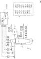
- FIG. 1 shows a gasifier for gasification of coal and a control unit configured to execute the method according to the invention.
- the gasifier 14 comprises a burner 6, a gasification reactor 7 and a slag flow discharge 8 for the removal of ash residues from the gasification process.
- the gasifier is further equipped with a cooling system 15 through which cooling water flows for abating the temperature of the gasifier 14 in the gasification reactor 7.
- the cooling system 15 of the gasifier 14 is fluidly in connection with a steam drum 9 for the steam generated through cooling of the gasification process.
- the steam drum 9 is fluidly connected to a cooling water feeding line 16 which provides boiler feed water for usage as the cooling water in the cooling system 15.
- the generated steam is discharged from the process via steam line 10 and may be used as export steam.
- the gasifier is further equipped with three separate coal feeding lines 1, 2 and 3, one oxygen feeding line 4 and one steam feeding line 5.
- the coal feeding lines and the gasification reactor are under elevated pressure, for example at a pressure between 30 and 40 bar.
- Coal, oxygen and steam enter the gasifier 14 via the burner 6 and are gasified under partial oxidation conditions in the gasification reactor 7 to produce synthesis gas as the desired combustible product gas.
- the produced synthesis gas which is sent via synthesis gas line 11 to a downstream unit (not shown) may contain undesired side products such as carbon dioxide and methane.
- the three coal feeding lines 1,2 and 3, the oxygen feeding line 4 and the steam feeding line 5 are equipped with control valves.
- the control unit of the gasifier comprises a multivariate model predictive controller (MMPC) 13, which comprises a plurality of dynamic models (referred to as “dynamic models"), an optimizer and a controller (controller not shown).
- MMPC multivariate model predictive controller
- the control valves of the feeding lines 1-5 can receive and execute desired control and regulation actions from the MMPC in the form of calculated manipulated variable data received from the MMPC.
- the control unit of the gasifier further comprises a plurality of flow controllers, indicators and analyzers which are listed in the following table.
- Ref. No. Description FIC 1 Coal Line 1 Flow Controller FIC 2 Coal Line 2 Flow Controller FIC 3 Coal Line 3 Flow Controller FIC 4 Oxygen Flow Controller FIC 5 Steam Flow Controller FI 1 Generated Steam Flow Indicator PD 2 Generated Steam Density Indicator TI 1 Gasifier Wall Temperature Indicator PI 1 Gasifier Pressure Indicator DP 1 Gasifier Pressure Difference Indicator FI 2 Output Syngas Flow Indicator TI 2 Output Syngas Temperature Indicator PI 2 Output Syngas Pressure Indicator QI 1 Analyzer for CO 2 Concentration in Output Syngas QI 2 Analyzer for CH 4 Concentration in Output Syngas QI 3 Analyzer for CO Concentration in Output Syngas QI 4 Analyzer for H 2 Concentration in Output Syngas
- Coal line controllers FIC 1, FIC 2 and FIC 3 control the coal flow in coal feeding lines 1-3.
- the value of the coal flow in coal feeding lines 1-3 is represented by manipulating variables MV 1, MV 2 and MV 3 which are regulated and controlled by the controller of the MMPV 13, based on calculations performed by the dynamic models and optimizer of the MMPV 13.
- Oxygen flow controller FIC 4 controls the oxygen flow in oxygen feeding line 4.
- the value of the oxygen flow in oxygen feeding line 4 is represented by manipulating variable MV 4, which is again regulated and controlled by the controller of the MMPV 13, based on calculations performed by the dynamic models and optimizer of the MMPV 13.
- Steam flow controller FIC 5 controls the steam flow in steam feeding line 5.
- the value of the steam flow in steam feeding line 5 is represented by manipulating variable MV 5, which is again regulated and controlled by the controller of the MMPV 13, based on calculations performed by the dynamic models and optimizer of the MMPV 13.
- the generated steam flow indicator FI 1 and the generated steam density indicator PD 2 measure the steam flow and the steam density of steam line 10.
- the flow of cooling water in the cooling water feeding line 16 and the cooling system 15 is fixed, the steam flow and the steam density in steam line 10 varies due to temperature fluctuations in the gasification reactor 7. Therefore, variations of the steam flow measured by steam flow indicator FI 1 and variations of the steam density measured by steam density indicator PD 2 are indicators for temperature fluctuations in the gasification reactor 7.
- steam density and steam flow represent disturbance variables (DVs) of the process.
- the wall temperature of the gasifier is measured by gasifier wall temperature indicator TI 1.
- the gasifier wall temperature shall be kept within a controlled range, e.g. for safety reasons and controllability of the gasification reaction, and therefore represents a controlled variable (CV) of the process.
- the pressure in the gasification reactor 7 is measured by gasifier pressure indicator PI 1.
- the gasifier pressure shall be kept within a controlled range, e.g. for safety reasons and controllability of the gasification reaction. Since it is determined by downstream operation, e.g. pressure drops, it represents a disturbing variable (DV) of the gasification process.
- syngas pressure in synthesis gas line 11 is measured by output syngas pressure indicator PI 2.
- the syngas temperature in synthesis gas line 11 is measured by output syngas temperature indicator TI 2.
- Syngas pressure and syngas temperature are parameters that are not intended to be changed or controlled. Therefore, syngas temperature and pressure represent process output variables (POVs) of the process.
- the syngas flow in synthesis gas line 11 is measured by the output syngas flow indicator FI 2.
- the syngas flow indicates the effective syngas production (determined in Nm3/h, i.e. normalized to standard temperature and pressure). Since the effective syngas production is crucial for the effectiveness of the gasification process, it represents a controlled variable (CV) of the process.
- the effective syngas production may be calculated directly from the wet syngas flow, and process output variables (POVs) including the syngas temperature and pressure, and the hydrogen and carbon monoxide concentrations in the syngas.
- the concentration of carbon dioxide (CO 2 ) in the syngas of synthesis gas line 11 is measured by the analyzer for CO 2 concentration in output syngas QI 1.
- the concentration of methane (CH 4 ) in the syngas of synthesis gas line 11 is measured by the analyzer for CH 4 concentration in output syngas QI 2.
- Carbon dioxide and methane are undesired products of the gasification reaction. Therefore, the concentrations of carbon dioxide and methane in the synthesis gas shall be kept within a controlled range, e.g. between a pre-defined acceptable lower and upper limit.
- the concentrations of carbon dioxide and methane represent controlled variables (CVs) of the process accordingly.
- the concentration of carbon monoxide (CO) in the syngas of synthesis gas line 11 is measured by the analyzer for CO concentration in output syngas QI 3.
- the concentration of hydrogen (H 2 ) in the syngas of synthesis gas line 11 is measured by the analyzer for H 2 concentration in output syngas QI 4.
- the ratio between hydrogen and carbon monoxide in the synthesis gas depends on the carbon- and hydrogen-content of the feedstock (fuel), which is used in the gasification reaction, and gasifier operating conditions, e.g. temperature and pressure. Since this ratio is governed by complex chemical equilibrium reactions, this ratio cannot be used by process regulation and control measures. Therefore, concentrations of carbon monoxide and hydrogen represent process output variables (POVs) of the process accordingly.
- POVs process output variables
- the data of the various flow controllers, indicators and analyzers mentioned before is collected in real time in data acquisition and recording system 12.
- the data acquisition and recording system 12 is either a programmable logic controller (PLC) or a distributed control system (DCS).
- PLC programmable logic controller
- DCS distributed control system
- the data acquired and recorded in system 12, which represents the CVs, DVs and POVs of the process, is transferred to the multivariate model predictive controller (MMPV) 13.
- the MMPV may calculate intermediate variable (IV) data based on the input data from CVs, DVs and POVs in case a combined effect between at least two of the aforementioned variable types exists.
- the dynamic models and the optimizer calculate how the MVs MV 1, MV2, MV3, MV4 and MV 5 have to be changed to minimize a deviation of a current CV of the process from the set point of the respective CV. This is done in an iterative process of calculations within a set prediction and control horizon as described in detail before.
- the optimal value for each of the MV1, MV2, MV3, MV4 and MV5 is set, i.e. actuated by the controller of the MMPV, which regulates and controls the control valves of the feeding lines 1 to 5.
- the outputs of the MMPC are the new MV set points for the three coal feeding lines 1 to 3, the oxygen feeding line 4 and the steam feeding line 5.
- the control valves over each feeding line regulate the corresponding flow to reach the received set point from the MMPC.
- the control and operation of the gasifier is kept under optimal conditions. For instance, the methane and carbon dioxide concentration in the synthesis gas is kept at a minimum.
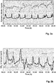
- Fig. 2a shows an example for two different dynamic model input variables and how their values change over a period of 8 hours.
- the bold line shows the change in pressure difference between the feeding tank for the carbonaceous fuel (coal) and the gasifier, which may be measured in kPa. This pressure difference is assigned as a disturbance variable (DV) for the development of a dynamic model.
- the thin line shows the change in the ratio of the mass of a gasifying agent (oxygen) and the mass of the carbonaceous fuel (coal). This ratio is assigned as an intermediate variable (IV) for the development of the dynamic model, as it is a combination of two basic variables.
- the pressure difference peaks cause changes in the formation of methane, which in turn is an indicator for temperature changes in the gasifier.
- the thin line of Fig. 2b shows real measured data of the methane concentration in ppm.
- the bold line of Fig. 2b shows data calculated, i.e. predicted by the developed dynamic model on basis of a closed loop system identification approach.
- Figures 3a, 3b , 4a and 4b demonstrate the operation of the gasifier with and without implementation of the solution according to the inventive method.
- the MMPC In the first 6 hours of simulation the MMPC is off and the shown data is solely real operational data taken from the distributed control system (DCS) of the data acquisition and recording system.
- DCS distributed control system
- the MMPC solution is turned on with the primary focus of stabilizing the operation with regard to ratio of oxygen to total coal (intermediate variable), CH 4 concentration in the synthesis gas (controlled variable) and the effective syngas production (controlled variable).
- the constraints of maximization of produced effective syngas is applied ( Fig. 4b ).
- signals for DVs were taken from real operational data and were fed as feed forward signals ( Fig. 4a ).
- the fluctuations in the ratio of oxygen to total coal have been mitigated by around 80% which corresponds to tighter and smoother control actions over available MVs related to oxygen and coal input flows.
- Real operational data in Figures 3a, 3b and 4b after the first 18 hours of operation reflect suboptimal operation and control actions.
- the effect of deviation from the optimal ratio of oxygen to total coal set point can be traced in a higher concentration of CH 4 in the produced synthesis gas for a long period ( Fig. 3b ).
- the higher CH 4 concentration corresponds to low temperature operation of the gasifier, which is in turn leading to inefficiency and reduced conversion.
- Such deviations from optimal operational window coupled with high bandwidth of unmitigated fluctuations have resulted in highly oscillating and reduced amounts of effective produced syngas, which can be seen in Fig. 4b .
- the developed MMPC solution delivers on average more than 1 % savings on oxygen input per unit effective syngas production (Nm 3 O 2 / Nm 3 effective syngas) as well as up to 3 % savings in total coal input per unit effective syngas production (kg coal / Nm 3 effective syngas).
- Embodiments of the invention are described with reference to different types of subject-matter.
- certain embodiments are described with reference to method claims while other embodiments are described with reference to apparatus claims.
- a person skilled in the art will infer from the description above and that which follows that, unless stated otherwise, in addition to any combination of features that belong to one type of claim, any combination between features in relation to different types of subject-matter or types of claim may also be considered. All features may be combined to achieve synergistic effects which go beyond simple summation of the technical features.
Landscapes
- Engineering & Computer Science (AREA)
- Health & Medical Sciences (AREA)
- Artificial Intelligence (AREA)
- Computer Vision & Pattern Recognition (AREA)
- Evolutionary Computation (AREA)
- Medical Informatics (AREA)
- Software Systems (AREA)
- Physics & Mathematics (AREA)
- General Physics & Mathematics (AREA)
- Automation & Control Theory (AREA)
- Industrial Gases (AREA)
Abstract
The invention relates to a method to control a gasifier, wherein the gasifier is configured for the conversion of a carbonaceous fuel to a combustible product gas. The method comprises determining a plurality of operating parameters of the gasifier and recording the determined operating parameters in a data acquisition and recording system; selecting at least one of the determined operating parameters of the gasifier as a controlled variable (CV), and at least one of the determined operating parameters of the gasifier as a manipulated variable (MV); transferring the data of the CV and of the MV to a multivariate model predictive controller (MMPC), the MMPC comprising an optimizer, a dynamic model and a controller; minimizing a deviation between a current value of the CV and a set point of the CV by calculating a sequence of predictions of the CV by means of the dynamic model, on the basis of a sequence of calculated values of the MV by means of the optimizer, in an iterative process within a set prediction time horizon and set control horizon, wherein in the iterative process, the optimizer provides the sequence of calculated values of the MV to the dynamic model, and the dynamic model provides the sequence of calculated values of the CV to the optimizer; identifying an optimized value of the MV as a result of said iterative process and applying the optimized value of the MV to the gasifier by means of the controller. The invention further relates to a control unit for a gasifier, configured to execute the method according to the invention and to a gasifier, comprising said control unit.
Description
- The invention relates to a method to control a gasifier, a control unit for a gasifier and a gasifier comprising said control unit. The gasifier is configured for the conversion of a carbonaceous fuel to a combustible product gas, in particular a synthesis gas.
- In the gasification of carbonaceous fuels, in particular coal, the carbonaceous substance undergoes e.g. partial oxidation, if oxygen is used as the gasifying agent. Processes like partial oxidation are exothermic, leading to a high-temperature environment inside the gasifier, which permits further present gases such as carbon dioxide (CO2) and steam to react with the carbonaceous feedstock. Steam is an example for an agent which is used as a moderator of the gasification reaction. The gaseous output of the gasification reaction is a combustible product gas, in particular a synthesis gas, also referred to as syngas. The main and also desired components of the syngas are carbon monoxide (CO) and hydrogen (H2), whereby side-products such as carbon dioxide (CO2) and methane (CH4) are usually undesired components. The composition of the syngas is significantly depending on the properties of the solid or liquid carbonaceous fuel, i.e. the feedstock, as well as the gasification conditions including gasification temperature and pressure. The presence of complex chemical reactions imposes highly nonlinear interactions among relevant process parameters of the gasification process, coupled with long dynamic response times, making the operation and control of a gasifier complex and challenging. Additionally, various sources of fluctuations such as variety in feedstock properties and operational conditions cause inefficient operation of the gasifier.
- Several methods are proposed in the prior art to automate and control the carbonaceous fuel gasification processes, in particular for coal. Most commonly, a proportional-integral-derivative (PID) control is proposed for control of the gasifier. In such technique, the set point of a specific fuel, i.e. the feeding coal feed, is input manually to the PID controller to obtain the required gasifier load. Sequentially, the set point of the feeding oxygen (gasifying agent) is automatically calculated by multiplying the actual feeding flow rate and a parameter known as oxygen-to-fuel ratio, i.e. oxygen-to-coal ratio, and then is sent to the PID controller of the feeding oxygen. Afterwards, the amount of feeding steam (moderator) is calculated by multiplying the actual feeding oxygen flow rate by another parameter known as steam-to-oxygen ratio and then is sent as the set point to the PID controller of the feeding steam flow. In such methods, as disclosed in
CN 108342225 ,CN 102520736 andCN 105062569 , the minimum and maximum allowable range of feeding fuel, oxygen and steam are correlated linearly to the pressure of gasification reactor. - According to
CN 108342225 andCN 102520736 , the proposed solution is based on a manual regulation of feeding coal flow based on required gasifier control and setting the feeding oxygen and steam by cascaded PID controllers using fixed oxygen-to-coal and steam-to-oxygen ratios. Since this method is a combination of manual and PID regulations, there are strong fluctuations expected in the operation like temperature and syngas yield fluctuations. Additionally, the changes are only made based on load and gasifier pressure, which do not fully describe the gasifier conditions like temperature, gas quality and conversion. This can lead to safety issues like temperature trips and inefficient operation due to low carbon conversion. -
CN 209674253 proposes to utilize temperature measurements of the gasifier wall installed in different sections of the gasifier, coupled with a programmable controller. The programmable controller is used to keep the gasification temperature in a controlled range. As the measurements of the wall temperature of the gasifier are not accurate enough to be directly used in gasification control, this solution proposes that the temperature measurements are corrected via a model. However it is not disclosed how the temperature measurements should be modified and corrected for further use in the controller. Furthermore, it is well known from operation of coal gasifiers that slag build-up due to changing composition of the coal feedstock can cause contradicting trends of temperature evolution for the same operation parameters. Additionally, the method does not reveal how a controller should be set up and which variables are to be used for maintaining the control of a gasifier based on the corrected temperature measurement. -
CN 105955020 suggests a coupling of dynamic matrix control (DMC) and PID control as combined DMC-PID control to improve the operation and control of a coal-water slurry gasification. In the DMC part of the method, the gasification reactor temperature is used as well as the carbon monoxide (CO) mole fraction of the produced syngas as controlled variables (CVs) to adjust the feeding oxygen flow and coal water slurry flow as manipulated variables (MVs) of the process. The adjustments in feeding oxygen flow and coal water slurry flow as the output of the DMC part are cascaded to PID controllers of the feeding oxygen flow (gasifying agent), feeding coal flow (feedstock), feeding water flow (moderator), oxygen-to-coal ratio controller and water-to-coal ratio controller to adjust the feed oxygen flow rate, the dry feed coal flow rate, the pumped coal water slurry flow rate and the feeding water flow rate to be mixed with dry coal. Additionally, the temperature of the gasification reactor and cooling chamber are controlled via cascaded PID control by adjusting the cooling water flow rate and oxygen-to-coal ratio. First order dynamic models are used therein to calculate the dynamic responses between MVs and CVs in the DMC part. This should overcome the problems caused by the use of a PID control of the gasification process. As the outputs of DMC part are cascaded with PID controllers, this solution is complex. Furthermore, in this solution only the gasifier temperature and the CO mole fraction of the syngas are used to regulate the feeding oxygen and coal-water slurry flows. However, in gasification, the gasifier temperature features long delay and is most often masked by other phenomena like coal slag. As coal-water slurry gasifiers use refractory lining, temperature measurements are biased by the state of degradation of the gasifier wall and are therefore highly unreliable. Also, using only CO mole fraction in syngas does not provide any information about the syngas yield and is specific to coal-water slurry systems. Therefore, this solution cannot control and optimize the effective syngas production. Moreover, this solution does not consider any disturbance variable and does not offer any solution for mitigating the fluctuations in operation caused by fluctuations in feedstock properties and gasification condition, thus it is incapable of rejecting disturbances of the gasification process effectively. - Hence, solutions have been proposed for better automation and control of coal gasification processes. However, most of the proposed solutions do not involve a combination of current relevant information of the gasifier conditions for predicting the future state of gasifier conditions, therefore taking proper control actions. Additionally, calculated parameters like feeding oxygen-to-coal ratio and feeding steam-to-oxygen ratio are fixed, although these quantities are depending on the feedstock properties, conveying gas properties and the like. So they should be regulated accordingly for the optimum control of the gasifier. Moreover, none of the proposed solutions addresses the problem of fluctuations in gasifier operation condition and disturbance rejection.
- It is thus an object of the present invention to at least partly overcome the disadvantages of the prior art.
- It is a further object of the present invention to provide a method that enables improved controllability of a gasifier.
- It is a further object of the present invention to increase the efficiency of the gasification process. In particular, it is an object of the present invention to increase the efficiency of the gasification process based on improved controllability of the gasifier.
- It is a further object of the present invention to improve the yield of combustible product gas of the gasification process and at the same time minimize the formation of undesirable by-products.
- A contribution to the at least partial solution of at least one of the above mentioned objects is provided by the subject-matter of the independent claims. The dependent claims provide preferred embodiments which contribute to the at least partial solution of at least one of the objects. Preferred embodiments of elements of a category according to the invention shall, if applicable, also be preferred for components of same or corresponding elements of a respective other category according to the invention.
- The terms "having", "comprising" or "containing" etc. do not exclude the possibility that further elements, ingredients etc. may be comprised. The indefinite article "a" or "an" does not exclude that a plurality may be present.
- The aforementioned objects are at least partly achieved by a method to control a gasifier, the gasifier being configured for the conversion of a carbonaceous fuel to a combustible product gas, the method comprising
- (a) Determining a plurality of operating parameters of the gasifier and recording the determined operating parameters in a data acquisition and recording system;
- (b) Selecting at least one of the determined operating parameters of the gasifier as a controlled variable (CV), and at least one of the determined operating parameters of the gasifier as a manipulated variable (MV);
- (c) Transferring the data of the CV and of the MV to a multivariate model predictive controller (MMPC), the MMPC comprising an optimizer, a dynamic model and a controller;
- (d) Minimizing a deviation between a current value of the CV and a set point of the CV by calculating a sequence of predictions of the CV by means of the dynamic model, on the basis of a sequence of calculated values of the MV by means of the optimizer, in an iterative process within a set prediction time horizon and set control horizon, wherein in the iterative process, the optimizer provides the sequence of calculated values of the MV to the dynamic model, and the dynamic model provides the sequence of calculated values of the CV to the optimizer;
- (e) Identifying an optimized value of the MV as a result of said iterative process and applying the optimized value of the MV to the gasifier by means of the controller.
- According to the invention, a solution is provided which comprises the development and implementation of a multivariate model predictive controller (MMPC) scheme for control of a gasification process. The MMPC controls and optimizes the operation of the gasifier. The MMPC comprises an optimizer, the actual dynamic model or a plurality of dynamic models, and a controller.
- As the optimizer is involved in minimizing a deviation between a current value of the CV and a set point of the CV by means of said iterative process, the optimizer may also be referred to as a "minimizer".
- A dynamic model is developed prior to its application within the MMPC scheme according to step (d), e.g. by combining gasification process know-how with advanced process control know-how. In the development phase of the dynamic model, sources of disturbance may be identified which e.g. result from fluctuations in the quality of the carbonaceous fuel (analysis data of the feedstock) or oscillations resulting from specific operational circumstances such as blow-off cycles or steam pressure fluctuations.
- Furthermore, for developing the dynamic model, different kinds of operating parameters are identified and assigned to different kinds of variable types, including but not limited to manipulated variables (MV), controlled variables (CVs), intermediate variables (IVs), process output variables (POVs), and disturbance variables (DVs). A mathematical dynamic model is then developed which explains the relationship between a CV as an intended model output variable and possible model inputs including different sets of MVs, IVs and DVs or combinations thereof. For each variable set, an operational range may be defined, i.e. an allowable minimum and maximum value. Furthermore, an allowable rate of change each of the defined variable sets may be defined. Afterwards, the derived dynamic model is formulated between the operational variable sets in the format of a mathematical optimization objective function for the calculation of the best operational changes and regulations in order to control the gasifier under optimal conditions.
- For applying the developed dynamic model in the inventive method to control a gasifier, a plurality of operating parameters of the gasifier is first determined and the determined operating parameters are recorded in a data acquisition and recording system according to a first method step (a). An operating parameter of the gasifier may be any parameter which can either be set as an input process parameter or which can be measured during operation of the gasifier as an output process parameter. The data acquisition and recording system may either be a programmable logic controller (PLC) or a distributed control system (DCS), without being limited to these types.
- According to a second method step (b), at least one of the determined operating parameters of the gasifier is selected as a controlled variable (CV), and at least one of the determined operating parameters of the gasifier is selected as a manipulated variable (MV).
- Controlled variables (CVs) are variables that are desired to be kept in a specific condition. Such a specific condition may be keeping the CV between a lower and an upper limit, keeping the CV close to the set point or keeping the CV at the set point. In other words, it is the objective of the control process to keep a determined operating parameter, which is selected as a CV, in a specific pre-defined condition. According to an example, the methane (CH4) concentration in the combustible product gas may be selected as a CV and shall be kept between a lower and an upper allowed methane concentration (combustible product gas is free of methane) as a lower limit.
- Manipulated variables (MVs) are variables that can be physically changed to drive the process towards desired conditions in view of the set point or set range of the CVs. In other words, it is an objective of the control process to set a manipulated variable so that the CV is within the specific pre-defined condition. Under ideal circumstances, the CV is at the desired set point. According to an example, the mass flow of the carbonaceous fuel, the mass flow of a gasifying agent (e.g. oxygen or air), or the mass flow of a moderator (e.g. steam) are manipulated variables. Manipulated variables are often also referred to as "actuating variables".
- According to a third method step (c), the data of the CV and of the MV is transferred to a multivariate model predictive controller (MMPC), wherein the MMPC comprises an optimizer, a dynamic model and a controller. During the control process, the core of the optimizer and of the dynamic model are constantly in contact via sending and receiving real time data back and forth. The MMPC may be installed on a separate computer.
- According to a fourth method step (d), a deviation between a current value of the CV and a set point of the CV is minimized by calculating a sequence of predictions of the CV by means of the dynamic model or by means of a plurality of dynamic models, on the basis of a sequence of calculated values of the MV by means of the optimizer. This is done in an iterative process within a set prediction time horizon and set control horizon, wherein in the iterative process, the optimizer provides the sequence of calculated values of the MV to the dynamic model, and the dynamic model provides the sequence of calculated values of the CV to the optimizer. In other words, according to step (d), the optimizer may provide a first value of a MV which may correspond to the current value of said MV. On the basis of this first value of the MV, the dynamic model calculates a first predicted value for the CV, which deviates from the set point of the CV by a certain amount. The amount of this deviation shall be minimized. Based on the first predicted value of the CV, the optimizer proposes a second value of the MV and sends it back to the dynamic model, which in turn calculates a second predicted value for the CV. The aforementioned steps are repeated in an iterative manner over the set prediction horizon and set control horizon until the deviation of the actual CV from the set point of the CV is minimized. The prediction horizon is the time period which is used by the dynamic model for calculating the sequence of predicted values of the CV. The control horizon is the time period which is used by the optimizer to calculate the sequence of values of the MV provided to the dynamic model. The control horizon cannot outrun the prediction horizon, i.e. the time period of the control horizon is shorter than the time period of the prediction horizon.
- According to a fifth method step (e), an optimized value of the MV is identified as a result of the iterative process according to method step (d). The optimized value of the MV is applied to the gasifier by means of the controller. In other words, the MV value calculated according to the iterative process of step (d) is set by the controller and results in an optimized CV value which does not or only minimally deviate from the desired set point value of the CV.
- A preferred embodiment of the method according to the invention is characterized in that at least one of the determined operating parameters of the gasifier is selected as a disturbance variable (DV).
- According to this embodiment, the data of the selected DV is additionally transferred to the multivariate model predictive controller (MMPC) and the DV values are used in the dynamic model or plurality of dynamic models and the optimizer to minimize a deviation between a current value of the CV and a set point of the CV according to method step (d). DVs are variables that cannot be controlled or changed directly, but they may adversely affect the dynamics and the response of the gasification process. It is therefore preferred that their effect is to be cancelled via proper control actions. Identification of the sources of disturbance of the gasification process as DVs may therefore be vital for effectiveness of the application of the MMPC control scheme.
- A preferred embodiment of the method according to the invention is characterized in that at least one of the determined operating parameters of the gasifier is selected as a process output variable (POV).
- According to this embodiment, the data of the POV is additionally transferred to the multivariate model predictive controller (MMPC) and the POV values are used in the dynamic model or the plurality of dynamic models and the optimizer to minimize a deviation between a current value of the CV and a set point of the CV according to method step (d). POVs are process parameters that are not intended to be changed or controlled, but may be used for estimation or calculation of other important properties of the gasification process.
- A preferred embodiment of the method according to the invention is characterized in that at least one of the determined operating parameters of the gasifier is selected as a calculated intermediate variable (IV), wherein the IV is calculated by combining at least two different variables, said variables being selected from the list comprising a controlled variable (CV), a manipulated variable (MV), a disturbance variable (DV) and a process output variable (POV).
- According to this embodiment, the data of the IV is additionally transferred to the multivariate model predictive controller (MMPC) and the IV values are used by the dynamic model or the plurality of dynamic models and the optimizer to minimize a deviation between a current value of the CV and a set point of the CV according to method step (d). IVs are variables that may be used to model combined effects of MVs, CVs, DVs and POVs. IVs may be kept in specific boundaries or defined as a set point just as CVs. IVs are always calculated based on the values of the combined variables selected. An IV may be specifically selected in case a combination of two selected variables shows a significant combined effect on the gasification process.
- A preferred embodiment of the method according to the invention is characterized in that the controlled variable (CV) is selected from at least one element of the list comprising
- effective combustible product gas production;
- methane (CH4) concentration in the combustible product gas;
- carbon dioxide (CO2) concentration in the combustible product gas;
- a gasifier wall temperature.
- The effective combustible product gas production is the flow rate of the dry desired gas components in the combustible product gas. In an example, the effective combustible product gas production is the effective syngas production, i.e. the flow rate of dry carbon monoxide (CO) and hydrogen (H2) in the combustible product gas. It may be determined in Nm3/h. The value shall be as high as possible. Methane and carbon dioxide are usually undesired components in the combustible product gas. Their values shall be as low as possible. Furthermore, it was found that the methane concentration in the combustible product gas is a strong indicator for the temperature inside the gasifier, which cannot be measured directly. Furthermore, it was found that the carbon dioxide concentration in the combustible product gas is a strong indicator for both the temperature and the conversion inside the gasifier. The methane concentration in the combustible product gas may be determined in ppm (volume). The carbon dioxide concentration in the combustible product gas may be determined in %vol. The gasifier wall temperature may additionally represent the actual gasification temperature. Hence, it influences the gasification process in terms of combustible product gas yield and formation of undesired side products such as methane and carbon dioxide. Therefore, the gasifier wall temperature should be kept within a certain temperature range.
- A preferred embodiment of the method according to the invention is characterized in that the manipulated variable (MV) is selected from at least one element of the list comprising
- mass flow of the carbonaceous fuel;
- volumetric flow of a gasification agent;
- volumetric flow of a moderator.
- The gasification process can be controlled in an effective manner mainly by the optimal determination of the MVs by the MMPC, so that optimized CVs result. The most important MVs identified are the mass flow of the carbonaceous fuel, and the respective volumetric flows of the gasification agent and the moderator. In an example, the mass flow of the carbonaceous fuel is the mass flow of coal. Said mass flow may be determined in kg/h. In an example, the volumetric flow or flow rate of the gasification agent is the volumetric flow of Oxygen or air. It may be determined in Nm3/h. In an example, the volumetric flow of the moderator is the volumetric flow of steam. It may be determined in kg/h.
- A preferred embodiment of the method according to the invention is characterized in that the disturbance variable (DV) is selected from at least one element of the list comprising
- a pressure difference between a feeding tank comprising the carbonaceous fuel and the gasifier;
- a density of steam generated in a cooling system of a gasification reactor, wherein the gasification reactor forms part of the gasifier;
- a mass flow of steam generated in a cooling system of a gasification reactor, wherein the gasification reactor forms part of the gasifier.
- Using disturbance variables in the dynamic model of the MMPC scheme results in further improvements of the controllability of the process. The feeding tank comprising the carbonaceous fuel, e.g. coal, is fluidly connected to the gasifier. The pressure difference between the feeding tank which comprises the carbonaceous fuel and the gasifier is induced by fuel pressurization cycles in the feeding system. It causes systematic peaks in almost all mentioned operational parameter signals due to the disturbance of the carbonaceous fuel flow. In an example, the pressure difference between a feeding tank comprising the carbonaceous fuel and the gasifier is the pressure difference between a feeding tank comprising a solid carbonaceous fuel, in particular coal, and the gasifier. The pressure difference may be determined in kPa.
- The part of the gasifier in which the gasification reaction takes place may be referred to as the gasification reactor. The gasification reactor may comprise a cooling system. Several cooling systems are known in the art and may be selected from a cooling jacket, a cooling coil, a membrane wall or combinations thereof.
- The density of steam generated in a cooling system of the gasification reactor and the mass flow of steam generated in a cooling system of the gasification reactor both are dependent on the steam pressure and are sensitive to its fluctuations in the cooling system of the gasification reactor. Those steam pressure fluctuations indicate disturbances to the gasification process. Furthermore, the steam mass flow and density in the cooling system of the gasification reactor is a strong indicator for the temperature within the gasification reactor, which cannot be measured directly. When the feeding cooling water is provided with a fixed flowrate, under ideal conditions, e.g. no temperature changes in the gasification reactor, the generated steam should not change in the amount produced or its density. Steam is generated in the cooling system of the gasification reactor through the evaporation of the cooling water. The density of steam generated in the cooling system of the gasification reactor may be determined in kg/m3. The mass flow of steam generated in the cooling system of the gasification reactor may be determined in kg/h.
- A preferred embodiment of the method according to the invention is characterized in that the process output variable (POV) is selected from at least one element of the list comprising
- a volume fraction of carbon monoxide (CO) in the combustible product gas;
- a volume fraction of hydrogen (H2) in the combustible product gas;
- a pressure of the combustible product gas;
- a temperature of the combustible product gas.
- POVs are process parameters that are not intended to be changed or controlled, but are used for estimation or calculation of other important properties. The volume fractions of H2 and CO together with temperature and pressure of the combustible product gas may be used to calculate the amount of the dry combustible product gas in view of the desired components (H2 and CO). In an example, the dry combustible product gas is syngas. The volume fraction of carbon monoxide or hydrogen in the combustible product gas may be determined in %vol. The pressure of the combustible product gas may be determined in MPa. The temperature of the combustible product gas may be determined in °C.
- A preferred embodiment of the method according to the invention is characterized in that the intermediate variable (IV) is selected from at least one element of the list comprising
- a ratio of a the mass of a gasifying agent and the mass of the carbonaceous fuel;
- a ratio of a mass of a gasifying agent and the mass of a moderator;
- a first mass flow of the carbonaceous fuel and a second mass flow of the carbonaceous fuel;
- Using intermediate variables (IVs) in the dynamic model means considering combined effects of variables, which results in further improved controllability and effectiveness of the gasification process. In particular, the ratio of mass of a gasifying agent and the mass of the carbonaceous fuel, the ratio of the mass of a gasifying agent and the mass of a moderator, and a first and second mass flow of the carbonaceous fuel were determined as most important intermediate variables.
- A first and second mass flow of the carbonaceous fuel means the sum of the first and second mass flow. In an example, the sum of the first and second mass flow of the carbonaceous fuel is the total mass flow of the carbonaceous fuel. The first and second mass flows of the carbonaceous fuel may also referred to as first partial mass flow and second partial mass flow. Further mass flows or partial mass flows may be applicable, e.g. a third, fourth, fifth and/or sixth mass flow or partial mass flow. The mass flows or partial mass flows sum up to a total mass flow. Any mass flow or partial mass flow may be controlled separately. Hence, combinations of mass flows or partial mass flows are intermediate variables (IVs).
- The ratio of the mass of a gasifying agent and the mass of the carbonaceous fuel, and the ratio of the mass of a gasifying agent and the mass of a moderator may be determined in weight per weight, e.g. in kg/kg. The first mass flow of the carbonaceous fuel and the second mass flow of the carbonaceous fuel may be determined in kg/h.
- A preferred embodiment of the method according to the invention is characterized in that the dynamic model or the plurality of dynamic models uses/use at least one element selected from the list of a MV, DV, IV and POV as an input parameter, to predict a value of a CV as an output parameter for the control process.
- In order to carry out the dynamic optimization and control by the MMPC, the MMPC utilizes a dynamic model or a plurality of dynamic models of the gasification process. The input of a dynamic model for the gasifier include MVs, DVs, IVs or POVs, while the outputs are CVs. The task of the dynamic model is to calculate the dynamic response of CVs with regard to changes in MVs, DVs, IVs or POVs. For example, process time delays between process variables and responses, rate of change in different variables and the behavior of process variables while reaching towards the process steady state gains are dynamic behaviors explained and estimated via the developed dynamic model of the MMPC.
- A preferred embodiment of the method according to the invention is characterized in that in an identification phase of the dynamic model, a single MV is modelled against a related CV and/or IV.
- A further preferred embodiment of the method according to the invention is characterized in that in an identification phase of the dynamic model, a DV, POV or IV is separately modelled against its relevant CV.
- During the identification phase each single MV is modeled against related CV or IV. Further preferred, each DV, POV or IV is separately modeled versus its relevant CV.
- A preferred embodiment of the method according to the invention is characterized in that the dynamic model is identified by a closed loop system identification, an open loop system identification or a combination thereof.
- The task of developing a dynamic model is referred to as system identification. For performing an effective system identification, two approaches are conceivable with regard to the present invention. Those approaches are referred to as closed loop system identification and open loop system identification. Also a combination of both approaches is conceivable in developing the dynamic model for the MMPC control scheme.
- In closed loop system identification, available historical data from previous operation is used in the model fitting and development phase. After spotting the suitable time segments in the operational data, these segments can be used in the dynamic model development phase.
- In open loop system identification, sequential changes are applied on each MV at a time to record and collect the response of different CVs. In an example, a sequential change is a step test. After this, the collected data is used for developing the dynamic model.
- Possible dynamic models may be stored in a matrix helping to map the developed connections between control variable sets. This matrix is referred to as dynamic matrix control (DMC) and may form the basis of the MMPC scheme for process variables estimation and control actions calculations according to method step (d) of the present invention.
- The parametric transfer function models in Laplacian domain are used for dynamic modeling of the gasifier. These models can include several parameters, namely, s as the Laplacian variable, Gain as the process gain, Delay as the process time delay, τ 1 and τ 2 as the process time constants and β as the free parameter. During identification, the suitable model type and its parameters for accurate modeling is calculated. The following table presents possible models that may be used.
Model Type Equation Gain G(s) = Gain Gain Delay G(s) = Gain ∗ e -Delay∗s Gain Delay Ramp 
First Order 
First Order Ramp 
First Order Beta 
Second Order 
Second Order Ramp 
Second Order Beta 
Second Order Beta Ramp 
Zero Gain First Order 
Zero Gain Second Order 
Zero Gain Second Order Beta 
- A preferred embodiment of the method according to the invention is characterized in that the MMPC uses an optimization algorithm according to

- Si is the set point of the CV to be achieved,
- YEstimated,i is the CV predicted by the dynamic model,
- ΔUi is the change to be applied on a MV,
- wy and wu are regulating parameters which affect the aggressiveness and robustness of the optimization,
- ny is the prediction horizon and
- nu is the control horizon.
- After developing a suitable dynamic model as set out above, an optimization formulation of the dynamic control problem is being worked out. The solution of such a dynamic optimization will be the optimum changes and regulation on the MVs (inputs) to keep the gasifier under optimal control. Additionally, there are process operation and safety boundaries to be imposed as constraints upon this optimization formulation. For example, in the gasification of coal, it is desired to keep the feeding oxygen-to-coal ratio in a specific span to ensure the optimal operation and avoid safety issues. Such conditions can be formulated as constraints of the optimization formulation. In general, the aforementioned optimization algorithm may be preferably implemented for optimal control. The job of the solver is to find the best ΔUi which result in minimizing the f while satisfying the imposed constraints. The DMC (dynamic model) and optimizer core are constantly in contact via sending and receiving the real time data back and forth.
- The objects of the invention are also at least partly achieved by a control unit for a gasifier, configured to execute the method according to the invention.
- The objects of the invention are also at least partly achieved by a gasifier, comprising the aforementioned control unit.
- In one embodiment, the gasifier is configured for the conversion of a carbonaceous fuel to a combustible product gas.
- In one embodiment, the carbonaceous fuel is a solid fuel, in particular coal, and the combustible product gas is a synthesis gas. Synthesis gas is also referred to as "syngas". Instead of or additional to coal, the solid fuel may also comprise biomass, sewage sludge, refuse derived fuel and/or mineral-contaminated plastics, without being limited to the aforementioned carbonaceous fuel types.
- The carbonaceous fuel may comprise any carbon containing feedstock in solid, liquid and/or gaseous state. The solid, liquid and/or gaseous carbonaceous fuel is suitable for conversion to the combustible product gas. The conversion of the carbonaceous fuel to the combustible product gas takes place under gasification conditions. Gasification refers to any chemical conversion of a single or multiple component chemical reaction, wherein at least one of the reacting components (reactants) of the reaction is subjected to partial oxidation. The partial oxidation results in a single or multiple components product gas, in which at least one of the gaseous product components may further oxidized, i.e. is combustible. The partial oxidation may take place under the influence of oxygen or any other suitable oxidation agent.
- The invention is elucidated in detail hereinafter by an example how to carry out the invention without restricting the subject-matter of the invention. Further features, advantages and possible applications of the invention will be apparent from the following description of the execution example in conjunction with the drawings.
- The examples in the figures refer to a gasifier for the gasification of coal as an example for a solid carbonaceous fuel, to produce synthesis gas as an example for a combustible product gas.
- In the drawings,
- Figure 1
- depicts an overall scheme of a gasifier for gasification of coal and a control unit configured to execute the method according to the invention,
- Figures 2a, 2b
- depict an example of dynamic model response for the CH4 concentration in the synthesis gas as controlled (model output) variable (
Fig. 2b , in ppm), and having the ratio of O2/ total coal as an intermediate (model input) variable and the pressure difference between the coal feeding tank and the gasifier as disturbance (model input) variable (Fig. 2a ), - Figures 3a, 3b
- depict a simulation of the operation of a gasifier with and without implementation of the method according to the invention, for the ratio of O2/ total coal as intermediate (process input) variable (
Fig. 3a , in wt/wt) and CH4 concentration in the synthesis gas as controlled (process output) variable (Fig. 3b , in ppm). - Figures 4a, 4b
- depict a simulation of the pressure difference between the coal feeding tank and the gasifier during operation of a gasifier (
Fig. 4a , ΔP in kPa) and a simulation of the effective synthesis gas production as a controlled (process output) variable with and without implementation of the method according to the invention (Fig. 4b , Nm3/h). -
Figure 1 shows a gasifier for gasification of coal and a control unit configured to execute the method according to the invention. Thegasifier 14 comprises aburner 6, agasification reactor 7 and aslag flow discharge 8 for the removal of ash residues from the gasification process. The gasifier is further equipped with acooling system 15 through which cooling water flows for abating the temperature of thegasifier 14 in thegasification reactor 7. Thecooling system 15 of thegasifier 14 is fluidly in connection with asteam drum 9 for the steam generated through cooling of the gasification process. Thesteam drum 9 is fluidly connected to a coolingwater feeding line 16 which provides boiler feed water for usage as the cooling water in thecooling system 15. The generated steam is discharged from the process viasteam line 10 and may be used as export steam. - The gasifier is further equipped with three separate
coal feeding lines oxygen feeding line 4 and onesteam feeding line 5. The coal feeding lines and the gasification reactor are under elevated pressure, for example at a pressure between 30 and 40 bar. Coal, oxygen and steam enter thegasifier 14 via theburner 6 and are gasified under partial oxidation conditions in thegasification reactor 7 to produce synthesis gas as the desired combustible product gas. The produced synthesis gas, which is sent viasynthesis gas line 11 to a downstream unit (not shown) may contain undesired side products such as carbon dioxide and methane. The threecoal feeding lines oxygen feeding line 4 and thesteam feeding line 5 are equipped with control valves. - The control unit of the gasifier comprises a multivariate model predictive controller (MMPC) 13, which comprises a plurality of dynamic models (referred to as "dynamic models"), an optimizer and a controller (controller not shown). The control valves of the feeding lines 1-5 can receive and execute desired control and regulation actions from the MMPC in the form of calculated manipulated variable data received from the MMPC.
- The control unit of the gasifier further comprises a plurality of flow controllers, indicators and analyzers which are listed in the following table.
Ref. No. Description FIC 1 Coal Line 1Flow Controller FIC 2 Coal Line 2Flow Controller FIC 3 Coal Line 3Flow Controller FIC 4 Oxygen Flow Controller FIC 5 Steam Flow Controller FI 1 Generated Steam Flow Indicator PD 2 Generated Steam Density Indicator TI 1 Gasifier Wall Temperature Indicator PI 1 Gasifier Pressure Indicator DP 1 Gasifier Pressure Difference Indicator FI 2 Output Syngas Flow Indicator TI 2 Output Syngas Temperature Indicator PI 2 Output Syngas Pressure Indicator QI 1 Analyzer for CO2 Concentration in Output Syngas QI 2 Analyzer for CH4 Concentration in Output Syngas QI 3 Analyzer for CO Concentration in Output Syngas QI 4 Analyzer for H2 Concentration in Output Syngas - Coal
line controllers FIC 1,FIC 2 andFIC 3 control the coal flow in coal feeding lines 1-3. The value of the coal flow in coal feeding lines 1-3 is represented by manipulatingvariables MV 1,MV 2 andMV 3 which are regulated and controlled by the controller of theMMPV 13, based on calculations performed by the dynamic models and optimizer of theMMPV 13. Oxygenflow controller FIC 4 controls the oxygen flow inoxygen feeding line 4. The value of the oxygen flow inoxygen feeding line 4 is represented by manipulatingvariable MV 4, which is again regulated and controlled by the controller of theMMPV 13, based on calculations performed by the dynamic models and optimizer of theMMPV 13. Steamflow controller FIC 5 controls the steam flow insteam feeding line 5. The value of the steam flow insteam feeding line 5 is represented by manipulatingvariable MV 5, which is again regulated and controlled by the controller of theMMPV 13, based on calculations performed by the dynamic models and optimizer of theMMPV 13. - The generated steam
flow indicator FI 1 and the generated steamdensity indicator PD 2 measure the steam flow and the steam density ofsteam line 10. Although the flow of cooling water in the coolingwater feeding line 16 and thecooling system 15 is fixed, the steam flow and the steam density insteam line 10 varies due to temperature fluctuations in thegasification reactor 7. Therefore, variations of the steam flow measured by steamflow indicator FI 1 and variations of the steam density measured by steamdensity indicator PD 2 are indicators for temperature fluctuations in thegasification reactor 7. Hence, steam density and steam flow represent disturbance variables (DVs) of the process. - The wall temperature of the gasifier is measured by gasifier wall
temperature indicator TI 1. The gasifier wall temperature shall be kept within a controlled range, e.g. for safety reasons and controllability of the gasification reaction, and therefore represents a controlled variable (CV) of the process. - The pressure in the
gasification reactor 7 is measured by gasifierpressure indicator PI 1. The gasifier pressure shall be kept within a controlled range, e.g. for safety reasons and controllability of the gasification reaction. Since it is determined by downstream operation, e.g. pressure drops, it represents a disturbing variable (DV) of the gasification process. - The syngas pressure in
synthesis gas line 11 is measured by output syngaspressure indicator PI 2. The syngas temperature insynthesis gas line 11 is measured by output syngastemperature indicator TI 2. Syngas pressure and syngas temperature are parameters that are not intended to be changed or controlled. Therefore, syngas temperature and pressure represent process output variables (POVs) of the process. - The syngas flow in
synthesis gas line 11 is measured by the output syngasflow indicator FI 2. The syngas flow indicates the effective syngas production (determined in Nm3/h, i.e. normalized to standard temperature and pressure). Since the effective syngas production is crucial for the effectiveness of the gasification process, it represents a controlled variable (CV) of the process. The effective syngas production may be calculated directly from the wet syngas flow, and process output variables (POVs) including the syngas temperature and pressure, and the hydrogen and carbon monoxide concentrations in the syngas. - The concentration of carbon dioxide (CO2) in the syngas of
synthesis gas line 11 is measured by the analyzer for CO2 concentration inoutput syngas QI 1. The concentration of methane (CH4) in the syngas ofsynthesis gas line 11 is measured by the analyzer for CH4 concentration inoutput syngas QI 2. Carbon dioxide and methane are undesired products of the gasification reaction. Therefore, the concentrations of carbon dioxide and methane in the synthesis gas shall be kept within a controlled range, e.g. between a pre-defined acceptable lower and upper limit. The concentrations of carbon dioxide and methane represent controlled variables (CVs) of the process accordingly. - The concentration of carbon monoxide (CO) in the syngas of
synthesis gas line 11 is measured by the analyzer for CO concentration inoutput syngas QI 3. The concentration of hydrogen (H2) in the syngas ofsynthesis gas line 11 is measured by the analyzer for H2 concentration inoutput syngas QI 4. The ratio between hydrogen and carbon monoxide in the synthesis gas depends on the carbon- and hydrogen-content of the feedstock (fuel), which is used in the gasification reaction, and gasifier operating conditions, e.g. temperature and pressure. Since this ratio is governed by complex chemical equilibrium reactions, this ratio cannot be used by process regulation and control measures. Therefore, concentrations of carbon monoxide and hydrogen represent process output variables (POVs) of the process accordingly. - The data of the various flow controllers, indicators and analyzers mentioned before is collected in real time in data acquisition and
recording system 12. The data acquisition andrecording system 12 is either a programmable logic controller (PLC) or a distributed control system (DCS). The data acquired and recorded insystem 12, which represents the CVs, DVs and POVs of the process, is transferred to the multivariate model predictive controller (MMPV) 13. The MMPV may calculate intermediate variable (IV) data based on the input data from CVs, DVs and POVs in case a combined effect between at least two of the aforementioned variable types exists. On basis of the different CVs, DVs, POVs and IDs acquired, recorded and calculated, the dynamic models and the optimizer calculate how theMVs MV 1, MV2, MV3, MV4 andMV 5 have to be changed to minimize a deviation of a current CV of the process from the set point of the respective CV. This is done in an iterative process of calculations within a set prediction and control horizon as described in detail before. The optimal value for each of the MV1, MV2, MV3, MV4 and MV5 is set, i.e. actuated by the controller of the MMPV, which regulates and controls the control valves of thefeeding lines 1 to 5. In other words, the outputs of the MMPC are the new MV set points for the threecoal feeding lines 1 to 3, theoxygen feeding line 4 and thesteam feeding line 5. Sequentially, the control valves over each feeding line regulate the corresponding flow to reach the received set point from the MMPC. Via iterating over the aforementioned inventive procedure, the control and operation of the gasifier is kept under optimal conditions. For instance, the methane and carbon dioxide concentration in the synthesis gas is kept at a minimum. -
Fig. 2a shows an example for two different dynamic model input variables and how their values change over a period of 8 hours. The bold line shows the change in pressure difference between the feeding tank for the carbonaceous fuel (coal) and the gasifier, which may be measured in kPa. This pressure difference is assigned as a disturbance variable (DV) for the development of a dynamic model. The thin line shows the change in the ratio of the mass of a gasifying agent (oxygen) and the mass of the carbonaceous fuel (coal). This ratio is assigned as an intermediate variable (IV) for the development of the dynamic model, as it is a combination of two basic variables. AsFigure 2b shows, in particular the pressure difference peaks cause changes in the formation of methane, which in turn is an indicator for temperature changes in the gasifier. The thin line ofFig. 2b shows real measured data of the methane concentration in ppm. The bold line ofFig. 2b shows data calculated, i.e. predicted by the developed dynamic model on basis of a closed loop system identification approach. - The implementation of the method according to the invention was simulated to demonstrate its ability to deliver the mentioned benefits.
Figures 3a, 3b ,4a and 4b demonstrate the operation of the gasifier with and without implementation of the solution according to the inventive method. - In the first 6 hours of simulation the MMPC is off and the shown data is solely real operational data taken from the distributed control system (DCS) of the data acquisition and recording system. After about 6 hours, the MMPC solution is turned on with the primary focus of stabilizing the operation with regard to ratio of oxygen to total coal (intermediate variable), CH4 concentration in the synthesis gas (controlled variable) and the effective syngas production (controlled variable). After 10 hours of stable operation, when the stability is ensured, the constraints of maximization of produced effective syngas is applied (
Fig. 4b ). During the overall simulation, signals for DVs were taken from real operational data and were fed as feed forward signals (Fig. 4a ). As it can be seen inFig. 3a , after turning the MMPC on, the fluctuations in the ratio of oxygen to total coal have been mitigated by around 80% which corresponds to tighter and smoother control actions over available MVs related to oxygen and coal input flows. - Real operational data in
Figures 3a, 3b and4b after the first 18 hours of operation reflect suboptimal operation and control actions. The effect of deviation from the optimal ratio of oxygen to total coal set point (seen inFig. 3a ) can be traced in a higher concentration of CH4 in the produced synthesis gas for a long period (Fig. 3b ). The higher CH4 concentration corresponds to low temperature operation of the gasifier, which is in turn leading to inefficiency and reduced conversion. Such deviations from optimal operational window coupled with high bandwidth of unmitigated fluctuations have resulted in highly oscillating and reduced amounts of effective produced syngas, which can be seen inFig. 4b . For operation with MMPC on during the same time period, a stable and smooth operation for the ratio of oxygen to total coal around an optimum calculated set point is observed while continuously mitigating the effects of fluctuations (Fig. 3a ). As it is seen inFig. 3b , this can lead to lowered and tightly controlled amounts of CH4 slip in syngas translating to hot gasifier operation and high conversions. Finally, the result of this optimal control and operation can be observed inFig. 4b , where the amount of effective syngas production is kept at a constant and stable maximum of output while ensuring both operation safety and efficiency. - Furthermore, it was calculated that the developed MMPC solution delivers on average more than 1 % savings on oxygen input per unit effective syngas production (Nm3 O2 / Nm3 effective syngas) as well as up to 3 % savings in total coal input per unit effective syngas production (kg coal / Nm3 effective syngas). These savings present a significant opportunity for reduction of both direct and indirect CO2 emissions related to the gasification process.
- Embodiments of the invention are described with reference to different types of subject-matter. In particular, certain embodiments are described with reference to method claims while other embodiments are described with reference to apparatus claims. However, a person skilled in the art will infer from the description above and that which follows that, unless stated otherwise, in addition to any combination of features that belong to one type of claim, any combination between features in relation to different types of subject-matter or types of claim may also be considered. All features may be combined to achieve synergistic effects which go beyond simple summation of the technical features.
- While the invention has been represented and described in detail in the drawings and the preceding description, such a representation and description shall be considered to be illustrative or exemplary and non-limiting. The invention is not limited to the disclosed embodiments. Other variations of the disclosed embodiments may be understood and executed by those skilled in the art of the field of the claimed invention from a study of the drawing, the disclosure and the dependent claims.
-
- 1
- coal feeding line
- 2
- coal feeding line
- 3
- coal feeding line
- 4
- oxygen feeding line
- 5
- steam feeding line
- 6
- burner
- 7
- gasification reactor
- 8
- slag flow discharge
- 9
- steam drum
- 10
- steam line
- 11
- synthesis gas line
- 12
- data acquisition and recording system
- 13
- multivariate model predictive controller (MMPV)
- 14
- gasifier
- 15
- cooling system
- 16
- cooling water feeding line
-
FIC 1 -
Coal Line 1 Flow Controller -
FIC 2 -
Coal Line 2 Flow Controller -
FIC 3 -
Coal Line 3 Flow Controller -
FIC 4 - Oxygen Flow Controller
-
FIC 5 - Steam Flow Controller
-
FI 1 - Generated Steam Flow Indicator
-
PD 2 - Generated Steam Density Indicator
-
TI 1 - Gasifier Wall Temperature Indicator
-
PI 1 - Gasifier Pressure Indicator
-
DP 1 - Gasifier Pressure Difference Indicator
-
FI 2 - Output Syngas Flow Indicator
-
TI 2 - Output Syngas Temperature Indicator
-
PI 2 - Output Syngas Pressure Indicator
-
QI 1 - Analyzer for CO2 Concentration in Output Syngas
-
QI 2 - Analyzer for CH4 Concentration in Output Syngas
-
QI 3 - Analyzer for CO Concentration in Output Syngas
-
QI 4 - Analyzer for H2 Concentration in Output Syngas
Claims (18)
- Method to control a gasifier, the gasifier being configured for the conversion of a carbonaceous fuel to a combustible product gas, the method comprising(a) Determining a plurality of operating parameters of the gasifier and recording the determined operating parameters in a data acquisition and recording system;(b) Selecting at least one of the determined operating parameters of the gasifier as a controlled variable (CV), and at least one of the determined operating parameters of the gasifier as a manipulated variable (MV);(c) Transferring the data of the CV and of the MV to a multivariate model predictive controller (MMPC), the MMPC comprising an optimizer, a dynamic model and a controller;(d) Minimizing a deviation between a current value of the CV and a set point of the CV by calculating a sequence of predictions of the CV by means of the dynamic model, on the basis of a sequence of calculated values of the MV by means of the optimizer, in an iterative process within a set prediction time horizon and set control horizon, wherein in the iterative process, the optimizer provides the sequence of calculated values of the MV to the dynamic model, and the dynamic model provides the sequence of calculated values of the CV to the optimizer;(e) Identifying an optimized value of the MV as a result of said iterative process and applying the optimized value of the MV to the gasifier by means of the controller.
- The method according to claim 1, wherein at least one of the determined operating parameters of the gasifier is selected as a disturbance variable (DV).
- The method according to claim 1 or 2, wherein at least one of the determined operating parameters of the gasifier is selected as a process output variable (POV).
- The method according to one of the preceding claims, wherein at least one of the determined operating parameters of the gasifier is selected as a calculated intermediate variable (IV), wherein the IV is calculated by combining at least two different variables, said variables being selected from the list comprising a controlled variable (CV), a manipulated variable (MV), a disturbance variable (DV) and a process output variable (POV).
- The method according to one of the preceding claims, wherein the controlled variable (CV) is selected from at least one element of the list comprising- effective combustible product gas production;- methane (CH4) concentration in the combustible product gas;- carbon dioxide (CO2) concentration in the combustible product gas;- a gasifier wall temperature.
- The method according to one of the preceding claims, wherein the manipulated variable (MV) is selected from at least one element of the list comprising- mass flow of the carbonaceous fuel;- volumetric flow of a gasification agent;- volumetric flow of a moderator.
- The method according to one of the claims 2 to 6, wherein the disturbance variable (DV) is selected from at least one element of the list comprising- a pressure difference between a feeding tank comprising the carbonaceous fuel and the gasifier;- a density of steam generated in a cooling system of a gasification reactor, wherein the gasification reactor forms part of the gasifier;- a mass flow of steam generated in a cooling system of a gasification reactor, wherein the gasification reactor forms part of the gasifier.
- The method according to one of claims 3 to 7, wherein the process output variable (POV) is selected from at least one element of the list comprising- a volume fraction of carbon monoxide (CO) in the combustible product gas;- a volume fraction of hydrogen (H2) in the combustible product gas;- a pressure of the combustible product gas;- a temperature of the combustible product gas.
- The method according to one of the claims 4 to 8, wherein the intermediate variable (IV) is selected from at least one element of the list comprising- a ratio of a the mass of a gasifying agent and the mass of the carbonaceous fuel;- a ratio of a mass of a gasifying agent and the mass of a moderator;- a first mass flow of the carbonaceous fuel and a second mass flow of the carbonaceous fuel;
- The method according to one of the preceding claims, wherein the dynamic model uses at least one element selected from the list of a MV, DV, IV and POV as an input parameter, to predict a value of a CV as an output parameter for the control process.
- The method according to one of the preceding claims, wherein in an identification phase of the dynamic model, a single MV is modelled against a related CV and/or IV.
- The method according to one of the preceding claims, wherein in an identification phase of the dynamic model, a DV, POV or IV is separately modelled against its relevant CV.
- The method according to claim 11 or 12, wherein the dynamic model is identified by a closed loop system identification, an open loop system identification or a combination thereof.
- The method according to one of the preceding claims, wherein the MMPC uses an optimization algorithm according to
 Si is the set point of the CV to be achieved,YEstimated,i is the CV predicted by the dynamic model,ΔUi is the change to be applied on a MV,wy and wu are regulating parameters which affect the aggressiveness and robustness of the optimization,ny is the prediction horizon andnu is the control horizon.
 - A control unit for a gasifier, configured to execute the method according to one of the preceding claims.
- A gasifier, comprising the control unit according to claim 15.
- The gasifier according to claim 16, wherein in the gasifier is configured for the conversion of a carbonaceous fuel to a combustible product gas.
- The gasifier of claim 16, wherein the carbonaceous fuel is a solid fuel, in particular coal, and the combustible product gas is synthesis gas.
Priority Applications (1)
| Application Number | Priority Date | Filing Date | Title |
|---|---|---|---|
| EP20020223.2A EP3910428A1 (en) | 2020-05-15 | 2020-05-15 | Method to control a gasifier by means of a multivariate model predictive controller |
Applications Claiming Priority (1)
| Application Number | Priority Date | Filing Date | Title |
|---|---|---|---|
| EP20020223.2A EP3910428A1 (en) | 2020-05-15 | 2020-05-15 | Method to control a gasifier by means of a multivariate model predictive controller |
Publications (1)
| Publication Number | Publication Date |
|---|---|
| EP3910428A1 true EP3910428A1 (en) | 2021-11-17 |
Family
ID=70740392
Family Applications (1)
| Application Number | Title | Priority Date | Filing Date |
|---|---|---|---|
| EP20020223.2A Withdrawn EP3910428A1 (en) | 2020-05-15 | 2020-05-15 | Method to control a gasifier by means of a multivariate model predictive controller |
Country Status (1)
| Country | Link |
|---|---|
| EP (1) | EP3910428A1 (en) |
Cited By (3)
| Publication number | Priority date | Publication date | Assignee | Title |
|---|---|---|---|---|
| CN114694764A (en) * | 2022-04-18 | 2022-07-01 | 浙江大学 | Method for predicting hydrogen halide in multi-component organic waste high-temperature gasification furnace |
| CN116483003A (en) * | 2023-03-27 | 2023-07-25 | 万华化学集团股份有限公司 | Control method, device and equipment for the production process of coal water slurry |
| CN116697688A (en) * | 2023-06-01 | 2023-09-05 | 万华化学集团股份有限公司 | Thermal decoupling control method for cryogenic separation unit, electronic equipment and storage medium |
Citations (7)
| Publication number | Priority date | Publication date | Assignee | Title |
|---|---|---|---|---|
| GB2423831A (en) * | 2002-09-11 | 2006-09-06 | Fisher Rosemount Systems Inc | Constraint and limit feasability handling on a process control system optimizer |
| US20090222108A1 (en) * | 2008-03-03 | 2009-09-03 | Alstom Technology Ltd | Integrated controls design optimization |
| CN102520736A (en) | 2011-11-08 | 2012-06-27 | 中国华能集团清洁能源技术研究院有限公司 | Load control method of coal nozzles of dry pulverized coal gasification furnace |
| CN105062569A (en) | 2015-08-20 | 2015-11-18 | 北京雷浩环保能源技术有限公司 | Control method and system for dual fluidized bed coal gasification process load |
| CN105955020A (en) | 2016-05-03 | 2016-09-21 | 华东理工大学 | Coal water slurry gasification process DMC-PID multivariable control method |
| CN108342225A (en) | 2018-01-26 | 2018-07-31 | 山东明泉新材料科技有限公司 | Feeding control method for pulverized coal and gasifying agent |
| CN209674253U (en) | 2019-06-17 | 2019-11-22 | 中科聚信洁能热锻装备研发股份有限公司 | A kind of device of observing and controlling coal gasifier temperature |
-
2020
- 2020-05-15 EP EP20020223.2A patent/EP3910428A1/en not_active Withdrawn
Patent Citations (7)
| Publication number | Priority date | Publication date | Assignee | Title |
|---|---|---|---|---|
| GB2423831A (en) * | 2002-09-11 | 2006-09-06 | Fisher Rosemount Systems Inc | Constraint and limit feasability handling on a process control system optimizer |
| US20090222108A1 (en) * | 2008-03-03 | 2009-09-03 | Alstom Technology Ltd | Integrated controls design optimization |
| CN102520736A (en) | 2011-11-08 | 2012-06-27 | 中国华能集团清洁能源技术研究院有限公司 | Load control method of coal nozzles of dry pulverized coal gasification furnace |
| CN105062569A (en) | 2015-08-20 | 2015-11-18 | 北京雷浩环保能源技术有限公司 | Control method and system for dual fluidized bed coal gasification process load |
| CN105955020A (en) | 2016-05-03 | 2016-09-21 | 华东理工大学 | Coal water slurry gasification process DMC-PID multivariable control method |
| CN108342225A (en) | 2018-01-26 | 2018-07-31 | 山东明泉新材料科技有限公司 | Feeding control method for pulverized coal and gasifying agent |
| CN209674253U (en) | 2019-06-17 | 2019-11-22 | 中科聚信洁能热锻装备研发股份有限公司 | A kind of device of observing and controlling coal gasifier temperature |
Non-Patent Citations (1)
| Title |
|---|
| ADEODU OLUWASANMI ET AL: "On the theory of economic MPC: ELOC and approximate infinite horizon EMPC", JOURNAL OF PROCESS CONTROL, vol. 73, 30 November 2018 (2018-11-30), 30-11-2018, pages 19 - 32, XP085605206, ISSN: 0959-1524, DOI: 10.1016/J.JPROCONT.2018.09.013 * |
Cited By (3)
| Publication number | Priority date | Publication date | Assignee | Title |
|---|---|---|---|---|
| CN114694764A (en) * | 2022-04-18 | 2022-07-01 | 浙江大学 | Method for predicting hydrogen halide in multi-component organic waste high-temperature gasification furnace |
| CN116483003A (en) * | 2023-03-27 | 2023-07-25 | 万华化学集团股份有限公司 | Control method, device and equipment for the production process of coal water slurry |
| CN116697688A (en) * | 2023-06-01 | 2023-09-05 | 万华化学集团股份有限公司 | Thermal decoupling control method for cryogenic separation unit, electronic equipment and storage medium |
Similar Documents
| Publication | Publication Date | Title |
|---|---|---|
| JP5259031B2 (en) | Integrated gasification control system | |
| US8956567B2 (en) | Control and optimization system and method for chemical looping processes | |
| CA2716653C (en) | Control and optimization system | |
| JP2002524653A5 (en) | ||
| Kolbitsch et al. | Characterization of chemical looping pilot plant performance via experimental determination of solids conversion | |
| Currie et al. | Design of an air-cooled sabatier reactor for thermocatalytic hydrogenation of CO2: experimental proof-of-concept and model-based feasibility analysis | |
| Lima et al. | Modeling and simulation of water gas shift reactor: an industrial case | |
| Alarifi et al. | Multiobjective optimization of methanol synthesis loop from synthesis gas via a multibed adiabatic reactor with additional interstage CO2 quenching | |
| US20120078408A1 (en) | Advanced Control System For Steam Hydrocarbon Reforming Furnaces | |
| Zecevic et al. | Advanced operation of the steam methane reformer by using gain-scheduled model predictive control | |
| JP2012158700A (en) | Temperature control device and temperature control method | |
| Kooiman et al. | Experimental demonstration of two-stage packed bed chemical-looping combustion using syngas with CuO/Al2O3 and NiO/CaAl2O4 as oxygen carriers | |
| Krótki et al. | Advancements in CO2 hydrogenation–Investigating a CNG pilot plant in Poland | |
| Jankovic et al. | Design and implementation of a digital twin for a biomass-to-gas plant | |
| US10941361B2 (en) | Method and system for controlling soot make in synthesis gas production | |
| JPH07206401A (en) | Method for controlling hydrogen production apparatus and apparatus therefor | |
| From et al. | Understanding the dynamic interplay of CH4/CO2 ratio in electrified reforming of biogas to renewable methanol production: A pilot plant story | |
| EP4724869A1 (en) | A method of monitoring a chemical plant | |
| US11639290B2 (en) | Dry reforming of methane with carbon dioxide at elevated pressure | |
| KR101625026B1 (en) | Device for controlling the gasifier and method for controlling the gasifier using the device | |
| He et al. | Simulation of biomass gasification and application in pilot plant | |
| RU2619107C2 (en) | Fisher-tropsch synthesis | |
| CN120762462A (en) | A hydrogen-carbon ratio control method and system | |
| Pangestu et al. | Predicting Conversion and Catalyst Performance of a De-hydrogen Catalytic Reactor in Urea Plant | |
| EP4526591B1 (en) | Method of and control system for monitoring a process of circulation of solid material in a circulating fluidized bed reactor |
Legal Events
| Date | Code | Title | Description |
|---|---|---|---|
| PUAI | Public reference made under article 153(3) epc to a published international application that has entered the european phase |
Free format text: ORIGINAL CODE: 0009012 |
|
| STAA | Information on the status of an ep patent application or granted ep patent |
Free format text: STATUS: THE APPLICATION HAS BEEN PUBLISHED |
|
| AK | Designated contracting states |
Kind code of ref document: A1 Designated state(s): AL AT BE BG CH CY CZ DE DK EE ES FI FR GB GR HR HU IE IS IT LI LT LU LV MC MK MT NL NO PL PT RO RS SE SI SK SM TR |
|
| B565 | Issuance of search results under rule 164(2) epc |
Effective date: 20201012 |
|
| STAA | Information on the status of an ep patent application or granted ep patent |
Free format text: STATUS: THE APPLICATION IS DEEMED TO BE WITHDRAWN |
|
| 18D | Application deemed to be withdrawn |
Effective date: 20220518 |