EP3910372A1 - Lidar sensor unit and vehicle security system - Google Patents
Lidar sensor unit and vehicle security system Download PDFInfo
- Publication number
- EP3910372A1 EP3910372A1 EP19909042.4A EP19909042A EP3910372A1 EP 3910372 A1 EP3910372 A1 EP 3910372A1 EP 19909042 A EP19909042 A EP 19909042A EP 3910372 A1 EP3910372 A1 EP 3910372A1
- Authority
- EP
- European Patent Office
- Prior art keywords
- lidar sensor
- measurement data
- unit
- distance
- vehicle
- Prior art date
- Legal status (The legal status is an assumption and is not a legal conclusion. Google has not performed a legal analysis and makes no representation as to the accuracy of the status listed.)
- Withdrawn
Links
Images










Classifications
-
- G—PHYSICS
- G01—MEASURING; TESTING
- G01S—RADIO DIRECTION-FINDING; RADIO NAVIGATION; DETERMINING DISTANCE OR VELOCITY BY USE OF RADIO WAVES; LOCATING OR PRESENCE-DETECTING BY USE OF THE REFLECTION OR RERADIATION OF RADIO WAVES; ANALOGOUS ARRANGEMENTS USING OTHER WAVES
- G01S17/00—Systems using the reflection or reradiation of electromagnetic waves other than radio waves, e.g. lidar systems
- G01S17/02—Systems using the reflection of electromagnetic waves other than radio waves
- G01S17/06—Systems determining position data of a target
- G01S17/42—Simultaneous measurement of distance and other co-ordinates
-
- G—PHYSICS
- G01—MEASURING; TESTING
- G01S—RADIO DIRECTION-FINDING; RADIO NAVIGATION; DETERMINING DISTANCE OR VELOCITY BY USE OF RADIO WAVES; LOCATING OR PRESENCE-DETECTING BY USE OF THE REFLECTION OR RERADIATION OF RADIO WAVES; ANALOGOUS ARRANGEMENTS USING OTHER WAVES
- G01S17/00—Systems using the reflection or reradiation of electromagnetic waves other than radio waves, e.g. lidar systems
- G01S17/88—Lidar systems specially adapted for specific applications
- G01S17/93—Lidar systems specially adapted for specific applications for anti-collision purposes
- G01S17/931—Lidar systems specially adapted for specific applications for anti-collision purposes of land vehicles
-
- B—PERFORMING OPERATIONS; TRANSPORTING
- B60—VEHICLES IN GENERAL
- B60Q—ARRANGEMENT OF SIGNALLING OR LIGHTING DEVICES, THE MOUNTING OR SUPPORTING THEREOF OR CIRCUITS THEREFOR, FOR VEHICLES IN GENERAL
- B60Q1/00—Arrangement of optical signalling or lighting devices, the mounting or supporting thereof or circuits therefor
- B60Q1/0029—Spatial arrangement
- B60Q1/0041—Spatial arrangement of several lamps in relation to each other
- B60Q1/0047—Signalling unit mounted on a headlamp unit
-
- B—PERFORMING OPERATIONS; TRANSPORTING
- B60—VEHICLES IN GENERAL
- B60Q—ARRANGEMENT OF SIGNALLING OR LIGHTING DEVICES, THE MOUNTING OR SUPPORTING THEREOF OR CIRCUITS THEREFOR, FOR VEHICLES IN GENERAL
- B60Q1/00—Arrangement of optical signalling or lighting devices, the mounting or supporting thereof or circuits therefor
- B60Q1/02—Arrangement of optical signalling or lighting devices, the mounting or supporting thereof or circuits therefor the devices being primarily intended to illuminate the way ahead or to illuminate other areas of way or environments
- B60Q1/04—Arrangement of optical signalling or lighting devices, the mounting or supporting thereof or circuits therefor the devices being primarily intended to illuminate the way ahead or to illuminate other areas of way or environments the devices being headlights
-
- G—PHYSICS
- G01—MEASURING; TESTING
- G01S—RADIO DIRECTION-FINDING; RADIO NAVIGATION; DETERMINING DISTANCE OR VELOCITY BY USE OF RADIO WAVES; LOCATING OR PRESENCE-DETECTING BY USE OF THE REFLECTION OR RERADIATION OF RADIO WAVES; ANALOGOUS ARRANGEMENTS USING OTHER WAVES
- G01S7/00—Details of systems according to groups G01S13/00, G01S15/00, G01S17/00
- G01S7/48—Details of systems according to groups G01S13/00, G01S15/00, G01S17/00 of systems according to group G01S17/00
- G01S7/481—Constructional features, e.g. arrangements of optical elements
-
- G—PHYSICS
- G01—MEASURING; TESTING
- G01S—RADIO DIRECTION-FINDING; RADIO NAVIGATION; DETERMINING DISTANCE OR VELOCITY BY USE OF RADIO WAVES; LOCATING OR PRESENCE-DETECTING BY USE OF THE REFLECTION OR RERADIATION OF RADIO WAVES; ANALOGOUS ARRANGEMENTS USING OTHER WAVES
- G01S7/00—Details of systems according to groups G01S13/00, G01S15/00, G01S17/00
- G01S7/48—Details of systems according to groups G01S13/00, G01S15/00, G01S17/00 of systems according to group G01S17/00
- G01S7/481—Constructional features, e.g. arrangements of optical elements
- G01S7/4811—Constructional features, e.g. arrangements of optical elements common to transmitter and receiver
- G01S7/4813—Housing arrangements
-
- G—PHYSICS
- G01—MEASURING; TESTING
- G01S—RADIO DIRECTION-FINDING; RADIO NAVIGATION; DETERMINING DISTANCE OR VELOCITY BY USE OF RADIO WAVES; LOCATING OR PRESENCE-DETECTING BY USE OF THE REFLECTION OR RERADIATION OF RADIO WAVES; ANALOGOUS ARRANGEMENTS USING OTHER WAVES
- G01S7/00—Details of systems according to groups G01S13/00, G01S15/00, G01S17/00
- G01S7/48—Details of systems according to groups G01S13/00, G01S15/00, G01S17/00 of systems according to group G01S17/00
- G01S7/481—Constructional features, e.g. arrangements of optical elements
- G01S7/4814—Constructional features, e.g. arrangements of optical elements of transmitters alone
-
- G—PHYSICS
- G01—MEASURING; TESTING
- G01S—RADIO DIRECTION-FINDING; RADIO NAVIGATION; DETERMINING DISTANCE OR VELOCITY BY USE OF RADIO WAVES; LOCATING OR PRESENCE-DETECTING BY USE OF THE REFLECTION OR RERADIATION OF RADIO WAVES; ANALOGOUS ARRANGEMENTS USING OTHER WAVES
- G01S7/00—Details of systems according to groups G01S13/00, G01S15/00, G01S17/00
- G01S7/48—Details of systems according to groups G01S13/00, G01S15/00, G01S17/00 of systems according to group G01S17/00
- G01S7/497—Means for monitoring or calibrating
-
- G—PHYSICS
- G01—MEASURING; TESTING
- G01S—RADIO DIRECTION-FINDING; RADIO NAVIGATION; DETERMINING DISTANCE OR VELOCITY BY USE OF RADIO WAVES; LOCATING OR PRESENCE-DETECTING BY USE OF THE REFLECTION OR RERADIATION OF RADIO WAVES; ANALOGOUS ARRANGEMENTS USING OTHER WAVES
- G01S13/00—Systems using the reflection or reradiation of radio waves, e.g. radar systems; Analogous systems using reflection or reradiation of waves whose nature or wavelength is irrelevant or unspecified
- G01S13/88—Radar or analogous systems specially adapted for specific applications
- G01S13/93—Radar or analogous systems specially adapted for specific applications for anti-collision purposes
- G01S13/931—Radar or analogous systems specially adapted for specific applications for anti-collision purposes of land vehicles
- G01S2013/9327—Sensor installation details
- G01S2013/93277—Sensor installation details in the lights
Definitions
- a detection principle of the LiDAR sensor 20 will be briefly described with reference to Fig. 5 .
- Fig. 12 is a graph plotting the measurement data and the raw data that are obtained in this way.
- the distance D of the raw data output from the LiDAR sensor 20 is indicated by X
- the distance d of data (referred to as output data) that is processed by the signal processing unit 47 and is output to the vehicle control unit 3 is indicated by a square.
- a portion where the distance of the raw data and the distance of the output data overlap each other is represented by the distance (the square) of the output data.
- the LiDAR sensor unit 110 according to the third embodiment also has the same structure as the LiDAR sensor unit 10 described with reference to Figs. 1 to 3 in the above-described first embodiment.
- a detection principle of the LiDAR sensor unit 110 according to the third embodiment is also the same as the detection principle described with reference to Fig. 5 . Therefore, the description of the structure and the detection principle of the LiDAR sensor unit 110 according to the third embodiment will be omitted.
- FIG. 13 is a block diagram showing a LiDAR sensor 120 according to the third embodiment of the present invention.
- the LiDAR sensor 120 includes a light emitting unit 141, a light source control unit 145, a MEMS mirror 143, a mirror control unit 146, a light receiving unit 142, a signal processing unit 147, a memory 148, and an image forming unit 149.
- the light source control unit 145 is configured to control an operation of the light emitting unit 141.
- the mirror control unit 146 is configured to control an operation of the MEMS mirror 143.
- a fourth embodiment of the present invention provides a power saving vehicle security system using the LiDAR sensor.
Landscapes
- Engineering & Computer Science (AREA)
- Physics & Mathematics (AREA)
- Computer Networks & Wireless Communication (AREA)
- General Physics & Mathematics (AREA)
- Radar, Positioning & Navigation (AREA)
- Remote Sensing (AREA)
- Electromagnetism (AREA)
- Mechanical Engineering (AREA)
- Optical Radar Systems And Details Thereof (AREA)
- Measurement Of Optical Distance (AREA)
Abstract
Description
- The present invention relates to a LiDAR sensor unit and a vehicle security system.
- A LiDAR sensor for a vehicle that measures a distance to an object is known.
- Patent Literature 1:
JP-A-2018-128432 - When a LiDAR is mounted on a vehicle, a transparent cover is provided to protect the LiDAR sensor. Alternatively, in front of a light emitting unit or a light receiving unit that emits light, a lens element is provided to increase a converging rate. When the lens element such as a cover or an inner lens is provided, light emitted from the light emitting unit is bent, and a change occurs in measurement data as compared with a state in which the lens element is not provided.
- The present invention provides a LiDAR sensor unit in which, even if a lens element is provided, the lens element is less likely to affect measurement data.
- A LiDAR sensor unit according to one aspect of the present invention includes:
- a LiDAR sensor;
- a lens element that is provided on an optical path of light emitted from the LiDAR sensor; and
- a processing unit configured to output measurement data including a direction and a distance that are to be measured, the measurement data being measured by the LiDAR sensor,
- in which the processing unit is configured not to output the measurement data for a specific direction in which the direction is the same and distances are different before and after attachment of the lens element in the same environment.
- A LiDAR sensor unit according to one aspect of the present invention includes:
- a LiDAR sensor that is mounted on a vehicle and is capable of outputting at least distance data to be measured; and
- a processing unit configured to output, as measurement data, data including distance data acquired by the LiDAR sensor,
- in which the processing unit outputs the measurement data with a distance within a predetermined fluctuation threshold value as a constant distance, the predetermined fluctuation threshold value being determined based on a maximum value and a minimum value of the distance data accumulated in a predetermined period.
- A LiDAR sensor unit according to one aspect of the present invention includes:
- a LiDAR sensor that is mounted on a vehicle and is configured to output measurement data including a direction and a distance of an object;
- a processing unit configured to process the measurement data output from the LiDAR sensor; and
- an image forming unit configured to compare first measurement data acquired from the LiDAR sensor at a first time with second measurement data acquired from the LiDAR sensor at a second time after predetermined time has elapsed from the first time, and to generate an image in which the second measurement data having the same direction and a difference in distance being equal to or greater than a threshold value is represented in a mode different from that of the second measurement data having the same direction and a difference in distance being less than the threshold value.
- A vehicle security system according to an aspect of the present invention includes:
- a LiDAR sensor that is mounted on a vehicle and is configured to acquire information of a surrounding of the vehicle; and
- a control unit configured to control the LiDAR sensor,
- in which the control unit is configured to acquire first measurement data in a first cycle while the vehicle is parked, and to acquire second measurement data in a second cycle shorter than the first cycle when a fluctuation greater than a predetermined value occurs in the first measurement data.
- The present invention provides a LiDAR sensor unit in which, even if a lens element is provided, the lens element is less likely to affect measurement data.
- The present invention provides the LiDAR sensor unit suitable for a vehicle that can be automatically driven.
- The present invention provides the LiDAR sensor unit suitable for controlling a vehicle.
- The present invention provides a power saving vehicle security system using a LiDAR sensor.
-
- [
Fig. 1] Fig. 1 is a top view showing a vehicle to which a LiDAR sensor unit is attached. - [
Fig. 2] Fig. 2 is a schematic view showing a lamp unit to which the LiDAR sensor unit is attached. - [
Fig. 3] Fig. 3 is a schematic view showing a LiDAR sensor. - [
Fig. 4] Fig. 4 is a block diagram showing the LiDAR sensor. - [
Fig. 5] Fig. 5 shows a detection principle of the LiDAR sensor. - [
Fig. 6] Fig. 6 is a schematic view when sensing is performed in a state in which an outer cover is not attached to the LiDAR sensor. - [
Fig. 7] Fig. 7 is a schematic view showing a sensing result of the sensing in the state shown inFig. 6 . - [
Fig. 8] Fig. 8 is a schematic view when sensing is performed in a state in which the outer cover is attached to the LiDAR sensor. - [
Fig. 9] Fig. 9 is a schematic view showing a sensing result of the sensing in the state shown inFig. 8 . - [
Fig. 10] Fig. 10 is a schematic view showing a corrected sensing result. - [
Fig. 11] Fig. 11 is a flowchart showing processing executed by a signal processing unit. - [
Fig. 12] Fig. 12 is a graph plotting output data and raw data. - [
Fig. 13] Fig. 13 is a block diagram showing a LiDAR sensor system. - [
Fig. 14] Fig. 14 is a flowchart showing processing executed by an image forming unit. - [
Fig. 15] Fig. 15 shows a state of a front of the vehicle at a time t - 1. - [
Fig. 16] Fig. 16 shows a state of the front of the vehicle at a time t. - [
Fig. 17] Fig. 17 shows an image output by the image forming unit at the time t. - [
Fig. 18] Fig. 18 is a top view showing a vehicle to which a vehicle security system is attached. - [
Fig. 19] Fig. 19 is a block diagram showing the vehicle security system. - [
Fig. 20] Fig. 20 is a flowchart showing processing executed by the vehicle security system. - [
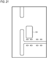
Fig. 21] Fig. 21 shows a state of surroundings of the parked vehicle at the time t - 1. - [
Fig. 22] Fig. 22 shows an image formed by the image forming unit in the state shown inFig. 21 . - [
Fig. 23] Fig. 23 shows a state of surroundings of the parked vehicle at the time t. - [
Fig. 24] Fig. 24 shows an image formed by the image forming unit in the state shown inFig. 23 . - Examples of embodiments will be described in detail below with reference to the accompanying drawings. In each drawing using the description hereinafter, a scale is appropriately changed in order to show each of members in a recognizable size.
-
Fig. 1 is a top view showing avehicle 1 to which a LiDARsensor unit 10 according to a first embodiment of the present invention is attached. As shown inFig. 1 , the LiDARsensor unit 10 is attached to a right front portion, a left front portion, a right rear portion, and a left rear portion of thevehicle 1. -
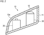
Fig. 2 is a schematic view showing theLiDAR sensor unit 10 attached to the left front portion of thevehicle 1. In the present embodiment, theLiDAR sensor unit 10 is provided together with alamp unit 30 configured to illuminate surroundings of thevehicle 1. Thelamp unit 30 can be a head lamp, a rear combination lamp, a daytime running lamp, a fog lamp, a clearance lamp, or a stop lamp. TheLiDAR sensor unit 10 includes ahousing 11 and anouter cover 12. Thelamp unit 30 and aLiDAR sensor 20 are provided inside a space formed by thehousing 11 and theouter cover 12. -
Fig. 3 is a schematic view showing theLiDAR sensor 20. As shown inFig. 3 , theLiDAR sensor 20 includes alight emitting unit 41, alight receiving unit 42, aMEMS mirror 43, and a converginglens 44. - Light emitted from the
light emitting unit 41 is reflected by theMEMS mirror 43, and is emitted to an outside of thevehicle 1 via the converginglens 44. The light (hereinafter referred to as return light) that is emitted from thelight emitting unit 41 and is reflected by an object is reflected by theMEMS mirror 43 via the converginglens 44, and is incident on thelight receiving unit 42. Thelight emitting unit 41 may emit visible light or emit invisible light such as infrared light or ultraviolet light. TheLiDAR sensor 20 is configured to emit light to the object, and to acquire a distance to the object based on time until the return light is detected. TheMEMS mirror 43 is configured to freely change a direction in which the light reflected by theMEMS mirror 43 is emitted. TheLiDAR sensor 20 is configured to acquire information in a wide range by changing the emission direction of the reflected light by theMEMS mirror 43. -
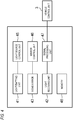
Fig. 4 is a block diagram showing theLiDAR sensor 20. As shown inFig. 4 , theLiDAR sensor 20 includes thelight emitting unit 41, a lightsource control unit 45, theMEMS mirror 43, amirror control unit 46, thelight receiving unit 42, asignal processing unit 47, and amemory 48. The lightsource control unit 45 is configured to control an operation of thelight emitting unit 41. Themirror control unit 46 is configured to control an operation of theMEMS mirror 43. Thememory 48 is a rewritable recording unit. Thesignal processing unit 47 is configured to process a signal output from thelight receiving unit 42 and to output the processed signal to avehicle control unit 3. Thevehicle control unit 3 is configured to control an operation of thevehicle 1. - The
vehicle control unit 3 is configured to control operations of an engine, a brake device, and a steering device according to a signal output in response to an output from theLiDAR sensor 20 or another sensor, an operation of a steering wheel of a driver, an operation of an accelerator pedal of the driver, or an operation of a brake pedal of the driver. Thevehicle control unit 3 is configured to perform automatic driving of thevehicle 1. Alternatively, thevehicle control unit 3 is configured to support driving of the driver. - The
signal processing unit 47 includes a processor and a memory. Examples of the processor include a CPU, an MPU, and a GPU. The processor may include a plurality of processor cores. Examples of the memory include a ROM and a RAM. In the ROM, a program for executing the above-described processing may be stored. The program may include an artificial intelligence program. Examples of the artificial intelligence program include a learned neural network based on deep learning. The processor is configured to specify at least a part of programs stored in the ROM, to load the programs on the RAM, and to execute the processing in cooperation with the RAM. Thesignal processing unit 47 may be implemented by a dedicated integrated circuit such as a microcontroller, an FPGA, or an ASIC. - A detection principle of the
LiDAR sensor 20 will be briefly described with reference toFig. 5 . - The
signal processing unit 47 acquires information indicating how much time is taken for light emitted in which direction to hit the object and be reflected. Based on this, thesignal processing unit 47 outputs direction information and a distance to the object in the direction. Generally, theLiDAR sensor 20 is configured to output data of an azimuth angle θ [°], an elevation angle ϕ [°], and a distance d [m]. - For example, the light
source control unit 45 is configured to control thelight emitting unit 41 such that thelight emitting unit 41 emits light at predetermined time intervals. Themirror control unit 46 is configured to set 100 detection points in a vertical direction and 360 detection points in a horizontal direction in a certain detection range. Themirror control unit 46 is configured to control theMEMS mirror 43 such that theMEMS mirror 43 sequentially reflects the light incident on theMEMS mirror 43 from thelight emitting unit 41 toward each detection point. - The
light receiving unit 42 is configured to detect the return light that hits the object and is reflected by the object at each measurement point, and to output to the signal processing unit 47 a fact that the return light is detected. Since theMEMS mirror 43 sequentially reflects the light emitted from thelight emitting unit 41 toward each measurement point, the return light sequentially detected by thelight receiving unit 42 can be treated as light reflected from each measurement point. For example, when 36000 detection points are set, return light detected at a first time and return light detected at a 36001th time can be treated as light returning from the same direction. Alternatively, in a case in which 0.01 seconds are taken to emit light toward all detection points of 360000 detection points, light emitted after 0.01 seconds from a certain time and light emitted after 0.02 seconds from the certain time can be treated as light emitted in the same direction. - The
signal processing unit 47 measures, for each measurement point, time from a time when thelight emitting unit 41 emits light to a time when the return light is detected. Thesignal processing unit 47 calculates the distance to the object based on the measured time. In this way, thesignal processing unit 47 outputs the distance in association with the direction of each detection point. Thesignal processing unit 47 outputs data such as (θ, ϕ, d) in order to indicate that a distance in a certain direction (θ, ϕ) is d. - As shown in
Fig. 2 , theouter cover 12 is provided in a direction in which the light is emitted from thelight emitting unit 41 of theLiDAR sensor 20 and in a direction in which the light is incident on thelight receiving unit 42. Theouter cover 12 is often formed of a curved surface due to design restrictions of thevehicle 1. In particular, as shown inFig. 1 , when theLiDAR sensor 20 is provided at a corner portion of thevehicle 1, such as the right front portion, the left front portion, the right rear portion, and the left rear portion of thevehicle 1, aportion 12a where a curvature of the curved surface of theouter cover 12 locally increases is present as shown inFig. 2 . - When the light of the
LiDAR sensor 20 passes through theportion 12a where the curvature locally increases in this way, the light is refracted. Therefore, theLiDAR sensor 20 measures a distance in a direction deviated from the originally assumed direction. Therefore, in theLiDAR sensor 20 according to the present embodiment, a direction of large refraction is specified and recorded in thememory 48 before a product is shipped, and theLiDAR sensor 20 does not output data of the direction in the product after the shipment. This processing will be described in detail. -
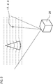
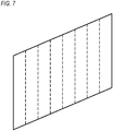
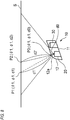
Fig. 6 shows a state in which theLiDAR sensor 20 is operated toward a standard screen S in a state in which theouter cover 12 is not attached to theLiDAR sensor unit 10.Fig. 7 a visualization of an output of theLiDAR sensor 20 that is output in the state shown inFig. 6 .Figs. 7 and9 are schematic views showing the output of theLiDAR sensor 20. A large number of output points are actually present. However,Figs. 7 and9 are shown with the number of points smaller than the number of the actual output points for convenience of drawing. - The standard screen S is a flat screen having a predetermined size. In
Fig. 6 , theLiDAR sensor 20 is operated by separating the standard screen S from theLiDAR sensor 20 by a predetermined distance. Since the standard screen S is flat, a point group of the measurement points in the output of theLiDAR sensor 20 also forms a flat surface. Thesignal processing unit 47 records, in therewritable memory 48, an output when the standard screen S is sensed in a state in which theouter cover 12 is not attached to theLiDAR sensor unit 10. -
Fig. 8 shows a state in which theLiDAR sensor 20 is operated toward the standard screen S in a state in which theouter cover 12 is attached to theLiDAR sensor unit 10.Fig. 9 a visualization of an output of theLiDAR sensor 20 that is output in the state shown inFig. 8 . - When the
LiDAR sensor 20 is operated in a state in which theouter cover 12 is attached, as shown inFig. 8 , the light is refracted at theportion 12a where the curvature is locally large in theouter cover 12. InFig. 8 , a trajectory of the passing light in the case in which theouter cover 12 is not provided is shown by a broken line. InFig. 8 , a state of the refraction of the light is shown in a deformed manner. - As shown in
Fig. 6 , coordinates at which the light emitted in a direction (θ1, (ϕ1) toward theportion 12a having the large curvature reaches the standard screen S are expressed as P1 = (θ1, ϕ1, d1). That is, in the direction (θ1, ϕ1), a distance to the standard screen S is d1. - As shown in
Fig. 8 , coordinates at which the light emitted in the direction (θ1, (ϕ1) toward theportion 12a having the large curvature and refracted by theportion 12a reaches the standard screen S are expressed as P2 = (θ1, ϕ1, d2). - That is, actually, if the
outer cover 12 is attached even though the distance to the standard screen S in the direction (θ1, (ϕ1) is d1, theLiDAR sensor 20 erroneously recognizes the distance to the standard screen S in the direction (θ1, (ϕ1) as d2. Therefore, when data output from theLiDAR sensor 20 as it is visualized, as shown inFig. 9 , the visualized data is different from data inFig. 7 . - Therefore, in the present embodiment, the output when the standard screen S is sensed in the state in which the
outer cover 12 is attached to theLiDAR sensor unit 10 is compared with the output when the standard screen S is sensed in the state in which theouter cover 12 is not attached to theLiDAR sensor unit 10. When a difference of distances in the same direction is equal to or greater than a threshold value, theLiDAR sensor 20 does not output the distances in the direction. - That is, in examples shown in
Figs. 6 to 9 , for the direction (θ1, ϕ1), when an absolute value Δd = |d2 - d1| of a difference between the distance d1 when theouter cover 12 is not attached to theLiDAR sensor unit 10 and the distance d2 when theouter cover 12 is attached to theLiDAR sensor unit 10 is larger than a threshold value da (Δd > da), the direction is recorded in thememory 48 as a non-output direction. - In the shown example, the
LiDAR sensor 20 calculates a length of an optical path along which the refracted light travels as the distance d2. That is, the distance d2 is a sum of a distance d0 from theLiDAR sensor 20 to theportion 12a and a distance d2' from theportion 12a to a point P2. When a distance from theportion 12a to a point P1 is d1', Δd = d2 - d1 = (d0 + d2') - (d0 + d1') = d2' - d1'. When d2' - d1' is larger than the predetermined value da, thesignal processing unit 47 records the direction (θ1, (ϕ1) in thememory 48 as the non-output direction. - Further, when the
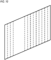
LiDAR sensor 20 is normally used, thesignal processing unit 47 reads out the non-output direction from thememory 48 and does not output data for a direction corresponding to the non-output direction as shown inFig. 10. Fig. 10 visualizes and shows output data output from thesignal processing unit 47 to thevehicle control unit 3 when the inspection screen S is detected. As shown inFig. 10 , even if a part of the data output from theLiDAR sensor 20 is missing, an entire image can be grasped. - In general, a large number of measurement points (measurement directions) of the
LiDAR sensor 20 are present. Therefore, even if measurement points affected by the refraction of theouter cover 12 are ignored, a good resolution is easily maintained. Rather, according to the present embodiment, since it is not necessary to correct data due to refraction of theouter cover 12 or execute exceptional processing, a processing load of thesignal processing unit 47 is reduced. - The
signal processing unit 47 may determine whether a ratio n/m of the number (n) of non-detection directions to the number (m) of all the measurement points is equal to or greater than 0.1. When the ratio is equal to or greater than 0.1, thesignal processing unit 47 may output an error signal to thevehicle control unit 3 and may output data for the direction corresponding to the non-output direction. - In the above-described embodiment, an example has been described in which the measurement points before and after the attachment of the
outer cover 12 are treated. However, the present invention is not limited thereto. In theLiDAR sensor unit 10, an inner lens may be provided inside a space formed by thehousing 11 and theouter cover 12. Even before and after the attachment of the inner lens, a direction to be measured may change due to refraction of the inner lens. The present invention can also be applied to this case. - That is, the output when the standard screen S is sensed in the state in which the inner lens is attached to the
LiDAR sensor unit 10 is compared with the output when the standard screen S is sensed in the state in which the inner lens is not attached to theLiDAR sensor unit 10. When a difference of distances in the same direction is equal to or greater than a threshold value, theLiDAR sensor 20 may not output the distances in the direction. - In the present embodiment, the output when the standard screen S is sensed in the state in which the
outer cover 12 is not attached to theLiDAR sensor unit 10 and the output when the standard screen S is sensed in the state in which theouter cover 12 is attached to theLiDAR sensor unit 10 are recorded in therewritable memory 48. - The
outer cover 12 may be scratched or damaged by a flying stone or the like. As described above, refraction may occur at a portion where a scratch is formed or the light may be scattered, and the distance may not be measured properly. Even if the scratch is small and inconspicuous, if the scratch is located on an extension line of the measurement direction, theLiDAR sensor 20 is affected by the scratch. However, it is not realistic to replace theouter cover 12 since the small scratch is formed. - Therefore, in the present embodiment, it is possible to periodically update information recorded in the
memory 48. For example, in a periodic inspection of the vehicle or the like, an inspection using the above-described standard screen S is performed. In the inspection, the output when the standard screen S is sensed in the state in which theouter cover 12 is not attached to theLiDAR sensor unit 10 and the output when the standard screen S is sensed in the state in which theouter cover 12 is attached to theLiDAR sensor unit 10 can be acquired and rewritten periodically. Accordingly, it is possible not to output the data for the direction in which the distance cannot be measured due to the scratch, and it is possible to avoid a defect caused by the scratch. - Even when the
outer cover 12 is replaced, by updating the information recorded in thememory 48, it is possible not to output data in a direction in which a degree of refraction is large according to a shape of theouter cover 12 after the replacement. - An electronic circuit that is configured to implement a function of specifying the non-output direction and not outputting the distance in the non-output direction to the
vehicle control unit 3 and that is described with reference toFigs. 6 to 10 may be provided separately from an electronic circuit configured to implement a function of detecting the incidence of the light on the light receiving unit and calculating the distance of the object. That is, the electronic circuit incorporated in theLiDAR sensor 20 is configured to implement the function of detecting the incidence of the light on the light receiving unit and calculating the distance of the object, and the electronic circuit configured to implement the function of specifying the non-output direction and not outputting the distance in the non-output direction to thevehicle control unit 3 may be provided in a middle of a communication path between theLiDAR sensor 20 and thevehicle control unit 3. - A LiDAR sensor can measure a precise distance. The LiDAR sensor can acquire a large amount of measurement data at an extremely short time interval. However, as described above, since the distance can be measured with an extremely high resolution and the measurement data can be acquired at the extremely short time interval, the LiDAR sensor is greatly affected by a fluctuation due to a vibration of the vehicle, sound, heat, wind, mere noise, or the like.
- In order to be used for the automatic driving of the vehicle, an output of the LiDAR sensor including fine distance information such as 0.1 mm or less is unnecessary.
- Therefore, in a second embodiment of the present invention to be described next, the
LiDAR sensor unit 10 suitable for a vehicle that can be automatically driven is provided. - The
LiDAR sensor unit 10 according to the second embodiment has the same structure and detection principle as theLiDAR sensor unit 10 described with reference toFigs. 1 to 5 in the above-described first embodiment. Therefore, the description of the structure and the detection principle of theLiDAR sensor unit 10 according to the second embodiment will be omitted. -
Fig. 11 is a flowchart showing processing executed by thesignal processing unit 47. - As shown in
Fig. 11 , thesignal processing unit 47 calculates that a distance to an object in the direction (θ, ϕ) at the time t is D (step S01). That is, raw data at the time t is (θ, ϕ, D). Thesignal processing unit 47 records the raw data (θ, ϕ, D) at the time t in thememory 48. - Next, the
signal processing unit 47 reads out last 10 distances for the certain direction (θ, ϕ) (step S02). Thesignal processing unit 47 extracts a minimum value dmin and a maximum value dmax from these values. Thesignal processing unit 47 calculates an average value dmean of the last 10 distances for the certain direction (θ, ϕ) (step S03). Thesignal processing unit 47 records dmin, dmax, and dmean in thememory 48. - Next, the
signal processing unit 47 calculates, for the certain direction (θ, ϕ), a difference Δd between an immediately preceding distance D [t - 1] and a distance D [t] measured this time (step S04). Thesignal processing unit 47 calculates Δd = D [t] - D [t - 1]. Thesignal processing unit 47 records the difference Δd in thememory 48. - The
signal processing unit 47 reads out the minimum value dmin and the maximum value dmax from thememory 48 and multiplies a difference between the minimum value dmin and the maximum value dmax by a coefficient of 0.5 to calculate a fluctuation threshold value dth (step S05). Thesignal processing unit 47 records the fluctuation threshold value dth in thememory 48. - The
signal processing unit 47 reads out the difference Δd and the fluctuation threshold value dth from thememory 48, and compares absolute values of the difference Δd and the fluctuation threshold value dth (step S06). - When the absolute value of the difference Δd is larger than the absolute value of the fluctuation threshold value dth (step S06: No), the
signal processing unit 47 outputs the raw data D [t] as the distance in the certain direction (θ, ϕ). That is, thesignal processing unit 47 outputs (θ, ϕ, D [t]) to thevehicle control unit 3 as measurement data at the time t (step S07). - When the absolute value of the difference Δd is smaller than the absolute value of the fluctuation threshold value dth (step S06: Yes), the
signal processing unit 47 outputs the average value dmean as the distance in the certain direction (θ, ϕ). That is, thesignal processing unit 47 outputs (θ, ϕ, dmean) to thevehicle control unit 3 as measurement data at the time t (step S08). -
Fig. 12 is a graph plotting the measurement data and the raw data that are obtained in this way. InFig. 12 , for the certain direction (θ, ϕ), the distance D of the raw data output from theLiDAR sensor 20 is indicated by X, and the distance d of data (referred to as output data) that is processed by thesignal processing unit 47 and is output to thevehicle control unit 3 is indicated by a square. A portion where the distance of the raw data and the distance of the output data overlap each other is represented by the distance (the square) of the output data. - As shown in
Fig. 12 , the fluctuation of the output data represented by the square is reduced as compared with the raw data represented by x. - Incidentally, the present inventor has noticed that the output of the LiDAR sensor is likely to fluctuate finely. However, even if the measurement data that fluctuates finely is output to the
vehicle control unit 3 as it is, thevehicle control unit 3 does not control thevehicle 1 using a value that fluctuates finely in this way. - In order to reduce this fine fluctuation, it is conceivable that a certain threshold value is set and a fluctuation within the threshold value is not output to the
vehicle control unit 3. However, the present inventor has noticed that, in the output of the LiDAR sensor, the threshold value suitable for a plurality of factors such as a temperature, humidity, or a traveling state changes. That is, even if a certain threshold value is an appropriate threshold value in a certain situation, too many fluctuations beyond the threshold value occur and the threshold value becomes meaningless in another situation. Alternatively, too many fluctuations below the threshold value occur and only certain distance data is output in another situation. - Therefore, the present inventor has completed the present invention in which the distance data in a predetermined period is always accumulated, the threshold value is determined based on a maximum value and a minimum value during the predetermined period, and the measurement data is output to the
vehicle control unit 3 with the distance within the threshold value that fluctuates depending on the time as a constant distance. According to this aspect, since the fluctuation threshold value dth suitable for the situation is appropriately set, it is possible to smooth the fluctuation of the distance data that fluctuates due to various factors with the appropriate fluctuation threshold value dth. - In the above-described embodiment, the reading of the nearest 10 distances in the certain direction has been described. However, the number of distances to be read out is not limited to 10. Any number of pieces of data may be read out. As the number of pieces of data to be read is set to be large, the data output to the
vehicle control unit 3 is less likely to fluctuate. This coefficient may be fluctuated according to a driving situation or the like according to a signal or the like output from thevehicle control unit 3. For example, when it is assumed that there is little change in a state of the outside of the vehicle, such as during traveling on a highway, a large number of pieces of data may be read out. - In the above-described embodiment, it has been described that the coefficient of 0.5 is multiplied by (dmax - dmin) in order to calculate the fluctuation threshold value. However, the coefficient to be multiplied by (dmax - dmin) can be set freely. The coefficient can be set to a value of 0 to 1. When the coefficient is increased, it is possible to reduce the fluctuation in the distance output from the LiDAR sensor unit to the
vehicle control unit 3. When the coefficient is reduced, the distance output from the LiDAR sensor unit to thevehicle control unit 3 is easily reproduced faithfully to the raw data output from the LiDAR sensor. - This coefficient may be fluctuated according to the driving situation or the like according to the signal or the like output from the
vehicle control unit 3. For example, when it is assumed that there is little change in the state of the outside of the vehicle, such as during traveling on a highway, a large coefficient may be set. - In the above-described embodiment, an example has been described in which the average value dmean at last 10 points is set as the distance of the output data when the fluctuation value is within the fluctuation threshold value (step S06: Yes). However, the present invention is not limited thereto. Instead of the average value dmean, a distance of any of the last 10 points may be output, or the minimum value dmin or the maximum value dmax may be output.
- A LiDAR sensor can measure a distance at a large number of measurement points, and can accurately grasp a surrounding situation. However, since the LiDAR sensor outputs a large number of measurement points in short time, a large burden is generated on a processing apparatus configured to process the measurement points. In a control of a vehicle in automatic driving or manual driving, some action is required when a situation changes.
- Therefore, in a third embodiment of the present invention, a LiDAR sensor unit having an output suitable for the control of the vehicle is provided.
- Next, a LiDAR sensor unit 110 according to the third embodiment of the present invention will be described.
- The LiDAR sensor unit 110 according to the third embodiment also has the same structure as the
LiDAR sensor unit 10 described with reference toFigs. 1 to 3 in the above-described first embodiment. A detection principle of the LiDAR sensor unit 110 according to the third embodiment is also the same as the detection principle described with reference toFig. 5 . Therefore, the description of the structure and the detection principle of the LiDAR sensor unit 110 according to the third embodiment will be omitted. - A functional block of the LiDAR sensor unit 110 according to the third embodiment is different from a functional block of the
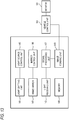
LiDAR sensor unit 10 according to the first embodiment.Fig. 13 is a block diagram showing a LiDAR sensor 120 according to the third embodiment of the present invention. As shown inFig. 13 , the LiDAR sensor 120 includes alight emitting unit 141, a lightsource control unit 145, aMEMS mirror 143, amirror control unit 146, alight receiving unit 142, a signal processing unit 147, amemory 148, and animage forming unit 149. The lightsource control unit 145 is configured to control an operation of thelight emitting unit 141. Themirror control unit 146 is configured to control an operation of theMEMS mirror 143. Thememory 148 is a rewritable recording unit. The signal processing unit 147 is configured to process a signal output from thelight receiving unit 142 and to output the processed signal to theimage forming unit 149. Thevehicle control unit 103 is configured to control an operation of avehicle 101. Theimage forming unit 149 is configured to form an image based on the signal output from the signal processing unit 147 and to output the image to thevehicle control unit 103. -
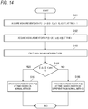
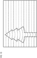
Fig. 14 is a flowchart showing processing executed by theimage forming unit 149.Fig. 15 shows a state of a front of a vehicle at the time t - 1 before predetermined time from the certain time t. A point group inFig. 15 shows a visualization of measurement data of the LiDAR sensor 120 as it is. As shown inFig. 15 , at the time t - 1, a tree T is present on a left side of a front of thevehicle 101. At the time t - 1, the LiDAR sensor 120 measures the distance d for all measurement points. Theimage forming unit 149 acquires measurement data P [t - 1] = (θ [t - 1], ϕ [t - 1], d [t - 1]) at the time t - 1 (step S101). -
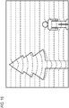
Fig. 16 shows a state of the front of the vehicle at the certain time t. A point group inFig. 16 shows a visualization of measurement data of the LiDAR sensor 120 as it is. At the time t, the tree T is present on the left side of the front of thevehicle 101, and a pedestrian is present on a right side of the front of thevehicle 101. That is, when time changes from the time t - 1 to the time t, the pedestrian enters the front of the vehicle. - At the time t, the LiDAR sensor 120 also measures the distance for all the measurement points. The
image forming unit 149 acquires measurement data P [t] = (θ [t], ϕ [t], d [t]) at the time t (step S102). - The
image forming unit 149 calculates the fluctuation Δd = d [t] - d [t - 1] of the distance in the same direction (θ, ϕ) at the time t - 1 and the time t (step S103). - The
image forming unit 149 forms an image in which the output of the LiDAR sensor 120 at the time t is visualized. At this time, as shown inFig. 17 , theimage forming unit 149 emphasizes a portion changed from the time t - 1 to the time t to form an image. - First, the
image forming unit 149 determines whether Δd is greater than the predetermined threshold value dth for all the directions (step S104). - For a direction in which Δd is smaller than the predetermined threshold value dth (step S104: Yes), the
image forming unit 149 visualizes the distance d [t] at the time t based on a normal method (step S 105). For example, the distance d [t] is drawn with a black dot on a white background for the directions θ and ϕ. - When Δd is equal to or greater than the predetermined threshold value dth (step S104: No), the
image forming unit 149 visualizes the distance d [t] at the time t based on a method different from the normal method (step S 106). For example, the distance d [t] is drawn with a red circle on the white background for the directions θ and ϕ. - In this way, the
image forming unit 149 forms the image shown inFig. 17 and outputs the image to thevehicle control unit 103. Theimage forming unit 149 forms an image in any format such as BMP, PNG, GIF, JPEG, or TIFF. - That is, the
image forming unit 149 compares the first measurement data P [t - 1] acquired from the LiDAR sensor 120 at the first time t - 1 with the second measurement data P [t] acquired from the LiDAR sensor 120 at the second time t after predetermined time has elapsed from the first time t - 1, and generates an image in which the second measurement data P [t] having the same direction and a difference in distance being equal to or greater than the threshold value is represented in a mode different from that of the second measurement data P [t] having the same direction and a difference in distance being less than the threshold value. - The
vehicle control unit 103 may acquire an image from theimage forming unit 149 and may display the image on a display provided in a vehicle interior. - In this way, according to the LiDAR sensor unit 110 in the present embodiment, a measurement point that is different from an immediately preceding situation is displayed separately from a point that is not changed from the immediately preceding situation. Since the measurement point different from the immediately preceding situation can be instantly grasped, the
vehicle control unit 103 can instantly grasp the point different from the immediately preceding situation and can quickly perform a necessary operation. For example, in the present embodiment, thevehicle control unit 103 can instantly grasp the appearance of the pedestrian different from the immediately preceding situation, and can stop thevehicle 101. - The
image forming unit 149 may be integrated with the signal processing unit 147 or may be separated from the signal processing unit 147. Theimage forming unit 149 may be provided in a middle of a communication path between the signal processing unit 147 and thevehicle control unit 103. - Since a LiDAR sensor can acquire information on surroundings of a vehicle, it is conceivable to use the LiDAR sensor as a security sensor configured to monitor a suspicious person trying to open a door while the vehicle is parked. However, a viewpoint is present that a LiDAR consumes a large amount of power and is difficult to be used as a security sensor.
- Therefore, a fourth embodiment of the present invention provides a power saving vehicle security system using the LiDAR sensor.
-
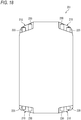
Fig. 18 is a top view showing thevehicle 1 to which avehicle security system 202 according to the present embodiment is attached. Thevehicle security system 202 includes a plurality ofLiDAR sensor units 210. As shown inFig. 18 , theLiDAR sensor unit 210 is attached to a right front portion, a left front portion, a right rear portion, and a left rear portion of thevehicle 1. - Since the
LiDAR sensor unit 210 used in the present embodiment is the same as theLiDAR sensor unit 10 described with reference toFigs. 2 and3 in the above-described first embodiment, the description thereof will be omitted. -
Fig. 19 is a block diagram showing thevehicle security system 202. As shown inFig. 19 , thevehicle security system 202 includes aLiDAR sensor unit 210, alamp unit 230, animage forming unit 251, animage comparing unit 252, and a lamp control unit 253 (a control unit). As shown inFig. 19 , theLiDAR sensor unit 210 includes alight emitting unit 241, a lightsource control unit 245, aMEMS mirror 243, amirror control unit 246, alight receiving unit 242, and asignal processing unit 247. The lightsource control unit 245 is configured to control an operation of thelight emitting unit 241. Themirror control unit 246 is configured to control an operation of theMEMS mirror 243. Thelamp control unit 253 is configured to control turning on and off of thelamp unit 230. Thesignal processing unit 247 is configured to process a signal output from thelight receiving unit 242 and to output the processed signal to thevehicle control unit 203. Thevehicle control unit 203 is configured to control an operation of avehicle 201. -
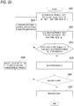
Fig. 20 is a flowchart showing processing executed by thevehicle security system 202.Fig. 21 shows a state of surroundings of the parkedvehicle 201 at the time t - 1 before predetermined time from the certain time t. At the time t - 1, thevehicle 201 is parked in a parking lot.Fig. 22 is an image I [t - 1] formed by theimage forming unit 251 based on measurement data acquired by theLiDAR sensor 220 in the state shown inFig. 21 . - At the time t - 1, the
LiDAR sensor 220 measures a distance for all measurement points. Theimage forming unit 251 acquires the measurement data P [t - 1] = (θ [t - 1], ϕ [t - 1], d [t - 1]) at the time t - 1, and forms the image I [t - 1] shown inFig. 22 (step S201). -
Fig. 23 shows a state of surroundings of the parkedvehicle 201 at the time t. At the time t, a pedestrian A approaches the parkedvehicle 201 from upper right inFig. 23 .Fig. 24 is an image I [t] formed by theimage forming unit 251 based on measurement data acquired by theLiDAR sensor 220 in the state shown inFig. 23 . - At the time t, the
LiDAR sensor 220 measures a distance for all the measurement points. Theimage forming unit 251 acquires the measurement data P [t] = (θ [t], ϕ [t], d [t]) at the time t, and forms the image I [t] shown inFig. 24 (step S202). - The
image comparing unit 252 compares the image I [t - 1] acquired at the time t - 1 with the image I [t] acquired at the time t. Theimage comparing unit 252 determines whether a difference equal to or greater than a predetermined value is generated between the two images I [t - 1] and I [t] (step S203). For example, when the number of pixels having a difference between the two images I [t - 1] and I [t] is equal to or greater than a predetermined value, theimage comparing unit 252 determines that the difference equal to or greater than the predetermined value is generated. For example, when the number of pixels having a difference is 3% or more with respect to the total number of pixels constituting the image, theimage comparing unit 252 determines that the difference equal to or greater than the predetermined value is generated between the two images I [t - 1] and I [t]. A ratio of the number of pixels having a difference to all the pixels to be set to a threshold value may be changed stepwisely by a user, such as 5% or 10%. - When no difference equal to or greater than the predetermined value is present between the two images I [t - 1] and I [t] (step S203: No), the
vehicle security system 202 executes step S201 again after a first period elapses (step S204). - When the difference equal to or greater than the predetermined value is generated between the two images I [t - 1] and I [t] (step S203: Yes), the
image comparing unit 252 performs alarm processing (step S205). - In the present embodiment, the
image comparing unit 252 performs the following alarm processing. First, theimage comparing unit 252 identifies in which direction the difference is generated when viewed from thehost vehicle 201. Further, theimage comparing unit 252 outputs the identified direction to the lightsource control unit 245 and themirror control unit 246 of theLiDAR sensor 220. In the shown example, the direction to be identified is only an upper right position direction of thehost vehicle 201. However, when the difference is generated in a plurality of directions, the plurality of directions may be specified and output to theLiDAR sensor 220. Further, the lamp control unit turns on thelamp unit 230 so as to illuminate the identified direction. Theimage comparison unit 252 may output a signal notifying an abnormality to a mobile phone owned by the user. - Further, the
image comparing unit 252 determines whether an alarm release signal has been acquired (step S206). For example, theimage comparing unit 252 is able to acquire a predetermined alarm release signal from thevehicle control unit 203 or the mobile phone of the user. - When the
image comparing unit 252 acquires the alarm release signal within a predetermined period (step S206: Yes), theimage comparing unit 252 releases the alarm (step S207) and ends the processing. - When the
image comparison unit 252 does not acquire the alarm release signal within the predetermined period (step S206: No), thevehicle security system 202 executes step S201 after a second predetermined period elapses (step S208). Here, the second predetermined period is set to be shorter than the first predetermined period. For example, the first predetermined period is 30 seconds, and the second predetermined period is 0.5 seconds. Alternatively, the first predetermined period is 60 seconds, and the second predetermined period is one second. That is, thevehicle security system 202 repeats steps S201 to S203 at a cycle of approximately 30 seconds. - Measurement data acquired at a first predetermined time interval is referred to as first measurement data. Measurement data acquired at a second predetermined time interval is referred to as second measurement data. In other words, in the above-described embodiment, the second measurement data is acquired in the second period shorter than the first period when a fluctuation greater than the predetermined value occurs during the measurement of the first measurement data.
- Since the
LiDAR sensor 220 can acquire a shape of the object with high accuracy, theLiDAR sensor 220 is suitable for a security system. In many cases, theLiDAR sensor 220 is mounted on thevehicle 201 that can be automatically driven. TheLiDAR sensor 220 mounted on thevehicle 201 that can be automatically driven operates while thevehicle 201 travels, but is not used while thevehicle 201 is parked. Thevehicle security system 202 using theLiDAR sensor 220 can use theLiDAR sensor 220 that is not used while thevehicle 201 is parked, and it is not necessary to use a separate sensor only for the vehicle security system, which is rational. - Further, a vehicle security sensor 2 according to the present embodiment is configured to acquire the second measurement data in the second cycle shorter than the first cycle when the fluctuation greater than the predetermined value occurs during the measurement of the first measurement data. That is, in a normal state, the
LiDAR sensor 220 is operated in the first cycle so as to reduce power consumption, and in a case in which any state changes and an abnormality is suspected, theLiDAR sensor 220 can be operated in the second cycle to perform investigating in detail. Accordingly, it is possible to acquire highly accurate information when necessary while power consumption is reduced. - In the present embodiment, the light
source control unit 245 of thevehicle security system 202 may operate theLiDAR sensor 220 while thevehicle 201 is parked at a resolution lower than a resolution of sensing performed at a time of traveling, or may operate theLiDAR sensor 220 while thevehicle 201 is parked at a cycle longer than a cycle of the sensing performed at the time of traveling. - When the
LiDAR sensor 220 is used for security purposes while thevehicle 201 is parked, a resolution lower than the resolution (the number of measurement points) required at the time of traveling is sufficient. When theLiDAR sensor 220 is used for the security purposes while thevehicle 201 is parked, a cycle longer than a cycle (a scan cycle) obtained at the time of traveling is sufficient. By operating theLiDAR sensor 220 with a low resolution or a long cycle, the power consumed by theLiDAR sensor 220 can be reduced. - When the
image comparison unit 252 specifies the direction in which the difference is generated in the present embodiment, theimage comparing unit 252 divides the image I [t] acquired at the time t into 12 regions in a circumferential direction around thehost vehicle 201, and specifies the divided regions. Instead of specifying the direction, theimage comparing unit 252 may specify which region the pixel having the difference belongs to, and may output the region to which the pixel belongs to thelamp control unit 253. In this case, thelamp control unit 253 may turn on thelamp unit 230 capable of emitting light toward the input region. - In the above-described embodiment, the alarm processing is performed immediately when the difference equal to or greater than the predetermined value is generated between the image I [t - 1] and the image I [t]. However, when the difference equal to or greater than the predetermined value is generated, it may be determined whether the difference matches, for example, a pattern registered as an action pattern of a suspicious person, and the alarm processing may be performed when the difference matches the pattern.
- The alarm processing may be a known method of notifying an owner of the
vehicle 201 such as emitting light and emitting a sound. - In the present embodiment, the
vehicle security system 202 may be capable of identifying the owner of thevehicle 201 or a registered person (referred to as a user) as an unregistered person. Thevehicle security system 202 may include a userinformation recording unit 254. The userinformation recording unit 254 records a specific shape associated with the user. After determining that a difference is present between the image I [t - 1] at the time t - 1 and the image I [t] at the time t, theimage comparing unit 252 determines whether the difference in the image I [t] at the time t matches the shape recorded in the userinformation recording unit 254. If the difference matches the shape, thelamp control unit 253 turns on thelamp unit 230 based on a method different from that in a case in which the difference does not match the shape. - For example, if the difference matches the shape recorded in the user
information recording portion 254, thelamp unit 230 may be constantly on toward the corresponding direction, and if the difference does not match the shape recorded in the userinformation recording portion 254, thelamp unit 230 may be blinked toward the corresponding region. For example, the userinformation recording unit 254 can record a shape of a face of the user, a shape of a key holder owned by the user, and the like. - The
lamp control unit 253 differentiating a lighting mode of thelamp unit 230 depending on whether the shapes match or do not match includes differentiating lighting and blinking of thelamp unit 230, differentiating blinking of thelamp unit 230, differentiating lighting colors of thelamp unit 230, and differentiating brightness of thelamp unit 230. When thelamp unit 230 includes a plurality of light sources, changing the lighting mode of thelamp unit 230 includes changing the number and a shape of the light sources to be turned on. - The
image forming unit 251, theimage comparing unit 252, and thelamp control unit 253 may be integrated with thesignal processing unit 247 or may be separated from thesignal processing unit 247. Theimage forming unit 251, theimage comparing unit 252, and thelamp control unit 253 may be provided in a middle of a communication path between thesignal processing unit 247 and thevehicle control unit 203. - In the above-described embodiment, when the difference is present between the image at the time t - 1 and the image at the time t, the
image comparing unit 252 outputs the direction in which the difference is present to thelamp control unit 253, and thelamp control unit 253 emits light toward the corresponding direction. However, the present invention is not limited thereto. In a case in which theLiDAR sensor unit 210 is provided with a directional speaker, when the difference is present between the image at the time t - 1 and the image at the time t, theimage comparing unit 252 may output the direction in which the difference is present to a sound source control unit, and the sound source control unit may cause the directional speaker to emit a sound toward the corresponding direction. - Further, in the above-described embodiment, the
LiDAR sensor 220 provided in the right front portion, the left front portion, the right rear portion, and the left rear portion of thevehicle 201 has been described. However, the present invention can be applied to all theLiDAR sensors 220 regardless of a mounting position of thevehicle 201. - Further, in the above-described embodiment, an example has been described in which the
LiDAR sensor 220 is provided together with thelamp unit 230 inside theouter cover 12 and thehousing 11. Theouter cover 12 and thehousing 11 are common. However, the present invention is not limited thereto. TheLiDAR sensor 220 may be provided independently of thelamp unit 230. TheLiDAR sensor 220 may be provided inside theouter cover 12 and thehousing 11 that are common to other sensors such as a camera and a millimeter wave radar. - The above-described embodiments are merely examples for facilitating an understanding of the present invention. The configurations according to the above-described embodiments can be appropriately modified and improved without departing from the spirit of the present invention.
- In the above-described embodiment, the LiDAR sensor unit provided in the right front portion, the left front portion, the right rear portion, and the left rear portion of the
vehicle 1 has been described. However, the present invention can be applied to all the LiDAR sensor units regardless of a mounting position of the vehicle. - Further, in the above-described embodiment, an example has been described in which the LiDAR sensor is provided together with the lamp unit inside the outer cover and the housing. The outer cover and the housing are common. However, the present invention is not limited thereto. The LiDAR sensor may be provided independently of the lamp unit. Alternatively, the LiDAR sensor may be provided inside the outer cover and the housing that are common to other sensors such as a camera and a millimeter wave radar.
- The present application is based on a
Japanese patent application (Patent Application No. 2019-002788) filed on January 10, 2019 Japanese patent application (Patent Application No. 2019-002789) filed on January 10, 2019 Japanese patent application (Patent Application No. 2019-002790) filed on January 10, 2019 Japanese patent application (Patent Application No. 2019-002791) filed on January 10, 2019 - The present invention provides a LiDAR sensor unit in which, even if a lens element is provided, the lens element is less likely to affect measurement data.
-
- 1
- vehicle
- 3
- vehicle control unit
- 10
- LiDAR sensor unit
- 11
- housing
- 12
- outer cover (lens element)
- 20
- LiDAR sensor
- 30
- lamp unit
- 41
- light emitting unit
- 42
- light receiving unit
- 43
- MEMS mirror
- 44
- converging lens
- 45
- light source control unit
- 46
- mirror control unit
- 47
- signal processing unit (processing unit)
- 48
- memory (recording unit)
- 101
- vehicle
- 103
- vehicle control unit
- 110
- LiDAR sensor unit
- 111
- housing
- 112
- outer cover
- 120
- LiDAR sensor
- 141
- light emitting unit
- 142
- light receiving unit
- 143
- MEMS mirror
- 144
- converging lens
- 145
- light source control unit
- 146
- mirror control unit
- 147
- signal processing unit (processing unit)
- 148
- memory
- 149
- image forming unit
- 201
- vehicle
- 202
- vehicle security system
- 203
- vehicle control unit
- 210
- LiDAR sensor unit
- 220
- LiDAR sensor
- 230
- lamp unit (light source)
- 241
- light emitting unit
- 242
- light receiving unit
- 243
- MEMS mirror
- 244
- converging lens
- 245
- light source control unit
- 246
- mirror control unit
- 247
- signal processing unit
- 251
- image forming unit
- 252
- image comparing unit
- 253
- lamp control unit (control unit)
- 254
- user information recording unit
- S
- standard screen
- θ
- direction angle
- ϕ
- elevation angle
- d
- distance
- dmax
- maximum value
- dmin
- minimum value
- dmean
- average value
- dth
- fluctuation threshold value
- Δd
- difference
- dth
- threshold value
- Δd
- fluctuation
- A
- pedestrian
Claims (9)
- A LiDAR sensor unit comprising:a LiDAR sensor;a lens element that is provided on an optical path of light emitted from the LiDAR sensor; anda processing unit configured to output measurement data including a direction and a distance that are to be measured, the measurement data being measured by the LiDAR sensor,wherein the processing unit is configured not to output the measurement data for a specific direction in which the direction is the same and distances are different before and after attachment of the lens element in the same environment.
- The LiDAR sensor unit according to claim 1,
wherein the specific direction in which the direction is the same and distances are different before and after attachment of the lens element in the same environment is recorded in a rewritable recording unit. - A LiDAR sensor unit comprising:a LiDAR sensor;a lens element that is provided on an optical path of light emitted from the LiDAR sensor; anda processing unit configured to output measurement data including a direction and a distance that are to be measured, the measurement data being measured by the LiDAR sensor,wherein the processing unit does not cause the LiDAR sensor to emit detection light in a specific direction in which the direction is the same and distances are different before and after attachment of the lens element in the same environment.
- A LiDAR sensor unit comprising:a LiDAR sensor;a lens element that is provided on an optical path of light emitted from the LiDAR sensor;a processing unit configured to output measurement data including a direction and a distance that are to be measured, the measurement data being measured by the LiDAR sensor; anda recording unit configured to record a specific direction in which the direction is the same and distances are different before and after attachment of the lens element in the same environment.
- A LiDAR sensor unit comprising:a LiDAR sensor that is mounted on a vehicle and is capable of outputting at least distance data to be measured; anda processing unit configured to output, as measurement data, data including distance data acquired by the LiDAR sensor,wherein the processing unit outputs the measurement data with a distance within a predetermined fluctuation threshold value as a constant distance, the predetermined fluctuation threshold value being determined based on a maximum value and a minimum value of the distance data accumulated in a predetermined period.
- The LiDAR sensor unit according to claim 5,
wherein the processing unit outputs, in an (n-1)-th predetermined period, the measurement data with the distance within the fluctuation threshold value as a constant distance, the fluctuation threshold value being determined based on a maximum value and a minimum value of the distance data accumulated in an n-th predetermined period. - A LiDAR sensor unit comprising:a LiDAR sensor that is mounted on a vehicle and is configured to output measurement data including a direction and a distance of an object;a processing unit configured to process the measurement data output from the LiDAR sensor; andan image forming unit configured to compare first measurement data acquired from the LiDAR sensor at a first time with second measurement data acquired from the LiDAR sensor at a second time after predetermined time has elapsed from the first time, and to generate an image in which the second measurement data having the same direction and a difference in distance being equal to or greater than a threshold value is represented in a mode different from that of the second measurement data having the same direction and a difference in distance being less than the threshold value.
- A vehicle security system comprising:a LiDAR sensor that is mounted on a vehicle and is configured to acquire information of a surrounding of the vehicle; anda control unit configured to control the LiDAR sensor,wherein the control unit is configured to acquire first measurement data in a first cycle while the vehicle is parked, and to acquire second measurement data in a second cycle shorter than the first cycle when a fluctuation greater than a predetermined value occurs in the first measurement data.
- The vehicle security system according to claim 8,
wherein the control unit is configured to acquire the second measurement data in the second cycle in a direction range narrower than a direction range measured in the first cycle, the direction range measured in the first cycle including a direction in which a fluctuation greater than a predetermined value occurs in the first measurement data.
Applications Claiming Priority (5)
| Application Number | Priority Date | Filing Date | Title |
|---|---|---|---|
| JP2019002791 | 2019-01-10 | ||
| JP2019002790 | 2019-01-10 | ||
| JP2019002789 | 2019-01-10 | ||
| JP2019002788 | 2019-01-10 | ||
| PCT/JP2019/050166 WO2020145097A1 (en) | 2019-01-10 | 2019-12-20 | LiDAR SENSOR UNIT AND VEHICLE SECURITY SYSTEM |
Publications (2)
| Publication Number | Publication Date |
|---|---|
| EP3910372A1 true EP3910372A1 (en) | 2021-11-17 |
| EP3910372A4 EP3910372A4 (en) | 2023-01-04 |
Family
ID=71521751
Family Applications (1)
| Application Number | Title | Priority Date | Filing Date |
|---|---|---|---|
| EP19909042.4A Withdrawn EP3910372A4 (en) | 2019-01-10 | 2019-12-20 | LIDAR SENSOR UNIT AND VEHICLE SECURITY SYSTEM |
Country Status (5)
| Country | Link |
|---|---|
| US (1) | US12248074B2 (en) |
| EP (1) | EP3910372A4 (en) |
| JP (1) | JP7382349B2 (en) |
| CN (1) | CN113287030B (en) |
| WO (1) | WO2020145097A1 (en) |
Families Citing this family (2)
| Publication number | Priority date | Publication date | Assignee | Title |
|---|---|---|---|---|
| US11852753B1 (en) * | 2019-10-04 | 2023-12-26 | Waymo Llc | Laminate structures for maintaining clear apertures |
| JP7490017B2 (en) * | 2022-05-19 | 2024-05-24 | 三菱電機株式会社 | Automatic Driving Device |
Family Cites Families (22)
| Publication number | Priority date | Publication date | Assignee | Title |
|---|---|---|---|---|
| JPH0527037A (en) | 1991-06-25 | 1993-02-05 | Kansei Corp | Inter-vehicle distance measuring radar |
| JP2594487B2 (en) * | 1992-03-23 | 1997-03-26 | 株式会社小糸製作所 | Reflector detector |
| JPH0784046A (en) * | 1993-07-22 | 1995-03-31 | Mitsubishi Electric Corp | Distance measuring device |
| JP3422091B2 (en) * | 1994-09-30 | 2003-06-30 | マツダ株式会社 | Running state control device |
| JP5464010B2 (en) | 2010-03-30 | 2014-04-09 | 株式会社デンソー | Vehicle control device and vehicle security system |
| JP2012237580A (en) | 2011-05-10 | 2012-12-06 | Honda Motor Co Ltd | Laser radar unit of vehicle |
| JP5594907B2 (en) * | 2011-10-21 | 2014-09-24 | Eizo株式会社 | Distance measuring device and distance measuring method provided with distance measuring sensor |
| US9047688B2 (en) * | 2011-10-21 | 2015-06-02 | Here Global B.V. | Depth cursor and depth measurement in images |
| JP2014109537A (en) | 2012-12-04 | 2014-06-12 | Mitsubishi Electric Corp | Laser radar apparatus |
| JP5979020B2 (en) | 2013-01-23 | 2016-08-24 | 株式会社デンソー | Object recognition device |
| JP6380843B2 (en) * | 2013-12-19 | 2018-08-29 | 株式会社リコー | Object detection apparatus, mobile device control system including the same, and object detection program |
| CN108140358A (en) | 2015-09-29 | 2018-06-08 | 富士胶片株式会社 | Projection device with distance image acquisition device and projection method |
| JP2017102840A (en) | 2015-12-04 | 2017-06-08 | 株式会社デンソー | Vehicle monitoring device |
| JP2017202708A (en) | 2016-05-09 | 2017-11-16 | 本田技研工業株式会社 | Vehicle control system, vehicle control method, and vehicle control program |
| JP6786302B2 (en) * | 2016-08-12 | 2020-11-18 | 株式会社小糸製作所 | Lighting device |
| JP2018128432A (en) | 2017-02-10 | 2018-08-16 | ミネベアミツミ株式会社 | Laser distance measurement device |
| US10663595B2 (en) | 2017-03-29 | 2020-05-26 | Luminar Technologies, Inc. | Synchronized multiple sensor head system for a vehicle |
| US10328896B2 (en) * | 2017-05-18 | 2019-06-25 | Ford Global Technologies, Llc | Vehicle theft avoidance systems and associated methods |
| JP6713953B2 (en) | 2017-06-15 | 2020-06-24 | 日本電信電話株式会社 | Shape estimating device, shape estimating method and program |
| JP6863831B2 (en) | 2017-06-15 | 2021-04-21 | 株式会社堀場製作所 | Calculation method of calculation formula for output correction of photodetector and output correction method of photodetector |
| JP2019002789A (en) | 2017-06-15 | 2019-01-10 | ヤフー株式会社 | Information processing apparatus, information processing method, and program |
| JP6973742B2 (en) | 2017-06-15 | 2021-12-01 | リョーエイ株式会社 | Inspection method for metal processed surface, inspection device for metal processed surface |
-
2019
- 2019-12-20 EP EP19909042.4A patent/EP3910372A4/en not_active Withdrawn
- 2019-12-20 CN CN201980088617.4A patent/CN113287030B/en active Active
- 2019-12-20 US US17/422,068 patent/US12248074B2/en active Active
- 2019-12-20 JP JP2020565678A patent/JP7382349B2/en active Active
- 2019-12-20 WO PCT/JP2019/050166 patent/WO2020145097A1/en not_active Ceased
Also Published As
| Publication number | Publication date |
|---|---|
| WO2020145097A1 (en) | 2020-07-16 |
| EP3910372A4 (en) | 2023-01-04 |
| US20220113427A1 (en) | 2022-04-14 |
| JPWO2020145097A1 (en) | 2021-11-25 |
| CN113287030B (en) | 2024-08-06 |
| US12248074B2 (en) | 2025-03-11 |
| JP7382349B2 (en) | 2023-11-16 |
| CN113287030A (en) | 2021-08-20 |
Similar Documents
| Publication | Publication Date | Title |
|---|---|---|
| CN104251993B (en) | Vehicle surroundings monitoring device | |
| US7421112B2 (en) | Cargo sensing system | |
| CN113240756B (en) | Pose change detection method and device for vehicle-mounted BSD camera and storage medium | |
| NL2018281B1 (en) | Method and system for alerting a truck driver | |
| KR20210050081A (en) | Object recognition method and object recognition device performing the same | |
| US11921920B2 (en) | Method for controlling display device including transparent screen, and display device therefor | |
| US12306302B2 (en) | Image processing device, control program, and image processing method | |
| JP7612908B2 (en) | Information processing device, control method, program, and storage medium | |
| CN114514565B (en) | Object recognition devices and storage media | |
| JP2007241740A (en) | Vehicle periphery monitoring device | |
| KR20160075135A (en) | Vehicle System for Detecting Objects and Detecting Method | |
| US12248074B2 (en) | LiDAR sensor unit and vehicle security system | |
| WO2020105527A1 (en) | Image analysis device, image analysis system, and control program | |
| JP2010198166A (en) | Periphery monitoring device for vehicle | |
| JP2011150573A (en) | Drive recorder | |
| US20170158130A1 (en) | System to detect vehicle lamp performance | |
| JP2009075124A (en) | Distance detector | |
| JP5172887B2 (en) | Vehicle periphery monitoring device | |
| JP7390312B2 (en) | LiDAR sensor unit | |
| JP7766359B2 (en) | Systems, programs, machine learning methods, machine learning models, etc. | |
| JP3949628B2 (en) | Vehicle periphery monitoring device | |
| JP4176558B2 (en) | Vehicle periphery display device | |
| US11100340B2 (en) | Line detector for vehicle and method for detecting line for vehicle | |
| CN114639097B (en) | Environmental perception device and method for mobile vehicle | |
| US20240005758A1 (en) | Electronic device, method and computer program |
Legal Events
| Date | Code | Title | Description |
|---|---|---|---|
| STAA | Information on the status of an ep patent application or granted ep patent |
Free format text: STATUS: THE INTERNATIONAL PUBLICATION HAS BEEN MADE |
|
| PUAI | Public reference made under article 153(3) epc to a published international application that has entered the european phase |
Free format text: ORIGINAL CODE: 0009012 |
|
| STAA | Information on the status of an ep patent application or granted ep patent |
Free format text: STATUS: REQUEST FOR EXAMINATION WAS MADE |
|
| 17P | Request for examination filed |
Effective date: 20210708 |
|
| AK | Designated contracting states |
Kind code of ref document: A1 Designated state(s): AL AT BE BG CH CY CZ DE DK EE ES FI FR GB GR HR HU IE IS IT LI LT LU LV MC MK MT NL NO PL PT RO RS SE SI SK SM TR |
|
| DAV | Request for validation of the european patent (deleted) | ||
| DAX | Request for extension of the european patent (deleted) | ||
| RIC1 | Information provided on ipc code assigned before grant |
Ipc: G01S 7/497 20060101ALI20220801BHEP Ipc: G01S 17/931 20200101ALI20220801BHEP Ipc: G01S 17/42 20060101ALI20220801BHEP Ipc: G01S 17/93 20200101ALI20220801BHEP Ipc: G01S 17/89 20200101ALI20220801BHEP Ipc: G01C 3/06 20060101ALI20220801BHEP Ipc: G01S 7/481 20060101AFI20220801BHEP |
|
| RIC1 | Information provided on ipc code assigned before grant |
Ipc: G01S 7/497 20060101ALI20220921BHEP Ipc: G01S 17/931 20200101ALI20220921BHEP Ipc: G01S 17/42 20060101ALI20220921BHEP Ipc: G01S 17/93 20200101ALI20220921BHEP Ipc: G01S 17/89 20200101ALI20220921BHEP Ipc: G01C 3/06 20060101ALI20220921BHEP Ipc: G01S 7/481 20060101AFI20220921BHEP |
|
| RIC1 | Information provided on ipc code assigned before grant |
Ipc: G01S 7/497 20060101ALI20221102BHEP Ipc: G01S 17/931 20200101ALI20221102BHEP Ipc: G01S 17/42 20060101ALI20221102BHEP Ipc: G01S 17/93 20200101ALI20221102BHEP Ipc: G01S 17/89 20200101ALI20221102BHEP Ipc: G01C 3/06 20060101ALI20221102BHEP Ipc: G01S 7/481 20060101AFI20221102BHEP |
|
| A4 | Supplementary search report drawn up and despatched |
Effective date: 20221205 |
|
| RIC1 | Information provided on ipc code assigned before grant |
Ipc: G01S 7/497 20060101ALI20221129BHEP Ipc: G01S 17/931 20200101ALI20221129BHEP Ipc: G01S 17/42 20060101ALI20221129BHEP Ipc: G01S 17/93 20200101ALI20221129BHEP Ipc: G01S 17/89 20200101ALI20221129BHEP Ipc: G01C 3/06 20060101ALI20221129BHEP Ipc: G01S 7/481 20060101AFI20221129BHEP |
|
| GRAP | Despatch of communication of intention to grant a patent |
Free format text: ORIGINAL CODE: EPIDOSNIGR1 |
|
| STAA | Information on the status of an ep patent application or granted ep patent |
Free format text: STATUS: GRANT OF PATENT IS INTENDED |
|
| INTG | Intention to grant announced |
Effective date: 20250721 |
|
| STAA | Information on the status of an ep patent application or granted ep patent |
Free format text: STATUS: THE APPLICATION IS DEEMED TO BE WITHDRAWN |
|
| 18D | Application deemed to be withdrawn |
Effective date: 20251122 |