EP3910277A1 - Bague anti-double alimentation - Google Patents
Bague anti-double alimentation Download PDFInfo
- Publication number
- EP3910277A1 EP3910277A1 EP21173534.5A EP21173534A EP3910277A1 EP 3910277 A1 EP3910277 A1 EP 3910277A1 EP 21173534 A EP21173534 A EP 21173534A EP 3910277 A1 EP3910277 A1 EP 3910277A1
- Authority
- EP
- European Patent Office
- Prior art keywords
- ammunition
- ring
- tube
- diameter
- outlet end
- Prior art date
- Legal status (The legal status is an assumption and is not a legal conclusion. Google has not performed a legal analysis and makes no representation as to the accuracy of the status listed.)
- Granted
Links
Images


Classifications
-
- F—MECHANICAL ENGINEERING; LIGHTING; HEATING; WEAPONS; BLASTING
- F42—AMMUNITION; BLASTING
- F42B—EXPLOSIVE CHARGES, e.g. FOR BLASTING, FIREWORKS, AMMUNITION
- F42B30/00—Projectiles or missiles, not otherwise provided for, characterised by the ammunition class or type, e.g. by the launching apparatus or weapon used
- F42B30/08—Ordnance projectiles or missiles, e.g. shells
- F42B30/10—Mortar projectiles
-
- A—HUMAN NECESSITIES
- A63—SPORTS; GAMES; AMUSEMENTS
- A63C—SKATES; SKIS; ROLLER SKATES; DESIGN OR LAYOUT OF COURTS, RINKS OR THE LIKE
- A63C9/00—Ski bindings
- A63C9/08—Ski bindings yieldable or self-releasing in the event of an accident, i.e. safety bindings
-
- A—HUMAN NECESSITIES
- A63—SPORTS; GAMES; AMUSEMENTS
- A63C—SKATES; SKIS; ROLLER SKATES; DESIGN OR LAYOUT OF COURTS, RINKS OR THE LIKE
- A63C9/00—Ski bindings
- A63C9/08—Ski bindings yieldable or self-releasing in the event of an accident, i.e. safety bindings
- A63C9/0807—Ski bindings yieldable or self-releasing in the event of an accident, i.e. safety bindings for both towing and downhill skiing
-
- A—HUMAN NECESSITIES
- A63—SPORTS; GAMES; AMUSEMENTS
- A63C—SKATES; SKIS; ROLLER SKATES; DESIGN OR LAYOUT OF COURTS, RINKS OR THE LIKE
- A63C9/00—Ski bindings
- A63C9/08—Ski bindings yieldable or self-releasing in the event of an accident, i.e. safety bindings
- A63C9/081—Ski bindings yieldable or self-releasing in the event of an accident, i.e. safety bindings with swivel sole-plate
-
- A—HUMAN NECESSITIES
- A63—SPORTS; GAMES; AMUSEMENTS
- A63C—SKATES; SKIS; ROLLER SKATES; DESIGN OR LAYOUT OF COURTS, RINKS OR THE LIKE
- A63C9/00—Ski bindings
- A63C9/08—Ski bindings yieldable or self-releasing in the event of an accident, i.e. safety bindings
- A63C9/083—Ski bindings yieldable or self-releasing in the event of an accident, i.e. safety bindings with loosenable cable strap
-
- A—HUMAN NECESSITIES
- A63—SPORTS; GAMES; AMUSEMENTS
- A63C—SKATES; SKIS; ROLLER SKATES; DESIGN OR LAYOUT OF COURTS, RINKS OR THE LIKE
- A63C9/00—Ski bindings
- A63C9/08—Ski bindings yieldable or self-releasing in the event of an accident, i.e. safety bindings
- A63C9/084—Ski bindings yieldable or self-releasing in the event of an accident, i.e. safety bindings with heel hold-downs, e.g. swingable
- A63C9/0846—Details of the release or step-in mechanism
-
- A—HUMAN NECESSITIES
- A63—SPORTS; GAMES; AMUSEMENTS
- A63C—SKATES; SKIS; ROLLER SKATES; DESIGN OR LAYOUT OF COURTS, RINKS OR THE LIKE
- A63C9/00—Ski bindings
- A63C9/08—Ski bindings yieldable or self-releasing in the event of an accident, i.e. safety bindings
- A63C9/086—Ski bindings yieldable or self-releasing in the event of an accident, i.e. safety bindings using parts which are fixed on the shoe of the user and are releasable from the ski binding
-
- F—MECHANICAL ENGINEERING; LIGHTING; HEATING; WEAPONS; BLASTING
- F41—WEAPONS
- F41A—FUNCTIONAL FEATURES OR DETAILS COMMON TO BOTH SMALLARMS AND ORDNANCE, e.g. CANNONS; MOUNTINGS FOR SMALLARMS OR ORDNANCE
- F41A17/00—Safety arrangements, e.g. safeties
- F41A17/14—Double-loading prevention
Definitions
- the invention lies in the technical field of ammunition and aims to prevent any possibility of double feeding of a second ammunition following the insertion of a first ammunition into the tube of a mortar without disturbing the nominal operation of the ammunition. , while ensuring the safety of the servants.
- the servant When inserting ammunition into the barrel of a mortar, the servant may accidentally insert a second ammunition therein when a first ammunition has already been inserted therein. This operation can present a risk for the servants because the presence of two munitions could lead to the destruction of the weapon system and thus cause lethal injuries to the servants. Indeed, in the event of firing, an explosion of the system could occur. This accidental operation is called double feeding the weapon system.
- an anti-double feed device This is a system positioned at the outlet of the muzzle of the barrel tube comprising a valve system.
- This valve system prevents re-introducing a second ammunition into the tube if the first ammunition has not been fired.
- This valve system is actuated by the ejection of hot gases after the activation of the ammunition.
- the valve closes via a mechanical system. It is then impossible to introduce a second ammunition because the valve obstructs the muzzle of the barrel.
- the hot gases open the valve which remains in the open position until the next ammunition is introduced.
- This solution modifies the nominal operation of the weapon system since it modifies its mass and its center of gravity. In addition, it requires regular maintenance under penalty of reducing its reliability.
- its use is not transparent for all the gunners who must install the anti-double feed device at the outlet end of the barrel tube systematically before each firing campaign.
- This type of ammunition can be compared to a straight cylinder and comprises a guide zone, the smooth belt, which allows, among other functions, the correct guidance of the ammunition during its insertion into the tube.
- This ring is a ring free in translation on the ammunition, over-calibrated with respect to the smooth belt and being deposited on the inlet shoulder of the 120 mm tube during the insertion of the ammunition. This ring does not apply to any type of ammunition because it is intended for shaped ammunition guaranteeing natural guidance of the ammunition relative to the barrel tube, and with a constant nominal diameter.
- a servant who grasps ammunition at such a ring of the prior art mounted on the ammunition is exposed to the risk of the ammunition slipping from the ring and falling to the ground.
- the ring for the 120 mm rifled ammunition cannot be transposed to other ammunition, in particular the 81 mm ammunition, because it has an ergonomic defect when gripping the ammunition since the ring can easily separate from the ammunition. It also presents a risk of the ammunition jamming in the barrel tube in the event of separation during insertion into the barrel tube.
- the invention aims to alleviate all or part of the problems mentioned above by proposing a ring preventing the double supply of an ammunition in a barrel tube, for an ammunition not having a particular bearing surface, ensuring a good grip of the barrel.
- ammunition and ring assembly and the implementation of which is transparent for the servants while being compatible with a caliber, for example 81 mm, without distinction of the type of ammunition.
- the ring according to the invention is made of thermoplastic material.
- the first surface can include at least one notch.
- the internal diameter of the third surface is between 100% and 101% of the head diameter of the ammunition.
- the method according to the invention comprises, prior to the step of inserting one end of the ammunition into the outlet end of the tube, a step of clipping the ring onto the ammunition.
- An anti-dual feed ring is disclosed.
- the ring is intended to cooperate with a munition of a given diameter.
- the invention is explained with the example of an 81 mm mortar munition, ie the munition has a nominal diameter of 81 mm. It can be noted that depending on the shape of the ammunition, the nominal diameter is a main diameter of the ammunition. If the ammunition has an ogival shape (that is to say having a profile locally forming an arc of a circle) towards the ammunition head, as is the case with the 81 mm ammunition, the diameter of the ammunition will decrease as the ammunition head approaches. In our example, we are talking about the nominal diameter of 81 mm of the ammunition and a head diameter.
- the head diameter corresponds to the diameter of the ammunition at the level of the ammunition head, where the ring is fixed.
- the head diameter is therefore less than the nominal diameter due to the bullet shape of the ammunition between its central part and its end.
- the head diameter is equal to the nominal diameter.
- the ring according to the invention is to be understood as a ring which comes into position around the ammunition with which it is associated.
- the ring encircles the ammunition and has specific surfaces each having a technical characteristic with an associated technical effect, as described below in the description of the figures. It is therefore an annular part.
- the invention applies to any type of ammunition of any shape, but preferably cylindrical, which may have an ogival shape, whatever its diameter.
- the invention applies to other forms of ammunition by adapting the different diameters characterizing the ring to the ammunition that is to be fitted with the ring.
- the ring according to the invention is compatible with the 81 mm caliber, but also with any other caliber by adapting its diameters, without distinction of the type of ammunition.
- the invention applies on the one hand to ammunition of variable diameters by adapting the diameter of the ring, and on the other hand it also applies, for a given nominal diameter, similarly to ammunition of different types, for example for explosive, smoke or illuminating ammunition.
- the figure 1 shows a portion of ammunition comprising a ring according to the invention partially inserted in a barrel tube.
- the figure 1 shows an assembly 50 comprising an ammunition 11 having a nominal diameter 12 and a head diameter 22, the ammunition 11 being intended to be inserted into a tube 13 comprising an outlet end 14 having a first internal diameter 15, and a ring 10 according to the invention, the ring being positioned around the body of the ammunition.
- the first surface 16 has a circular geometric shape allowing the ring according to the invention to be clipped onto the ammunition 11.
- the ammunition comprises a warhead shape at the head, and the first surface 16 is configured to match the shape of the ammunition 11 at the head.
- the internal diameter 26 is less than the head diameter 22.
- the clipping of the ring on the ammunition 11 makes the ring integral with the ammunition 11. This allows a servant to handle the ammunition 11 at the level of the ring, without risk of the ammunition slipping.
- the first surface 16 is connected to the second surface 17.
- the second surface 17 has an external diameter 27 greater than the internal diameter 15 of the mouth of the tube 13 and has the role of positioning the ring on the mouth of the tube 13. In d ' In other words, the second surface 17 allows the ring to be brought into abutment on the tube 13. As the ring is clipped onto the ammunition, the ring is brought into abutment at the outlet end 14 of the tube 13 when inserting ammunition 11 into tube 13.
- the second surface 17 then continues on a profiled form the diameter of which is reduced.
- the second surface 17 is connected to the third surface 18.
- the third surface 18 has an outside diameter 28 substantially less than the first inside diameter 15 of the outlet end 14 of the tube 13. This outside diameter 28 is less than the first inside diameter 15. to allow the insertion of this ring portion in the tube 13.
- the third surface 18 contributes to guiding the ring in the tube 13. This surface therefore allows the correct positioning of the ring in the tube 13. In fact, if the ring is incorrectly positioned, it is that is to say if its axis X is not substantially perpendicular to the mouth section of the tube 13, this may result in a blockage of the ring in the tube 13 or a premature ejection of the ring.
- the third surface 18 has an inner diameter 38 substantially equal to the head diameter 22 of the ammunition 11. This allows the third surface 18 to conform to the shape of the ammunition11. There is little play between the ammunition and the inner diameter 38 of the third surface 18.
- the ring is symmetrical and with the third surface 18 centered around the X axis. In other words, the ring is symmetrical and centered around its axis. X axis coincides with the X axis of the tube once the ring is in position at the mouth of the tube. The ring is thus positioned symmetrically around the tube. This correct positioning of the ring prevents the ring from remaining blocked at the outlet of the tube 13 or premature ejection of the ring.
- the ammunition 11 descends by gravity into the tube 13 and only the ring remains positioned at the outlet of the tube 13. In fact, the ammunition is subjected to its weight. This force is greater than that exerted by the ring on the periphery of the ammunition 11 where the ring is clipped. The ammunition drops and the ring is unclipped from the ammunition. As the ammunition 11 is engaged in the tube 13, this results in a displacement of the ammunition in the tube 13. The ring, for its part, remains at the outlet end 14 of the tube 13, as shown in FIG. figure 4 . In other words, the ring, initially intended to be positioned around the ammunition during its transport and until the ammunition is placed in position in the tube, separates from the ammunition to remain clipped to the outlet end of the tube. .
- the ring After loading the first ammunition 11, the ring remains at the outlet of the mouth of the tube 13. It now constitutes an obstacle for the insertion of a second ammunition. Indeed, the first surface 16 has an internal diameter 26 smaller than the head diameter 22 of the ammunition 11 (and therefore the nominal diameter of the ammunition). It is therefore impossible to insert a second ammunition by mistake.
- the ring is made of a thermoplastic material.
- the thermoplastic material makes it possible to exert on the ring an assembly force allowing the ring to remain in position on the body of the ammunition and thus allowing the gripping of the ammunition by the gunners.
- the thermoplastic material it is easy to unclip, which allows the ring to position itself at the outlet mouth of the tube when inserting the ammunition into the tube.
- the choice of thermoplastic material is made so that the ring is operational over a wide range of elasticity required and which varies with temperatures.
- the first surface 16 comprises at least one notch 31.
- notch is meant an opening in the surface from its outer end substantially normal to this surface.
- the notch 31 extends in a direction substantially perpendicular to a diameter of the first surface 16.
- the ring 30 comprises four notches 31 arranged on the first surface 16.
- the ring may include one, two, three notches 31, or even more. Their arrangement in the first surface 16 can be arbitrary.
- the notches 31 are distributed equidistant from one another.
- the invention also relates to the ring 10 having no notch.
- the notches 31 facilitate the unclipping of the ring 30.
- the openings thus produced on the first surface 16 reduce the stiffness of the ring 30 and the contact surface between the ring 30 and the ammunition.
- the figure 3 schematically shows a second embodiment of an anti-double-feed ring 20 according to the invention.
- the ring 20 comprises the same elements as the ring 10.
- the third surface 18 of the ring 20 comprises at least one notch 21.
- notch is meant an opening in the surface from its outer end substantially normal to this surface.
- the notch 21 extends in a direction substantially perpendicular to a diameter of the third surface 18.
- the ring 20 comprises three notches 21 arranged on the third surface 18.
- the ring may include one, two, three notches 21, or even more. Their arrangement in the third surface 18 can be arbitrary.
- the notches 21 are distributed equidistant from each other.
- the invention also relates to a ring with notches 21 on the third surface 18 and without a notch 31 on the first surface 16. The notches 21 make it possible to soften the ring 20 and facilitate the positioning of the ring 20 on the ammunition. .
- notches 21 on the third surface 18 and the notches 31 on the first surface 16 have different geometric shapes.
- the principle of the invention also applies to notches 21, 31 also having the same geometry.
- the different and specific geometries of the notches 21, 31 can be determined by a person skilled in the art in order to obtain a good compromise of flexibility and good behavior for the proper functioning of the ring.
- the figure 4 schematically shows a barrel tube 13 at the end of which remains the ring 30 according to the invention.
- the ring 30 remains at the outlet end 14 of the tube 13, after the insertion of the ammunition 11 in the tube 13, even after the descent of the ammunition 11 in the tube 13.
- the ring 30 remains at the outlet of the mouth of the tube 13. It now constitutes an obstacle for the insertion of a second ammunition.
- the first surface 16 has an internal diameter 26 smaller than the head diameter 22 of the ammunition 11 (and therefore the nominal diameter of the ammunition). It is therefore impossible to insert a second ammunition by mistake.
- the ring according to the invention physically prevents the insertion of a second ammunition following the insertion of a first ammunition into the tube in order to guarantee the safety of the servants.
- the figure 5 schematically shows the steps of a method of placing a munition 11 comprising a ring 10 according to the invention in a barrel 13 tube.
- the method of placing an ammunition 11 in a tube 13 comprising an outlet end 14, said ammunition 11 comprising a ring 10, comprises a step 110 of inserting one end of the ammunition 11 into the end of the ammunition. outlet 14 of the tube 13.
- the ring 10 is positioned on the ammunition 11. It is clipped there and is integral with the ammunition 11.
- the method according to the invention comprises a step 120 of guiding the ring 10 in the outlet end 14 of the tube 13 and provision of the third surface 18 of the ring centered around the X axis when the ammunition 11 is inserted into the tube 13.
- This guiding step is made possible by the third surface 18 of the ring 10 which offers a minimum clearance between the diameter inside the tube 13 and the ring itself (more precisely the outside diameter 28 of the third surface 18).
- the symmetrical shaped ring and with the third surface 18 centered around the X axis makes it possible to guarantee the correct positioning of the ring, that is to say that its X axis (coincident with the X axis of the tube) is substantially perpendicular to the mouth section of tube 13. This prevents any jamming of the ring in tube 13 or premature ejection of the ring.
- the method according to the invention then comprises a step 130 of bringing the second surface 17 into abutment on the outlet end 14 of the tube 13.
- the second surface 17 of the ring 10 comes into contact with the mouth of the tube 13.
- the second surface 17 of the ring 10 comes into contact with the mouth of the tube 13.
- the Since the diameter 27 of the second surface 17 is greater than the internal diameter 15 of the tube 13, the ring is stopped at its second surface 17 at the outlet end 14 of the tube 13.
- the method then comprises a step 150 of unclipping the ring 10 of the ammunition 11.
- the tube 13 being typically inclined, the weight of the ammunition 11 is sufficient to unclip the ring 10 which remains at the outlet end 14 of the tube 13. This thus makes it possible to avoid the insertion of another ammunition into the tube 13.
- the method according to the invention can comprise a step 160 of firing the munition 11 producing gases, then a step 170 of ejecting the ring 10 by the gases generated.
- the method may include a step 100 of clipping the ring 10 on the ammunition 11.
- the ring according to the invention is positioned stationary on the ammunition and does not unclip until the ammunition is inserted into the tube. This means that the use of this ring is transparent for the servants vis-à-vis the usual operations.
- the dual feed ring according to the invention has many advantages.
- the nominal operation of the ammunition is not disturbed.
- the ring makes it possible to guarantee the safety of the servants by preventing a double feed in the barrel tube.
- the ring is advantageously integrated stationary on the ammunition during the production of the ammunition. As a result, its use on ammunition is transparent for the servants. As the ring is expelled by the gases generated during firing, the gunners do not have to manipulate the ring, even after firing. Transparency in use is complete.
- the ring is compatible with the 81 mm caliber regardless of the type of ammunition.
Landscapes
- Engineering & Computer Science (AREA)
- General Engineering & Computer Science (AREA)
- Quick-Acting Or Multi-Walled Pipe Joints (AREA)
- Gasket Seals (AREA)
Abstract
Description
- L'invention se situe dans le domaine technique des munitions et vise à empêcher toute possibilité de double alimentation d'une deuxième munition suite à l'insertion d'une première munition dans le tube d'un mortier sans perturber le fonctionnement nominal de la munition, tout en garantissant la sécurité des servants.
- Lors de l'insertion d'une munition dans le tube canon d'un mortier, le servant peut être amené accidentellement à y insérer une seconde munition alors qu'une première munition y a déjà été insérée. Cette opération peut présenter un risque pour les servants car la présence de deux munitions pourrait conduire à la destruction du système d'arme et ainsi engendrer des blessures létales des servants. En effet, en cas de tir, une explosion du système pourrait se produire. Cette opération accidentelle est appelée la double alimentation du système d'arme.
- Actuellement, la procédure standard consiste simplement à être vigilant quant à l'insertion de deux munitions dans le tube canon du mortier. Cette solution n'est pas satisfaisante puisqu'il faut prendre en compte le risque d'erreur humaine.
- Sur des systèmes d'arme plus évolués, il existe une gestion de l'alimentation par des automatismes informatiques. Par exemple, il existe un dispositif électronique de capteurs permettant de détecter le passage d'une première munition lors de son chargement au niveau de la bouche du tube canon (c'est-à-dire l'extrémité de sortie du canon). Ce système existe également pour un chargement de la munition par le culot. De tels automatismes ne s'appliquent pas sur tous les systèmes d'arme et notamment des mortiers de type 81 mm. Un dispositif électronique ne convient pas aux besoins liés à l'utilisation d'un mortier de type 81 mm car il a un coût élevé. De plus, sa fiabilité n'est pas totale. Enfin, ce système est intégré directement sur le système d'arme, ce qui imposerait une mise à niveau de tous les mortiers déjà déployés.
- Une autre solution existante est celle d'un dispositif anti-double alimentation. Il s'agit un système positionné à la sortie de la bouche du tube canon comprenant un système de clapet. Ce système de clapet empêche d'introduire à nouveau une deuxième munition dans le tube si la première munition n'a pas été tirée. Ce système de clapet est actionné par l'éjection des gaz chauds après l'activation de la munition. Lorsqu'une munition est introduite dans le tube canon, le clapet se referme via un système mécanique. Il est alors impossible d'introduire une deuxième munition car le clapet obstrue la bouche du canon. Lors du tir de la munition, les gaz chauds ouvrent le clapet qui reste en position ouverte jusqu'à introduction de la munition suivante. Cette solution modifie le fonctionnement nominal du système d'arme puisqu'il en modifie la masse et son centre de gravité. En outre, il nécessite un entretien régulier sous peine de diminuer sa fiabilité. Enfin son utilisation n'est pas transparente pour tous les servants qui doivent installer le dispositif anti-double alimentation à l'extrémité de sortie du tube canon systématiquement avant chaque campagne de tirs.
- Enfin, il existe une bague visant à empêcher la double alimentation qui se fixe sur une munition rayée de type 120 mm. Ce type de munition est assimilable à un cylindre droit et comprend une zone de guidage, la ceinture lisse, qui permet entre autres fonctions le bon guidage de la munition lors de son insertion dans le tube. Cette bague est un anneau libre en translation sur la munition, sur-calibré vis-à-vis de la ceinture lisse et se déposant sur l'épaulement d'entrée du tube de 120 mm lors de l'insertion de la munition. Cette bague ne s'applique pas à tout type de munition car elle est destinée aux munitions de forme garantissant un guidage naturel de la munition par rapport au tube canon, et avec un diamètre nominal constant. En outre, un servant qui saisit une munition au niveau d'une telle bague de l'art antérieur montée sur la munition s'expose au risque que la munition glisse de la bague et tombe par terre. Autrement dit, la bague pour la munition rayée de 120 mm n'est pas transposable à d'autres munitions, notamment la munition de 81 mm, car elle présente un défaut d'ergonomie lors de la préhension de la munition puisque la bague peut facilement se désolidariser de la munition. Elle présente aussi un risque de coincement de la munition dans le tube canon en cas de désolidarisation lors de l'insertion dans le tube canon.
- L'invention vise à pallier tout ou partie des problèmes cités plus haut en proposant une bague empêchant la double alimentation d'une munition dans un tube canon, pour une munition ne possédant pas de surface d'appui particulière, assurant une bonne préhension de l'ensemble munition et bague et dont la mise en œuvre est transparente pour les servants tout en étant compatible d'un calibre, par exemple 81 mm, sans distinction du type de munition.
- A cet effet, l'invention a pour objet une bague pour munition ayant un diamètre nominal et un diamètre de tête, la munition ayant un corps et ladite munition étant destinée à être insérée dans un tube s'étendant selon un axe X, le tube comprenant une extrémité de sortie ayant un premier diamètre intérieur, ladite bague étant destinée à être positionnée autour du corps de la munition, ladite bague comprenant :
- a. Une première surface circulaire de fixation sur la munition ayant un diamètre intérieur inférieur au diamètre de tête de la munition;
- b. Une deuxième surface circulaire ayant un diamètre extérieur supérieur au premier diamètre intérieur de l'extrémité de sortie du tube;
- c. Une troisième surface circulaire ayant un diamètre extérieur sensiblement inférieur au premier diamètre intérieur de l'extrémité de sortie du tube et un diamètre intérieur sensiblement égal au diamètre de tête de la munition, la bague étant symétrique et configurée pour que la troisième surface soit disposée de manière centrée autour de l'axe X lorsque la munition est insérée dans le tube.
- Avantageusement, la bague selon l'invention est en matériau thermoplastique.
- Dans un mode de réalisation de l'invention, la troisième surface peut comprendre au moins une encoche.
- Dans un autre mode de réalisation de l'invention, la première surface peut comprendre au moins une encoche.
- Avantageusement, le diamètre intérieur de la troisième surface est compris entre 100 % et 101 % du diamètre de tête de la munition.
- L'invention concerne aussi un ensemble comprenant :
- a. une munition ayant un diamètre nominal et un diamètre de tête, la munition ayant un corps, ladite munition étant destinée à être insérée dans un tube s'étendant selon un axe X, le tube comprenant une extrémité de sortie ayant un premier diamètre intérieur ;
- b. une bague selon l'invention telle que mentionnée précédemment, la bague étant positionnée autour du corps de la munition.
- L'invention concerne aussi un procédé de mise en place d'une munition dans un tube s'étendant selon un axe X, le tube comprenant une extrémité de sortie, ladite munition comprenant une bague selon l'invention telle que mentionnée précédemment, ledit procédé comprenant les étapes suivantes:
- a. Insertion d'une extrémité de la munition dans l'extrémité de sortie du tube ;
- b. Guidage de la bague dans l'extrémité de sortie du tube et disposition de la troisième surface de la bague de manière centrée autour de l'axe X lorsque la munition est insérée dans le tube ;
- c. Mise en butée de la deuxième surface sur l'extrémité de sortie du tube ;
- d. Descente par gravité de la munition dans le tube ;
- e. Déclipsage de la bague de la munition.
- Le procédé selon l'invention peut comprendre en outre les étapes suivantes :
- a. Tir de la munition produisant des gaz ;
- b. Ejection de la bague par les gaz générés.
- Avantageusement, le procédé selon l'invention comprend préalablement à l'étape d'insertion d'une extrémité de la munition dans l'extrémité de sortie du tube une étape de clipsage de la bague sur la munition.
- L'invention sera mieux comprise et d'autres avantages apparaîtront à la lecture de la description détaillée d'un mode de réalisation donné à titre d'exemple, description illustrée par le dessin joint dans lequel :
- [
Fig. 1 ] Lafigure 1 représente une portion de munition comprenant une bague selon l'invention partiellement insérée dans un tube canon; - [
Fig.2 ] Lafigure 2 représente schématiquement un mode de réalisation d'une bague anti double alimentation selon l'invention ; - [
Fig.3 ] Lafigure 3 représente schématiquement un deuxième mode de réalisation d'une bague anti double alimentation selon l'invention ; - [
Fig.4 ] Lafigure 4 représente schématiquement un tube canon à l'extrémité duquel demeure la bague selon l'invention ; - [
Fig.5 ] Lafigure 5 représente schématiquement les étapes d'un procédé de mise en place d'une munition comprenant une bague selon l'invention dans un tube canon. - Sur ces figures, dans un souci de clarté, les échelles ne sont pas respectées d'une figure à une autre. Par ailleurs, les mêmes éléments porteront les mêmes repères dans les différentes figures.
- L'invention porte sur une bague anti double alimentation. La bague est destinée à coopérer avec une munition d'un diamètre donné. A titre d'illustration, l'invention est expliquée avec l'exemple d'une munition de mortier 81 mm, c'est-à-dire que la munition a un diamètre nominal de 81 mm. On peut noter que selon la forme de la munition, le diamètre nominal est un diamètre principal de la munition. Si la munition possède une forme ogivée (c'est-à-dire présentant un profil formant localement un arc de cercle) vers la tête de munition, comme c'est le cas de la munition de 81 mm, le diamètre de la munition va décroître à l'approche de la tête de munition. Dans notre exemple, on parle alors du diamètre nominal de 81 mm de la munition et d'un diamètre de tête. Le diamètre de tête correspond au diamètre de la munition au niveau de la tête de munition, là où la bague vient se fixer. Le diamètre de tête est donc inférieur au diamètre nominal du fait de la forme d'ogive de la munition entre sa partie centrale et son extrémité. Dans une autre variante de munition de forme purement cylindrique, le diamètre de tête est égal au diamètre nominal.
- La bague selon l'invention est à comprendre comme un anneau qui vient se mettre en position autour de la munition à laquelle elle est associée. Autrement dit, la bague encercle la munition et présente des surfaces spécifiques ayant chacune une caractéristique technique avec un effet technique associé, comme décrit ci-dessous dans la description des figures. Il s'agit donc d'une pièce annulaire.
- L'invention s'applique à tout type de munition de forme quelconque, mais préférentiellement cylindrique pouvant avoir une forme ogivée, quel que soit son diamètre. En d'autres termes, l'invention s'applique à d'autres formes de munition en adaptant les différents diamètres caractérisant la bague à la munition que l'on souhaite équiper de la bague.
- Enfin, la bague selon l'invention est compatible du calibre 81 mm, mais aussi de tout autre calibre en adaptant ses diamètres, sans distinction du type de munition. Autrement dit, l'invention s'applique d'une part à des munitions de diamètres variables en adaptant le diamètre de la bague, et elle s'applique d'autre part aussi, pour un diamètre nominal donné, de manière similaire à des munitions de types différents, par exemple pour des munitions explosives, fumigènes ou éclairantes.
- La
figure 1 représente une portion de munition comprenant une bague selon l'invention partiellement insérée dans un tube canon. Autrement dit, lafigure 1 représente un ensemble 50 comprenant une munition 11 ayant un diamètre nominal 12 et un diamètre de tête 22, la munition 11 étant destinée à être insérée dans un tube 13 comprenant une extrémité de sortie 14 ayant un premier diamètre intérieur 15, et une bague 10 selon l'invention, la bague étant positionnée autour du corps de la munition. - La bague 10, objet de l'invention, est décrite plus en détail ci-dessous. La bague 10 convient pour une munition 11 ayant un diamètre nominal 12 et un diamètre de tête 22. La munition 11 comprend un corps et la munition 11 est destinée à être insérée dans un tube 13 s'étendant selon un axe X, le tube 13 comprenant une extrémité de sortie 14 ayant un premier diamètre intérieur 15. La bague 10 est destinée à être positionnée autour du corps de la munition 11 avant l'utilisation réelle de la munition, c'est-à-dire avant que la munition ne prenne position dans le tube. Selon l'invention, la bague 10 comprend :
- a. Une première surface 16 circulaire de fixation ayant un diamètre intérieur 26 inférieur au diamètre de tête 22 de la munition 11;
- b. Une deuxième surface 17 circulaire ayant un diamètre extérieur 27 supérieur au premier diamètre intérieur 15 de l'extrémité de sortie 14 du tube 13;
- c. Une troisième surface 18 circulaire ayant un diamètre extérieur 28 sensiblement inférieur au premier diamètre intérieur 15 de l'extrémité de sortie 14 du tube 13 et un diamètre intérieur 38 sensiblement égal au diamètre de tête 22 de la munition 11, la bague étant symétrique et configurée pour que la troisième surface 18 soit disposée de manière centrée autour de l'axe X lorsque la munition 11 est insérée dans le tube 13.
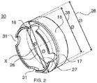
- La
figure 2 représente schématiquement un mode de réalisation d'une bague 30 anti-double alimentation selon l'invention. La bague 30 convient pour une munition 11 ayant un diamètre nominal 12 et un diamètre de tête 22. La munition 11 est destinée à être insérée dans un tube 13 s'étendant selon un axe X, le tube 13 comprenant une extrémité de sortie 14 ayant un premier diamètre intérieur 15. Selon l'invention, la bague 30 comprend : - a. Une première surface 16 circulaire de fixation ayant un diamètre intérieur 26 inférieur au diamètre de tête 22 de la munition 11;
- b. Une deuxième surface 17 circulaire ayant un diamètre extérieur 27 supérieur au premier diamètre intérieur 15 de l'extrémité de sortie 14 du tube 13;
- c. Une troisième surface 18 circulaire ayant un diamètre extérieur 28 sensiblement inférieur au premier diamètre intérieur 15 de l'extrémité de sortie 14 du tube 13 et un diamètre intérieur 38 sensiblement égal au diamètre de tête 22 de la munition 11, la bague étant symétrique et configurée pour que la troisième surface 18 soit disposée de manière centrée autour de l'axe X lorsque la munition 11 est insérée dans le tube 13.
- La première surface 16 a une forme géométrique circulaire permettant le clipsage de la bague selon l'invention sur la munition 11. Dans l'exemple représenté, la munition comprend une forme d'ogive au niveau de la tête, et la première surface 16 est configurée pour épouser la forme de la munition 11 au niveau de la tête. Le diamètre intérieur 26 est inférieur au diamètre de tête 22. En outre, le clipsage de la bague sur la munition 11 rend la bague solidaire de la munition 11. Cela permet à un servant de manipuler la munition 11 au niveau de la bague, sans risque de glissement de la munition.
- La première surface 16 est reliée à la deuxième surface 17. La deuxième surface 17 a un diamètre extérieur 27 supérieur au diamètre intérieur 15 de la bouche du tube 13 et a pour rôle de positionner la bague sur la bouche du tube 13. En d'autres termes, la deuxième surface 17 permet la mise en butée de la bague sur le tube 13. Comme la bague est clipsée sur la munition, la mise en butée de la bague à l'extrémité de sortie 14 du tube 13 se fait lors de l'insertion de la munition 11 dans le tube 13.
- La deuxième surface 17 se poursuit ensuite sur une forme profilée dont le diamètre se réduit. La deuxième surface 17 est reliée à la troisième surface 18. La troisième surface 18 a un diamètre extérieur 28 sensiblement inférieur au premier diamètre intérieur 15 de l'extrémité de sortie 14 du tube 13. Ce diamètre extérieur 28 est inférieur au premier diamètre intérieur 15 pour permettre l'insertion de cette portion de bague dans le tube 13. La troisième surface 18 contribue au guidage de la bague dans le tube 13. Cette surface permet donc le bon positionnement de la bague dans le tube 13. En effet, si la bague est mal positionnée, c'est-à-dire si son axe X n'est pas sensiblement perpendiculaire à la section de bouche du tube 13, il peut en résulter un blocage de la bague dans le tube 13 ou une éjection prématurée de la bague. En outre, la troisième surface 18 a un diamètre intérieur 38 sensiblement égal au diamètre de tête 22 de la munition 11. Cela permet à la troisième surface 18 d'épouser la forme de la munition11. Il y a peu de jeu entre la munition et le diamètre intérieur 38 de la troisième surface 18. La bague est symétrique et avec la troisième surface 18 centrée autour de l'axe X. Autrement dit, la bague est symétrique et centrée autour de son axe X confondu avec l'axe X du tube une fois que la bague est en position au niveau de la bouche du tube. La bague est ainsi positionnée de manière symétrique autour du tube. Ce bon positionnement de la bague évite à la bague de rester bloquée en sortie du tube 13 ou une éjection prématurée de la bague.
- Avantageusement, le diamètre intérieur 38 de la troisième surface 18 est compris entre 100 % et 101 % du diamètre de tête 22 de la munition 11.
- Une fois mise en butée au niveau de sa deuxième surface 17, la munition 11 descend par gravité dans le tube 13 et seule la bague reste positionnée en sortie du tube 13. En effet, la munition est soumise à son poids. Cette force est supérieure à celle exercée par la bague sur le pourtour de la munition 11 où la bague est clipsée. La munition tombe et la bague est déclipsée de la munition. Comme la munition 11 est engagée dans le tube 13, il en résulte un déplacement de la munition dans le tube 13. La bague, quant à elle, reste à l'extrémité de sortie 14 du tube 13, comme représenté à la
figure 4 . Autrement dit, la bague, initialement destinée à être positionnée autour de la munition lors de son transport et jusqu'à la mise en position de la munition dans le tube, se sépare de la munition pour rester clipsée à l'extrémité de sortie du tube. - Après le chargement de la première munition 11, la bague demeure en sortie de bouche du tube 13. Elle constitue désormais un obstacle pour l'insertion d'une deuxième munition. En effet, la première surface 16 a un diamètre intérieur 26 inférieur au diamètre de tête 22 de la munition 11 (et donc au diamètre nominal de la munition). Il est donc impossible d'insérer une deuxième munition par erreur.
- Dans un mode de réalisation, la bague est en matériau thermoplastique. Cela confère à la bague un bon compromis en termes de raideur et souplesse. En effet, il faut que la bague soit suffisamment souple pour être mise en place sur la munition et suffisamment raide pour être solidaire de la munition. Le matériau thermoplastique permet d'exercer sur la bague un effort de montage permettant à la bague de rester à poste sur le corps de la munition et ainsi permettant la préhension de la munition par les servants. De plus, grâce au matériau thermoplastique, son déclipsage est simple, ce qui permet à la bague de se positionner à la bouche de sortie du tube lors de l'insertion de la munition dans le tube. Le choix du matériau thermoplastique se fait de sorte à ce que la bague soit opérationnelle sur une large plage d'élasticité nécessaire et qui varie avec les températures.
- Sur la
figure 2 , la première surface 16 comprend au moins une encoche 31. Par encoche, on entend une ouverture dans la surface depuis son extrémité extérieure sensiblement normale à cette surface. Autrement dit, l'encoche 31 s'étend dans un sens sensiblement perpendiculaire à un diamètre de la première surface 16. Sur lafigure 2 , la bague 30 comprend quatre encoches 31 disposées sur la première surface 16. Selon l'invention, la bague peut comporter une, deux, trois encoches 31, ou même plus. Leur disposition dans la première surface 16 peut être quelconque. Avantageusement, les encoches 31 sont réparties à équidistance l'une de l'autre. A noter que l'invention concerne aussi la bague 10 ne présentant aucune encoche. Les encoches 31 facilitent le déclipsage de la bague 30. En effet, les ouvertures ainsi réalisées sur la première surface 16 diminuent la raideur de la bague 30 et la surface de contact entre la bague 30 et la munition. - La
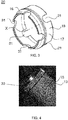
figure 3 représente schématiquement un deuxième mode de réalisation d'une bague 20 anti-double alimentation selon l'invention. La bague 20 comprend les mêmes éléments que la bague 10. En plus, la troisième surface 18 de la bague 20 comprend au moins une encoche 21. Par encoche, on entend une ouverture dans la surface depuis son extrémité extérieure sensiblement normale à cette surface. Autrement dit, l'encoche 21 s'étend dans un sens sensiblement perpendiculaire à un diamètre de la troisième surface 18. Sur lafigure 3 , la bague 20 comprend trois encoches 21 disposées sur la troisième surface 18. Selon l'invention, la bague peut comporter une, deux, trois encoches 21, ou même plus. Leur disposition dans la troisième surface 18 peut être quelconque. Avantageusement, les encoches 21 sont réparties à équidistance l'une de l'autre. A noter que l'invention concerne aussi une bague avec des encoches 21 sur la troisième surface 18 et sans encoche 31 sur la première surface 16. Les encoches 21 permettent d'assouplir la bague 20 et facilitent le positionnement de la bague 20 sur la munition. - On peut noter sur la
figure 3 que les encoches 21 sur la troisième surface 18 et les encoches 31 sur la première surface 16 ont des formes géométriques différentes. Le principe de l'invention s'applique aussi à des encoches 21, 31 ayant également la même géométrie. Les géométries différentes et spécifiques des encoches 21, 31 peuvent être déterminées par un Homme du métier afin d'obtenir un bon compromis de souplesse et de bon comportement pour le bon fonctionnement de la bague. - La
figure 4 représente schématiquement un tube 13 canon à l'extrémité duquel demeure la bague 30 selon l'invention. Comme expliqué précédemment, la bague 30 reste à l'extrémité de sortie 14 du tube 13, après l'insertion de la munition 11 dans le tube 13, même après la descente de la munition 11 dans le tube 13. Après le chargement de la première munition 11, la bague 30 demeure en sortie de bouche du tube 13. Elle constitue désormais un obstacle pour l'insertion d'une deuxième munition. En effet, la première surface 16 a un diamètre intérieur 26 inférieur au diamètre de tête 22 de la munition 11 (et donc au diamètre nominal de la munition). Il est donc impossible d'insérer une deuxième munition par erreur. La bague selon l'invention interdit physiquement l'insertion d'une deuxième munition suite à l'insertion d'une première munition dans le tube afin de garantir la sécurité des servants. - La
figure 5 représente schématiquement les étapes d'un procédé de mise en place d'une munition 11 comprenant une bague 10 selon l'invention dans un tube 13 canon. Le procédé de mise en place d'une munition 11 dans un tube 13 comprenant une extrémité de sortie 14, ladite munition 11 comprenant une bague 10, comprend une étape 110 d'insertion d'une extrémité de la munition 11 dans l'extrémité de sortie 14 du tube 13. A ce stade, la bague 10 est positionnée sur la munition 11. Elle y est clipsée et est solidaire de la munition 11. - Puis le procédé selon l'invention comprend une étape 120 de guidage de la bague 10 dans l'extrémité de sortie 14 du tube 13 et disposition de la troisième surface 18 de la bague de manière centrée autour de l'axe X lorsque la munition 11 est insérée dans le tube 13. Cette étape de guidage est rendue possible grâce à la troisième surface 18 de la bague 10 qui offre un jeu minimum entre le diamètre intérieur du tube 13 et la bague elle-même (plus précisément le diamètre extérieur 28 de la troisième surface 18). En outre, la bague de forme symétrique et avec la troisième surface 18 centrée autour de l'axe X permet de garantir le bon positionnement de la bague, c'est-à-dire que son axe X (confondu avec l'axe X du tube) est sensiblement perpendiculaire à la section de bouche du tube 13. Cela évite tout blocage de la bague dans le tube 13 ou une éjection prématurée de la bague.
- Le procédé selon l'invention comprend ensuite une étape 130 de mise en butée de la deuxième surface 17 sur l'extrémité de sortie 14 du tube 13. La deuxième surface 17 de la bague 10 vient en contact de la bouche du tube 13. Le diamètre 27 de la deuxième surface 17 étant plus grand que le diamètre intérieur 15 du tube 13, la bague est stoppée au niveau de sa deuxième surface 17 à l'extrémité de sortie 14 du tube 13.
- S'ensuite une étape 140 de descente par gravité de la munition 11 dans le tube 13. Le procédé comprend alors une étape 150 de déclipsage de la bague 10 de la munition 11. En effet, le tube 13 étant typiquement incliné, le poids de la munition 11 suffit à déclipser la bague 10 qui reste à l'extrémité de sortie 14 du tube 13. Cela permet ainsi d'éviter l'insertion d'une autre munition dans le tube 13.
- Dans la suite, le procédé selon l'invention peut comprendre une étape 160 de tir de la munition 11 produisant des gaz, puis une étape 170 d'éjection de la bague 10 par les gaz générés. Une fois que la bague 10 a été éjectée par les gaz générés lors du tir, l'introduction d'une autre munition 11 est possible, tout en étant assuré que le tube 13 est vide de munition.
- Préalablement à l'étape 110 d'insertion d'une extrémité de la munition 11 dans l'extrémité de sortie 14 du tube 13, le procédé peut comprendre une étape 100 de clipsage de la bague 10 sur la munition 11. Ainsi la bague selon l'invention est positionnée à poste sur la munition et ne se déclipse que lors de l'insertion de la munition dans le tube. Cela signifie que l'utilisation de cette bague est transparente pour les servants vis-à-vis des opérations habituelles.
- La bague double alimentation selon l'invention présente de nombreux avantages. Le fonctionnement nominal de la munition n'est pas perturbé. La bague permet de garantir la sécurité des servants en empêchant une double alimentation dans le tube canon. La bague est avantageusement intégrée à poste sur la munition lors de la production de la munition. Il en résulte que son utilisation sur une munition est transparente pour les servants. Comme la bague est expulsée par les gaz générés lors du tir, les servants n'ont pas à manipuler la bague, même après le tir. La transparence dans l'utilisation est complète. Enfin, la bague est compatible du calibre 81 mm sans distinction du type de munition. De plus le principe de la bague peut être adapté à tout diamètre de tube et munition. Un autre avantage de l'invention est que la bague ne nécessite aucune modification des systèmes d'arme existants.
Claims (9)
- Bague (10, 20, 30) pour munition (11) ayant un diamètre nominal (12) et un diamètre de tête (22), la munition (11) ayant un corps, ladite munition (11) étant destinée à être insérée dans un tube (13) s'étendant selon un axe X, le tube (13) comprenant une extrémité de sortie (14) ayant un premier diamètre intérieur (15), ladite bague (10) étant destinée à être positionnée autour du corps de la munition (11), ladite bague (10) étant caractérisée en ce qu'elle comprend :a. Une première surface (16) circulaire de fixation sur la munition (11) ayant un diamètre intérieur (26) inférieur au diamètre de tête (22) de la munition (11);b. Une deuxième surface (17) circulaire ayant un diamètre extérieur (27) supérieur au premier diamètre intérieur (15) de l'extrémité de sortie (14) du tube (13);c. Une troisième surface (18) circulaire ayant un diamètre extérieur (28) sensiblement inférieur au premier diamètre intérieur (15) de l'extrémité de sortie (14) du tube (13) et un diamètre intérieur (38) sensiblement égal au diamètre de tête (22) de la munition (11) ;et en ce que la bague est symétrique et configurée pour que la troisième surface (18) soit disposée de manière centrée autour de l'axe X lorsque la munition (11) est insérée dans le tube (13).
- Bague (10, 20, 30) selon la revendication 1, caractérisée en ce qu'elle est en matériau thermoplastique.
- Bague (20) selon l'une quelconque des revendications 1 ou 2, caractérisée en ce que la troisième surface (18) comprend au moins une encoche (21).
- Bague (30) selon l'une quelconque des revendications 2 ou 3, caractérisée en ce que la première surface (16) comprend au moins une encoche (31).
- Bague (10, 20, 30) selon l'une quelconque des revendications 1 à 4, caractérisée en ce que le diamètre intérieur (38) de la troisième surface (18) est compris entre 100 % et 101 % du diamètre de tête (22) de la munition (11).
- Ensemble (50) comprenant :a. une munition (11) ayant un diamètre nominal (12) et un diamètre de tête (22), la munition (11) ayant un corps, ladite munition (11) étant destinée à être insérée dans un tube (13) s'étendant selon un axe X, le tube (13) comprenant une extrémité de sortie (14) ayant un premier diamètre intérieur (15) ;b. Une bague (10, 20, 30) selon l'une quelconque des revendications 1 à 5, la bague étant positionnée autour du corps de la munition.
- Procédé de mise en place d'une munition (11) dans un tube (13) s'étendant selon un axe X, le tube (13) comprenant une extrémité de sortie (14), ladite munition (11) comprenant une bague (10, 20, 30) selon l'une quelconque des revendications 1 à 5, ledit procédé étant caractérisé en ce qu'il comprend les étapes suivantes:a. Insertion (110) d'une extrémité de la munition (11) dans l'extrémité de sortie (14) du tube (13) ;b. Guidage (120) de la bague (10, 20, 30) dans l'extrémité de sortie (14) du tube (13) et disposition de la troisième surface (18) de la bague de manière centrée autour de l'axe X lorsque la munition (11) est insérée dans le tube (13);c. Mise en butée (130) de la deuxième surface (17) sur l'extrémité de sortie (14) du tube (13) ;d. Descente (140) par gravité de la munition (11) dans le tube (13) ;e. Déclipsage (150) de la bague (10, 20, 30) de la munition (11).
- Procédé selon la revendication 7, comprenant en outre les étapes suivantes :a. Tir (160) de la munition (11) produisant des gaz ;b. Ejection (170) de la bague (10, 20, 30) par les gaz générés.
- Procédé selon l'une quelconque des revendications 7 ou 8, comprenant préalablement à l'étape (110) d'insertion d'une extrémité de la munition (11) dans l'extrémité de sortie (14) du tube (13) une étape (100) de clipsage de la bague (10, 20, 30) sur la munition (11).
Applications Claiming Priority (1)
| Application Number | Priority Date | Filing Date | Title |
|---|---|---|---|
| FR2004744A FR3110229B1 (fr) | 2020-05-14 | 2020-05-14 | Bague Anti-Double Alimentation |
Publications (2)
| Publication Number | Publication Date |
|---|---|
| EP3910277A1 true EP3910277A1 (fr) | 2021-11-17 |
| EP3910277B1 EP3910277B1 (fr) | 2024-06-05 |
Family
ID=73138871
Family Applications (1)
| Application Number | Title | Priority Date | Filing Date |
|---|---|---|---|
| EP21173534.5A Active EP3910277B1 (fr) | 2020-05-14 | 2021-05-12 | Bague anti-double alimentation |
Country Status (4)
| Country | Link |
|---|---|
| EP (1) | EP3910277B1 (fr) |
| FR (1) | FR3110229B1 (fr) |
| IL (1) | IL283035B2 (fr) |
| ZA (1) | ZA202103235B (fr) |
Citations (3)
| Publication number | Priority date | Publication date | Assignee | Title |
|---|---|---|---|---|
| FR1178002A (fr) * | 1957-06-27 | 1959-05-04 | F E R E | Perfectionnements aux munitions des matériels d'armement |
| US3698282A (en) * | 1971-06-23 | 1972-10-17 | Us Navy | Mortar safety device for preventing double loading |
| EP2894429A1 (fr) * | 2014-01-08 | 2015-07-15 | KMS Consulting LLC | Dispositif de sécurité de mortier |
-
2020
- 2020-05-14 FR FR2004744A patent/FR3110229B1/fr not_active Expired - Fee Related
-
2021
- 2021-05-09 IL IL283035A patent/IL283035B2/en unknown
- 2021-05-12 EP EP21173534.5A patent/EP3910277B1/fr active Active
- 2021-05-13 ZA ZA2021/03235A patent/ZA202103235B/en unknown
Patent Citations (3)
| Publication number | Priority date | Publication date | Assignee | Title |
|---|---|---|---|---|
| FR1178002A (fr) * | 1957-06-27 | 1959-05-04 | F E R E | Perfectionnements aux munitions des matériels d'armement |
| US3698282A (en) * | 1971-06-23 | 1972-10-17 | Us Navy | Mortar safety device for preventing double loading |
| EP2894429A1 (fr) * | 2014-01-08 | 2015-07-15 | KMS Consulting LLC | Dispositif de sécurité de mortier |
Also Published As
| Publication number | Publication date |
|---|---|
| EP3910277B1 (fr) | 2024-06-05 |
| ZA202103235B (en) | 2022-04-28 |
| IL283035B1 (en) | 2025-04-01 |
| FR3110229B1 (fr) | 2022-07-15 |
| FR3110229A1 (fr) | 2021-11-19 |
| IL283035B2 (en) | 2025-08-01 |
| IL283035A (en) | 2021-12-01 |
Similar Documents
| Publication | Publication Date | Title |
|---|---|---|
| EP1092940B1 (fr) | Dispositif d'allumage pour un chargement propulsif | |
| EP0307307B1 (fr) | Bague de liaison entre un projectile et une douille | |
| EP0572643B1 (fr) | Tube douille pour grenade a fusil pouvant retenir les fragments de la balle | |
| FR2679993A1 (fr) | Munition, en particulier du type telescope. | |
| EP3715776B1 (fr) | Cartouche comprenant des cordeaux d'allumage | |
| EP0401115B1 (fr) | Dispositif de maintien d'un projectile sous calibré relativement à l'enveloppe d'une munition télescopée | |
| EP3910277B1 (fr) | Bague anti-double alimentation | |
| FR2864219A1 (fr) | Dispositif de deconfinement d'une enveloppe de munition | |
| FR2806789A1 (fr) | Tube allumeur pour une munition d'artillerie | |
| EP1650525B1 (fr) | Dispositif de tir | |
| EP0541412B1 (fr) | Obus cargo éjectant une charge utile au moyen d'un piston | |
| EP0659264B1 (fr) | Dispositif d'etancheite aux gaz de propulsion pour munitions d'artillerie | |
| EP0594482B1 (fr) | Boîtier pour charge propulsive | |
| EP0108013A1 (fr) | Dispositif et projectile déclencheurs d'avalanches | |
| FR2671622A1 (fr) | Projectile avec coiffe rapportee. | |
| EP0775887B1 (fr) | Arrêtoir pour un étui de charge explosive | |
| EP2620737B1 (fr) | Munition non létale | |
| FR2884603A1 (fr) | Dispositif d'adaptation d'un obus de mortier dans un canon | |
| FR2680568A1 (fr) | Cartouche d'exercice et tube pour cartouche d'exercice. | |
| EP0526316B1 (fr) | Munition en particulier du type télescopé | |
| EP1693645B1 (fr) | Projectile d'artillerie comportant une ceinture | |
| CH687274A5 (fr) | Projectile muni d'un dispositif de mise sous sûreté et d'armement. | |
| FR2635178A1 (fr) | Dispositif d'ouverture d'empennage pour obus | |
| EP4141373B1 (fr) | Système de contrôle de la mise à poste d'un projectile dans un tube d'arme et procédé de contrôle mis en oeuvre par un tel système | |
| EP0724132A1 (fr) | Dispositif de sécurité et d'armement pour fusée de projectile |
Legal Events
| Date | Code | Title | Description |
|---|---|---|---|
| PUAI | Public reference made under article 153(3) epc to a published international application that has entered the european phase |
Free format text: ORIGINAL CODE: 0009012 |
|
| STAA | Information on the status of an ep patent application or granted ep patent |
Free format text: STATUS: THE APPLICATION HAS BEEN PUBLISHED |
|
| AK | Designated contracting states |
Kind code of ref document: A1 Designated state(s): AL AT BE BG CH CY CZ DE DK EE ES FI FR GB GR HR HU IE IS IT LI LT LU LV MC MK MT NL NO PL PT RO RS SE SI SK SM TR |
|
| B565 | Issuance of search results under rule 164(2) epc |
Effective date: 20210924 |
|
| STAA | Information on the status of an ep patent application or granted ep patent |
Free format text: STATUS: REQUEST FOR EXAMINATION WAS MADE |
|
| 17P | Request for examination filed |
Effective date: 20220204 |
|
| RBV | Designated contracting states (corrected) |
Designated state(s): AL AT BE BG CH CY CZ DE DK EE ES FI FR GB GR HR HU IE IS IT LI LT LU LV MC MK MT NL NO PL PT RO RS SE SI SK SM TR |
|
| P01 | Opt-out of the competence of the unified patent court (upc) registered |
Effective date: 20230516 |
|
| GRAP | Despatch of communication of intention to grant a patent |
Free format text: ORIGINAL CODE: EPIDOSNIGR1 |
|
| STAA | Information on the status of an ep patent application or granted ep patent |
Free format text: STATUS: GRANT OF PATENT IS INTENDED |
|
| INTG | Intention to grant announced |
Effective date: 20240227 |
|
| GRAS | Grant fee paid |
Free format text: ORIGINAL CODE: EPIDOSNIGR3 |
|
| GRAA | (expected) grant |
Free format text: ORIGINAL CODE: 0009210 |
|
| STAA | Information on the status of an ep patent application or granted ep patent |
Free format text: STATUS: THE PATENT HAS BEEN GRANTED |
|
| RAP3 | Party data changed (applicant data changed or rights of an application transferred) |
Owner name: THALES |
|
| AK | Designated contracting states |
Kind code of ref document: B1 Designated state(s): AL AT BE BG CH CY CZ DE DK EE ES FI FR GB GR HR HU IE IS IT LI LT LU LV MC MK MT NL NO PL PT RO RS SE SI SK SM TR |
|
| REG | Reference to a national code |
Ref country code: CH Ref legal event code: EP |
|
| REG | Reference to a national code |
Ref country code: DE Ref legal event code: R096 Ref document number: 602021013989 Country of ref document: DE |
|
| REG | Reference to a national code |
Ref country code: IE Ref legal event code: FG4D Free format text: LANGUAGE OF EP DOCUMENT: FRENCH |
|
| REG | Reference to a national code |
Ref country code: LT Ref legal event code: MG9D |
|
| PG25 | Lapsed in a contracting state [announced via postgrant information from national office to epo] |
Ref country code: BG Free format text: LAPSE BECAUSE OF FAILURE TO SUBMIT A TRANSLATION OF THE DESCRIPTION OR TO PAY THE FEE WITHIN THE PRESCRIBED TIME-LIMIT Effective date: 20240605 |
|
| REG | Reference to a national code |
Ref country code: NL Ref legal event code: MP Effective date: 20240605 |
|
| PG25 | Lapsed in a contracting state [announced via postgrant information from national office to epo] |
Ref country code: FI Free format text: LAPSE BECAUSE OF FAILURE TO SUBMIT A TRANSLATION OF THE DESCRIPTION OR TO PAY THE FEE WITHIN THE PRESCRIBED TIME-LIMIT Effective date: 20240605 Ref country code: HR Free format text: LAPSE BECAUSE OF FAILURE TO SUBMIT A TRANSLATION OF THE DESCRIPTION OR TO PAY THE FEE WITHIN THE PRESCRIBED TIME-LIMIT Effective date: 20240605 |
|
| PG25 | Lapsed in a contracting state [announced via postgrant information from national office to epo] |
Ref country code: GR Free format text: LAPSE BECAUSE OF FAILURE TO SUBMIT A TRANSLATION OF THE DESCRIPTION OR TO PAY THE FEE WITHIN THE PRESCRIBED TIME-LIMIT Effective date: 20240906 |
|
| PG25 | Lapsed in a contracting state [announced via postgrant information from national office to epo] |
Ref country code: ES Free format text: LAPSE BECAUSE OF FAILURE TO SUBMIT A TRANSLATION OF THE DESCRIPTION OR TO PAY THE FEE WITHIN THE PRESCRIBED TIME-LIMIT Effective date: 20240605 |
|
| PG25 | Lapsed in a contracting state [announced via postgrant information from national office to epo] |
Ref country code: LV Free format text: LAPSE BECAUSE OF FAILURE TO SUBMIT A TRANSLATION OF THE DESCRIPTION OR TO PAY THE FEE WITHIN THE PRESCRIBED TIME-LIMIT Effective date: 20240605 |
|
| PG25 | Lapsed in a contracting state [announced via postgrant information from national office to epo] |
Ref country code: NO Free format text: LAPSE BECAUSE OF FAILURE TO SUBMIT A TRANSLATION OF THE DESCRIPTION OR TO PAY THE FEE WITHIN THE PRESCRIBED TIME-LIMIT Effective date: 20240905 Ref country code: LV Free format text: LAPSE BECAUSE OF FAILURE TO SUBMIT A TRANSLATION OF THE DESCRIPTION OR TO PAY THE FEE WITHIN THE PRESCRIBED TIME-LIMIT Effective date: 20240605 Ref country code: HR Free format text: LAPSE BECAUSE OF FAILURE TO SUBMIT A TRANSLATION OF THE DESCRIPTION OR TO PAY THE FEE WITHIN THE PRESCRIBED TIME-LIMIT Effective date: 20240605 Ref country code: GR Free format text: LAPSE BECAUSE OF FAILURE TO SUBMIT A TRANSLATION OF THE DESCRIPTION OR TO PAY THE FEE WITHIN THE PRESCRIBED TIME-LIMIT Effective date: 20240906 Ref country code: FI Free format text: LAPSE BECAUSE OF FAILURE TO SUBMIT A TRANSLATION OF THE DESCRIPTION OR TO PAY THE FEE WITHIN THE PRESCRIBED TIME-LIMIT Effective date: 20240605 Ref country code: ES Free format text: LAPSE BECAUSE OF FAILURE TO SUBMIT A TRANSLATION OF THE DESCRIPTION OR TO PAY THE FEE WITHIN THE PRESCRIBED TIME-LIMIT Effective date: 20240605 Ref country code: BG Free format text: LAPSE BECAUSE OF FAILURE TO SUBMIT A TRANSLATION OF THE DESCRIPTION OR TO PAY THE FEE WITHIN THE PRESCRIBED TIME-LIMIT Effective date: 20240605 Ref country code: RS Free format text: LAPSE BECAUSE OF FAILURE TO SUBMIT A TRANSLATION OF THE DESCRIPTION OR TO PAY THE FEE WITHIN THE PRESCRIBED TIME-LIMIT Effective date: 20240905 |
|
| PG25 | Lapsed in a contracting state [announced via postgrant information from national office to epo] |
Ref country code: NL Free format text: LAPSE BECAUSE OF FAILURE TO SUBMIT A TRANSLATION OF THE DESCRIPTION OR TO PAY THE FEE WITHIN THE PRESCRIBED TIME-LIMIT Effective date: 20240605 |
|
| REG | Reference to a national code |
Ref country code: AT Ref legal event code: MK05 Ref document number: 1692743 Country of ref document: AT Kind code of ref document: T Effective date: 20240605 |
|
| PG25 | Lapsed in a contracting state [announced via postgrant information from national office to epo] |
Ref country code: NL Free format text: LAPSE BECAUSE OF FAILURE TO SUBMIT A TRANSLATION OF THE DESCRIPTION OR TO PAY THE FEE WITHIN THE PRESCRIBED TIME-LIMIT Effective date: 20240605 |
|
| PG25 | Lapsed in a contracting state [announced via postgrant information from national office to epo] |
Ref country code: PT Free format text: LAPSE BECAUSE OF FAILURE TO SUBMIT A TRANSLATION OF THE DESCRIPTION OR TO PAY THE FEE WITHIN THE PRESCRIBED TIME-LIMIT Effective date: 20241007 |
|
| PG25 | Lapsed in a contracting state [announced via postgrant information from national office to epo] |
Ref country code: PT Free format text: LAPSE BECAUSE OF FAILURE TO SUBMIT A TRANSLATION OF THE DESCRIPTION OR TO PAY THE FEE WITHIN THE PRESCRIBED TIME-LIMIT Effective date: 20241007 |
|
| PG25 | Lapsed in a contracting state [announced via postgrant information from national office to epo] |
Ref country code: PL Free format text: LAPSE BECAUSE OF FAILURE TO SUBMIT A TRANSLATION OF THE DESCRIPTION OR TO PAY THE FEE WITHIN THE PRESCRIBED TIME-LIMIT Effective date: 20240605 |
|
| PG25 | Lapsed in a contracting state [announced via postgrant information from national office to epo] |
Ref country code: EE Free format text: LAPSE BECAUSE OF FAILURE TO SUBMIT A TRANSLATION OF THE DESCRIPTION OR TO PAY THE FEE WITHIN THE PRESCRIBED TIME-LIMIT Effective date: 20240605 |
|
| PG25 | Lapsed in a contracting state [announced via postgrant information from national office to epo] |
Ref country code: AT Free format text: LAPSE BECAUSE OF FAILURE TO SUBMIT A TRANSLATION OF THE DESCRIPTION OR TO PAY THE FEE WITHIN THE PRESCRIBED TIME-LIMIT Effective date: 20240605 Ref country code: IS Free format text: LAPSE BECAUSE OF FAILURE TO SUBMIT A TRANSLATION OF THE DESCRIPTION OR TO PAY THE FEE WITHIN THE PRESCRIBED TIME-LIMIT Effective date: 20241005 |
|
| PG25 | Lapsed in a contracting state [announced via postgrant information from national office to epo] |
Ref country code: CZ Free format text: LAPSE BECAUSE OF FAILURE TO SUBMIT A TRANSLATION OF THE DESCRIPTION OR TO PAY THE FEE WITHIN THE PRESCRIBED TIME-LIMIT Effective date: 20240605 |
|
| PG25 | Lapsed in a contracting state [announced via postgrant information from national office to epo] |
Ref country code: SK Free format text: LAPSE BECAUSE OF FAILURE TO SUBMIT A TRANSLATION OF THE DESCRIPTION OR TO PAY THE FEE WITHIN THE PRESCRIBED TIME-LIMIT Effective date: 20240605 Ref country code: RO Free format text: LAPSE BECAUSE OF FAILURE TO SUBMIT A TRANSLATION OF THE DESCRIPTION OR TO PAY THE FEE WITHIN THE PRESCRIBED TIME-LIMIT Effective date: 20240605 |
|
| PG25 | Lapsed in a contracting state [announced via postgrant information from national office to epo] |
Ref country code: SM Free format text: LAPSE BECAUSE OF FAILURE TO SUBMIT A TRANSLATION OF THE DESCRIPTION OR TO PAY THE FEE WITHIN THE PRESCRIBED TIME-LIMIT Effective date: 20240605 |
|
| PG25 | Lapsed in a contracting state [announced via postgrant information from national office to epo] |
Ref country code: SM Free format text: LAPSE BECAUSE OF FAILURE TO SUBMIT A TRANSLATION OF THE DESCRIPTION OR TO PAY THE FEE WITHIN THE PRESCRIBED TIME-LIMIT Effective date: 20240605 Ref country code: SK Free format text: LAPSE BECAUSE OF FAILURE TO SUBMIT A TRANSLATION OF THE DESCRIPTION OR TO PAY THE FEE WITHIN THE PRESCRIBED TIME-LIMIT Effective date: 20240605 Ref country code: RO Free format text: LAPSE BECAUSE OF FAILURE TO SUBMIT A TRANSLATION OF THE DESCRIPTION OR TO PAY THE FEE WITHIN THE PRESCRIBED TIME-LIMIT Effective date: 20240605 Ref country code: PL Free format text: LAPSE BECAUSE OF FAILURE TO SUBMIT A TRANSLATION OF THE DESCRIPTION OR TO PAY THE FEE WITHIN THE PRESCRIBED TIME-LIMIT Effective date: 20240605 Ref country code: IS Free format text: LAPSE BECAUSE OF FAILURE TO SUBMIT A TRANSLATION OF THE DESCRIPTION OR TO PAY THE FEE WITHIN THE PRESCRIBED TIME-LIMIT Effective date: 20241005 Ref country code: EE Free format text: LAPSE BECAUSE OF FAILURE TO SUBMIT A TRANSLATION OF THE DESCRIPTION OR TO PAY THE FEE WITHIN THE PRESCRIBED TIME-LIMIT Effective date: 20240605 Ref country code: CZ Free format text: LAPSE BECAUSE OF FAILURE TO SUBMIT A TRANSLATION OF THE DESCRIPTION OR TO PAY THE FEE WITHIN THE PRESCRIBED TIME-LIMIT Effective date: 20240605 Ref country code: AT Free format text: LAPSE BECAUSE OF FAILURE TO SUBMIT A TRANSLATION OF THE DESCRIPTION OR TO PAY THE FEE WITHIN THE PRESCRIBED TIME-LIMIT Effective date: 20240605 |
|
| PG25 | Lapsed in a contracting state [announced via postgrant information from national office to epo] |
Ref country code: IT Free format text: LAPSE BECAUSE OF FAILURE TO SUBMIT A TRANSLATION OF THE DESCRIPTION OR TO PAY THE FEE WITHIN THE PRESCRIBED TIME-LIMIT Effective date: 20240605 |
|
| REG | Reference to a national code |
Ref country code: DE Ref legal event code: R097 Ref document number: 602021013989 Country of ref document: DE |
|
| PLBE | No opposition filed within time limit |
Free format text: ORIGINAL CODE: 0009261 |
|
| STAA | Information on the status of an ep patent application or granted ep patent |
Free format text: STATUS: NO OPPOSITION FILED WITHIN TIME LIMIT |
|
| PG25 | Lapsed in a contracting state [announced via postgrant information from national office to epo] |
Ref country code: DK Free format text: LAPSE BECAUSE OF FAILURE TO SUBMIT A TRANSLATION OF THE DESCRIPTION OR TO PAY THE FEE WITHIN THE PRESCRIBED TIME-LIMIT Effective date: 20240605 |
|
| 26N | No opposition filed |
Effective date: 20250306 |
|
| PGFP | Annual fee paid to national office [announced via postgrant information from national office to epo] |
Ref country code: BE Payment date: 20250422 Year of fee payment: 5 |
|
| PGFP | Annual fee paid to national office [announced via postgrant information from national office to epo] |
Ref country code: FR Payment date: 20250422 Year of fee payment: 5 |
|
| PG25 | Lapsed in a contracting state [announced via postgrant information from national office to epo] |
Ref country code: SE Free format text: LAPSE BECAUSE OF FAILURE TO SUBMIT A TRANSLATION OF THE DESCRIPTION OR TO PAY THE FEE WITHIN THE PRESCRIBED TIME-LIMIT Effective date: 20240605 |
|
| REG | Reference to a national code |
Ref country code: DE Ref legal event code: R119 Ref document number: 602021013989 Country of ref document: DE |
|
| REG | Reference to a national code |
Ref country code: CH Ref legal event code: H13 Free format text: ST27 STATUS EVENT CODE: U-0-0-H10-H13 (AS PROVIDED BY THE NATIONAL OFFICE) Effective date: 20251223 |
|
| PG25 | Lapsed in a contracting state [announced via postgrant information from national office to epo] |
Ref country code: LU Free format text: LAPSE BECAUSE OF NON-PAYMENT OF DUE FEES Effective date: 20250512 |
|
| PG25 | Lapsed in a contracting state [announced via postgrant information from national office to epo] |
Ref country code: CH Free format text: LAPSE BECAUSE OF NON-PAYMENT OF DUE FEES Effective date: 20250531 |
|
| GBPC | Gb: european patent ceased through non-payment of renewal fee |
Effective date: 20250512 |
|
| PG25 | Lapsed in a contracting state [announced via postgrant information from national office to epo] |
Ref country code: MC Free format text: LAPSE BECAUSE OF FAILURE TO SUBMIT A TRANSLATION OF THE DESCRIPTION OR TO PAY THE FEE WITHIN THE PRESCRIBED TIME-LIMIT Effective date: 20240605 |
|
| PG25 | Lapsed in a contracting state [announced via postgrant information from national office to epo] |
Ref country code: GB Free format text: LAPSE BECAUSE OF NON-PAYMENT OF DUE FEES Effective date: 20250512 |
|
| PG25 | Lapsed in a contracting state [announced via postgrant information from national office to epo] |
Ref country code: IE Free format text: LAPSE BECAUSE OF NON-PAYMENT OF DUE FEES Effective date: 20250512 Ref country code: DE Free format text: LAPSE BECAUSE OF NON-PAYMENT OF DUE FEES Effective date: 20251202 |