EP3910137A1 - Vehicle door handle assembly - Google Patents
Vehicle door handle assembly Download PDFInfo
- Publication number
- EP3910137A1 EP3910137A1 EP21173436.3A EP21173436A EP3910137A1 EP 3910137 A1 EP3910137 A1 EP 3910137A1 EP 21173436 A EP21173436 A EP 21173436A EP 3910137 A1 EP3910137 A1 EP 3910137A1
- Authority
- EP
- European Patent Office
- Prior art keywords
- handle
- plunger
- housing
- compression mechanism
- biasing member
- Prior art date
- Legal status (The legal status is an assumption and is not a legal conclusion. Google has not performed a legal analysis and makes no representation as to the accuracy of the status listed.)
- Pending
Links
Images






Classifications
-
- E—FIXED CONSTRUCTIONS
- E05—LOCKS; KEYS; WINDOW OR DOOR FITTINGS; SAFES
- E05B—LOCKS; ACCESSORIES THEREFOR; HANDCUFFS
- E05B85/00—Details of vehicle locks not provided for in groups E05B77/00 - E05B83/00
- E05B85/10—Handles
- E05B85/103—Handles creating a completely closed wing surface
-
- E—FIXED CONSTRUCTIONS
- E05—LOCKS; KEYS; WINDOW OR DOOR FITTINGS; SAFES
- E05B—LOCKS; ACCESSORIES THEREFOR; HANDCUFFS
- E05B85/00—Details of vehicle locks not provided for in groups E05B77/00 - E05B83/00
- E05B85/10—Handles
- E05B85/107—Pop-out handles, e.g. sliding outwardly before rotation
-
- E—FIXED CONSTRUCTIONS
- E05—LOCKS; KEYS; WINDOW OR DOOR FITTINGS; SAFES
- E05B—LOCKS; ACCESSORIES THEREFOR; HANDCUFFS
- E05B77/00—Vehicle locks characterised by special functions or purposes
- E05B77/34—Protection against weather or dirt, e.g. against water ingress
-
- E—FIXED CONSTRUCTIONS
- E05—LOCKS; KEYS; WINDOW OR DOOR FITTINGS; SAFES
- E05B—LOCKS; ACCESSORIES THEREFOR; HANDCUFFS
- E05B85/00—Details of vehicle locks not provided for in groups E05B77/00 - E05B83/00
- E05B85/10—Handles
- E05B85/14—Handles pivoted about an axis parallel to the wing
- E05B85/16—Handles pivoted about an axis parallel to the wing a longitudinal grip part being pivoted at one end about an axis perpendicular to the longitudinal axis of the grip part
-
- E—FIXED CONSTRUCTIONS
- E05—LOCKS; KEYS; WINDOW OR DOOR FITTINGS; SAFES
- E05B—LOCKS; ACCESSORIES THEREFOR; HANDCUFFS
- E05B79/00—Mounting or connecting vehicle locks or parts thereof
- E05B79/02—Mounting of vehicle locks or parts thereof
- E05B79/06—Mounting of handles, e.g. to the wing or to the lock
-
- E—FIXED CONSTRUCTIONS
- E05—LOCKS; KEYS; WINDOW OR DOOR FITTINGS; SAFES
- E05Y—INDEXING SCHEME ASSOCIATED WITH SUBCLASSES E05D AND E05F, RELATING TO CONSTRUCTION ELEMENTS, ELECTRIC CONTROL, POWER SUPPLY, POWER SIGNAL OR TRANSMISSION, USER INTERFACES, MOUNTING OR COUPLING, DETAILS, ACCESSORIES, AUXILIARY OPERATIONS NOT OTHERWISE PROVIDED FOR, APPLICATION THEREOF
- E05Y2900/00—Application of doors, windows, wings or fittings thereof
- E05Y2900/50—Application of doors, windows, wings or fittings thereof for vehicles
- E05Y2900/53—Type of wing
- E05Y2900/531—Doors
Definitions
- the present disclosure relates generally to vehicle door handle assemblies.
- Some vehicles such as automobiles, include door handles that are substantially flush with an outer surface of the vehicle body, e.g., a door panel.
- the door handle may be moved to an extended or ready position relative to the vehicle body, such that a user may grasp the handle and open the door.
- a layer of ice may form on the vehicle body, including over the door handle. In such situations, it may be difficult for the door handle to be moved to the extended position due to the ice freezing over the door handle and the vehicle body.
- the door handle assembly may include a housing, a handle, and a compression mechanism.
- the handle may be rotatably attached to the housing and rotatable between a resting position and a depressed position.
- the compression mechanism may be configured to allow rotation of the handle between the resting position and the depressed position.
- the compression mechanism may include a plunger and a biasing member.
- the plunger may be coupled to one of the housing or the handle and translatable between a first position when the handle is in the resting position and a second position when the handle is in the depressed position.
- the biasing member may be coupled to one of the housing or the handle and configured to bias the plunger between the first position and the second position.
- the handle extends from a proximal end to a distal end.
- the handle may be rotatably attached to the housing at a location closer to the proximal end than the distal end.
- the handle at or near the distal end may urge the plunger to the second position and the biasing member to a compressed position.
- the handle may be configured to rotate from the resting position to the depressed position by a user exerting a force upon the handle at or near the distal end.
- the handle may be configured to rotate to an extended position where the handle is spaced from the plunger by a user exerting a force upon the handle at or near the proximal end.
- an outer surface of the handle is substantially parallel to an outer surface of the housing.
- the compression mechanism further includes a damper secured to the plunger and configured to engage the handle.
- the plunger may include a central bore.
- the damper may be disposed in the central bore.
- the compression mechanism further includes a plunger housing coupled to the housing and configured to receive the plunger and the biasing member.
- the plunger housing may include at least one tab.
- the housing may include at least one slot configured to receive the at least one tab to secure the plunger housing to the housing.
- the handle is rotatable about a first axis and the biasing member is compressible along a second axis perpendicular to the first axis.
- the compression mechanism may include a plunger and a biasing member.
- the plunger may be disposed adjacent the handle and translatable between a first position when the handle is in the resting position and a second position when the handle is in the depressed position.
- the biasing member may be disposed adjacent the plunger and compressible between a third position when the handle is in the resting position and a fourth position when the handle is in the depressed position.
- a damper is secured to the plunger and engaged with the handle.
- the plunger may include a central bore.
- the damper may be disposed in the central bore.
- the biasing member may define a central cavity. The damper and the plunger may extend into the central cavity.
- the compression mechanism includes a plunger housing configured to receive the plunger and the biasing member.
- the biasing member compresses from the third position to the fourth position by the plunger exerting a force upon the biasing member.
- Yet another aspect of the disclosure provides a method for operating a door handle assembly for a vehicle.
- the method may include exerting a first force upon a distal end of a handle to move the distal end toward the vehicle.
- the method may also include removing the first force upon the distal end of the handle to allow the handle to return to a resting position.
- Implementations of the disclosure may include one or more of the following optional features.
- the method includes exerting a second force upon a proximal end of the handle to move the handle toward an extended position.
- the method includes applying a second force upon the distal end while moving the distal end toward the vehicle, the second force being opposite the first force.
- Example configurations will now be described more fully with reference to the accompanying drawings.
- Example configurations are provided so that this disclosure will be thorough, and will fully convey the scope of the disclosure to those of ordinary skill in the art. Specific details are set forth such as examples of specific components, devices, and methods, to provide a thorough understanding of configurations of the present disclosure. It will be apparent to those of ordinary skill in the art that specific details need not be employed, that example configurations may be embodied in many different forms, and that the specific details and the example configurations should not be construed to limit the scope of the disclosure.
- a door handle assembly 100 is generally shown.
- the door handle assembly 100 may be installed in or attached to a vehicle, such as a door panel 10 of a vehicle body of the vehicle.
- the door handle assembly 100 may be installed in a trunk door, a hood, or any other suitable location on a vehicle.
- the door handle assembly 100 may facilitate opening of the door of the vehicle, and, as set forth in more detail below, the door handle assembly 100 may include certain features and functionality to allow a user 12 to break ice that has frozen over the door handle assembly 100.
- the door handle assembly 100 includes a housing 102 and a handle 104.
- the housing 102 includes an outer rim 106 defining an outer surface 108 and a recess 110 configured to receive the handle 104.
- the outer surface 108 may abut a portion of the door panel 10, e.g., an inner surface of the door panel 10.
- the housing 102 may include a rod 112 disposed within the recess 110 and a biasing member 114 engaged with or wrapped around the rod 112.
- the rod 112 may define a first axis A 1 .
- the housing 102 includes at least one mounting feature 116 to mount the housing 102 to the door panel 10.
- the handle 104 extends from a proximal end 118 to a distal end 120.
- the handle 104 may include an aperture 122 configured to receive the rod 112 of the housing 102.
- the handle 104 may rotate about the first axis A 1 defined by the rod 112 between a resting position ( FIGS. 2 , 6A , and 11A ), an extended position ( FIG. 1 ), and a depressed position ( FIGS. 6B and 11B ).
- the aperture 122 may be disposed closer to the proximal end 118 than the distal end 120, such that the handle 104 rotates about the first axis A 1 at a location closer to the proximal end 118 than the distal end 120.
- the handle 104 may be rotated between the resting position, the extended position, and the depressed position in response to a force exerted by the user 12, e.g., by the user 12 pressing against the handle 104 at or near the proximal end 118 or at or near the distal end 120.
- the handle 104 may be rotated between these positions in response to a mechanical force, electrical force, and/or electro-mechanical force exerted by a system of the vehicle, i.e., the handle 104 may be rotated without any direct contact between the user 12 and the handle 104.
- the handle 104 may be rotated between these positions via a force exerted by a system of the vehicle (e.g., mechanical force, electrical force, and/or electro-mechanical force) in combination with a force exerted by the user 12 (e.g., by the user 12 pressing against the handle 104), e.g., the handle 104 may be rotated from the resting position to the depressed position by the user 12 and from the resting position to the extended position by a force exerted by a system of the vehicle.
- the biasing member 114 may bias the handle 104 toward the resting position.
- the biasing member 114 may also be configured to retain the handle 104 in the extended position, or any other suitable mechanism may retain the handle 104 in the extended position.
- the handle 104 may include an outer surface 124 that is substantially parallel to the outer surface 108 of the outer rim 106 of the housing 102 when the handle 104 is in the resting position.
- the handle 104 may include an inner surface 126 opposite the outer surface 124.
- the inner surface 126 may face the recess 110 defined by the outer rim 106.
- the handle 104 may include a generally rectangular shape with rounded corners; however, it should be understood that other shapes are contemplated, including rectangular, elliptical, L-shaped, circular, or any other suitable shape.
- the door handle assembly 100 may include a first compression mechanism 200.
- the first compression mechanism 200 is configured to allow rotation of the handle 104 between the resting position and the depressed position.
- the housing 102 includes a bracket 128 defining an aperture 130 near a portion of the recess 110 that receives the distal end 120 of the handle 104, and at least a portion of the first compression mechanism 200 is disposed within the aperture 130.
- the first compression mechanism 200 includes a plunger 202, a damper 204, and a biasing member 206.
- the bracket 128 may include at least one slot 132 defining a lip 134.
- the plunger 202 may include a body 208 and a pair of legs 210 extending from the body 208.
- the legs 210 may each define a catch 212 that is configured to engage with the lip 134 such that the plunger 202 is coupled to the housing 102.
- the plunger 202 may be coupled to the handle 104, e.g., the inner surface 126 of the handle 104.
- the body 208 of the plunger 202 may include a contact surface 214 facing the inner surface 126 of the handle 104 and an inner surface 216 opposite the contact surface 214, as shown in FIGS. 6A and 6B .
- the plunger 202 is translatable between a first position when the handle 104 is in the resting position ( FIG. 6A ) and a second position when the handle 104 is in the depressed position ( FIG. 6B ).
- the plunger 202 may be translatable to a third position that is further depressed than the second position, e.g., the plunger 202 may be configured to depress or compress further than the handle 104 can operate via interaction with the user 12 (or other suitable source) directly with the plunger 202 (e.g., if the handle 104 was removed).
- the body 208 may define a central bore 218 having a lip 220. The central bore 218 may be configured to receive the damper 204.
- the damper 204 includes a body 222 defining a contact surface 224 facing the inner surface 126 of the handle 104 and an inner surface 226 opposite the contact surface 224.
- the contact surface 224 of the damper 204 may be substantially flush with the contact surface 214 of the plunger 202.
- the contact surface 224 of the damper 204 may be offset from the contact surface 214 of the plunger 202.
- the inner surface 226 of the body 222 may be configured to engage the lip 220 in the central bore 218 of the body 208 of the plunger 202.
- the damper 204 may include a stem 228 extending from the body 222, the stem 228 including a lip 230 configured to engage the inner surface 216 of the body 208 of the plunger 202, as shown in FIGS. 6A and 6B .
- the engagement of the inner surface 226 with the lip 220 and the inner surface 216 with the lip 230 may secure the damper 204 to the plunger 202. Accordingly, as the plunger 202 moves between the first position and the second position, the damper 204 may likewise move between the first position and the second position.
- the bracket 128 may include a central portion 136 and a flange 138 extending from the central portion 136 to engage an inner surface 140 defining the aperture 130.
- the biasing member 206 is disposed in the aperture 130 and extends from a proximal end 232 to a distal end 234.
- the proximal end 232 may engage the inner surface 216 of the body 208 of the plunger 202, and the distal end may engage the flange 138.
- the biasing member 206 may be disposed around the central portion 136 of the bracket 128, such that the biasing member 206 is coupled to the housing 102 and such that a central cavity of the biasing member 206 receives the plunger 202 and the damper 204.
- the biasing member 206 may be coupled to the handle 104, e.g., the inner surface 126 of the handle 104.
- the biasing member 206 may be compressible along a second axis A 2 defined by the aperture 130 of the bracket 128.
- the second axis A 2 is perpendicular to the first axis A 1 .
- the biasing member 206 may be any suitable element, such as a spring, a compressive plastic, a compressive foam, etc.
- the door handle assembly 100 may include a second compression mechanism 300.
- the second compression mechanism 300 is configured to allow rotation of the handle 104 between the resting position and the depressed position. At least a portion of the second compression mechanism 300 is disposed within the aperture 130 of the bracket 128 of the housing 102.
- the second compression mechanism 300 includes a plunger 302, a damper 304, a plunger housing 306, and a biasing member 308.
- the plunger 302 may be coupled to the housing 102.
- the plunger 302 may be coupled to the handle 104, e.g., the inner surface 126 of the handle 104.
- the plunger 302 includes a body 310 including a rim 312 extending from the body 310.
- the rim 312 may extend through the aperture 130, and an outer diameter of the rim 312 may be substantially equal to an inner diameter of the aperture 130.
- the rim 312 may include an outer surface 314 facing the inner surface 126 of the handle 104, and the rim 312 may define a central bore 316 configured to receive the damper 304.
- the body 310 includes a stepped outer surface 318 adjacent the rim 312 and an inner surface 320 opposite the stepped outer surface 318.
- the stepped outer surface 318 may engage a portion of the bracket 128, and the inner surface 320 may engage the biasing member 308.
- the plunger 302 includes a radial flange 322 extending from the body 310, and the radial flange may define a catch 324 that is configured to engage a portion of the plunger housing 306.
- the plunger 302 is translatable between a first position when the handle 104 is in the resting position ( FIG. 11A ) and a second position when the handle 104 is in the depressed position ( FIG. 11B ).
- the rim 312 may include a first portion 352 having a first inner diameter and a second portion 354 having a second inner diameter greater than the first inner diameter.
- the first portion 352 may be configured to engage a portion of the damper 204.
- the damper 304 includes a body 326 defining a contact surface 328 facing the inner surface 126 of the handle 104 and an inner surface 330 opposite the contact surface 328.
- the contact surface 224 of the damper 204 may include a plurality of protrusions or ridges 332 configured to engage with the inner surface 126 of the handle 104.
- the inner surface 330 of the body 326 may be configured to engage the outer surface 314 of the rim 312.
- the damper 304 may include a stem 334 extending from the body 326, the stem 334 including a lip 336 configured to engage the first portion 352 of the rim 312, as shown in FIGS. 11A and 11B .
- the engagement of the inner surface 330 with the outer surface 314 and the lip 336 with the first portion 352 may secure the damper 304 to the plunger 302. Accordingly, as the plunger 302 moves between the first position and the second position, the damper 304 may likewise move between the first position and the second position.
- the plunger housing 306 may include a body 338 defining a cavity 340 and a central bore 342.
- the cavity 340 may be configured to receive the plunger 302 and the biasing member 308.
- the central bore 342 may be configured to receive the stem 334 of the damper 304.
- the bracket 128 may include a first engagement member 142 and a second engagement member 144
- the plunger housing 306 may include a third engagement member 344 configured to engage the first engagement member 142 and a fourth engagement member 346 configured to engage the second engagement member 144.
- the engagement members 142, 144, 344, 346 may be any suitable engagement members, such as keyed slots, protrusions, catches, lips, tabs, locking mechanisms, etc.
- the first engagement member 142 may be a stepped protrusion defining a slot or recess and the third engagement member 344 may be a protrusion that is configured to engage the slot.
- the second engagement member 144 may be a protrusion and the fourth engagement member 344 may be a stepped protrusion defining a slot or recess that is configured to receive the protrusion of the second engagement member 144.
- the engagement of the engagement members 142, 144, 344, 346 may secure the plunger housing 306 to the housing 102.
- the biasing member 308 is disposed in the cavity 340 in the aperture 130 and extends from a proximal end 348 to a distal end 350.
- the proximal end 348 may engage the inner surface 320 of the body 310 of the plunger 302, and the distal end may engage the plunger housing 306.
- the biasing member 308 may be disposed around a portion of the plunger housing 306 that is secured to the housing 102, such that the biasing member 308 is likewise secured to the housing 102 and such that a central cavity of the biasing member 308 receives the plunger 302 and the damper 304.
- the biasing member 308 may be coupled to the handle 104, e.g., the inner surface 126 of the handle 104.
- the biasing member 308 may be disposed around the rim 312 of the plunger 302.
- the biasing member 308 may be compressible along the second axis A 2 defined by the aperture 130 of the bracket 128.
- the biasing member 308 may be any suitable element, such as a spring, a compressive plastic, a compressive foam, etc.
- a method 400 for operating the door handle assembly 100 is generally shown. Absent any force, the handle 104 is disposed in the resting position ( FIGS. 6A and 11A ), e.g., by the biasing member 114. At 402, the user 12 may exert a first force at or near the distal end 120 of the handle 104 to move the distal end 120 toward the vehicle. In other implementations, at 402, a system of the vehicle may exert the first force (e.g., mechanical force, electrical force, and/or electro-mechanical force) upon the handle 104 to move the distal end 120 toward the vehicle. At this point, the handle 104 may be in the depressed position ( FIGS.
- the user 12 may remove the first force upon the distal end 120 of the handle 104 to allow the handle 104 to return to the resting position ( FIGS. 6A and 11A ).
- the user 12 may exert a second force at or near the proximal end 118 of the handle 104 to move the handle 104 toward the extended position where the handle 104 is spaced from the compression mechanisms 200, 300.
- a system of the vehicle may exert the second force (e.g., mechanical force, electrical force, and/or electro-mechanical force) upon the handle 104 to move the handle 104 toward the extended position.
- the user 12 may grasp and pull the handle 104 to open the door of the vehicle.
- first, second, third, etc. may be used herein to describe various elements, components, regions, layers and/or sections. These elements, components, regions, layers and/or sections should not be limited by these terms. These terms may be only used to distinguish one element, component, region, layer or section from another region, layer or section. Terms such as “first,” “second,” and other numerical terms do not imply a sequence or order unless clearly indicated by the context. Thus, a first element, component, region, layer or section discussed above could be termed a second element, component, region, layer or section without departing from the teachings of the example configurations.
Landscapes
- Lock And Its Accessories (AREA)
Abstract
Description
- The present disclosure relates generally to vehicle door handle assemblies.
- This section provides background information related to the present disclosure and is not necessarily prior art.
- Some vehicles, such as automobiles, include door handles that are substantially flush with an outer surface of the vehicle body, e.g., a door panel. In such applications, the door handle may be moved to an extended or ready position relative to the vehicle body, such that a user may grasp the handle and open the door. In certain circumstances, such as when moisture accumulates on the vehicle body and the temperature is below freezing, a layer of ice may form on the vehicle body, including over the door handle. In such situations, it may be difficult for the door handle to be moved to the extended position due to the ice freezing over the door handle and the vehicle body.
- This section provides a general summary of the disclosure, and is not a comprehensive disclosure of its full scope or all of its features.
- One aspect of the disclosure provides a door handle assembly for a vehicle. The door handle assembly may include a housing, a handle, and a compression mechanism. The handle may be rotatably attached to the housing and rotatable between a resting position and a depressed position. The compression mechanism may be configured to allow rotation of the handle between the resting position and the depressed position. The compression mechanism may include a plunger and a biasing member. The plunger may be coupled to one of the housing or the handle and translatable between a first position when the handle is in the resting position and a second position when the handle is in the depressed position. The biasing member may be coupled to one of the housing or the handle and configured to bias the plunger between the first position and the second position.
- Implementations of this aspect of the disclosure may include one or more of the following optional features. In some implementations, the handle extends from a proximal end to a distal end. The handle may be rotatably attached to the housing at a location closer to the proximal end than the distal end. When the handle is in the depressed position, the handle at or near the distal end may urge the plunger to the second position and the biasing member to a compressed position. The handle may be configured to rotate from the resting position to the depressed position by a user exerting a force upon the handle at or near the distal end. The handle may be configured to rotate to an extended position where the handle is spaced from the plunger by a user exerting a force upon the handle at or near the proximal end.
- In some implementations, when the handle is in the resting position, an outer surface of the handle is substantially parallel to an outer surface of the housing.
- In some implementations, the compression mechanism further includes a damper secured to the plunger and configured to engage the handle. The plunger may include a central bore. The damper may be disposed in the central bore.
- In some implementations, the compression mechanism further includes a plunger housing coupled to the housing and configured to receive the plunger and the biasing member. The plunger housing may include at least one tab. The housing may include at least one slot configured to receive the at least one tab to secure the plunger housing to the housing.
- In some implementations, the handle is rotatable about a first axis and the biasing member is compressible along a second axis perpendicular to the first axis.
- Another aspect of the disclosure provides a compression mechanism for allowing rotation of a handle between a resting position and a depressed position. The compression mechanism may include a plunger and a biasing member. The plunger may be disposed adjacent the handle and translatable between a first position when the handle is in the resting position and a second position when the handle is in the depressed position. The biasing member may be disposed adjacent the plunger and compressible between a third position when the handle is in the resting position and a fourth position when the handle is in the depressed position.
- This aspect may include one or more of the following optional features. In some implementations, a damper is secured to the plunger and engaged with the handle. The plunger may include a central bore. The damper may be disposed in the central bore. The biasing member may define a central cavity. The damper and the plunger may extend into the central cavity.
- In some implementations, the compression mechanism includes a plunger housing configured to receive the plunger and the biasing member.
- In some implementations, the biasing member compresses from the third position to the fourth position by the plunger exerting a force upon the biasing member.
- Yet another aspect of the disclosure provides a method for operating a door handle assembly for a vehicle. The method may include exerting a first force upon a distal end of a handle to move the distal end toward the vehicle. The method may also include removing the first force upon the distal end of the handle to allow the handle to return to a resting position.
- Implementations of the disclosure may include one or more of the following optional features. In some implementations, the method includes exerting a second force upon a proximal end of the handle to move the handle toward an extended position.
- In some implementations, the method includes applying a second force upon the distal end while moving the distal end toward the vehicle, the second force being opposite the first force.
- Further areas of applicability will become apparent from the description provided herein. The description and specific examples in this summary are intended for purposes of illustration only and are not intended to limit the scope of the present disclosure.
- The drawings described herein are for illustrative purposes only of selected configurations and not all possible implementations, and are not intended to limit the scope of the present disclosure.
-
FIG. 1 is a perspective view of a user interacting with a door handle assembly installed in a vehicle body in accordance with principles of the present disclosure; -
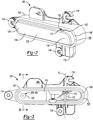
FIG. 2 is a front perspective view of the door handle assembly ofFIG. 1 removed from the vehicle body; -
FIG. 3 is a front plan view of the door handle assembly ofFIG. 1 with a handle of the door handle assembly removed for visual clarity; -
FIG. 4 is a front exploded detailed view of a first compression mechanism of the door handle assembly ofFIG. 1 ; -
FIG. 5 is a rear perspective detailed view of a housing and the first compression mechanism of the door handle assembly ofFIG. 1 ; -
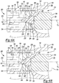
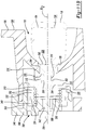
FIG. 6A is a cross-sectional view of the housing and the first compression mechanism of the door handle assembly ofFIG. 1 taken through the line 6-6 ofFIG. 3 , the first compression mechanism being in a first position; -
FIG. 6B is a cross-sectional view of the housing and the first compression mechanism of the door handle assembly ofFIG. 1 taken through the line 6-6 ofFIG. 3 , the first compression mechanism being in a second position; -
FIG. 7 is a front exploded detailed view of a second compression mechanism of the door handle assembly ofFIG. 1 ; -
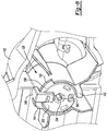
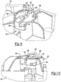
FIGS. 8-10 are rear perspective detailed views of the housing and the second compression mechanism of the door handle assembly ofFIG. 1 ; -
FIG. 11A is a cross-section view of the housing and the second compression mechanism of the door handle assembly ofFIG. 1 taken through the line 6-6 ofFIG. 3 , the second compression mechanism being in a first position; -
FIG. 11B is a cross-section view of the housing and the second compression mechanism of the door handle assembly ofFIG. 1 taken through the line 6-6 ofFIG. 3 , the second compression mechanism being in a second position; and -
FIG. 12 is a flowchart illustrating a method for operating the door handle assembly ofFIG. 1 . - Corresponding reference numerals indicate corresponding parts throughout the drawings.
- Example configurations will now be described more fully with reference to the accompanying drawings. Example configurations are provided so that this disclosure will be thorough, and will fully convey the scope of the disclosure to those of ordinary skill in the art. Specific details are set forth such as examples of specific components, devices, and methods, to provide a thorough understanding of configurations of the present disclosure. It will be apparent to those of ordinary skill in the art that specific details need not be employed, that example configurations may be embodied in many different forms, and that the specific details and the example configurations should not be construed to limit the scope of the disclosure.
- Referring to
FIG. 1 , adoor handle assembly 100 is generally shown. Thedoor handle assembly 100 may be installed in or attached to a vehicle, such as adoor panel 10 of a vehicle body of the vehicle. In other implementations, thedoor handle assembly 100 may be installed in a trunk door, a hood, or any other suitable location on a vehicle. Thedoor handle assembly 100 may facilitate opening of the door of the vehicle, and, as set forth in more detail below, thedoor handle assembly 100 may include certain features and functionality to allow auser 12 to break ice that has frozen over thedoor handle assembly 100. - Referring to
FIGS. 1 and2 , thedoor handle assembly 100 includes ahousing 102 and ahandle 104. Thehousing 102 includes anouter rim 106 defining anouter surface 108 and arecess 110 configured to receive thehandle 104. Theouter surface 108 may abut a portion of thedoor panel 10, e.g., an inner surface of thedoor panel 10. Thehousing 102 may include arod 112 disposed within therecess 110 and a biasingmember 114 engaged with or wrapped around therod 112. Therod 112 may define a first axis A1. Thehousing 102 includes at least one mountingfeature 116 to mount thehousing 102 to thedoor panel 10. - With continued reference to
FIGS. 1 and2 , thehandle 104 extends from aproximal end 118 to adistal end 120. Thehandle 104 may include anaperture 122 configured to receive therod 112 of thehousing 102. Thehandle 104 may rotate about the first axis A1 defined by therod 112 between a resting position (FIGS. 2 ,6A , and11A ), an extended position (FIG. 1 ), and a depressed position (FIGS. 6B and11B ). In some implementations, theaperture 122 may be disposed closer to theproximal end 118 than thedistal end 120, such that thehandle 104 rotates about the first axis A1 at a location closer to theproximal end 118 than thedistal end 120. In some implementations, thehandle 104 may be rotated between the resting position, the extended position, and the depressed position in response to a force exerted by theuser 12, e.g., by theuser 12 pressing against thehandle 104 at or near theproximal end 118 or at or near thedistal end 120. In other implementations, thehandle 104 may be rotated between these positions in response to a mechanical force, electrical force, and/or electro-mechanical force exerted by a system of the vehicle, i.e., thehandle 104 may be rotated without any direct contact between theuser 12 and thehandle 104. In yet other implementations, thehandle 104 may be rotated between these positions via a force exerted by a system of the vehicle (e.g., mechanical force, electrical force, and/or electro-mechanical force) in combination with a force exerted by the user 12 (e.g., by theuser 12 pressing against the handle 104), e.g., thehandle 104 may be rotated from the resting position to the depressed position by theuser 12 and from the resting position to the extended position by a force exerted by a system of the vehicle. The biasingmember 114 may bias thehandle 104 toward the resting position. In some implementations, the biasingmember 114 may also be configured to retain thehandle 104 in the extended position, or any other suitable mechanism may retain thehandle 104 in the extended position. - The
handle 104 may include anouter surface 124 that is substantially parallel to theouter surface 108 of theouter rim 106 of thehousing 102 when thehandle 104 is in the resting position. Thehandle 104 may include aninner surface 126 opposite theouter surface 124. Theinner surface 126 may face therecess 110 defined by theouter rim 106. As shown in the figures, thehandle 104 may include a generally rectangular shape with rounded corners; however, it should be understood that other shapes are contemplated, including rectangular, elliptical, L-shaped, circular, or any other suitable shape. - Referring to
FIGS. 3-6B , thedoor handle assembly 100 may include afirst compression mechanism 200. Thefirst compression mechanism 200 is configured to allow rotation of thehandle 104 between the resting position and the depressed position. Thehousing 102 includes abracket 128 defining anaperture 130 near a portion of therecess 110 that receives thedistal end 120 of thehandle 104, and at least a portion of thefirst compression mechanism 200 is disposed within theaperture 130. - The
first compression mechanism 200 includes aplunger 202, adamper 204, and a biasingmember 206. In some implementations, as shown inFIG. 5 , thebracket 128 may include at least oneslot 132 defining alip 134. Theplunger 202 may include abody 208 and a pair oflegs 210 extending from thebody 208. Thelegs 210 may each define acatch 212 that is configured to engage with thelip 134 such that theplunger 202 is coupled to thehousing 102. In other implementations, theplunger 202 may be coupled to thehandle 104, e.g., theinner surface 126 of thehandle 104. - The
body 208 of theplunger 202 may include acontact surface 214 facing theinner surface 126 of thehandle 104 and aninner surface 216 opposite thecontact surface 214, as shown inFIGS. 6A and 6B . Theplunger 202 is translatable between a first position when thehandle 104 is in the resting position (FIG. 6A ) and a second position when thehandle 104 is in the depressed position (FIG. 6B ). In some implementations, theplunger 202 may be translatable to a third position that is further depressed than the second position, e.g., theplunger 202 may be configured to depress or compress further than thehandle 104 can operate via interaction with the user 12 (or other suitable source) directly with the plunger 202 (e.g., if thehandle 104 was removed). Thebody 208 may define acentral bore 218 having alip 220. Thecentral bore 218 may be configured to receive thedamper 204. - The
damper 204 includes abody 222 defining acontact surface 224 facing theinner surface 126 of thehandle 104 and aninner surface 226 opposite thecontact surface 224. In some implementation, thecontact surface 224 of thedamper 204 may be substantially flush with thecontact surface 214 of theplunger 202. In other implementations, thecontact surface 224 of thedamper 204 may be offset from thecontact surface 214 of theplunger 202. Theinner surface 226 of thebody 222 may be configured to engage thelip 220 in thecentral bore 218 of thebody 208 of theplunger 202. Thedamper 204 may include astem 228 extending from thebody 222, thestem 228 including alip 230 configured to engage theinner surface 216 of thebody 208 of theplunger 202, as shown inFIGS. 6A and 6B . The engagement of theinner surface 226 with thelip 220 and theinner surface 216 with thelip 230 may secure thedamper 204 to theplunger 202. Accordingly, as theplunger 202 moves between the first position and the second position, thedamper 204 may likewise move between the first position and the second position. - Referring to
FIGS. 6A and 6B , thebracket 128 may include acentral portion 136 and aflange 138 extending from thecentral portion 136 to engage aninner surface 140 defining theaperture 130. The biasingmember 206 is disposed in theaperture 130 and extends from aproximal end 232 to adistal end 234. Theproximal end 232 may engage theinner surface 216 of thebody 208 of theplunger 202, and the distal end may engage theflange 138. In some implementations, the biasingmember 206 may be disposed around thecentral portion 136 of thebracket 128, such that the biasingmember 206 is coupled to thehousing 102 and such that a central cavity of the biasingmember 206 receives theplunger 202 and thedamper 204. In other implementations, the biasingmember 206 may be coupled to thehandle 104, e.g., theinner surface 126 of thehandle 104. The biasingmember 206 may be compressible along a second axis A2 defined by theaperture 130 of thebracket 128. The second axis A2 is perpendicular to the first axis A1. The biasingmember 206 may be any suitable element, such as a spring, a compressive plastic, a compressive foam, etc. - Referring to
FIGS. 7-11B , in some implementations, thedoor handle assembly 100 may include asecond compression mechanism 300. Thesecond compression mechanism 300 is configured to allow rotation of thehandle 104 between the resting position and the depressed position. At least a portion of thesecond compression mechanism 300 is disposed within theaperture 130 of thebracket 128 of thehousing 102. - The
second compression mechanism 300 includes aplunger 302, adamper 304, aplunger housing 306, and a biasingmember 308. In some implementations, theplunger 302 may be coupled to thehousing 102. In other implementations, theplunger 302 may be coupled to thehandle 104, e.g., theinner surface 126 of thehandle 104. Theplunger 302 includes abody 310 including arim 312 extending from thebody 310. Therim 312 may extend through theaperture 130, and an outer diameter of therim 312 may be substantially equal to an inner diameter of theaperture 130. Therim 312 may include anouter surface 314 facing theinner surface 126 of thehandle 104, and therim 312 may define acentral bore 316 configured to receive thedamper 304. Thebody 310 includes a steppedouter surface 318 adjacent therim 312 and an inner surface 320 opposite the steppedouter surface 318. The steppedouter surface 318 may engage a portion of thebracket 128, and the inner surface 320 may engage the biasingmember 308. - The
plunger 302 includes aradial flange 322 extending from thebody 310, and the radial flange may define acatch 324 that is configured to engage a portion of theplunger housing 306. Theplunger 302 is translatable between a first position when thehandle 104 is in the resting position (FIG. 11A ) and a second position when thehandle 104 is in the depressed position (FIG. 11B ). Therim 312 may include afirst portion 352 having a first inner diameter and asecond portion 354 having a second inner diameter greater than the first inner diameter. Thefirst portion 352 may be configured to engage a portion of thedamper 204. - The
damper 304 includes abody 326 defining acontact surface 328 facing theinner surface 126 of thehandle 104 and aninner surface 330 opposite thecontact surface 328. In some implementation, thecontact surface 224 of thedamper 204 may include a plurality of protrusions orridges 332 configured to engage with theinner surface 126 of thehandle 104. Theinner surface 330 of thebody 326 may be configured to engage theouter surface 314 of therim 312. Thedamper 304 may include astem 334 extending from thebody 326, thestem 334 including alip 336 configured to engage thefirst portion 352 of therim 312, as shown inFIGS. 11A and11B . The engagement of theinner surface 330 with theouter surface 314 and thelip 336 with thefirst portion 352 may secure thedamper 304 to theplunger 302. Accordingly, as theplunger 302 moves between the first position and the second position, thedamper 304 may likewise move between the first position and the second position. - Referring to
FIG. 7 , theplunger housing 306 may include abody 338 defining acavity 340 and acentral bore 342. Thecavity 340 may be configured to receive theplunger 302 and the biasingmember 308. Thecentral bore 342 may be configured to receive thestem 334 of thedamper 304. In some implementations, as shown inFIGS. 8-10 , thebracket 128 may include afirst engagement member 142 and asecond engagement member 144, and theplunger housing 306 may include athird engagement member 344 configured to engage thefirst engagement member 142 and afourth engagement member 346 configured to engage thesecond engagement member 144. Theengagement members first engagement member 142 may be a stepped protrusion defining a slot or recess and thethird engagement member 344 may be a protrusion that is configured to engage the slot. In some implementations, thesecond engagement member 144 may be a protrusion and thefourth engagement member 344 may be a stepped protrusion defining a slot or recess that is configured to receive the protrusion of thesecond engagement member 144. The engagement of theengagement members plunger housing 306 to thehousing 102. - Referring to
FIGS. 11A and11B , the biasingmember 308 is disposed in thecavity 340 in theaperture 130 and extends from aproximal end 348 to adistal end 350. Theproximal end 348 may engage the inner surface 320 of thebody 310 of theplunger 302, and the distal end may engage theplunger housing 306. In some implementations, the biasingmember 308 may be disposed around a portion of theplunger housing 306 that is secured to thehousing 102, such that the biasingmember 308 is likewise secured to thehousing 102 and such that a central cavity of the biasingmember 308 receives theplunger 302 and thedamper 304. In other implementations, the biasingmember 308 may be coupled to thehandle 104, e.g., theinner surface 126 of thehandle 104. The biasingmember 308 may be disposed around therim 312 of theplunger 302. The biasingmember 308 may be compressible along the second axis A2 defined by theaperture 130 of thebracket 128. The biasingmember 308 may be any suitable element, such as a spring, a compressive plastic, a compressive foam, etc. - Referring to
FIG. 12 , amethod 400 for operating thedoor handle assembly 100 is generally shown. Absent any force, thehandle 104 is disposed in the resting position (FIGS. 6A and11A ), e.g., by the biasingmember 114. At 402, theuser 12 may exert a first force at or near thedistal end 120 of thehandle 104 to move thedistal end 120 toward the vehicle. In other implementations, at 402, a system of the vehicle may exert the first force (e.g., mechanical force, electrical force, and/or electro-mechanical force) upon thehandle 104 to move thedistal end 120 toward the vehicle. At this point, thehandle 104 may be in the depressed position (FIGS. 6B and11B ) and may urge theplunger damper member distal end 120 of thehandle 104 to allow thehandle 104 to return to the resting position (FIGS. 6A and11A ). At 406, as shown inFIG. 1 , theuser 12 may exert a second force at or near theproximal end 118 of thehandle 104 to move thehandle 104 toward the extended position where thehandle 104 is spaced from thecompression mechanisms handle 104 to move thehandle 104 toward the extended position. At 408, theuser 12 may grasp and pull thehandle 104 to open the door of the vehicle. It should be understood that additional and/or different steps are contemplated, and the order of the steps may vary as suitable. - The terminology used herein is for the purpose of describing particular exemplary configurations only and is not intended to be limiting. As used herein, the singular articles "a," "an," and "the" may be intended to include the plural forms as well, unless the context clearly indicates otherwise. The terms "comprises," "comprising," "including," and "having," are inclusive and therefore specify the presence of features, steps, operations, elements, and/or components, but do not preclude the presence or addition of one or more other features, steps, operations, elements, components, and/or groups thereof. The method steps, processes, and operations described herein are not to be construed as necessarily requiring their performance in the particular order discussed or illustrated, unless specifically identified as an order of performance. Additional or alternative steps may be employed.
- When an element or layer is referred to as being "on," "engaged to," "connected to," "attached to," or "coupled to" another element or layer, it may be directly on, engaged, connected, attached, or coupled to the other element or layer, or intervening elements or layers may be present. In contrast, when an element is referred to as being "directly on," "directly engaged to," "directly connected to," "directly attached to," or "directly coupled to" another element or layer, there may be no intervening elements or layers present. Other words used to describe the relationship between elements should be interpreted in a like fashion (e.g., "between" versus "directly between," "adjacent" versus "directly adjacent," etc.). As used herein, the term "and/or" includes any and all combinations of one or more of the associated listed items.
- The terms first, second, third, etc. may be used herein to describe various elements, components, regions, layers and/or sections. These elements, components, regions, layers and/or sections should not be limited by these terms. These terms may be only used to distinguish one element, component, region, layer or section from another region, layer or section. Terms such as "first," "second," and other numerical terms do not imply a sequence or order unless clearly indicated by the context. Thus, a first element, component, region, layer or section discussed above could be termed a second element, component, region, layer or section without departing from the teachings of the example configurations.
- The foregoing description has been provided for purposes of illustration and description. It is not intended to be exhaustive or to limit the disclosure. Individual elements or features of a particular configuration are generally not limited to that particular configuration, but, where applicable, are interchangeable and can be used in a selected configuration, even if not specifically shown or described. The same may also be varied in many ways. Such variations are not to be regarded as a departure from the disclosure, and all such modifications are intended to be included within the scope of the disclosure.
- There follows a list of numbered features defining particular embodiments of the invention. Where a numbered feature refers to one or more earlier numbered features then those features may be considered in combination.
- 1. A door handle assembly for a vehicle, the door handle assembly comprising:
- a housing;
- a handle rotatably attached to the housing and rotatable between a resting position and a depressed position; and
- a compression mechanism configured to allow rotation of the handle between the resting position and the depressed position, the compression mechanism comprising:
- a plunger coupled to one of the housing or the handle and translatable between a first position when the handle is in the resting position and a second position when the handle is in the depressed position; and
- a biasing member coupled to one of the housing or the handle and configured to bias the plunger between the first position and the second position.
- 2. The door handle assembly of feature 1, wherein the handle extends from a proximal end to a distal end, and the handle is rotatably attached to the housing at a location closer to the proximal end than the distal end.
- 3. The door handle assembly of feature 2, wherein, when the handle is in the depressed position, the handle at or near the distal end urges the plunger to the second position and the biasing member to a compressed position.
- 4. The door handle assembly of features 2 or 3, wherein the handle is configured to rotate from the resting position to the depressed position by a user exerting a force upon the handle at or near the distal end.
- 5. The door handle assembly of any of features 2 to 4, wherein the handle is configured to rotate to an extended position where the handle is spaced from the plunger by a user exerting a force upon the handle at or near the proximal end.
- 6. The door handle assembly of any of the preceding features, wherein, when the handle is in the resting position, an outer surface of the handle is substantially parallel to an outer surface of the housing.
- 7. The door handle assembly of any of the preceding features, wherein the compression mechanism further includes a damper secured to the plunger and configured to engage the handle.
- 8. The door handle assembly of feature 7, wherein the plunger includes a central bore, and the damper is disposed in the central bore.
- 9. The door handle assembly of any of the preceding features, wherein the compression mechanism further includes a plunger housing coupled to the housing and configured to receive the plunger and the biasing member.
- 10. The door handle assembly of feature 9, wherein the plunger housing includes at least one tab and the housing includes at least one slot configured to receive the at least one tab to secure the plunger housing to the housing.
- 11. The door handle assembly of any of the preceding features, wherein the handle is rotatable about a first axis and the biasing member is compressible along a second axis perpendicular to the first axis.
- 12. A compression mechanism for allowing rotation of a handle between a resting position and a depressed position, the compression mechanism comprising:
- a plunger adjacent the handle and translatable between a first position when the handle is in the resting position and a second position when the handle is in the depressed position; and
- a biasing member adjacent the plunger and compressible between a third position when the handle is in the resting position and a fourth position when the handle is in the depressed position.
- 13. The compression mechanism of
feature 12, further comprising a damper secured to the plunger and engaged with the handle. - 14. The compression mechanism of feature 13, wherein the plunger includes a central bore, and the damper is disposed in the central bore.
- 15. The compression mechanism of features 13 or 14, wherein the biasing member defines a central cavity, the damper and the plunger extending into the central cavity.
- 16. The compression mechanism of any of
features 12 to 15, further comprising a plunger housing configured to receive the plunger and the biasing member. - 17. The compression mechanism of any of
features 12 to 16, wherein the biasing member compresses from the third position to the fourth position by the plunger exerting a force upon the biasing member. - 18. A method for operating a door handle assembly for a vehicle, the method comprising:
- exerting a first force upon a distal end of a handle to move the distal end toward the vehicle; and
- removing the first force upon the distal end of the handle to allow the handle to return to a resting position.
- 19. The method of feature 18, further comprising exerting a second force upon a proximal end of the handle to move the handle toward an extended position.
- 20. The method of feature 18 or 19, further comprising applying a second force upon the distal end while moving the distal end toward the vehicle, the second force being opposite the first force.
Claims (15)
- A door handle assembly for a vehicle, the door handle assembly comprising:a housing;a handle rotatably attached to the housing and rotatable between a resting position and a depressed position; anda compression mechanism configured to allow rotation of the handle between the resting position and the depressed position, the compression mechanism comprising:a plunger coupled to one of the housing or the handle and translatable between a first position when the handle is in the resting position and a second position when the handle is in the depressed position; anda biasing member coupled to one of the housing or the handle and configured to bias the plunger between the first position and the second position.
- The door handle assembly of claim 1, wherein the handle extends from a proximal end to a distal end, and the handle is rotatably attached to the housing at a location closer to the proximal end than the distal end; wherein, optionally, when the handle is in the depressed position, the handle at or near the distal end urges the plunger to the second position and the biasing member to a compressed position.
- The door handle assembly of claim 2, wherein the handle is configured to rotate from the resting position to the depressed position by a user exerting a force upon the handle at or near the distal end.
- The door handle assembly of any of claims 2 to 3, wherein the handle is configured to rotate to an extended position where the handle is spaced from the plunger by a user exerting a force upon the handle at or near the proximal end.
- The door handle assembly of any of the preceding claims, wherein, when the handle is in the resting position, an outer surface of the handle is substantially parallel to an outer surface of the housing.
- The door handle assembly of any of the preceding claims, wherein the compression mechanism further includes a damper secured to the plunger and configured to engage the handle; wherein optionally the plunger includes a central bore, and the damper is disposed in the central bore.
- The door handle assembly of any of the preceding claims, wherein the compression mechanism further includes a plunger housing coupled to the housing and configured to receive the plunger and the biasing member; wherein optionally the plunger housing includes at least one tab and the housing includes at least one slot configured to receive the at least one tab to secure the plunger housing to the housing.
- The door handle assembly of any of the preceding claims, wherein the handle is rotatable about a first axis and the biasing member is compressible along a second axis perpendicular to the first axis.
- A compression mechanism for allowing rotation of a handle between a resting position and a depressed position, the compression mechanism comprising:a plunger adjacent the handle and translatable between a first position when the handle is in the resting position and a second position when the handle is in the depressed position; anda biasing member adjacent the plunger and compressible between a third position when the handle is in the resting position and a fourth position when the handle is in the depressed position.
- The compression mechanism of claim 9, further comprising a damper secured to the plunger and engaged with the handle; wherein optionally the plunger includes a central bore, and the damper is disposed in the central bore.
- The compression mechanism of claim 10, wherein the biasing member defines a central cavity, the damper and the plunger extending into the central cavity.
- The compression mechanism of any of claims 9 to 11, further comprising a plunger housing configured to receive the plunger and the biasing member.
- The compression mechanism of any of claims 9 to 12, wherein the biasing member compresses from the third position to the fourth position by the plunger exerting a force upon the biasing member.
- A method for operating a door handle assembly for a vehicle, the method comprising:exerting a first force upon a distal end of a handle to move the distal end toward the vehicle; andremoving the first force upon the distal end of the handle to allow the handle to return to a resting position.
- The method of claim 14, further comprising:i) exerting a second force upon a proximal end of the handle to move the handle toward an extended position; and/orii) applying a second force upon the distal end while moving the distal end toward the vehicle, the second force being opposite the first force.
Applications Claiming Priority (1)
| Application Number | Priority Date | Filing Date | Title |
|---|---|---|---|
| US15/931,907 US11578512B2 (en) | 2020-05-14 | 2020-05-14 | Vehicle door handle assembly |
Publications (1)
| Publication Number | Publication Date |
|---|---|
| EP3910137A1 true EP3910137A1 (en) | 2021-11-17 |
Family
ID=75914318
Family Applications (1)
| Application Number | Title | Priority Date | Filing Date |
|---|---|---|---|
| EP21173436.3A Pending EP3910137A1 (en) | 2020-05-14 | 2021-05-11 | Vehicle door handle assembly |
Country Status (3)
| Country | Link |
|---|---|
| US (1) | US11578512B2 (en) |
| EP (1) | EP3910137A1 (en) |
| CN (1) | CN113668963B (en) |
Families Citing this family (5)
| Publication number | Priority date | Publication date | Assignee | Title |
|---|---|---|---|---|
| DE102018010031B4 (en) * | 2018-12-19 | 2025-10-09 | Mercedes-Benz Group AG | Vehicle door with extendable door handle |
| US11814883B2 (en) * | 2021-03-16 | 2023-11-14 | GM Global Technology Operations LLC | Anti-theft pass-through pawl for an access door |
| DE102022212967A1 (en) * | 2022-12-01 | 2024-06-06 | Brose Fahrzeugteile Se & Co. Kommanditgesellschaft, Bamberg | Door handle unit for a vehicle door |
| US20250215731A1 (en) * | 2023-12-28 | 2025-07-03 | Sl Corporation | Door handle for vehicle |
| JP2025139253A (en) * | 2024-03-12 | 2025-09-26 | ミネベアアクセスソリューションズ株式会社 | Door handle device for vehicle |
Citations (5)
| Publication number | Priority date | Publication date | Assignee | Title |
|---|---|---|---|---|
| DE102010056437A1 (en) * | 2010-12-28 | 2012-06-28 | Magna Mirrors Holding Gmbh | Actuating device for a vehicle door |
| FR3047037A1 (en) * | 2016-01-26 | 2017-07-28 | Peugeot Citroen Automobiles Sa | FLUSH HANDLE WITH PUSH-PULL FUNCTION FOR OPENING MOTOR VEHICLE |
| US20180171686A1 (en) * | 2016-12-20 | 2018-06-21 | Mgi Coutier | Leveled opening control |
| FR3071861A1 (en) * | 2017-10-03 | 2019-04-05 | Psa Automobiles Sa | MECHANISM FOR MANEUVERING A "FLUSH" HANDLE OPENING A MOTOR VEHICLE, AGAINST ITS IMMOBILIZATION IN THE POSITION OF ESCAMOTAGE. |
| FR3087810A1 (en) * | 2018-10-31 | 2020-05-01 | Psa Automobiles Sa | MULTIPLE EFFORT OPENING OPENING ORDER |
Family Cites Families (19)
| Publication number | Priority date | Publication date | Assignee | Title |
|---|---|---|---|---|
| US2208818A (en) * | 1939-05-23 | 1940-07-23 | Schaffler Oscar | Receding door latch handle |
| US2649322A (en) * | 1946-05-20 | 1953-08-18 | Mack Grant | Flush door latching mechanism |
| US3508778A (en) * | 1968-11-21 | 1970-04-28 | Gen Motors Corp | Flush type door handle for vehicle bodies |
| US4580821A (en) * | 1984-08-06 | 1986-04-08 | General Motors Corporation | Vehicle body door handle assembly |
| DE50202760D1 (en) * | 2001-05-17 | 2005-05-19 | Julius Blum Gmbh Hoechst | Dampers, in particular for furniture |
| DE20120112U1 (en) * | 2001-12-12 | 2002-02-21 | Arturo Salice S.P.A., Novedrate, Como | Air damper for moving furniture parts |
| US7377500B2 (en) * | 2003-12-26 | 2008-05-27 | Nifco Inc. | Shock absorbing device for moving body |
| JP4536580B2 (en) * | 2004-05-13 | 2010-09-01 | 株式会社ニフコ | Automotive door handle equipment |
| DE102005040761A1 (en) * | 2005-08-26 | 2007-03-15 | Webasto Ag | Closing device e.g. rear flap, operating device for e.g. estate car, has swivelably supported sensor flap actuating two different closing functions of closing device by swiveling from normal position in two opposite directions |
| DE102009045843A1 (en) | 2009-10-20 | 2011-04-21 | Huf Hülsbeck & Fürst Gmbh & Co. Kg | handle device |
| DE102013112705A1 (en) * | 2013-11-18 | 2015-05-21 | Illinois Tool Works Inc. | System of a component and an actuating device for the component |
| US10081969B2 (en) * | 2014-04-16 | 2018-09-25 | Dynalloy, Inc. | Lockable latching device |
| FR3024173B1 (en) * | 2014-07-25 | 2016-07-29 | Mgi Coutier Espana Sl | HANDLE ASSEMBLY FOR A MOTOR VEHICLE AND OPENING COMPRISING SUCH A HANDLE ASSEMBLY |
| GB2536672B (en) * | 2015-03-25 | 2018-04-04 | Jaguar Land Rover Ltd | Rectractable handle arrangement with emergency manual deployment |
| CN106761062A (en) | 2016-12-01 | 2017-05-31 | 东莞市蓝光塑胶模具有限公司 | An automatic retractable door handle |
| DE102017101421A1 (en) | 2017-01-25 | 2018-07-26 | Daimler Ag | Door handle assembly for a vehicle door |
| DE102017101418B4 (en) | 2017-01-25 | 2025-05-28 | Huf Hülsbeck & Fürst Gmbh & Co. Kg | Door handle arrangement for a vehicle door |
| US10837197B2 (en) * | 2018-06-25 | 2020-11-17 | Christopher Kightlinger | Handle for door closing |
| FR3101577B1 (en) * | 2019-10-04 | 2021-09-17 | Psa Automobiles Sa | Method and preventive device in the event of frost, of a blocking of a gripping member of a "flush" handle fitted to an opening of a motor vehicle. |
-
2020
- 2020-05-14 US US15/931,907 patent/US11578512B2/en active Active
-
2021
- 2021-05-11 EP EP21173436.3A patent/EP3910137A1/en active Pending
- 2021-05-12 CN CN202110516041.6A patent/CN113668963B/en active Active
Patent Citations (5)
| Publication number | Priority date | Publication date | Assignee | Title |
|---|---|---|---|---|
| DE102010056437A1 (en) * | 2010-12-28 | 2012-06-28 | Magna Mirrors Holding Gmbh | Actuating device for a vehicle door |
| FR3047037A1 (en) * | 2016-01-26 | 2017-07-28 | Peugeot Citroen Automobiles Sa | FLUSH HANDLE WITH PUSH-PULL FUNCTION FOR OPENING MOTOR VEHICLE |
| US20180171686A1 (en) * | 2016-12-20 | 2018-06-21 | Mgi Coutier | Leveled opening control |
| FR3071861A1 (en) * | 2017-10-03 | 2019-04-05 | Psa Automobiles Sa | MECHANISM FOR MANEUVERING A "FLUSH" HANDLE OPENING A MOTOR VEHICLE, AGAINST ITS IMMOBILIZATION IN THE POSITION OF ESCAMOTAGE. |
| FR3087810A1 (en) * | 2018-10-31 | 2020-05-01 | Psa Automobiles Sa | MULTIPLE EFFORT OPENING OPENING ORDER |
Also Published As
| Publication number | Publication date |
|---|---|
| US11578512B2 (en) | 2023-02-14 |
| US20210355721A1 (en) | 2021-11-18 |
| CN113668963B (en) | 2023-05-26 |
| CN113668963A (en) | 2021-11-19 |
Similar Documents
| Publication | Publication Date | Title |
|---|---|---|
| US11578512B2 (en) | Vehicle door handle assembly | |
| US20180245380A1 (en) | Handle for a vehicle door | |
| CN102378845A (en) | Snap fastener | |
| US10246909B2 (en) | Electronic handle for a vehicle door | |
| EP1848872B1 (en) | Cylinder lock assembly | |
| CN110799065B (en) | Linear actuator | |
| US12305430B2 (en) | Door handle assembly and related methods | |
| EP1182090A3 (en) | Rotary connector with locking mechanism for preventing rotation of housing prior to installation onto steering device | |
| US20120193198A1 (en) | Switch device | |
| EP1207255A2 (en) | Mechanical module for a key, key provided with such a module and method of mounting such a module on a key | |
| TWI542772B (en) | Simple lock device and handle device with the same | |
| CA2398671C (en) | A push button release apparatus | |
| JPH03197782A (en) | Latch device | |
| US20080314096A1 (en) | Door Lock | |
| US5998746A (en) | Self-adjusting door-ajar switch | |
| CN103270567A (en) | Control device | |
| GB2272019A (en) | Easy assembly deadlocking door latch | |
| EP2407618A1 (en) | Snap-closing device for doors | |
| JPH04125951U (en) | Electronic component operating device | |
| EP1557853A1 (en) | Push button switch for vehicle | |
| US20050029820A1 (en) | Handle set including a spindle assembly configured to resist removal | |
| KR102601595B1 (en) | Door pop-up actuator unit of vehicle with door position detection | |
| CN108729745B (en) | Spare key of vehicle and remote control key for placing spare key | |
| JPS6324769Y2 (en) | ||
| WO2005066523A1 (en) | Braking device |
Legal Events
| Date | Code | Title | Description |
|---|---|---|---|
| PUAI | Public reference made under article 153(3) epc to a published international application that has entered the european phase |
Free format text: ORIGINAL CODE: 0009012 |
|
| STAA | Information on the status of an ep patent application or granted ep patent |
Free format text: STATUS: REQUEST FOR EXAMINATION WAS MADE |
|
| 17P | Request for examination filed |
Effective date: 20210511 |
|
| AK | Designated contracting states |
Kind code of ref document: A1 Designated state(s): AL AT BE BG CH CY CZ DE DK EE ES FI FR GB GR HR HU IE IS IT LI LT LU LV MC MK MT NL NO PL PT RO RS SE SI SK SM TR |
|
| B565 | Issuance of search results under rule 164(2) epc |
Effective date: 20211018 |
|
| P01 | Opt-out of the competence of the unified patent court (upc) registered |
Effective date: 20230505 |
|
| STAA | Information on the status of an ep patent application or granted ep patent |
Free format text: STATUS: EXAMINATION IS IN PROGRESS |
|
| 17Q | First examination report despatched |
Effective date: 20250904 |