EP3909939A1 - Oligomer manufacturing apparatus - Google Patents
Oligomer manufacturing apparatus Download PDFInfo
- Publication number
- EP3909939A1 EP3909939A1 EP20913873.4A EP20913873A EP3909939A1 EP 3909939 A1 EP3909939 A1 EP 3909939A1 EP 20913873 A EP20913873 A EP 20913873A EP 3909939 A1 EP3909939 A1 EP 3909939A1
- Authority
- EP
- European Patent Office
- Prior art keywords
- reactor
- solvent
- blade
- spray
- transfer line
- Prior art date
- Legal status (The legal status is an assumption and is not a legal conclusion. Google has not performed a legal analysis and makes no representation as to the accuracy of the status listed.)
- Granted
Links
Images
Classifications
-
- B—PERFORMING OPERATIONS; TRANSPORTING
- B01—PHYSICAL OR CHEMICAL PROCESSES OR APPARATUS IN GENERAL
- B01J—CHEMICAL OR PHYSICAL PROCESSES, e.g. CATALYSIS OR COLLOID CHEMISTRY; THEIR RELEVANT APPARATUS
- B01J8/00—Chemical or physical processes in general, conducted in the presence of fluids and solid particles; Apparatus for such processes
- B01J8/08—Chemical or physical processes in general, conducted in the presence of fluids and solid particles; Apparatus for such processes with moving particles
- B01J8/10—Chemical or physical processes in general, conducted in the presence of fluids and solid particles; Apparatus for such processes with moving particles moved by stirrers or by rotary drums or rotary receptacles or endless belts
-
- C—CHEMISTRY; METALLURGY
- C07—ORGANIC CHEMISTRY
- C07C—ACYCLIC OR CARBOCYCLIC COMPOUNDS
- C07C2/00—Preparation of hydrocarbons from hydrocarbons containing a smaller number of carbon atoms
- C07C2/02—Preparation of hydrocarbons from hydrocarbons containing a smaller number of carbon atoms by addition between unsaturated hydrocarbons
- C07C2/04—Preparation of hydrocarbons from hydrocarbons containing a smaller number of carbon atoms by addition between unsaturated hydrocarbons by oligomerisation of well-defined unsaturated hydrocarbons without ring formation
- C07C2/06—Preparation of hydrocarbons from hydrocarbons containing a smaller number of carbon atoms by addition between unsaturated hydrocarbons by oligomerisation of well-defined unsaturated hydrocarbons without ring formation of alkenes, i.e. acyclic hydrocarbons having only one carbon-to-carbon double bond
-
- B—PERFORMING OPERATIONS; TRANSPORTING
- B01—PHYSICAL OR CHEMICAL PROCESSES OR APPARATUS IN GENERAL
- B01J—CHEMICAL OR PHYSICAL PROCESSES, e.g. CATALYSIS OR COLLOID CHEMISTRY; THEIR RELEVANT APPARATUS
- B01J10/00—Chemical processes in general for reacting liquid with gaseous media other than in the presence of solid particles, or apparatus specially adapted therefor
- B01J10/002—Chemical processes in general for reacting liquid with gaseous media other than in the presence of solid particles, or apparatus specially adapted therefor carried out in foam, aerosol or bubbles
-
- B—PERFORMING OPERATIONS; TRANSPORTING
- B01—PHYSICAL OR CHEMICAL PROCESSES OR APPARATUS IN GENERAL
- B01J—CHEMICAL OR PHYSICAL PROCESSES, e.g. CATALYSIS OR COLLOID CHEMISTRY; THEIR RELEVANT APPARATUS
- B01J19/00—Chemical, physical or physico-chemical processes in general; Their relevant apparatus
- B01J19/0053—Details of the reactor
- B01J19/006—Baffles
-
- B—PERFORMING OPERATIONS; TRANSPORTING
- B01—PHYSICAL OR CHEMICAL PROCESSES OR APPARATUS IN GENERAL
- B01J—CHEMICAL OR PHYSICAL PROCESSES, e.g. CATALYSIS OR COLLOID CHEMISTRY; THEIR RELEVANT APPARATUS
- B01J19/00—Chemical, physical or physico-chemical processes in general; Their relevant apparatus
- B01J19/0053—Details of the reactor
- B01J19/0066—Stirrers
-
- B—PERFORMING OPERATIONS; TRANSPORTING
- B01—PHYSICAL OR CHEMICAL PROCESSES OR APPARATUS IN GENERAL
- B01J—CHEMICAL OR PHYSICAL PROCESSES, e.g. CATALYSIS OR COLLOID CHEMISTRY; THEIR RELEVANT APPARATUS
- B01J19/00—Chemical, physical or physico-chemical processes in general; Their relevant apparatus
- B01J19/18—Stationary reactors having moving elements inside
-
- B—PERFORMING OPERATIONS; TRANSPORTING
- B01—PHYSICAL OR CHEMICAL PROCESSES OR APPARATUS IN GENERAL
- B01J—CHEMICAL OR PHYSICAL PROCESSES, e.g. CATALYSIS OR COLLOID CHEMISTRY; THEIR RELEVANT APPARATUS
- B01J19/00—Chemical, physical or physico-chemical processes in general; Their relevant apparatus
- B01J19/26—Nozzle-type reactors, i.e. the distribution of the initial reactants within the reactor is effected by their introduction or injection through nozzles
-
- B—PERFORMING OPERATIONS; TRANSPORTING
- B01—PHYSICAL OR CHEMICAL PROCESSES OR APPARATUS IN GENERAL
- B01J—CHEMICAL OR PHYSICAL PROCESSES, e.g. CATALYSIS OR COLLOID CHEMISTRY; THEIR RELEVANT APPARATUS
- B01J4/00—Feed or outlet devices; Feed or outlet control devices
- B01J4/001—Feed or outlet devices as such, e.g. feeding tubes
- B01J4/002—Nozzle-type elements
-
- B—PERFORMING OPERATIONS; TRANSPORTING
- B01—PHYSICAL OR CHEMICAL PROCESSES OR APPARATUS IN GENERAL
- B01J—CHEMICAL OR PHYSICAL PROCESSES, e.g. CATALYSIS OR COLLOID CHEMISTRY; THEIR RELEVANT APPARATUS
- B01J4/00—Feed or outlet devices; Feed or outlet control devices
- B01J4/001—Feed or outlet devices as such, e.g. feeding tubes
- B01J4/004—Sparger-type elements
-
- B—PERFORMING OPERATIONS; TRANSPORTING
- B01—PHYSICAL OR CHEMICAL PROCESSES OR APPARATUS IN GENERAL
- B01J—CHEMICAL OR PHYSICAL PROCESSES, e.g. CATALYSIS OR COLLOID CHEMISTRY; THEIR RELEVANT APPARATUS
- B01J8/00—Chemical or physical processes in general, conducted in the presence of fluids and solid particles; Apparatus for such processes
- B01J8/08—Chemical or physical processes in general, conducted in the presence of fluids and solid particles; Apparatus for such processes with moving particles
- B01J8/085—Feeding reactive fluids
-
- C—CHEMISTRY; METALLURGY
- C07—ORGANIC CHEMISTRY
- C07C—ACYCLIC OR CARBOCYCLIC COMPOUNDS
- C07C11/00—Aliphatic unsaturated hydrocarbons
- C07C11/02—Alkenes
- C07C11/04—Ethene
-
- C—CHEMISTRY; METALLURGY
- C07—ORGANIC CHEMISTRY
- C07C—ACYCLIC OR CARBOCYCLIC COMPOUNDS
- C07C11/00—Aliphatic unsaturated hydrocarbons
- C07C11/02—Alkenes
- C07C11/107—Alkenes with six carbon atoms
-
- C—CHEMISTRY; METALLURGY
- C07—ORGANIC CHEMISTRY
- C07C—ACYCLIC OR CARBOCYCLIC COMPOUNDS
- C07C2/00—Preparation of hydrocarbons from hydrocarbons containing a smaller number of carbon atoms
- C07C2/02—Preparation of hydrocarbons from hydrocarbons containing a smaller number of carbon atoms by addition between unsaturated hydrocarbons
- C07C2/04—Preparation of hydrocarbons from hydrocarbons containing a smaller number of carbon atoms by addition between unsaturated hydrocarbons by oligomerisation of well-defined unsaturated hydrocarbons without ring formation
- C07C2/06—Preparation of hydrocarbons from hydrocarbons containing a smaller number of carbon atoms by addition between unsaturated hydrocarbons by oligomerisation of well-defined unsaturated hydrocarbons without ring formation of alkenes, i.e. acyclic hydrocarbons having only one carbon-to-carbon double bond
- C07C2/08—Catalytic processes
-
- C—CHEMISTRY; METALLURGY
- C07—ORGANIC CHEMISTRY
- C07C—ACYCLIC OR CARBOCYCLIC COMPOUNDS
- C07C7/00—Purification; Separation; Use of additives
- C07C7/005—Processes comprising at least two steps in series
-
- C—CHEMISTRY; METALLURGY
- C07—ORGANIC CHEMISTRY
- C07C—ACYCLIC OR CARBOCYCLIC COMPOUNDS
- C07C7/00—Purification; Separation; Use of additives
- C07C7/04—Purification; Separation; Use of additives by distillation
-
- B—PERFORMING OPERATIONS; TRANSPORTING
- B01—PHYSICAL OR CHEMICAL PROCESSES OR APPARATUS IN GENERAL
- B01J—CHEMICAL OR PHYSICAL PROCESSES, e.g. CATALYSIS OR COLLOID CHEMISTRY; THEIR RELEVANT APPARATUS
- B01J2219/00—Chemical, physical or physico-chemical processes in general; Their relevant apparatus
- B01J2219/00049—Controlling or regulating processes
- B01J2219/00245—Avoiding undesirable reactions or side-effects
- B01J2219/00247—Fouling of the reactor or the process equipment
-
- B—PERFORMING OPERATIONS; TRANSPORTING
- B01—PHYSICAL OR CHEMICAL PROCESSES OR APPARATUS IN GENERAL
- B01J—CHEMICAL OR PHYSICAL PROCESSES, e.g. CATALYSIS OR COLLOID CHEMISTRY; THEIR RELEVANT APPARATUS
- B01J2219/00—Chemical, physical or physico-chemical processes in general; Their relevant apparatus
- B01J2219/00761—Details of the reactor
- B01J2219/00763—Baffles
- B01J2219/00779—Baffles attached to the stirring means
-
- B—PERFORMING OPERATIONS; TRANSPORTING
- B01—PHYSICAL OR CHEMICAL PROCESSES OR APPARATUS IN GENERAL
- B01J—CHEMICAL OR PHYSICAL PROCESSES, e.g. CATALYSIS OR COLLOID CHEMISTRY; THEIR RELEVANT APPARATUS
- B01J2219/00—Chemical, physical or physico-chemical processes in general; Their relevant apparatus
- B01J2219/00781—Aspects relating to microreactors
- B01J2219/0099—Cleaning
Definitions
- the present invention relates to an apparatus for preparing an oligomer, and more particularly, to an apparatus for preparing an oligomer for improving the stabilization of an entire process by reducing the amount of entrained solids and liquids in a reactor during the production of the oligomer
- Alpha-olefin which is an important substance used for a comonomer, a detergent, a lubricant, a plasticizer, etc., has been commercially widely used, and among them, 1-hexene and 1-octene have been mainly used as a comonomer for adjusting density of polyethylene during the production of linear low density polyethylene (LLDPE).
- LLDPE linear low density polyethylene
- the alpha-olefin such as 1-hexene and 1-octene has been typically produced through an oligomerization reaction of ethylene.
- the ethylene oligomerization reaction is performed by an oligomerization reaction (trimerization reaction or tetramerization reaction) of ethylene using ethylene as a reactant in the presence of a catalyst, and the product produced through the above reaction produces not only a multi-component hydrocarbon mixture containing the desired 1-hexene and 1-octene, but also a small amount of by-products containing C20+ polymer materials during catalytic reaction.
- the present invention has been made in an effort to solve the problems described above, and an object of the present invention is to provide an apparatus for preparing an oligomer for improving the stabilization of an entire process by preventing entrainment of by-products containing C20+ polymer materials other than a desired product in the reactor.
- an apparatus for preparing an oligomer including: a reactor for oligomerizing a feed stream containing a fed monomer; a stirrer inserted into a hole formed in an upper portion of the reactor; and a solvent transfer line extending inward from a side of the reactor, wherein the stirrer includes a rotating shaft vertically extending downward from the upper portion of the reactor, and a blade having a conical shape whose vertex is positioned at a lower end of the rotating shaft and outer diameter increases from a bottom toward a top, and the solvent transfer line has a plurality of spray nozzles formed in a direction toward the blade.
- stabilization of an entire process may be improved by installing a stirrer having a conical blade formed in a reactor to reduce the amount of entrained non-vapors such as solids and liquids in the reactor.
- the apparatus for preparing an oligomer according to the present invention includes a solvent transfer line having a plurality of spray nozzles formed toward the conical blade and capable of spraying a solvent, which may remove contaminants accumulated on an outer surface of the blade.
- the apparatus for preparing an oligomer according to the present invention may effectively increase the cycle of shutting down the operation of the reactor by preventing fouling from occurring in the post-processing apparatuses of the reactor, and may save an energy cost by preventing an efficiency degradation due to fouling of the post-processing apparatuses.
- the term "stream” may refer to a flow of fluid in a process, and may also refer to fluid itself flowing in a moving line (pipe). Specifically, the “stream” may refer to both of fluid itself flowing in a pipe connecting respective apparatuses to each other and a flow of the fluid.
- the fluid may mean that any one or more of gas, liquid, and solid is included.
- C# in which "#” is a positive integer refers to all hydrocarbons having # carbon atoms.
- C10 refers to a hydrocarbon compound having 10 carbon atoms.
- C#+ refers to all hydrocarbon molecules having # or more carbon atoms.
- C10+ refers to a mixture of hydrocarbons having 10 or more carbon atoms.
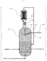
- an apparatus for preparing an oligomer includes: a reactor 100 for oligomerizing a feed stream containing a fed monomer; a stirrer 300 inserted into a hole formed in an upper portion of the reactor 100; and a solvent transfer line 400 extending inward from a side of the reactor 100, wherein the stirrer 300 includes a rotating shaft 310 vertically extending downward from the upper portion of the reactor 100, and a blade 320 having a conical shape whose vertex is positioned at a lower end of the rotating shaft 310 and outer diameter increases from a bottom toward a top, and the solvent transfer line 400 has a plurality of spray nozzles 411 formed in a direction toward the blade 320.
- the reactor 100 may produce an oligomer product by performing an oligomerization reaction of a monomer in the presence of a catalyst and a solvent.
- the reactor 100 may be a reactor 100 suitable for a continuous process.
- the reactor 100 may include one ore more reactors selected from the group consisting of a continuous stirred-tank reactor, a plug flow reactor, and a bubble column reactor. This allows the oligomer product to be produced continuously.
- the monomer may include ethylene.
- a feed stream containing an ethylene monomer may be fed to the reactor 100 and subjected to the oligomerization reaction to produce a desired alpha olefin product.
- the oligomerization reaction may be performed in a lower to middle region of the reactor 100, and the oligomerization reaction of the monomer may be performed in a liquid reaction medium dissolved in a solvent in the presence of a catalyst and a cocatalyst.
- the region made of the reaction medium in which the oligomerization reaction of a monomer is performed may be defined as a reaction region.
- the oligomerization reaction may refer to a reaction in which a monomer is oligomerized. Depending on the number of monomers to be polymerized, the oligomerization reaction is called trimerization and tetramerization, which are collectively called multimerization.
- the alpha-olefin which is an important substance used for a comonomer, a detergent, a lubricant, a plasticizer, etc., is commercially widely used, and among them, 1-hexene and 1-octene are mainly used as a comonomer for controlling a density of polyethylene during the production of linear low density polyethylene (LLDPE).
- the alpha-olefin such as 1-hexene and 1-octene may be produced, for example, through a trimerization reaction or a tetramerization reaction of the ethylene.
- the oligomerization reaction of the monomer may be performed as a homogeneous liquid-phase reaction using the reaction system and conventional contact techniques under the presence or absence of a solvent, a slurry reaction in which the catalyst is partially insoluble or entirely insoluble, a two-phase liquid/liquid reaction, or a bulk-phase or gas-phase reaction in which a product acts as a main medium.
- the solvent may fed into the position lower than the reaction region inside the reactor 100 through a lower side of the reactor 100.
- the solvent may include, for example, one or more selected from the group consisting of n-pentane, n-hexane, n-heptane, cyclohexane, methylcyclohexane, octane, cyclooctane, decane, dodecane, benzene, xylene, 1,3,5-trimethylbenzene, toluene, ethylbenzene, chlorobenzene, dichlorobenzene, and trichlorobenzene.
- the catalyst may include a transition metal source.
- the transition metal source may be, for example, a compound including one ore more selected from the group consisting of chromium(III) acetylacetonate, chromium(III) chloride tetrahydrofuran, chromium(III) 2-ethylhexanoate, chromium(III) tris (2,2,6,6-tetramethyl-3,5-heptanedionate), chromium(III) benzoylacetonate, chromium(III) hexafluoro-2,4-pentanedionate, chromium(III) acetate hydroxide, chromium(III) acetate, chromium(III) butyrate, chromium(III) pentanoate, chromium(III) laurate, and chromium(III) stearate.
- the cocatalyst may include, for example, one or more selected from the group consisting of trimethyl aluminium, triethyl aluminium, triisopropyl aluminium, triisobutyl aluminum, ethylaluminum sesquichloride, diethylaluminum chloride, ethyl aluminium dichloride, methylaluminoxane, modified methylaluminoxane, and borate.
- the feed stream containing the monomer may be fed into the reactor 100 through the lower portion of the reaction 100.
- the feed stream may be fed into the reactor 100 in a gaseous state.
- the gaseous feed stream fed into the reactor 100 passes through the liquid reaction medium in which a solvent and a catalyst exist, while the oligomerization reaction proceeds through the catalytic reaction, and in this case, gas and liquid are mixed as a reaction medium to exist in two phases.
- the oligomer product produced through the oligomerization reaction of the monomer may be discharged as a liquid second discharge stream, and an unreacted monomer not subjected to the oligomerization reaction in the reaction medium may be discharged as a gaseous first discharge stream.
- the first discharge stream of the reactor 100 may contain an unreacted monomer that did not participate in the oligomerization reaction of the monomer and a solvent.
- the first discharge stream containing the unreacted monomer and the solvent may be fed into a condenser 200.
- the first discharge stream condensed in a liquid phase in the condenser 200 is refluxed to the reaction region of the reactor and may be reused for the oligomerization reaction.
- the second discharge stream of the reactor 100 may include the oligomer product produced through the oligomerization reaction of the monomer, and a solvent.
- the oligomer product and the solvent may be separated through an additional separation apparatus (not illustrated), and the separated solvent may be reused in a process for preparing an oligomer.
- the oligomer product may include 1-hexene and 1-octene.
- a solid polymer is produced as by-products, in addition to a desired oligomer product, due to the catalytic reaction of the monomer, and is suspended in the liquid reaction medium.
- the solid polymer and a liquid solvent are entrained with a gaseous unreacted monomer at a speed at which the feed stream containing a large amount of gaseous monomers is introduced, and are discharged as the first discharge stream of the reactor 100.
- fouling occurs in the condenser 200, a pipe (not illustrated), and a valve (not illustrated), which are post-treatment apparatuses of the reactor 100, due to the adhesion of the polymer.
- the present invention may improve the stability of the entire process by installing a stirrer 300 having a conical blade 320 formed in the reactor 100 to prevent entrainment of by-products including polymer in addition to the desired oligomer product to prevent fouling in the post-processing apparatus.
- the apparatus for preparing an oligomer according to the present invention includes a solvent transfer line 400 having a plurality of spray nozzles 411 formed toward the conical blade 320 and capable of spraying a solvent, which may remove contaminants accumulated on an outer surface of the blade 320 in real time.
- the apparatus for preparing an oligomer according to the present invention may effectively increase the cycle of shutting down the operation of the reactor 100 by preventing fouling from occurring in the post-processing apparatus of the reactor 100, and may save an energy cost by preventing an efficiency degradation due to fouling of the post-processing apparatus.
- the apparatus for preparing an oligomer may include a stirrer 300 inserted into a hole formed in an upper portion of the reactor 100.
- the hole formed in the upper portion of the reactor 100 may be formed in the center of the reactor 100.
- the stirrer 300 may be inserted into and fixed in a hole formed in the upper portion of the reactor 100.
- Tee stirrer 300 may include a rotating shaft 310 vertically extending downward from the upper portion of the reactor, and a blade 320 having a conical shape whose vertex is positioned at a lower end of the rotating shaft 310 and outer diameter increases from the bottom toward the top.
- the rotating shaft 310 is a central shaft when the stirrer 300 rotates, and the stirrer 300 may rotate about the rotating shaft 310.
- the rotational motion of the rotating shaft 310 may cause the blade 320 formed at the lower end of the rotating shaft 310 to rotate.
- the rotating shaft 310 extends vertically downward from the upper portion of the reactor 100, and a length of the rotating shaft 310 may freely extend in a region between interfaces of the reaction medium in the upper portion of the reactor 100.
- the blade 320 is fixed to the lower end of the rotating shaft 310, has a conical shape whose vertex is positioned at the lower end of the rotating shaft 310 and outer diameter increases from the bottom toward the top, and may be formed entirely in a V-shape when viewed in the longitudinal section.
- the blade 320 rotates according to the rotational motion of the rotating shaft 310, the rotating shaft 310 is connected to a driving portion 330 such as a motor, and the driving portion 330 performs a function of rotating the rotating shaft 310.
- the gaseous stream may refer to, for example, a gaseous first discharge stream discharged from the reactor 100, and the gaseous first discharge stream contains non-vapor in a solid state such as a polymer and non-vapor in a liquid state such as a liquid drop in the process of moving to the upper portion of the reactor 100.
- the non-vapor entrained in the reactor 100 may be guided in the downward direction of the reactor 100 due to airflow formed by rotating the blades 320, and thus, the amount of the polymer entrained in the gaseous first discharge stream discharged to the upper portion of the reactor 100 may be significantly reduced.
- the occurrence of fouling may be prevented in the condenser 200 for condensing the first discharge stream, which is installed in the upper portion of the reaction 100, by reducing the amount of the polymer entrained in the first discharge stream, and thus heat exchange efficiency of the condenser 200 may be increased to save energy.
- the gaseous stream guided in the downward direction of the reactor 100 contains an unreacted monomer due to the rotation of the blade 320, and may increase a conversion rate into the oligomer by being circulated into a reaction medium and reused for the oligomerization reaction.
- the blade 320 may have a vertex angle of 45° to 150°, 60° to 130°, or 90° to 130°.
- the blade 320 may have a vertex angle within the above range to effectively remove non-vapor entrained in the first discharge stream. Specifically, the larger the vertex angle of the blade 320, the wider the range to prevent entrainment, and at the same time, the higher the possibility of fouling. Thus, it is important to properly adjust the vertex angle of the blade 320.
- the outer surface of the blade 320 may include an inclined portion 321 inclined at a predetermined angle from a vertex toward a top about the rotating shaft. Contaminants such as the polymer entrained in the rising first discharge stream may be attached to and accumulated on the inclined portion 321. As such, when the contaminants are accumulated on the inclined portion 321 of the blade 320, it may be immediately removed due to the plurality of spray nozzles 411 formed in the solvent transfer line 400 to be described later.
- the solvent transfer line 400 extending inward from the side of the reactor 100 may be included.
- the solvent transfer line 400 may be formed to extend from the side surface of the reactor 100 to a region spaced apart from the inner wall of the reaction 100.
- the solvent transfer line 400 may be installed to prevent the attachment and accumulation of the contaminants such as polymers on the blade 320.
- a plurality of spray nozzles 411 may be formed in the solvent transfer line 400 in a direction toward the blade 320.
- the solvent transfer line 400 may include a spray portion 410 in which the spray nozzle is formed, and a plurality of spray nozzles 411 may be formed in the spray portion 410.
- the plurality of spray nozzles 411 may be installed in a direction toward the blade 320 to spray a solvent toward the blade 320. Specifically, the solvent sprayed through the plurality of spray nozzles 411 may be sprayed toward the inclined portion 321 of the outer surface of the blade 320.
- the solvent transfer line 400 may be fixed to the reactor 100. Specifically, the solvent transfer line 400 may be inserted into and fixed in a hole formed on the side of the reactor 100.
- the shape of the solvent transfer line 400 is not particularly limited, and the material may be formed as a pipe used in the art as long as it is a material that is not corroded by a solvent.
- the spray portion 410 of the solvent transfer line 400 may have a slope corresponding to the inclined portion 321 of the outer surface of the blade 320, and may be disposed to be spaced apart from the inclined portion by a predetermined interval.
- the spray portion 410 in which the plurality of spray nozzles 411 are formed may be disposed to be spaced apart from the inclined portion 321 by a predetermined interval so as to have a slope, shape, and length corresponding to the inclined portion 321 of the outer surface of the blade 320.
- the spray portion 410 of the solvent transfer line 400 has a slope corresponding to the inclined portion 321 of the outer surface of the blade 320 and is disposed to be spaced apart from the inclined portion 321 by a predetermined interval, such that a solvent may be sprayed on the inclined portion 321 of the blade 320 through a plurality of spray nozzles 411 formed on the spray portion 410.
- the spray portion 410 of the solvent transfer line 400 is fixed to the reactor 100, the inclined portion 321 of the outer surface of the blade 320 is rotated due to the rotational motion of the rotation shaft 310 of the stirrer 300, and the spray portion 410 and the inclined portion 321 may be disposed to be spaced apart from each other by a predetermined interval in order to minimize friction in this process.
- the solvent may be sprayed toward the outer surface of the blade 320 through a plurality of spray nozzles 411 formed in the solvent transfer line 400 fixed to the reactor 100, and in this case, as the stirrer 300 rotates, the blade 320 rotates, and the contaminants accumulated on the outer surface of the blade 320 may be dissolved in a solvent sprayed through the spray nozzle 411 and removed therefrom.
- the solvent sprayed through the plurality of spray nozzles 411 may be the same as the solvent used for the oligomerization reaction of the feed stream containing monomers in the reactor 100.
- the solvent may include, for example, one or more selected from the group consisting of n-pentane, n-hexane, n-heptane, cyclohexane, methylcyclohexane, octane, cyclooctane, decane, dodecane, benzene, xylene, 1,3,5-trimethylbenzene, toluene, ethylbenzene, chlorobenzene, dichlorobenzene, and trichlorobenzene.
- the same solvent as the solvent used in the oligomerization reaction is used, such that the dissolving power for the polymer is excellent, and the inflow of external factors into the reactor 100 may be prevented, thereby improving stability.
- the temperature of the solvent sprayed through the plurality of spray nozzles 411 may be 100 to 300°C.
- the temperature of the solvent may be 130°C to 250°C, 150°C to 250°C, or 150°C to 200°C.
- spray nozzles 411 may be formed on the spray portion 410.
- the number of the spray nozzles may be easily changed depending on the diameter of the reactor 100 and the size of the blade 320 of the stirrer 300 changed accordingly.
- the plurality of spray nozzles 411 may include at least one spray port.
- the spray nozzle 411 may be implemented in the form of a spray including a plurality of spray ports.
- the spray nozzle 411 may have 1 to 5, 1 to 4, or 2 to 4 spray ports. Referring to FIG. 1 as an example, the spray nozzle 411 may be implemented with three spray ports.
- a plurality of spray nozzles 411 may be arranged in a line at predetermined intervals.
- the pressure of the solvent sprayed through the plurality of spray nozzles 411 may be 1 bar.g to 100 bar.g.
- the spray pressure of the solvent may be 3 bar.g to 80 bar.g, 5 bar.g to 75 bar.g, or 20 bar.g to 70 bar.g.
- the contaminants accumulated on the inclined portion 321 of the outer surface of the blade 320 may be effectively removed by spraying the solvent at a pressure within the above range.
- each of the spray nozzles 411 may have different pressures for spraying the solvent.
- the contaminants accumulated on the inclined portion 321 of the outer surface of the blade 320 may be removed more efficiently by varying the spray pressure of the plurality of spray nozzles 411 arranged to be spaced apart from the spray portion 410 in a line at predetermined intervals.
- the mixed vapor rises in a non-uniform state by the vortex in the region adjacent to the inner wall of the reactor 100, and the mixed vapor rises between the blade 320 and the inner wall of the reactor 100, and thus, in the outer surface of the blade 320, a large amount of contaminants may be accumulated on a region adjacent to the inner wall of the reactor 100, that is, a region far from the vertex of the blade 320.
- the apparatus for preparing the oligomer may further install apparatuses required to produce the oligomer, such as a valve, a condenser, a reboiler, a pump, a cooling facility, a filter, a stirrer, a separation apparatus, a compressor and a mixer, if necessary.
- apparatuses required to produce the oligomer such as a valve, a condenser, a reboiler, a pump, a cooling facility, a filter, a stirrer, a separation apparatus, a compressor and a mixer, if necessary.
Landscapes
- Chemical & Material Sciences (AREA)
- Organic Chemistry (AREA)
- Chemical Kinetics & Catalysis (AREA)
- Engineering & Computer Science (AREA)
- Analytical Chemistry (AREA)
- Oil, Petroleum & Natural Gas (AREA)
- Water Supply & Treatment (AREA)
- Dispersion Chemistry (AREA)
- Organic Low-Molecular-Weight Compounds And Preparation Thereof (AREA)
- Combustion & Propulsion (AREA)
- Polymerisation Methods In General (AREA)
Abstract
Description
- This application claims benefit of priority of
Korean Patent Application No. 10-2020-0004722 filed on January 14, 2020 - The present invention relates to an apparatus for preparing an oligomer, and more particularly, to an apparatus for preparing an oligomer for improving the stabilization of an entire process by reducing the amount of entrained solids and liquids in a reactor during the production of the oligomer
- Alpha-olefin, which is an important substance used for a comonomer, a detergent, a lubricant, a plasticizer, etc., has been commercially widely used, and among them, 1-hexene and 1-octene have been mainly used as a comonomer for adjusting density of polyethylene during the production of linear low density polyethylene (LLDPE).
- The alpha-olefin such as 1-hexene and 1-octene has been typically produced through an oligomerization reaction of ethylene. The ethylene oligomerization reaction is performed by an oligomerization reaction (trimerization reaction or tetramerization reaction) of ethylene using ethylene as a reactant in the presence of a catalyst, and the product produced through the above reaction produces not only a multi-component hydrocarbon mixture containing the desired 1-hexene and 1-octene, but also a small amount of by-products containing C20+ polymer materials during catalytic reaction. These by-products are accumulated not only in an inner wall of the reactor, but also in post-processing apparatuses such as a condenser, a pipe, and a valve, thereby causing fouling. As such, the fouling that occurs in the post-processing apparatuses of the reactor causes poor performance and mechanical damage in the apparatus, and in the worst case, the operation of an entire process should be shut down, resulting in a decrease in production due to a decrease in operating time and an increase in a cost incurred during a cleaning process.
- Thus, in order to solve the problems described above, a study is needed to reduce the amount of entrained solids and liquids containing a polymer in the reactor.
- The present invention has been made in an effort to solve the problems described above, and an object of the present invention is to provide an apparatus for preparing an oligomer for improving the stabilization of an entire process by preventing entrainment of by-products containing C20+ polymer materials other than a desired product in the reactor.
- In one aspect, there is provided an apparatus for preparing an oligomer, the apparatus including: a reactor for oligomerizing a feed stream containing a fed monomer; a stirrer inserted into a hole formed in an upper portion of the reactor; and a solvent transfer line extending inward from a side of the reactor, wherein the stirrer includes a rotating shaft vertically extending downward from the upper portion of the reactor, and a blade having a conical shape whose vertex is positioned at a lower end of the rotating shaft and outer diameter increases from a bottom toward a top, and the solvent transfer line has a plurality of spray nozzles formed in a direction toward the blade.
- According to an apparatus for preparing an oligomer of the prevent invention, stabilization of an entire process may be improved by installing a stirrer having a conical blade formed in a reactor to reduce the amount of entrained non-vapors such as solids and liquids in the reactor.
- In addition, the apparatus for preparing an oligomer according to the present invention includes a solvent transfer line having a plurality of spray nozzles formed toward the conical blade and capable of spraying a solvent, which may remove contaminants accumulated on an outer surface of the blade.
- In addition, the apparatus for preparing an oligomer according to the present invention may effectively increase the cycle of shutting down the operation of the reactor by preventing fouling from occurring in the post-processing apparatuses of the reactor, and may save an energy cost by preventing an efficiency degradation due to fouling of the post-processing apparatuses.
-
-
FIG. 1 is a process flow chart illustrating an apparatus for preparing an oligomer according to an exemplary embodiment of the present invention. -
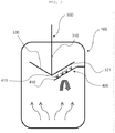
FIG. 2 is an enlarged view illustrating a part of the apparatus for preparing an oligomer according to an exemplary embodiment of the present invention. - The terms and words used in the detailed description and claims of the present invention should not be interpreted as being limited to conventional or dictionary meanings, but should be interpreted as having meanings and concepts meeting the technical ideas of the present invention based on a principle that the inventors can appropriately define the concepts of terms in order to describe their own inventions in the best mode.
- In the present invention, the term "stream" may refer to a flow of fluid in a process, and may also refer to fluid itself flowing in a moving line (pipe). Specifically, the "stream" may refer to both of fluid itself flowing in a pipe connecting respective apparatuses to each other and a flow of the fluid. In addition, the fluid may mean that any one or more of gas, liquid, and solid is included.
- In the present invention, the term "C#" in which "#" is a positive integer refers to all hydrocarbons having # carbon atoms. Thus, the term "C10" refers to a hydrocarbon compound having 10 carbon atoms. In addition, the term "C#+" refers to all hydrocarbon molecules having # or more carbon atoms. Thus, the term "C10+" refers to a mixture of hydrocarbons having 10 or more carbon atoms.
- Hereinafter, in order to help understand the present invention, the present invention will be described in more detail with reference to
FIGS. 1 and2 below. - According to the present invention, there is provided an apparatus for preparing an oligomer. The apparatus for preparing an oligomer includes: a
reactor 100 for oligomerizing a feed stream containing a fed monomer; astirrer 300 inserted into a hole formed in an upper portion of thereactor 100; and asolvent transfer line 400 extending inward from a side of thereactor 100, wherein thestirrer 300 includes arotating shaft 310 vertically extending downward from the upper portion of thereactor 100, and ablade 320 having a conical shape whose vertex is positioned at a lower end of the rotatingshaft 310 and outer diameter increases from a bottom toward a top, and thesolvent transfer line 400 has a plurality ofspray nozzles 411 formed in a direction toward theblade 320. - According to an exemplary embodiment of the present invention, the
reactor 100 may produce an oligomer product by performing an oligomerization reaction of a monomer in the presence of a catalyst and a solvent. - According to an exemplary embodiment of the present invention, the
reactor 100 may be areactor 100 suitable for a continuous process. For example, thereactor 100 may include one ore more reactors selected from the group consisting of a continuous stirred-tank reactor, a plug flow reactor, and a bubble column reactor. This allows the oligomer product to be produced continuously. - According to an exemplary embodiment of the present invention, the monomer may include ethylene. Specifically, a feed stream containing an ethylene monomer may be fed to the
reactor 100 and subjected to the oligomerization reaction to produce a desired alpha olefin product. In this case, the oligomerization reaction may be performed in a lower to middle region of thereactor 100, and the oligomerization reaction of the monomer may be performed in a liquid reaction medium dissolved in a solvent in the presence of a catalyst and a cocatalyst. As such, the region made of the reaction medium in which the oligomerization reaction of a monomer is performed may be defined as a reaction region. The oligomerization reaction may refer to a reaction in which a monomer is oligomerized. Depending on the number of monomers to be polymerized, the oligomerization reaction is called trimerization and tetramerization, which are collectively called multimerization. - The alpha-olefin, which is an important substance used for a comonomer, a detergent, a lubricant, a plasticizer, etc., is commercially widely used, and among them, 1-hexene and 1-octene are mainly used as a comonomer for controlling a density of polyethylene during the production of linear low density polyethylene (LLDPE). The alpha-olefin such as 1-hexene and 1-octene may be produced, for example, through a trimerization reaction or a tetramerization reaction of the ethylene.
- According to an exemplary embodiment of the present invention, the oligomerization reaction of the monomer may be performed as a homogeneous liquid-phase reaction using the reaction system and conventional contact techniques under the presence or absence of a solvent, a slurry reaction in which the catalyst is partially insoluble or entirely insoluble, a two-phase liquid/liquid reaction, or a bulk-phase or gas-phase reaction in which a product acts as a main medium.
- The solvent may fed into the position lower than the reaction region inside the
reactor 100 through a lower side of thereactor 100. The solvent may include, for example, one or more selected from the group consisting of n-pentane, n-hexane, n-heptane, cyclohexane, methylcyclohexane, octane, cyclooctane, decane, dodecane, benzene, xylene, 1,3,5-trimethylbenzene, toluene, ethylbenzene, chlorobenzene, dichlorobenzene, and trichlorobenzene. - The catalyst may include a transition metal source. The transition metal source may be, for example, a compound including one ore more selected from the group consisting of chromium(III) acetylacetonate, chromium(III) chloride tetrahydrofuran, chromium(III) 2-ethylhexanoate, chromium(III) tris (2,2,6,6-tetramethyl-3,5-heptanedionate), chromium(III) benzoylacetonate, chromium(III) hexafluoro-2,4-pentanedionate, chromium(III) acetate hydroxide, chromium(III) acetate, chromium(III) butyrate, chromium(III) pentanoate, chromium(III) laurate, and chromium(III) stearate.
- The cocatalyst may include, for example, one or more selected from the group consisting of trimethyl aluminium, triethyl aluminium, triisopropyl aluminium, triisobutyl aluminum, ethylaluminum sesquichloride, diethylaluminum chloride, ethyl aluminium dichloride, methylaluminoxane, modified methylaluminoxane, and borate.
- According to an exemplary embodiment of the present invention, the feed stream containing the monomer may be fed into the
reactor 100 through the lower portion of thereaction 100. In this case, the feed stream may be fed into thereactor 100 in a gaseous state. - The gaseous feed stream fed into the
reactor 100 passes through the liquid reaction medium in which a solvent and a catalyst exist, while the oligomerization reaction proceeds through the catalytic reaction, and in this case, gas and liquid are mixed as a reaction medium to exist in two phases. The oligomer product produced through the oligomerization reaction of the monomer may be discharged as a liquid second discharge stream, and an unreacted monomer not subjected to the oligomerization reaction in the reaction medium may be discharged as a gaseous first discharge stream. - Specifically, the first discharge stream of the
reactor 100 may contain an unreacted monomer that did not participate in the oligomerization reaction of the monomer and a solvent. As such, the first discharge stream containing the unreacted monomer and the solvent may be fed into acondenser 200. The first discharge stream condensed in a liquid phase in thecondenser 200 is refluxed to the reaction region of the reactor and may be reused for the oligomerization reaction. - In addition, the second discharge stream of the
reactor 100 may include the oligomer product produced through the oligomerization reaction of the monomer, and a solvent. In this case, the oligomer product and the solvent may be separated through an additional separation apparatus (not illustrated), and the separated solvent may be reused in a process for preparing an oligomer. In addition, for example, when the oligomerization reaction is performed using an ethylene monomer as the monomer, the oligomer product may include 1-hexene and 1-octene. - In the
reactor 100, a solid polymer is produced as by-products, in addition to a desired oligomer product, due to the catalytic reaction of the monomer, and is suspended in the liquid reaction medium. In this case, the solid polymer and a liquid solvent are entrained with a gaseous unreacted monomer at a speed at which the feed stream containing a large amount of gaseous monomers is introduced, and are discharged as the first discharge stream of thereactor 100. In this case, fouling occurs in thecondenser 200, a pipe (not illustrated), and a valve (not illustrated), which are post-treatment apparatuses of thereactor 100, due to the adhesion of the polymer. - On the other hand, the present invention may improve the stability of the entire process by installing a
stirrer 300 having aconical blade 320 formed in thereactor 100 to prevent entrainment of by-products including polymer in addition to the desired oligomer product to prevent fouling in the post-processing apparatus. - In addition, the apparatus for preparing an oligomer according to the present invention includes a
solvent transfer line 400 having a plurality ofspray nozzles 411 formed toward theconical blade 320 and capable of spraying a solvent, which may remove contaminants accumulated on an outer surface of theblade 320 in real time. - Further, the apparatus for preparing an oligomer according to the present invention may effectively increase the cycle of shutting down the operation of the
reactor 100 by preventing fouling from occurring in the post-processing apparatus of thereactor 100, and may save an energy cost by preventing an efficiency degradation due to fouling of the post-processing apparatus. - According to an exemplary embodiment of the present invention, the apparatus for preparing an oligomer may include a
stirrer 300 inserted into a hole formed in an upper portion of thereactor 100. For example, the hole formed in the upper portion of thereactor 100 may be formed in the center of thereactor 100. In addition, thestirrer 300 may be inserted into and fixed in a hole formed in the upper portion of thereactor 100. -
Tee stirrer 300 may include arotating shaft 310 vertically extending downward from the upper portion of the reactor, and ablade 320 having a conical shape whose vertex is positioned at a lower end of therotating shaft 310 and outer diameter increases from the bottom toward the top. - The
rotating shaft 310 is a central shaft when thestirrer 300 rotates, and thestirrer 300 may rotate about therotating shaft 310. In addition, the rotational motion of therotating shaft 310 may cause theblade 320 formed at the lower end of therotating shaft 310 to rotate. - The
rotating shaft 310 extends vertically downward from the upper portion of thereactor 100, and a length of therotating shaft 310 may freely extend in a region between interfaces of the reaction medium in the upper portion of thereactor 100. - The
blade 320 is fixed to the lower end of therotating shaft 310, has a conical shape whose vertex is positioned at the lower end of therotating shaft 310 and outer diameter increases from the bottom toward the top, and may be formed entirely in a V-shape when viewed in the longitudinal section. - The
blade 320 rotates according to the rotational motion of therotating shaft 310, therotating shaft 310 is connected to a drivingportion 330 such as a motor, and the drivingportion 330 performs a function of rotating therotating shaft 310. - When the
blade 320 rotates, a part of a gaseous stream moving from the lower portion to the upper portion of thereactor 100 may be guided in a downward direction of thereactor 100 due to the rotation of theblade 320. - The gaseous stream may refer to, for example, a gaseous first discharge stream discharged from the
reactor 100, and the gaseous first discharge stream contains non-vapor in a solid state such as a polymer and non-vapor in a liquid state such as a liquid drop in the process of moving to the upper portion of thereactor 100. - As such, the non-vapor entrained in the
reactor 100 may be guided in the downward direction of thereactor 100 due to airflow formed by rotating theblades 320, and thus, the amount of the polymer entrained in the gaseous first discharge stream discharged to the upper portion of thereactor 100 may be significantly reduced. - In addition, the occurrence of fouling may be prevented in the
condenser 200 for condensing the first discharge stream, which is installed in the upper portion of thereaction 100, by reducing the amount of the polymer entrained in the first discharge stream, and thus heat exchange efficiency of thecondenser 200 may be increased to save energy. - In addition, the gaseous stream guided in the downward direction of the
reactor 100 contains an unreacted monomer due to the rotation of theblade 320, and may increase a conversion rate into the oligomer by being circulated into a reaction medium and reused for the oligomerization reaction. - The
blade 320 may have a vertex angle of 45° to 150°, 60° to 130°, or 90° to 130°. Theblade 320 may have a vertex angle within the above range to effectively remove non-vapor entrained in the first discharge stream. Specifically, the larger the vertex angle of theblade 320, the wider the range to prevent entrainment, and at the same time, the higher the possibility of fouling. Thus, it is important to properly adjust the vertex angle of theblade 320. - The outer surface of the
blade 320 may include aninclined portion 321 inclined at a predetermined angle from a vertex toward a top about the rotating shaft. Contaminants such as the polymer entrained in the rising first discharge stream may be attached to and accumulated on theinclined portion 321. As such, when the contaminants are accumulated on theinclined portion 321 of theblade 320, it may be immediately removed due to the plurality ofspray nozzles 411 formed in thesolvent transfer line 400 to be described later. - According to an exemplary embodiment of the present invention, the
solvent transfer line 400 extending inward from the side of thereactor 100 may be included. Specifically, thesolvent transfer line 400 may be formed to extend from the side surface of thereactor 100 to a region spaced apart from the inner wall of thereaction 100. - The
solvent transfer line 400 may be installed to prevent the attachment and accumulation of the contaminants such as polymers on theblade 320. - A plurality of
spray nozzles 411 may be formed in thesolvent transfer line 400 in a direction toward theblade 320. Specifically, thesolvent transfer line 400 may include aspray portion 410 in which the spray nozzle is formed, and a plurality ofspray nozzles 411 may be formed in thespray portion 410. - The plurality of
spray nozzles 411 may be installed in a direction toward theblade 320 to spray a solvent toward theblade 320. Specifically, the solvent sprayed through the plurality ofspray nozzles 411 may be sprayed toward theinclined portion 321 of the outer surface of theblade 320. - The
solvent transfer line 400 may be fixed to thereactor 100. Specifically, thesolvent transfer line 400 may be inserted into and fixed in a hole formed on the side of thereactor 100. In this case, the shape of thesolvent transfer line 400 is not particularly limited, and the material may be formed as a pipe used in the art as long as it is a material that is not corroded by a solvent. - The
spray portion 410 of thesolvent transfer line 400 may have a slope corresponding to theinclined portion 321 of the outer surface of theblade 320, and may be disposed to be spaced apart from the inclined portion by a predetermined interval. Specifically, in thesolvent transfer line 400, thespray portion 410 in which the plurality ofspray nozzles 411 are formed may be disposed to be spaced apart from theinclined portion 321 by a predetermined interval so as to have a slope, shape, and length corresponding to theinclined portion 321 of the outer surface of theblade 320. - As such, the
spray portion 410 of thesolvent transfer line 400 has a slope corresponding to theinclined portion 321 of the outer surface of theblade 320 and is disposed to be spaced apart from theinclined portion 321 by a predetermined interval, such that a solvent may be sprayed on theinclined portion 321 of theblade 320 through a plurality ofspray nozzles 411 formed on thespray portion 410. - The
spray portion 410 of thesolvent transfer line 400 is fixed to thereactor 100, theinclined portion 321 of the outer surface of theblade 320 is rotated due to the rotational motion of therotation shaft 310 of thestirrer 300, and thespray portion 410 and theinclined portion 321 may be disposed to be spaced apart from each other by a predetermined interval in order to minimize friction in this process. - In addition, the solvent may be sprayed toward the outer surface of the
blade 320 through a plurality ofspray nozzles 411 formed in thesolvent transfer line 400 fixed to thereactor 100, and in this case, as thestirrer 300 rotates, theblade 320 rotates, and the contaminants accumulated on the outer surface of theblade 320 may be dissolved in a solvent sprayed through thespray nozzle 411 and removed therefrom. - The solvent sprayed through the plurality of
spray nozzles 411 may be the same as the solvent used for the oligomerization reaction of the feed stream containing monomers in thereactor 100. The solvent may include, for example, one or more selected from the group consisting of n-pentane, n-hexane, n-heptane, cyclohexane, methylcyclohexane, octane, cyclooctane, decane, dodecane, benzene, xylene, 1,3,5-trimethylbenzene, toluene, ethylbenzene, chlorobenzene, dichlorobenzene, and trichlorobenzene. As such, the same solvent as the solvent used in the oligomerization reaction is used, such that the dissolving power for the polymer is excellent, and the inflow of external factors into thereactor 100 may be prevented, thereby improving stability. - The temperature of the solvent sprayed through the plurality of
spray nozzles 411 may be 100 to 300°C. For example, the temperature of the solvent may be 130°C to 250°C, 150°C to 250°C, or 150°C to 200°C. When a high-temperature solvent within the above range is sprayed onto theinclined portion 321 of the outer surface of theblade 320, the contaminants accumulated on theinclined portion 321 may be effectively removed. - 2 to 10, 3 to 8, or 3 to 6
spray nozzles 411 may be formed on thespray portion 410. The number of the spray nozzles may be easily changed depending on the diameter of thereactor 100 and the size of theblade 320 of thestirrer 300 changed accordingly. - The plurality of
spray nozzles 411 may include at least one spray port. In addition, thespray nozzle 411 may be implemented in the form of a spray including a plurality of spray ports. For example, thespray nozzle 411 may have 1 to 5, 1 to 4, or 2 to 4 spray ports. Referring toFIG. 1 as an example, thespray nozzle 411 may be implemented with three spray ports. - In the
spray portion 410, a plurality ofspray nozzles 411 may be arranged in a line at predetermined intervals. - In the
spray portion 410, the pressure of the solvent sprayed through the plurality ofspray nozzles 411 may be 1 bar.g to 100 bar.g. For example, the spray pressure of the solvent may be 3 bar.g to 80 bar.g, 5 bar.g to 75 bar.g, or 20 bar.g to 70 bar.g. The contaminants accumulated on theinclined portion 321 of the outer surface of theblade 320 may be effectively removed by spraying the solvent at a pressure within the above range. - In the
spray portion 410 in which the plurality ofspray nozzles 411 of thesolvent transfer line 400 are formed, each of thespray nozzles 411 may have different pressures for spraying the solvent. For example, the contaminants accumulated on theinclined portion 321 of the outer surface of theblade 320 may be removed more efficiently by varying the spray pressure of the plurality ofspray nozzles 411 arranged to be spaced apart from thespray portion 410 in a line at predetermined intervals. - In the plurality of
spray nozzles 411 formed on thesolvent transfer line 400, the closer to the inner wall of thereactor 100, the higher the spray pressure of the solvent may be. - Specifically, the mixed vapor (vapor + non-vapor) rises in a non-uniform state by the vortex in the region adjacent to the inner wall of the
reactor 100, and the mixed vapor rises between theblade 320 and the inner wall of thereactor 100, and thus, in the outer surface of theblade 320, a large amount of contaminants may be accumulated on a region adjacent to the inner wall of thereactor 100, that is, a region far from the vertex of theblade 320. - Accordingly, in the plurality of
spray nozzles 411, the closer to the inner wall of thereactor 100, that is, the further away from the vertex of theblade 320, the higher the spray pressure of the solvent is adjusted, such that the contaminants accumulated on the outer surface of theblade 320 may be efficiently removed. - According to an embodiment of the present invention, the apparatus for preparing the oligomer may further install apparatuses required to produce the oligomer, such as a valve, a condenser, a reboiler, a pump, a cooling facility, a filter, a stirrer, a separation apparatus, a compressor and a mixer, if necessary.
- The apparatus for preparing an oligomer according to the present invention has been described and has been shown in the drawings herein, but only essential configurations for understanding the present invention have been described and have been illustrated in the drawings, and processes and apparatuses that are not separately described and illustrated, in addition to processes and apparatus described above and illustrated in the drawings, may be appropriately applied and used in order to implement the apparatus for preparing an oligomer according to the present invention.
Claims (13)
- An apparatus for preparing an oligomer, the apparatus comprising:a reactor for oligomerizing a feed stream containing a fed monomer;a stirrer inserted into a hole formed in an upper portion of the reactor; anda solvent transfer line extending inward from a side of the reactor;wherein the stirrer includes a rotating shaft vertically extending downward from the upper portion of the reactor, and a blade having a conical shape whose vertex is positioned at a lower end of the rotating shaft and outer diameter increases from a bottom toward a top, andthe solvent transfer line has a plurality of spray nozzles formed in a direction toward the blade.
- The apparatus of claim 1, wherein a part of a gaseous stream moving from the lower portion to the upper portion of the reactor is guided in a downward direction of the reactor due to the blade.
- The apparatus of claim 1, whereinan outer surface of the blade includes an inclined portion inclined at a predetermined angle from a vertex to a top about the rotating shaft,the solvent transfer line includes a spray portion in which a spray nozzle is formed andthe spray portion has a slope corresponding to the inclined potion and is disposed to be spaced apart from the inclined portion by a predetermined interval.
- The apparatus of claim 3, wherein a plurality of spray nozzles formed in the spray portion of the solvent transfer line spray the solvent toward the inclined portion.
- The apparatus of claim 1, wherein the temperature of the solvent sprayed through the spray nozzle is 100°C to 300°C.
- The apparatus of claim 1, wherein the pressure of the solvent sprayed through the spray nozzle is 1 bar.g to 100 bar.g.
- The apparatus of claim 1, wherein each of the plurality of spray nozzles has different pressures for spraying the solvent.
- The apparatus of claim 7, wherein in the plurality of spray nozzles formed in the solvent transfer line, the closer to an inner wall of the reactor, the higher the spray pressure of the solvent.
- The apparatus of claim 1, wherein the blade has a vertex angle of 45° to 150°.
- The apparatus of claim 1, wherein the solvent transfer line is fixed to the reactor.
- The apparatus of claim 1, wherein the solvent is sprayed toward an outer surface of the blade through the plurality of spray nozzles formed in the solvent transfer line, and as the stirrer rotates, contaminants accumulated on the outer surface of the blade are removed.
- The apparatus of claim 1, wherein the solvent includes one or more selected from the group consisting of n-pentane, n-hexane, n-heptane, cyclohexane, methylcyclohexane, octane, cyclooctane, decane, dodecane, benzene, xylene, 1,3,5-trimethylbenzene, toluene, ethylbenzene, chlorobenzene, dichlorobenzene, and trichlorobenzene.
- The apparatus of claim 1, wherein the monomer includes ethylene.
Applications Claiming Priority (2)
| Application Number | Priority Date | Filing Date | Title |
|---|---|---|---|
| KR1020200004722A KR102592435B1 (en) | 2020-01-14 | 2020-01-14 | Apparatus for preparing oligomer |
| PCT/KR2020/015981 WO2021145545A1 (en) | 2020-01-14 | 2020-11-13 | Oligomer manufacturing apparatus |
Publications (3)
| Publication Number | Publication Date |
|---|---|
| EP3909939A1 true EP3909939A1 (en) | 2021-11-17 |
| EP3909939A4 EP3909939A4 (en) | 2022-04-27 |
| EP3909939B1 EP3909939B1 (en) | 2023-06-07 |
Family
ID=76864284
Family Applications (1)
| Application Number | Title | Priority Date | Filing Date |
|---|---|---|---|
| EP20913873.4A Active EP3909939B1 (en) | 2020-01-14 | 2020-11-13 | Oligomer manufacturing apparatus |
Country Status (5)
| Country | Link |
|---|---|
| US (1) | US11938457B2 (en) |
| EP (1) | EP3909939B1 (en) |
| KR (1) | KR102592435B1 (en) |
| CN (1) | CN113474079B (en) |
| WO (1) | WO2021145545A1 (en) |
Cited By (3)
| Publication number | Priority date | Publication date | Assignee | Title |
|---|---|---|---|---|
| EP4218999A4 (en) * | 2021-12-10 | 2023-08-02 | Lg Chem, Ltd. | BUBBLE COLUMN REACTOR |
| EP4591971A1 (en) * | 2024-01-26 | 2025-07-30 | SABIC Global Technologies B.V. | System and method for production of linear alpha olefins |
| EP4506058A4 (en) * | 2022-04-01 | 2026-04-08 | Hanwha Solutions Corp | AROMATIC COMPOUND REACTOR |
Family Cites Families (27)
| Publication number | Priority date | Publication date | Assignee | Title |
|---|---|---|---|---|
| US2689267A (en) * | 1951-03-31 | 1954-09-14 | Standard Oil Dev Co | Polymerization of olefins employing granular catalyst |
| US3755281A (en) * | 1970-06-08 | 1973-08-28 | Ici Australia Ltd | Continuous polymerisation process |
| DE2726800A1 (en) * | 1977-06-14 | 1979-01-04 | Dejonge Ag | DEVICE FOR CLEANING RUBBER CONTAINERS |
| JPH1160512A (en) * | 1997-08-26 | 1999-03-02 | Mitsubishi Chem Corp | Method for producing α-olefin low polymer |
| JP3382160B2 (en) | 1998-07-24 | 2003-03-04 | 三菱化学株式会社 | Reactor for gas phase polymerization of olefins |
| JP2000237567A (en) * | 1999-02-17 | 2000-09-05 | Sankyo Co Ltd | Washer of powder agitator |
| KR100374785B1 (en) * | 2000-06-29 | 2003-03-04 | 학교법인 포항공과대학교 | Liquid phase oxidation reactor |
| JP5166662B2 (en) | 2001-09-27 | 2013-03-21 | 出光興産株式会社 | Method for producing α-olefin low polymer |
| JP4165053B2 (en) | 2001-10-24 | 2008-10-15 | 住友化学株式会社 | How to remove deposits in the reactor |
| DE10202591A1 (en) * | 2002-01-24 | 2003-07-31 | Clariant Gmbh | Spinning process and device for the technical fractionation of oligomers and polymers |
| AU2003901207A0 (en) * | 2003-03-17 | 2003-04-03 | Outokumpu Oyj | Auxiliary agitator for a floatation device |
| KR100539286B1 (en) * | 2003-05-21 | 2005-12-28 | 충남대학교산학협력단 | Continuous system for recycling polyester sludge using bubbling loop reactor and its operating method |
| JP3812577B2 (en) * | 2003-09-02 | 2006-08-23 | 三菱化学株式会社 | Production apparatus and production method of polybutylene terephthalate oligomer |
| DE602005012386D1 (en) | 2005-08-10 | 2009-03-05 | Linde Ag | Process for the purification of a reactor |
| WO2012165817A2 (en) * | 2011-05-27 | 2012-12-06 | 주식회사 엘지화학 | Method for removing an unreacted monomer of a polymer using an scc |
| US9863423B2 (en) * | 2014-04-14 | 2018-01-09 | Enevor Inc. | Conical impeller and applications thereof |
| EP3157663A1 (en) * | 2014-06-19 | 2017-04-26 | SABIC Global Technologies B.V. | Enhanced homogenous catalyzed reactor systems |
| MY182516A (en) * | 2014-09-22 | 2021-01-25 | Mitsubishi Chem Corp | Production method and production apparatus of ?-olefin oligomer |
| KR101815346B1 (en) * | 2014-12-16 | 2018-01-04 | 주식회사 엘지화학 | Apparatus for separating liquid-gas |
| CN204429762U (en) * | 2015-01-15 | 2015-07-01 | 汩罗市鑫祥碳素制品有限公司 | For leaf cleaning mechanism and the desulfurizer of desulfurizer |
| EP3075459A1 (en) * | 2015-03-30 | 2016-10-05 | Alfa Laval Corporate AB | Fluid ejection apparatus |
| CN105032301B (en) * | 2015-06-01 | 2018-02-23 | 南京工业大学 | Reaction device and process for producing polyoxyethylene |
| CN107746365A (en) * | 2017-08-30 | 2018-03-02 | 中国石油化工股份有限公司 | A kind of process and system of selective ethene oligomerisation production alhpa olefin |
| CN207641085U (en) * | 2017-11-29 | 2018-07-24 | 何春伯 | Equipment for separating liquid from solid and solid-liquid separation treatment system |
| KR102354499B1 (en) * | 2017-12-11 | 2022-01-20 | 주식회사 엘지화학 | Ethylene oligomerization method and apparatus thereof |
| KR102637591B1 (en) * | 2018-03-21 | 2024-02-19 | 주식회사 엘지화학 | Alpha olefin synthesis method and apparatus thereof |
| KR102150055B1 (en) | 2018-07-04 | 2020-09-01 | 김영애 | Method and apparatus for realtime detecting arrhythmia |
-
2020
- 2020-01-14 KR KR1020200004722A patent/KR102592435B1/en active Active
- 2020-11-13 US US17/432,083 patent/US11938457B2/en active Active
- 2020-11-13 CN CN202080015199.9A patent/CN113474079B/en active Active
- 2020-11-13 WO PCT/KR2020/015981 patent/WO2021145545A1/en not_active Ceased
- 2020-11-13 EP EP20913873.4A patent/EP3909939B1/en active Active
Cited By (6)
| Publication number | Priority date | Publication date | Assignee | Title |
|---|---|---|---|---|
| EP4218999A4 (en) * | 2021-12-10 | 2023-08-02 | Lg Chem, Ltd. | BUBBLE COLUMN REACTOR |
| JP2024502692A (en) * | 2021-12-10 | 2024-01-23 | エルジー・ケム・リミテッド | bubble column reactor |
| US12515185B2 (en) | 2021-12-10 | 2026-01-06 | Lg Chem, Ltd. | Bubble column reactor |
| EP4506058A4 (en) * | 2022-04-01 | 2026-04-08 | Hanwha Solutions Corp | AROMATIC COMPOUND REACTOR |
| EP4591971A1 (en) * | 2024-01-26 | 2025-07-30 | SABIC Global Technologies B.V. | System and method for production of linear alpha olefins |
| WO2025158378A1 (en) * | 2024-01-26 | 2025-07-31 | Sabic Global Technologies B.V. | System and method for production of linear alpha olefins |
Also Published As
| Publication number | Publication date |
|---|---|
| CN113474079A (en) | 2021-10-01 |
| KR20210091500A (en) | 2021-07-22 |
| EP3909939B1 (en) | 2023-06-07 |
| US20220143568A1 (en) | 2022-05-12 |
| WO2021145545A1 (en) | 2021-07-22 |
| US11938457B2 (en) | 2024-03-26 |
| EP3909939A4 (en) | 2022-04-27 |
| KR102592435B1 (en) | 2023-10-20 |
| CN113474079B (en) | 2023-10-24 |
Similar Documents
| Publication | Publication Date | Title |
|---|---|---|
| EP3909939B1 (en) | Oligomer manufacturing apparatus | |
| EP3871767B1 (en) | Oligomer preparation apparatus | |
| EP4218997A1 (en) | Bubble column reactor | |
| EP4218999A1 (en) | Bubble column reactor | |
| EP4032608B1 (en) | Sparger and reactor comprising same | |
| EP4209262A1 (en) | Bubble column reactor | |
| EP4212238A1 (en) | Sparger and reactor comprising same | |
| EP4032607A1 (en) | Apparatus for preparing oligomer | |
| EP3998248B1 (en) | Apparatus for preparing oligomer | |
| KR20220039181A (en) | Apparatus for preparing oligomer | |
| EP4591971A1 (en) | System and method for production of linear alpha olefins |
Legal Events
| Date | Code | Title | Description |
|---|---|---|---|
| STAA | Information on the status of an ep patent application or granted ep patent |
Free format text: STATUS: THE INTERNATIONAL PUBLICATION HAS BEEN MADE |
|
| PUAI | Public reference made under article 153(3) epc to a published international application that has entered the european phase |
Free format text: ORIGINAL CODE: 0009012 |
|
| STAA | Information on the status of an ep patent application or granted ep patent |
Free format text: STATUS: REQUEST FOR EXAMINATION WAS MADE |
|
| 17P | Request for examination filed |
Effective date: 20210813 |
|
| AK | Designated contracting states |
Kind code of ref document: A1 Designated state(s): AL AT BE BG CH CY CZ DE DK EE ES FI FR GB GR HR HU IE IS IT LI LT LU LV MC MK MT NL NO PL PT RO RS SE SI SK SM TR |
|
| A4 | Supplementary search report drawn up and despatched |
Effective date: 20220325 |
|
| RIC1 | Information provided on ipc code assigned before grant |
Ipc: B01J 19/26 20060101ALI20220322BHEP Ipc: B01J 19/18 20060101ALI20220322BHEP Ipc: B01J 19/00 20060101ALI20220322BHEP Ipc: B01J 10/00 20060101ALI20220322BHEP Ipc: B01J 4/00 20060101ALI20220322BHEP Ipc: C07C 11/04 20060101ALI20220322BHEP Ipc: C07C 11/107 20060101ALI20220322BHEP Ipc: C07C 7/00 20060101ALI20220322BHEP Ipc: C07C 7/04 20060101ALI20220322BHEP Ipc: C07C 2/06 20060101AFI20220322BHEP |
|
| GRAP | Despatch of communication of intention to grant a patent |
Free format text: ORIGINAL CODE: EPIDOSNIGR1 |
|
| STAA | Information on the status of an ep patent application or granted ep patent |
Free format text: STATUS: GRANT OF PATENT IS INTENDED |
|
| DAV | Request for validation of the european patent (deleted) | ||
| DAX | Request for extension of the european patent (deleted) | ||
| INTG | Intention to grant announced |
Effective date: 20230320 |
|
| GRAS | Grant fee paid |
Free format text: ORIGINAL CODE: EPIDOSNIGR3 |
|
| GRAA | (expected) grant |
Free format text: ORIGINAL CODE: 0009210 |
|
| STAA | Information on the status of an ep patent application or granted ep patent |
Free format text: STATUS: THE PATENT HAS BEEN GRANTED |
|
| AK | Designated contracting states |
Kind code of ref document: B1 Designated state(s): AL AT BE BG CH CY CZ DE DK EE ES FI FR GB GR HR HU IE IS IT LI LT LU LV MC MK MT NL NO PL PT RO RS SE SI SK SM TR |
|
| REG | Reference to a national code |
Ref country code: GB Ref legal event code: FG4D |
|
| REG | Reference to a national code |
Ref country code: CH Ref legal event code: EP Ref country code: AT Ref legal event code: REF Ref document number: 1574650 Country of ref document: AT Kind code of ref document: T Effective date: 20230615 |
|
| REG | Reference to a national code |
Ref country code: DE Ref legal event code: R096 Ref document number: 602020012372 Country of ref document: DE |
|
| REG | Reference to a national code |
Ref country code: LT Ref legal event code: MG9D |
|
| REG | Reference to a national code |
Ref country code: NL Ref legal event code: MP Effective date: 20230607 |
|
| PG25 | Lapsed in a contracting state [announced via postgrant information from national office to epo] |
Ref country code: SE Free format text: LAPSE BECAUSE OF FAILURE TO SUBMIT A TRANSLATION OF THE DESCRIPTION OR TO PAY THE FEE WITHIN THE PRESCRIBED TIME-LIMIT Effective date: 20230607 Ref country code: NO Free format text: LAPSE BECAUSE OF FAILURE TO SUBMIT A TRANSLATION OF THE DESCRIPTION OR TO PAY THE FEE WITHIN THE PRESCRIBED TIME-LIMIT Effective date: 20230907 Ref country code: ES Free format text: LAPSE BECAUSE OF FAILURE TO SUBMIT A TRANSLATION OF THE DESCRIPTION OR TO PAY THE FEE WITHIN THE PRESCRIBED TIME-LIMIT Effective date: 20230607 |
|
| REG | Reference to a national code |
Ref country code: AT Ref legal event code: MK05 Ref document number: 1574650 Country of ref document: AT Kind code of ref document: T Effective date: 20230607 |
|
| PG25 | Lapsed in a contracting state [announced via postgrant information from national office to epo] |
Ref country code: RS Free format text: LAPSE BECAUSE OF FAILURE TO SUBMIT A TRANSLATION OF THE DESCRIPTION OR TO PAY THE FEE WITHIN THE PRESCRIBED TIME-LIMIT Effective date: 20230607 Ref country code: NL Free format text: LAPSE BECAUSE OF FAILURE TO SUBMIT A TRANSLATION OF THE DESCRIPTION OR TO PAY THE FEE WITHIN THE PRESCRIBED TIME-LIMIT Effective date: 20230607 Ref country code: LV Free format text: LAPSE BECAUSE OF FAILURE TO SUBMIT A TRANSLATION OF THE DESCRIPTION OR TO PAY THE FEE WITHIN THE PRESCRIBED TIME-LIMIT Effective date: 20230607 Ref country code: LT Free format text: LAPSE BECAUSE OF FAILURE TO SUBMIT A TRANSLATION OF THE DESCRIPTION OR TO PAY THE FEE WITHIN THE PRESCRIBED TIME-LIMIT Effective date: 20230607 Ref country code: HR Free format text: LAPSE BECAUSE OF FAILURE TO SUBMIT A TRANSLATION OF THE DESCRIPTION OR TO PAY THE FEE WITHIN THE PRESCRIBED TIME-LIMIT Effective date: 20230607 Ref country code: GR Free format text: LAPSE BECAUSE OF FAILURE TO SUBMIT A TRANSLATION OF THE DESCRIPTION OR TO PAY THE FEE WITHIN THE PRESCRIBED TIME-LIMIT Effective date: 20230908 |
|
| PG25 | Lapsed in a contracting state [announced via postgrant information from national office to epo] |
Ref country code: FI Free format text: LAPSE BECAUSE OF FAILURE TO SUBMIT A TRANSLATION OF THE DESCRIPTION OR TO PAY THE FEE WITHIN THE PRESCRIBED TIME-LIMIT Effective date: 20230607 |
|
| PG25 | Lapsed in a contracting state [announced via postgrant information from national office to epo] |
Ref country code: SK Free format text: LAPSE BECAUSE OF FAILURE TO SUBMIT A TRANSLATION OF THE DESCRIPTION OR TO PAY THE FEE WITHIN THE PRESCRIBED TIME-LIMIT Effective date: 20230607 |
|
| PG25 | Lapsed in a contracting state [announced via postgrant information from national office to epo] |
Ref country code: IS Free format text: LAPSE BECAUSE OF FAILURE TO SUBMIT A TRANSLATION OF THE DESCRIPTION OR TO PAY THE FEE WITHIN THE PRESCRIBED TIME-LIMIT Effective date: 20231007 |
|
| PG25 | Lapsed in a contracting state [announced via postgrant information from national office to epo] |
Ref country code: SM Free format text: LAPSE BECAUSE OF FAILURE TO SUBMIT A TRANSLATION OF THE DESCRIPTION OR TO PAY THE FEE WITHIN THE PRESCRIBED TIME-LIMIT Effective date: 20230607 Ref country code: SK Free format text: LAPSE BECAUSE OF FAILURE TO SUBMIT A TRANSLATION OF THE DESCRIPTION OR TO PAY THE FEE WITHIN THE PRESCRIBED TIME-LIMIT Effective date: 20230607 Ref country code: RO Free format text: LAPSE BECAUSE OF FAILURE TO SUBMIT A TRANSLATION OF THE DESCRIPTION OR TO PAY THE FEE WITHIN THE PRESCRIBED TIME-LIMIT Effective date: 20230607 Ref country code: PT Free format text: LAPSE BECAUSE OF FAILURE TO SUBMIT A TRANSLATION OF THE DESCRIPTION OR TO PAY THE FEE WITHIN THE PRESCRIBED TIME-LIMIT Effective date: 20231009 Ref country code: IS Free format text: LAPSE BECAUSE OF FAILURE TO SUBMIT A TRANSLATION OF THE DESCRIPTION OR TO PAY THE FEE WITHIN THE PRESCRIBED TIME-LIMIT Effective date: 20231007 Ref country code: EE Free format text: LAPSE BECAUSE OF FAILURE TO SUBMIT A TRANSLATION OF THE DESCRIPTION OR TO PAY THE FEE WITHIN THE PRESCRIBED TIME-LIMIT Effective date: 20230607 Ref country code: CZ Free format text: LAPSE BECAUSE OF FAILURE TO SUBMIT A TRANSLATION OF THE DESCRIPTION OR TO PAY THE FEE WITHIN THE PRESCRIBED TIME-LIMIT Effective date: 20230607 Ref country code: AT Free format text: LAPSE BECAUSE OF FAILURE TO SUBMIT A TRANSLATION OF THE DESCRIPTION OR TO PAY THE FEE WITHIN THE PRESCRIBED TIME-LIMIT Effective date: 20230607 |
|
| PG25 | Lapsed in a contracting state [announced via postgrant information from national office to epo] |
Ref country code: PL Free format text: LAPSE BECAUSE OF FAILURE TO SUBMIT A TRANSLATION OF THE DESCRIPTION OR TO PAY THE FEE WITHIN THE PRESCRIBED TIME-LIMIT Effective date: 20230607 |
|
| REG | Reference to a national code |
Ref country code: DE Ref legal event code: R097 Ref document number: 602020012372 Country of ref document: DE |
|
| PLBE | No opposition filed within time limit |
Free format text: ORIGINAL CODE: 0009261 |
|
| STAA | Information on the status of an ep patent application or granted ep patent |
Free format text: STATUS: NO OPPOSITION FILED WITHIN TIME LIMIT |
|
| PG25 | Lapsed in a contracting state [announced via postgrant information from national office to epo] |
Ref country code: DK Free format text: LAPSE BECAUSE OF FAILURE TO SUBMIT A TRANSLATION OF THE DESCRIPTION OR TO PAY THE FEE WITHIN THE PRESCRIBED TIME-LIMIT Effective date: 20230607 |
|
| PG25 | Lapsed in a contracting state [announced via postgrant information from national office to epo] |
Ref country code: SI Free format text: LAPSE BECAUSE OF FAILURE TO SUBMIT A TRANSLATION OF THE DESCRIPTION OR TO PAY THE FEE WITHIN THE PRESCRIBED TIME-LIMIT Effective date: 20230607 |
|
| 26N | No opposition filed |
Effective date: 20240308 |
|
| PG25 | Lapsed in a contracting state [announced via postgrant information from national office to epo] |
Ref country code: SI Free format text: LAPSE BECAUSE OF FAILURE TO SUBMIT A TRANSLATION OF THE DESCRIPTION OR TO PAY THE FEE WITHIN THE PRESCRIBED TIME-LIMIT Effective date: 20230607 Ref country code: IT Free format text: LAPSE BECAUSE OF FAILURE TO SUBMIT A TRANSLATION OF THE DESCRIPTION OR TO PAY THE FEE WITHIN THE PRESCRIBED TIME-LIMIT Effective date: 20230607 |
|
| REG | Reference to a national code |
Ref country code: CH Ref legal event code: PL |
|
| PG25 | Lapsed in a contracting state [announced via postgrant information from national office to epo] |
Ref country code: MC Free format text: LAPSE BECAUSE OF FAILURE TO SUBMIT A TRANSLATION OF THE DESCRIPTION OR TO PAY THE FEE WITHIN THE PRESCRIBED TIME-LIMIT Effective date: 20230607 |
|
| PG25 | Lapsed in a contracting state [announced via postgrant information from national office to epo] |
Ref country code: LU Free format text: LAPSE BECAUSE OF NON-PAYMENT OF DUE FEES Effective date: 20231113 |
|
| PG25 | Lapsed in a contracting state [announced via postgrant information from national office to epo] |
Ref country code: CH Free format text: LAPSE BECAUSE OF NON-PAYMENT OF DUE FEES Effective date: 20231130 |
|
| PG25 | Lapsed in a contracting state [announced via postgrant information from national office to epo] |
Ref country code: MC Free format text: LAPSE BECAUSE OF FAILURE TO SUBMIT A TRANSLATION OF THE DESCRIPTION OR TO PAY THE FEE WITHIN THE PRESCRIBED TIME-LIMIT Effective date: 20230607 Ref country code: LU Free format text: LAPSE BECAUSE OF NON-PAYMENT OF DUE FEES Effective date: 20231113 Ref country code: CH Free format text: LAPSE BECAUSE OF NON-PAYMENT OF DUE FEES Effective date: 20231130 |
|
| REG | Reference to a national code |
Ref country code: BE Ref legal event code: MM Effective date: 20231130 |
|
| REG | Reference to a national code |
Ref country code: IE Ref legal event code: MM4A |
|
| PG25 | Lapsed in a contracting state [announced via postgrant information from national office to epo] |
Ref country code: IE Free format text: LAPSE BECAUSE OF NON-PAYMENT OF DUE FEES Effective date: 20231113 |
|
| PG25 | Lapsed in a contracting state [announced via postgrant information from national office to epo] |
Ref country code: BE Free format text: LAPSE BECAUSE OF NON-PAYMENT OF DUE FEES Effective date: 20231130 |
|
| PG25 | Lapsed in a contracting state [announced via postgrant information from national office to epo] |
Ref country code: IE Free format text: LAPSE BECAUSE OF NON-PAYMENT OF DUE FEES Effective date: 20231113 Ref country code: BE Free format text: LAPSE BECAUSE OF NON-PAYMENT OF DUE FEES Effective date: 20231130 |
|
| PG25 | Lapsed in a contracting state [announced via postgrant information from national office to epo] |
Ref country code: BG Free format text: LAPSE BECAUSE OF FAILURE TO SUBMIT A TRANSLATION OF THE DESCRIPTION OR TO PAY THE FEE WITHIN THE PRESCRIBED TIME-LIMIT Effective date: 20230607 |
|
| PG25 | Lapsed in a contracting state [announced via postgrant information from national office to epo] |
Ref country code: BG Free format text: LAPSE BECAUSE OF FAILURE TO SUBMIT A TRANSLATION OF THE DESCRIPTION OR TO PAY THE FEE WITHIN THE PRESCRIBED TIME-LIMIT Effective date: 20230607 |
|
| PG25 | Lapsed in a contracting state [announced via postgrant information from national office to epo] |
Ref country code: CY Free format text: LAPSE BECAUSE OF FAILURE TO SUBMIT A TRANSLATION OF THE DESCRIPTION OR TO PAY THE FEE WITHIN THE PRESCRIBED TIME-LIMIT; INVALID AB INITIO Effective date: 20201113 |
|
| PG25 | Lapsed in a contracting state [announced via postgrant information from national office to epo] |
Ref country code: HU Free format text: LAPSE BECAUSE OF FAILURE TO SUBMIT A TRANSLATION OF THE DESCRIPTION OR TO PAY THE FEE WITHIN THE PRESCRIBED TIME-LIMIT; INVALID AB INITIO Effective date: 20201113 |
|
| PG25 | Lapsed in a contracting state [announced via postgrant information from national office to epo] |
Ref country code: TR Free format text: LAPSE BECAUSE OF FAILURE TO SUBMIT A TRANSLATION OF THE DESCRIPTION OR TO PAY THE FEE WITHIN THE PRESCRIBED TIME-LIMIT Effective date: 20230607 |
|
| PGFP | Annual fee paid to national office [announced via postgrant information from national office to epo] |
Ref country code: DE Payment date: 20251020 Year of fee payment: 6 |
|
| PGFP | Annual fee paid to national office [announced via postgrant information from national office to epo] |
Ref country code: GB Payment date: 20251023 Year of fee payment: 6 |
|
| PGFP | Annual fee paid to national office [announced via postgrant information from national office to epo] |
Ref country code: FR Payment date: 20251021 Year of fee payment: 6 |