EP3909856B1 - Steuerungssysteme für hybride elektrische antriebe - Google Patents
Steuerungssysteme für hybride elektrische antriebe Download PDFInfo
- Publication number
- EP3909856B1 EP3909856B1 EP21174143.4A EP21174143A EP3909856B1 EP 3909856 B1 EP3909856 B1 EP 3909856B1 EP 21174143 A EP21174143 A EP 21174143A EP 3909856 B1 EP3909856 B1 EP 3909856B1
- Authority
- EP
- European Patent Office
- Prior art keywords
- electric motor
- heat engine
- protection
- propeller
- control
- Prior art date
- Legal status (The legal status is an assumption and is not a legal conclusion. Google has not performed a legal analysis and makes no representation as to the accuracy of the status listed.)
- Active
Links
Images

Classifications
-
- F—MECHANICAL ENGINEERING; LIGHTING; HEATING; WEAPONS; BLASTING
- F02—COMBUSTION ENGINES; HOT-GAS OR COMBUSTION-PRODUCT ENGINE PLANTS
- F02C—GAS-TURBINE PLANTS; AIR INTAKES FOR JET-PROPULSION PLANTS; CONTROLLING FUEL SUPPLY IN AIR-BREATHING JET-PROPULSION PLANTS
- F02C9/00—Controlling gas-turbine plants; Controlling fuel supply in air- breathing jet-propulsion plants
- F02C9/26—Control of fuel supply
- F02C9/28—Regulating systems responsive to plant or ambient parameters, e.g. temperature, pressure, rotor speed
-
- B—PERFORMING OPERATIONS; TRANSPORTING
- B64—AIRCRAFT; AVIATION; COSMONAUTICS
- B64D—EQUIPMENT FOR FITTING IN OR TO AIRCRAFT; FLIGHT SUITS; PARACHUTES; ARRANGEMENT OR MOUNTING OF POWER PLANTS OR PROPULSION TRANSMISSIONS IN AIRCRAFT
- B64D31/00—Power plant control systems; Arrangement of power plant control systems in aircraft
- B64D31/16—Power plant control systems; Arrangement of power plant control systems in aircraft for electric power plants
- B64D31/18—Power plant control systems; Arrangement of power plant control systems in aircraft for electric power plants for hybrid-electric power plants
-
- H—ELECTRICITY
- H02—GENERATION; CONVERSION OR DISTRIBUTION OF ELECTRIC POWER
- H02H—EMERGENCY PROTECTIVE CIRCUIT ARRANGEMENTS
- H02H7/00—Emergency protective circuit arrangements specially adapted for specific types of electric machines or apparatus or for sectionalised protection of cable or line systems, and effecting automatic switching in the event of an undesired change from normal working conditions
- H02H7/08—Emergency protective circuit arrangements specially adapted for specific types of electric machines or apparatus or for sectionalised protection of cable or line systems, and effecting automatic switching in the event of an undesired change from normal working conditions for dynamo-electric motors
- H02H7/0833—Emergency protective circuit arrangements specially adapted for specific types of electric machines or apparatus or for sectionalised protection of cable or line systems, and effecting automatic switching in the event of an undesired change from normal working conditions for dynamo-electric motors for electric motors with control arrangements
-
- B—PERFORMING OPERATIONS; TRANSPORTING
- B64—AIRCRAFT; AVIATION; COSMONAUTICS
- B64D—EQUIPMENT FOR FITTING IN OR TO AIRCRAFT; FLIGHT SUITS; PARACHUTES; ARRANGEMENT OR MOUNTING OF POWER PLANTS OR PROPULSION TRANSMISSIONS IN AIRCRAFT
- B64D27/00—Arrangement or mounting of power plants in aircraft; Aircraft characterised by the type or position of power plants
- B64D27/02—Aircraft characterised by the type or position of power plants
- B64D27/026—Aircraft characterised by the type or position of power plants comprising different types of power plants, e.g. combination of a piston engine and a gas-turbine
-
- B—PERFORMING OPERATIONS; TRANSPORTING
- B64—AIRCRAFT; AVIATION; COSMONAUTICS
- B64D—EQUIPMENT FOR FITTING IN OR TO AIRCRAFT; FLIGHT SUITS; PARACHUTES; ARRANGEMENT OR MOUNTING OF POWER PLANTS OR PROPULSION TRANSMISSIONS IN AIRCRAFT
- B64D27/00—Arrangement or mounting of power plants in aircraft; Aircraft characterised by the type or position of power plants
- B64D27/02—Aircraft characterised by the type or position of power plants
- B64D27/30—Aircraft characterised by electric power plants
- B64D27/33—Hybrid electric aircraft
-
- F—MECHANICAL ENGINEERING; LIGHTING; HEATING; WEAPONS; BLASTING
- F05—INDEXING SCHEMES RELATING TO ENGINES OR PUMPS IN VARIOUS SUBCLASSES OF CLASSES F01-F04
- F05D—INDEXING SCHEME FOR ASPECTS RELATING TO NON-POSITIVE-DISPLACEMENT MACHINES OR ENGINES, GAS-TURBINES OR JET-PROPULSION PLANTS
- F05D2220/00—Application
- F05D2220/70—Application in combination with
- F05D2220/76—Application in combination with an electrical generator
-
- F—MECHANICAL ENGINEERING; LIGHTING; HEATING; WEAPONS; BLASTING
- F05—INDEXING SCHEMES RELATING TO ENGINES OR PUMPS IN VARIOUS SUBCLASSES OF CLASSES F01-F04
- F05D—INDEXING SCHEME FOR ASPECTS RELATING TO NON-POSITIVE-DISPLACEMENT MACHINES OR ENGINES, GAS-TURBINES OR JET-PROPULSION PLANTS
- F05D2270/00—Control
- F05D2270/01—Purpose of the control system
- F05D2270/02—Purpose of the control system to control rotational speed (n)
- F05D2270/021—Purpose of the control system to control rotational speed (n) to prevent overspeed
-
- H—ELECTRICITY
- H02—GENERATION; CONVERSION OR DISTRIBUTION OF ELECTRIC POWER
- H02P—CONTROL OR REGULATION OF ELECTRIC MOTORS, ELECTRIC GENERATORS OR DYNAMO-ELECTRIC CONVERTERS; CONTROLLING TRANSFORMERS, REACTORS OR CHOKE COILS
- H02P29/00—Arrangements for regulating or controlling electric motors, appropriate for both AC and DC motors
- H02P29/02—Providing protection against overload without automatic interruption of supply
- H02P29/024—Detecting a fault condition, e.g. short circuit, locked rotor, open circuit or loss of load
- H02P29/027—Detecting a fault condition, e.g. short circuit, locked rotor, open circuit or loss of load the fault being an over-current
-
- H—ELECTRICITY
- H02—GENERATION; CONVERSION OR DISTRIBUTION OF ELECTRIC POWER
- H02P—CONTROL OR REGULATION OF ELECTRIC MOTORS, ELECTRIC GENERATORS OR DYNAMO-ELECTRIC CONVERTERS; CONTROLLING TRANSFORMERS, REACTORS OR CHOKE COILS
- H02P29/00—Arrangements for regulating or controlling electric motors, appropriate for both AC and DC motors
- H02P29/60—Controlling or determining the temperature of the motor or of the drive
-
- Y—GENERAL TAGGING OF NEW TECHNOLOGICAL DEVELOPMENTS; GENERAL TAGGING OF CROSS-SECTIONAL TECHNOLOGIES SPANNING OVER SEVERAL SECTIONS OF THE IPC; TECHNICAL SUBJECTS COVERED BY FORMER USPC CROSS-REFERENCE ART COLLECTIONS [XRACs] AND DIGESTS
- Y02—TECHNOLOGIES OR APPLICATIONS FOR MITIGATION OR ADAPTATION AGAINST CLIMATE CHANGE
- Y02E—REDUCTION OF GREENHOUSE GAS [GHG] EMISSIONS, RELATED TO ENERGY GENERATION, TRANSMISSION OR DISTRIBUTION
- Y02E20/00—Combustion technologies with mitigation potential
- Y02E20/16—Combined cycle power plant [CCPP], or combined cycle gas turbine [CCGT]
-
- Y—GENERAL TAGGING OF NEW TECHNOLOGICAL DEVELOPMENTS; GENERAL TAGGING OF CROSS-SECTIONAL TECHNOLOGIES SPANNING OVER SEVERAL SECTIONS OF THE IPC; TECHNICAL SUBJECTS COVERED BY FORMER USPC CROSS-REFERENCE ART COLLECTIONS [XRACs] AND DIGESTS
- Y02—TECHNOLOGIES OR APPLICATIONS FOR MITIGATION OR ADAPTATION AGAINST CLIMATE CHANGE
- Y02T—CLIMATE CHANGE MITIGATION TECHNOLOGIES RELATED TO TRANSPORTATION
- Y02T50/00—Aeronautics or air transport
- Y02T50/40—Weight reduction
-
- Y—GENERAL TAGGING OF NEW TECHNOLOGICAL DEVELOPMENTS; GENERAL TAGGING OF CROSS-SECTIONAL TECHNOLOGIES SPANNING OVER SEVERAL SECTIONS OF THE IPC; TECHNICAL SUBJECTS COVERED BY FORMER USPC CROSS-REFERENCE ART COLLECTIONS [XRACs] AND DIGESTS
- Y02—TECHNOLOGIES OR APPLICATIONS FOR MITIGATION OR ADAPTATION AGAINST CLIMATE CHANGE
- Y02T—CLIMATE CHANGE MITIGATION TECHNOLOGIES RELATED TO TRANSPORTATION
- Y02T50/00—Aeronautics or air transport
- Y02T50/60—Efficient propulsion technologies, e.g. for aircraft
Definitions
- This disclosure relates to control systems for hybrid electric powerplants.
- EP 3,613,674 discloses a fault-tolerant hybrid electric propulsion system for an aerial vehicle.
- US 10/006375 discloses a propulsion system for an aircraft.
- US 2016/236790 discloses a system and methods for implementing a regional air transit network using hybrid-electric aircraft.
- US 2012/209456 discloses a parallel hybrid-electric propulsion system for an unmanned aircraft.
- a control system for a hybrid electric powerplant of an aircraft is provided in accordance with claim 1.
- a method for controlling a hybrid electric powerplant of an aircraft is provided in accordance with claim 15.
- FIG. 1 an illustrative view of an embodiment of a system in accordance with the disclosure is shown in Fig. 1 and is designated generally by reference character 100.
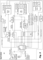
- FIG. 2 Other embodiments and/or aspects of this disclosure are shown in Fig. 2 .
- a control system 100 for a hybrid electric powerplant of an aircraft includes a heat engine controller 101 configured to receive one or more power settings (e.g., throttle and/or propeller setting, e.g., power lever angle (PLA) from a power lever 102) output and to determine a heat engine setting (e.g., a torque) and an electric motor setting (e.g., a torque).
- the heat engine controller 101 can be configured to use the heat engine setting to control a heat engine system 103 as a function of the heat engine setting to control torque output by a heat engine 105.
- the heat engine controller 101 is configured to output the electric motor setting.
- the system 100 includes an electric motor controller 107 that is operatively connected to the heat engine controller 101.
- the electric motor controller 107 is configured to receive the electric motor engine setting from the heat engine controller 101 and is configured to control an electric motor system 109, 111 (e.g., a battery management system and/or electric motor 111) as a function of the electric motor setting to control torque output by an electric motor 111.
- an electric motor system 109, 111 e.g., a battery management system and/or electric motor 111
- the system 100 includes a system protection module 101a that can be part of or connected to the heat engine controller 101 and is configured to provide one or more protection commands to directly control one or more heat engine protection systems 113 and one or more electric motor protection systems 115.
- the system protection module 101a can directly or indirectly connected to any suitable protection systems or other suitable control systems of any system of the powerplant to provide protection control thereto.
- the system protection module 101a can be integrated with and/or independent of the heat engine controller 101 in any suitable manner.
- the system 100 includes an electric motor protection module 107a that is part of the electric motor controller 107 and configured to provide one or more protection commands to directly control one or more electric motor protection systems 115.
- the system protection module 101a can be configured to provide powertrain level protection for the electric motor system and the electric motor protection module 107a can be configured to provide lane level protection to the electric motor system.
- the powertrain level protection can include uncontrollable high thrust protection (e.g., such that the system protection module 101a shuts down power to the electric motor 111 if thrust is above a threshold or determined to be out of control of the electric motor controller 107).
- the lane level protection can include overspeed, overcurrent, and/or over temperature protection (e.g., such that the electric motor protection module 107a shuts down power to the electric motor 111 if speed, current to the electric motor 111, and/or motor and/or battery temperature are above a threshold).
- the system protection module 101a can also be configured to provide heat engine overspeed and/or shaft shear protection in certain embodiments (e.g., such that the system protection module shuts off fuel flow to the heat engine 105 if speed and/or a strain on a shaft is above a threshold). Any other suitable protection types, system and/or lane level, e.g., as appreciated by those having ordinary skill in the art, are contemplated herein.
- the heat engine controller 101 can be configured to determine a propeller setting (e.g., based on a condition lever angle (CLA) or a selected propeller mode from a mode selector 117) and to use the propeller setting to control a propeller control system 119 (e.g., a PCU) as a function of the propeller setting to control a pitch of a propeller (e.g., via a hydraulic pitch control as appreciated by those having ordinary skill in the art in view of this disclosure).
- the system protection module 101a can be configured to provide one or more protection commands to directly control one or more propeller protection systems 123, for example.
- the heat engine controller 101 and/or the system protection module 101a can be operatively connected to each of the electric motor 111, the heat engine 105, and/or the propeller system 121 to receive feedback therefrom to provide control thereto (directly or indirectly) and/or protection control thereto (directly or indirectly).
- the electric motor protection module 107a can be operatively connected to the electric motor 111 (directly or indirectly) to receive electric motor feedback therefrom to provide protection control for the electric motor 111. Any suitable feedback, e.g., from any suitable sensor, is contemplated herein.
- the electric motor system 109 can include a battery management system (BMS), e.g., as shown.
- BMS battery management system
- the electric motor protection system 115 can include an electrical cutoff mechanism (e.g., a controllable contactor) disposed between the BMS 109 and the electric motor 111.
- the electrical cutoff mechanism e.g., a switch
- the electrical cutoff mechanism can be configured to be controlled by the electric motor protection module 107a and/ the system protection module 101a to cut off electrical energy to the electric motor 111 in a protection state, for example (e.g., overthrust, overcurrent, overspeed, etc.).
- the heat engine system 103 is a fuel control unit, e.g., as shown, for example.
- the heat engine protection system 113 can include a fuel shutoff valve (e.g., an overspeed valve) configured to be controlled by the system protection module 101a to cut off fuel flow to the fuel control unit 103 in a protection state, for example.
- a fuel shutoff valve e.g., an overspeed valve
- the propeller control system 119 can be a propeller control unit, e.g., as shown that can be configured to control a pitch of the propeller 121 (e.g., via a hydraulic oil system or any other suitable system).
- the propeller protection system 123 can include a feathering valve, e.g., as shown, configured to be controlled by the system protection module 101a to coarsen the pitch of (e.g., feather) the propeller 121 in a protection state, for example.
- the propeller protection system 123 can be configured to protect against propeller overspeed, propeller overtorque, and/or inadvertent operation in reverse propeller angle, for example. Any other suitable protection systems are contemplated herein.
- the electric motor controller 107 and/or the electric motor protection module 107a can be operatively connected to the heat engine controller 101 to provide controller operation feedback and/or respective system feedback to the heat engine controller.
- the heat engine controller 101 can include a thrust control module configured to divide a thrust command into an electric torque command for use by the electric motor controller 107 and a heat engine torque command for use by the heat engine controller 101 such that the electric engine settings include the electric torque command and the heat engine settings include a heat engine torque command.
- the heat engine controller 101 can include a propeller control module configured to receive a propeller mode setting (e.g., quite mode, cruise mode, max power mode) and to output a propeller setting (e.g., to the propeller control system 119) to achieve the selected propeller mode.
- a propeller mode setting e.g., quite mode, cruise mode, max power mode
- a propeller setting e.g., to the propeller control system 119
- the heat engine controller 101 can be configured to receive feedback from the electric motor protection module 107a for detection and/or reporting of a problem with the electric motor system to diagnose a cause and/or resolve the problem, e.g., by controlling a different system (e.g., the heat engine system).
- a different system e.g., the heat engine system
- the heat motor feedback, the electric motor feedback, and/or the propeller system feedback can include a torque value and/or a speed value.
- the heat engine feedback includes a temperature value for detecting heat engine fire. Any other suitable feedback is contemplated herein.
- ambient air data can be input to the heat engine controller 101 and/or to the system protection module 101a, e.g., from one or more air data sensors 125.
- the heat engine controller 101 and/or the system protection module 101a can be configured to use the ambient air data for control and/or protection control, respectively.
- air data can be provided to the electric motor controller 107 and/or the electric motor protection controller 107a. Any other suitable data flow and/or feedback flow is contemplated herein.
- the heat engine controller 101 can be configured to output one or more values of the feedback and/or air data to an aircraft cockpit display (e.g., battery state of charge, electric motor torque, heat engine torque, electric motor temperature, heat engine temperature), for example. Any suitable display and any suitable values are contemplated herein.
- an aircraft cockpit display e.g., battery state of charge, electric motor torque, heat engine torque, electric motor temperature, heat engine temperature
- the heat engine controller can be located in the fuselage of the aircraft and the electric motor controller can be located in the fuselage, wing, or HEP. In certain embodiments, the heat engine controller can be disposed within an avionics stack in a cockpit of the aircraft. Any suitable locations are contemplated herein.
- Certain embodiments do not include or require a separate thrust controller for splitting thrust commands between the heat engine controller and the electric motor controller as the heat engine controller (e.g., an ECU). Certain embodiments can provide flexibility for controlling propeller state as a function of ambient conditions and an input mode (e.g., quiet mode). For example, in certain embodiments, there is no propeller electronic controller (PEC) needed to decode a mode or CLA command as the heat engine controller can perform this function.
- PEC propeller electronic controller
- the system protection module (e.g., part of the heat engine controller) can also handle the protection for the thermal torque lane as well as the propeller system in certain embodiments.
- the system protection module (e.g., part of the heat engine controller) can also handle HEP level protection only for electric motor system (e.g., shut down due to high thrust condition, which can down the entire HEP), and all other protections can be performed by the electric motor protection module.
- Embodiments can reduce the number of controllers in the overall system 100, reducing size and weight of the system while maintaining functionality.
- the system can utilize a consolidated power command from the aircraft via a single lever (by setting a desired mode), the heat engine controller can be a primary command receiver, there may be no direct power command signal to the electric motor controller, there may be separate propeller control from engine control, and there may be no mechanical disconnect.
- the heat engine controlled can be the power and thrust command controller of the hybrid electric propulsion (HEP) system which includes an electric motor, heat motor, and a propeller system.
- the ECU can receive the pilot thrust/power command in the form of a Power Lever Angle (PLA) signal, the pilot commanded propeller speed in the form of the PLA signal, a propeller select signal to determine the propeller operation mode desired by the pilot, and the ambient air conditions from the aircraft signals, for example.
- PPA Power Lever Angle
- the ECU can use the aircraft signals to determine the power demand for the total HEP system and can split the demand into the commands to the electric motor (eM), heat motor (hM), and propeller systems.
- the speed governing of the HEP could be performed by the propeller control system or the hM control system.
- the ECU can translate the power command, ambient air conditions, and propeller mode select to determine the propeller blade angle (beta) and the power split between the hM and eM.
- Ambient air conditions can affect the thrust generated by the propeller and the hM performance.
- the ECU can have performance maps and models of the propeller and hM performance to determine the optimum motor and propeller operating points to meet the thrust command with the given propeller select mode.
- the ECU can manage interactions between the motors and the propeller system such as torque spikes.
- the ECU can send the fuel flow command to a Fuel Control Unit (FCU) to manage hM torque (Q_hm), the electric powertrain controller (EPC) can receive the torque command (Q_eM) from the ECU, and the ECU can send the beta command to the propeller control unit (PCU) to control the blade angle and ultimately the speed of the propeller speed.
- FCU Fuel Control Unit
- EPC electric powertrain controller
- Q_eM torque command
- PCU propeller control unit
- the ECU will also relay the overall operation of thermal engine effectors to meet the aircraft servicing needs (electrical power, bleed air, hydraulic power, etc.).
- the ECU can send the beta command to the PCU to drive the requested propeller speed.
- the cockpit can also send a beta pitch lock signal to the ECU and PCU, for example (e.g., from a manual input in the cockpit activated by a pilot).
- the beta lock can provide an indication when the PLA is in the reverse beta region. In the PCU, this can hydraulically unlock the region of the PCU to allow pressurization to the reverse beta blade angle range. In the ECU, it can allow a cross-reference with the PLA to determine whether the propeller system is permitted to enter the reverse beta region.
- Other propeller functions can be located in the ECU, for example. Any split of functionality between the PCU and the ECU are contemplated herein.
- the ECU can include separate electronics to perform the protection functions to protect against propeller overspeed, propeller overtorque, inadvertent reverse thrust/power, in-flight shutdown (IFSD), inability to autofeather, thermal engine overspeed (which can alternatively or additionally be implemented by mechanical protection means), thermal engine shaft shear (which can alternatively or additionally be implemented by mechanical protection means), and/or uncontrollable high thrust (UHT).
- IFSD in-flight shutdown
- thermal engine overspeed which can alternatively or additionally be implemented by mechanical protection means
- thermal engine shaft shear which can alternatively or additionally be implemented by mechanical protection means
- UHT uncontrollable high thrust
- All parameters affecting a control and protection function e.g. speed, torque, propeller blade angle, etc.
- can have completely independent means of measurement e.g. multiple probes or segregated means of measurement.
- similar requirements can be used to ensure that no single failure can result in a catastrophic or hazardous safety case.
- the ECU can have control over an overspeed valve (OSV), a battery contactor, and a feathering valve.
- OSV can provide a fuel shutoff means upstream of the fuel control unit (FCU) and can be used to shutdown the hM when required.
- the feathering valve can have the authority to coarsen the blade angle to "grab more air” to push the propeller out of certain critical operating areas.
- the battery contactor can cut off current from the battery system to the electric motor.
- the propeller, thermal engine, and at least some powertrain safety functions can be contained in the system protection module (e.g., ECU protection processor (ECU-PP)).
- ECU-PP ECU protection processor
- Propeller overspeed, auto feather, and reverse beta functions can be propeller protection functions contained the ECU-PP, for example.
- Thermal engine overspeed and shaft shear protection can be located in the ECU-PP, or designed in the thermal engine mechanical design, for example.
- the electric motor protection module e.g., EPC-PP
- the ECU-PP can perform powertrain-level protection functions such as uncontrollable high-thrust protection.
- Ambient air data, each power lane's torque and speed data, and the propeller operating conditions (speed, torque, and propeller angle) can be provided to the ECU-PP where the processor can compute the total output thrust.
- the ECU-PP can have the authority to shutdown each power lane and feather the propeller, for example. Protection means can be implemented to protect against hM failure cases resulting in engine and aircraft level safety cases. For example, in the event of an initiating event with the potential to lead to a hazardous or catastrophic event, the ECU-PP can cut off fuel flow using the OSV. Heat motor protection functions may include protection against non-containment of high-energy debris, shaft shear protection, overspeed protection, and/or protection against uncontrollable high thrust. Uncontrollable high thrust protection can involve understanding propeller and engine and motor interactions as they create thrust for the aircraft. The protection means could be implemented to both feather and shutdown the engine, for example. UHT protection may be required at high-power conditions such as takeoff in certain implementations. If the propeller blades were feathered at high power, it could lead to an overtorque condition. As a result, during high-power shutdown, the ECU-PP may sequence the motor shutoff first prior to feathering the propeller, for example.
- independent protection means for the propeller system may be utilized.
- the protection means for propeller system can depend on the potential hazard being mitigated.
- IFSD in-flight shutdown
- the propeller can be feathered to reduce the drag. Inability to feather after an IFSD on takeoff or climb could be potentially catastrophic.
- Protection means against a propeller overspeed and potential blade separation can also be provided by driving the propeller blade angle towards feather, coarsening the blade. By coarsening the blade angle, the propeller "grabs" more air and slows down as the rotational energy is transferred to torque. Protection against inadvertent operation in reverse beta region can be implemented in the ECU-PP as well, for example.
- Certain embodiments can provide a reduction in pilot workload for the start sequence.
- the HEP control system can automate starting functions to coordinate between the cockpit interface, the electric motor, and the heat engine.
- Single lever power control can greatly simplify the number of required inputs from the pilot and the required indications to monitor the engine start-up sequence.
- Certain embodiments can allow for reduction in pilot workload for most phases of flight. For example, single lever power control with the "mode select" can allow the pilot to control the propeller, electric motor, and thermal engine running speed through these two inputs, as opposed to two levers (e.g., a PLA and a CLA input).
- Integrating the control into a single unit can allow for greater access to data for the use of trend monitoring, maintenance diagnosis, and repair tools.
- the ECU can be able to monitor the operating data of all elements of the propulsion system to determine potential reductions in performance or negative trends in reliability.
- Certain embodiments can centralize control and protection functions to provide a system that can be easier to update and upgrade. Changes to the system can be performed in a more central place as opposed to updating each controller unit.
- Any controllers and/or modules described above can include any suitable hardware module(s) and/or software module(s). Any suitable controllers and/or modules can be independent of each other or can be hosted together and/or integrated together in any suitable manner (e.g., various software modules hosted on the same computer hardware).
- aspects of the present disclosure may be embodied as a system, method or computer program product. Accordingly, aspects of this disclosure may take the form of an entirely hardware embodiment, an entirely software embodiment (including firmware, resident software, micro-code, etc.), or an embodiment combining software and hardware aspects, all possibilities of which can be referred to herein as a "circuit,” “module,” or “system.”
- a “circuit,” “module,” or “system” can include one or more portions of one or more separate physical hardware and/or software components that can together perform the disclosed function of the "circuit,” “module,” or “system”, or a “circuit,” “module,” or “system” can be a single self-contained unit (e.g., of hardware and/or software).
- aspects of this disclosure may take the form of a computer program product embodied in one or more computer readable medium(s) having computer readable program code embodied thereon.
- the computer readable medium may be a computer readable signal medium or a computer readable storage medium.
- a computer readable storage medium may be, for example, but not limited to, an electronic, magnetic, optical, electromagnetic, infrared, or semiconductor system, apparatus, or device, or any suitable combination of the foregoing.
- a computer readable storage medium may be any tangible medium that can contain, or store a program for use by or in connection with an instruction execution system, apparatus, or device.
- a computer readable signal medium may include a propagated data signal with computer readable program code embodied therein, for example, in baseband or as part of a carrier wave. Such a propagated signal may take any of a variety of forms, including, but not limited to, electro-magnetic, optical, or any suitable combination thereof.
- a computer readable signal medium may be any computer readable medium that is not a computer readable storage medium and that can communicate, propagate, or transport a program for use by or in connection with an instruction execution system, apparatus, or device.
- Program code embodied on a computer readable medium may be transmitted using any appropriate medium, including but not limited to wireless, wireline, optical fiber cable, RF, etc., or any suitable combination of the foregoing.
- Computer program code for carrying out operations for aspects of this disclosure may be written in any combination of one or more programming languages, including an object oriented programming language such as Java, Smalltalk, C++ or the like and conventional procedural programming languages, such as the "C" programming language or similar programming languages.
- the program code may execute entirely on the user's computer, partly on the user's computer, as a stand-alone software package, partly on the user's computer and partly on a remote computer or entirely on the remote computer or server.
- the remote computer may be connected to the user's computer through any type of network, including a local area network (LAN) or a wide area network (WAN), or the connection may be made to an external computer (for example, through the Internet using an Internet Service Provider).
- LAN local area network
- WAN wide area network
- Internet Service Provider for example, AT&T, MCI, Sprint, EarthLink, MSN, GTE, etc.
- These computer program instructions may also be stored in a computer readable medium that can direct a computer, other programmable data processing apparatus, or other devices to function in a particular manner, such that the instructions stored in the computer readable medium produce an article of manufacture including instructions which implement the function/act specified in the flowchart and/or block diagram block or blocks.
- the computer program instructions may also be loaded onto a computer, other programmable data processing apparatus, or other devices to cause a series of operational steps to be performed on the computer, other programmable apparatus or other devices to produce a computer implemented process such that the instructions which execute on the computer or other programmable apparatus provide processes for implementing the functions/acts specified herein.
- any numerical values disclosed herein can be exact values or can be values within a range. Further, any terms of approximation (e.g., “about”, “approximately”, “around”) used in this disclosure can mean the stated value within a range. For example, in certain embodiments, the range can be within (plus or minus) 20%, or within 10%, or within 5%, or within 2%, or within any other suitable percentage or number as appreciated by those having ordinary skill in the art (e.g., for known tolerance limits or error ranges).
- a reference to "A and/or B", when used in conjunction with open-ended language such as “comprising” can refer, in one embodiment, to A only (optionally including elements other than B); in another embodiment, to B only (optionally including elements other than A); in yet another embodiment, to both A and B (optionally including other elements); etc.
Landscapes
- Engineering & Computer Science (AREA)
- Chemical & Material Sciences (AREA)
- Combustion & Propulsion (AREA)
- Aviation & Aerospace Engineering (AREA)
- Mechanical Engineering (AREA)
- General Engineering & Computer Science (AREA)
- Combined Controls Of Internal Combustion Engines (AREA)
Claims (15)
- Steuerungssystem (100) für einen hybriden elektrischen Antrieb eines Flugzeugs, umfassend:eine Wärmekraftmaschinensteuerung (101), die dazu konfiguriert ist, eine oder mehrere Leistungsbefehlseinstellungen von einem Leistungshebel (102) zu empfangen und eine Wärmekraftmaschineneinstellung und eine Elektromotoreinstellung zu bestimmen, wobei die Wärmekraftmaschinensteuerung (101) dazu konfiguriert ist, die Wärmekraftmaschineneinstellung zu verwenden, um eine Kraftstoffsteuereinheit (103) einer Wärmekraftmaschine (105) in Abhängigkeit von der Wärmekraftmaschineneinstellung zu steuern, indem ein Kraftstoffdurchflussbefehl an die Kraftstoffsteuereinheit (103) gesendet wird, um ein von der Wärmekraftmaschine (105) ausgegebenes Drehmoment zu steuern, wobei die Wärmekraftmaschinensteuerung (101) dazu konfiguriert ist, die Elektromotoreinstellung auszugeben;eine Elektromotorsteuerung (107), die mit der Wärmekraftmaschinensteuerung (101) wirkverbunden ist, wobei die Elektromotorsteuerung (107) dazu konfiguriert ist, die Elektromotoreinstellung von der Wärmekraftmaschinensteuerung (101) zu empfangen und ein Elektromotorsystem (109, 111) in Abhängigkeit von der Elektromotoreinstellung zu steuern, um die Drehmomentausgabe eines Elektromotors (111) zu steuern;ein Systemschutzmodul (101a), das Teil der Wärmekraftmaschinensteuerung (101) oder mit dieser verbunden ist und dazu konfiguriert ist, einen oder mehrere Schutzbefehle bereitzustellen, um ein oder mehrere Wärmekraftmaschinenschutzsysteme (113) und ein oder mehrere Elektromotorschutzsysteme (115) direkt zu steuern; undein Elektromotorschutzmodul (107a), das Teil der Elektromotorsteuerung (107) und dazu konfiguriert ist, einen oder mehrere Schutzbefehle bereitzustellen, um das eine oder die mehreren Elektromotorschutzsysteme (115) direkt zu steuern.
- System (100) nach Anspruch 1, wobei das Elektromotorschutzmodul (107a) dazu konfiguriert ist, dem Elektromotorsystem (109, 111) einen Schutz auf Bahnebene bereitzustellen, wobei der Schutz auf Bahnebene optional einen Überdrehzahl-, Überstrom- und/oder Übertemperaturschutz beinhaltet.
- System (100) nach Anspruch 1 oder 2, wobei die Wärmekraftmaschinensteuerung (101) und/oder das Systemschutzmodul (101a) mit jedem von dem Elektromotor (111), der Wärmekraftmaschine (105) und/oder einem Propellersystem (121) wirkverbunden ist, um Rückmeldungen von diesen zu empfangen und/oder diesen eine Steuerung bereitzustellen, wobei das Elektromotorschutzmodul (107a) mit dem Elektromotor (111) wirkverbunden ist, um Elektromotorrückmeldungen von diesem zu empfangen, um eine Schutzsteuerung für den Elektromotor (111) bereitzustellen.
- System (100) nach Anspruch 3, wobei:die Wärmekraftmaschinenrückmeldungen einen Temperaturwert zum Erkennen eines Feuers der Wärmekraftmaschine beinhalten; und/oderdie Wärmekraftmaschinenrückmeldungen, die Elektromotorrückmeldungen und/oder die Propellersystemrückmeldungen einen Drehmomentwert und/oder einen Drehzahlwert beinhalten.
- System (100) nach einem der vorhergehenden Ansprüche, wobei das Elektromotorsystem (109, 111) ein Batteriemanagementsystem (BMS) (109) beinhaltet, wobei das Elektromotorschutzsystem (115) einen elektrischen Abschaltmechanismus beinhaltet, der zwischen dem BMS (109) und dem Elektromotor (111) angeordnet ist, wobei der elektrische Abschaltmechanismus (115) dazu konfiguriert ist, durch das Elektromotorschutzmodul (107a) und das Systemschutzmodul (101a) gesteuert zu werden, um in einem Schutzzustand elektrische Energie an den Elektromotor (111) abzuschalten.
- System (100) nach einem der vorhergehenden Ansprüche, wobei die Wärmekraftmaschinensteuerung (101) dazu konfiguriert ist, Rückmeldungen von dem Elektromotorschutzmodul (107a) zur Erkennung und/oder Meldung eines Problems mit dem Elektromotorsystem (109, 111) zu empfangen, um eine Ursache zu diagnostizieren und/oder das Problem zu lösen, indem ein anderes System gesteuert wird.
- System (100) nach einem der vorhergehenden Ansprüche, wobei das Systemschutzmodul (101a) dazu konfiguriert ist, einen Schutz auf Antriebsstrangebene für das Elektromotorsystem (109, 111) bereitzustellen, wobei der Schutz auf Antriebsstrangebene optional einen Schutz vor unkontrollierbarem hohem Schub beinhaltet.
- System (100) nach einem der vorhergehenden Ansprüche, wobei das Systemschutzmodul (101a) dazu konfiguriert ist, Folgendes bereitzustellen:Schutz vor Überdrehzahl und/oder Wellenabscherung der Wärmekraftmaschine; und/oderein oder mehrere Schutzbefehle, um eines oder mehrerer Propellerschutzsysteme (123) direkt zu steuern.
- System (100) nach einem der vorhergehenden Ansprüche, wobei die Wärmekraftmaschinensteuerung (101) dazu konfiguriert ist, eine Propellereinstellung zu bestimmen und die Propellereinstellung zu verwenden, um ein Propellersteuerungssystem (119) in Abhängigkeit von der Propellereinstellung zu steuern.
- System (100) nach Anspruch 9, wobei das Propellersteuerungssystem (119) eine Propellersteuerungseinheit ist, die dazu konfiguriert ist, eine Steigung eines Propellers (121) zu steuern, und das Propellerschutzsystem (123) ein Segelstellungsventil beinhaltet, das dazu konfiguriert ist, durch das Systemschutzmodul (101a) gesteuert zu werden, um die Propellersteigung in einen Schutzzustand zu erhöhen.
- System (100) nach einem der vorhergehenden Ansprüche, wobei das Wärmekraftmaschinenschutzsystem (113) ein Kraftstoffabschaltventil beinhaltet, das dazu konfiguriert ist, durch das Systemschutzmodul (101a) gesteuert zu werden, um den Kraftstoffdurchfluss zu der Kraftstoffsteuereinheit (103) in einem Schutzzustand abzuschalten.
- System (100) nach einem der vorhergehenden Ansprüche, wobei die Elektromotorsteuerung (107) und/oder das Elektromotorschutzmodul (107a) mit der Wärmekraftmaschinensteuerung (101) wirkverbunden ist/sind, um Steuerungsbetriebsrückmeldungen und/oder jeweilige Systemrückmeldungen an die Wärmekraftmaschinensteuerung (101) bereitzustellen.
- System (100) nach einem der vorhergehenden Ansprüche, wobei die Wärmekraftmaschinensteuerung (101) Folgendes beinhaltet:Schubsteuerungsmodul, das dazu konfiguriert ist, einen Schubbefehl in einen elektrischen Drehmomentbefehl zur Verwendung durch die Elektromotorsteuerung (107) und einen Wärmekraftmaschinendrehmomentbefehl zur Verwendung durch die Wärmekraftmaschinensteuerung (101) aufzuteilen, derart, dass die Elektromotoreinstellungen den elektrischen Drehmomentbefehl beinhalten und die Wärmekraftmaschineneinstellungen einen Wärmekraftmaschinendrehmomentbefehl beinhalten; und/oderein Propellersteuerungsmodul, das dazu konfiguriert ist, eine Propellermoduseinstellung zu empfangen und eine Propellereinstellung auszugeben, um den ausgewählten Propellermodus zu erreichen.
- System (100) nach einem der vorhergehenden Ansprüche, wobei Umgebungsluftdaten in die Wärmekraftmaschinensteuerung (101) und/oder in das Systemschutzmodul (101a) eingegeben werden, wobei die Wärmekraftmaschinensteuerung (101) und/oder das Systemschutzmodul (101a) dazu konfiguriert sind, die Umgebungsluftdaten für die Steuerung bzw. Schutzsteuerung zu verwenden.
- Verfahren zum Steuern eines hybriden elektrischen Antriebs eines Flugzeugs, umfassend:Empfangen einer oder mehrerer Leistungsbefehlseinstellungen von einem Leistungshebel (102) des Flugzeugs an einer Wärmekraftmaschinensteuerung (101);Steuern eines Elektromotors (111) mit einer Elektromotorsteuerung (107);Steuern einer Wärmekraftmaschine (105) mit der Wärmekraftmaschinensteuerung (101) durch Senden eines Kraftstoffdurchflussbefehls von der Wärmekraftmaschinensteuerung (101) an eine Kraftstoffsteuereinheit der Wärmekraftmaschine (105), um ein von der Wärmekraftmaschine (105) ausgegebenes Drehmoment zu steuern; Bereitstellen eines Elektromotordrehmomentbefehls an die Elektromotorsteuerung (107) von der Wärmekraftmaschinensteuerung (101);Bereitstellen eines Überdrehzahl- oder Überdrehmomentschutzes für den Elektromotor (111) mit einem Elektromotorschutzmodul (107a), das Teil der Elektromotorsteuerung (107) ist;Bereitstellen eines Überdrehzahl- oder Überdrehmomentschutzes für die Wärmekraftmaschine (105) mit einem Systemschutzmodul (101a), das Teil der Wärmekraftmaschinensteuerung (101) oder mit dieser verbunden ist; undBereitstellen eines Schutzes vor unkontrollierbarem Schub für den Elektromotor (111) unter Verwendung des Systemschutzmoduls (101a).
Applications Claiming Priority (1)
| Application Number | Priority Date | Filing Date | Title |
|---|---|---|---|
| US16/875,911 US11760495B2 (en) | 2020-05-15 | 2020-05-15 | Control systems for hybrid electric power plants |
Publications (2)
| Publication Number | Publication Date |
|---|---|
| EP3909856A1 EP3909856A1 (de) | 2021-11-17 |
| EP3909856B1 true EP3909856B1 (de) | 2024-12-18 |
Family
ID=75936892
Family Applications (1)
| Application Number | Title | Priority Date | Filing Date |
|---|---|---|---|
| EP21174143.4A Active EP3909856B1 (de) | 2020-05-15 | 2021-05-17 | Steuerungssysteme für hybride elektrische antriebe |
Country Status (4)
| Country | Link |
|---|---|
| US (1) | US11760495B2 (de) |
| EP (1) | EP3909856B1 (de) |
| CA (1) | CA3119006A1 (de) |
| PL (1) | PL3909856T3 (de) |
Families Citing this family (8)
| Publication number | Priority date | Publication date | Assignee | Title |
|---|---|---|---|---|
| US11845551B2 (en) * | 2021-02-26 | 2023-12-19 | Beta Air, Llc | Methods and system for estimating percentage torque produced by a propulsor configured for use in an electric aircraft |
| FR3130757B1 (fr) * | 2021-12-17 | 2023-12-22 | Safran Helicopter Engines | Procédé de régulation de la vitesse de rotation d’un propulseur d’un groupe propulsif hybride pour aéronef, en situation de panne du système de régulation principal du moteur thermique du groupe propulsif hybride |
| US11965424B2 (en) | 2022-06-21 | 2024-04-23 | General Electric Company | Electronic overspeed protection system and method |
| US12300991B2 (en) * | 2022-10-04 | 2025-05-13 | Pratt & Whitney Canada Corp. | Overspeed and/or overtorque protection for hybrid electric aircraft propulsion system |
| US12473843B2 (en) * | 2023-02-13 | 2025-11-18 | Pratt & Whitney Canada Corp. | Hybrid electric propulsion system with pitch change mechanism operation |
| US12030657B1 (en) * | 2023-10-27 | 2024-07-09 | Rtx Corporation | System and methods for power split algorithm design for aircraft hybrid electric propulsion based on combined actor-critic RL agent and control barrier function filter |
| US12545418B2 (en) * | 2024-07-03 | 2026-02-10 | Pratt & Whitney Canada Corp. | Control assembly for aircraft propulsion systems |
| US12545419B1 (en) * | 2024-12-30 | 2026-02-10 | Pratt & Whitney Canada Corp. | Emergency energy protection assembly for hybrid-electric aircraft propulsion systems |
Citations (2)
| Publication number | Priority date | Publication date | Assignee | Title |
|---|---|---|---|---|
| US20120209456A1 (en) * | 2011-02-15 | 2012-08-16 | Government Of The United States, As Represented By The Secretary Of The Air Force | Parallel Hybrid-Electric Propulsion Systems for Unmanned Aircraft |
| EP3927620A1 (de) * | 2019-04-25 | 2021-12-29 | Pratt & Whitney Canada Corp. | Steuerungssysteme für elektrische hybridkraftwerke |
Family Cites Families (4)
| Publication number | Priority date | Publication date | Assignee | Title |
|---|---|---|---|---|
| WO2016093905A1 (en) * | 2014-08-29 | 2016-06-16 | Tzunum Aircraft Llc | System and methods for implementing regional air transit network using hybrid-electric aircraft |
| US10006375B1 (en) | 2017-07-11 | 2018-06-26 | General Electric Company | Propulsion system for an aircraft |
| US11332256B2 (en) | 2018-08-21 | 2022-05-17 | General Electric Company | Fault tolerant hybrid electric propulsion system for an aerial vehicle |
| US11015480B2 (en) * | 2018-08-21 | 2021-05-25 | General Electric Company | Feed forward load sensing for hybrid electric systems |
-
2020
- 2020-05-15 US US16/875,911 patent/US11760495B2/en active Active
-
2021
- 2021-05-17 PL PL21174143.4T patent/PL3909856T3/pl unknown
- 2021-05-17 EP EP21174143.4A patent/EP3909856B1/de active Active
- 2021-05-17 CA CA3119006A patent/CA3119006A1/en active Pending
Patent Citations (2)
| Publication number | Priority date | Publication date | Assignee | Title |
|---|---|---|---|---|
| US20120209456A1 (en) * | 2011-02-15 | 2012-08-16 | Government Of The United States, As Represented By The Secretary Of The Air Force | Parallel Hybrid-Electric Propulsion Systems for Unmanned Aircraft |
| EP3927620A1 (de) * | 2019-04-25 | 2021-12-29 | Pratt & Whitney Canada Corp. | Steuerungssysteme für elektrische hybridkraftwerke |
Also Published As
| Publication number | Publication date |
|---|---|
| US11760495B2 (en) | 2023-09-19 |
| EP3909856A1 (de) | 2021-11-17 |
| PL3909856T3 (pl) | 2025-03-10 |
| US20210354837A1 (en) | 2021-11-18 |
| CA3119006A1 (en) | 2021-11-15 |
Similar Documents
| Publication | Publication Date | Title |
|---|---|---|
| EP3909856B1 (de) | Steuerungssysteme für hybride elektrische antriebe | |
| EP3927620B1 (de) | Steuerungssysteme für elektrische hybridkraftwerke | |
| EP3909857B1 (de) | Steuerungssysteme für hybride elektrizitätswerke | |
| EP3936712B1 (de) | Steuerungsarchitektur für hybrides elektrisches kraftwerk | |
| US20200277064A1 (en) | Degraded mode operation of hybrid electric propulsion systems | |
| EP4032812B1 (de) | Verfahren und systeme zur leistungsverwaltung eines hybriden elektrischen antriebs | |
| WO2017015341A1 (en) | Control system for rotorcraft in-flight engine restarting | |
| EP3909858B1 (de) | Schutzfunktionen | |
| US20180065738A1 (en) | Autorotation initiation system | |
| US12510020B2 (en) | Hybrid-electric propulsion system equipped with a coupler for switching between modes of operation | |
| EP4480826A1 (de) | Verfahren und system zur abschwächung eines elektromotorfehlers in einem flugzeugkraftwerk | |
| EP4350135A2 (de) | Überdrehzahl- und/oder drehmomentschutz für ein hybrides elektrisches flugzeugantriebssystem | |
| US20220194555A1 (en) | System and method for detecting propeller malfunction | |
| EP4101755B1 (de) | Zusätzliche motorleistungssteuerung | |
| US9522740B2 (en) | Method and a device for protecting an overspeeding rotorcraft engine | |
| US20240377838A1 (en) | Method and device for entering and exiting an economy operating mode for a twin-engine aircraft | |
| CN118774989A (zh) | 一种单发无人直升机发动机动力涡轮超转保护方法及系统 | |
| EP4620820A1 (de) | Verfahren zum antrieb eines hybridflugzeugs beim start |
Legal Events
| Date | Code | Title | Description |
|---|---|---|---|
| PUAI | Public reference made under article 153(3) epc to a published international application that has entered the european phase |
Free format text: ORIGINAL CODE: 0009012 |
|
| STAA | Information on the status of an ep patent application or granted ep patent |
Free format text: STATUS: THE APPLICATION HAS BEEN PUBLISHED |
|
| AK | Designated contracting states |
Kind code of ref document: A1 Designated state(s): AL AT BE BG CH CY CZ DE DK EE ES FI FR GB GR HR HU IE IS IT LI LT LU LV MC MK MT NL NO PL PT RO RS SE SI SK SM TR |
|
| B565 | Issuance of search results under rule 164(2) epc |
Effective date: 20211013 |
|
| STAA | Information on the status of an ep patent application or granted ep patent |
Free format text: STATUS: REQUEST FOR EXAMINATION WAS MADE |
|
| 17P | Request for examination filed |
Effective date: 20220321 |
|
| RBV | Designated contracting states (corrected) |
Designated state(s): AL AT BE BG CH CY CZ DE DK EE ES FI FR GB GR HR HU IE IS IT LI LT LU LV MC MK MT NL NO PL PT RO RS SE SI SK SM TR |
|
| STAA | Information on the status of an ep patent application or granted ep patent |
Free format text: STATUS: EXAMINATION IS IN PROGRESS |
|
| 17Q | First examination report despatched |
Effective date: 20230328 |
|
| GRAP | Despatch of communication of intention to grant a patent |
Free format text: ORIGINAL CODE: EPIDOSNIGR1 |
|
| STAA | Information on the status of an ep patent application or granted ep patent |
Free format text: STATUS: GRANT OF PATENT IS INTENDED |
|
| RIC1 | Information provided on ipc code assigned before grant |
Ipc: B64D 27/02 20060101ALN20240703BHEP Ipc: F02C 9/28 20060101ALI20240703BHEP Ipc: B64D 31/00 20060101ALI20240703BHEP Ipc: B64D 27/24 20060101AFI20240703BHEP |
|
| INTG | Intention to grant announced |
Effective date: 20240712 |
|
| GRAS | Grant fee paid |
Free format text: ORIGINAL CODE: EPIDOSNIGR3 |
|
| GRAA | (expected) grant |
Free format text: ORIGINAL CODE: 0009210 |
|
| STAA | Information on the status of an ep patent application or granted ep patent |
Free format text: STATUS: THE PATENT HAS BEEN GRANTED |
|
| AK | Designated contracting states |
Kind code of ref document: B1 Designated state(s): AL AT BE BG CH CY CZ DE DK EE ES FI FR GB GR HR HU IE IS IT LI LT LU LV MC MK MT NL NO PL PT RO RS SE SI SK SM TR |
|
| REG | Reference to a national code |
Ref country code: CH Ref legal event code: EP |
|
| REG | Reference to a national code |
Ref country code: DE Ref legal event code: R096 Ref document number: 602021023438 Country of ref document: DE |
|
| REG | Reference to a national code |
Ref country code: IE Ref legal event code: FG4D |
|
| REG | Reference to a national code |
Ref country code: LT Ref legal event code: MG9D |
|
| PG25 | Lapsed in a contracting state [announced via postgrant information from national office to epo] |
Ref country code: HR Free format text: LAPSE BECAUSE OF FAILURE TO SUBMIT A TRANSLATION OF THE DESCRIPTION OR TO PAY THE FEE WITHIN THE PRESCRIBED TIME-LIMIT Effective date: 20241218 |
|
| PG25 | Lapsed in a contracting state [announced via postgrant information from national office to epo] |
Ref country code: FI Free format text: LAPSE BECAUSE OF FAILURE TO SUBMIT A TRANSLATION OF THE DESCRIPTION OR TO PAY THE FEE WITHIN THE PRESCRIBED TIME-LIMIT Effective date: 20241218 |
|
| PG25 | Lapsed in a contracting state [announced via postgrant information from national office to epo] |
Ref country code: BG Free format text: LAPSE BECAUSE OF FAILURE TO SUBMIT A TRANSLATION OF THE DESCRIPTION OR TO PAY THE FEE WITHIN THE PRESCRIBED TIME-LIMIT Effective date: 20241218 |
|
| PG25 | Lapsed in a contracting state [announced via postgrant information from national office to epo] |
Ref country code: NO Free format text: LAPSE BECAUSE OF FAILURE TO SUBMIT A TRANSLATION OF THE DESCRIPTION OR TO PAY THE FEE WITHIN THE PRESCRIBED TIME-LIMIT Effective date: 20250318 |
|
| REG | Reference to a national code |
Ref country code: NL Ref legal event code: MP Effective date: 20241218 |
|
| PG25 | Lapsed in a contracting state [announced via postgrant information from national office to epo] |
Ref country code: LV Free format text: LAPSE BECAUSE OF FAILURE TO SUBMIT A TRANSLATION OF THE DESCRIPTION OR TO PAY THE FEE WITHIN THE PRESCRIBED TIME-LIMIT Effective date: 20241218 Ref country code: GR Free format text: LAPSE BECAUSE OF FAILURE TO SUBMIT A TRANSLATION OF THE DESCRIPTION OR TO PAY THE FEE WITHIN THE PRESCRIBED TIME-LIMIT Effective date: 20250319 |
|
| PG25 | Lapsed in a contracting state [announced via postgrant information from national office to epo] |
Ref country code: RS Free format text: LAPSE BECAUSE OF FAILURE TO SUBMIT A TRANSLATION OF THE DESCRIPTION OR TO PAY THE FEE WITHIN THE PRESCRIBED TIME-LIMIT Effective date: 20250318 |
|
| PG25 | Lapsed in a contracting state [announced via postgrant information from national office to epo] |
Ref country code: NL Free format text: LAPSE BECAUSE OF FAILURE TO SUBMIT A TRANSLATION OF THE DESCRIPTION OR TO PAY THE FEE WITHIN THE PRESCRIBED TIME-LIMIT Effective date: 20241218 |
|
| REG | Reference to a national code |
Ref country code: AT Ref legal event code: MK05 Ref document number: 1752072 Country of ref document: AT Kind code of ref document: T Effective date: 20241218 |
|
| PG25 | Lapsed in a contracting state [announced via postgrant information from national office to epo] |
Ref country code: SM Free format text: LAPSE BECAUSE OF FAILURE TO SUBMIT A TRANSLATION OF THE DESCRIPTION OR TO PAY THE FEE WITHIN THE PRESCRIBED TIME-LIMIT Effective date: 20241218 |
|
| PGFP | Annual fee paid to national office [announced via postgrant information from national office to epo] |
Ref country code: PL Payment date: 20250424 Year of fee payment: 5 Ref country code: DE Payment date: 20250423 Year of fee payment: 5 |
|
| PG25 | Lapsed in a contracting state [announced via postgrant information from national office to epo] |
Ref country code: ES Free format text: LAPSE BECAUSE OF FAILURE TO SUBMIT A TRANSLATION OF THE DESCRIPTION OR TO PAY THE FEE WITHIN THE PRESCRIBED TIME-LIMIT Effective date: 20241218 |
|
| PGFP | Annual fee paid to national office [announced via postgrant information from national office to epo] |
Ref country code: GB Payment date: 20250423 Year of fee payment: 5 |
|
| PG25 | Lapsed in a contracting state [announced via postgrant information from national office to epo] |
Ref country code: IS Free format text: LAPSE BECAUSE OF FAILURE TO SUBMIT A TRANSLATION OF THE DESCRIPTION OR TO PAY THE FEE WITHIN THE PRESCRIBED TIME-LIMIT Effective date: 20250418 |
|
| PG25 | Lapsed in a contracting state [announced via postgrant information from national office to epo] |
Ref country code: PT Free format text: LAPSE BECAUSE OF FAILURE TO SUBMIT A TRANSLATION OF THE DESCRIPTION OR TO PAY THE FEE WITHIN THE PRESCRIBED TIME-LIMIT Effective date: 20250421 |
|
| PG25 | Lapsed in a contracting state [announced via postgrant information from national office to epo] |
Ref country code: EE Free format text: LAPSE BECAUSE OF FAILURE TO SUBMIT A TRANSLATION OF THE DESCRIPTION OR TO PAY THE FEE WITHIN THE PRESCRIBED TIME-LIMIT Effective date: 20241218 |
|
| PGFP | Annual fee paid to national office [announced via postgrant information from national office to epo] |
Ref country code: FR Payment date: 20250423 Year of fee payment: 5 |
|
| PG25 | Lapsed in a contracting state [announced via postgrant information from national office to epo] |
Ref country code: AT Free format text: LAPSE BECAUSE OF FAILURE TO SUBMIT A TRANSLATION OF THE DESCRIPTION OR TO PAY THE FEE WITHIN THE PRESCRIBED TIME-LIMIT Effective date: 20241218 Ref country code: RO Free format text: LAPSE BECAUSE OF FAILURE TO SUBMIT A TRANSLATION OF THE DESCRIPTION OR TO PAY THE FEE WITHIN THE PRESCRIBED TIME-LIMIT Effective date: 20241218 |
|
| PG25 | Lapsed in a contracting state [announced via postgrant information from national office to epo] |
Ref country code: SK Free format text: LAPSE BECAUSE OF FAILURE TO SUBMIT A TRANSLATION OF THE DESCRIPTION OR TO PAY THE FEE WITHIN THE PRESCRIBED TIME-LIMIT Effective date: 20241218 |
|
| PGFP | Annual fee paid to national office [announced via postgrant information from national office to epo] |
Ref country code: CZ Payment date: 20250429 Year of fee payment: 5 |
|
| PG25 | Lapsed in a contracting state [announced via postgrant information from national office to epo] |
Ref country code: IT Free format text: LAPSE BECAUSE OF FAILURE TO SUBMIT A TRANSLATION OF THE DESCRIPTION OR TO PAY THE FEE WITHIN THE PRESCRIBED TIME-LIMIT Effective date: 20241218 |
|
| PG25 | Lapsed in a contracting state [announced via postgrant information from national office to epo] |
Ref country code: SE Free format text: LAPSE BECAUSE OF FAILURE TO SUBMIT A TRANSLATION OF THE DESCRIPTION OR TO PAY THE FEE WITHIN THE PRESCRIBED TIME-LIMIT Effective date: 20241218 |
|
| REG | Reference to a national code |
Ref country code: DE Ref legal event code: R097 Ref document number: 602021023438 Country of ref document: DE |
|
| PG25 | Lapsed in a contracting state [announced via postgrant information from national office to epo] |
Ref country code: DK Free format text: LAPSE BECAUSE OF FAILURE TO SUBMIT A TRANSLATION OF THE DESCRIPTION OR TO PAY THE FEE WITHIN THE PRESCRIBED TIME-LIMIT Effective date: 20241218 |
|
| PLBE | No opposition filed within time limit |
Free format text: ORIGINAL CODE: 0009261 |
|
| STAA | Information on the status of an ep patent application or granted ep patent |
Free format text: STATUS: NO OPPOSITION FILED WITHIN TIME LIMIT |
|
| REG | Reference to a national code |
Ref country code: CH Ref legal event code: L10 Free format text: ST27 STATUS EVENT CODE: U-0-0-L10-L00 (AS PROVIDED BY THE NATIONAL OFFICE) Effective date: 20251029 |
|
| 26N | No opposition filed |
Effective date: 20250919 |
|
| REG | Reference to a national code |
Ref country code: CH Ref legal event code: H13 Free format text: ST27 STATUS EVENT CODE: U-0-0-H10-H13 (AS PROVIDED BY THE NATIONAL OFFICE) Effective date: 20251223 |
|
| PG25 | Lapsed in a contracting state [announced via postgrant information from national office to epo] |
Ref country code: LU Free format text: LAPSE BECAUSE OF NON-PAYMENT OF DUE FEES Effective date: 20250517 |
|
| PG25 | Lapsed in a contracting state [announced via postgrant information from national office to epo] |
Ref country code: CH Free format text: LAPSE BECAUSE OF NON-PAYMENT OF DUE FEES Effective date: 20250531 |
|
| PG25 | Lapsed in a contracting state [announced via postgrant information from national office to epo] |
Ref country code: MC Free format text: LAPSE BECAUSE OF FAILURE TO SUBMIT A TRANSLATION OF THE DESCRIPTION OR TO PAY THE FEE WITHIN THE PRESCRIBED TIME-LIMIT Effective date: 20241218 |