EP3909810A1 - Clamping structure of cargo support - Google Patents
Clamping structure of cargo support Download PDFInfo
- Publication number
- EP3909810A1 EP3909810A1 EP20203439.3A EP20203439A EP3909810A1 EP 3909810 A1 EP3909810 A1 EP 3909810A1 EP 20203439 A EP20203439 A EP 20203439A EP 3909810 A1 EP3909810 A1 EP 3909810A1
- Authority
- EP
- European Patent Office
- Prior art keywords
- guide
- cross beam
- chuck
- guide portion
- cargo support
- Prior art date
- Legal status (The legal status is an assumption and is not a legal conclusion. Google has not performed a legal analysis and makes no representation as to the accuracy of the status listed.)
- Granted
Links
Images





Classifications
-
- B—PERFORMING OPERATIONS; TRANSPORTING
- B60—VEHICLES IN GENERAL
- B60P—VEHICLES ADAPTED FOR LOAD TRANSPORTATION OR TO TRANSPORT, TO CARRY, OR TO COMPRISE SPECIAL LOADS OR OBJECTS
- B60P7/00—Securing or covering of load on vehicles
- B60P7/06—Securing of load
-
- B—PERFORMING OPERATIONS; TRANSPORTING
- B60—VEHICLES IN GENERAL
- B60P—VEHICLES ADAPTED FOR LOAD TRANSPORTATION OR TO TRANSPORT, TO CARRY, OR TO COMPRISE SPECIAL LOADS OR OBJECTS
- B60P7/00—Securing or covering of load on vehicles
- B60P7/06—Securing of load
- B60P7/135—Securing or supporting by load bracing means
- B60P7/15—Securing or supporting by load bracing means the load bracing means comprising a movable bar
Definitions
- the invention belongs to the technical field of logistics transportation equipment, and relates to a cargo support, and more particularly to a clamping structure of a cargo support.
- the China patent titled "F-shaped cargo clamp and manufacturing method thereof" discloses a structure of a cargo support, the cargo support includes a square tube (i.e. a cross beam) and two sets of F-shaped cargo clamps respectively disposed at two ends of the square tube.
- the F-shaped cargo clamp includes a bracket, a clamp plate and a handle.
- the bracket is L-shaped and composed of a static clamp plate and a positioning plate that are connected integrally.
- the two F-shaped cargo clamps are respectively connected to the two ends of the square tube through the bracket.
- the cargo support has the following drawbacks in usage practically.
- the F-shaped cargo clamps are connected with the cross beam through a plurality of connecting holes disposed in the brackets of the F-shaped cargo clamps.
- the cross beam is inserted into the brackets and rivets are used to pass through the connecting holes to realize connection between the cross beam and the F-shaped cargo clamps.
- most of the structures of the F-shaped cargo clamp such as a movable clamp plate, a sliding rod, a large spring, a small spring, and a guide structure for guiding the movable clamp plate are all entirely exposed, which causes poor aesthetics of the cargo support as a whole due to exposure of many parts of the cargo support.
- the handle needs to be pulled to drive the clamp plate to protrude and retract.
- the guide structure adopted is as follows: a raised link plate is disposed on a back of the positioning plate, the link plate has two sliding grooves with openings disposed back-to-back, an elongated groove with an opening at one end is disposed on a connecting plate of the movable clamp plate, and the link plate is sleeved in the elongated groove and can slide back and forth along the elongated groove.
- the impurities can easily enter contact parts between the movable clamp plates and the sliding grooves with openings. After a long time usage, the impurities will affect smooth movement of the movable clamp plates, resulting in greatly affecting smooth operation of the cargo clamps.
- the elongated groove with the opening at one end is provided on the connecting plate, and during operation of the handle, the link plate needs to slide back and forth along the elongated groove; with such configuration of the structure, in case an operator's hands inserts into the elongated groove incautiously, the hand will be caught easily, so there is a factor of poor safety.
- one object of one embodiment of the invention is to disclose a clamping structure for a cargo support, the invention solves the problem of poor movement stability of a chuck of the existing cargo support.
- a clamping structure of a cargo support having a cross beam comprising: a chuck with a guide portion and disposed at an end of the cross beam, the cross beam being connected with a handle, the handle being capable of driving the chuck to move back and forth along an axial direction of the cross beam so that the chuck switching between a clamped state and a released state, wherein the cross beam is of hollow structure, the guide portion of the chuck extends into the cross beam, and inside the cross beam is further provided with a guide structure that cooperates with the guide portion and guides a movement of the chuck.
- the guide portion of the chuck extends into the cross beam, so that the guide portion of the chuck moves inside the cross beam.
- the guide structure that cooperating with the guide portion also disposed inside the cross beam, avoiding a part of the guide structure cooperating with the guide portion to be directly exposed to the outside, so that the guide structure is not easily interfered by external impurities and always maintains high guiding stability, ultimately ensuring that the chuck is capable of moving more stably and smoothly, making the cargo support stable during usage and operate smoothly.
- a first top plate located on an upper side of the guide structure is provided on the cross beam.
- a top of the cross beam further has a gap
- a link is provided in the cross beam
- one end of the handle extends into the gap and is articulated on an inner wall of the cross beam
- the link is connected with the handle and the link is also connected with the guide portion of the chuck
- the handle drives the chuck to move through the link.
- Such a design makes the guide portion of the chuck that connects with the link, and the guide structure that cooperates with the guide portion to be capable of being conveniently disposed inside the cross beam, ultimately achieving an object of improving a movement stability of the chuck.
- such a structure also avoids many components being exposed to the outside, making the cargo support more aesthetic as a whole, more likely to be favored by consumers, and enhancing market competitiveness.
- the guide structure is a guide sleeve fixed inside the cross beam, and the guide portion of the chuck passes through the guide sleeve and forms a sliding fit with the guide sleeve.
- the guide sleeve and the guide portion of the chuck By forming a sliding fit between the guide sleeve and the guide portion of the chuck to guide a movement of the chuck, the movement of the chuck is stable and smooth.
- influence of external impurities on fitting surfaces between the guide sleeve and the guide portion can be effectively reduced, thereby improving a stability of guiding, and ensuring stable movement of the chuck.
- the at least one brace located below the guide portion is fixedly connected inside the cross beam, the cross beam is provided with a first top plate located on an upper side of the guide sleeve, a bottom of the guide sleeve is connected on the at least one brace, and a top of the guide sleeve abuts and positions on the first top plate.
- the guide portion of the chuck includes two vertically disposed side guide plates and an upper guide plate connecting between top edges of the two side guide plates, the guide sleeve is made of plastic material, the guide sleeve has a through hole penetrating through both ends, a limit portion extending along a longitudinal direction of the through hole is further disposed on a bottom wall of the through hole, an upside down U-channel guide matching the guide portion is formed between an outer wall of the limit portion and a hole wall of the through hole, and the guide portion is slidably inserted in the upside down U-channel guide.
- the guide portion includes the two side guide plates and the upper guide plate, such a structure matches with the upside down U-channel guide to enable a larger matching area between the guide sleeve and the guide portion, thereby increasing stability and precision of guiding, and ensuring stable movement of the chuck.
- a shape is more complicated; however, having the guide sleeve made of plastic material, it is easy to mold the guide sleeve into a structure with a complicated shape, which reduces the manufacturing costs on the basis of ensuring a guiding precision.
- the two braces are disposed at a same height and are spaced apart from each other, the bottom of the guide sleeve is provided with underpinnings at positions corresponding to each of the two braces, and the underpinnings are respectively sleeved on corresponding braces.
- the two braces are rivets, the bottom of the guide sleeve has four underpinnings, each of the underpinnings is provided with a through hole, one of the braces passes through the through holes on two of the underpinnings, and the other brace passes through the through holes on the other two underpinnings.
- the bottom of the guide sleeve has four points of support, thereby ensuring a stability of fixation of the guide sleeve and thus ensuring stable movement of the chuck.
- the cross beam is a square tube with a rectangular cross section
- the cross beam comprises two lateral plates disposed oppositely and parallel to each other
- a second top plate is connected between top edges of the two lateral plates
- the first top plate is located at an end of the cross beam and is spaced apart from the second top plate to form the gap.
- a bottom plate is further connected between bottom edges of the two lateral plates to improve a structural stability of the cross beam.
- Disposition of the gap provides a space for the handle and the link to swing, and one end of the handle extends into the gap to be articulated with the lateral plates, thereby eliminating the structure of the bracket for articulating with the handle in the existing clamping structure, thus saving materials and reducing production costs.
- the handle comprises two oppositely disposed side plates and a main plate connecting between top edges of the two side plates, front ends of the two side plates extend into the gap and are articulated on inner walls of the two lateral plates of the cross beam one to one.
- the side plates of the handle and the lateral plates of the cross beam are articulated by rivets.
- the cross beam is provided with a first top plate located on an upper side of the guide portion
- the guide structure comprises at least one brace fixed inside the cross beam, the at least one brace is located below the guide portion, a roller sleeve is rotatably sleeved on the at least one brace, a bottom surface of the guide portion is supported on the roller sleeve, and a top surface of the guide portion and a bottom surface of the first top plate form a sliding fit.
- a sliding fit formed between the top surface of the guide portion and the bottom surface of the first top plate can be a contact or a small gap between the top surface of the guide portion and the bottom surface of the first top plate.
- each of the two braces is provided with the roller sleeve, and the two braces are disposed at a same height and are spaced apart from each other.
- the cross beam is a square tube with a rectangular cross section
- the cross beam comprises two lateral plates disposed oppositely and parallel to each other
- the guide portion of the chuck includes two vertically disposed side guide plates and an upper guide plate connecting between top edges of the two side guide plates
- bottom edges of the two side guide plates are supported on the roller sleeve
- a top surface of the upper guide plate and the bottom surface of the first top plate form a sliding fit
- a distance between outer walls of the two side guide plates is slightly smaller than a distance between inner walls of the two lateral plates of the cross beam.
- the guide portion having the upper guide plate, and the roller sleeve locating below the upper guide plate and being covered by the upper guide plate, external impurities are difficult to fall to reach cooperating surfaces between the roller sleeve and the side guide plates, so that the guide structure always guides the chuck stably.
- the first top plate and the roller sleeve cooperate to limit deviation of the guide portion in upward and downward directions, and by having a distance between the outer walls of the two side guide plates slightly smaller than a distance between the inner walls of the two lateral plates of the cross beam, deviation of the guide portion in left and right directions is limited.
- Such a design restricts deviation of the guide portion in upward and downward directions and left and right directions, thereby ensuring movement stability of the chuck.
- a limiter is further provided between the two side plates of the handle, the link is rod-shaped, the link passes through the limiter, a front end of the link is articulated with a rear end of the guide portion, a rear end of the link is threadly connected with an adjuster, and the link is further sleeved with a main spring located between the limiter and the adjuster. Since the link passes through the limiter provided on the handle, when the handle is pulled upward, the chuck can be driven to move forward to open a clamp opening.
- the chuck in an open state attaches an object to be clamped
- the object to be clamped can be a clamped part of a carriage, and then the handle is pulled downward.
- a size of the clamp opening gradually decreases, when a size of the clamp opening is reduced to equal to a thickness of the clamped part, the chuck no longer moves, and the limiter is pulled to continue to move toward the rear end of the link when the handle continues to be pulled downward, resulting in the main spring being compressed to form a clamping force.
- the front end of the link has an articulated ball
- an auxiliary spring is further sleeved on the link
- the link is articulated with the rear end of the guide portion through the articulated ball
- a stiffness coefficient of the auxiliary spring is less than a stiffness coefficient of the main spring
- a first end of the auxiliary spring abuts on the articulated ball
- a second end of the auxiliary spring abuts on the limiter.
- the auxiliary spring When the handle is lifted upward to release the load, the auxiliary spring is capable of buffering the upward opening process of the handle, avoiding direct impact of the handle on the cross beam due to an action of the main spring during upward opening process of the handle, thereby avoiding damages of components or injury of operators.
- one embodiment of the clamping structure of the cargo support of the invention has the following advantages:
- a cargo support of the invention includes a cross beam 1, and both ends of the cross beam 1 are respectively disposed with clamping structures with a same structure.
- the clamping structure includes a chuck 2 disposed at one end of the cross beam 1.
- the chuck 2 has a guide portion 21 and a clamping portion 22.
- the guide portion 21 is elongated and disposed along an axial direction of the cross beam 1.
- the cross beam 1 is of hollow structure, the guide portion 21 of the chuck 2 extends into the cross beam 1, and the clamping portion 22 is connected to one end of the cross beam 1, where the clamping portion 22 protrudes outward from the cross beam 1, and the clamping portion 22 is bent downward relative to the guide portion 21.
- an end face of the cross beam 1 is fixedly connected with a first rubber cushion 1f, and the clamping portion 22 is also fixed with a second rubber cushion 12 opposite to the first rubber cushion 1f.
- a clamp opening 3 is formed between the clamping portion 22 and the first rubber cushion 1f.
- the cross beam 1 is further connected with a handle 4 for driving the chuck 2 to move back and forth along the axial direction of the cross beam 1 to change a size of the clamp opening 3.
- one embodiment of the cross beam 1 is a square tube with a rectangular cross-section.
- the cross beam 1 includes two lateral plates 1c disposed oppositely and parallel to each other, and a second top plate 1d is connected between top edges of the two lateral plates 1 c, as shown in FIG. 5 .
- a bottom plate 1 e is further connected between bottom edges of the two lateral plates 1c, a first top plate 1a located on an upper side of the guide portion 21 is provided on the cross beam 1, the first top plate 1a is located at an end of the cross beam 1 and is spaced apart from the second top plate 1d to form a gap 1b.
- One end of the handle 4 extends into the gap 1b and is articulated on an inner wall of the cross beam 1.
- a guide structure located on a lower side of the first top plate 1a that cooperates with the guide portion 21 and guides a movement of the chuck 2.
- a guide sleeve 5 matching with the guide portion 21 is also disposed inside the cross beam 1, and the first top plate 1a located on an upper side of the guide sleeve 5 is further disposed on the cross beam 1, thereby realizing an embedded design of the guide sleeve 5 to avoid direct exposure of matching parts between the guide sleeve 5 and the guide portion 21, so that the guide sleeve 5 is not easily interfered by external impurities and always maintains high guiding stability, ultimately ensuring more stable and smooth movement of the chuck 2, and making the cargo support stable during usage and smooth during operation.
- one embodiment of the guide structure is the guide sleeve 5 fixed inside the cross beam 1.
- the guide sleeve 5 is made of plastic material
- the guide portion 21 of the chuck 2 passes through the guide sleeve 5 and forms a sliding fit with the guide sleeve 5.
- Two braces 6 located below the guide portion 21 are fixedly connected inside the cross beam 1, and the two braces 6 are disposed at a same height and are spaced apart from each other.
- the two braces 6 are rivets.
- a top of the guide sleeve 5 abuts and positions on the first top plate 1a
- a bottom of the guide sleeve 5 has four underpinnings 53
- each of the underpinnings 53 is provided with a through hole
- one of the braces 6 passes through the through holes on two of the underpinnings 53
- the other brace 6 passes through the through holes on the other two underpinnings 53.
- one embodiment of the guide portion 21 of the chuck 2 includes two vertically disposed side guide plates 211 and an upper guide plate 212 connected between top edges of the two side guide plates 211.
- the guide sleeve 5 has a through hole penetrating through both ends, a limit portion 51 extending along a longitudinal direction of the through hole is further disposed on a bottom wall of the through hole, an upside down U-channel guide 52 matching the guide portion 21 is formed between an outer wall of the limit portion 51 and a hole wall of the through hole, and the guide portion 21 is slidably inserted in the upside down U-channel guide 52.
- Such a structure enables a larger matching area between the guide sleeve 5 and the guide portion 21, thereby increasing stability and precision of guiding, and ensuring stable movement of the chuck 2.
- a link 7 is further provided in the cross beam 1.
- the link 7 is connected with the handle 4 and the link 7 is also connected with the guide portion 21 of the chuck 2, and the handle 4 drives the chuck 2 to move through the link 7.
- the handle 4 comprises two oppositely disposed side plates 41 and a main plate 42 connecting between top edges of the two side plates 41, front ends of the two side plates 41 extend into the gap 1b and are articulated on inner walls of the two lateral plates 1c of the cross beam 1 one to one.
- the side plates 41 of the handle 4 and the lateral plates 1c of the cross beam 1 are articulated by rivets.
- a limiter 13 is further provided between the two side plates 41 of the handle 4, the link 7 is rod-shaped, the link 7 passes through the limiter 13, a front end of the link 7 is articulated with a rear end of the guide portion 21, a rear end of the link 7 is threadly connected with an adjuster 9, and the link 7 is further sleeved with a main spring 11 located between the limiter 13 and the adjuster 9.
- the front end of the link 7 has an articulated ball 71, an auxiliary spring 10 is further sleeved on the link 7, the link 7 is articulated with the rear end of the guide portion 21 through the articulated ball 71, a stiffness coefficient of the auxiliary spring 10 is less than a stiffness coefficient of the main spring 11, a first end of the auxiliary spring 10 abuts on the articulated ball 71, and a second end of the auxiliary spring 10 abuts on the limiter 13. Since the link 7 passes through the limiter 13 provided on the handle 4, when the handle 4 is pulled upward, the chuck 2 can be driven to move forward to open the clamp opening 3.
- the chuck 2 in an open state attaches an object to be clamped
- the object to be clamped can be a clamped part of a carriage, and then the handle 4 is pulled downward.
- a size of the clamp opening 3 gradually decreases, when a size of the clamp opening 3 is reduced to equal to a thickness of the clamped part, the chuck 2 no longer moves, and the limiter 13 is pulled to continue to move toward the rear end of the link 7 when the handle 4 continues to be pulled downward, resulting in the main spring 11 being compressed to form a clamping force.
- the auxiliary spring 10 is capable of buffering the upward opening process of the handle 4, avoiding direct impact of the handle 4 on the cross beam 1 due to an action of the main spring 11 during upward opening process of the handle 4, thereby avoiding damages of components or injury of operators.
- the structure and principle of this embodiment are basically the same as those of the first embodiment.
- the first top plate 1a located on the upper side of the guide portion 21 is provided on the cross beam 1
- the guide structure includes the two braces 6 fixed at ends of the cross beam 1
- the two braces 6 are both located below the guide portion 21, and the two braces 6 are disposed at a same height and are spaced apart from each other.
- a roller sleeve 8 is rotatably sleeved on each of the two braces 6, a bottom surface of the guide portion 21 is supported on the roller sleeve 8, and a top surface of the guide portion 21 and a bottom surface of the first top plate 1a form a sliding fit.
- a sliding fit formed between the top surface of the guide portion 21 and the bottom surface of the first top plate 1a can be a contact or a small gap between the top surface of the guide portion 21 and the bottom surface of the first top plate 1a.
- the roller sleeve 8 is capable of rotating during translation process of the guide portion 21 to reduce friction, so that the chuck 2 moves smoothly and stably.
- the guide portion 21 of the chuck 2 includes the two vertically disposed side guide plates 211 and the upper guide plate 212 connecting between the top edges of the two side guide plates 211, bottom edges of the two side guide plates 211 are supported on the roller sleeve 8, a top surface of the upper guide plate 212 and the bottom surface of the first top plate 1a form a sliding fit, and a distance between outer walls of the two side guide plates 211 is slightly smaller than a distance between the inner walls of the two lateral plates 1c of the cross beam 1.
- the guide portion 21 having the upper guide plate 212, and the roller sleeve 8 locating below the upper guide plate 212 and being covered by the upper guide plate 212, external impurities are difficult to fall to reach cooperating surfaces between the roller sleeve 8 and the side guide plates 211, so that the guide structure always guides the chuck 2 stably.
- the first top plate 1a and the roller sleeve 8 cooperate to limit deviation of the guide portion 21 in upward and downward directions, and by having a distance between the outer walls of the two side guide plates 211 slightly smaller than a distance between the inner walls of the two lateral plates 1c of the cross beam 1, deviation of the guide portion 21 in left and right directions is limited.
- Such a design restricts deviation of the guide portion 21 in upward and downward directions and left and right directions, thereby ensuring movement stability of the chuck 2.
- cross beam 1 first top plate 1a, gap 1b, lateral plate 1c, second top plate 1d, bottom plate 1e, first rubber cushion 1f, chuck 2, guide portion 21, side guide plate 211, upper guide plate 212, clamping portion 22, clamp opening 3, handle 4, side plate 41, main plate 42, guide sleeve 5, limit portion 51, upside down U-channel guide 52, underpinning 53, brace 6, link 7, articulated ball 71, roller sleeve 8, adjuster 9, auxiliary spring 10, main spring 11, second rubber cushion 12 and limiter 13 are used more frequently herein, the possibility of using other technical terms is not excluded.
- These technical terms are merely used to describe and explain the nature of the invention more conveniently; construing them as any additional limitation is contrary to the spirit of the invention.
Landscapes
- Engineering & Computer Science (AREA)
- Transportation (AREA)
- Mechanical Engineering (AREA)
- Load-Engaging Elements For Cranes (AREA)
- Handcart (AREA)
- Manipulator (AREA)
- Pallets (AREA)
Abstract
Description
- The invention belongs to the technical field of logistics transportation equipment, and relates to a cargo support, and more particularly to a clamping structure of a cargo support.
- In the process of cargo transportation in a van, it is usually necessary to use a cargo support to block the cargoes to prevent the cargoes from moving back and forth in the carriage freely, causing the cargoes to collide with each other.
- For example, the China patent titled "F-shaped cargo clamp and manufacturing method thereof" (application number:
200610119222.0 CN1970340 B ) discloses a structure of a cargo support, the cargo support includes a square tube (i.e. a cross beam) and two sets of F-shaped cargo clamps respectively disposed at two ends of the square tube. Wherein the F-shaped cargo clamp includes a bracket, a clamp plate and a handle. The bracket is L-shaped and composed of a static clamp plate and a positioning plate that are connected integrally. The two F-shaped cargo clamps are respectively connected to the two ends of the square tube through the bracket. The cargo support has the following drawbacks in usage practically. - Firstly, in the cargo support, the F-shaped cargo clamps are connected with the cross beam through a plurality of connecting holes disposed in the brackets of the F-shaped cargo clamps. The cross beam is inserted into the brackets and rivets are used to pass through the connecting holes to realize connection between the cross beam and the F-shaped cargo clamps. In such a structure, most of the structures of the F-shaped cargo clamp, such as a movable clamp plate, a sliding rod, a large spring, a small spring, and a guide structure for guiding the movable clamp plate are all entirely exposed, which causes poor aesthetics of the cargo support as a whole due to exposure of many parts of the cargo support.
- Secondly, in an operation process, the handle needs to be pulled to drive the clamp plate to protrude and retract. In order to guide the movable clamp plate, the guide structure adopted is as follows: a raised link plate is disposed on a back of the positioning plate, the link plate has two sliding grooves with openings disposed back-to-back, an elongated groove with an opening at one end is disposed on a connecting plate of the movable clamp plate, and the link plate is sleeved in the elongated groove and can slide back and forth along the elongated groove. Since there will inevitably be some impurities in an environment in which the cargo support is being used, and the guide structure is directly exposed, the impurities can easily enter contact parts between the movable clamp plates and the sliding grooves with openings. After a long time usage, the impurities will affect smooth movement of the movable clamp plates, resulting in greatly affecting smooth operation of the cargo clamps.
- Furthermore, in order to achieve guiding in the structure, the elongated groove with the opening at one end is provided on the connecting plate, and during operation of the handle, the link plate needs to slide back and forth along the elongated groove; with such configuration of the structure, in case an operator's hands inserts into the elongated groove incautiously, the hand will be caught easily, so there is a factor of poor safety.
- At present, in order to avoid the problem of impurities affecting a movement stability of the movable clamp plate, the conventional technical solutions are:
- 1. Improve the processing technology, reduce a gap between the elongated groove with the opening and the connecting plate of the movable clamp plate, and also apply grease to block or reduce foreign impurities from entering the gap between the elongated groove with the opening and the movable clamp plate to ensure smooth sliding of the movable clamp plate.
- 2. Install a dust cover on the bracket to prevent dust from getting into the guide structure.
- 3. Regularly carry out dust removal treatment on the guide structure to avoid accumulation of impurities.
- In view of the above-mentioned problems in the prior art, one object of one embodiment of the invention is to disclose a clamping structure for a cargo support, the invention solves the problem of poor movement stability of a chuck of the existing cargo support.
- One object of one embodiment of the invention can be achieved by the following technical solutions: one embodiment of a clamping structure of a cargo support having a cross beam, comprising: a chuck with a guide portion and disposed at an end of the cross beam, the cross beam being connected with a handle, the handle being capable of driving the chuck to move back and forth along an axial direction of the cross beam so that the chuck switching between a clamped state and a released state, wherein the cross beam is of hollow structure, the guide portion of the chuck extends into the cross beam, and inside the cross beam is further provided with a guide structure that cooperates with the guide portion and guides a movement of the chuck.
- In one embodiment of the above-mentioned clamping structure of the cargo support, with the cross beam adopting a hollow structure, the guide portion of the chuck extends into the cross beam, so that the guide portion of the chuck moves inside the cross beam. On the basis of this structure, with the guide structure that cooperating with the guide portion also disposed inside the cross beam, avoiding a part of the guide structure cooperating with the guide portion to be directly exposed to the outside, so that the guide structure is not easily interfered by external impurities and always maintains high guiding stability, ultimately ensuring that the chuck is capable of moving more stably and smoothly, making the cargo support stable during usage and operate smoothly.
- In one embodiment of the above-mentioned clamping structure of the cargo support, a first top plate located on an upper side of the guide structure is provided on the cross beam. By disposing the first top plate on the cross beam, and locating the first top plate on the upper side of the guide structure, an embedded design of the guide structure is realized, which contributes to flexible design of the guide structure; that is, with the guide structure being designed in different ways, cooperating sides between the guide structure and the guide portion can be covered by the first top plate and are not easily interfered by external impurities, ultimately improving a movement stability of the chuck.
- In one embodiment of the above-mentioned clamping structure of the cargo support, a top of the cross beam further has a gap, a link is provided in the cross beam, one end of the handle extends into the gap and is articulated on an inner wall of the cross beam, the link is connected with the handle and the link is also connected with the guide portion of the chuck, and the handle drives the chuck to move through the link. By disposing the gap, and with the handle extending into the gap and articulating on the inner wall of the cross beam, the link can also be disposed inside the cross beam to connect with the handle. Such a design makes the guide portion of the chuck that connects with the link, and the guide structure that cooperates with the guide portion to be capable of being conveniently disposed inside the cross beam, ultimately achieving an object of improving a movement stability of the chuck. In addition, such a structure also avoids many components being exposed to the outside, making the cargo support more aesthetic as a whole, more likely to be favored by consumers, and enhancing market competitiveness.
- In one embodiment of the above-mentioned clamping structure of the cargo support, the guide structure is a guide sleeve fixed inside the cross beam, and the guide portion of the chuck passes through the guide sleeve and forms a sliding fit with the guide sleeve. By forming a sliding fit between the guide sleeve and the guide portion of the chuck to guide a movement of the chuck, the movement of the chuck is stable and smooth. Moreover, by disposing the guide sleeve inside the cross beam to form an embedded design, influence of external impurities on fitting surfaces between the guide sleeve and the guide portion can be effectively reduced, thereby improving a stability of guiding, and ensuring stable movement of the chuck.
- In one embodiment of the above-mentioned clamping structure of the cargo support, there is at least one brace, the at least one brace located below the guide portion is fixedly connected inside the cross beam, the cross beam is provided with a first top plate located on an upper side of the guide sleeve, a bottom of the guide sleeve is connected on the at least one brace, and a top of the guide sleeve abuts and positions on the first top plate. By disposing the at least one brace, the guide sleeve is supported and fixed, and at the same time, positioning of the guide sleeve by the first top plate fixes the guide sleeve stably, thereby stably guiding the chuck and stably moving the chuck.
- In one embodiment of the above-mentioned clamping structure of the cargo support, the guide portion of the chuck includes two vertically disposed side guide plates and an upper guide plate connecting between top edges of the two side guide plates, the guide sleeve is made of plastic material, the guide sleeve has a through hole penetrating through both ends, a limit portion extending along a longitudinal direction of the through hole is further disposed on a bottom wall of the through hole, an upside down U-channel guide matching the guide portion is formed between an outer wall of the limit portion and a hole wall of the through hole, and the guide portion is slidably inserted in the upside down U-channel guide. By making the guide sleeve with plastic material, the guide sleeve will not rust, so there will be no jamming movement of the chuck caused by rust. The guide portion includes the two side guide plates and the upper guide plate, such a structure matches with the upside down U-channel guide to enable a larger matching area between the guide sleeve and the guide portion, thereby increasing stability and precision of guiding, and ensuring stable movement of the chuck. When the guide sleeve adopts the above-mentioned structure, a shape is more complicated; however, having the guide sleeve made of plastic material, it is easy to mold the guide sleeve into a structure with a complicated shape, which reduces the manufacturing costs on the basis of ensuring a guiding precision.
- In one embodiment of the above-mentioned clamping structure of the cargo support, there are two braces, the two braces are disposed at a same height and are spaced apart from each other, the bottom of the guide sleeve is provided with underpinnings at positions corresponding to each of the two braces, and the underpinnings are respectively sleeved on corresponding braces. Preferably, the two braces are rivets, the bottom of the guide sleeve has four underpinnings, each of the underpinnings is provided with a through hole, one of the braces passes through the through holes on two of the underpinnings, and the other brace passes through the through holes on the other two underpinnings. Through such a design, the bottom of the guide sleeve has four points of support, thereby ensuring a stability of fixation of the guide sleeve and thus ensuring stable movement of the chuck.
- In one embodiment of the above-mentioned clamping structure of the cargo support, the cross beam is a square tube with a rectangular cross section, the cross beam comprises two lateral plates disposed oppositely and parallel to each other, a second top plate is connected between top edges of the two lateral plates, and the first top plate is located at an end of the cross beam and is spaced apart from the second top plate to form the gap. A bottom plate is further connected between bottom edges of the two lateral plates to improve a structural stability of the cross beam. Disposition of the gap provides a space for the handle and the link to swing, and one end of the handle extends into the gap to be articulated with the lateral plates, thereby eliminating the structure of the bracket for articulating with the handle in the existing clamping structure, thus saving materials and reducing production costs.
- In one embodiment of the above-mentioned clamping structure of the cargo support, the handle comprises two oppositely disposed side plates and a main plate connecting between top edges of the two side plates, front ends of the two side plates extend into the gap and are articulated on inner walls of the two lateral plates of the cross beam one to one. Preferably, the side plates of the handle and the lateral plates of the cross beam are articulated by rivets.
- In one embodiment of the above-mentioned clamping structure of the cargo support, the cross beam is provided with a first top plate located on an upper side of the guide portion, the guide structure comprises at least one brace fixed inside the cross beam, the at least one brace is located below the guide portion, a roller sleeve is rotatably sleeved on the at least one brace, a bottom surface of the guide portion is supported on the roller sleeve, and a top surface of the guide portion and a bottom surface of the first top plate form a sliding fit. A sliding fit formed between the top surface of the guide portion and the bottom surface of the first top plate can be a contact or a small gap between the top surface of the guide portion and the bottom surface of the first top plate. Through such a design, the roller sleeve is capable of rotating during translation process of the guide portion to reduce friction, so that the chuck moves smoothly and stably.
- In one embodiment of the above-mentioned clamping structure of the cargo support, there are two braces, each of the two braces is provided with the roller sleeve, and the two braces are disposed at a same height and are spaced apart from each other. Through such a design, the guide portion of the chuck is supported by two points, so that the guide structure guides the chuck more stably.
- In one embodiment of the above-mentioned clamping structure of the cargo support, the cross beam is a square tube with a rectangular cross section, the cross beam comprises two lateral plates disposed oppositely and parallel to each other, the guide portion of the chuck includes two vertically disposed side guide plates and an upper guide plate connecting between top edges of the two side guide plates, bottom edges of the two side guide plates are supported on the roller sleeve, a top surface of the upper guide plate and the bottom surface of the first top plate form a sliding fit, and a distance between outer walls of the two side guide plates is slightly smaller than a distance between inner walls of the two lateral plates of the cross beam. With the guide portion having the upper guide plate, and the roller sleeve locating below the upper guide plate and being covered by the upper guide plate, external impurities are difficult to fall to reach cooperating surfaces between the roller sleeve and the side guide plates, so that the guide structure always guides the chuck stably. At the same time, in the guide structure, the first top plate and the roller sleeve cooperate to limit deviation of the guide portion in upward and downward directions, and by having a distance between the outer walls of the two side guide plates slightly smaller than a distance between the inner walls of the two lateral plates of the cross beam, deviation of the guide portion in left and right directions is limited. Such a design restricts deviation of the guide portion in upward and downward directions and left and right directions, thereby ensuring movement stability of the chuck.
- In one embodiment of the above-mentioned clamping structure of the cargo support, a limiter is further provided between the two side plates of the handle, the link is rod-shaped, the link passes through the limiter, a front end of the link is articulated with a rear end of the guide portion, a rear end of the link is threadly connected with an adjuster, and the link is further sleeved with a main spring located between the limiter and the adjuster. Since the link passes through the limiter provided on the handle, when the handle is pulled upward, the chuck can be driven to move forward to open a clamp opening. During usage, the chuck in an open state attaches an object to be clamped, the object to be clamped can be a clamped part of a carriage, and then the handle is pulled downward. During pulling of the handle, a size of the clamp opening gradually decreases, when a size of the clamp opening is reduced to equal to a thickness of the clamped part, the chuck no longer moves, and the limiter is pulled to continue to move toward the rear end of the link when the handle continues to be pulled downward, resulting in the main spring being compressed to form a clamping force.
- In one embodiment of the above-mentioned clamping structure of the cargo support, the front end of the link has an articulated ball, an auxiliary spring is further sleeved on the link, the link is articulated with the rear end of the guide portion through the articulated ball, a stiffness coefficient of the auxiliary spring is less than a stiffness coefficient of the main spring, a first end of the auxiliary spring abuts on the articulated ball, and a second end of the auxiliary spring abuts on the limiter. When the handle is lifted upward to release the load, the auxiliary spring is capable of buffering the upward opening process of the handle, avoiding direct impact of the handle on the cross beam due to an action of the main spring during upward opening process of the handle, thereby avoiding damages of components or injury of operators.
- Compared with the prior art, one embodiment of the clamping structure of the cargo support of the invention has the following advantages:
- 1. The cargo support is directly articulated with the cross beam through the handle extending into the cross beam, so that the link connecting the handle, the guide portion of the chuck and the guide structure for guiding the guide portion can all form a design embedded in the cross beam, influence of impurities on the guide structure can be avoided or reduced, so that the chuck moves stably and smoothly, and smooth operation of the cargo support is greatly improved.
- 2. The cargo support has the link, the guide structure, the main spring and the auxiliary spring disposing inside the cross beam, such a structure avoids many components being exposed to the outside, making the cargo support more aesthetic as a whole, more likely to be favored by consumers, and enhancing market competitiveness.
- 3. Since the guide structure of the cargo support is disposed inside the cross beam, and the first top plate is provided on the upper side of the guide structure, risk of an operator's hand touching a contact part between the guide structure and the chuck during operation can be greatly reduced, thereby a feature of preventing the hand being caught is provided to greatly improve the safety of operation.
-
-
FIG. 1 is a front view of a first embodiment of a cargo support of the invention; -
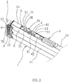
FIG. 2 is a partial perspective view of the first embodiment of the invention; -
FIG. 3 is a partial exploded view of the first embodiment of the invention; -
FIG. 4 is a top view of the first embodiment of the invention; -
FIG. 5 is a partial cross-sectional view of A-A inFIG. 4 ; -
FIG. 6 is a cross-sectional view of B-B inFIG. 4 ; -
FIG. 7 is a perspective view of a chuck in the first embodiment of the invention; -
FIG. 8 is a perspective view of a guide sleeve in the first embodiment of the invention; -
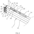
FIG. 9 is a partial perspective view of a second embodiment of the invention; -
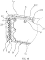
FIG. 10 is a partial perspective view of the second embodiment of the invention; -
FIG. 11 is a cross-sectional view of the second embodiment of the invention; and -
FIG. 12 is a partial exploded view of the second embodiment of the invention. - The technical solutions of the invention are further described below with reference to the specific embodiments of the invention in conjunction with the accompanied drawings, but the invention is not limited to the embodiments.
- As shown in
FIGS. 1 and2 , one embodiment of a cargo support of the invention includes across beam 1, and both ends of thecross beam 1 are respectively disposed with clamping structures with a same structure. The clamping structure includes achuck 2 disposed at one end of thecross beam 1. Thechuck 2 has aguide portion 21 and a clampingportion 22. Theguide portion 21 is elongated and disposed along an axial direction of thecross beam 1. Thecross beam 1 is of hollow structure, theguide portion 21 of thechuck 2 extends into thecross beam 1, and the clampingportion 22 is connected to one end of thecross beam 1, where the clampingportion 22 protrudes outward from thecross beam 1, and the clampingportion 22 is bent downward relative to theguide portion 21. In order to increase friction and ensure stability of clamping during a clamping process, an end face of thecross beam 1 is fixedly connected with afirst rubber cushion 1f, and the clampingportion 22 is also fixed with asecond rubber cushion 12 opposite to thefirst rubber cushion 1f. Aclamp opening 3 is formed between the clampingportion 22 and thefirst rubber cushion 1f. In addition, thecross beam 1 is further connected with ahandle 4 for driving thechuck 2 to move back and forth along the axial direction of thecross beam 1 to change a size of theclamp opening 3. - As shown in
FIG. 2 andFIG. 3 , one embodiment of thecross beam 1 is a square tube with a rectangular cross-section. Thecross beam 1 includes twolateral plates 1c disposed oppositely and parallel to each other, and a secondtop plate 1d is connected between top edges of the twolateral plates 1 c, as shown inFIG. 5 . A bottom plate 1 e is further connected between bottom edges of the twolateral plates 1c, a firsttop plate 1a located on an upper side of theguide portion 21 is provided on thecross beam 1, the firsttop plate 1a is located at an end of thecross beam 1 and is spaced apart from the secondtop plate 1d to form agap 1b. One end of thehandle 4 extends into thegap 1b and is articulated on an inner wall of thecross beam 1. Inside thecross beam 1 is further provided with a guide structure located on a lower side of the firsttop plate 1a that cooperates with theguide portion 21 and guides a movement of thechuck 2. In the clamping structure, aguide sleeve 5 matching with theguide portion 21 is also disposed inside thecross beam 1, and the firsttop plate 1a located on an upper side of theguide sleeve 5 is further disposed on thecross beam 1, thereby realizing an embedded design of theguide sleeve 5 to avoid direct exposure of matching parts between theguide sleeve 5 and theguide portion 21, so that theguide sleeve 5 is not easily interfered by external impurities and always maintains high guiding stability, ultimately ensuring more stable and smooth movement of thechuck 2, and making the cargo support stable during usage and smooth during operation. - Specifically, as shown in
FIGS. 3 to 6 , one embodiment of the guide structure is theguide sleeve 5 fixed inside thecross beam 1. Theguide sleeve 5 is made of plastic material, theguide portion 21 of thechuck 2 passes through theguide sleeve 5 and forms a sliding fit with theguide sleeve 5. Twobraces 6 located below theguide portion 21 are fixedly connected inside thecross beam 1, and the twobraces 6 are disposed at a same height and are spaced apart from each other. Preferably, the twobraces 6 are rivets. A top of theguide sleeve 5 abuts and positions on the firsttop plate 1a, a bottom of theguide sleeve 5 has fourunderpinnings 53, each of theunderpinnings 53 is provided with a through hole, one of thebraces 6 passes through the through holes on two of theunderpinnings 53, and theother brace 6 passes through the through holes on the other twounderpinnings 53. By disposing thebraces 6, theguide sleeve 5 is supported and fixed, while relying on positioning of theguide sleeve 5 by the firsttop plate 1a, theguide sleeve 5 is fixed stably, and thechuck 2 is stably guided to enable movement stability of thechuck 2. - As shown in
FIG. 6 ,FIG. 7 andFIG. 8 , one embodiment of theguide portion 21 of thechuck 2 includes two vertically disposedside guide plates 211 and anupper guide plate 212 connected between top edges of the twoside guide plates 211. Theguide sleeve 5 has a through hole penetrating through both ends, alimit portion 51 extending along a longitudinal direction of the through hole is further disposed on a bottom wall of the through hole, an upside downU-channel guide 52 matching theguide portion 21 is formed between an outer wall of thelimit portion 51 and a hole wall of the through hole, and theguide portion 21 is slidably inserted in the upside downU-channel guide 52. Such a structure enables a larger matching area between theguide sleeve 5 and theguide portion 21, thereby increasing stability and precision of guiding, and ensuring stable movement of thechuck 2. - In order to realize that one embodiment of the
handle 4 drives thechuck 2 to move, as shown inFIGS. 3 and5 , alink 7 is further provided in thecross beam 1. Thelink 7 is connected with thehandle 4 and thelink 7 is also connected with theguide portion 21 of thechuck 2, and thehandle 4 drives thechuck 2 to move through thelink 7. Specifically, thehandle 4 comprises two oppositely disposedside plates 41 and amain plate 42 connecting between top edges of the twoside plates 41, front ends of the twoside plates 41 extend into thegap 1b and are articulated on inner walls of the twolateral plates 1c of thecross beam 1 one to one. Preferably, theside plates 41 of thehandle 4 and thelateral plates 1c of thecross beam 1 are articulated by rivets. Alimiter 13 is further provided between the twoside plates 41 of thehandle 4, thelink 7 is rod-shaped, thelink 7 passes through thelimiter 13, a front end of thelink 7 is articulated with a rear end of theguide portion 21, a rear end of thelink 7 is threadly connected with anadjuster 9, and thelink 7 is further sleeved with amain spring 11 located between thelimiter 13 and theadjuster 9. The front end of thelink 7 has an articulatedball 71, anauxiliary spring 10 is further sleeved on thelink 7, thelink 7 is articulated with the rear end of theguide portion 21 through the articulatedball 71, a stiffness coefficient of theauxiliary spring 10 is less than a stiffness coefficient of themain spring 11, a first end of theauxiliary spring 10 abuts on the articulatedball 71, and a second end of theauxiliary spring 10 abuts on thelimiter 13. Since thelink 7 passes through thelimiter 13 provided on thehandle 4, when thehandle 4 is pulled upward, thechuck 2 can be driven to move forward to open theclamp opening 3. During usage, thechuck 2 in an open state attaches an object to be clamped, the object to be clamped can be a clamped part of a carriage, and then thehandle 4 is pulled downward. During pulling of thehandle 4, a size of theclamp opening 3 gradually decreases, when a size of theclamp opening 3 is reduced to equal to a thickness of the clamped part, thechuck 2 no longer moves, and thelimiter 13 is pulled to continue to move toward the rear end of thelink 7 when thehandle 4 continues to be pulled downward, resulting in themain spring 11 being compressed to form a clamping force. When thehandle 4 is lifted upward to release the load, theauxiliary spring 10 is capable of buffering the upward opening process of thehandle 4, avoiding direct impact of thehandle 4 on thecross beam 1 due to an action of themain spring 11 during upward opening process of thehandle 4, thereby avoiding damages of components or injury of operators. - The structure and principle of this embodiment are basically the same as those of the first embodiment. The differences lie in the guide structure: As shown in
FIGS. 9 and10 , the firsttop plate 1a located on the upper side of theguide portion 21 is provided on thecross beam 1, the guide structure includes the twobraces 6 fixed at ends of thecross beam 1, the twobraces 6 are both located below theguide portion 21, and the twobraces 6 are disposed at a same height and are spaced apart from each other. Aroller sleeve 8 is rotatably sleeved on each of the twobraces 6, a bottom surface of theguide portion 21 is supported on theroller sleeve 8, and a top surface of theguide portion 21 and a bottom surface of the firsttop plate 1a form a sliding fit. A sliding fit formed between the top surface of theguide portion 21 and the bottom surface of the firsttop plate 1a can be a contact or a small gap between the top surface of theguide portion 21 and the bottom surface of the firsttop plate 1a. Through such a design, theroller sleeve 8 is capable of rotating during translation process of theguide portion 21 to reduce friction, so that thechuck 2 moves smoothly and stably. - As shown in
FIG. 11 andFIG. 12 , theguide portion 21 of thechuck 2 includes the two vertically disposedside guide plates 211 and theupper guide plate 212 connecting between the top edges of the twoside guide plates 211, bottom edges of the twoside guide plates 211 are supported on theroller sleeve 8, a top surface of theupper guide plate 212 and the bottom surface of the firsttop plate 1a form a sliding fit, and a distance between outer walls of the twoside guide plates 211 is slightly smaller than a distance between the inner walls of the twolateral plates 1c of thecross beam 1. With theguide portion 21 having theupper guide plate 212, and theroller sleeve 8 locating below theupper guide plate 212 and being covered by theupper guide plate 212, external impurities are difficult to fall to reach cooperating surfaces between theroller sleeve 8 and theside guide plates 211, so that the guide structure always guides thechuck 2 stably. At the same time, in the guide structure, the firsttop plate 1a and theroller sleeve 8 cooperate to limit deviation of theguide portion 21 in upward and downward directions, and by having a distance between the outer walls of the twoside guide plates 211 slightly smaller than a distance between the inner walls of the twolateral plates 1c of thecross beam 1, deviation of theguide portion 21 in left and right directions is limited. Such a design restricts deviation of theguide portion 21 in upward and downward directions and left and right directions, thereby ensuring movement stability of thechuck 2. - The specific embodiments described herein are merely illustrative of the spirit of the invention. Technicians skilled in the art to which the invention pertains can make various modifications or additions to the specific embodiments described or replace them in a similar manner, without departing from the spirit of the invention or beyond the scope defined by the appended claims.
- Although the technical terms cross
beam 1, firsttop plate 1a,gap 1b,lateral plate 1c, secondtop plate 1d, bottom plate 1e,first rubber cushion 1f,chuck 2,guide portion 21,side guide plate 211,upper guide plate 212, clampingportion 22,clamp opening 3, handle 4,side plate 41,main plate 42,guide sleeve 5,limit portion 51, upside downU-channel guide 52, underpinning 53,brace 6,link 7, articulatedball 71,roller sleeve 8,adjuster 9,auxiliary spring 10,main spring 11,second rubber cushion 12 andlimiter 13 are used more frequently herein, the possibility of using other technical terms is not excluded. These technical terms are merely used to describe and explain the nature of the invention more conveniently; construing them as any additional limitation is contrary to the spirit of the invention. -
-
cross beam 1 - first
top plate 1a -
gap 1b -
lateral plate 1c - second
top plate 1d - bottom plate 1e
-
first rubber cushion 1f -
chuck 2 - guide
portion 21 -
side guide plate 211 -
upper guide plate 212 - clamping
portion 22 - clamp
opening 3 - handle 4
-
side plate 41 -
main plate 42 - guide
sleeve 5 -
limit portion 51 - upside down
U-channel guide 52 -
underpinning 53 -
brace 6 -
link 7 - articulated
ball 71 -
roller sleeve 8 -
adjuster 9 -
auxiliary spring 10 -
main spring 11 -
second rubber cushion 12 -
limiter 13
Claims (14)
- A clamping structure of a cargo support having a cross beam, comprising: a chuck with a guide portion and disposed at an end of the cross beam, the cross beam being connected with a handle, the handle being capable of driving the chuck to move back and forth along an axial direction of the cross beam so that the chuck switching between a clamped state and a released state, wherein the cross beam is of hollow structure, the guide portion of the chuck extends into the cross beam, and inside the cross beam is further provided with a guide structure that cooperates with the guide portion and guides a movement of the chuck.
- The clamping structure of the cargo support as claimed in claim 1, wherein a first top plate located on an upper side of the guide structure is provided on the cross beam.
- The clamping structure of the cargo support as claimed in claim 2, wherein a top of the cross beam further has a gap, a link is provided in the cross beam, one end of the handle extends into the gap and is articulated on an inner wall of the cross beam , the link is connected with the handle and the link is also connected with the guide portion of the chuck, and the handle drives the chuck to move through the link.
- The clamping structure of the cargo support as claimed in claim 1, wherein the guide structure is a guide sleeve fixed inside the cross beam, and the guide portion of the chuck passes through the guide sleeve and forms a sliding fit with the guide sleeve.
- The clamping structure of the cargo support as claimed in claim 4, wherein there is at least one brace, the at least one brace located below the guide portion is fixedly connected inside the cross beam, the cross beam is provided with a first top plate located on an upper side of the guide sleeve, a bottom of the guide sleeve is connected on the at least one brace, and a top of the guide sleeve abuts and positions on the first top plate.
- The clamping structure of the cargo support as claimed in claim 4, wherein the guide portion of the chuck includes two vertically disposed side guide plates and an upper guide plate connecting between top edges of the two side guide plates, the guide sleeve is made of plastic material, the guide sleeve has a through hole penetrating through both ends, a limit portion extending along a longitudinal direction of the through hole is further disposed on a bottom wall of the through hole, an upside down U-channel guide matching the guide portion is formed between an outer wall of the limit portion and a hole wall of the through hole, and the guide portion is slidably inserted in the upside down U-channel guide.
- The clamping structure of the cargo support as claimed in claim 6, wherein there are two braces, the two braces are disposed at a same height and are spaced apart from each other, the bottom of the guide sleeve is provided with underpinnings at positions corresponding to each of the two braces, and the underpinnings are respectively sleeved on corresponding braces.
- The clamping structure of the cargo support as claimed in claim 3, wherein the cross beam is a square tube with a rectangular cross section, the cross beam comprises two lateral plates disposed oppositely and parallel to each other, a second top plate is connected between top edges of the two lateral plates, and the first top plate is located at an end of the cross beam and is spaced apart from the second top plate to form the gap.
- The clamping structure of the cargo support as claimed in claim 8, wherein the handle comprises two oppositely disposed side plates and a main plate connecting between top edges of the two side plates, front ends of the two side plates extend into the gap and are articulated on inner walls of the two lateral plates of the cross beam one to one.
- The clamping structure of the cargo support as claimed in claim 1, wherein the cross beam is provided with a first top plate located on an upper side of the guide portion, the guide structure comprises at least one brace fixed inside the cross beam, the at least one brace is located below the guide portion, a roller sleeve is rotatably sleeved on the at least one brace, a bottom surface of the guide portion is supported on the roller sleeve, and a top surface of the guide portion and a bottom surface of the first top plate form a sliding fit.
- The clamping structure of the cargo support as claimed in claim 10, wherein there are two braces, each of the two braces is provided with the roller sleeve, and the two braces are disposed at a same height and are spaced apart from each other.
- The clamping structure of the cargo support as claimed in claim 10, wherein the cross beam is a square tube with a rectangular cross section, the cross beam comprises two lateral plates disposed oppositely and parallel to each other, the guide portion of the chuck includes two vertically disposed side guide plates and an upper guide plate connecting between top edges of the two side guide plates, bottom edges of the two side guide plates are supported on the roller sleeve, a top surface of the upper guide plate and the bottom surface of the first top plate form a sliding fit, and a distance between outer walls of the two side guide plates is slightly smaller than a distance between inner walls of the two lateral plates of the cross beam.
- The clamping structure of the cargo support as claimed in claim 9, wherein a limiter is further provided between the two side plates of the handle, the link is rod-shaped, the link passes through the limiter, a front end of the link is articulated with a rear end of the guide portion, a rear end of the link is threadly connected with an adjuster, and the link is further sleeved with a main spring located between the limiter and the adjuster.
- The clamping structure of the cargo support as claimed in claim 13, wherein the front end of the link has an articulated ball, an auxiliary spring is further sleeved on the link, the link is articulated with the rear end of the guide portion through the articulated ball, a stiffness coefficient of the auxiliary spring is less than a stiffness coefficient of the main spring, a first end of the auxiliary spring abuts on the articulated ball, and a second end of the auxiliary spring abuts on the limiter.
Applications Claiming Priority (1)
| Application Number | Priority Date | Filing Date | Title |
|---|---|---|---|
| CN202010395252.4A CN111619436B (en) | 2020-05-12 | 2020-05-12 | Clamping structure of cargo support |
Publications (2)
| Publication Number | Publication Date |
|---|---|
| EP3909810A1 true EP3909810A1 (en) | 2021-11-17 |
| EP3909810B1 EP3909810B1 (en) | 2023-03-29 |
Family
ID=72267978
Family Applications (1)
| Application Number | Title | Priority Date | Filing Date |
|---|---|---|---|
| EP20203439.3A Active EP3909810B1 (en) | 2020-05-12 | 2020-10-22 | Clamping structure of cargo support |
Country Status (3)
| Country | Link |
|---|---|
| EP (1) | EP3909810B1 (en) |
| CN (1) | CN111619436B (en) |
| ES (1) | ES2945859T3 (en) |
Cited By (2)
| Publication number | Priority date | Publication date | Assignee | Title |
|---|---|---|---|---|
| CN117325924A (en) * | 2023-11-10 | 2024-01-02 | 河北君业科技股份有限公司 | A kind of in-plant transfer device for prefabricated insulated pipes |
| EP4711202A1 (en) * | 2024-09-10 | 2026-03-18 | Pwp Sa | Locking beam for securing loads |
Citations (2)
| Publication number | Priority date | Publication date | Assignee | Title |
|---|---|---|---|---|
| CN1970340A (en) * | 2006-12-06 | 2007-05-30 | 浙江双友机电集团股份有限公司 | F-shaped nip and manufacturing method thereof |
| DE102009033320A1 (en) * | 2009-07-15 | 2011-02-24 | Manfred Berger | Intermediate wall closure for protecting loading components in loading chamber, particularly in motor vehicle-superstructures or freight containers, has intermediate wall closure body, which extends along longitudinal direction |
Family Cites Families (4)
| Publication number | Priority date | Publication date | Assignee | Title |
|---|---|---|---|---|
| DE3422970C2 (en) * | 1984-06-22 | 1986-04-30 | TS Gesellschaft für Transport- und Sicherungssysteme mbH, 5600 Wuppertal | Device for quick-release clamping of a room divider to partition walls |
| DE9204539U1 (en) * | 1992-04-02 | 1992-06-17 | F. Hesterberg & Söhne GmbH & Co KG, 5828 Ennepetal | Load securing device that can be clamped to opposite side walls of trucks |
| DE20012731U1 (en) * | 1999-12-13 | 2000-12-14 | ANCRA Jungfalk GmbH & Co. KG, 78234 Engen | Device for securing cargo on the loading surface of a vehicle |
| US7410335B2 (en) * | 2004-09-07 | 2008-08-12 | Burns Bros., Inc. | Cargo stabilizing structures |
-
2020
- 2020-05-12 CN CN202010395252.4A patent/CN111619436B/en active Active
- 2020-10-22 EP EP20203439.3A patent/EP3909810B1/en active Active
- 2020-10-22 ES ES20203439T patent/ES2945859T3/en active Active
Patent Citations (3)
| Publication number | Priority date | Publication date | Assignee | Title |
|---|---|---|---|---|
| CN1970340A (en) * | 2006-12-06 | 2007-05-30 | 浙江双友机电集团股份有限公司 | F-shaped nip and manufacturing method thereof |
| CN1970340B (en) | 2006-12-06 | 2011-06-01 | 浙江双友物流器械股份有限公司 | F-shaped cargo clip and manufacturing method thereof |
| DE102009033320A1 (en) * | 2009-07-15 | 2011-02-24 | Manfred Berger | Intermediate wall closure for protecting loading components in loading chamber, particularly in motor vehicle-superstructures or freight containers, has intermediate wall closure body, which extends along longitudinal direction |
Cited By (2)
| Publication number | Priority date | Publication date | Assignee | Title |
|---|---|---|---|---|
| CN117325924A (en) * | 2023-11-10 | 2024-01-02 | 河北君业科技股份有限公司 | A kind of in-plant transfer device for prefabricated insulated pipes |
| EP4711202A1 (en) * | 2024-09-10 | 2026-03-18 | Pwp Sa | Locking beam for securing loads |
Also Published As
| Publication number | Publication date |
|---|---|
| CN111619436B (en) | 2021-11-19 |
| ES2945859T3 (en) | 2023-07-10 |
| CN111619436A (en) | 2020-09-04 |
| EP3909810B1 (en) | 2023-03-29 |
Similar Documents
| Publication | Publication Date | Title |
|---|---|---|
| EP3292788B1 (en) | Slide rail assembly | |
| US10213017B2 (en) | Slide rail assembly | |
| EP3909810A1 (en) | Clamping structure of cargo support | |
| US9992906B2 (en) | Slide rail assembly and operation method thereof | |
| JP6721565B2 (en) | Slide rail assembly | |
| US8430567B2 (en) | Load adaptive roller carriage assembly | |
| US10918209B1 (en) | Slide rail assembly | |
| US10674820B2 (en) | Slide rail assembly and driving mechanism thereof | |
| KR101823063B1 (en) | Bidirectional drawer-type loading device for heavy weights with double stopper structure | |
| US7490643B2 (en) | Worktable having slidable board | |
| EP3808215B1 (en) | Slide rail assembly | |
| EP3821761B1 (en) | Slide rail assembly | |
| EP3821762B1 (en) | Slide rail assembly | |
| US20120160793A1 (en) | Storage rack | |
| US7178889B2 (en) | Slide rail | |
| US20130136568A1 (en) | Handling mechanism | |
| CN107951237B (en) | Sliding rail assembly | |
| EP4159086B1 (en) | Slide rail assembly | |
| US6631586B1 (en) | Opening and closing structure of window member | |
| CN212608954U (en) | Single-double door of elevator and door handle box thereof | |
| KR101654918B1 (en) | Lower roller bracket of sliding door | |
| CN112386025B (en) | Sliding rail assembly | |
| KR102221573B1 (en) | Door schassis including push frame and guide piece for separation prevention | |
| CN210539962U (en) | Drawer adjusting device and drawer assembly | |
| JP5983643B2 (en) | Apron mounting jig |
Legal Events
| Date | Code | Title | Description |
|---|---|---|---|
| PUAI | Public reference made under article 153(3) epc to a published international application that has entered the european phase |
Free format text: ORIGINAL CODE: 0009012 |
|
| STAA | Information on the status of an ep patent application or granted ep patent |
Free format text: STATUS: REQUEST FOR EXAMINATION WAS MADE |
|
| 17P | Request for examination filed |
Effective date: 20201022 |
|
| AK | Designated contracting states |
Kind code of ref document: A1 Designated state(s): AL AT BE BG CH CY CZ DE DK EE ES FI FR GB GR HR HU IE IS IT LI LT LU LV MC MK MT NL NO PL PT RO RS SE SI SK SM TR |
|
| B565 | Issuance of search results under rule 164(2) epc |
Effective date: 20210331 |
|
| GRAP | Despatch of communication of intention to grant a patent |
Free format text: ORIGINAL CODE: EPIDOSNIGR1 |
|
| STAA | Information on the status of an ep patent application or granted ep patent |
Free format text: STATUS: GRANT OF PATENT IS INTENDED |
|
| INTG | Intention to grant announced |
Effective date: 20221020 |
|
| GRAS | Grant fee paid |
Free format text: ORIGINAL CODE: EPIDOSNIGR3 |
|
| GRAA | (expected) grant |
Free format text: ORIGINAL CODE: 0009210 |
|
| STAA | Information on the status of an ep patent application or granted ep patent |
Free format text: STATUS: THE PATENT HAS BEEN GRANTED |
|
| AK | Designated contracting states |
Kind code of ref document: B1 Designated state(s): AL AT BE BG CH CY CZ DE DK EE ES FI FR GB GR HR HU IE IS IT LI LT LU LV MC MK MT NL NO PL PT RO RS SE SI SK SM TR |
|
| REG | Reference to a national code |
Ref country code: CH Ref legal event code: EP |
|
| REG | Reference to a national code |
Ref country code: DE Ref legal event code: R096 Ref document number: 602020009195 Country of ref document: DE |
|
| REG | Reference to a national code |
Ref country code: AT Ref legal event code: REF Ref document number: 1556458 Country of ref document: AT Kind code of ref document: T Effective date: 20230415 |
|
| REG | Reference to a national code |
Ref country code: IE Ref legal event code: FG4D |
|
| REG | Reference to a national code |
Ref country code: LT Ref legal event code: MG9D Ref country code: ES Ref legal event code: FG2A Ref document number: 2945859 Country of ref document: ES Kind code of ref document: T3 Effective date: 20230710 |
|
| PG25 | Lapsed in a contracting state [announced via postgrant information from national office to epo] |
Ref country code: RS Free format text: LAPSE BECAUSE OF FAILURE TO SUBMIT A TRANSLATION OF THE DESCRIPTION OR TO PAY THE FEE WITHIN THE PRESCRIBED TIME-LIMIT Effective date: 20230329 Ref country code: NO Free format text: LAPSE BECAUSE OF FAILURE TO SUBMIT A TRANSLATION OF THE DESCRIPTION OR TO PAY THE FEE WITHIN THE PRESCRIBED TIME-LIMIT Effective date: 20230629 Ref country code: LV Free format text: LAPSE BECAUSE OF FAILURE TO SUBMIT A TRANSLATION OF THE DESCRIPTION OR TO PAY THE FEE WITHIN THE PRESCRIBED TIME-LIMIT Effective date: 20230329 Ref country code: LT Free format text: LAPSE BECAUSE OF FAILURE TO SUBMIT A TRANSLATION OF THE DESCRIPTION OR TO PAY THE FEE WITHIN THE PRESCRIBED TIME-LIMIT Effective date: 20230329 Ref country code: HR Free format text: LAPSE BECAUSE OF FAILURE TO SUBMIT A TRANSLATION OF THE DESCRIPTION OR TO PAY THE FEE WITHIN THE PRESCRIBED TIME-LIMIT Effective date: 20230329 |
|
| REG | Reference to a national code |
Ref country code: NL Ref legal event code: MP Effective date: 20230329 |
|
| REG | Reference to a national code |
Ref country code: AT Ref legal event code: MK05 Ref document number: 1556458 Country of ref document: AT Kind code of ref document: T Effective date: 20230329 |
|
| PG25 | Lapsed in a contracting state [announced via postgrant information from national office to epo] |
Ref country code: SE Free format text: LAPSE BECAUSE OF FAILURE TO SUBMIT A TRANSLATION OF THE DESCRIPTION OR TO PAY THE FEE WITHIN THE PRESCRIBED TIME-LIMIT Effective date: 20230329 Ref country code: NL Free format text: LAPSE BECAUSE OF FAILURE TO SUBMIT A TRANSLATION OF THE DESCRIPTION OR TO PAY THE FEE WITHIN THE PRESCRIBED TIME-LIMIT Effective date: 20230329 Ref country code: GR Free format text: LAPSE BECAUSE OF FAILURE TO SUBMIT A TRANSLATION OF THE DESCRIPTION OR TO PAY THE FEE WITHIN THE PRESCRIBED TIME-LIMIT Effective date: 20230630 Ref country code: FI Free format text: LAPSE BECAUSE OF FAILURE TO SUBMIT A TRANSLATION OF THE DESCRIPTION OR TO PAY THE FEE WITHIN THE PRESCRIBED TIME-LIMIT Effective date: 20230329 |
|
| PG25 | Lapsed in a contracting state [announced via postgrant information from national office to epo] |
Ref country code: SM Free format text: LAPSE BECAUSE OF FAILURE TO SUBMIT A TRANSLATION OF THE DESCRIPTION OR TO PAY THE FEE WITHIN THE PRESCRIBED TIME-LIMIT Effective date: 20230329 Ref country code: RO Free format text: LAPSE BECAUSE OF FAILURE TO SUBMIT A TRANSLATION OF THE DESCRIPTION OR TO PAY THE FEE WITHIN THE PRESCRIBED TIME-LIMIT Effective date: 20230329 Ref country code: PT Free format text: LAPSE BECAUSE OF FAILURE TO SUBMIT A TRANSLATION OF THE DESCRIPTION OR TO PAY THE FEE WITHIN THE PRESCRIBED TIME-LIMIT Effective date: 20230731 Ref country code: EE Free format text: LAPSE BECAUSE OF FAILURE TO SUBMIT A TRANSLATION OF THE DESCRIPTION OR TO PAY THE FEE WITHIN THE PRESCRIBED TIME-LIMIT Effective date: 20230329 Ref country code: AT Free format text: LAPSE BECAUSE OF FAILURE TO SUBMIT A TRANSLATION OF THE DESCRIPTION OR TO PAY THE FEE WITHIN THE PRESCRIBED TIME-LIMIT Effective date: 20230329 |
|
| PG25 | Lapsed in a contracting state [announced via postgrant information from national office to epo] |
Ref country code: SK Free format text: LAPSE BECAUSE OF FAILURE TO SUBMIT A TRANSLATION OF THE DESCRIPTION OR TO PAY THE FEE WITHIN THE PRESCRIBED TIME-LIMIT Effective date: 20230329 Ref country code: PL Free format text: LAPSE BECAUSE OF FAILURE TO SUBMIT A TRANSLATION OF THE DESCRIPTION OR TO PAY THE FEE WITHIN THE PRESCRIBED TIME-LIMIT Effective date: 20230329 Ref country code: IS Free format text: LAPSE BECAUSE OF FAILURE TO SUBMIT A TRANSLATION OF THE DESCRIPTION OR TO PAY THE FEE WITHIN THE PRESCRIBED TIME-LIMIT Effective date: 20230729 |
|
| REG | Reference to a national code |
Ref country code: DE Ref legal event code: R097 Ref document number: 602020009195 Country of ref document: DE |
|
| PG25 | Lapsed in a contracting state [announced via postgrant information from national office to epo] |
Ref country code: DK Free format text: LAPSE BECAUSE OF FAILURE TO SUBMIT A TRANSLATION OF THE DESCRIPTION OR TO PAY THE FEE WITHIN THE PRESCRIBED TIME-LIMIT Effective date: 20230329 Ref country code: CZ Free format text: LAPSE BECAUSE OF FAILURE TO SUBMIT A TRANSLATION OF THE DESCRIPTION OR TO PAY THE FEE WITHIN THE PRESCRIBED TIME-LIMIT Effective date: 20230329 |
|
| PLBE | No opposition filed within time limit |
Free format text: ORIGINAL CODE: 0009261 |
|
| STAA | Information on the status of an ep patent application or granted ep patent |
Free format text: STATUS: NO OPPOSITION FILED WITHIN TIME LIMIT |
|
| 26N | No opposition filed |
Effective date: 20240103 |
|
| PG25 | Lapsed in a contracting state [announced via postgrant information from national office to epo] |
Ref country code: SI Free format text: LAPSE BECAUSE OF FAILURE TO SUBMIT A TRANSLATION OF THE DESCRIPTION OR TO PAY THE FEE WITHIN THE PRESCRIBED TIME-LIMIT Effective date: 20230329 |
|
| PG25 | Lapsed in a contracting state [announced via postgrant information from national office to epo] |
Ref country code: SI Free format text: LAPSE BECAUSE OF FAILURE TO SUBMIT A TRANSLATION OF THE DESCRIPTION OR TO PAY THE FEE WITHIN THE PRESCRIBED TIME-LIMIT Effective date: 20230329 Ref country code: MC Free format text: LAPSE BECAUSE OF FAILURE TO SUBMIT A TRANSLATION OF THE DESCRIPTION OR TO PAY THE FEE WITHIN THE PRESCRIBED TIME-LIMIT Effective date: 20230329 |
|
| REG | Reference to a national code |
Ref country code: CH Ref legal event code: PL |
|
| REG | Reference to a national code |
Ref country code: BE Ref legal event code: MM Effective date: 20231031 |
|
| PG25 | Lapsed in a contracting state [announced via postgrant information from national office to epo] |
Ref country code: LU Free format text: LAPSE BECAUSE OF NON-PAYMENT OF DUE FEES Effective date: 20231022 |
|
| PG25 | Lapsed in a contracting state [announced via postgrant information from national office to epo] |
Ref country code: LU Free format text: LAPSE BECAUSE OF NON-PAYMENT OF DUE FEES Effective date: 20231022 |
|
| PG25 | Lapsed in a contracting state [announced via postgrant information from national office to epo] |
Ref country code: CH Free format text: LAPSE BECAUSE OF NON-PAYMENT OF DUE FEES Effective date: 20231031 |
|
| PG25 | Lapsed in a contracting state [announced via postgrant information from national office to epo] |
Ref country code: CH Free format text: LAPSE BECAUSE OF NON-PAYMENT OF DUE FEES Effective date: 20231031 |
|
| PG25 | Lapsed in a contracting state [announced via postgrant information from national office to epo] |
Ref country code: BE Free format text: LAPSE BECAUSE OF NON-PAYMENT OF DUE FEES Effective date: 20231031 |
|
| PG25 | Lapsed in a contracting state [announced via postgrant information from national office to epo] |
Ref country code: IE Free format text: LAPSE BECAUSE OF NON-PAYMENT OF DUE FEES Effective date: 20231022 |
|
| PG25 | Lapsed in a contracting state [announced via postgrant information from national office to epo] |
Ref country code: IE Free format text: LAPSE BECAUSE OF NON-PAYMENT OF DUE FEES Effective date: 20231022 |
|
| PG25 | Lapsed in a contracting state [announced via postgrant information from national office to epo] |
Ref country code: BG Free format text: LAPSE BECAUSE OF FAILURE TO SUBMIT A TRANSLATION OF THE DESCRIPTION OR TO PAY THE FEE WITHIN THE PRESCRIBED TIME-LIMIT Effective date: 20230329 |
|
| PG25 | Lapsed in a contracting state [announced via postgrant information from national office to epo] |
Ref country code: BG Free format text: LAPSE BECAUSE OF FAILURE TO SUBMIT A TRANSLATION OF THE DESCRIPTION OR TO PAY THE FEE WITHIN THE PRESCRIBED TIME-LIMIT Effective date: 20230329 |
|
| GBPC | Gb: european patent ceased through non-payment of renewal fee |
Effective date: 20241022 |
|
| PG25 | Lapsed in a contracting state [announced via postgrant information from national office to epo] |
Ref country code: GB Free format text: LAPSE BECAUSE OF NON-PAYMENT OF DUE FEES Effective date: 20241022 |
|
| PG25 | Lapsed in a contracting state [announced via postgrant information from national office to epo] |
Ref country code: CY Free format text: LAPSE BECAUSE OF FAILURE TO SUBMIT A TRANSLATION OF THE DESCRIPTION OR TO PAY THE FEE WITHIN THE PRESCRIBED TIME-LIMIT; INVALID AB INITIO Effective date: 20201022 |
|
| PG25 | Lapsed in a contracting state [announced via postgrant information from national office to epo] |
Ref country code: HU Free format text: LAPSE BECAUSE OF FAILURE TO SUBMIT A TRANSLATION OF THE DESCRIPTION OR TO PAY THE FEE WITHIN THE PRESCRIBED TIME-LIMIT; INVALID AB INITIO Effective date: 20201022 |
|
| PG25 | Lapsed in a contracting state [announced via postgrant information from national office to epo] |
Ref country code: TR Free format text: LAPSE BECAUSE OF FAILURE TO SUBMIT A TRANSLATION OF THE DESCRIPTION OR TO PAY THE FEE WITHIN THE PRESCRIBED TIME-LIMIT Effective date: 20230329 |
|
| PGFP | Annual fee paid to national office [announced via postgrant information from national office to epo] |
Ref country code: DE Payment date: 20251021 Year of fee payment: 6 |
|
| PGFP | Annual fee paid to national office [announced via postgrant information from national office to epo] |
Ref country code: IT Payment date: 20251024 Year of fee payment: 6 |
|
| PGFP | Annual fee paid to national office [announced via postgrant information from national office to epo] |
Ref country code: FR Payment date: 20251030 Year of fee payment: 6 |
|
| PGFP | Annual fee paid to national office [announced via postgrant information from national office to epo] |
Ref country code: ES Payment date: 20251111 Year of fee payment: 6 |