EP3909784A1 - An anti-loosening device for a fastening unit of a motor-vehicle wheel - Google Patents
An anti-loosening device for a fastening unit of a motor-vehicle wheel Download PDFInfo
- Publication number
- EP3909784A1 EP3909784A1 EP20174331.7A EP20174331A EP3909784A1 EP 3909784 A1 EP3909784 A1 EP 3909784A1 EP 20174331 A EP20174331 A EP 20174331A EP 3909784 A1 EP3909784 A1 EP 3909784A1
- Authority
- EP
- European Patent Office
- Prior art keywords
- wheel
- wheel hub
- gear
- loosening device
- hub
- Prior art date
- Legal status (The legal status is an assumption and is not a legal conclusion. Google has not performed a legal analysis and makes no representation as to the accuracy of the status listed.)
- Granted
Links
- 230000008878 coupling Effects 0.000 claims abstract description 40
- 238000010168 coupling process Methods 0.000 claims abstract description 40
- 238000005859 coupling reaction Methods 0.000 claims abstract description 40
- 238000000034 method Methods 0.000 claims description 10
- 238000003825 pressing Methods 0.000 claims description 3
- 230000008595 infiltration Effects 0.000 claims description 2
- 238000001764 infiltration Methods 0.000 claims description 2
- XLYOFNOQVPJJNP-UHFFFAOYSA-N water Substances O XLYOFNOQVPJJNP-UHFFFAOYSA-N 0.000 claims description 2
- 230000000694 effects Effects 0.000 description 3
- 239000000463 material Substances 0.000 description 3
- 238000010276 construction Methods 0.000 description 2
- 230000008030 elimination Effects 0.000 description 2
- 238000003379 elimination reaction Methods 0.000 description 2
- 230000009467 reduction Effects 0.000 description 2
- 239000000725 suspension Substances 0.000 description 2
- RTAQQCXQSZGOHL-UHFFFAOYSA-N Titanium Chemical compound [Ti] RTAQQCXQSZGOHL-UHFFFAOYSA-N 0.000 description 1
- 230000009471 action Effects 0.000 description 1
- 238000004026 adhesive bonding Methods 0.000 description 1
- 230000008859 change Effects 0.000 description 1
- 229910052719 titanium Inorganic materials 0.000 description 1
- 239000010936 titanium Substances 0.000 description 1
Images


Classifications
-
- B—PERFORMING OPERATIONS; TRANSPORTING
- B60—VEHICLES IN GENERAL
- B60B—VEHICLE WHEELS; CASTORS; AXLES FOR WHEELS OR CASTORS; INCREASING WHEEL ADHESION
- B60B3/00—Disc wheels, i.e. wheels with load-supporting disc body
- B60B3/14—Attaching disc body to hub ; Wheel adapters
- B60B3/142—Attaching disc body to hub ; Wheel adapters by central locking nut
-
- B—PERFORMING OPERATIONS; TRANSPORTING
- B60—VEHICLES IN GENERAL
- B60B—VEHICLE WHEELS; CASTORS; AXLES FOR WHEELS OR CASTORS; INCREASING WHEEL ADHESION
- B60B30/00—Means for holding wheels or parts thereof
-
- B—PERFORMING OPERATIONS; TRANSPORTING
- B60—VEHICLES IN GENERAL
- B60B—VEHICLE WHEELS; CASTORS; AXLES FOR WHEELS OR CASTORS; INCREASING WHEEL ADHESION
- B60B3/00—Disc wheels, i.e. wheels with load-supporting disc body
- B60B3/14—Attaching disc body to hub ; Wheel adapters
- B60B3/16—Attaching disc body to hub ; Wheel adapters by bolts or the like
- B60B3/165—Attaching disc body to hub ; Wheel adapters by bolts or the like with locking devices for the fixing means, e.g. screw or nut covers
-
- F—MECHANICAL ENGINEERING; LIGHTING; HEATING; WEAPONS; BLASTING
- F16—ENGINEERING ELEMENTS AND UNITS; GENERAL MEASURES FOR PRODUCING AND MAINTAINING EFFECTIVE FUNCTIONING OF MACHINES OR INSTALLATIONS; THERMAL INSULATION IN GENERAL
- F16B—DEVICES FOR FASTENING OR SECURING CONSTRUCTIONAL ELEMENTS OR MACHINE PARTS TOGETHER, e.g. NAILS, BOLTS, CIRCLIPS, CLAMPS, CLIPS OR WEDGES; JOINTS OR JOINTING
- F16B39/00—Locking of screws, bolts or nuts
- F16B39/02—Locking of screws, bolts or nuts in which the locking takes place after screwing down
- F16B39/10—Locking of screws, bolts or nuts in which the locking takes place after screwing down by a plate, spring, wire or ring immovable with regard to the bolt or object and mainly perpendicular to the axis of the bolt
-
- F—MECHANICAL ENGINEERING; LIGHTING; HEATING; WEAPONS; BLASTING
- F16—ENGINEERING ELEMENTS AND UNITS; GENERAL MEASURES FOR PRODUCING AND MAINTAINING EFFECTIVE FUNCTIONING OF MACHINES OR INSTALLATIONS; THERMAL INSULATION IN GENERAL
- F16B—DEVICES FOR FASTENING OR SECURING CONSTRUCTIONAL ELEMENTS OR MACHINE PARTS TOGETHER, e.g. NAILS, BOLTS, CIRCLIPS, CLAMPS, CLIPS OR WEDGES; JOINTS OR JOINTING
- F16B39/00—Locking of screws, bolts or nuts
- F16B39/02—Locking of screws, bolts or nuts in which the locking takes place after screwing down
- F16B39/04—Locking of screws, bolts or nuts in which the locking takes place after screwing down with a member penetrating the screw-threaded surface of at least one part, e.g. a pin, a wedge, cotter-pin, screw
- F16B39/06—Locking of screws, bolts or nuts in which the locking takes place after screwing down with a member penetrating the screw-threaded surface of at least one part, e.g. a pin, a wedge, cotter-pin, screw with a pin or staple parallel to the bolt axis
Definitions
- the present invention relates to an anti-loosening device for a fastening unit of a motor-vehicle wheel, wherein the motor-vehicle wheel is configured to be coupled to a wheel hub by means of said fastening unit.
- the present invention starts from the desire to provide an anti-loosening device for a motor-vehicle wheel assembly comprising a single-nut fastening unit, and a related assembly method of the wheel assembly, which is particularly effective in preventing loosening or over-tightening of the fastening unit during operation, caused, for example, by the effect of the driving torque and the braking torque.
- the object of the present invention is to provide an anti-loosening device for a fastening unit of a motor-vehicle wheel that meets the above requirements.
- Another object of the invention is to provide an anti-loosening device that lends itself to be easily implemented, in order to minimize the anomalies resulting from loosening or over-tightening the locking unit.
- An additional object of the invention is to provide a simple, low-cost device that is uniquely usable for wheels and hubs arranged on both sides of a motor-vehicle.
- Another object of the invention is to propose an assembly method for assembling a motor-vehicle wheel assembly including a device of the type indicated above, which is particularly simple.
- the invention relates to an anti-loosening device for a fastening unit of a motor-vehicle wheel, wherein the motor-vehicle wheel is configured to be coupled with a wheel hub by means of said fastening unit, said anti-loosening device comprising:
- the present invention also relates to a motor-vehicle wheel assembly including the aforesaid device, and relative assembly method.
- reference 1 generally indicates a preferred embodiment of an anti-loosening device for a fastening unit of a motor-vehicle wheel according to the present invention.
- Figure 1 is an exploded perspective view of a motor-vehicle wheel assembly including the device 1 according to the invention, Figure 1 - according to a technique known per se - shows a wheel hub structure U and a motor-vehicle wheel W arranged to be connected to the hub structure U. It is noted that the construction details relating to the tire of the wheel W are not presented here, since these details can be made in any known way, and also since elimination of these details from the drawings makes the latter more readily and easily understood.
- the wheel hub structure U comprises:
- the reference D1 indicates a circumferential series of centering members, arranged protruding from the brake disc D along a direction parallel to the main axis of the hub H. As indicated in greater detail in the description that follows, these centering members D1 are designed to be selectively arranged within respective seats W1 obtained on the body of the wheel W, so as to achieve centering of the wheel W on the hub H.
- the term "centering" means the correct angular positioning of the wheel W with respect to the hub H during assembly of the wheel W on the hub H, so as to transmit the driving torque and the braking torque.
- the centering of the wheel W is carried out with the aid of a single centering member.
- the present invention is also applicable to the case in which these centering elements are not provided, since the transfer of the torque is carried out solely by means of the friction between the wheel and the hub without the use of driving devices.
- the wheel hub H comprises an end thread H1 arranged for reciprocal coupling with a single-nut fastening unit 2 arranged to lock the wheel W on the hub H, once centering has occurred with respect to the latter. Greater details relative to this fastening unit 2 are indicated below in the present description.
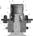
- Figure 2 illustrates an enlarged cross-sectional view of the wheel hub structure U shown in the previous figure.
- the unit U is configured to receive a wheel pin P therein.
- the wheel pin P can be connected in rotation with a respective axle shaft (not illustrated in the drawings) by means of an articulated homokinetic joint, so as to form a traction wheel assembly.
- the details relating to the connection of the axle shaft with the differential gear of the motor-vehicle, as well as those relating to the suspension of this wheel W are not illustrated here, as they can be made in any known way, and as these details taken alone, do not fall within the scope of the present invention.
- the invention can be applied to both drive wheels and non-drive wheels.
- the anti-loosening device 1 comprises a gear 3 and an elastic element 5 extending axially with respect to the gear 3.
- the gear 3 has outer teeth 4 arranged to cooperate, in an assembled condition of the wheel assembly, with inner teeth H3 of the wheel hub H, obtained at an end portion H4 of the hub H, along an inner surface H2 thereof. More particularly, the inner teeth H3 are arranged on the end edge of the hub H.
- Figure 3 is a cross-sectional view that illustrates the wheel W centered on the wheel hub H. As indicated above, in this condition, the centering members D1 are arranged within respective seats W1 obtained on the body of the wheel W.
- a tool may be used (not illustrated in the drawings) incorporating the technical disclosures deriving from the patent application EP 20165839.0 in the name of the same Applicant, forming part of the state-of-the-art pursuant to Art. 54(3) EPC.
- the tool has a tubular body defining a coupling portion arranged for coupling to the wheel hub H, and a carrier portion for supporting the motor-vehicle wheel W during a centering step of the wheel W on the hub H.
- the centering of the wheel W on the wheel hub H can be carried out, in the case of the present invention, even without the aid of this tool.
- Figure 4 shows an enlarged cross-sectional view of the wheel W centered on the hub H, with the anti-loosening device 1 coupled to the wheel hub H.
- the anti-loosening device 1 is configured to be inserted within the wheel hub H along an axial direction, so that the main axis of the anti-loosening device 1 coincides with the wheel-hub axis.
- the outer teeth 4 of the gear 3 are configured to engage the inner teeth H3 of the wheel hub H.
- the elastic element 5 is spaced along an axial direction with respect to the gear 3, in the direction of the wheel pin P protruding into the hub H from the side of the wheel upright M opposite the end of the hub H cooperating with the gear 3.
- the elastic element 5 is a conical helical spring with a progressively smaller diameter along a direction moving away from the gear 3.
- the elastic element 5 comprises a first end 6 connected to the gear 3 and a second end 7 configured to be engaged against at least one abutment and centering surface obtained inside the hub H.
- this abutment and centering surface is defined by a wheel pin P extending within the hub H on the opposite side with respect to the inner teeth H3 ( Figure 4 ).
- the first end 6 can be integrated directly into the body of the gear 3, while the second end 7 can be fitted onto the end of the wheel pin P, so that said second end 7 is supported by the wheel pin P, and is in abutment against an end portion of the wheel pin P.
- the gear 3 has an annular conformation in that it includes a central hole 11 formed to allow drainage of water infiltrations possibly passing inside the assembled wheel assembly.
- the central hole 11 is also designed to reduce the overall weight of the device 1, and to achieve the centering of a socket for screwing during assembly.
- the anti-loosening device 1 further comprises a coupling element 8 obtained on a sector of the gear 3, along a direction substantially parallel to an axial direction of the gear 3.
- the coupling element 8 is arranged to receive a corresponding fastening member 10 (illustrated in Figure 1 ).
- the coupling element 8 is a threaded nut arranged to receive a corresponding threaded fastening screw 10.
- Figure 5 is a front perspective view of the components illustrated in Figure 4 , wherein the wheel W is centered on the hub H, with the anti-loosening device 1 coupled to the wheel hub H. In this condition, the wheel W is not yet locked onto the hub H, since the fastening unit 2 must still be applied onto the wheel-hub assembly.
- the wheel W has a series of recessed portions 12 ( Figure 1 ) arranged side by side on its inner circumferential wall. As illustrated in the assembled configuration of Figure 5 , wherein the wheel is centered on the hub H and arranged against the brake disc D, some portions of the brake disc D remain visible from an observation direction corresponding to that illustrated in Figure 5 due to the aforesaid recessed portions 12.
- These recessed portions 12 are arranged to limit the contact between the wheel W and hub H during centering of the wheel, and to reduce the gluing effect by galvanic effect.
- the recessed portions 12 also allow reduction of the overall weight of the wheel assembly, and elimination of any humidity present inside.
- the single-nut fastening unit 2 is applied onto the wheel hub H.
- the fastening unit 2 is defined by a single coupling nut having an inner thread 13 arranged to engage with the end thread H1 of the wheel hub H.
- the single-nut fastening unit 2 also comprises an outer portion with grooves 14 so as to facilitate gripping of the unit 2.
- the single-nut unit 2 also has a central hole 15, so that in the assembled condition of the wheel assembly, a part of the outer surface of the gear 3 is visible from the outside, despite the engagement of said single-nut fastening unit 2 on said wheel hub H.
- this characteristic is particularly relevant to allow an action on the device 1 despite the presence of the single-nut unit 2, as well as allowing the application of any friezes and/or marks.
- the single-nut unit 2 has at least one anti-rotation sector 9 (also illustrated in Figure 1 ), arranged at a portion of its inner circumferential wall defined by the central hole 15.
- the anti-rotation sector 9 is defined by a cavity portion obtained along a sector of its inner circumferential wall.
- the anti-rotation sector 9 is configured to cooperate with the fastening member 10 engaged with the coupling element 8 obtained on the gear 3.
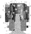
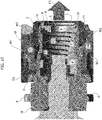
- FIG. 6 is a cross-sectional view that illustrates the wheel assembly including the anti-loosening device 1, with the single-nut fastening unit 2 tightened on the hub H.
- the wheel W has a recess portion W2 arranged to receive the single-nut unit 2 screwed on the hub H.
- the inner thread 13 of the unit 2 is engaged with the thread H1 of the wheel hub H, in such a way that the wheel W is blocked on the hub H.
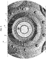
- Figure 7 is a front view of the wheel assembly with its components assembled in the configuration illustrated in Figure 6 .
- the single-nut unit 2 has an anti-rotation sector 9 at a portion of its inner circumferential wall, defined by a cavity portion.
- the anti-rotation sector 9 is found radially misaligned with respect to the coupling element 8 of the anti-loosening device 1.
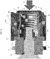
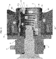
- Figure 8 is a cross-sectional view that illustrates a further assembly step of the wheel assembly including the anti-loosening device 1, to be implemented following the fastening of the single-nut unit 2 on the hub H.
- the anti-loosening device 1 By applying pressure on the outer surface of the gear 3, as indicated by the arrow F1 illustrated in Figure 8 , the anti-loosening device 1 is configured to position itself in a compressed configuration. In this configuration, the elastic element 5 is compressed, being configured to meet against an end portion of the wheel pin P. In the aforesaid compressed configuration, the gear 3 is in a decoupled position with respect to the inner teeth H3 of the wheel hub H. More specifically, the gear 3 is spaced within the wheel hub H in a more inner position with respect to the hub end H incorporating the inner teeth H3. As illustrated in Figure 8 , the gear 3 is arranged within a cavity portion 16 (also illustrated in Figures 2-4 and 6 ) obtained along the inner surface H2 of the wheel hub H.
- the cavity portion 16 is sized so as to define a space between the circumferential outer surface of the gear 3 having the outer teeth 4, and the inner surface of the aforesaid cavity portion 16. Thanks to this characteristic, by continuing to exert pressure on the gear 3, it is possible to rotate the anti-loosening device 1 around its main axis coinciding with the wheel-hub axis. As illustrated in the front view of Figure 9 , the rotation can be carried out in an anticlockwise direction (as indicated by the arrow F2) until reaching a position in which the coupling element 8 is radially aligned with respect to the aforesaid anti-rotation sector 9 of the single-nut unit 2. Of course, rotation of the anti-loosening device 1 can also be performed in a clockwise direction, to achieve the nut/anti-rotation sector 9 alignment.
- assembly of the wheel assembly proceeds by interrupting the pressure on the gear 3. Due to the interruption of the pressure exerted on the gear 3, the elastic element 5 is arranged to recall the gear 3, along the direction indicated by the arrow F3 in Figure 10 , into its engagement position with the inner teeth H3 of the wheel hub H, creating the assembled configuration of hub H, wheel W, device 1 and single-nut unit 2 shown in Figure 10 .
- This fastening member 10 comprises a head 17 arranged to cooperate with the aforesaid anti-rotation sector 9, in the condition coupled with the nut 8.
- the fastening member 10 can be made in the form of a threaded screw made of a particularly resistant material (e.g. titanium).
- the head 17 of the screw 10 cooperates with the aforesaid anti-rotation sector 9, so as to prevent mutual rotations between the single-nut unit 2 and the gear 3, by an angle greater than an angle defined by the size of the anti-rotation sector 9.
- this angle measures about 10°.
- the aforesaid angle, imposed by the main dimension of the anti-rotation sector 9, and which defines the maximum unloosening or over-screwing movement of the unit 2, is sized according to the number of teeth of the outer teeth 4, and the number of anti-rotation sectors 9 on the single-nut unit 2.
- the wheel assembly may have more than one anti-rotation sector 9 cooperating with a respective fastening member 10.
- the anti-loosening device 1 according to the invention offers the following advantages:
- one or more embodiments may concern a motor-vehicle wheel assembly comprising:
Abstract
Description
- The present invention relates to an anti-loosening device for a fastening unit of a motor-vehicle wheel, wherein the motor-vehicle wheel is configured to be coupled to a wheel hub by means of said fastening unit.
- In the field of high-performance cars, the use of single-nut fastening systems to fasten the wheels to the respective wheel hubs is widespread, as these systems allow significant reduction of the time required to change one or more wheels, compared to traditional fastening systems.
- The present invention starts from the desire to provide an anti-loosening device for a motor-vehicle wheel assembly comprising a single-nut fastening unit, and a related assembly method of the wheel assembly, which is particularly effective in preventing loosening or over-tightening of the fastening unit during operation, caused, for example, by the effect of the driving torque and the braking torque.
- The object of the present invention is to provide an anti-loosening device for a fastening unit of a motor-vehicle wheel that meets the above requirements.
- Another object of the invention is to provide an anti-loosening device that lends itself to be easily implemented, in order to minimize the anomalies resulting from loosening or over-tightening the locking unit.
- An additional object of the invention is to provide a simple, low-cost device that is uniquely usable for wheels and hubs arranged on both sides of a motor-vehicle.
- Another object of the invention is to propose an assembly method for assembling a motor-vehicle wheel assembly including a device of the type indicated above, which is particularly simple.
- In view of achieving these objects, the invention relates to an anti-loosening device for a fastening unit of a motor-vehicle wheel, wherein the motor-vehicle wheel is configured to be coupled with a wheel hub by means of said fastening unit, said anti-loosening device comprising:
- a gear having outer teeth arranged to cooperate with inner teeth of the wheel hub obtained at an end portion of the wheel hub along an inner surface thereof,
- an elastic element extending axially with respect to said gear, having a first end connected to the gear, and a second end configured to be engaged against at least one abutment and centering surface obtained inside the wheel hub,
- at least one coupling element obtained on a sector of said gear, arranged to receive a corresponding fastening member,
- said anti-loosening device being configured to be arranged within the wheel hub along an axial direction, so that a main axis of the anti-loosening device coincides with the wheel axis,
- said anti-loosening device being arranged to create a compressed configuration, wherein the gear is decoupled with respect to said inner teeth, and is arranged within a cavity portion obtained on the inner surface of the wheel hub, so as to allow rotation of the anti-loosening device around said main axis;
- wherein, following a rotation of said anti-loosening device, said coupling element is arranged to be radially aligned with respect to a respective anti-rotation sector obtained on said fastening unit, in such a way that said fastening member coupled to said coupling element cooperates with said anti-rotation sector, to avoid loosening of the locking unit.
- As specified in the attached claims, the present invention also relates to a motor-vehicle wheel assembly including the aforesaid device, and relative assembly method.
- Further characteristics and advantages of the invention will become apparent from the description that follows with reference to the attached drawings, provided purely by way of non-limiting example, wherein:
-
Figure 1 is an exploded perspective view illustrating a motor-vehicle wheel assembly including the device according to the present invention, -
Figures 2-4 are cross-sectional views that illustrate some preliminary steps of an assembly method for assembling the wheel assembly ofFigure 1 , -
Figure 5 is a front view of a partially assembled wheel assembly according to the criteria of the invention, -
Figures 6-11 are additional views that illustrate successive steps of the assembly method indicated above, and -
Figure 12 is a front view of the motor-vehicle wheel assembly including the anti-loosening device, in the final assembled condition. - In the following description various specific details are illustrated aimed at a thorough understanding of examples of one or more embodiments. The embodiments may be implemented without one or more of the specific details, or with other methods, components, materials, etc. In other cases, known structures, materials or operations are not shown or described in detail to avoid obscuring various aspects of the embodiments. The reference to "an embodiment" in the context of this description indicates that a particular configuration, structure or characteristic described in relation to the embodiment is included in at least one embodiment. Therefore, phrases such as "in an embodiment", possibly present in different places of this description do not necessarily refer to the same embodiment. Moreover, particular conformations, structures or characteristics can be combined in a suitable manner in one or more embodiments and/or associated with the embodiments in a different way from that illustrated here, for example, a characteristic here exemplified in relation to a figure may be applied to one or more embodiments exemplified in a different figure.
- The references illustrated here are only for convenience and do not therefore delimit the field of protection or the scope of the embodiments.
- It should be noted that the conformation of the components exemplified in the figures should not be considered in any way limiting, but representative of one of the multiple embodiments incorporating unique characteristics of the invention.
- In the attached drawings,
reference 1 generally indicates a preferred embodiment of an anti-loosening device for a fastening unit of a motor-vehicle wheel according to the present invention. -
Figure 1 is an exploded perspective view of a motor-vehicle wheel assembly including thedevice 1 according to the invention,Figure 1 - according to a technique known per se - shows a wheel hub structure U and a motor-vehicle wheel W arranged to be connected to the hub structure U. It is noted that the construction details relating to the tire of the wheel W are not presented here, since these details can be made in any known way, and also since elimination of these details from the drawings makes the latter more readily and easily understood. - The wheel hub structure U comprises:
- a wheel upright M provided with a plurality of attachment points A for connecting to one or more members of a motor-vehicle suspension (not shown in the drawings),
- a brake disc D arranged to cooperate with at least one braking member (for example, a brake caliper), and
- a wheel hub H projecting from the brake disc D in an axial direction.
- The reference D1 indicates a circumferential series of centering members, arranged protruding from the brake disc D along a direction parallel to the main axis of the hub H. As indicated in greater detail in the description that follows, these centering members D1 are designed to be selectively arranged within respective seats W1 obtained on the body of the wheel W, so as to achieve centering of the wheel W on the hub H. In the present description, the term "centering" means the correct angular positioning of the wheel W with respect to the hub H during assembly of the wheel W on the hub H, so as to transmit the driving torque and the braking torque. In alternative embodiments, the centering of the wheel W is carried out with the aid of a single centering member. Of course, the present invention is also applicable to the case in which these centering elements are not provided, since the transfer of the torque is carried out solely by means of the friction between the wheel and the hub without the use of driving devices.
- The wheel hub H comprises an end thread H1 arranged for reciprocal coupling with a single-
nut fastening unit 2 arranged to lock the wheel W on the hub H, once centering has occurred with respect to the latter. Greater details relative to thisfastening unit 2 are indicated below in the present description. -
Figure 2 illustrates an enlarged cross-sectional view of the wheel hub structure U shown in the previous figure. According to an architecture known per se, the unit U is configured to receive a wheel pin P therein. The wheel pin P can be connected in rotation with a respective axle shaft (not illustrated in the drawings) by means of an articulated homokinetic joint, so as to form a traction wheel assembly. The details relating to the connection of the axle shaft with the differential gear of the motor-vehicle, as well as those relating to the suspension of this wheel W are not illustrated here, as they can be made in any known way, and as these details taken alone, do not fall within the scope of the present invention. Of course, the invention can be applied to both drive wheels and non-drive wheels. - Returning to the exploded perspective view of the wheel assembly of
Figure 1 , theanti-loosening device 1 comprises agear 3 and anelastic element 5 extending axially with respect to thegear 3. Thegear 3 hasouter teeth 4 arranged to cooperate, in an assembled condition of the wheel assembly, with inner teeth H3 of the wheel hub H, obtained at an end portion H4 of the hub H, along an inner surface H2 thereof. More particularly, the inner teeth H3 are arranged on the end edge of the hub H. - The assembly steps for assembling the motor-vehicle wheel assembly illustrated in
Figure 1 , including theanti-loosening device 1, will now described in the description that follows. -
Figure 3 is a cross-sectional view that illustrates the wheel W centered on the wheel hub H. As indicated above, in this condition, the centering members D1 are arranged within respective seats W1 obtained on the body of the wheel W. - To easily center the wheel W with respect to the wheel hub H, a tool may be used (not illustrated in the drawings) incorporating the technical disclosures deriving from the patent application
EP 20165839.0 -
Figure 4 shows an enlarged cross-sectional view of the wheel W centered on the hub H, with theanti-loosening device 1 coupled to the wheel hub H. - Note how the
anti-loosening device 1 is configured to be inserted within the wheel hub H along an axial direction, so that the main axis of theanti-loosening device 1 coincides with the wheel-hub axis. Theouter teeth 4 of thegear 3 are configured to engage the inner teeth H3 of the wheel hub H. In the assembled condition illustrated inFigure 4 , theelastic element 5 is spaced along an axial direction with respect to thegear 3, in the direction of the wheel pin P protruding into the hub H from the side of the wheel upright M opposite the end of the hub H cooperating with thegear 3. - In one or more embodiments, as well as in that illustrated in the drawings, the
elastic element 5 is a conical helical spring with a progressively smaller diameter along a direction moving away from thegear 3. - The
elastic element 5 comprises afirst end 6 connected to thegear 3 and asecond end 7 configured to be engaged against at least one abutment and centering surface obtained inside the hub H. In one or more embodiments, as well as in the one illustrated in the drawings, this abutment and centering surface is defined by a wheel pin P extending within the hub H on the opposite side with respect to the inner teeth H3 (Figure 4 ). More specifically, thefirst end 6 can be integrated directly into the body of thegear 3, while thesecond end 7 can be fitted onto the end of the wheel pin P, so that saidsecond end 7 is supported by the wheel pin P, and is in abutment against an end portion of the wheel pin P. - In one or more embodiments, as well as in that illustrated in the drawings, the
gear 3 has an annular conformation in that it includes acentral hole 11 formed to allow drainage of water infiltrations possibly passing inside the assembled wheel assembly. Thecentral hole 11 is also designed to reduce the overall weight of thedevice 1, and to achieve the centering of a socket for screwing during assembly. - As illustrated in the attached drawings, the
anti-loosening device 1 further comprises acoupling element 8 obtained on a sector of thegear 3, along a direction substantially parallel to an axial direction of thegear 3. As will become clear from the following description, thecoupling element 8 is arranged to receive a corresponding fastening member 10 (illustrated inFigure 1 ). In one or more embodiments, as well as in that illustrated in the drawings, thecoupling element 8 is a threaded nut arranged to receive a corresponding threadedfastening screw 10. -
Figure 5 is a front perspective view of the components illustrated inFigure 4 , wherein the wheel W is centered on the hub H, with theanti-loosening device 1 coupled to the wheel hub H. In this condition, the wheel W is not yet locked onto the hub H, since thefastening unit 2 must still be applied onto the wheel-hub assembly. - In one or more embodiments, including that illustrated in the drawings, the wheel W has a series of recessed portions 12 (
Figure 1 ) arranged side by side on its inner circumferential wall. As illustrated in the assembled configuration ofFigure 5 , wherein the wheel is centered on the hub H and arranged against the brake disc D, some portions of the brake disc D remain visible from an observation direction corresponding to that illustrated inFigure 5 due to the aforesaid recessedportions 12. These recessedportions 12 are arranged to limit the contact between the wheel W and hub H during centering of the wheel, and to reduce the gluing effect by galvanic effect. In addition, the recessedportions 12 also allow reduction of the overall weight of the wheel assembly, and elimination of any humidity present inside. - Once the
anti-loosening device 1 is arranged within the hub H, with mutual engagement between theouter teeth 4 of thegear 3 and the inner teeth H3 of the hub H, in order to lock the wheel W onto the hub structure U, the single-nut fastening unit 2 is applied onto the wheel hub H. - Returning to
Figure 1 , thefastening unit 2 is defined by a single coupling nut having aninner thread 13 arranged to engage with the end thread H1 of the wheel hub H. The single-nut fastening unit 2 also comprises an outer portion withgrooves 14 so as to facilitate gripping of theunit 2. The single-nut unit 2 also has acentral hole 15, so that in the assembled condition of the wheel assembly, a part of the outer surface of thegear 3 is visible from the outside, despite the engagement of said single-nut fastening unit 2 on said wheel hub H. As will be evident from the following description, this characteristic is particularly relevant to allow an action on thedevice 1 despite the presence of the single-nut unit 2, as well as allowing the application of any friezes and/or marks. - As also indicated in the description that follows, the single-
nut unit 2 has at least one anti-rotation sector 9 (also illustrated inFigure 1 ), arranged at a portion of its inner circumferential wall defined by thecentral hole 15. In one or more embodiments, including those illustrated in the attached drawings, theanti-rotation sector 9 is defined by a cavity portion obtained along a sector of its inner circumferential wall. As indicated below, theanti-rotation sector 9 is configured to cooperate with thefastening member 10 engaged with thecoupling element 8 obtained on thegear 3. -
Figure 6 is a cross-sectional view that illustrates the wheel assembly including theanti-loosening device 1, with the single-nut fastening unit 2 tightened on the hub H. Note that the wheel W has a recess portion W2 arranged to receive the single-nut unit 2 screwed on the hub H. As indicated above, theinner thread 13 of theunit 2 is engaged with the thread H1 of the wheel hub H, in such a way that the wheel W is blocked on the hub H. -
Figure 7 is a front view of the wheel assembly with its components assembled in the configuration illustrated inFigure 6 . - As previously indicated, the single-
nut unit 2 has ananti-rotation sector 9 at a portion of its inner circumferential wall, defined by a cavity portion. In the light of the above, it will therefore be appreciated that, as illustrated inFigure 7 , following the screwing of the single-nut unit 2 onto the hub H, theanti-rotation sector 9 is found radially misaligned with respect to thecoupling element 8 of theanti-loosening device 1. -
Figure 8 is a cross-sectional view that illustrates a further assembly step of the wheel assembly including theanti-loosening device 1, to be implemented following the fastening of the single-nut unit 2 on the hub H. - By applying pressure on the outer surface of the
gear 3, as indicated by the arrow F1 illustrated inFigure 8 , theanti-loosening device 1 is configured to position itself in a compressed configuration. In this configuration, theelastic element 5 is compressed, being configured to meet against an end portion of the wheel pin P. In the aforesaid compressed configuration, thegear 3 is in a decoupled position with respect to the inner teeth H3 of the wheel hub H. More specifically, thegear 3 is spaced within the wheel hub H in a more inner position with respect to the hub end H incorporating the inner teeth H3. As illustrated inFigure 8 , thegear 3 is arranged within a cavity portion 16 (also illustrated inFigures 2-4 and 6 ) obtained along the inner surface H2 of the wheel hub H. Thecavity portion 16 is sized so as to define a space between the circumferential outer surface of thegear 3 having theouter teeth 4, and the inner surface of theaforesaid cavity portion 16. Thanks to this characteristic, by continuing to exert pressure on thegear 3, it is possible to rotate theanti-loosening device 1 around its main axis coinciding with the wheel-hub axis. As illustrated in the front view ofFigure 9 , the rotation can be carried out in an anticlockwise direction (as indicated by the arrow F2) until reaching a position in which thecoupling element 8 is radially aligned with respect to theaforesaid anti-rotation sector 9 of the single-nut unit 2. Of course, rotation of theanti-loosening device 1 can also be performed in a clockwise direction, to achieve the nut/anti-rotation sector 9 alignment. - Once the radial alignment between the
anti-rotation sector 9 of the single-nut unit 2 and thecoupling element 8 of theanti-loosening device 1 has been achieved, assembly of the wheel assembly proceeds by interrupting the pressure on thegear 3. Due to the interruption of the pressure exerted on thegear 3, theelastic element 5 is arranged to recall thegear 3, along the direction indicated by the arrow F3 inFigure 10 , into its engagement position with the inner teeth H3 of the wheel hub H, creating the assembled configuration of hub H, wheel W,device 1 and single-nut unit 2 shown inFigure 10 . - As illustrated in
Figures 11 and12 , once thecoupling element 8 and theanti-rotation sector 9 are radially aligned, it is possible to proceed by applying thefastening member 10 within the correspondingcoupling element 8. Thisfastening member 10 comprises ahead 17 arranged to cooperate with theaforesaid anti-rotation sector 9, in the condition coupled with thenut 8. Thefastening member 10 can be made in the form of a threaded screw made of a particularly resistant material (e.g. titanium). - Thanks to these characteristics, in the final assembled condition of the wheel assembly including the
anti-loosening device 1, thehead 17 of thescrew 10 cooperates with theaforesaid anti-rotation sector 9, so as to prevent mutual rotations between the single-nut unit 2 and thegear 3, by an angle greater than an angle defined by the size of theanti-rotation sector 9. Preferably, this angle measures about 10°. It will therefore be appreciated that, in the final assembled condition of the wheel assembly illustrated inFigure 12 , the interference between thescrew 10 and theanti-rotation sector 9, therefore, guarantees a block against unloosening or over-screwing of the single-nut unit 2, while the inner teeth of the wheel hub H and the outer teeth of thegear 3 ensure a stable coupling between the components. It should be noted that the aforesaid angle, imposed by the main dimension of theanti-rotation sector 9, and which defines the maximum unloosening or over-screwing movement of theunit 2, is sized according to the number of teeth of theouter teeth 4, and the number ofanti-rotation sectors 9 on the single-nut unit 2. In one or more alternative embodiments, the wheel assembly may have more than oneanti-rotation sector 9 cooperating with arespective fastening member 10. - Thanks to the above characteristics, the
anti-loosening device 1 according to the invention offers the following advantages: - the
anti-loosening device 1 lends itself to be easily implemented, in order to minimize the anomalies resulting from loosening or over-tightening the single-nut locking unit 2, and - the
anti-loosening device 1 is simple, low-cost and uniquely usable for wheels and hubs arranged on both sides of a motor-vehicle. - In light of the characteristics described above, one or more embodiments may concern a motor-vehicle wheel assembly comprising:
- a wheel hub H associated with a brake disc D,
- a motor-vehicle wheel W coupled to the wheel hub H so that the wheel axis coincides with the axis of the hub H,
- said motor-vehicle wheel W being locked on said wheel hub H by means of a
fastening unit 2 fixed on the wheel hub H, - said motor-vehicle wheel assembly further comprising an
anti-loosening device 1 coupled to said wheel hub H, comprising: - a
gear 3 inserted within said wheel hub H along an axial direction, havingouter teeth 4 cooperating with inner teeth H3 of the wheel hub H formed at an end portion H4 of the wheel hub H along an inner surface H2 thereof, - an
elastic element 5 extending axially with respect to saidgear 3 within said wheel hub H, wherein theelastic element 5 comprises afirst end 6 connected to thegear 3, and asecond end 7 engaged against at least one abutment and centering surface obtained inside the wheel hub H, - at least one
coupling element 8 obtained on a sector of saidgear 3 along a direction substantially parallel to an axial direction of thegear 3, wherein saidcoupling element 8 is arranged to receive acorresponding fastening member 10, - said
anti-loosening device 1 having a main axis coinciding with the axis of the wheel W and being arranged to create a compressed configuration, in which saidelastic element 5 is in a compressed position and thegear 3 is decoupled with respect to said inner teeth H3 of the wheel hub H, and is arranged within acavity portion 16 formed on the inner surface H2 of the wheel hub H, so as to allow rotation of theanti-loosening device 1 around said main axis; - wherein, following a rotation of said
anti-loosening device 1, saidcoupling element 8 is radially aligned with respect to arespective anti-rotation sector 9 obtained on saidfastening unit 2, - wherein, in the assembled condition of said wheel assembly, said
fastening member 10 coupled to saidcoupling element 8 cooperates with saidanti-rotation sector 9, to avoid loosening of thelocking unit 2. - One or more embodiments may relate to a method for assembling a motor-vehicle wheel assembly comprising the following steps:
- providing a support unit U to support a motor-vehicle wheel W, comprising a wheel hub H, a wheel upright M, a brake disc D and a series of centering members D1 protruding from the brake disc D,
- centering the wheel W on the wheel hub H, so that the axis of the wheel W coincides with the axis of the hub H.
- providing an
anti-loosening device 1 according to the characteristics indicated inclaim 1, - inserting said
anti-loosening device 1 inside said wheel hub H along an axial direction, in such a way that a main axis of theanti-loosening device 1 coincides with the wheel axis, saidouter teeth 4 cooperate with inner teeth H3 of the wheel hub H, saidelastic element 5 is spaced within said wheel hub H, and saidsecond end 7 of theelastic element 5 is engaged against at least one abutment and centering surface obtained inside the wheel hub H, - fixing a single-
nut fastening unit 2 on said wheel hub H to lock the wheel W onto the wheel hub H, said single-nut fastening unit 2 having acentral hole 15, so that in the assembled condition of the wheel assembly, a part of the outer surface of thegear 3 is visible from the outside despite the engagement of said single-nut fastening unit 2 on said wheel hub H, - applying pressure on said
gear 3 along an axial direction, so as to compress saidelastic element 5 and create a compressed configuration ofanti-loosening device 1, wherein thegear 3 is decoupled with respect to said inner teeth H3 of the wheel hub H, and is arranged within acavity portion 16 formed on the inner surface H2 of the wheel hub H, so as to allow rotation of theanti-loosening device 1 around said main axis, - rotating said
anti-loosening device 1 around said main axis to position thecoupling element 8 in a radially aligned position with respect to arespective anti-rotation sector 9 obtained on the single-nut fastening unit 2, - releasing said
gear 3 and allowing saidelastic element 5 to elastically recall thegear 3 into its position wherein saidouter teeth 4 cooperate with said inner teeth H3 of the wheel hub H, - tightening a
fastening member 10 inside saidcoupling element 8, in such a way that saidfastening member 10 coupled to saidcoupling element 8 obtained on thegear 3 cooperates with saidanti-rotation sector 9, to avoid loosening of thelocking unit 2. - Of course, without prejudice to the principle of the invention, the details of construction and the embodiments may vary widely with respect to those described and illustrated purely by way of example, without departing from the scope of the present invention.
Claims (15)
- An anti-loosening device (1) for a fastening unit (2) of a motor-vehicle wheel (W), wherein the motor-vehicle wheel (W) is configured to be coupled with a wheel hub (H) by means of said fastening unit (2), said anti-loosening device (1) comprising:- a gear (3) having outer teeth (4) arranged to cooperate with inner teeth (H3) of the wheel hub (H) obtained at an end portion (H4) of the wheel hub (H) along an inner surface (H3) thereof,- an elastic element (5) extending axially with respect to said gear (3), having a first end (6) connected to the gear (3), and a second end (7) configured to be engaged against at least one abutment and centering surface obtained inside the wheel hub (H),- at least one coupling element (8) obtained on a sector of said gear (3), arranged to receive a corresponding fastening member (10),- said anti-loosening device (1) being configured to be arranged within the wheel hub (H) along an axial direction, so that a main axis of the anti-loosening device (1) coincides with the wheel axis (W),- said anti-loosening device (1) being arranged to create a compressed configuration, wherein the gear (3) is decoupled with respect to said inner teeth (H3) and is arranged within a cavity portion (16) obtained on the inner surface (H2) of the wheel hub (H), so as to allow rotation of the anti-loosening device (1) around said main axis;- wherein, following a rotation of said anti-loosening device (1), said coupling element (8) is arranged to be radially aligned with respect to a respective anti-rotation sector (9) obtained on said fastening unit (2), in such a way that said fastening member (10) coupled to said coupling element (8) cooperates with said anti-rotation sector (9), to avoid loosening of the locking unit (2).
- An anti-loosening device (1) according to claim 1, wherein said elastic element (5) is a conical helical spring with a progressively smaller diameter along a direction moving away from said gear (3).
- An anti-loosening device (1) according to any one of the preceding claims, wherein said coupling element (8) is a threaded nut, arranged to receive a corresponding threaded screw.
- An anti-loosening device (1) according to any one of the preceding claims, wherein said gear (3) has a central hole (11) configured to allow drainage of water infiltrations possibly present in the wheel assembly including said device (1).
- A motor-vehicle wheel assembly comprising:- a wheel hub (H) associated with a brake disc (D),- a motor-vehicle wheel (W) coupled to the wheel hub (H) so that the wheel axis coincides with the axis of the hub (H),- said motor-vehicle wheel (W) being locked on said wheel hub (H) by means of a fastening unit 2 fixed on the wheel hub (H),- said motor-vehicle wheel assembly further comprising an anti-loosening device (1) coupled to said wheel hub (H), comprising:- a gear (3) inserted within said wheel hub (H) along an axial direction, having outer teeth (4) cooperating with inner teeth (H3) of the wheel hub (H) formed at an end portion (H4) of the wheel hub (H) along an inner surface (H2) thereof,- an elastic element (5) extending axially with respect to said gear (3) within said wheel hub (H), wherein the elastic element (5) comprises a first end (6) connected to the gear (3), and a second end (7) engaged against at least one abutment and centering surface obtained inside the wheel hub (H),- at least one coupling element (8) obtained on a sector of said gear (3) along a direction substantially parallel to an axial direction of the gear (3), wherein said coupling element (8) is arranged to receive a corresponding fastening member (10),- said anti-loosening device (1) having a main axis coinciding with the axis of the wheel W and being arranged to create a compressed configuration, wherein said elastic element (5) is in a compressed position, and the gear (3) is decoupled with respect to said inner teeth (H3) of the wheel hub (H), and is arranged within a cavity portion (16) formed on the inner surface (H2) of the wheel hub (H), so as to allow rotation of the anti-loosening device (1) around said main axis;- wherein, following a rotation of said anti-loosening device (1), said coupling element 8 is radially aligned with respect to a respective anti-rotation sector (9) obtained on said fastening unit (2),- wherein, in the assembled condition of said wheel assembly, said fastening member (10) coupled to said coupling element (8) cooperates with said anti-rotation sector (9), to avoid loosening of the locking unit (2).
- A motor-vehicle wheel assembly according to claim 5, wherein said fastening unit (2) is a single-nut fixing unit having an inner thread (13) arranged to cooperate with an end thread (H1) of the wheel hub (H).
- A motor-vehicle wheel assembly according to claim 6, wherein said single-nut fastening unit (2) comprises a central hole (15), so that in the assembled condition of the wheel assembly, a part of the outer surface of the gear (3) is visible from the outside despite the engagement of said single-nut fastening unit (2) on said wheel hub (H).
- A motor-vehicle wheel assembly according to claim 7, wherein said anti-rotation sector (9) is obtained at a sector of an inner circumferential wall of the single-nut fastening unit (2) defined by said central hole (15).
- A motor-vehicle wheel assembly according to claim 8, wherein said anti-rotation sector (9) is a cavity portion obtained at a sector of an inner circumferential wall of the single-nut fastening unit (2) defined by said central hole (15).
- A motor-vehicle wheel assembly according to claim 8, wherein said fastening member (10) is an anti-rotation screw having a head (17) arranged to be placed within a receptacle defined by said anti-rotation sector (9).
- A motor-vehicle wheel assembly according to claim 5, wherein said anti-rotation sector (9) has a main dimension which defines a maximum rotation angle of the fastening unit (2) with respect to the device (1), due to the interference between said fastening member (10) and said anti-rotation sector (9).
- A motor-vehicle wheel assembly according to claim 5, wherein said brake disc (D) is provided with at least one centering member (D1) protruding from the brake disc (D), said motor-vehicle wheel (W) having at least one seat (W1) selectively coupled with said at least one centering member (D1), so as to define the angular position of the wheel (W) on the wheel hub (H) during an assembly step.
- A motor-vehicle wheel assembly according to claim 5, wherein said second end (7) of the elastic element (5) is fitted on a wheel pin (P) protruding inside the hub (H) at a side opposite to said inner teeth (H3).
- A method for assembling a motor-vehicle wheel assembly comprising the following steps:- providing a support unit (U) to support a motor-vehicle wheel (W), comprising a wheel hub (H), a wheel upright (M), and a brake disc (D),- centering the wheel (W) on the wheel hub (H), so that the axis of the wheel (W) coincides with the axis of the hub (H).- providing an anti-loosening device (1) according to any one of claims 1-4,- inserting said anti-loosening device (1) inside said wheel hub (H) along an axial direction, in such a way that a main axis of the anti-loosening device (1) coincides with the wheel axis, said outer teeth (4) cooperate with inner teeth (H3) of the wheel hub (H), the elastic element (5) is spaced within said wheel hub (H), and said second end (7) of the elastic element (5) is engaged against at least one abutment and centering surface obtained inside the wheel hub (H),- fixing a single-nut fastening unit (2) on said wheel hub (H) to lock the wheel (W) onto the wheel hub (H), said single-nut fastening unit (2) having a central hole (15), so that in the assembled condition of the wheel assembly, a part of the outer surface of the gear (3) is visible from the outside despite the engagement of said single-nut fastening unit (2) on said wheel hub (H),- applying pressure on said gear (3) along an axial direction, so as to compress said elastic element (5) and create a compressed configuration of anti-loosening device (1), wherein the gear (3) is decoupled with respect to said inner teeth (H3) of the wheel hub (H) and is arranged within a cavity portion (16) formed on the inner surface (H2) of the wheel hub (H), so as to allow rotation of the anti-loosening device (1) around said main axis,- rotating said anti-loosening device (1) around said main axis to position the coupling element (8) in a radially aligned position with respect to a respective anti-rotation sector (9) obtained on the single-nut fastening unit (2),- releasing said gear (3), and allowing said elastic element (5) to elastically recall the gear (3) into its position wherein said outer teeth (4) cooperate with said inner teeth (H3) of the wheel hub (H),- tightening a fastening member (10) inside said coupling element (8), in such a way that said fastening member (10) coupled to said coupling element (8) obtained on the gear (3) cooperates with said anti-rotation sector (9), to avoid loosening of the locking unit (2).
- A method according to claim 14, wherein said step of centering the wheel (W) with respect to said centering members (D1), so as to define the angular position of the wheel (W) on the wheel hub (H), is carried out with the aid of a tool having a tubular body defining a coupling portion arranged for coupling to the wheel hub (H), and a carrier portion for supporting the motor-vehicle wheel (W) during a wheel centering step (W) on the hub (H).
Priority Applications (5)
| Application Number | Priority Date | Filing Date | Title |
|---|---|---|---|
| EP20174331.7A EP3909784B1 (en) | 2020-05-13 | 2020-05-13 | Motor-vehicle wheel assembly with an anti-loosening device |
| JP2020216759A JP7342333B2 (en) | 2020-05-13 | 2020-12-25 | Loosening prevention device for automobile wheel fasteners |
| BR102021000193-3A BR102021000193A2 (en) | 2020-05-13 | 2021-01-06 | ANTI-SOLUTURE DEVICE FOR A MOTOR VEHICLE WHEEL FIXING UNIT |
| US17/149,873 US11938754B2 (en) | 2020-05-13 | 2021-01-15 | Anti-loosening device for a fastening unit of a motor-vehicle wheel |
| CN202110271062.6A CN113665294B (en) | 2020-05-13 | 2021-03-12 | Anti-loosening device for a fastening unit for a motor vehicle wheel |
Applications Claiming Priority (1)
| Application Number | Priority Date | Filing Date | Title |
|---|---|---|---|
| EP20174331.7A EP3909784B1 (en) | 2020-05-13 | 2020-05-13 | Motor-vehicle wheel assembly with an anti-loosening device |
Publications (2)
| Publication Number | Publication Date |
|---|---|
| EP3909784A1 true EP3909784A1 (en) | 2021-11-17 |
| EP3909784B1 EP3909784B1 (en) | 2024-02-21 |
Family
ID=71266256
Family Applications (1)
| Application Number | Title | Priority Date | Filing Date |
|---|---|---|---|
| EP20174331.7A Active EP3909784B1 (en) | 2020-05-13 | 2020-05-13 | Motor-vehicle wheel assembly with an anti-loosening device |
Country Status (5)
| Country | Link |
|---|---|
| US (1) | US11938754B2 (en) |
| EP (1) | EP3909784B1 (en) |
| JP (1) | JP7342333B2 (en) |
| CN (1) | CN113665294B (en) |
| BR (1) | BR102021000193A2 (en) |
Families Citing this family (1)
| Publication number | Priority date | Publication date | Assignee | Title |
|---|---|---|---|---|
| CN114347718A (en) * | 2021-12-13 | 2022-04-15 | 上汽大众汽车有限公司 | Variable radius wheel hub |
Citations (5)
| Publication number | Priority date | Publication date | Assignee | Title |
|---|---|---|---|---|
| US3581609A (en) * | 1968-12-12 | 1971-06-01 | Eugene C Greenwood | Lock nut assembly and bolt and wrench for use therewith |
| US4591211A (en) * | 1984-10-12 | 1986-05-27 | Mr. Gasket Company | Lockable central nut for vehicle wheel mounting |
| US5846042A (en) * | 1997-06-24 | 1998-12-08 | Sony Corporation | Fastener/shaft locking and adjustment apparatus |
| DE102011011005A1 (en) * | 2011-02-11 | 2011-09-01 | Daimler Ag | Wheel securing system for motor vehicle, for fixing wheel rim on wheel hub by central wheel nut, has securing cap covering wheel nut and wheel hub, which on one side positively engages with wheel nut |
| DE102017124318A1 (en) * | 2017-10-18 | 2019-04-18 | Dr. Ing. H.C. F. Porsche Aktiengesellschaft | Mounting arrangement for a rim of a wheel |
Family Cites Families (6)
| Publication number | Priority date | Publication date | Assignee | Title |
|---|---|---|---|---|
| GB2394263B (en) * | 2002-10-15 | 2005-08-24 | Charles Robert Massie | Wheel nut locking assembly |
| DE102007061258B4 (en) * | 2007-12-19 | 2023-08-10 | Dr. Ing. H.C. F. Porsche Aktiengesellschaft | System for attaching a wheel to a motor vehicle |
| CA2671249A1 (en) * | 2008-07-08 | 2010-01-08 | Gregory James Bawden | Device for inhibiting unfastening rotation of rotary fasteners, particularly for vehicle wheels |
| CN107002739A (en) * | 2014-11-27 | 2017-08-01 | M·费尔曼 | Wheel keeps system |
| US20170166007A1 (en) * | 2015-12-10 | 2017-06-15 | Ford Global Technologies, Llc | Two-piece axle shaft |
| DE102018007928A1 (en) * | 2018-10-08 | 2019-03-28 | Daimler Ag | Central locking arrangement for a vehicle and vehicle |
-
2020
- 2020-05-13 EP EP20174331.7A patent/EP3909784B1/en active Active
- 2020-12-25 JP JP2020216759A patent/JP7342333B2/en active Active
-
2021
- 2021-01-06 BR BR102021000193-3A patent/BR102021000193A2/en unknown
- 2021-01-15 US US17/149,873 patent/US11938754B2/en active Active
- 2021-03-12 CN CN202110271062.6A patent/CN113665294B/en active Active
Patent Citations (5)
| Publication number | Priority date | Publication date | Assignee | Title |
|---|---|---|---|---|
| US3581609A (en) * | 1968-12-12 | 1971-06-01 | Eugene C Greenwood | Lock nut assembly and bolt and wrench for use therewith |
| US4591211A (en) * | 1984-10-12 | 1986-05-27 | Mr. Gasket Company | Lockable central nut for vehicle wheel mounting |
| US5846042A (en) * | 1997-06-24 | 1998-12-08 | Sony Corporation | Fastener/shaft locking and adjustment apparatus |
| DE102011011005A1 (en) * | 2011-02-11 | 2011-09-01 | Daimler Ag | Wheel securing system for motor vehicle, for fixing wheel rim on wheel hub by central wheel nut, has securing cap covering wheel nut and wheel hub, which on one side positively engages with wheel nut |
| DE102017124318A1 (en) * | 2017-10-18 | 2019-04-18 | Dr. Ing. H.C. F. Porsche Aktiengesellschaft | Mounting arrangement for a rim of a wheel |
Also Published As
| Publication number | Publication date |
|---|---|
| EP3909784B1 (en) | 2024-02-21 |
| CN113665294A (en) | 2021-11-19 |
| BR102021000193A2 (en) | 2021-11-23 |
| JP7342333B2 (en) | 2023-09-12 |
| US11938754B2 (en) | 2024-03-26 |
| JP2021178627A (en) | 2021-11-18 |
| CN113665294B (en) | 2024-03-08 |
| US20210354504A1 (en) | 2021-11-18 |
Similar Documents
| Publication | Publication Date | Title |
|---|---|---|
| CA2639265C (en) | Wheel hub | |
| JPS61115777A (en) | Steering knuckle-assembly | |
| US6371268B1 (en) | Retention mechanism for vehicle wheel assembly | |
| US11938754B2 (en) | Anti-loosening device for a fastening unit of a motor-vehicle wheel | |
| US6935005B2 (en) | Installation of, a hub/bearing assembly for an automotive vehicle | |
| AU759754B2 (en) | Wheel suspension, especially for nonpowered vehicle axles | |
| JPH09104204A (en) | Driving axle assembly | |
| US5927820A (en) | Hub-wheel assembly, in particular for a vehicle | |
| US6193320B1 (en) | Play-eliminating wheel fitting | |
| US6857835B2 (en) | Wheel end assembly with locking fastener | |
| EP1508710A1 (en) | A coupling device and a vehicle including such a device | |
| JP3706392B2 (en) | Single nut light alloy wheel equipment for automobiles | |
| US20040234185A1 (en) | Wheel bearing for a driven rigid axle | |
| US20060145531A1 (en) | Wheel fixing device particularly for go-karts or similar vehicles | |
| US5947613A (en) | Bearing and wheel hub retention system for wheel end assembly | |
| KR20110127952A (en) | Corner module for vehicle | |
| US11724540B2 (en) | Tool for mounting a motor-vehicle wheel on a wheel hub | |
| CN109416094B (en) | Axle end assembly including wheel brake and hub unit | |
| JP2001171306A (en) | Driving side wheel supporting device | |
| JP2914290B2 (en) | Car axle equipment | |
| JP2522905Y2 (en) | Hub mounting device | |
| JPS58126201A (en) | Assembled body of wheel with disk and central mounting section and brake rim | |
| JP2523394B2 (en) | Flexible joint for torque transmission with guide ring | |
| KR20210098800A (en) | Wheel bearing having improved wheel mounting structure | |
| JP2002337504A (en) | Method and tool for assembling bearing unit for driving wheel |
Legal Events
| Date | Code | Title | Description |
|---|---|---|---|
| PUAI | Public reference made under article 153(3) epc to a published international application that has entered the european phase |
Free format text: ORIGINAL CODE: 0009012 |
|
| STAA | Information on the status of an ep patent application or granted ep patent |
Free format text: STATUS: REQUEST FOR EXAMINATION WAS MADE |
|
| 17P | Request for examination filed |
Effective date: 20201124 |
|
| AK | Designated contracting states |
Kind code of ref document: A1 Designated state(s): AL AT BE BG CH CY CZ DE DK EE ES FI FR GB GR HR HU IE IS IT LI LT LU LV MC MK MT NL NO PL PT RO RS SE SI SK SM TR |
|
| B565 | Issuance of search results under rule 164(2) epc |
Effective date: 20201008 |
|
| STAA | Information on the status of an ep patent application or granted ep patent |
Free format text: STATUS: EXAMINATION IS IN PROGRESS |
|
| RIC1 | Information provided on ipc code assigned before grant |
Ipc: F16B 39/10 20060101ALI20220520BHEP Ipc: F16B 39/02 20060101ALI20220520BHEP Ipc: F16B 39/282 20060101ALI20220520BHEP Ipc: F16B 39/06 20060101ALI20220520BHEP Ipc: B60B 3/14 20060101AFI20220520BHEP |
|
| 17Q | First examination report despatched |
Effective date: 20220624 |
|
| GRAP | Despatch of communication of intention to grant a patent |
Free format text: ORIGINAL CODE: EPIDOSNIGR1 |
|
| STAA | Information on the status of an ep patent application or granted ep patent |
Free format text: STATUS: GRANT OF PATENT IS INTENDED |
|
| RAP3 | Party data changed (applicant data changed or rights of an application transferred) |
Owner name: STELLANTIS EUROPE S.P.A. |
|
| INTG | Intention to grant announced |
Effective date: 20231016 |
|
| GRAS | Grant fee paid |
Free format text: ORIGINAL CODE: EPIDOSNIGR3 |
|
| GRAA | (expected) grant |
Free format text: ORIGINAL CODE: 0009210 |
|
| STAA | Information on the status of an ep patent application or granted ep patent |
Free format text: STATUS: THE PATENT HAS BEEN GRANTED |
|
| AK | Designated contracting states |
Kind code of ref document: B1 Designated state(s): AL AT BE BG CH CY CZ DE DK EE ES FI FR GB GR HR HU IE IS IT LI LT LU LV MC MK MT NL NO PL PT RO RS SE SI SK SM TR |
|
| REG | Reference to a national code |
Ref country code: GB Ref legal event code: FG4D |
|
| REG | Reference to a national code |
Ref country code: CH Ref legal event code: EP |
|
| REG | Reference to a national code |
Ref country code: IE Ref legal event code: FG4D |
|
| REG | Reference to a national code |
Ref country code: DE Ref legal event code: R096 Ref document number: 602020025915 Country of ref document: DE |