EP3909664A1 - Aircraft air management systems for deactivating contaminants - Google Patents
Aircraft air management systems for deactivating contaminants Download PDFInfo
- Publication number
- EP3909664A1 EP3909664A1 EP21172789.6A EP21172789A EP3909664A1 EP 3909664 A1 EP3909664 A1 EP 3909664A1 EP 21172789 A EP21172789 A EP 21172789A EP 3909664 A1 EP3909664 A1 EP 3909664A1
- Authority
- EP
- European Patent Office
- Prior art keywords
- coating
- fibers
- management system
- air
- filter
- Prior art date
- Legal status (The legal status is an assumption and is not a legal conclusion. Google has not performed a legal analysis and makes no representation as to the accuracy of the status listed.)
- Pending
Links
- 239000000356 contaminant Substances 0.000 title 1
- 238000000576 coating method Methods 0.000 claims abstract description 64
- 239000011248 coating agent Substances 0.000 claims abstract description 61
- 239000000835 fiber Substances 0.000 claims abstract description 48
- 230000001143 conditioned effect Effects 0.000 claims abstract description 21
- 238000011144 upstream manufacturing Methods 0.000 claims abstract description 4
- 239000000463 material Substances 0.000 claims description 42
- 230000001699 photocatalysis Effects 0.000 claims description 25
- 238000000034 method Methods 0.000 claims description 16
- 230000001954 sterilising effect Effects 0.000 claims description 14
- 238000004659 sterilization and disinfection Methods 0.000 claims description 11
- 238000000231 atomic layer deposition Methods 0.000 claims description 10
- 229910052709 silver Inorganic materials 0.000 claims description 10
- 239000004332 silver Substances 0.000 claims description 10
- BQCADISMDOOEFD-UHFFFAOYSA-N Silver Chemical compound [Ag] BQCADISMDOOEFD-UHFFFAOYSA-N 0.000 claims description 8
- 230000002070 germicidal effect Effects 0.000 claims description 8
- 239000011148 porous material Substances 0.000 claims description 7
- 239000010949 copper Substances 0.000 claims description 5
- GUJOJGAPFQRJSV-UHFFFAOYSA-N dialuminum;dioxosilane;oxygen(2-);hydrate Chemical compound O.[O-2].[O-2].[O-2].[Al+3].[Al+3].O=[Si]=O.O=[Si]=O.O=[Si]=O.O=[Si]=O GUJOJGAPFQRJSV-UHFFFAOYSA-N 0.000 claims description 5
- 229910052901 montmorillonite Inorganic materials 0.000 claims description 5
- 239000010457 zeolite Substances 0.000 claims description 5
- RYGMFSIKBFXOCR-UHFFFAOYSA-N Copper Chemical compound [Cu] RYGMFSIKBFXOCR-UHFFFAOYSA-N 0.000 claims description 4
- 229910052802 copper Inorganic materials 0.000 claims description 4
- 230000003472 neutralizing effect Effects 0.000 claims description 4
- 150000003856 quaternary ammonium compounds Chemical class 0.000 claims description 3
- 239000010410 layer Substances 0.000 description 33
- GWEVSGVZZGPLCZ-UHFFFAOYSA-N Titan oxide Chemical compound O=[Ti]=O GWEVSGVZZGPLCZ-UHFFFAOYSA-N 0.000 description 11
- 238000002156 mixing Methods 0.000 description 11
- 238000004378 air conditioning Methods 0.000 description 7
- 241000894006 Bacteria Species 0.000 description 5
- 241000700605 Viruses Species 0.000 description 5
- XLOMVQKBTHCTTD-UHFFFAOYSA-N Zinc monoxide Chemical compound [Zn]=O XLOMVQKBTHCTTD-UHFFFAOYSA-N 0.000 description 5
- 230000007613 environmental effect Effects 0.000 description 5
- 239000004408 titanium dioxide Substances 0.000 description 5
- 238000007740 vapor deposition Methods 0.000 description 4
- 238000003618 dip coating Methods 0.000 description 3
- 239000012530 fluid Substances 0.000 description 3
- JKQOBWVOAYFWKG-UHFFFAOYSA-N molybdenum trioxide Chemical compound O=[Mo](=O)=O JKQOBWVOAYFWKG-UHFFFAOYSA-N 0.000 description 3
- 125000001453 quaternary ammonium group Chemical group 0.000 description 3
- 229910000077 silane Inorganic materials 0.000 description 3
- ZNOKGRXACCSDPY-UHFFFAOYSA-N tungsten trioxide Chemical compound O=[W](=O)=O ZNOKGRXACCSDPY-UHFFFAOYSA-N 0.000 description 3
- CSCPPACGZOOCGX-UHFFFAOYSA-N Acetone Chemical compound CC(C)=O CSCPPACGZOOCGX-UHFFFAOYSA-N 0.000 description 2
- 241000233866 Fungi Species 0.000 description 2
- PXHVJJICTQNCMI-UHFFFAOYSA-N Nickel Chemical compound [Ni] PXHVJJICTQNCMI-UHFFFAOYSA-N 0.000 description 2
- 239000005083 Zinc sulfide Substances 0.000 description 2
- MCMNRKCIXSYSNV-UHFFFAOYSA-N ZrO2 Inorganic materials O=[Zr]=O MCMNRKCIXSYSNV-UHFFFAOYSA-N 0.000 description 2
- 238000005229 chemical vapour deposition Methods 0.000 description 2
- 150000001875 compounds Chemical class 0.000 description 2
- 229920001577 copolymer Polymers 0.000 description 2
- PJXISJQVUVHSOJ-UHFFFAOYSA-N indium(iii) oxide Chemical compound [O-2].[O-2].[O-2].[In+3].[In+3] PJXISJQVUVHSOJ-UHFFFAOYSA-N 0.000 description 2
- 239000002052 molecular layer Substances 0.000 description 2
- 230000001590 oxidative effect Effects 0.000 description 2
- RVTZCBVAJQQJTK-UHFFFAOYSA-N oxygen(2-);zirconium(4+) Chemical compound [O-2].[O-2].[Zr+4] RVTZCBVAJQQJTK-UHFFFAOYSA-N 0.000 description 2
- 239000002245 particle Substances 0.000 description 2
- 238000005240 physical vapour deposition Methods 0.000 description 2
- 230000003134 recirculating effect Effects 0.000 description 2
- 238000004064 recycling Methods 0.000 description 2
- 238000005201 scrubbing Methods 0.000 description 2
- 238000005507 spraying Methods 0.000 description 2
- XOLBLPGZBRYERU-UHFFFAOYSA-N tin dioxide Chemical compound O=[Sn]=O XOLBLPGZBRYERU-UHFFFAOYSA-N 0.000 description 2
- 238000009423 ventilation Methods 0.000 description 2
- 239000011787 zinc oxide Substances 0.000 description 2
- 229910052984 zinc sulfide Inorganic materials 0.000 description 2
- 229920000049 Carbon (fiber) Polymers 0.000 description 1
- VYZAMTAEIAYCRO-UHFFFAOYSA-N Chromium Chemical compound [Cr] VYZAMTAEIAYCRO-UHFFFAOYSA-N 0.000 description 1
- QPLDLSVMHZLSFG-UHFFFAOYSA-N Copper oxide Chemical compound [Cu]=O QPLDLSVMHZLSFG-UHFFFAOYSA-N 0.000 description 1
- 239000005751 Copper oxide Substances 0.000 description 1
- BPQQTUXANYXVAA-UHFFFAOYSA-N Orthosilicate Chemical compound [O-][Si]([O-])([O-])[O-] BPQQTUXANYXVAA-UHFFFAOYSA-N 0.000 description 1
- RTAQQCXQSZGOHL-UHFFFAOYSA-N Titanium Chemical compound [Ti] RTAQQCXQSZGOHL-UHFFFAOYSA-N 0.000 description 1
- XHCLAFWTIXFWPH-UHFFFAOYSA-N [O-2].[O-2].[O-2].[O-2].[O-2].[V+5].[V+5] Chemical compound [O-2].[O-2].[O-2].[O-2].[O-2].[V+5].[V+5] XHCLAFWTIXFWPH-UHFFFAOYSA-N 0.000 description 1
- 229910052782 aluminium Inorganic materials 0.000 description 1
- XAGFODPZIPBFFR-UHFFFAOYSA-N aluminium Chemical compound [Al] XAGFODPZIPBFFR-UHFFFAOYSA-N 0.000 description 1
- 238000013459 approach Methods 0.000 description 1
- 230000009286 beneficial effect Effects 0.000 description 1
- 230000015572 biosynthetic process Effects 0.000 description 1
- 230000000903 blocking effect Effects 0.000 description 1
- 239000004917 carbon fiber Substances 0.000 description 1
- 239000003054 catalyst Substances 0.000 description 1
- 229910000420 cerium oxide Inorganic materials 0.000 description 1
- 238000004140 cleaning Methods 0.000 description 1
- 230000003749 cleanliness Effects 0.000 description 1
- 229910000428 cobalt oxide Inorganic materials 0.000 description 1
- IVMYJDGYRUAWML-UHFFFAOYSA-N cobalt(ii) oxide Chemical compound [Co]=O IVMYJDGYRUAWML-UHFFFAOYSA-N 0.000 description 1
- 238000004891 communication Methods 0.000 description 1
- 230000003750 conditioning effect Effects 0.000 description 1
- 229910000431 copper oxide Inorganic materials 0.000 description 1
- QUQFTIVBFKLPCL-UHFFFAOYSA-L copper;2-amino-3-[(2-amino-2-carboxylatoethyl)disulfanyl]propanoate Chemical compound [Cu+2].[O-]C(=O)C(N)CSSCC(N)C([O-])=O QUQFTIVBFKLPCL-UHFFFAOYSA-L 0.000 description 1
- 238000010586 diagram Methods 0.000 description 1
- AJNVQOSZGJRYEI-UHFFFAOYSA-N digallium;oxygen(2-) Chemical compound [O-2].[O-2].[O-2].[Ga+3].[Ga+3] AJNVQOSZGJRYEI-UHFFFAOYSA-N 0.000 description 1
- 238000001035 drying Methods 0.000 description 1
- 239000000428 dust Substances 0.000 description 1
- 230000001747 exhibiting effect Effects 0.000 description 1
- 238000001914 filtration Methods 0.000 description 1
- 239000010419 fine particle Substances 0.000 description 1
- 229910001195 gallium oxide Inorganic materials 0.000 description 1
- 239000007789 gas Substances 0.000 description 1
- 239000003365 glass fiber Substances 0.000 description 1
- PCHJSUWPFVWCPO-UHFFFAOYSA-N gold Chemical compound [Au] PCHJSUWPFVWCPO-UHFFFAOYSA-N 0.000 description 1
- 229910052737 gold Inorganic materials 0.000 description 1
- 239000010931 gold Substances 0.000 description 1
- 238000010438 heat treatment Methods 0.000 description 1
- 229910003437 indium oxide Inorganic materials 0.000 description 1
- AMGQUBHHOARCQH-UHFFFAOYSA-N indium;oxotin Chemical compound [In].[Sn]=O AMGQUBHHOARCQH-UHFFFAOYSA-N 0.000 description 1
- 238000009434 installation Methods 0.000 description 1
- 238000005259 measurement Methods 0.000 description 1
- 229910052751 metal Inorganic materials 0.000 description 1
- 239000002184 metal Substances 0.000 description 1
- 238000012986 modification Methods 0.000 description 1
- 230000004048 modification Effects 0.000 description 1
- 239000000178 monomer Substances 0.000 description 1
- 229910052759 nickel Inorganic materials 0.000 description 1
- 235000019645 odor Nutrition 0.000 description 1
- BMMGVYCKOGBVEV-UHFFFAOYSA-N oxo(oxoceriooxy)cerium Chemical compound [Ce]=O.O=[Ce]=O BMMGVYCKOGBVEV-UHFFFAOYSA-N 0.000 description 1
- BPUBBGLMJRNUCC-UHFFFAOYSA-N oxygen(2-);tantalum(5+) Chemical compound [O-2].[O-2].[O-2].[O-2].[O-2].[Ta+5].[Ta+5] BPUBBGLMJRNUCC-UHFFFAOYSA-N 0.000 description 1
- 238000010422 painting Methods 0.000 description 1
- 239000013618 particulate matter Substances 0.000 description 1
- 230000000737 periodic effect Effects 0.000 description 1
- 238000007747 plating Methods 0.000 description 1
- 239000002356 single layer Substances 0.000 description 1
- 239000007921 spray Substances 0.000 description 1
- 239000000126 substance Substances 0.000 description 1
- 229910001936 tantalum oxide Inorganic materials 0.000 description 1
- 239000010936 titanium Substances 0.000 description 1
- 229910052719 titanium Inorganic materials 0.000 description 1
- 238000012546 transfer Methods 0.000 description 1
- 229910001935 vanadium oxide Inorganic materials 0.000 description 1
- DRDVZXDWVBGGMH-UHFFFAOYSA-N zinc;sulfide Chemical compound [S-2].[Zn+2] DRDVZXDWVBGGMH-UHFFFAOYSA-N 0.000 description 1
Images


Classifications
-
- B—PERFORMING OPERATIONS; TRANSPORTING
- B01—PHYSICAL OR CHEMICAL PROCESSES OR APPARATUS IN GENERAL
- B01D—SEPARATION
- B01D53/00—Separation of gases or vapours; Recovering vapours of volatile solvents from gases; Chemical or biological purification of waste gases, e.g. engine exhaust gases, smoke, fumes, flue gases, aerosols
- B01D53/34—Chemical or biological purification of waste gases
- B01D53/74—General processes for purification of waste gases; Apparatus or devices specially adapted therefor
- B01D53/86—Catalytic processes
- B01D53/88—Handling or mounting catalysts
- B01D53/885—Devices in general for catalytic purification of waste gases
-
- A—HUMAN NECESSITIES
- A61—MEDICAL OR VETERINARY SCIENCE; HYGIENE
- A61L—METHODS OR APPARATUS FOR STERILISING MATERIALS OR OBJECTS IN GENERAL; DISINFECTION, STERILISATION OR DEODORISATION OF AIR; CHEMICAL ASPECTS OF BANDAGES, DRESSINGS, ABSORBENT PADS OR SURGICAL ARTICLES; MATERIALS FOR BANDAGES, DRESSINGS, ABSORBENT PADS OR SURGICAL ARTICLES
- A61L9/00—Disinfection, sterilisation or deodorisation of air
- A61L9/16—Disinfection, sterilisation or deodorisation of air using physical phenomena
- A61L9/18—Radiation
- A61L9/20—Ultraviolet radiation
-
- A—HUMAN NECESSITIES
- A61—MEDICAL OR VETERINARY SCIENCE; HYGIENE
- A61L—METHODS OR APPARATUS FOR STERILISING MATERIALS OR OBJECTS IN GENERAL; DISINFECTION, STERILISATION OR DEODORISATION OF AIR; CHEMICAL ASPECTS OF BANDAGES, DRESSINGS, ABSORBENT PADS OR SURGICAL ARTICLES; MATERIALS FOR BANDAGES, DRESSINGS, ABSORBENT PADS OR SURGICAL ARTICLES
- A61L9/00—Disinfection, sterilisation or deodorisation of air
- A61L9/16—Disinfection, sterilisation or deodorisation of air using physical phenomena
- A61L9/18—Radiation
- A61L9/20—Ultraviolet radiation
- A61L9/205—Ultraviolet radiation using a photocatalyst or photosensitiser
-
- B—PERFORMING OPERATIONS; TRANSPORTING
- B01—PHYSICAL OR CHEMICAL PROCESSES OR APPARATUS IN GENERAL
- B01D—SEPARATION
- B01D39/00—Filtering material for liquid or gaseous fluids
- B01D39/14—Other self-supporting filtering material ; Other filtering material
- B01D39/20—Other self-supporting filtering material ; Other filtering material of inorganic material, e.g. asbestos paper, metallic filtering material of non-woven wires
- B01D39/2003—Glass or glassy material
- B01D39/2017—Glass or glassy material the material being filamentary or fibrous
-
- B—PERFORMING OPERATIONS; TRANSPORTING
- B01—PHYSICAL OR CHEMICAL PROCESSES OR APPARATUS IN GENERAL
- B01D—SEPARATION
- B01D46/00—Filters or filtering processes specially modified for separating dispersed particles from gases or vapours
- B01D46/0027—Filters or filtering processes specially modified for separating dispersed particles from gases or vapours with additional separating or treating functions
- B01D46/0028—Filters or filtering processes specially modified for separating dispersed particles from gases or vapours with additional separating or treating functions provided with antibacterial or antifungal means
-
- B—PERFORMING OPERATIONS; TRANSPORTING
- B01—PHYSICAL OR CHEMICAL PROCESSES OR APPARATUS IN GENERAL
- B01D—SEPARATION
- B01D53/00—Separation of gases or vapours; Recovering vapours of volatile solvents from gases; Chemical or biological purification of waste gases, e.g. engine exhaust gases, smoke, fumes, flue gases, aerosols
- B01D53/007—Separation of gases or vapours; Recovering vapours of volatile solvents from gases; Chemical or biological purification of waste gases, e.g. engine exhaust gases, smoke, fumes, flue gases, aerosols by irradiation
-
- B—PERFORMING OPERATIONS; TRANSPORTING
- B01—PHYSICAL OR CHEMICAL PROCESSES OR APPARATUS IN GENERAL
- B01D—SEPARATION
- B01D53/00—Separation of gases or vapours; Recovering vapours of volatile solvents from gases; Chemical or biological purification of waste gases, e.g. engine exhaust gases, smoke, fumes, flue gases, aerosols
- B01D53/34—Chemical or biological purification of waste gases
- B01D53/74—General processes for purification of waste gases; Apparatus or devices specially adapted therefor
- B01D53/81—Solid phase processes
- B01D53/82—Solid phase processes with stationary reactants
-
- B—PERFORMING OPERATIONS; TRANSPORTING
- B60—VEHICLES IN GENERAL
- B60H—ARRANGEMENTS OF HEATING, COOLING, VENTILATING OR OTHER AIR-TREATING DEVICES SPECIALLY ADAPTED FOR PASSENGER OR GOODS SPACES OF VEHICLES
- B60H3/00—Other air-treating devices
- B60H3/0071—Electrically conditioning the air, e.g. by ionizing
- B60H3/0078—Electrically conditioning the air, e.g. by ionizing comprising electric purifying means
-
- B—PERFORMING OPERATIONS; TRANSPORTING
- B64—AIRCRAFT; AVIATION; COSMONAUTICS
- B64D—EQUIPMENT FOR FITTING IN OR TO AIRCRAFT; FLIGHT SUITS; PARACHUTES; ARRANGEMENT OR MOUNTING OF POWER PLANTS OR PROPULSION TRANSMISSIONS IN AIRCRAFT
- B64D13/00—Arrangements or adaptations of air-treatment apparatus for aircraft crew or passengers, or freight space
- B64D13/06—Arrangements or adaptations of air-treatment apparatus for aircraft crew or passengers, or freight space the air being conditioned
-
- F—MECHANICAL ENGINEERING; LIGHTING; HEATING; WEAPONS; BLASTING
- F24—HEATING; RANGES; VENTILATING
- F24F—AIR-CONDITIONING; AIR-HUMIDIFICATION; VENTILATION; USE OF AIR CURRENTS FOR SCREENING
- F24F8/00—Treatment, e.g. purification, of air supplied to human living or working spaces otherwise than by heating, cooling, humidifying or drying
- F24F8/10—Treatment, e.g. purification, of air supplied to human living or working spaces otherwise than by heating, cooling, humidifying or drying by separation, e.g. by filtering
- F24F8/108—Treatment, e.g. purification, of air supplied to human living or working spaces otherwise than by heating, cooling, humidifying or drying by separation, e.g. by filtering using dry filter elements
-
- F—MECHANICAL ENGINEERING; LIGHTING; HEATING; WEAPONS; BLASTING
- F24—HEATING; RANGES; VENTILATING
- F24F—AIR-CONDITIONING; AIR-HUMIDIFICATION; VENTILATION; USE OF AIR CURRENTS FOR SCREENING
- F24F8/00—Treatment, e.g. purification, of air supplied to human living or working spaces otherwise than by heating, cooling, humidifying or drying
- F24F8/10—Treatment, e.g. purification, of air supplied to human living or working spaces otherwise than by heating, cooling, humidifying or drying by separation, e.g. by filtering
- F24F8/15—Treatment, e.g. purification, of air supplied to human living or working spaces otherwise than by heating, cooling, humidifying or drying by separation, e.g. by filtering by chemical means
- F24F8/167—Treatment, e.g. purification, of air supplied to human living or working spaces otherwise than by heating, cooling, humidifying or drying by separation, e.g. by filtering by chemical means using catalytic reactions
-
- A—HUMAN NECESSITIES
- A61—MEDICAL OR VETERINARY SCIENCE; HYGIENE
- A61L—METHODS OR APPARATUS FOR STERILISING MATERIALS OR OBJECTS IN GENERAL; DISINFECTION, STERILISATION OR DEODORISATION OF AIR; CHEMICAL ASPECTS OF BANDAGES, DRESSINGS, ABSORBENT PADS OR SURGICAL ARTICLES; MATERIALS FOR BANDAGES, DRESSINGS, ABSORBENT PADS OR SURGICAL ARTICLES
- A61L2209/00—Aspects relating to disinfection, sterilisation or deodorisation of air
- A61L2209/10—Apparatus features
- A61L2209/12—Lighting means
-
- A—HUMAN NECESSITIES
- A61—MEDICAL OR VETERINARY SCIENCE; HYGIENE
- A61L—METHODS OR APPARATUS FOR STERILISING MATERIALS OR OBJECTS IN GENERAL; DISINFECTION, STERILISATION OR DEODORISATION OF AIR; CHEMICAL ASPECTS OF BANDAGES, DRESSINGS, ABSORBENT PADS OR SURGICAL ARTICLES; MATERIALS FOR BANDAGES, DRESSINGS, ABSORBENT PADS OR SURGICAL ARTICLES
- A61L2209/00—Aspects relating to disinfection, sterilisation or deodorisation of air
- A61L2209/10—Apparatus features
- A61L2209/13—Dispensing or storing means for active compounds
- A61L2209/134—Distributing means, e.g. baffles, valves, manifolds, nozzles
-
- A—HUMAN NECESSITIES
- A61—MEDICAL OR VETERINARY SCIENCE; HYGIENE
- A61L—METHODS OR APPARATUS FOR STERILISING MATERIALS OR OBJECTS IN GENERAL; DISINFECTION, STERILISATION OR DEODORISATION OF AIR; CHEMICAL ASPECTS OF BANDAGES, DRESSINGS, ABSORBENT PADS OR SURGICAL ARTICLES; MATERIALS FOR BANDAGES, DRESSINGS, ABSORBENT PADS OR SURGICAL ARTICLES
- A61L2209/00—Aspects relating to disinfection, sterilisation or deodorisation of air
- A61L2209/10—Apparatus features
- A61L2209/14—Filtering means
-
- A—HUMAN NECESSITIES
- A61—MEDICAL OR VETERINARY SCIENCE; HYGIENE
- A61L—METHODS OR APPARATUS FOR STERILISING MATERIALS OR OBJECTS IN GENERAL; DISINFECTION, STERILISATION OR DEODORISATION OF AIR; CHEMICAL ASPECTS OF BANDAGES, DRESSINGS, ABSORBENT PADS OR SURGICAL ARTICLES; MATERIALS FOR BANDAGES, DRESSINGS, ABSORBENT PADS OR SURGICAL ARTICLES
- A61L2209/00—Aspects relating to disinfection, sterilisation or deodorisation of air
- A61L2209/10—Apparatus features
- A61L2209/16—Connections to a HVAC unit
-
- B—PERFORMING OPERATIONS; TRANSPORTING
- B01—PHYSICAL OR CHEMICAL PROCESSES OR APPARATUS IN GENERAL
- B01D—SEPARATION
- B01D2239/00—Aspects relating to filtering material for liquid or gaseous fluids
- B01D2239/04—Additives and treatments of the filtering material
- B01D2239/0442—Antimicrobial, antibacterial, antifungal additives
-
- B—PERFORMING OPERATIONS; TRANSPORTING
- B01—PHYSICAL OR CHEMICAL PROCESSES OR APPARATUS IN GENERAL
- B01D—SEPARATION
- B01D2239/00—Aspects relating to filtering material for liquid or gaseous fluids
- B01D2239/04—Additives and treatments of the filtering material
- B01D2239/0471—Surface coating material
- B01D2239/0492—Surface coating material on fibres
-
- B—PERFORMING OPERATIONS; TRANSPORTING
- B01—PHYSICAL OR CHEMICAL PROCESSES OR APPARATUS IN GENERAL
- B01D—SEPARATION
- B01D2239/00—Aspects relating to filtering material for liquid or gaseous fluids
- B01D2239/10—Filtering material manufacturing
-
- B—PERFORMING OPERATIONS; TRANSPORTING
- B01—PHYSICAL OR CHEMICAL PROCESSES OR APPARATUS IN GENERAL
- B01D—SEPARATION
- B01D2255/00—Catalysts
- B01D2255/10—Noble metals or compounds thereof
- B01D2255/104—Silver
-
- B—PERFORMING OPERATIONS; TRANSPORTING
- B01—PHYSICAL OR CHEMICAL PROCESSES OR APPARATUS IN GENERAL
- B01D—SEPARATION
- B01D2255/00—Catalysts
- B01D2255/20—Metals or compounds thereof
- B01D2255/207—Transition metals
- B01D2255/20707—Titanium
-
- B—PERFORMING OPERATIONS; TRANSPORTING
- B01—PHYSICAL OR CHEMICAL PROCESSES OR APPARATUS IN GENERAL
- B01D—SEPARATION
- B01D2255/00—Catalysts
- B01D2255/20—Metals or compounds thereof
- B01D2255/207—Transition metals
- B01D2255/20761—Copper
-
- B—PERFORMING OPERATIONS; TRANSPORTING
- B01—PHYSICAL OR CHEMICAL PROCESSES OR APPARATUS IN GENERAL
- B01D—SEPARATION
- B01D2255/00—Catalysts
- B01D2255/40—Mixed oxides
-
- B—PERFORMING OPERATIONS; TRANSPORTING
- B01—PHYSICAL OR CHEMICAL PROCESSES OR APPARATUS IN GENERAL
- B01D—SEPARATION
- B01D2255/00—Catalysts
- B01D2255/50—Zeolites
-
- B—PERFORMING OPERATIONS; TRANSPORTING
- B01—PHYSICAL OR CHEMICAL PROCESSES OR APPARATUS IN GENERAL
- B01D—SEPARATION
- B01D2255/00—Catalysts
- B01D2255/80—Type of catalytic reaction
- B01D2255/802—Photocatalytic
-
- B—PERFORMING OPERATIONS; TRANSPORTING
- B01—PHYSICAL OR CHEMICAL PROCESSES OR APPARATUS IN GENERAL
- B01D—SEPARATION
- B01D2255/00—Catalysts
- B01D2255/90—Physical characteristics of catalysts
- B01D2255/915—Catalyst supported on particulate filters
-
- B—PERFORMING OPERATIONS; TRANSPORTING
- B01—PHYSICAL OR CHEMICAL PROCESSES OR APPARATUS IN GENERAL
- B01D—SEPARATION
- B01D2257/00—Components to be removed
- B01D2257/91—Bacteria; Microorganisms
-
- B—PERFORMING OPERATIONS; TRANSPORTING
- B01—PHYSICAL OR CHEMICAL PROCESSES OR APPARATUS IN GENERAL
- B01D—SEPARATION
- B01D2259/00—Type of treatment
- B01D2259/45—Gas separation or purification devices adapted for specific applications
- B01D2259/4566—Gas separation or purification devices adapted for specific applications for use in transportation means
- B01D2259/4575—Gas separation or purification devices adapted for specific applications for use in transportation means in aeroplanes or space ships
-
- B—PERFORMING OPERATIONS; TRANSPORTING
- B01—PHYSICAL OR CHEMICAL PROCESSES OR APPARATUS IN GENERAL
- B01D—SEPARATION
- B01D2259/00—Type of treatment
- B01D2259/80—Employing electric, magnetic, electromagnetic or wave energy, or particle radiation
- B01D2259/804—UV light
-
- B—PERFORMING OPERATIONS; TRANSPORTING
- B01—PHYSICAL OR CHEMICAL PROCESSES OR APPARATUS IN GENERAL
- B01D—SEPARATION
- B01D2279/00—Filters adapted for separating dispersed particles from gases or vapours specially modified for specific uses
- B01D2279/50—Filters adapted for separating dispersed particles from gases or vapours specially modified for specific uses for air conditioning
-
- B—PERFORMING OPERATIONS; TRANSPORTING
- B01—PHYSICAL OR CHEMICAL PROCESSES OR APPARATUS IN GENERAL
- B01D—SEPARATION
- B01D2279/00—Filters adapted for separating dispersed particles from gases or vapours specially modified for specific uses
- B01D2279/65—Filters adapted for separating dispersed particles from gases or vapours specially modified for specific uses for the sterilisation of air
-
- B—PERFORMING OPERATIONS; TRANSPORTING
- B60—VEHICLES IN GENERAL
- B60H—ARRANGEMENTS OF HEATING, COOLING, VENTILATING OR OTHER AIR-TREATING DEVICES SPECIALLY ADAPTED FOR PASSENGER OR GOODS SPACES OF VEHICLES
- B60H3/00—Other air-treating devices
- B60H3/06—Filtering
- B60H2003/0675—Photocatalytic filters
-
- B—PERFORMING OPERATIONS; TRANSPORTING
- B64—AIRCRAFT; AVIATION; COSMONAUTICS
- B64D—EQUIPMENT FOR FITTING IN OR TO AIRCRAFT; FLIGHT SUITS; PARACHUTES; ARRANGEMENT OR MOUNTING OF POWER PLANTS OR PROPULSION TRANSMISSIONS IN AIRCRAFT
- B64D13/00—Arrangements or adaptations of air-treatment apparatus for aircraft crew or passengers, or freight space
- B64D13/06—Arrangements or adaptations of air-treatment apparatus for aircraft crew or passengers, or freight space the air being conditioned
- B64D2013/0603—Environmental Control Systems
- B64D2013/0651—Environmental Control Systems comprising filters, e.g. dust filters
-
- B—PERFORMING OPERATIONS; TRANSPORTING
- B64—AIRCRAFT; AVIATION; COSMONAUTICS
- B64D—EQUIPMENT FOR FITTING IN OR TO AIRCRAFT; FLIGHT SUITS; PARACHUTES; ARRANGEMENT OR MOUNTING OF POWER PLANTS OR PROPULSION TRANSMISSIONS IN AIRCRAFT
- B64D13/00—Arrangements or adaptations of air-treatment apparatus for aircraft crew or passengers, or freight space
- B64D13/06—Arrangements or adaptations of air-treatment apparatus for aircraft crew or passengers, or freight space the air being conditioned
- B64D2013/0603—Environmental Control Systems
- B64D2013/0688—Environmental Control Systems with means for recirculating cabin air
Definitions
- Embodiments of the disclosure relate to an air management system used to provide air to one or more compartments within a vehicle, and more specifically, to a system for sterilizing a portion of the air within the air management system.
- Pressurized aircraft have integrated air management systems to provide a pressurized environment, fresh air transfer, recycling, heating, and air conditioning to maintain a comfortable safe environment for occupants for extended periods.
- Air recycling and replacing stale air requires continuous scrubbing for cleanliness to minimize airborne dust, dirt, odors, fungi and harmful microbes including viruses, spores, and bacteria.
- This cleaning or scrubbing of the air is typically performed via physical, electrostatic or chemical filtration, and often involve the use of filters and filter media such as a HEPA filter.
- filters and filter media such as a HEPA filter.
- microbes and dirt can accumulate and remain on the filter causing blockage with captured materials which may include active microbes. This blockage requires filters to be cleaned and replaced at periodic intervals. There is also a risk of release of these microbes and potential exposure to harmful microbes when the filters are being cleaned and replaced.
- an air management system of a vehicle having a conditioned area includes at least one duct defining a flow path for delivering air to the conditioned area and a filter arranged within the at least one duct upstream from the conditioned area.
- the filter includes a filter media having at least one filter media layer including a plurality of fibers.
- a coating is applied to at least a portion of the plurality of fibers and the coating is operable to deactivate a microbe arranged in contact with the coating.
- the coating is applied via one of atomic layer deposition, chemical vapor deposition, physical vapor deposition, dip coating, and spraying.
- a material of the coating includes copper , silver, and quaternary ammonium compound.
- the coating is a photocatalytic coating.
- the photocatalytic coating includes at least one of titanium dioxide, or zinc oxide.
- the filter media further includes at least one of silver, zeolites or montmorillonite to enhance photocatalytic activity of the photocatalytic coating.
- a sterilization system including at least one light source, wherein a light emitted by the at least one light source contacts the plurality of fibers.
- the at least one light source emits a germicidal ultraviolet light.
- the at least one light source is integrated into the filter.
- the at least one light source is mounted remotely from the filter.
- the sterilization system is operational when the air is actively circulating through a portion of the air management system.
- a first portion of the plurality of fibers within the at least one filter media layer has a first coating material and a second portion of the plurality of fibers within the at least one filter media layer has a second coating material, distinct from the first coating material.
- the first coating material is a non-photocatalytic material and the second coating material is a photocatalytic material.
- first portion of the plurality of fibers and the second portion of the plurality of fibers are arranged within a single filter media layer of the at least one filter media layer.
- the at least one filter media layer includes a first filter media layer and a second filter media layer, and the first portion of the plurality of fibers is arranged within the first filter media layer and the second portion of the plurality of fibers is arranged within the second filter media layer.
- an air source in fluid communication with the air source, a cabin air recirculation sub-system fluidly connected to an outlet of the conditioned area, an air mixing unit connected to the environmental control system and to the cabin air recirculation sub-system, and an air distribution system extending from the air mixing unit to one or more vents associated with the conditioned area.
- the at least one duct is a portion of the cabin air recirculation sub-system.
- the conditioned area is a cabin of an aircraft.
- the air is cabin recirculation air provided from an outlet of the conditioned area.
- a sterilization system including at least one light source operable to emit a light over the plurality of fibers, wherein the sterilization system is operational when the air is actively circulating through a portion of the air management system.
- a method of forming a filter capable of neutralizing microbes includes providing a filter media including a plurality of fibers and applying a coating to one or more fibers of the plurality of fibers via atomic layer deposition.
- the coating has a thickness less than an average pore size of the filter media and the coating is operable to deactivate a microbe arranged in contact with the coating.
- the coating is a photocatalytic material.
- the light is a germicidal ultraviolet light.
- the vehicle is an aircraft.
- installing the filter within an air management system of a vehicle further comprises installing the filter within a cabin air recirculation system of the air management system.
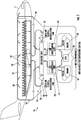
- FIG. 1 a schematic of an example of an air management system 10 to control the air of a vehicle, such as an aircraft 11 is illustrated.
- the aircraft 11 includes a conditioned area or cabin 12 that the air management system 10 controls.
- the cabin 12 may be configured to house people, cargo, and the like therein.
- the air management system 10 provides conditioned air to, and removes used or contaminated air from, the cabin 12.
- the air management system 10 includes an environmental control system 13 having at least one air conditioning unit or pack 14, and a cabin air recirculation sub-system 16. While the air management system 10 is illustrated and described herein with reference to an aircraft 11, it should be understood that the systems and techniques discussed herein may be used for a variety of air management systems 10.
- the cabin 12 may be replaced with any closed volume to be conditioned.
- systems described herein may be used with ship air management systems, such as submarines and cruise liners for example, personnel carrier air management systems, bus, trolley, train, or subway air management systems, or any other air management system that requires a continual supply of conditioned air.
- a medium such as air for example, is provided from one or more sources 18 to the air management system 10.
- suitable sources 18 include but are not limited to an engine of the aircraft 11 and an auxiliary power unit of the aircraft 11.
- the medium output from these sources 18 is provided to the one or more air conditioning units 14 of the environmental control system 13.
- the medium is conditioned. This conditioning includes altering one or more of a pressure, temperature, humidity, or flow rate of the medium based on an operating condition of the aircraft.
- the medium output or discharged from the one or more air conditioning units 14 of the environmental control system 13 may be used maintain a target range of pressures, temperatures, and/or humidity within the cabin 12.
- the medium discharged from the air conditioning units 14 is provided to an air mixing unit or mixing manifold 20 via one or more outlet ducts 22.
- at least one duct 24 of the cabin air recirculation sub-system 16 extends from the cabin 12 to the air mixing unit 20 to deliver air exhausted from the cabin 12 to the air mixing unit 20.
- the cabin recirculating air is mixed with the medium output from the one or more air conditioning units 14 to achieve a mixed medium having one or more desired parameters, such as temperature, pressure, and humidity for example.
- the mixed medium is delivered to the cabin 12 from the air mixing unit 20 via an air distribution system 26 including one or more conduits 28.
- the mixed medium may be delivered to the cabin 12 and cockpit via a ventilation system arranged near a ceiling of the cabin 12.
- the mixed medium typically circulates from the top of the cabin 12 toward the floor, and is distributed to a plurality of individual vents 30 of the ventilation system spaced laterally between the front and rear of the cabin 12.
- FIG. 2 an example of a portion of the cabin air recirculation sub-system within the air management system 10 is shown in more detail.
- a portion of the duct 24 of the cabin air recirculation sub-system 16 and fluidly connects one or more outlets 32 (see FIG. 1 ) of the cabin 12 to the air mixing unit 20.
- Mounted within the duct is a filter 40 configured to remove harmful microbes such as bacteria, viruses, spores, fungi and particulate matter from the cabin recirculation air provided from the outlets 32 in the cabin 12 as it flows through the filter 40.
- the filter 40 is shown as being arranged adjacent a downstream end of the duct, such as directly upstream from an interface between the duct and the air mixing unit, a filter arranged at any location within the duct is contemplated herein. Further, although the filter 40 is illustrated as having a circular configuration in FIG. 2 , and a rectangular configuration in FIG. 3 , it should be understood that a filter 40 having any configuration is within the scope of the disclosure. In an embodiment, the filter 40 comprises a HEPA-type filter. However, any suitable filter, or combination of multiple filters is within the scope of the disclosure.
- the duct 24 includes a recirculation fan 42 to establish an overpressure that is used to drive the flow of the recirculating cabin air through the filter 40 and to the air mixing unit 20.
- a recirculation fan 42 to establish an overpressure that is used to drive the flow of the recirculating cabin air through the filter 40 and to the air mixing unit 20.
- embodiments of a portion of a cabin air recirculation sub-system 16 that do not include a fan such that air flow through the duct 24 is driven by another source or by pressure for example, are also contemplated herein.
- the filter 40 typically includes a filter media 44 and a frame or other structure 46 for mounting the filter media 44 at a desired position within a duct, such as duct 24.
- the filter media 44 may include one or more layers.
- the filter media 44 includes at least a first layer 48a and a second layer 48b stacked in overlapping arrangement relative to a direction of fluid flow through the filter media 44.
- a filter media 44 having a single layer or alternatively, three, four, five, or more layers is also within the scope of the disclosure.
- the one or more layers 48 of filter media 44 typically consist of a plurality of fibers 50, such as glass fibers for example.
- fibers 50 such as glass fibers for example.
- any suitable type of fibers 50 including carbon fibers and metal fibers for example, are contemplated herein.
- the fibers 50 may be randomly oriented, or alternatively, may be unidirectionally oriented at any suitable angle within the layer. In embodiments including a plurality of layers, the orientation of the fibers 50 may vary between adjacent layers 48.
- the fibers 50 of the one or more layers of filter media 44 cooperate to form a tortuous fluid flow path that traps or adsorbs fine particles and microbes between adjacent fibers 50 or on the exposed surface of the fibers 50. In an existing filter, these particles, which include bacteria and viruses, typically remain trapped at the filter media 44 until the filter media 44 is cleaned and/or replaced.
- the fibers 50 integrated into the one or more layers of filter media 44 are coated with a material capable of deactivating or neutralizing any microbes, including bacteria and viruses, that contact the material.
- a material capable of deactivating or neutralizing any microbes, including bacteria and viruses that contact the material.
- examples of such materials include, but are not limited to copper (Cu), and silver (Ag).
- the coating material is a photocatalytic material, which as described herein is configured to deactivate or neutralize a microbe upon contact when the coating material is activated by a light having a specific wavelength. Any photocatalytic material exhibiting a suitable band gap which can be excited by incident light to create positive holes and electrons of sufficient energy to create oxidizing and reducing radicals may be suitable.
- photocatalytic materials include, but are not limited to, titanium dioxide (TiO2), doped titanium dioxide, zinc oxide (ZnO), stannic dioxide (Sn02), Cerium oxide (Ce02), tungsten trioxide (W03), cobalt oxide (Co304), indium oxide (In203), indium tin oxide (ITO), gallium oxide (Ga203), molybdenum trioxide (Mo03), zirconium dioxide (ZrO2), vanadium oxide (V205), tantalum oxide (Ta205), and zinc sulfide (ZnS) for example.
- the photocatalytic activity of the photocatalytic coating may be enhanced by combination with other materials.
- materials include but are not limited to, silver, zeolites and layered silicate materials such as montmorillonite.
- montomorlillonite may help to absorb light and enhance the effectiveness of titanium dioxide in creating oxidizing and reducing radicals that help to deactivate microbes.
- the fibers 50 within a layer of the filter media 44 may be coated with a single coating material, or alternatively, may be coated with a variety of coating materials including a combination of non-photocatalytic materials and photocatalytic materials.
- a first portion of the fibers 50 within a layer of the filter media 44 may be coated with copper or silver
- a second portion of the fibers 50 within the same layer of the filter media 44 may be coated with titanium dioxide.
- a third portion of the fibers 50 within the same layer of the filter media 44 may be coated with quaternary ammonium compound, such as quaternary ammonium silane monomers or copolymers for example.
- the total layered thickness of the coating applied to the fibers 50 may be less than the average pore size of the filter media 44.
- the average pore size as used herein refers to the effective size of the particles that the filter is able to capture.
- each layer of the coating material is a thin layer having a thickness less than the average pore size of the filter media 44. Accordingly, the one or more layers of coating material may each have a thickness less than or equal to 300 nm, 200 nm, or even 100 nm.
- vapor deposition such as atomic layer deposition for example, is used to form one or more of the layers of the coating applied to the fibers 50.
- Atomic layer deposition is a molecular layer-by-layer approach that results in a buildup where each layer has a thickness measured in angstroms (10 -10 ). Because the thickness of each layer that can be achieved via atomic layer deposition is so small, such a process may be particularly beneficial when forming a coating have a thickness less than a micron (10 -6 ).
- any suitable method for applying the coating material to the fibers 50 is contemplated herein. Examples of such methods include, but are not limited to chemical vapor deposition, and physical vapor deposition, dip coating, spraying or painting.
- the individual fibers 50 may be coated before or after being assembled to form the filter media 44 or cartridge, with the latter being more economical.
- application of a coating material via vapor deposition such as atomic layer deposition for example, permits non-line-of-sight coating because a molecular layer of the coating may be formed anywhere the vapor makes contact.
- the coating may be applied after both the formation and installation of the filter, since gases can penetrate the tiny pores of the fiber filter media.
- the fibers 50 may be coated by more than one method.
- a portion of the fibers 50 may be coated with photocatalytic material by atomic layer deposition, while a second portion of fibers 50 may be coated with quaternary ammonium silane compound by dip coating in a solution comprising acetone and a quaternary ammonium silane copolymer and drying in air.
- the coating materials being applied may be the same or different.
- the filter media 44 disclosed herein may be decontaminated or cleaned by emitting a light having a desired wavelength over the filter media 44.
- the light energizes the coating material or acts as a catalyst, causing the coating to neutralize or deactivate any microbes in contact therewith.
- This emission of light may be performed manually, or alternatively, may be performed automatically, such as by a sterilization system 52 integrated into the duct 24, adjacent the filter 40.
- the sterilization system 52 includes at least one light source 54 capable of emitting a light having a wavelength suitable to perform germicidal irradiation.
- the light source 54 is operable to emit a germicidal ultraviolet light, such as having a wavelength between about 200 and about 280 nanometers, also known as "UV-C.”
- a light having another wavelength, such as visible light for example is also within the scope of the disclosure.
- the light sources 54 of the sterilization system 52 may be operable intermittently, or in an embodiment, are operable whenever air is actively circulating through a portion of the air management system 10.
- one or more light sources 54 are mounted such that the light emitted therefrom projects over at least a portion, and in some embodiments, over the entire filter 40, and specifically, the filter media 44.
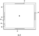
- the light sources 54 may be integrated into a portion of the filter 40 itself, such as the frame 46 for example, as shown in FIG. 5 .
- the one or more light sources 54 may be mounted remotely from the filter, such as within the duct 24 at a position adjacent the filter 40 or at a position axially offset from the filter 40.
- One or more interior surfaces 56 of the duct 24 or other surfaces within the region illuminated by the one or more light sources 54 may have a reflective or mirrored surface or coating to facilitate increased distribution of the germicidal light throughout the duct 24.
- a reflective or mirrored surface or coating as described herein may include, but is not limited to, one or more of aluminum, gold, chrome, nickel, titanium, copper, silver, copper oxide, titanium dioxide, zinc oxide, or another suitable shiny material or polished surface.
- such a coating may be applied via any suitable method, such as via a spray, dip, wipe, vapor deposition, plating, or other known method.
- the coating material is applied via vapor deposition, such as via atomic layer deposition for example. Application of a coating material via atomic layer deposition permits non-line-of-sight coating because a molecular layer of various germicidal chemical compounds may be formed anywhere the vapor makes contact.
- a filter media 44 having fibers 50 coated with a material capable of neutralizing microbes, such as a photocatalytic material for example, has an improved effectiveness in deactivating harmful microbes. As a result, the need to replace the filter cartridge may be reduced, and further, the potential exposure to harmful microbes during such replacement is reduced if not eliminated.
Landscapes
- Engineering & Computer Science (AREA)
- Chemical & Material Sciences (AREA)
- Health & Medical Sciences (AREA)
- Chemical Kinetics & Catalysis (AREA)
- Environmental & Geological Engineering (AREA)
- General Chemical & Material Sciences (AREA)
- General Health & Medical Sciences (AREA)
- Analytical Chemistry (AREA)
- Oil, Petroleum & Natural Gas (AREA)
- Life Sciences & Earth Sciences (AREA)
- Biomedical Technology (AREA)
- Mechanical Engineering (AREA)
- Veterinary Medicine (AREA)
- Animal Behavior & Ethology (AREA)
- Public Health (AREA)
- Epidemiology (AREA)
- Aviation & Aerospace Engineering (AREA)
- Pulmonology (AREA)
- Combustion & Propulsion (AREA)
- General Engineering & Computer Science (AREA)
- Toxicology (AREA)
- Geology (AREA)
- Disinfection, Sterilisation Or Deodorisation Of Air (AREA)
Abstract
Description
- Embodiments of the disclosure relate to an air management system used to provide air to one or more compartments within a vehicle, and more specifically, to a system for sterilizing a portion of the air within the air management system.
- Pressurized aircraft have integrated air management systems to provide a pressurized environment, fresh air transfer, recycling, heating, and air conditioning to maintain a comfortable safe environment for occupants for extended periods. Air recycling and replacing stale air requires continuous scrubbing for cleanliness to minimize airborne dust, dirt, odors, fungi and harmful microbes including viruses, spores, and bacteria. This cleaning or scrubbing of the air is typically performed via physical, electrostatic or chemical filtration, and often involve the use of filters and filter media such as a HEPA filter. However, microbes and dirt can accumulate and remain on the filter causing blockage with captured materials which may include active microbes. This blockage requires filters to be cleaned and replaced at periodic intervals. There is also a risk of release of these microbes and potential exposure to harmful microbes when the filters are being cleaned and replaced.
- According to an embodiment, an air management system of a vehicle having a conditioned area includes at least one duct defining a flow path for delivering air to the conditioned area and a filter arranged within the at least one duct upstream from the conditioned area. The filter includes a filter media having at least one filter media layer including a plurality of fibers. A coating is applied to at least a portion of the plurality of fibers and the coating is operable to deactivate a microbe arranged in contact with the coating.
- In addition to one or more of the features described above, or as an alternative, in further embodiments the coating is applied via one of atomic layer deposition, chemical vapor deposition, physical vapor deposition, dip coating, and spraying.
- In addition to one or more of the features described above, or as an alternative, in further embodiments a material of the coating includes copper , silver, and quaternary ammonium compound.
- In addition to one or more of the features described above, or as an alternative, in further embodiments the coating is a photocatalytic coating.
- In addition to one or more of the features described above, or as an alternative, in further embodiments the photocatalytic coating includes at least one of titanium dioxide, or zinc oxide.
- In addition to one or more of the features described above, or as an alternative, in further embodiments the filter media further includes at least one of silver, zeolites or montmorillonite to enhance photocatalytic activity of the photocatalytic coating.
- In addition to one or more of the features described above, or as an alternative, in further embodiments comprising a sterilization system including at least one light source, wherein a light emitted by the at least one light source contacts the plurality of fibers.
- In addition to one or more of the features described above, or as an alternative, in further embodiments the at least one light source emits a germicidal ultraviolet light.
- In addition to one or more of the features described above, or as an alternative, in further embodiments the at least one light source is integrated into the filter.
- In addition to one or more of the features described above, or as an alternative, in further embodiments the at least one light source is mounted remotely from the filter.
- In addition to one or more of the features described above, or as an alternative, in further embodiments the sterilization system is operational when the air is actively circulating through a portion of the air management system.
- In addition to one or more of the features described above, or as an alternative, in further embodiments a first portion of the plurality of fibers within the at least one filter media layer has a first coating material and a second portion of the plurality of fibers within the at least one filter media layer has a second coating material, distinct from the first coating material.
- In addition to one or more of the features described above, or as an alternative, in further embodiments the first coating material is a non-photocatalytic material and the second coating material is a photocatalytic material.
- In addition to one or more of the features described above, or as an alternative, in further embodiments the first portion of the plurality of fibers and the second portion of the plurality of fibers are arranged within a single filter media layer of the at least one filter media layer.
- In addition to one or more of the features described above, or as an alternative, in further embodiments the at least one filter media layer includes a first filter media layer and a second filter media layer, and the first portion of the plurality of fibers is arranged within the first filter media layer and the second portion of the plurality of fibers is arranged within the second filter media layer.
- In addition to one or more of the features described above, or as an alternative, in further embodiments comprising an air source, an environmental control system in fluid communication with the air source, a cabin air recirculation sub-system fluidly connected to an outlet of the conditioned area, an air mixing unit connected to the environmental control system and to the cabin air recirculation sub-system, and an air distribution system extending from the air mixing unit to one or more vents associated with the conditioned area.
- In addition to one or more of the features described above, or as an alternative, in further embodiments the at least one duct is a portion of the cabin air recirculation sub-system.
- In addition to one or more of the features described above, or as an alternative, in further embodiments the conditioned area is a cabin of an aircraft.
- In addition to one or more of the features described above, or as an alternative, in further embodiments the air is cabin recirculation air provided from an outlet of the conditioned area.
- In addition to one or more of the features described above, or as an alternative, in further embodiments comprising a sterilization system including at least one light source operable to emit a light over the plurality of fibers, wherein the sterilization system is operational when the air is actively circulating through a portion of the air management system.
- According to another embodiment, a method of forming a filter capable of neutralizing microbes includes providing a filter media including a plurality of fibers and applying a coating to one or more fibers of the plurality of fibers via atomic layer deposition. The coating has a thickness less than an average pore size of the filter media and the coating is operable to deactivate a microbe arranged in contact with the coating.
- In addition to one or more of the features described above, or as an alternative, in further embodiments the coating is a photocatalytic material.
- In addition to one or more of the features described above, or as an alternative, in further embodiments comprising applying at least one of silver, zeolites and montmorillonite to enhance photocatalytic activity of the photocatalytic material.
- In addition to one or more of the features described above, or as an alternative, in further embodiments comprising sterilizing the filter media by emitting a light that contacts the plurality of fibers.
- In addition to one or more of the features described above, or as an alternative, in further embodiments the light is a germicidal ultraviolet light.
- In addition to one or more of the features described above, or as an alternative, in further embodiments comprising installing the filter within an air management system of a vehicle having a conditioned area.
- In addition to one or more of the features described above, or as an alternative, in further embodiments the vehicle is an aircraft.
- In addition to one or more of the features described above, or as an alternative, in further embodiments installing the filter within an air management system of a vehicle further comprises installing the filter within a cabin air recirculation system of the air management system.
- The following descriptions should not be considered limiting in any way. With reference to the accompanying drawings, like elements are numbered alike:
-
FIG. 1 is a schematic diagram of an air management system of an aircraft; -
FIG. 2 is a perspective view of a portion of a duct of an air management system according to an embodiment; -
FIG. 3 is a cross-sectional view a filter according to an embodiment; -
FIG. 4 is a plan view of a layer of filter media of the filter ofFIG. 3 according to an embodiment; -
FIG. 5 is a front view of a filter mounted within a duct including a sterilization system according to an embodiment; and -
FIG. 6 is a cross-sectional view of a portion of a duct of an air management system including a sterilization system according to an embodiment. - A detailed description of one or more embodiments of the disclosed apparatus and method are presented herein by way of exemplification and not limitation with reference to the Figures.
- With reference now to
FIG. 1 , a schematic of an example of anair management system 10 to control the air of a vehicle, such as anaircraft 11 is illustrated. Theaircraft 11 includes a conditioned area orcabin 12 that theair management system 10 controls. Thecabin 12 may be configured to house people, cargo, and the like therein. Theair management system 10 provides conditioned air to, and removes used or contaminated air from, thecabin 12. Theair management system 10 includes anenvironmental control system 13 having at least one air conditioning unit orpack 14, and a cabinair recirculation sub-system 16. While theair management system 10 is illustrated and described herein with reference to anaircraft 11, it should be understood that the systems and techniques discussed herein may be used for a variety ofair management systems 10. For example, thecabin 12 may be replaced with any closed volume to be conditioned. As such, systems described herein may be used with ship air management systems, such as submarines and cruise liners for example, personnel carrier air management systems, bus, trolley, train, or subway air management systems, or any other air management system that requires a continual supply of conditioned air. - As shown in the
FIG. 1 , a medium, such as air for example, is provided from one ormore sources 18 to theair management system 10. Examples ofsuitable sources 18 include but are not limited to an engine of theaircraft 11 and an auxiliary power unit of theaircraft 11. The medium output from thesesources 18 is provided to the one or moreair conditioning units 14 of theenvironmental control system 13. Within theseair conditioning units 14, the medium is conditioned. This conditioning includes altering one or more of a pressure, temperature, humidity, or flow rate of the medium based on an operating condition of the aircraft. The medium output or discharged from the one or moreair conditioning units 14 of theenvironmental control system 13 may be used maintain a target range of pressures, temperatures, and/or humidity within thecabin 12. - The medium discharged from the
air conditioning units 14 is provided to an air mixing unit or mixingmanifold 20 via one ormore outlet ducts 22. Similarly, at least oneduct 24 of the cabinair recirculation sub-system 16 extends from thecabin 12 to theair mixing unit 20 to deliver air exhausted from thecabin 12 to theair mixing unit 20. Within theair mixing unit 20, the cabin recirculating air is mixed with the medium output from the one or moreair conditioning units 14 to achieve a mixed medium having one or more desired parameters, such as temperature, pressure, and humidity for example. - In an embodiment, the mixed medium is delivered to the
cabin 12 from theair mixing unit 20 via anair distribution system 26 including one ormore conduits 28. As shown, the mixed medium may be delivered to thecabin 12 and cockpit via a ventilation system arranged near a ceiling of thecabin 12. In some embodiments, the mixed medium typically circulates from the top of thecabin 12 toward the floor, and is distributed to a plurality ofindividual vents 30 of the ventilation system spaced laterally between the front and rear of thecabin 12. It should be understood that theair management system 10 illustrated and described herein is intended as an example only, and that any suitable air management system is within the scope of the disclosure. - With reference now to
FIG. 2 , an example of a portion of the cabin air recirculation sub-system within theair management system 10 is shown in more detail. In the illustrated, non-limiting embodiment, a portion of theduct 24 of the cabinair recirculation sub-system 16 and fluidly connects one or more outlets 32 (seeFIG. 1 ) of thecabin 12 to theair mixing unit 20. Mounted within the duct is afilter 40 configured to remove harmful microbes such as bacteria, viruses, spores, fungi and particulate matter from the cabin recirculation air provided from theoutlets 32 in thecabin 12 as it flows through thefilter 40. Although thefilter 40 is shown as being arranged adjacent a downstream end of the duct, such as directly upstream from an interface between the duct and the air mixing unit, a filter arranged at any location within the duct is contemplated herein. Further, although thefilter 40 is illustrated as having a circular configuration inFIG. 2 , and a rectangular configuration inFIG. 3 , it should be understood that afilter 40 having any configuration is within the scope of the disclosure. In an embodiment, thefilter 40 comprises a HEPA-type filter. However, any suitable filter, or combination of multiple filters is within the scope of the disclosure. Further, in an embodiment, theduct 24 includes arecirculation fan 42 to establish an overpressure that is used to drive the flow of the recirculating cabin air through thefilter 40 and to theair mixing unit 20. However, embodiments of a portion of a cabinair recirculation sub-system 16 that do not include a fan such that air flow through theduct 24 is driven by another source or by pressure for example, are also contemplated herein. - An example of a filter, such as the
HEPA filter 40 of the cabinair recirculation sub-system 16, is illustrated in more detail inFIGS. 3 and 4 . As shown, thefilter 40 typically includes afilter media 44 and a frame orother structure 46 for mounting thefilter media 44 at a desired position within a duct, such asduct 24. Thefilter media 44 may include one or more layers. For example, in the illustrated, non-limiting embodiment ofFIG. 3 , thefilter media 44 includes at least afirst layer 48a and asecond layer 48b stacked in overlapping arrangement relative to a direction of fluid flow through thefilter media 44. However, afilter media 44 having a single layer or alternatively, three, four, five, or more layers is also within the scope of the disclosure. - The one or more layers 48 of
filter media 44 typically consist of a plurality offibers 50, such as glass fibers for example. However, any suitable type offibers 50, including carbon fibers and metal fibers for example, are contemplated herein. Thefibers 50 may be randomly oriented, or alternatively, may be unidirectionally oriented at any suitable angle within the layer. In embodiments including a plurality of layers, the orientation of thefibers 50 may vary between adjacent layers 48. Thefibers 50 of the one or more layers offilter media 44 cooperate to form a tortuous fluid flow path that traps or adsorbs fine particles and microbes betweenadjacent fibers 50 or on the exposed surface of thefibers 50. In an existing filter, these particles, which include bacteria and viruses, typically remain trapped at thefilter media 44 until thefilter media 44 is cleaned and/or replaced. - In an embodiment, the
fibers 50 integrated into the one or more layers offilter media 44 are coated with a material capable of deactivating or neutralizing any microbes, including bacteria and viruses, that contact the material. Examples of such materials include, but are not limited to copper (Cu), and silver (Ag). Further, in an embodiment, the coating material is a photocatalytic material, which as described herein is configured to deactivate or neutralize a microbe upon contact when the coating material is activated by a light having a specific wavelength. Any photocatalytic material exhibiting a suitable band gap which can be excited by incident light to create positive holes and electrons of sufficient energy to create oxidizing and reducing radicals may be suitable. Examples of photocatalytic materials include, but are not limited to, titanium dioxide (TiO2), doped titanium dioxide, zinc oxide (ZnO), stannic dioxide (Sn02), Cerium oxide (Ce02), tungsten trioxide (W03), cobalt oxide (Co304), indium oxide (In203), indium tin oxide (ITO), gallium oxide (Ga203), molybdenum trioxide (Mo03), zirconium dioxide (ZrO2), vanadium oxide (V205), tantalum oxide (Ta205), and zinc sulfide (ZnS) for example. - In an embodiment, the photocatalytic activity of the photocatalytic coating may be enhanced by combination with other materials. Examples of such materials include but are not limited to, silver, zeolites and layered silicate materials such as montmorillonite. For example, montomorlillonite may help to absorb light and enhance the effectiveness of titanium dioxide in creating oxidizing and reducing radicals that help to deactivate microbes.
- The
fibers 50 within a layer of thefilter media 44 may be coated with a single coating material, or alternatively, may be coated with a variety of coating materials including a combination of non-photocatalytic materials and photocatalytic materials. For example, a first portion of thefibers 50 within a layer of thefilter media 44 may be coated with copper or silver, a second portion of thefibers 50 within the same layer of thefilter media 44 may be coated with titanium dioxide. Further, a third portion of thefibers 50 within the same layer of thefilter media 44 may be coated with quaternary ammonium compound, such as quaternary ammonium silane monomers or copolymers for example. - To avoid blocking or plugging of the pores of the
filter media 44, the total layered thickness of the coating applied to thefibers 50 may be less than the average pore size of thefilter media 44. The average pore size as used herein refers to the effective size of the particles that the filter is able to capture. Further, in an embodiment, each layer of the coating material is a thin layer having a thickness less than the average pore size of thefilter media 44. Accordingly, the one or more layers of coating material may each have a thickness less than or equal to 300 nm, 200 nm, or even 100 nm. - In an embodiment, vapor deposition, such as atomic layer deposition for example, is used to form one or more of the layers of the coating applied to the
fibers 50. Atomic layer deposition is a molecular layer-by-layer approach that results in a buildup where each layer has a thickness measured in angstroms (10-10). Because the thickness of each layer that can be achieved via atomic layer deposition is so small, such a process may be particularly beneficial when forming a coating have a thickness less than a micron (10-6). However, it should be understood that any suitable method for applying the coating material to thefibers 50 is contemplated herein. Examples of such methods include, but are not limited to chemical vapor deposition, and physical vapor deposition, dip coating, spraying or painting. With these various coating methods, theindividual fibers 50, or the fibers as woven to form a layer, may be coated before or after being assembled to form thefilter media 44 or cartridge, with the latter being more economical. Further, application of a coating material via vapor deposition, such as atomic layer deposition for example, permits non-line-of-sight coating because a molecular layer of the coating may be formed anywhere the vapor makes contact. By coating thefibers 50 using a non-line of sight coating method, the coating may be applied after both the formation and installation of the filter, since gases can penetrate the tiny pores of the fiber filter media. - In an embodiment, the
fibers 50 may be coated by more than one method. For example, a portion of thefibers 50 may be coated with photocatalytic material by atomic layer deposition, while a second portion offibers 50 may be coated with quaternary ammonium silane compound by dip coating in a solution comprising acetone and a quaternary ammonium silane copolymer and drying in air. In embodiments where different coating methods are used, the coating materials being applied may be the same or different. - In embodiments where the coating includes a photocatalytic coating, the
filter media 44 disclosed herein may be decontaminated or cleaned by emitting a light having a desired wavelength over thefilter media 44. The light energizes the coating material or acts as a catalyst, causing the coating to neutralize or deactivate any microbes in contact therewith. This emission of light may be performed manually, or alternatively, may be performed automatically, such as by asterilization system 52 integrated into theduct 24, adjacent thefilter 40. - With reference now to
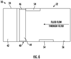
FIGS. 5 and6 , thesterilization system 52 includes at least onelight source 54 capable of emitting a light having a wavelength suitable to perform germicidal irradiation. In an embodiment, thelight source 54 is operable to emit a germicidal ultraviolet light, such as having a wavelength between about 200 and about 280 nanometers, also known as "UV-C." However, a light having another wavelength, such as visible light for example, is also within the scope of the disclosure. Additionally, alight source 54 having any configuration, such as an individual bulb, a light strip having a plurality of bulbs or light emitting diodes, or another type of emitter, is contemplated herein. Thelight sources 54 of thesterilization system 52 may be operable intermittently, or in an embodiment, are operable whenever air is actively circulating through a portion of theair management system 10. - In an embodiment, one or more
light sources 54 are mounted such that the light emitted therefrom projects over at least a portion, and in some embodiments, over theentire filter 40, and specifically, thefilter media 44. Thelight sources 54 may be integrated into a portion of thefilter 40 itself, such as theframe 46 for example, as shown inFIG. 5 . Alternatively, or in addition, the one or morelight sources 54 may be mounted remotely from the filter, such as within theduct 24 at a position adjacent thefilter 40 or at a position axially offset from thefilter 40. As a result of the light emitted by the one or morelight sources 54 over thefilter media 44, any viruses or bacteria present on thefilter 40, such as trapped by thefibers 50 in thefilter media 44 itself, are killed or neutralized. - One or more
interior surfaces 56 of theduct 24 or other surfaces within the region illuminated by the one or morelight sources 54 may have a reflective or mirrored surface or coating to facilitate increased distribution of the germicidal light throughout theduct 24. A reflective or mirrored surface or coating as described herein may include, but is not limited to, one or more of aluminum, gold, chrome, nickel, titanium, copper, silver, copper oxide, titanium dioxide, zinc oxide, or another suitable shiny material or polished surface. Further, such a coating may be applied via any suitable method, such as via a spray, dip, wipe, vapor deposition, plating, or other known method. In an embodiment, the coating material is applied via vapor deposition, such as via atomic layer deposition for example. Application of a coating material via atomic layer deposition permits non-line-of-sight coating because a molecular layer of various germicidal chemical compounds may be formed anywhere the vapor makes contact. - A
filter media 44 havingfibers 50 coated with a material capable of neutralizing microbes, such as a photocatalytic material for example, has an improved effectiveness in deactivating harmful microbes. As a result, the need to replace the filter cartridge may be reduced, and further, the potential exposure to harmful microbes during such replacement is reduced if not eliminated. - The term "about" is intended to include the degree of error associated with measurement of the particular quantity based upon the equipment available at the time of filing the application.
- The terminology used herein is for the purpose of describing particular embodiments only and is not intended to be limiting of the present disclosure. As used herein, the singular forms "a", "an" and "the" are intended to include the plural forms as well, unless the context clearly indicates otherwise. It will be further understood that the terms "comprises" and/or "comprising," when used in this specification, specify the presence of stated features, integers, steps, operations, elements, and/or components, but do not preclude the presence or addition of one or more other features, integers, steps, operations, element components, and/or groups thereof.
- While the present disclosure has been described with reference to an exemplary embodiment or embodiments, it will be understood by those skilled in the art that various changes may be made and equivalents may be substituted for elements thereof without departing from the scope of the present disclosure. In addition, many modifications may be made to adapt a particular situation or material to the teachings of the present disclosure without departing from the essential scope thereof. Therefore, it is intended that the present disclosure not be limited to the particular embodiment disclosed as the best mode contemplated for carrying out this present disclosure, but that the present disclosure will include all embodiments falling within the scope of the claims.
Claims (15)
- An air management system (10) of a vehicle having a conditioned area comprising:at least one duct (24) defining a flow path for delivering air to the conditioned area; anda filter (40) arranged within the at least one duct upstream from the conditioned area, the filter including a filter media having at least one filter media layer including a plurality of fibers, wherein a coating is applied to at least a portion of the plurality of fibers, the coating being operable to deactivate a microbe arranged in contact with the coating.
- The air management system of claim 1, wherein a material of the coating includes copper, silver, and quaternary ammonium compound.
- The air management system of claim 1 or 2, wherein the coating is a photocatalytic coating.
- The air management system of claim 3, wherein the filter media further includes at least one of silver, zeolites or montmorillonite to enhance photocatalytic activity of the photocatalytic coating is.
- The air management system of any preceding claim, further comprising a sterilization system including at least one light source, wherein a light emitted by the at least one light source contacts the plurality of fibers.
- The air management system of claim 5, wherein the at least one light source emits a germicidal ultraviolet light.
- The air management system of claim 5, wherein the sterilization system is operational when the air is actively circulating through a portion of the air management system.
- The air management system of any preceding claim, wherein the conditioned area is a cabin of an aircraft.
- A method of forming a filter capable of neutralizing microbes comprising:providing a filter media including a plurality of fibers; andapplying a coating to one or more fibers of the plurality of fibers via atomic layer deposition, wherein the coating has a thickness less than an average pore size of the filter media and the coating is operable to deactivate a microbe arranged in contact with the coating.
- The method of claim 9, wherein the coating is a photocatalytic material.
- The method of claim 10, further comprising applying at least one of silver, zeolites and montmorillonite to enhance photocatalytic activity of the photocatalytic material.
- The method of claim 9, further comprising sterilizing the filter media by emitting a light that contacts the plurality of fibers.
- The method of claim 12, wherein the light is a germicidal ultraviolet light.
- The method of claim 9, further comprising installing the filter within an air management system of a vehicle having a conditioned area.
- The method of claim 14, wherein the vehicle is an aircraft.
Applications Claiming Priority (2)
| Application Number | Priority Date | Filing Date | Title |
|---|---|---|---|
| US202063022950P | 2020-05-11 | 2020-05-11 | |
| US202063028193P | 2020-05-21 | 2020-05-21 |
Publications (1)
| Publication Number | Publication Date |
|---|---|
| EP3909664A1 true EP3909664A1 (en) | 2021-11-17 |
Family
ID=75870508
Family Applications (1)
| Application Number | Title | Priority Date | Filing Date |
|---|---|---|---|
| EP21172789.6A Pending EP3909664A1 (en) | 2020-05-11 | 2021-05-07 | Aircraft air management systems for deactivating contaminants |
Country Status (2)
| Country | Link |
|---|---|
| US (1) | US12042764B2 (en) |
| EP (1) | EP3909664A1 (en) |
Families Citing this family (3)
| Publication number | Priority date | Publication date | Assignee | Title |
|---|---|---|---|---|
| US20220032221A1 (en) * | 2020-07-31 | 2022-02-03 | Hamilton Sundstrand Corporation | Multifunctional composite microwave air purifier |
| US20230041184A1 (en) * | 2021-08-05 | 2023-02-09 | B/E Aerospace, Inc. | Multifunctional hydrophobic surface coatings for interior applications |
| US20240308669A1 (en) * | 2023-03-17 | 2024-09-19 | Hamilton Sundstrand Corporation | Energy recovery and thermal control utilizing heat pump |
Citations (7)
| Publication number | Priority date | Publication date | Assignee | Title |
|---|---|---|---|---|
| US5933702A (en) * | 1995-09-06 | 1999-08-03 | Universal Air Technology | Photocatalytic air disinfection |
| US20040251122A1 (en) * | 2003-06-16 | 2004-12-16 | University Of Florida | Photoelectrochemical air disinfection |
| US20080031783A1 (en) * | 2005-04-02 | 2008-02-07 | Briggs Daniel J | Photocatalytic fabric |
| WO2011037798A1 (en) * | 2009-09-22 | 2011-03-31 | 3M Innovative Properties Company | Method of applying atomic layer deposition coatings onto porous non-ceramic substrates |
| WO2015002324A1 (en) * | 2013-07-05 | 2015-01-08 | Nitto Denko Corporation | Filter element for decomposing contaminants, system for decomposing contaminants and method using the system |
| WO2015111770A1 (en) * | 2014-01-24 | 2015-07-30 | 주식회사 불스원신소재 | Method for manufacturing antibacterial filter using nonwoven fabric and activated carbon |
| KR102050278B1 (en) * | 2019-05-27 | 2019-12-02 | 동명대학교산학협력단 | air purifier with sterilization function |
Family Cites Families (10)
| Publication number | Priority date | Publication date | Assignee | Title |
|---|---|---|---|---|
| MX9302110A (en) | 1992-04-15 | 1994-05-31 | Schuller Int Inc | AIR FILTER AND METHOD TO REDUCE THE AMOUNT OF MICROORGANISMS IN CONTAMINATED AIR. |
| ITIS20050002A1 (en) | 2005-09-01 | 2007-03-02 | Jokero Inv Srl | Photocatalytic filters coated with suspensions of titanium dioxide and other compounds and methods for obtaining said filters. |
| WO2007033173A1 (en) | 2005-09-12 | 2007-03-22 | Argonide Corporation | Electrostatic air filter |
| GB0603138D0 (en) | 2006-02-16 | 2006-03-29 | Queen Mary & Westfield College | Virucidal materials |
| US8303693B2 (en) | 2007-04-26 | 2012-11-06 | The Hong Kong Polytechnic University | Nanofiber filter facemasks and cabin filters |
| FR2962348B1 (en) | 2010-07-12 | 2012-09-07 | Ind Du Ponant L | MICROBICIDAL FILTER AND FILTER CARTRIDGE INCORPORATING SUCH A FILTER |
| US9889939B2 (en) * | 2012-06-06 | 2018-02-13 | The Boeing Company | Environmental control system and methods of operating same |
| KR20140095875A (en) * | 2013-01-25 | 2014-08-04 | 서울바이오시스 주식회사 | Air purifying apparatus using ultraviolet light emitting diode |
| JP6124962B2 (en) * | 2015-08-31 | 2017-05-10 | 株式会社トクヤマ | Air conditioning method for aircraft and air conditioning system used in the method |
| US10981102B2 (en) | 2018-10-17 | 2021-04-20 | The Boeing Company | Aircraft air purification and volatile organic compounds reduction unit |
-
2021
- 2021-05-06 US US17/313,634 patent/US12042764B2/en active Active
- 2021-05-07 EP EP21172789.6A patent/EP3909664A1/en active Pending
Patent Citations (7)
| Publication number | Priority date | Publication date | Assignee | Title |
|---|---|---|---|---|
| US5933702A (en) * | 1995-09-06 | 1999-08-03 | Universal Air Technology | Photocatalytic air disinfection |
| US20040251122A1 (en) * | 2003-06-16 | 2004-12-16 | University Of Florida | Photoelectrochemical air disinfection |
| US20080031783A1 (en) * | 2005-04-02 | 2008-02-07 | Briggs Daniel J | Photocatalytic fabric |
| WO2011037798A1 (en) * | 2009-09-22 | 2011-03-31 | 3M Innovative Properties Company | Method of applying atomic layer deposition coatings onto porous non-ceramic substrates |
| WO2015002324A1 (en) * | 2013-07-05 | 2015-01-08 | Nitto Denko Corporation | Filter element for decomposing contaminants, system for decomposing contaminants and method using the system |
| WO2015111770A1 (en) * | 2014-01-24 | 2015-07-30 | 주식회사 불스원신소재 | Method for manufacturing antibacterial filter using nonwoven fabric and activated carbon |
| KR102050278B1 (en) * | 2019-05-27 | 2019-12-02 | 동명대학교산학협력단 | air purifier with sterilization function |
Also Published As
| Publication number | Publication date |
|---|---|
| US20210346841A1 (en) | 2021-11-11 |
| US12042764B2 (en) | 2024-07-23 |
Similar Documents
| Publication | Publication Date | Title |
|---|---|---|
| US12042764B2 (en) | Aircraft air management systems for deactivating contaminants | |
| US7371351B2 (en) | Photoelectrochemical air disinfection | |
| US9974881B2 (en) | Air purifying apparatus using ultra violet light emitting diode | |
| US7473304B2 (en) | Air filtration device for closed environments | |
| DE102018006769A1 (en) | Arrangement for irradiating a surface | |
| CN115297901A (en) | Air purification and sterilization unit | |
| US11629872B2 (en) | Single pass kill air purifier system and process of operation | |
| US6048499A (en) | Antiseptic clean system | |
| US20230088479A1 (en) | Vehicle with modular air treatment unit | |
| EP3904211B1 (en) | Integration of uv light into aircraft air management systems | |
| US20090162251A1 (en) | Air sterilization device with low aerosol bounce | |
| JP3543593B2 (en) | Gas cleaning method and apparatus | |
| EP3944869B1 (en) | Duct assemblies for air management systems and methods of manufacture | |
| KR20180079766A (en) | Air cleaner | |
| EP3945022A1 (en) | Multifunctional composite microwave air purifier | |
| US20220088261A1 (en) | Sanitizing system for vehicle compartment | |
| KR20150014822A (en) | air purifying apparatus having UV-LED and filter | |
| US20220047763A1 (en) | Antimicrobial systems for personal spaces | |
| US20250083101A1 (en) | Air cleaning device and air cleaning method | |
| JP2001327836A (en) | Transport equipment | |
| GB2298149A (en) | Clean room with antiseptic wall panels and photocatalyst in air conditioning system | |
| TR2021016520A2 (en) | MODULAR AIR DISINFECTION SYSTEM WITH WHITE LIGHT | |
| TR202011322A2 (en) | ENHANCED SYSTEM FOR HEALTHY AIR BREATHING IN INDOOR ENVIRONMENTS | |
| JP2017077996A (en) | Air purification vehicle glass and air purification system including the same |
Legal Events
| Date | Code | Title | Description |
|---|---|---|---|
| PUAI | Public reference made under article 153(3) epc to a published international application that has entered the european phase |
Free format text: ORIGINAL CODE: 0009012 |
|
| STAA | Information on the status of an ep patent application or granted ep patent |
Free format text: STATUS: THE APPLICATION HAS BEEN PUBLISHED |
|
| AK | Designated contracting states |
Kind code of ref document: A1 Designated state(s): AL AT BE BG CH CY CZ DE DK EE ES FI FR GB GR HR HU IE IS IT LI LT LU LV MC MK MT NL NO PL PT RO RS SE SI SK SM TR |
|
| B565 | Issuance of search results under rule 164(2) epc |
Effective date: 20211004 |
|
| STAA | Information on the status of an ep patent application or granted ep patent |
Free format text: STATUS: REQUEST FOR EXAMINATION WAS MADE |
|
| 17P | Request for examination filed |
Effective date: 20220516 |
|
| RBV | Designated contracting states (corrected) |
Designated state(s): AL AT BE BG CH CY CZ DE DK EE ES FI FR GB GR HR HU IE IS IT LI LT LU LV MC MK MT NL NO PL PT RO RS SE SI SK SM TR |
|
| STAA | Information on the status of an ep patent application or granted ep patent |
Free format text: STATUS: EXAMINATION IS IN PROGRESS |
|
| 17Q | First examination report despatched |
Effective date: 20240918 |