EP3909622A1 - Passive restart y-site - Google Patents
Passive restart y-site Download PDFInfo
- Publication number
- EP3909622A1 EP3909622A1 EP21179921.8A EP21179921A EP3909622A1 EP 3909622 A1 EP3909622 A1 EP 3909622A1 EP 21179921 A EP21179921 A EP 21179921A EP 3909622 A1 EP3909622 A1 EP 3909622A1
- Authority
- EP
- European Patent Office
- Prior art keywords
- valve
- chamber
- fluid
- flow port
- port
- Prior art date
- Legal status (The legal status is an assumption and is not a legal conclusion. Google has not performed a legal analysis and makes no representation as to the accuracy of the status listed.)
- Pending
Links
Images

Classifications
-
- A—HUMAN NECESSITIES
- A61—MEDICAL OR VETERINARY SCIENCE; HYGIENE
- A61M—DEVICES FOR INTRODUCING MEDIA INTO, OR ONTO, THE BODY; DEVICES FOR TRANSDUCING BODY MEDIA OR FOR TAKING MEDIA FROM THE BODY; DEVICES FOR PRODUCING OR ENDING SLEEP OR STUPOR
- A61M5/00—Devices for bringing media into the body in a subcutaneous, intra-vascular or intramuscular way; Accessories therefor, e.g. filling or cleaning devices, arm-rests
- A61M5/14—Infusion devices, e.g. infusing by gravity; Blood infusion; Accessories therefor
- A61M5/168—Means for controlling media flow to the body or for metering media to the body, e.g. drip meters, counters ; Monitoring media flow to the body
- A61M5/16804—Flow controllers
- A61M5/16827—Flow controllers controlling delivery of multiple fluids, e.g. sequencing, mixing or via separate flow-paths
-
- A—HUMAN NECESSITIES
- A61—MEDICAL OR VETERINARY SCIENCE; HYGIENE
- A61M—DEVICES FOR INTRODUCING MEDIA INTO, OR ONTO, THE BODY; DEVICES FOR TRANSDUCING BODY MEDIA OR FOR TAKING MEDIA FROM THE BODY; DEVICES FOR PRODUCING OR ENDING SLEEP OR STUPOR
- A61M5/00—Devices for bringing media into the body in a subcutaneous, intra-vascular or intramuscular way; Accessories therefor, e.g. filling or cleaning devices, arm-rests
- A61M5/14—Infusion devices, e.g. infusing by gravity; Blood infusion; Accessories therefor
- A61M5/1407—Infusion of two or more substances
- A61M5/1408—Infusion of two or more substances in parallel, e.g. manifolds, sequencing valves
-
- A—HUMAN NECESSITIES
- A61—MEDICAL OR VETERINARY SCIENCE; HYGIENE
- A61M—DEVICES FOR INTRODUCING MEDIA INTO, OR ONTO, THE BODY; DEVICES FOR TRANSDUCING BODY MEDIA OR FOR TAKING MEDIA FROM THE BODY; DEVICES FOR PRODUCING OR ENDING SLEEP OR STUPOR
- A61M1/00—Suction or pumping devices for medical purposes; Devices for carrying-off, for treatment of, or for carrying-over, body-liquids; Drainage systems
- A61M1/71—Suction drainage systems
- A61M1/78—Means for preventing overflow or contamination of the pumping systems
- A61M1/782—Means for preventing overflow or contamination of the pumping systems using valves with freely moving parts, e.g. float valves
-
- A—HUMAN NECESSITIES
- A61—MEDICAL OR VETERINARY SCIENCE; HYGIENE
- A61M—DEVICES FOR INTRODUCING MEDIA INTO, OR ONTO, THE BODY; DEVICES FOR TRANSDUCING BODY MEDIA OR FOR TAKING MEDIA FROM THE BODY; DEVICES FOR PRODUCING OR ENDING SLEEP OR STUPOR
- A61M39/00—Tubes, tube connectors, tube couplings, valves, access sites or the like, specially adapted for medical use
- A61M39/22—Valves or arrangement of valves
- A61M39/24—Check- or non-return valves
-
- A—HUMAN NECESSITIES
- A61—MEDICAL OR VETERINARY SCIENCE; HYGIENE
- A61M—DEVICES FOR INTRODUCING MEDIA INTO, OR ONTO, THE BODY; DEVICES FOR TRANSDUCING BODY MEDIA OR FOR TAKING MEDIA FROM THE BODY; DEVICES FOR PRODUCING OR ENDING SLEEP OR STUPOR
- A61M5/00—Devices for bringing media into the body in a subcutaneous, intra-vascular or intramuscular way; Accessories therefor, e.g. filling or cleaning devices, arm-rests
- A61M5/14—Infusion devices, e.g. infusing by gravity; Blood infusion; Accessories therefor
- A61M5/1407—Infusion of two or more substances
- A61M5/1409—Infusion of two or more substances in series, e.g. first substance passing through container holding second substance, e.g. reconstitution systems
-
- A—HUMAN NECESSITIES
- A61—MEDICAL OR VETERINARY SCIENCE; HYGIENE
- A61M—DEVICES FOR INTRODUCING MEDIA INTO, OR ONTO, THE BODY; DEVICES FOR TRANSDUCING BODY MEDIA OR FOR TAKING MEDIA FROM THE BODY; DEVICES FOR PRODUCING OR ENDING SLEEP OR STUPOR
- A61M5/00—Devices for bringing media into the body in a subcutaneous, intra-vascular or intramuscular way; Accessories therefor, e.g. filling or cleaning devices, arm-rests
- A61M5/14—Infusion devices, e.g. infusing by gravity; Blood infusion; Accessories therefor
- A61M5/1413—Modular systems comprising interconnecting elements
-
- A—HUMAN NECESSITIES
- A61—MEDICAL OR VETERINARY SCIENCE; HYGIENE
- A61M—DEVICES FOR INTRODUCING MEDIA INTO, OR ONTO, THE BODY; DEVICES FOR TRANSDUCING BODY MEDIA OR FOR TAKING MEDIA FROM THE BODY; DEVICES FOR PRODUCING OR ENDING SLEEP OR STUPOR
- A61M5/00—Devices for bringing media into the body in a subcutaneous, intra-vascular or intramuscular way; Accessories therefor, e.g. filling or cleaning devices, arm-rests
- A61M5/14—Infusion devices, e.g. infusing by gravity; Blood infusion; Accessories therefor
- A61M5/168—Means for controlling media flow to the body or for metering media to the body, e.g. drip meters, counters ; Monitoring media flow to the body
- A61M5/16804—Flow controllers
-
- A—HUMAN NECESSITIES
- A61—MEDICAL OR VETERINARY SCIENCE; HYGIENE
- A61M—DEVICES FOR INTRODUCING MEDIA INTO, OR ONTO, THE BODY; DEVICES FOR TRANSDUCING BODY MEDIA OR FOR TAKING MEDIA FROM THE BODY; DEVICES FOR PRODUCING OR ENDING SLEEP OR STUPOR
- A61M5/00—Devices for bringing media into the body in a subcutaneous, intra-vascular or intramuscular way; Accessories therefor, e.g. filling or cleaning devices, arm-rests
- A61M5/36—Devices for bringing media into the body in a subcutaneous, intra-vascular or intramuscular way; Accessories therefor, e.g. filling or cleaning devices, arm-rests with means for eliminating or preventing injection or infusion of air into body
- A61M5/40—Devices for bringing media into the body in a subcutaneous, intra-vascular or intramuscular way; Accessories therefor, e.g. filling or cleaning devices, arm-rests with means for eliminating or preventing injection or infusion of air into body using low-level float-valve to cut off media flow from reservoir
-
- A—HUMAN NECESSITIES
- A61—MEDICAL OR VETERINARY SCIENCE; HYGIENE
- A61M—DEVICES FOR INTRODUCING MEDIA INTO, OR ONTO, THE BODY; DEVICES FOR TRANSDUCING BODY MEDIA OR FOR TAKING MEDIA FROM THE BODY; DEVICES FOR PRODUCING OR ENDING SLEEP OR STUPOR
- A61M39/00—Tubes, tube connectors, tube couplings, valves, access sites or the like, specially adapted for medical use
- A61M39/22—Valves or arrangement of valves
- A61M39/24—Check- or non-return valves
- A61M2039/2433—Valve comprising a resilient or deformable element, e.g. flap valve, deformable disc
Definitions
- This invention relates in general to the field of medical fluid connectors, and in particular to a Y-site connector for use in medical infusion therapy.
- Medical infusion therapy involves the administration of medication through a needle or catheter.
- the medication may be administered using intravenous, intramuscular, or epidural techniques.
- infusion therapy includes a fluid source coupled to a patient's intravenous needle or a catheter through tubing.
- the fluid source which may comprise medication, a diluent, or any other fluid, is usually dripped from the fluid source, through the tubing, and into the patient.
- a Y-site device or connector (“Y-site”) may be installed in the fluid pathway between a fluid source and the patient.
- the Y-site provides a port where a secondary fluid source may be coupled to the fluid pathway established between a primary fluid source and the patient.
- a secondary fluid source may be coupled to the fluid pathway established between a primary fluid source and the patient.
- each fluid source is suspended at a specific height.
- a secondary fluid source containing medication may be joined to the fluid pathway having a primary fluid source containing a diluent such that the medication is delivered to the patient during fluid flow from the primary fluid source to the patient.
- An aspect of the present disclosure provides a fluid delivery Y-site device comprising: a chamber fluidly coupled between a primary flow port and an exit flow port; one or more a secondary flow port fluidly coupled to the chamber, the secondary flow port configured to conduct fluid to the chamber; and a valve positioned adjacent the primary flow port, the valve configured to move between an occluding configuration and an open configuration, based on a level of fluid within the chamber, such that the valve controls fluid flow through the primary flow port and into the chamber.
- a method of controlling fluid through a Y-site device comprising: providing a chamber fluidly coupled between a primary flow port and an exit flow port; providing a secondary flow port fluidly coupled to the chamber, the secondary flow port configured to conduct fluid to the chamber; providing a valve positioned adjacent the primary flow port; and moving, based on a level of fluid within the chamber, the valve between an occluding configuration and an open configuration, such that the valve controls fluid flow through the primary flow port and into the chamber.
- a phrase such as "an aspect” does not imply that such aspect is essential to the subject technology or that such aspect applies to all configurations of the subject technology.
- a disclosure relating to an aspect may apply to all configurations, or one or more configurations.
- An aspect may provide one or more examples of the disclosure.
- a phrase such as “an aspect” may refer to one or more aspects and vice versa.
- a phrase such as “an embodiment” does not imply that such embodiment is essential to the subject technology or that such embodiment applies to all configurations of the subject technology.
- a disclosure relating to an embodiment may apply to all embodiments, or one or more embodiments.
- An embodiment may provide one or more examples of the disclosure.
- a phrase such as "an embodiment” may refer to one or more embodiments and vice versa.
- a phrase such as "a configuration” does not imply that such configuration is essential to the subject technology or that such configuration applies to all configurations of the subject technology.
- a disclosure relating to a configuration may apply to all configurations, or one or more configurations.
- a configuration may provide one or more examples of the disclosure.
- a phrase such as "a configuration” may refer to one or more configurations and vice versa.
- FIG. 1 illustrates a passive restart Y-site 100 fluidly coupled to a primary fluid source 402 and a secondary fluid source 404.
- the passive restart Y-site 100 is configured to receive and control delivery of the primary fluid 402 and the secondary fluid 404 to a patient (not shown).
- the fluid is directed through an infusion pump (also not shown) prior to being directed to the patient.
- the passive restart Y-site 100 comprises a body 102 forming a chamber 104, two or more flow ports where fluid may enter the chamber 104, and a port where fluid may exit the chamber 104.
- the body 102 comprises a port where a primary fluid 402 may enter the body 102, a port where a secondary fluid 404 may enter the body 102, and a port for either fluid to exit the body 102.
- the body 102 comprises a top port 108 and a bottom port 110 with the chamber 104 therebetween.
- a side port 106 is fluidly connected to the chamber 104 between the top port 108 and bottom port 110.
- a primary fluid 402 may enter the chamber 104 from the top port 108, while a secondary fluid 404 may enter the chamber 104 from the side port 106. Fluid that enters the chamber 104 from either port may exit the chamber from the bottom port 110.
- a fluid source may be coupled with the top port 108 or side port 106 using a fluid fitting such as a luer-type fitting.
- the side port 106 comprises a needleless access valve 116.
- Flow of two or more fluids to a patient is passively controlled within the body 102. More specifically, flow of a primary fluid 402 from the top port 108 into the chamber 104 is reduced or halted upon the fluid within the chamber 104 exceeding a filling threshold.
- the filling threshold may be exceeded as a result of a primary fluid 402 entering the chamber 104 from the top port 108 or a secondary fluid 404 entering the chamber 104 from the side port 106.
- the flow of the primary fluid 402 from the top port 108 into the chamber 104 is reduced or halted by movement of a valve 114 and float 112.
- the fluid level within the chamber 104 When the fluid level within the chamber 104 drains through the exit or bottom port 110, the fluid level within the chamber 104 will decrease. When the fluid level is below the filling threshold, for example, when the secondary fluid flow 404 from the side port 106 into the chamber 104 is reduced or ceases, the valve 114 and float 112 follow the fluid level and move to allow the primary fluid 402 to once again flow into the chamber 104.
- the Y-site operates to prioritize communication of the fluid to the patient.
- the Y-site is designed to communicate the second fluid through the chamber before communicating the entire reservoir of the first fluid. It prioritizes what is communicated through the chamber by halting flow of the primary fluid until the secondary fluid has been communicated through the chamber.
- halting flow of the primary fluid 402 upon introduction of the secondary fluid 404 complete delivery of the secondary fluid 404 to the patient may be assured before flow of the primary fluid 402 is resumed.
- combined secondary fluid 404 and primary fluid 402 may be delivered to the patient in a specific ratio.
- the body 102 may be any shape, including a cylinder or elongate having a cross-section that is a sphere, square, or rectangle. In a preferred embodiment, the body is cylindrically shaped.
- the body 102 may be composed of any rigid material such as a polycarbonate, acrylonitrile butadiene styrene (ABS), or polystyrene.
- ABS acrylonitrile butadiene styrene
- the body 102 and chamber 104 may be a size that achieves the desired flow rate and volume. For example, the chamber 104 volume may be selected to achieve a specific flow rate or to retain specific float 112 or valve 114 sizes.
- the body 102 may further comprise a bleed off valve or filter (not shown), such as a hydrophobic filter, to allow air to escape from within the chamber 104.
- the body 102 comprises a lens or other visual indicator (not shown) of flow movement or float position within the body 102.
- the body 102 has a top port 108, a bottom port 110 opposite the top port 108, and a side port 106 disposed between the top port 108 and bottom port 110.
- the ports may be oriented in any location on the body 102.
- the top port 108 and side port 106 may be disposed at the top of the body 102 with each port having a respective flow path through the body 102 and into the chamber 104.
- any of the ports may be formed as a cap 118 coupled to the body 102.
- the cap 118 is removably coupled to the body, thereby providing access to the chamber 104.
- the cap 118 is adjustable to reduce or enlarge the chamber 104 volume, alter fluid flow through the chamber 104, or vary the buoyancy of the float 112.
- a valve guide 122 may be disposed in the chamber 104 proximate the top port 108.
- the valve guide 122 comprises and upper portion 132 and a lower portion 134.
- the perimeter of the upper portion 132 comprises a plurality of fingers (e.g., 136a, 136b, 136c) that extend from the lower portion 134.
- Adjacent fingers for example 136a and 136b, have opposing edges 138a and 138b separated apart by a distance.
- a lower edge 140 is formed between the opposing edges 138a and 138b by a top edge of the lower portion 134.
- Opposing edges 138a and 138b, and lower edge 140 create a peripheral opening through the perimeter of the upper portion 132.
- the lower potion 134 comprises one or more longitudinally oriented apertures 142 disposed through the cross-section of the valve guide 122.
- the apertures 142 are offset from the central axis of the valve guide 122.
- a valve 114 may be disposed in the chamber 104 proximate the top port 108 such that the valve 114 is positioned between the fingers 136a, 136b, 136c of the upper portion 132.
- the valve 114 may be cylindrically shaped with a convex and concaved surface, and wherein a circumferential edge of the concaved surface is engaged or is configured to engage with a lower portion 134 of the valve guide 122.
- a fluid flow from the top port 108 may enter the chamber 104 from an aperture 144 through the cap 118. The fluid may then pass over the convex surface and around the circumferential edge of the valve 114.
- the peripheral openings through the perimeter of the upper portion 132 allows the fluid to flow beneath the concave surface of the valve 114 and through the apertures 142 of the lower portion 134.
- the valve 114 is configured to occlude the aperture 144 of the top port 108 upon fluid within the chamber 104 exceeding a filling threshold. In some embodiments, the valve 114 only partially occludes the top port 108 upon exceeding a filling threshold, allowing flow from both the top port 108 and side port 106 into the chamber 104.
- the shape of the valve 114 is a large disk having a broad surface, wherein the valve 114 is activated by fluid pressure from a secondary fluid 404 flow upon the broad surface.
- the valve 114 is shaped as a cone, sphere, or any other shape that may be activated by fluid to occlude the top port 108.
- the valve 114 is elastically deformed when activated by the presence of fluid pressure within the chamber 104.
- the valve 114 may be fabricated from a malleable rubber, silicone, plastic, or thermoplastic elastomer.
- the valve 114 dimensions may be selected to achieve activation or movement of the valve 114 upon a specific fluid pressure.
- a valve 114 thickness may be selected to partially or fully occlude the top port 108 in response to a specified fluid level or fluid pressure.
- the valve 114 partially occludes the top port 108 at a first fluid pressure, and then fully occludes the top port 108 at a second fluid pressure.
- a valve seat 120 configured to retain the valve 114, may be disposed in the body 102 proximate the top port 108.
- a first side of the valve seat 120 may be formed as a circumferential ridge in the chamber 104 while the second side may be formed by the top port 108. In some embodiments, the second side of the valve seat may be an arcuate surface.
- a valve guide 122 may also be disposed in the chamber 104 proximal to the top port 108. In some embodiments, the valve seat 102 is configured to retain the valve guide 122 and valve 114. The valve guide 122 may be shaped as a basket to retain and guide the valve 114 in the chamber 104. The valve guide 122 may have one or more aperture through its cross-section to allow fluid flow through the valve guide 122. Preferably, the valve guide 122 is composed of a rigid material to protect against unintentional deformation of the valve 114.
- the float 112 may be disposed in the chamber 104 between the valve 114 and bottom port 110.
- the float 112 comprises specific buoyancy and is configured to move within the chamber 104 between the top port 108 and bottom port 110 in response to fluid flow.
- the float 112 may include a protrusion 124 that extends partially toward the valve 114. When the float 112 rises, the protrusion 124 may engage the valve 114, assuring the valve 114 remains in the activated position.
- the protrusion 124 and valve 114 are coupled, whereby the protrusion 124 and valve 114 move in unison within the chamber 104.
- An aperture through the valve guide 122 allows the protrusion 124 to pass through the valve guide 122 unobstructed.
- the float 112 comprises radial protrusions or grooves on an outer surface to allow fluid flow past the float 112 when the float is in contact with a port. For example, fluid may continue to exit the chamber 104 when the float is in a lowered position that would otherwise occlude the bottom port 110.
- the float 112 or chamber 104 comprises an annular ring 126 or seat such that the bottom port 110 becomes occluded when the float 112 is in a lowermost position, thereby preventing air from passing through the chamber 104 to the patient.
- the float 112 may comprise specific buoyancy such that a specific fluid level within the chamber causes the float 112 to rise or lower in the chamber.
- the float may be solid or hollow, and may comprise air or foam.
- the material used to fabricate the float 112 will not degrade in the particular environment.
- all or a portion of the float 112 is coated with a non-degrading material.
- the buoyancy characteristics of the float 112 may be varied by rotation of a dial or selector.
- the float 112 may be configured as two portions coupled together. The two portions of the float 112 may be rotated to increase or decrease the volume within the float 112.
- the buoyancy of the float 112 is varied by altering the interior volume of the float 112.
- the float 112 may be configured with an inner bladder fillable through a valve in a surface of the float 112.
- valve 114 During fluid flow from the top port 108 the valve 114 would remain in an open or deactivated position, and the float 112 would remain between the valve 114 and bottom port 110, thereby allowing fluid flow from the top port 108 to enter the chamber 104 and exit from the bottom port 110.
- a filling threshold such as by introduction of a fluid flow from the side port 106 or from the top port 108, the fluid would cause the valve 114 to be activated and occlude the top port 108.
- the float 112 may rise and engage the valve 114, assuring the valve 114 remains activated.
- the valve 114 and float 112 are configured to partially occlude the top port 108, allowing a combined fluid flow from the top port 108 and side port 106 to enter the chamber 104 and exit from the bottom port 110.
- an open position would be achieved.
- the float 112 would lower and the valve 114 would disengage or open, thereby allowing fluid flow from the top port 108 to enter the chamber 104 and exit from the bottom port 110.
- the float 112 comprises two or more protrusions 124 configured to engage a valve 114.
- the body 102 comprises two or more chambers 104 and floats 112, allowing for two or more primary fluids 402 or secondary fluids 404 to be coupled with the passive restart Y-site 100 as illustrated in FIG. 5 .
- a selector may be utilized to determine the sequence of primary or secondary flows into the chamber 104.
- the phrase "at least one of' preceding a series of items, with the term “and” or “or” to separate any of the items, modifies the list as a whole, rather than each member of the list (i.e., each item).
- phrases “at least one of A, B, and C” or “at least one of A, B, or C” each refer to only A, only B, or only C; any combination of A, B, and C; and/or at least one of each of A, B, and C.
Abstract
Description
- This invention relates in general to the field of medical fluid connectors, and in particular to a Y-site connector for use in medical infusion therapy.
- Medical infusion therapy involves the administration of medication through a needle or catheter. The medication may be administered using intravenous, intramuscular, or epidural techniques. Typically, infusion therapy includes a fluid source coupled to a patient's intravenous needle or a catheter through tubing. The fluid source, which may comprise medication, a diluent, or any other fluid, is usually dripped from the fluid source, through the tubing, and into the patient. To facilitate the introduction of an additional fluid into the patient, a Y-site device or connector ("Y-site") may be installed in the fluid pathway between a fluid source and the patient.
- The Y-site provides a port where a secondary fluid source may be coupled to the fluid pathway established between a primary fluid source and the patient. To control the flow of fluid from the primary and secondary fluid source, each fluid source is suspended at a specific height. For example, a secondary fluid source containing medication may be joined to the fluid pathway having a primary fluid source containing a diluent such that the medication is delivered to the patient during fluid flow from the primary fluid source to the patient.
- An aspect of the present disclosure provides a fluid delivery Y-site device comprising: a chamber fluidly coupled between a primary flow port and an exit flow port; one or more a secondary flow port fluidly coupled to the chamber, the secondary flow port configured to conduct fluid to the chamber; and a valve positioned adjacent the primary flow port, the valve configured to move between an occluding configuration and an open configuration, based on a level of fluid within the chamber, such that the valve controls fluid flow through the primary flow port and into the chamber.
- According to certain implementations of the present disclosure, a method of controlling fluid through a Y-site device, comprising: providing a chamber fluidly coupled between a primary flow port and an exit flow port; providing a secondary flow port fluidly coupled to the chamber, the secondary flow port configured to conduct fluid to the chamber; providing a valve positioned adjacent the primary flow port; and moving, based on a level of fluid within the chamber, the valve between an occluding configuration and an open configuration, such that the valve controls fluid flow through the primary flow port and into the chamber.
- Additional features and advantages of the subject technology will be set forth in the description below, and in part will be apparent from the description, or may be learned by practice of the subject technology. The advantages of the subject technology will be realized and attained by the structure particularly pointed out in the written description and claims hereof as well as the appended drawings.
- It is to be understood that both the foregoing general description and the following detailed description are exemplary and explanatory and are intended to provide further explanation of the subject technology as claimed.
- The accompanying drawings, which are included to provide further understanding of the subject technology and are incorporated in and constitute a part of this description, illustrate aspects of the subject technology and, together with the specification, serve to explain principles of the subject technology.
-
FIG. 1 illustrates a Y-site used in medical infusion therapy. -
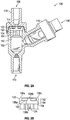
FIG. 2A illustrates a front view of an embodiment of a passive restart Y-site in an open configuration in accordance with aspects of the present disclosure. -
FIG. 2B illustrates a sectional view of portion of the passive restart Y-site ofFIG. 2A . -
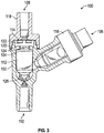
FIG. 3 illustrates a front view of an embodiment of a passive restart Y-site in a first configuration in accordance with aspects of the present disclosure. -
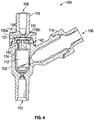
FIG. 4 illustrates a sectional view of an embodiment of a passive restart Y-site in a second configuration in accordance with aspects of the present disclosure. -
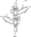
FIG. 5 illustrates a sectional view of an embodiment of a passive restart Y-site in a second configuration in accordance with aspects of the present disclosure. - In the following detailed description, specific details are set forth to provide an understanding of the subject technology. It will be apparent, however, to one ordinarily skilled in the art that the subject technology may be practiced without some of these specific details. In other instances, well-known structures and techniques have not been shown in detail so as not to obscure the subject technology.
- A phrase such as "an aspect" does not imply that such aspect is essential to the subject technology or that such aspect applies to all configurations of the subject technology. A disclosure relating to an aspect may apply to all configurations, or one or more configurations. An aspect may provide one or more examples of the disclosure. A phrase such as "an aspect" may refer to one or more aspects and vice versa. A phrase such as "an embodiment" does not imply that such embodiment is essential to the subject technology or that such embodiment applies to all configurations of the subject technology. A disclosure relating to an embodiment may apply to all embodiments, or one or more embodiments. An embodiment may provide one or more examples of the disclosure. A phrase such as "an embodiment" may refer to one or more embodiments and vice versa. A phrase such as "a configuration" does not imply that such configuration is essential to the subject technology or that such configuration applies to all configurations of the subject technology. A disclosure relating to a configuration may apply to all configurations, or one or more configurations. A configuration may provide one or more examples of the disclosure. A phrase such as "a configuration" may refer to one or more configurations and vice versa.
- The present disclosure relates to a passive restart Y-site for use in medical infusion therapy.
FIG. 1 illustrates a passive restart Y-site 100 fluidly coupled to aprimary fluid source 402 and asecondary fluid source 404. The passive restart Y-site 100 is configured to receive and control delivery of theprimary fluid 402 and thesecondary fluid 404 to a patient (not shown). In some instances, the fluid is directed through an infusion pump (also not shown) prior to being directed to the patient. - Referring to
FIGS. 2A-3 , the passive restart Y-site 100 comprises abody 102 forming achamber 104, two or more flow ports where fluid may enter thechamber 104, and a port where fluid may exit thechamber 104. In some embodiments, thebody 102 comprises a port where aprimary fluid 402 may enter thebody 102, a port where asecondary fluid 404 may enter thebody 102, and a port for either fluid to exit thebody 102. In a preferred embodiment, thebody 102 comprises atop port 108 and abottom port 110 with thechamber 104 therebetween. Aside port 106 is fluidly connected to thechamber 104 between thetop port 108 andbottom port 110. Aprimary fluid 402 may enter thechamber 104 from thetop port 108, while asecondary fluid 404 may enter thechamber 104 from theside port 106. Fluid that enters thechamber 104 from either port may exit the chamber from thebottom port 110. A fluid source may be coupled with thetop port 108 orside port 106 using a fluid fitting such as a luer-type fitting. In a preferred embodiment, theside port 106 comprises aneedleless access valve 116. - Flow of two or more fluids to a patient is passively controlled within the
body 102. More specifically, flow of aprimary fluid 402 from thetop port 108 into thechamber 104 is reduced or halted upon the fluid within thechamber 104 exceeding a filling threshold. The filling threshold may be exceeded as a result of aprimary fluid 402 entering thechamber 104 from thetop port 108 or asecondary fluid 404 entering thechamber 104 from theside port 106. When the fluid within thechamber 104 fills to exceed the filling threshold, the flow of theprimary fluid 402 from thetop port 108 into thechamber 104 is reduced or halted by movement of avalve 114 andfloat 112. When the fluid level within thechamber 104 drains through the exit orbottom port 110, the fluid level within thechamber 104 will decrease. When the fluid level is below the filling threshold, for example, when the secondary fluid flow 404 from theside port 106 into thechamber 104 is reduced or ceases, thevalve 114 and float 112 follow the fluid level and move to allow theprimary fluid 402 to once again flow into thechamber 104. - The Y-site operates to prioritize communication of the fluid to the patient. In some embodiments, the Y-site is designed to communicate the second fluid through the chamber before communicating the entire reservoir of the first fluid. It prioritizes what is communicated through the chamber by halting flow of the primary fluid until the secondary fluid has been communicated through the chamber. By halting flow of the
primary fluid 402 upon introduction of thesecondary fluid 404, complete delivery of thesecondary fluid 404 to the patient may be assured before flow of theprimary fluid 402 is resumed. When flow of theprimary fluid 402 is partially halted, combinedsecondary fluid 404 andprimary fluid 402 may be delivered to the patient in a specific ratio. - The
body 102 may be any shape, including a cylinder or elongate having a cross-section that is a sphere, square, or rectangle. In a preferred embodiment, the body is cylindrically shaped. Thebody 102 may be composed of any rigid material such as a polycarbonate, acrylonitrile butadiene styrene (ABS), or polystyrene. Thebody 102 andchamber 104 may be a size that achieves the desired flow rate and volume. For example, thechamber 104 volume may be selected to achieve a specific flow rate or to retainspecific float 112 orvalve 114 sizes. Thebody 102 may further comprise a bleed off valve or filter (not shown), such as a hydrophobic filter, to allow air to escape from within thechamber 104. In some embodiments, thebody 102 comprises a lens or other visual indicator (not shown) of flow movement or float position within thebody 102. - In a preferred embodiment the
body 102 has atop port 108, abottom port 110 opposite thetop port 108, and aside port 106 disposed between thetop port 108 andbottom port 110. However, the ports may be oriented in any location on thebody 102. For example, thetop port 108 andside port 106 may be disposed at the top of thebody 102 with each port having a respective flow path through thebody 102 and into thechamber 104. In some embodiments, any of the ports may be formed as acap 118 coupled to thebody 102. In a preferred embodiment, thecap 118 is removably coupled to the body, thereby providing access to thechamber 104. In some embodiments, thecap 118 is adjustable to reduce or enlarge thechamber 104 volume, alter fluid flow through thechamber 104, or vary the buoyancy of thefloat 112. - Referring to
FIG. 2B , avalve guide 122 may be disposed in thechamber 104 proximate thetop port 108. Thevalve guide 122 comprises andupper portion 132 and alower portion 134. The perimeter of theupper portion 132 comprises a plurality of fingers (e.g., 136a, 136b, 136c) that extend from thelower portion 134. Adjacent fingers, for example 136a and 136b, have opposingedges lower edge 140 is formed between the opposingedges lower portion 134. Opposingedges lower edge 140 create a peripheral opening through the perimeter of theupper portion 132. Referring to the embodiment illustrated inFIG. 4 , thelower potion 134 comprises one or more longitudinally orientedapertures 142 disposed through the cross-section of thevalve guide 122. In some embodiments, theapertures 142 are offset from the central axis of thevalve guide 122. - A
valve 114 may be disposed in thechamber 104 proximate thetop port 108 such that thevalve 114 is positioned between thefingers upper portion 132. Thevalve 114 may be cylindrically shaped with a convex and concaved surface, and wherein a circumferential edge of the concaved surface is engaged or is configured to engage with alower portion 134 of thevalve guide 122. In an open configuration, a fluid flow from thetop port 108 may enter thechamber 104 from anaperture 144 through thecap 118. The fluid may then pass over the convex surface and around the circumferential edge of thevalve 114. The peripheral openings through the perimeter of theupper portion 132 allows the fluid to flow beneath the concave surface of thevalve 114 and through theapertures 142 of thelower portion 134. - The
valve 114 is configured to occlude theaperture 144 of thetop port 108 upon fluid within thechamber 104 exceeding a filling threshold. In some embodiments, thevalve 114 only partially occludes thetop port 108 upon exceeding a filling threshold, allowing flow from both thetop port 108 andside port 106 into thechamber 104. Preferably, the shape of thevalve 114 is a large disk having a broad surface, wherein thevalve 114 is activated by fluid pressure from asecondary fluid 404 flow upon the broad surface. In some embodiments, thevalve 114 is shaped as a cone, sphere, or any other shape that may be activated by fluid to occlude thetop port 108. In some embodiments, thevalve 114 is elastically deformed when activated by the presence of fluid pressure within thechamber 104. - The
valve 114 may be fabricated from a malleable rubber, silicone, plastic, or thermoplastic elastomer. Thevalve 114 dimensions may be selected to achieve activation or movement of thevalve 114 upon a specific fluid pressure. For example, avalve 114 thickness may be selected to partially or fully occlude thetop port 108 in response to a specified fluid level or fluid pressure. In some embodiments, thevalve 114 partially occludes thetop port 108 at a first fluid pressure, and then fully occludes thetop port 108 at a second fluid pressure. Avalve seat 120, configured to retain thevalve 114, may be disposed in thebody 102 proximate thetop port 108. A first side of thevalve seat 120 may be formed as a circumferential ridge in thechamber 104 while the second side may be formed by thetop port 108. In some embodiments, the second side of the valve seat may be an arcuate surface. Avalve guide 122 may also be disposed in thechamber 104 proximal to thetop port 108. In some embodiments, thevalve seat 102 is configured to retain thevalve guide 122 andvalve 114. Thevalve guide 122 may be shaped as a basket to retain and guide thevalve 114 in thechamber 104. Thevalve guide 122 may have one or more aperture through its cross-section to allow fluid flow through thevalve guide 122. Preferably, thevalve guide 122 is composed of a rigid material to protect against unintentional deformation of thevalve 114. - The
float 112 may be disposed in thechamber 104 between thevalve 114 andbottom port 110. Thefloat 112 comprises specific buoyancy and is configured to move within thechamber 104 between thetop port 108 andbottom port 110 in response to fluid flow. Thefloat 112 may include aprotrusion 124 that extends partially toward thevalve 114. When thefloat 112 rises, theprotrusion 124 may engage thevalve 114, assuring thevalve 114 remains in the activated position. In some embodiments, theprotrusion 124 andvalve 114 are coupled, whereby theprotrusion 124 andvalve 114 move in unison within thechamber 104. An aperture through thevalve guide 122 allows theprotrusion 124 to pass through thevalve guide 122 unobstructed. In some embodiments, thefloat 112 comprises radial protrusions or grooves on an outer surface to allow fluid flow past thefloat 112 when the float is in contact with a port. For example, fluid may continue to exit thechamber 104 when the float is in a lowered position that would otherwise occlude thebottom port 110. In some embodiments thefloat 112 orchamber 104 comprises anannular ring 126 or seat such that thebottom port 110 becomes occluded when thefloat 112 is in a lowermost position, thereby preventing air from passing through thechamber 104 to the patient. - The
float 112 may comprise specific buoyancy such that a specific fluid level within the chamber causes thefloat 112 to rise or lower in the chamber. The float may be solid or hollow, and may comprise air or foam. Preferably, the material used to fabricate thefloat 112 will not degrade in the particular environment. In some embodiments, all or a portion of thefloat 112 is coated with a non-degrading material. The buoyancy characteristics of thefloat 112 may be varied by rotation of a dial or selector. For example, thefloat 112 may be configured as two portions coupled together. The two portions of thefloat 112 may be rotated to increase or decrease the volume within thefloat 112. In some embodiments, the buoyancy of thefloat 112 is varied by altering the interior volume of thefloat 112. For example, thefloat 112 may be configured with an inner bladder fillable through a valve in a surface of thefloat 112. - During fluid flow from the
top port 108 thevalve 114 would remain in an open or deactivated position, and thefloat 112 would remain between thevalve 114 andbottom port 110, thereby allowing fluid flow from thetop port 108 to enter thechamber 104 and exit from thebottom port 110. Upon fluid within thechamber 104 exceeding a filling threshold, such as by introduction of a fluid flow from theside port 106 or from thetop port 108, the fluid would cause thevalve 114 to be activated and occlude thetop port 108. Additionally, thefloat 112 may rise and engage thevalve 114, assuring thevalve 114 remains activated. In this occluded configuration, fluid that remains in thechamber 104, and fluid flow from theside port 106, would enter thechamber 104 and exit from thebottom port 110. Once the fluid drains from thebottom port 110, thefloat 112 will drop with the fluid level in thechamber 104, and reopen thetop port 108, thereby again permitting flow through thetop port 108 to enter thechamber 104. This is one example of how the Y-site passively stops and restarts based on the level of fluid within the chamber. - In some embodiments, the
valve 114 and float 112 are configured to partially occlude thetop port 108, allowing a combined fluid flow from thetop port 108 andside port 106 to enter thechamber 104 and exit from thebottom port 110. Upon a reduction of fluid within thechamber 104 to below the filling threshold, or a reduction or completion of fluid flow from theside port 106, an open position would be achieved. In an open position, thefloat 112 would lower and thevalve 114 would disengage or open, thereby allowing fluid flow from thetop port 108 to enter thechamber 104 and exit from thebottom port 110. - In some embodiments, the
float 112 comprises two ormore protrusions 124 configured to engage avalve 114. In some embodiments thebody 102 comprises two ormore chambers 104 and floats 112, allowing for two or moreprimary fluids 402 orsecondary fluids 404 to be coupled with the passive restart Y-site 100 as illustrated inFIG. 5 . In some embodiments where multipleprimary fluids 402 orsecondary fluids 404 are coupled to the passive restart Y-site 100, a selector may be utilized to determine the sequence of primary or secondary flows into thechamber 104. - The foregoing description is provided to enable a person skilled in the art to practice the various configurations described herein. While the subject technology has been particularly described with reference to the various figures and configurations, it should be understood that these are for illustration purposes only and should not be taken as limiting the scope of the subject technology.
- There may be many other ways to implement the subject technology. Various functions and elements described herein may be partitioned differently from those shown without departing from the scope of the subject technology. Various modifications to these configurations will be readily apparent to those skilled in the art, and generic principles defined herein may be applied to other configurations. Thus, many changes and modifications may be made to the subject technology, by one having ordinary skill in the art, without departing from the scope of the subject technology.
- As used herein, the phrase "at least one of' preceding a series of items, with the term "and" or "or" to separate any of the items, modifies the list as a whole, rather than each member of the list (i.e., each item). The phrase "at least one of' does not require selection of at least one of each item listed; rather, the phrase allows a meaning that includes at least one of any one of the items, and/or at least one of any combination of the items, and/or at least one of each of the items. By way of example, the phrases "at least one of A, B, and C" or "at least one of A, B, or C" each refer to only A, only B, or only C; any combination of A, B, and C; and/or at least one of each of A, B, and C.
- Furthermore, to the extent that the term "include," "have," or the like is used in the description or the claims, such term is intended to be inclusive in a manner similar to the term "comprise" as "comprise" is interpreted when employed as a transitional word in a claim. The word "exemplary" is used herein to mean "serving as an example, instance, or illustration." Any embodiment described herein as "exemplary" is not necessarily to be construed as preferred or advantageous over other embodiments.
- A reference to an element in the singular is not intended to mean "one and only one" unless specifically stated, but rather "one or more." The term "some" refers to one or more. All structural and functional equivalents to the elements of the various configurations described throughout this disclosure that are known or later come to be known to those of ordinary skill in the art are expressly incorporated herein by reference and intended to be encompassed by the subject technology. Moreover, nothing disclosed herein is intended to be dedicated to the public regardless of whether such disclosure is explicitly recited in the above description.
- While certain aspects and embodiments of the subject technology have been described, these have been presented by way of example only, and are not intended to limit the scope of the subject technology. Indeed, the novel methods and systems described herein may be embodied in a variety of other forms without departing from the spirit thereof. The accompanying claims and their equivalents are intended to cover such forms or modifications as would fall within the scope and spirit of the subject technology.
- Described herein are at least the following concepts:
- Concept 1. A fluid delivery Y-site device comprising:
- a chamber fluidly coupled between a primary flow port and an exit flow port;
- a secondary flow port fluidly coupled to the chamber, the secondary flow port configured to conduct fluid to the chamber; and
- a valve positioned adjacent the primary flow port, the valve configured to move between an occluding configuration and an open configuration, based on a level of fluid within the chamber, such that the valve controls fluid flow through the primary flow port and into the chamber.
- Concept 2. The device of concept 1, further comprising a float disposed within the chamber between the valve and the exit flow port, the float configured to (i) move within the chamber and (ii) move the valve to the occluding configuration when the level of fluid within the chamber exceeds a filling threshold.
- Concept 3. The device of concept 2, wherein the float is configured to permit transition of the valve to the open configuration when the level of fluid within the chamber is below the filling threshold.
- Concept 4. The device of concept 2, wherein the float is configured to occlude the exit flow port when the level of fluid within the chamber is below a draining threshold.
- Concept 5. The device of concept 4, further comprising an annular ring disposed proximal to the exit flow port, the float being configured to engage the annular ring, such that the engagement between the float and the ring restricts air from exiting the chamber through the exit flow port.
- Concept 6. The device of concept 1, further comprising a valve seat formed in the chamber proximate the primary flow port.
- Concept 7. The device of concept 1, further comprising a valve guide disposed in the chamber proximate the primary flow port, the valve disposed at least partially within the valve guide, and the valve guide configured to guide the valve between the occluding configuration and the open configuration.
- Concept 8. The device of concept 1, wherein the valve is a disk having a convex surface that is configured to face the primary flow port and a concave surface that is configured to face away from the primary flow port, the disk being configured to be elastically deformed based on the level of fluid within the chamber.
- Concept 9. The device of concept 1, wherein the secondary flow port comprises a needleless access valve.
- Concept 10. The device of concept 1, wherein the secondary flow port is connected to the chamber at an angle relative of between about 20 degrees and about 60 degrees from a longitudinal axis of the chamber.
- Concept 11. The device of concept 2, wherein the float comprises a protrusion extending from the float toward the valve, such that the protrusion engages the valve when the float moves the valve to the occluding configuration.
- Concept 12. The device of concept 11, wherein the protrusion extends through the valve guide and engages the valve when the level of fluid within the chamber exceeds the filling threshold.
- Concept 13. The device of concept 2, wherein the float comprises variable interior volume, such that buoyancy of the float can be adjusted.
- Concept 14. The device of concept 2, further comprising an indicator that provides visual indication that the float has moved the valve to the occluding configuration.
- Concept 15. The device of concept 14, wherein the indicator comprises a transparent window in a wall of the chamber, the transparent window forming a lens.
- Concept 16. The device of concept 1, wherein the chamber comprises an air valve configured to release air from within the chamber.
- Concept 17. A method of controlling fluid through a Y-site device, comprising:
- providing a chamber fluidly coupled between a primary flow port and an exit flow port;
- providing a secondary flow port fluidly coupled to the chamber, the secondary flow port configured to conduct fluid to the chamber;
- providing a valve positioned adjacent the primary flow port; and
- moving, based on a level of fluid within the chamber, the valve between an occluding configuration and an open configuration, such that the valve controls fluid flow through the primary flow port and into the chamber.
- Concept 18. The method of concept 17, wherein the valve is moved by a float disposed within the chamber between the valve and the exit flow port, the float moving the valve to the occluding configuration when the level of fluid within the chamber exceeds a filling threshold.
- Concept 19. The method of concept 18, further comprising engaging the valve with the float when moving the valve to the occluding configuration and disengaging the float and the valve when the level of fluid is below the filling threshold.
- Concept 20. The method of concept 18, further comprising occluding the exit flow port when the level of fluid within the chamber is below a draining threshold.
Claims (15)
- A fluid delivery Y-site device comprising:a primary flow port, an exit flow port, and a chamber fluidly coupled between the primary flow port and the exit flow port;a secondary flow port fluidly coupled to the chamber;a valve guide having a lower portion that extends into the chamber, between the primary flow port and the exit flow port, and an upper portion that extends from the lower portion toward the primary flow port; anda valve positioned in the chamber, between the primary flow port and the lower portion of the valve guide, wherein the lower portion of the valve guide is configured to resist movement of the valve toward the exit flow port.
- The fluid delivery Y-site device of Claim 1, further comprising a float positioned within the chamber between the valve and the exit flow port, wherein the float is configured to move to engage against the valve based on a level of fluid in the chamber.
- The fluid delivery Y-site device of Claim 2, wherein the float is moveable, independent of the valve, based on a level of fluid within the chamber.
- The fluid delivery Y-site device of Claim 2, wherein the float comprises a protrusion that extends in a direction toward the valve.
- The fluid delivery Y-site device of Claim 1, wherein the secondary flow port is positioned between the lower portion of the valve guide and the exit flow port.
- The fluid delivery Y-site device of Claim 1, wherein the upper portion of the valve guide comprises a plurality of fingers that extend from the lower portion of the valve guide toward the primary flow port.
- The fluid delivery Y-site device of Claim 6, wherein the valve is positioned between the plurality of fingers and the lower portion of the valve guide.
- The fluid delivery Y-site device of Claim 6, wherein an opening extends through the upper portion of the valve guide, between adjacent fingers of the plurality of fingers.
- The fluid delivery Y-site device of Claim 1, wherein a passage extends through the lower portion of the valve guide.
- The fluid delivery Y-site device of Claim 1, wherein the valve comprises a convex upper surface configured to engage against the primary flow port and a concave lower surface configured to engage against the lower portion of the valve guide.
- The fluid delivery Y-site device of Claim 1, wherein the valve comprises an occluding configuration, wherein an upper surface of the valve is engaged against the primary flow port, and an open configuration, wherein a lower surface of the valve is engaged against the lower portion of the valve guide.
- The fluid delivery Y-site device of Claim 1, wherein the secondary flow port is fluidly coupled to the chamber between the valve and the exit flow port.
- The fluid delivery Y-site device of Claim 1, wherein valve guide is composed of a rigid material.
- The fluid delivery Y-site device of Claim 1, wherein the valve comprises any of a malleable rubber, a silicon, a plastic, and a thermoplastic elastomer.
- The fluid delivery Y-site device of Claim 1, wherein the valve elastically deformed when activated by a presence of a fluid pressure within the chamber.
Applications Claiming Priority (3)
| Application Number | Priority Date | Filing Date | Title |
|---|---|---|---|
| US14/319,948 US9724464B2 (en) | 2014-06-30 | 2014-06-30 | Passive restart Y-site |
| EP15735782.3A EP3160542B1 (en) | 2014-06-30 | 2015-06-17 | Passive restart y-site |
| PCT/US2015/036289 WO2016003654A1 (en) | 2014-06-30 | 2015-06-17 | Passive restart y-site |
Related Parent Applications (2)
| Application Number | Title | Priority Date | Filing Date |
|---|---|---|---|
| EP15735782.3A Division-Into EP3160542B1 (en) | 2014-06-30 | 2015-06-17 | Passive restart y-site |
| EP15735782.3A Division EP3160542B1 (en) | 2014-06-30 | 2015-06-17 | Passive restart y-site |
Publications (1)
| Publication Number | Publication Date |
|---|---|
| EP3909622A1 true EP3909622A1 (en) | 2021-11-17 |
Family
ID=53525261
Family Applications (2)
| Application Number | Title | Priority Date | Filing Date |
|---|---|---|---|
| EP21179921.8A Pending EP3909622A1 (en) | 2014-06-30 | 2015-06-17 | Passive restart y-site |
| EP15735782.3A Active EP3160542B1 (en) | 2014-06-30 | 2015-06-17 | Passive restart y-site |
Family Applications After (1)
| Application Number | Title | Priority Date | Filing Date |
|---|---|---|---|
| EP15735782.3A Active EP3160542B1 (en) | 2014-06-30 | 2015-06-17 | Passive restart y-site |
Country Status (9)
| Country | Link |
|---|---|
| US (4) | US9724464B2 (en) |
| EP (2) | EP3909622A1 (en) |
| JP (2) | JP6730939B2 (en) |
| CN (2) | CN106456873B (en) |
| AU (2) | AU2015284634B2 (en) |
| BR (2) | BR112016030631B1 (en) |
| CA (1) | CA2953115C (en) |
| MX (1) | MX2016016873A (en) |
| WO (1) | WO2016003654A1 (en) |
Families Citing this family (9)
| Publication number | Priority date | Publication date | Assignee | Title |
|---|---|---|---|---|
| JP7176834B2 (en) | 2013-12-11 | 2022-11-22 | アイシーユー・メディカル・インコーポレーテッド | check valve |
| US9724464B2 (en) * | 2014-06-30 | 2017-08-08 | Carefusion 303, Inc. | Passive restart Y-site |
| USD786427S1 (en) | 2014-12-03 | 2017-05-09 | Icu Medical, Inc. | Fluid manifold |
| USD793551S1 (en) | 2014-12-03 | 2017-08-01 | Icu Medical, Inc. | Fluid manifold |
| US10413662B2 (en) | 2015-05-14 | 2019-09-17 | Carefusion 303, Inc. | Priming apparatus and method |
| AU2017212349B2 (en) * | 2016-01-27 | 2021-03-25 | Carefusion 303, Inc. | Intermittent infusion device |
| CN109010987B (en) * | 2018-08-03 | 2020-10-23 | 中国人民解放军陆军军医大学第一附属医院 | Infusion device for monitoring room |
| US20200222681A1 (en) * | 2019-01-14 | 2020-07-16 | Becton, Dickinson And Company | Needleless access connector facilitating instrument delivery to a catheter assembly |
| CN113521444B (en) * | 2021-07-15 | 2022-06-21 | 陕西省人民医院 | Continuous infusion apparatus with acupuncture type sequential channel switching |
Citations (2)
| Publication number | Priority date | Publication date | Assignee | Title |
|---|---|---|---|---|
| US4256103A (en) * | 1978-10-11 | 1981-03-17 | James Paxinos | Automatic sequential fluid flow apparatus |
| CN102743809A (en) * | 2012-07-14 | 2012-10-24 | 汤园园 | Intermittent transfusion set |
Family Cites Families (25)
| Publication number | Priority date | Publication date | Assignee | Title |
|---|---|---|---|---|
| US2784733A (en) * | 1954-10-08 | 1957-03-12 | Baxter Don Inc | Check valve for parenteral solutions |
| US4005710A (en) * | 1975-02-12 | 1977-02-01 | Abbott Laboratories | Parenteral apparatus with one-way valve |
| US4449976A (en) | 1981-05-21 | 1984-05-22 | Baxter Travenol Laboratories, Inc. | Device for preserving continuity of intravenous flow |
| US4563173A (en) * | 1983-04-19 | 1986-01-07 | National Biomedical Research Foundation | Pump-actuated sequencing valve and system |
| US5279557A (en) * | 1993-05-24 | 1994-01-18 | Lomick Joe B | Multiple chamber IV delivery device |
| CN2201947Y (en) * | 1994-06-13 | 1995-06-28 | 彭元济 | Automatic-closing medical transfusion system |
| US6213986B1 (en) | 1995-09-29 | 2001-04-10 | Appro Healthcare, Inc. | Liquid flow rate control device |
| US5839466A (en) * | 1996-04-29 | 1998-11-24 | Dutter; Marshall | Automatic watering device |
| JPH11183283A (en) * | 1997-12-16 | 1999-07-09 | Masaji Haraguchi | U-tube differential pressure gauge |
| JPH11183282A (en) | 1997-12-22 | 1999-07-09 | Osaka Gas Co Ltd | Apparatus and method for measuring dynamic pressure of fluid containing slurry |
| JP4263328B2 (en) * | 2000-01-24 | 2009-05-13 | シエーリング アクチエンゲゼルシャフト | Injection tool |
| US6485454B1 (en) | 2000-10-13 | 2002-11-26 | Edward Yang | Automatic infusion set for continuously infusing liquid medicine of double bottles |
| US6818420B2 (en) * | 2002-02-27 | 2004-11-16 | Biosource International, Inc. | Methods of using FET labeled oligonucleotides that include a 3′-5′ exonuclease resistant quencher domain and compositions for practicing the same |
| CN2556437Y (en) * | 2002-07-16 | 2003-06-18 | 富斯特阿赛特斯公司 | Float valve |
| KR100578001B1 (en) | 2004-05-03 | 2007-11-30 | (주)이화바이오메딕스 | Regulator for quantity of injection |
| US7600530B2 (en) * | 2004-08-09 | 2009-10-13 | Medegen, Inc. | Connector with check valve and method of use |
| US9352080B2 (en) * | 2005-10-13 | 2016-05-31 | Analytica Limited | Burette |
| US7865979B2 (en) * | 2007-07-10 | 2011-01-11 | Hand Douglas P | Flush valve structure for a toilet tank |
| US9205248B2 (en) | 2010-02-24 | 2015-12-08 | Becton, Dickinson And Company | Safety Drug delivery connectors |
| US8366658B2 (en) | 2010-05-06 | 2013-02-05 | Becton, Dickinson And Company | Systems and methods for providing a closed venting hazardous drug IV set |
| MY164744A (en) * | 2010-10-29 | 2018-01-30 | Hian Khim Francis Then | Intravenous fluid delivery system |
| CN102727957B (en) | 2012-06-06 | 2014-05-14 | 唐敏峰 | Multi-bottle automatic continuous penetrating venous infusion apparatus |
| US9545508B2 (en) | 2012-06-12 | 2017-01-17 | Carefusion 303, Inc. | Drip chamber |
| CN102973997B (en) | 2012-12-28 | 2014-04-30 | 唐敏峰 | Multifunctional venous infusion apparatus |
| US9724464B2 (en) * | 2014-06-30 | 2017-08-08 | Carefusion 303, Inc. | Passive restart Y-site |
-
2014
- 2014-06-30 US US14/319,948 patent/US9724464B2/en active Active
-
2015
- 2015-06-17 BR BR112016030631-7A patent/BR112016030631B1/en active IP Right Grant
- 2015-06-17 EP EP21179921.8A patent/EP3909622A1/en active Pending
- 2015-06-17 BR BR122020014254-5A patent/BR122020014254B1/en active IP Right Grant
- 2015-06-17 WO PCT/US2015/036289 patent/WO2016003654A1/en active Application Filing
- 2015-06-17 CN CN201580035512.4A patent/CN106456873B/en active Active
- 2015-06-17 AU AU2015284634A patent/AU2015284634B2/en active Active
- 2015-06-17 JP JP2016575744A patent/JP6730939B2/en active Active
- 2015-06-17 CA CA2953115A patent/CA2953115C/en active Active
- 2015-06-17 MX MX2016016873A patent/MX2016016873A/en unknown
- 2015-06-17 CN CN202010263694.3A patent/CN111437454B/en active Active
- 2015-06-17 EP EP15735782.3A patent/EP3160542B1/en active Active
-
2017
- 2017-07-28 US US15/662,985 patent/US10335544B2/en active Active
-
2019
- 2019-05-28 US US16/424,288 patent/US11383033B2/en active Active
- 2019-08-23 AU AU2019219841A patent/AU2019219841B2/en active Active
-
2020
- 2020-07-03 JP JP2020115661A patent/JP6974545B2/en active Active
-
2022
- 2022-07-08 US US17/860,801 patent/US20220339354A1/en active Pending
Patent Citations (2)
| Publication number | Priority date | Publication date | Assignee | Title |
|---|---|---|---|---|
| US4256103A (en) * | 1978-10-11 | 1981-03-17 | James Paxinos | Automatic sequential fluid flow apparatus |
| CN102743809A (en) * | 2012-07-14 | 2012-10-24 | 汤园园 | Intermittent transfusion set |
Also Published As
| Publication number | Publication date |
|---|---|
| AU2015284634B2 (en) | 2019-06-27 |
| CN106456873B (en) | 2020-04-28 |
| US9724464B2 (en) | 2017-08-08 |
| EP3160542B1 (en) | 2021-12-22 |
| JP2020171746A (en) | 2020-10-22 |
| BR112016030631B1 (en) | 2022-11-22 |
| US20170326295A1 (en) | 2017-11-16 |
| AU2019219841B2 (en) | 2021-05-20 |
| CN111437454A (en) | 2020-07-24 |
| US20220339354A1 (en) | 2022-10-27 |
| US20150374910A1 (en) | 2015-12-31 |
| WO2016003654A1 (en) | 2016-01-07 |
| MX2016016873A (en) | 2017-07-14 |
| CN106456873A (en) | 2017-02-22 |
| JP6974545B2 (en) | 2021-12-01 |
| AU2019219841A1 (en) | 2019-09-12 |
| JP2017520321A (en) | 2017-07-27 |
| CA2953115A1 (en) | 2016-01-07 |
| BR112016030631A2 (en) | 2017-08-22 |
| BR122020014254B1 (en) | 2023-03-07 |
| US10335544B2 (en) | 2019-07-02 |
| CN111437454B (en) | 2022-07-19 |
| AU2015284634A1 (en) | 2017-01-12 |
| US11383033B2 (en) | 2022-07-12 |
| CA2953115C (en) | 2023-10-24 |
| US20190275244A1 (en) | 2019-09-12 |
| JP6730939B2 (en) | 2020-07-29 |
| EP3160542A1 (en) | 2017-05-03 |
Similar Documents
| Publication | Publication Date | Title |
|---|---|---|
| US11383033B2 (en) | Passive restart Y-site | |
| US11439751B2 (en) | Passive start drip chamber | |
| US20160331937A1 (en) | Catheter devices with valves and related methods | |
| KR20200001669U (en) | Drip chamber with air shut-off function |
Legal Events
| Date | Code | Title | Description |
|---|---|---|---|
| PUAI | Public reference made under article 153(3) epc to a published international application that has entered the european phase |
Free format text: ORIGINAL CODE: 0009012 |
|
| STAA | Information on the status of an ep patent application or granted ep patent |
Free format text: STATUS: THE APPLICATION HAS BEEN PUBLISHED |
|
| AC | Divisional application: reference to earlier application |
Ref document number: 3160542 Country of ref document: EP Kind code of ref document: P |
|
| AK | Designated contracting states |
Kind code of ref document: A1 Designated state(s): AL AT BE BG CH CY CZ DE DK EE ES FI FR GB GR HR HU IE IS IT LI LT LU LV MC MK MT NL NO PL PT RO RS SE SI SK SM TR |
|
| B565 | Issuance of search results under rule 164(2) epc |
Effective date: 20210924 |
|
| STAA | Information on the status of an ep patent application or granted ep patent |
Free format text: STATUS: REQUEST FOR EXAMINATION WAS MADE |
|
| 17P | Request for examination filed |
Effective date: 20220505 |
|
| RBV | Designated contracting states (corrected) |
Designated state(s): AL AT BE BG CH CY CZ DE DK EE ES FI FR GB GR HR HU IE IS IT LI LT LU LV MC MK MT NL NO PL PT RO RS SE SI SK SM TR |