EP3909293B1 - Verfahren und vorrichtung zur steuerung von benutzergerätekontext in einem drahtloskommunikationssystem - Google Patents
Verfahren und vorrichtung zur steuerung von benutzergerätekontext in einem drahtloskommunikationssystem Download PDFInfo
- Publication number
- EP3909293B1 EP3909293B1 EP20756319.8A EP20756319A EP3909293B1 EP 3909293 B1 EP3909293 B1 EP 3909293B1 EP 20756319 A EP20756319 A EP 20756319A EP 3909293 B1 EP3909293 B1 EP 3909293B1
- Authority
- EP
- European Patent Office
- Prior art keywords
- context
- gnb
- node
- message
- update
- Prior art date
- Legal status (The legal status is an assumption and is not a legal conclusion. Google has not performed a legal analysis and makes no representation as to the accuracy of the status listed.)
- Active
Links
Images


Classifications
-
- H—ELECTRICITY
- H04—ELECTRIC COMMUNICATION TECHNIQUE
- H04W—WIRELESS COMMUNICATION NETWORKS
- H04W8/00—Network data management
- H04W8/22—Processing or transfer of terminal data, e.g. status or physical capabilities
- H04W8/24—Transfer of terminal data
-
- H—ELECTRICITY
- H04—ELECTRIC COMMUNICATION TECHNIQUE
- H04W—WIRELESS COMMUNICATION NETWORKS
- H04W36/00—Hand-off or reselection arrangements
- H04W36/0005—Control or signalling for completing the hand-off
- H04W36/0011—Control or signalling for completing the hand-off for data sessions of end-to-end connection
- H04W36/0022—Control or signalling for completing the hand-off for data sessions of end-to-end connection for transferring data sessions between adjacent core network technologies
-
- H—ELECTRICITY
- H04—ELECTRIC COMMUNICATION TECHNIQUE
- H04W—WIRELESS COMMUNICATION NETWORKS
- H04W24/00—Supervisory, monitoring or testing arrangements
- H04W24/02—Arrangements for optimising operational condition
-
- H—ELECTRICITY
- H04—ELECTRIC COMMUNICATION TECHNIQUE
- H04W—WIRELESS COMMUNICATION NETWORKS
- H04W36/00—Hand-off or reselection arrangements
- H04W36/0005—Control or signalling for completing the hand-off
- H04W36/0011—Control or signalling for completing the hand-off for data sessions of end-to-end connection
- H04W36/0033—Control or signalling for completing the hand-off for data sessions of end-to-end connection with transfer of context information
-
- H—ELECTRICITY
- H04—ELECTRIC COMMUNICATION TECHNIQUE
- H04W—WIRELESS COMMUNICATION NETWORKS
- H04W36/00—Hand-off or reselection arrangements
- H04W36/0005—Control or signalling for completing the hand-off
- H04W36/0055—Transmission or use of information for re-establishing the radio link
- H04W36/0069—Transmission or use of information for re-establishing the radio link in case of dual connectivity, e.g. decoupled uplink/downlink
- H04W36/00698—Transmission or use of information for re-establishing the radio link in case of dual connectivity, e.g. decoupled uplink/downlink using different RATs
-
- H—ELECTRICITY
- H04—ELECTRIC COMMUNICATION TECHNIQUE
- H04W—WIRELESS COMMUNICATION NETWORKS
- H04W8/00—Network data management
- H04W8/02—Processing of mobility data, e.g. registration information at HLR [Home Location Register] or VLR [Visitor Location Register]; Transfer of mobility data, e.g. between HLR, VLR or external networks
- H04W8/08—Mobility data transfer
-
- H—ELECTRICITY
- H04—ELECTRIC COMMUNICATION TECHNIQUE
- H04W—WIRELESS COMMUNICATION NETWORKS
- H04W88/00—Devices specially adapted for wireless communication networks, e.g. terminals, base stations or access point devices
- H04W88/08—Access point devices
- H04W88/085—Access point devices with remote components
-
- H—ELECTRICITY
- H04—ELECTRIC COMMUNICATION TECHNIQUE
- H04W—WIRELESS COMMUNICATION NETWORKS
- H04W92/00—Interfaces specially adapted for wireless communication networks
- H04W92/16—Interfaces between hierarchically similar devices
- H04W92/20—Interfaces between hierarchically similar devices between access points
Definitions
- the disclosure relates to a method and apparatus for controlling user equipment (UE) context between a plurality of nodes.
- UE user equipment
- the 5G communication system or pre-5G communication system is called a beyond 4G network communication system or a post long-term evolution (LTE) system.
- LTE post long-term evolution
- the 5G communication system is considered to be implemented in a mmWave band (e.g., 60 GHz band).
- hybrid frequency shift key (FSK) and quadrature amplitude modulation (QAM) modulation (FQAM) and sliding window superposition coding (SWSC) that are advanced coding modulation (ACM) schemes, improved filter bank multicarrier (FBMC), non-quadrature multiple access (NOMA) and sparse code multiple access (SCMA) are being developed in the 5G system.
- FSK frequency shift key
- QAM quadrature amplitude modulation
- SWSC sliding window superposition coding
- ACM advanced coding modulation
- FBMC filter bank multicarrier
- NOMA non-quadrature multiple access
- SCMA sparse code multiple access
- the Internet evolves from a human-centered connection network over which human generates and consumes information to Internet of Things (IoT) in which information is exchanged and process between distributed elements, such as things.
- IoT Internet of Things
- IoE Internet of Everything
- technical elements such as the sensing technology, wired/wireless communication and network infrastructure, service interface technology and security technology, are required. Accordingly, technologies, such as a sensor network, machine to machine (M2M) and machine type communication (MTC) for a connection between things, are recently researched.
- an intelligent Internet technology (IT) service in which a new value is created for human life by collecting and analyzing data generated from connected things may be provided.
- the IoT may be applied to fields, such as a smart home, a smart building, a smart city, a smart car or a connected car, a smart grid, health care, smart home appliances, and advanced medical services, through convergence and composition between the existing information technology (IT) and various industries.
- NR none stand-alone
- NR new radio
- EUTRA evolved universal terrestrial radio access
- EN-DC evolved universal terrestrial radio access
- an apparatus such as a terminal, performs radio access using an LTE base station as a master node and using an NR base station as a secondary node.
- a technology in which the existing protocol layers within a base station are separated and implemented into a central unit (CU) and a distributed unit (DU) has been introduced into 5G.
- Layers included in a single base station to configure a protocol stack are separated into a CU base station and a DU base station, and a fronthaul interface is configured between the CU base station and the DU base station, thereby being capable of transmitting and receiving signaling.
- TP for TS 38.473 on UE Context Management procedure (3GPP document R3-180180 ) provides a stage3 TP for UE Context Management procedures.
- 3GPP technical specification TS 38.473 V15.4.1 specifies the F1 application protocol (F1AP).
- a UE requires a change or update of UE context in the state in which the UE has accessed an LTE base station and NR base station in the EN-DC connection structure, it is necessary for a signaling operation between several nodes, such as a CU base station and DU base station separated from the LTE base station and NR base station, to be efficiently performed.
- a method performed by a distributed unit (DU) of a gNode B (gNB) in a wireless communication system is provided as defined in the appended claims.
- a method performed by a central unit (CU) of a gNode B (gNB) in a wireless communication system is provided as defined in the appended claims.
- a distributed unit (DU) of a gNode B (gNB) in a wireless communication system is provided as defined in the appended claims.
- a central unit (CU) of a gNode B (gNB) in a wireless communication system is provided as defined in the appended claims.
- an aspect of the disclosure is to provide a method of efficiently performing the update procedure of user equipment (UE) context between several nodes in a non-standalone (NSA) structure.
- UE user equipment
- a major gist of the disclosure may be slightly modified and applied to other communication systems having a similar technical background and a channel form without significantly departing from the range of the disclosure, which may be determined by a person having skilled technical knowledge in a corresponding technical field of the disclosure.
- each block of the flowchart illustrations and combinations of the blocks in the flowchart illustrations can be executed by computer program instructions.
- These computer program instructions may be mounted on the processor of a general purpose computer, a special purpose computer, or other programmable data processing apparatus, so that the instructions executed by the processor of the computer or other programmable data processing apparatus create means for executing the functions specified in the flowchart block(s).
- These computer program instructions may also be stored in computer-usable or computer-readable memory that can direct a computer or other programmable data processing equipment to function in a particular manner, such that the instructions stored in the computer-usable or computer-readable memory produce an article of manufacture including instruction means that implement the function specified in the flowchart block(s).
- the computer program instructions may also be loaded on a computer or other programmable data processing apparatus to cause a series of operations to be performed on the computer or other programmable apparatus to produce a computer-executed process, so that the instructions performing the computer or other programmable apparatus provide operations for executing the functions described in the flowchart block(s).
- each block of the flowchart illustrations may represent a portion of a module, a segment, or code, which includes one or more executable instructions for implementing a specified logical function(s). It should also be noted that in some alternative implementations, the functions noted in the blocks may occur out of order. For example, two blocks shown in succession may in fact be executed substantially concurrently, or the blocks may sometimes be executed in the reverse order, depending upon the functionality involved.
- unit means software or a hardware component, such as a field programmable gate array (FPGA) or an application-specific integrated circuit (ASIC), and the “unit” performs specific tasks.
- the “unit” may advantageously be configured to reside on an addressable storage medium and configured to operate on one or more processors.
- the "unit” may include, for example, components, such as software components, object-oriented software components, class components, and task components, processes, functions, attributes, procedures, sub-routines, segments of program code, drivers, firmware, microcode, circuitry, data, databases, data structures, tables, arrays, and variables.
- components such as software components, object-oriented software components, class components, and task components, processes, functions, attributes, procedures, sub-routines, segments of program code, drivers, firmware, microcode, circuitry, data, databases, data structures, tables, arrays, and variables.
- the functionalities provided in the components and “units” may be combined into fewer components and “units” or may be further separated into additional components and “units.”
- the components and “units” may be implemented to operation on one or more central processing units (CPUs) within a device or a security multimedia card.
- CPUs central processing units
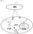
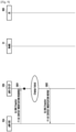
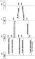
- FIG. 1 is concept view illustrating a multi-RAT dual connectivity structure according to an embodiment of the disclosure.
- a structure for EN-DC for describing an embodiment of the disclosure may be configured as illustrated in FIG. 1 .
- a connection structure for EN-DC may be a structure in which an long term evolution (LTE) base station 11, that is, a master eNB, anchors the C-plane signaling of NR, an NR base station 12 is configured as a secondary eNB, and each base station uses an evolved packet core (EPC) 1 as a core network.
- LTE long term evolution
- NR base station 12 anchors the C-plane signaling of NR
- an NR base station 12 is configured as a secondary eNB
- EPC evolved packet core
- a UE 100 may access each base station through dual connectivity using the LTE base station 11 as a master eNB and the NR base station 12 as a secondary eNB.
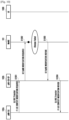
- FIG. 2 is concept view illustrating a connection between nodes and a UE according to an embodiment of the disclosure.
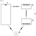
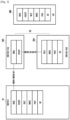
- FIG. 3 is concept view illustrating protocol stacks configured in nodes and a UE according to an embodiment of the disclosure.
- an NR base station may be configured by separating protocol stacks, included in one base station, for each function and separating the protocol stacks into a central unit (CU) and a distributed unit (DU).
- the CU and the DU may be implemented as separate base stations, and may perform respective operations of the base station.
- the CU and the DU may be described as a base station, a unit or a node.
- FIG. 2 illustrates the state in which a UE 200 according to an embodiment of the disclosure has accessed an LTE base station (RAT#1) 21 and an NR base station 22 separated into a CU base station (RAT#2-CU) 22b and a DU base station (RAT#2-DU) 22a.
- RAT#1 LTE base station
- NR base station 22 separated into a CU base station (RAT#2-CU) 22b and a DU base station (RAT#2-DU) 22a.
- the LTE base station 21 and the CU 22b of the NR base station 22 may be connected through an X2 interface (RAT#1-RAT#2-I/F).
- the CU 22b of the NR base station 22 and the DU 22a of the NR base station 22 may be connected through a fronthaul interface (RAT#2-CU-DU-I/F).
- RAT#2-CU-DU-I/F fronthaul interface
- the CU base station is described as a CU and the DU base station is described as a DU, for convenience of description.
- FIG. 3 A more detailed protocol stack is illustrated in FIG. 3 .
- RRC radio resource control
- PDCP packet data convergence protocol
- RLC radio link control
- MAC medium access control
- PHY physical
- RF radio frequency
- protocol layers may be separated based on respective functions.
- the RRC layer and PDCP layer may be configured as a CU 32b, and the RLC layer, MAC layer, PHY layer and RF functions may be configured as a DU 32a. That is, the CU 32b may perform functions corresponding to the RRC layer and PDCP layer, and the DU 32a may perform the functions of the RLC layer, the MAC layer, the PHY layer and the RF.
- all the protocol stacks of a UE 300 that configures dual connectivity with the LTE base station 31 and the NR base station 32 may be included and implemented like the LTE base station 31.
- the function of each layer is briefly described as follows.
- the PDCP layer is responsible for operations, such as IP header compression/reconstruction.
- the RLC layer reconfigures a PDCP packet data unit (PDU) in a proper size.
- the MAC layer is connected to several RLC layers, and performs operations of multiplexing RLC PDUs into a MAC PDU and demultiplexing RLC PDUs from a MAC PDU.
- the PHY layer performs an operation of performing channel coding and modulation on higher layer data, producing the data into an OFDM symbol, transmitting the OFDM symbol to a radio channel or demodulating an OFDM symbol received through a radio channel, channel-decoding the symbol and transmitting it to a higher layer.
- the PHY layer uses a hybrid automatic repeat query (HARQ) for error correction along with the MAC layer.
- HARQ hybrid automatic repeat query
- a receiving stage transmits 1 bit indicating whether a packet transmitted by a transmitting stage has been received. This is called HARQ ACK/NACK information.
- the RRC layer is defined only in a C-plane. The RRC layer is responsible for control of other channels related to the configuration, reconfiguration and release of radio bearers.
- the number of nodes that perform signaling according to wireless communication with the UE 300 may be 3 or more. This may mean that a given operation related to the UE is triggered or three or more nodes may be involved in controlling a given operation for the UE.
- a measurement value, scheduling information, antenna information or beam characteristic information for each cell are parameters related to the RF or the MAC layer or the PHY layer, and may need to be controlled for each UE. If a change in such parameters is necessary, the RF or the MAC layer or the PHY layer may perform reporting related to a change in the parameters to the RRC layer so that an RRC message including the parameters is generated in the RRC layer.
- the DU needs to transmit, to the CU, a message to request a change in the parameters.
- the CU may transmit, to an LTE base station, a message to request a change in the parameters.
- the LTE base station may perform an operation for a change in the parameters through wireless communication with the UE.
- the DU of an NR base station and a first node, the CU of the NR base station and a second node, and an LTE base station and a third node are interchangeably used, for convenience of description.
- FIGS. 4 , 5 , 6A and 6B More detailed examples are described with reference to FIGS. 4 , 5 , 6A and 6B .
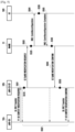
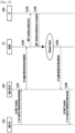
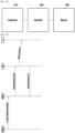
- FIG. 4 is a flowchart illustrating signaling for controlling the context of a UE between nodes according to an embodiment of the disclosure.
- FIG. 5 is a diagram illustrating the situation in which the update procedure of UE context fails in each node according to an embodiment of the disclosure.
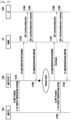
- FIGS. 6A and 6B are flowcharts for describing signaling when a DU consecutively triggers the update of UE context according to various embodiments of the disclosure.
- a first node (gNB-DU) 42a may transmit, to a second node (gNB-CU) 42b, a message to request a modification of the UE context (UE CONTEXT MODIFICATION REQUIRED) (S401).
- UE CONTEXT MODIFICATION REQUIRED UE CONTEXT MODIFICATION REQUIRED
- the UE CONTEXT MODIFICATION REQUIRED message to request a modification of the UE context may include the following information, for example.
- [Table 1] IE/Group Name Semantics Description gNB-CU UE F1AP ID UE delimiter used within a gNB-CU gNB-DU UE F1AP ID UE delimiter used within a gNB-DU Resource Coordinate Transfer Container It is a container for carrying an SgNB Resource Coordination Information IE, and includes an NR CGI, UL/DL, and Coordination Information.
- DU to CU RRC Information It is a container for carrying RRC layer information, such as Served Cell Information.
- DRB Required to be Modified List DRB ID Target DRB Delimiter to be modified DL UP TNL Information gNB-CU End Point Information of an F1 transport bearer for DL PDU transfer RLC Status RLC Status Information reconfigured in a gNB DU SRB Required to be Released List: SRB ID Target SRB Delimiter to be released DRB Required to be Released List: DRB ID Target DRB Delimiter to be released Cause UE Context Modification Required Message Transfer Cause
- the second node 42b that has received the message to request the modification of the UE context from the first node 42a may transmit a corresponding confirm message (F1 UE CONTEXT MODIFICATION CONFIRM) to the first node 42a (S402). Furthermore, the second node 42b may transmit, to a third node (MeNB) 41, a message (X2 SGNB MODIFICATION REQUIRED) to request a modification of the UE context through an X2 interface in response to the request for the modification of the UE context received from the first node 42a (S403).
- the third node 41 may perform a context update procedure for a UE 400 based on the UE context request message (X2 SGNB MODIFICATION REQUIRED) received from the second node 42b. For example, as illustrated in FIG. 4 , the third node 41 may transmit an RRC message (RRC ConnReconfiguration) for the update of the UE context to the UE 400 (S404).
- RRC ConnReconfiguration RRC ConnReconfiguration
- the UE 400 may perform an operation of updating the context of the UE 400 based on information included in the radio resource control (RRC) message received from the third node 41.
- RRC radio resource control
- the UE 400 may transmit, to the third node 41, an RRC message (RRC ConnReconfiguration Complete) including corresponding information (S405).
- the third node 41 that has received the RRC connection reconfiguration complete (RRC ConnReconfiguration Complete) message from the UE 400 may transmit, to the second node 42b, information included in the RRC connection reconfiguration complete (RRC ConnReconfiguration Complete) message received from the UE through the X2 interface (S406).
- the second node 42b that has received the message including information on the update of the UE context (X2 SGNB MODIFICATION CONFIRM) from the third node 41 may perform a procedure of changing the context of the UE based on the information (S407).
- results indicating whether the procedure of the UE context has been properly performed are not transmitted to the first node 42a.
- the second node 42b performs an operation of transmitting, to the first node 42a, the UE CONTEXT MODIFICATION COMFIRM message to notify that the UE CONTEXT MODIFICATION REQUIRED message has been successfully received regardless of whether the context update procedure of the UE 400 has been completed or has been properly performed.
- the UE CONTEXT MODIFICATION COMFIRM message may be transmitted from the second node 42b to the first node 42a in a sense of acknowledge (ACK) notifying that the message received from the first node 42a has been simply successfully received prior to the start of the update procedure of the context for the UE 400, while the update procedure of the context of the UE 400 is performed or after the update procedure of the context of the UE 400 is completed. That is, the UE CONTEXT MODIFICATION COMFIRM message may be transmitted through any one of arrows (S402-1, 2, and 3) indicated as dotted lines in FIG. 4 .
- arrows S402-1, 2, and 3
- the first node 42a cannot confirm whether the context of the UE has been successfully updated because the UE CONTEXT MODIFICATION CONFIRM message is transmitted from the second node 42b to the first node 42a regardless of whether the substantial update of the UE context has been completed.
- the update procedure of the UE context is performed through signaling between several nodes as described above. Accordingly, a problem may occur if an abnormal situation, such as a failure of transmission and reception in any one node or for any one signaling, occurs.
- a first node 52a may transmit a message (UE CONTEXT MODIFICATION REQUIRED) for the update of UE context to a second node 52b (S501).
- the second node 52b may transmit, to the first node 52a, a confirm message for the update of the UE context (UE CONTEXT MODIFICATION CONFIRM) in response thereto (S502).
- an error may occur in the second node 52b (S510) in the operation of initiating the update procedure of the UE context based on the message received from the first node 52a. Accordingly, an abnormal situation in which the update procedure of the UE context is not initiated may occur.
- the second node 52b may initiate the update procedure of the UE context based on the message received from the first node 52a, and may transmit, to a third node 51, a message (X2 SGNB MODIFICATION REQUIRED) to request the update of the UE context (S503).
- a message X2 SGNB MODIFICATION REQUIRED
- an abnormal situation may occur in which an RRC message to request the context update is not transmitted to a UE 500 due to a given error occurring in the third node 51 (S520) and the update procedure of the UE context ends in failure during the update procedure.
- the third node 51 may transmit, to the UE 500, an RRC message for the execution of a context update procedure based on the update request message for the UE context (X2 SGNB MODIFICATION REQUIRED) received from the second node 52b (S504).
- the reception and processing of the RRC message may fail or an abnormal situation may occur in which the execution of the update procedure of the UE context ends in failure because an error occurs due to a cause of wireless communication (S530).
- the UE 500 may perform a context update operation normally based on the RRC message received from the third node 51, and may transmit a corresponding complete message (RRC ConnReconfiguration Complete) to the third node 51 (S505).
- RRC ConnReconfiguration Complete a complete message
- an error may occur in which the reception of an RRC connection reconfiguration complete message fails (S540). Accordingly, an abnormal situation may occur in which the execution of the update procedure of the UE context ends in failure.
- the third node 51 receives, from the UE 500, a message (RRC ConnReconfiguration Complete) to notify that the update procedure of the UE context has been completed, it transmits, to the second node 52b, a message (X2 SGNB MODIFICATION CONFIRM) to notify the completion of the update of the UE context through an X2 interface (S506).
- a message (X2 SGNB MODIFICATION CONFIRM) to notify the completion of the update of the UE context through an X2 interface (S506).
- S550 an abnormal situation in which the update procedure of the UE context ends in failure due to a given error
- an NR base station is separated into the nodes of a CU and a DU in the state in which a UE has accessed an LTE base station and the NR base station through an EN-DC connection as described above, a problem occurs in the execution of a given operation if a resource allocation failure, a transmission or reception error, or an error in received information processing occurs because three or more nodes are involved in performing a given operation related to the UE.
- the update procedure of UE context may not be performed although processing in any one node or the transmission or reception of any one signaling between two nodes fails as described above. If a request for the update of UE context triggered by a first node is not properly performed, the first node has to trigger the request again. In this case, however, the first node does not receive, from a second node, any information indicating that the update of the UE context has failed. Accordingly, there is a problem in that the first node cannot perform any operation regarding that the first node has to transmit a corresponding re-request message again because a modification of requested UE context has failed or that the first node has to repeatedly transmit how many re-request messages.
- a request for the update of UE context may be triggered in plural times.
- the first node may trigger the transmission of a first context request message because a change in a parameter related to beam characteristic information received from a UE is necessary, and may then trigger the transmission of a second context request message because a change in a measurement parameter for the handover of the UE is necessary. If update requests for different parameter information are consecutively triggered as described above, a problem may occur because corresponding signaling is transmitted between several nodes.
- a first node 62a when a first node 62a determines that the update of UE context is necessary, it may transmit, to a second node 62b, a message (UE CONTEXT MODIFICATION REQUIRED-1st required) to request the update of the UE context (S601).
- the second node 62b may transmit a CONFIRM message (UE CONTEXT MODIFICATION CONFIRM) to a first node 61 (S602) in response to the UE CONTEXT MODIFICATION REQUIRED message received from the first node 62a, and may then initiate a context update procedure for a UE 600.
- UE CONTEXT MODIFICATION CONFIRM UE CONTEXT MODIFICATION CONFIRM
- the first node 62a transmits the UE context update request message to the second node 62b (S601), when a change in a parameter different from the context whose update has been requested is determined to be necessary, the first node 62a may transmit, to the second node 62b, a message (UE CONTEXT MODIFICATION REQUIRED-2nd required) to request a change in another parameter (S603).
- the second node 62b transmits a CONFIRM message (UE CONTEXT MODIFICATION CONFIRM) in response to the second context update request (S604), it may initiate a context update procedure for the UE 600.
- UE CONTEXT MODIFICATION CONFIRM UE CONTEXT MODIFICATION CONFIRM
- the second node 62b may transmit, to a third node 61, a message (X2 SGNB MODIFICATION REQUIRED) to request the update of the UE context (S605).
- the third node 61 may transmit an RRC message (RRC Reconfiguration) for the context update to the UE 600 (S606). If an operation for the context update is performed in the UE 600 and the update is completed, the UE 600 transmits, to the third node 61, an RRC message (RRC Reconfiguration Complete) including corresponding information (S607).
- the third node 61 that has received the RRC message may transmit, to the second node 62b, a message (X2 SGNB MODIFICATION CONFIRM) in order to notify the completion of the update of the UE context (S608).
- the second node 62b that has received, from the third node 61, information indicating that the update of the UE context has been completed may transmit, to the first node 62a, a message (UE CONTEXT MODIFICATION REQUEST) to request the update of the UE context, including an indicator indicating that has been completed (complete indicator), based on the information (S609).
- UE CONTEXT MODIFICATION REQUEST UE CONTEXT MODIFICATION REQUEST
- the complete indicator is an indicator to notify that parameter information related to the context of the UE has been updated, and does not include information regarding to which parameter the updated context of the UE is related. Furthermore, contents related to the update of the context of the UE are included in an RRC container and transmitted from the second node to the first node through the UE CONTEXT MODIFICATION REQUEST message, but the second node cannot confirm whether the update of the UE context has been completed because it performs only a function for transmitting information included in the RRC container to the UE without analyzing the information.
- a problem occurs in that when such a complete indicator is received after the first node makes twice context update requests, the first node is unaware that the complete indicator indicates update completion for which parameter information among the twice context requests. That is, the first node that has received the complete indicator is unaware of whether the update of context for which one of the first context update request and the second context update request has been completed. Accordingly, there is a problem in that the first node cannot determine whether to transmit a message to request the first context update again or whether to transmit a message to request the second context update again.
- the first node 62a may transmit a message (UE CONTEXT MODIFICATION REQUIRED-1st required) to request the update of the context to the second node 62b (S611).
- the second node 62b may transmit a confirm message (UE CONTEXT MODIFICATION CONFIRM) to the first node 62a (S612).
- the first node 62a may additionally transmit a UE context update request message (UE CONTEXT MODIFICATION REQUIRED-2nd required) to the second node 62b (S613).
- the second node 62b may transmit a confirm message (UE CONTEXT MODIFICATION CONFIRM) to the first node 62a (S614).
- the second node 62b that has received the request for the update of the UE context from the first node 62a may transmit, to the third node 61, a message to request the update of the UE context.
- the update request messages for the UE context (X2 SGNB MODIFICATION REQUIRED) transmitted from the second node 62b to the third node 61 may be transmitted to the third node 61 for each request triggered by the first node 62a (S615, S616).
- the third node 61 may transmit an RRC message (RRC Reconfiguration) to the UE 600 in accordance with the request for the update of the UE context received from the second node 62b.
- each RRC message may be transmitted in response to each UE context update request message (X2 SGNB MODIFICATION REQUIRED) received from the second node 62b (S617, S618).
- the UE 600 may perform the update operation of the UE context based on the RRC message received from the third node 61, and may transmit a corresponding complete message (RRC Reconfiguration complete) to the third node 61 (S619, S620).
- the third node 61 may transmit, to the second node 62b, a message (X2 SGNB MODIFICATION COFIRM) to notify the completion of the context update in response to each RRC reconfiguration complete message received from the UE 600 (S621, S622).
- the second node 62b may transmit, to the first node 62a, a message (UE CONTEXT MODIFICATION REQUEST), including an indicator for the completion of the update of the UE context (complete indicator), in response to the reception of the message (S623, S625).
- an update procedure according to the first-triggered UE context update request may be later than an update procedure according to the second-triggered UE context update request.
- the first node 62a receives, from the second node 62b, a first message to notify that the update of the UE context has been completed (S623), the first node cannot be aware that the corresponding message is related to the first request or the second request because a complete indicator included in the message does not notify an update for which parameter information.
- the first node 62a cannot be aware that which UE context has been updated even after it has transmitted, to the second node 62b, a response message (UE CONTEXT MODIFICATION RESPONSE) for the message (UE CONTEXT MODIFICATION REQUEST) received from the second node 62b (S624).
- UE CONTEXT MODIFICATION REQUEST a message to notify the completion of the update of the UE context is received from the second node (S625)
- the first node cannot be aware that such a message is related to the first request or the second request.
- the first node 62a transmits a message to request the update of the UE context several times, although information indicating that context update has been completed is received from the second node 62b in response to the message, there is a problem in that the first node cannot be aware that context corresponding to which one of the several request messages has been update.
- the disclosure proposes embodiments for efficiently performing signaling for control of UE context in the state in which an NR base station configured with a CU and a DU and an LTE base station have been connected to a UE through an EN-DC structure.
- an embodiment of the disclosure proposes a method of transmitting corresponding information to a DU if the update procedure of UE context is not performed normally.
- an embodiment of the disclosure proposes a method for a DU to confirm information on context whose update has been completed if the update of UE context has been completed based on a request for the update of the UE context.
- a UE CONTEXT MODIFICATION REFUSE message transmitted through an interface between a DU and a CU is defined so that the DU is notified of information on the failure of the update of UE context.
- the UE CONTEXT MODIFICATION REFUSE message is a message transmitted through the interface between the CU and the DU in order to notify the DU of an abnormal situation which may occur when the update procedure of the UE context is initiated after the CU receives a request message for the UE context from the DU.
- a UE CONTEXT MODIFICATION REFUSE message may be a message to notify a DU that the execution of a context update procedure has failed if the update procedure of UE context is determined to have failed for a given cause according to various examples described in FIG. 5 .
- Such a UE CONTEXT MODIFICATION REFUSE message may have included various types of information.
- the UE CONTEXT MODIFICATION REFUSE message may include information on a UE that has failed in a context update (e.g., the ID of the UE, that is, the ID of the UE for a CU and the ID of the UE for a DU) and an RRC container to be transmitted to a UE.
- the UE CONTEXT MODIFICATION REFUSE message may further include information on a time (wait time) when a DU that has received the UE CONTEXT MODIFICATION REFUSE message can request the update of UE context whose update has failed again and count (Retry Count) information, such as how many requests for the same context are possible.
- the UE CONTEXT MODIFICATION REFUSE message may include information on a failure cause of the update of UE context (information on a cause to refuse UE CONTEXT MODIFICATION REQUIRED).
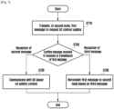
- FIG. 7 is a flowchart illustrating an operation of a DU for control of UE context according to an embodiment of the disclosure.
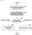
- FIG. 8 is a flowchart illustrating an operation of a CU for control of UE context according to an embodiment of the disclosure.
- a first node (DU) may detect the need for the update of some parameters according to communication while performing wireless communication with a UE. For example, the first node according to an embodiment of the disclosure may determine that a change in a parameter related to a measurement value for a cell configured in a UE is necessary or may determine that a change in a parameter related to beam characteristic information for each cell is necessary based on the results of wireless communication with the UE.
- the first node may report, to a second node (CU) including an RRC layer, at least one parameter for which a change has been determined to be necessary. That is, the first node may transmit a first message to request the update of UE context related to the parameter for which a change has been determined to be necessary (S710).
- CU second node
- RRC layer RRC layer
- the first message may be a UE CONTEXT MODIFICATION REQUIRED message transmitted through a fronthaul interface connected between the first node and the second node.
- the corresponding message may include the pieces of information in Table 1.
- the first node may confirm which message is received from the second node in response to the transmission of the first message (S720).
- the first node may receive, from the second node, a second message to indicate the completion of the update of the UE context in response to the transmission of the first message.
- the second message to indicate the completion of the update of the UE context may be a UE CONTEXT MODIFICATION REQUEST message transmitted through the fronthaul interface, for example.
- a second message according to an embodiment of the disclosure may include information (e.g., a complete indicator) to indicate update completion for requested UE context as described above with reference to FIGS. 6A and 6B . That is, the second message according to an embodiment of the disclosure may include information on a UE or information, such as which UE context has been updated if a plurality of UE context update requests has been made for a plurality of UEs.
- information e.g., a complete indicator
- the first node may perform wireless communication with the UE based on UE context whose update has been completed (S730).
- the first node may receive, from the second node, a third message to indicate the failure of the update of the UE context in response to the transmission of the first message.
- the third message to indicate the failure of the update of the UE context may be a UE CONTEXT MODIFICATION REFUSE message transmitted through a fronthaul interface, for example.
- a third message may include information on a corresponding procedure failed due to what cause by which node during a procedure of updating UE context, which is performed between a UE and a second node and the third node.
- the third message may include information, such as that the third node has failed in a corresponding procedure after a request message for the update of UE context for initiating the update procedure of the UE context is transmitted from the second node to the third node or that a UE that has received the indication of the update procedure of UE context from the third node has failed in the corresponding procedure while performing the update of the corresponding context.
- the third message may include the pieces of information in Table 2 as described above. That is, the third message may include the ID of a UE for a first node and a second node or information, such as when and how many times a first message for requesting the update of corresponding UE context can be transmitted.
- the first node may transmit, to the second node, the first message for requesting the update of the UE context based on information included in the third message again (S740).
- a second node may receive, from a first node (DU), a first message to request the update of UE context (S810).
- the second node may initiate the update procedure of the UE context.
- the second node may transmit, to a third node, a message to request the execution of the update operation of the UE context between the third node and a UE (S820).
- the third node may perform the update operation of the UE context between the third node and the UE.
- the third node may indicate the update operation of the UE context for the UE using an RRC message.
- the UE may perform the update operation of the UE context based on the indication.
- the UE may transmit, to the third node, an RRC message including corresponding result information as a response.
- the third node may transmit, to the second node, result information for the update operation of the UE context between the third node and the UE. For example, if the update operation of the UE context fails in the third node or the UE due to a given cause, the third node may transmit, to the second node, a message (REFUSE message) including corresponding information through an X2 interface. Furthermore, when the update operation of the UE context is successfully completed, the third node may transmit, to the second node, a message (CONFIRM message) including corresponding information through the X2 interface.
- a message REFUSE message
- CONFIRM message a message including corresponding information through the X2 interface.
- the second node After initiating the update procedure of the UE context, the second node according to an embodiment of the disclosure may confirm the results of the update procedure of the UE context based on a message received from the third node (S830).
- the second node may transmit, to the first node, a second message to request the update of the corresponding UE context (S840).
- the second message may be a UE CONTEXT MODIFICATION REQUEST message transmitted through a fronthaul interface between the first node and the second node.
- the second node may transmit, to the first node, a third message to notify the failure of the update of the corresponding UE context (S850).
- the third message may be a UE CONTEXT MODIFICATION REFUSE message transmitted through the fronthaul interface, including information received from the third node or corresponding information if the update of the corresponding UE context fails in the second node due to a given cause.
- a DU can rapidly determine whether to request the update procedure of the corresponding UE context to be initiated again based on information included in a message received from a CU or whether the DU has to perform wireless communication with a UE based on updated context.
- a CU transmits information, such as that the update of which UE context has been completed, and provides a DU with a failure cause if the update of UE context has failed and information related to an operation for recovering the failure. Accordingly, there is an effect in that the update procedure of UE context can be more efficiently performed without delay.
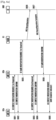
- FIGS. 9 to 13 are flowcharts for describing examples in which a CU transmits, to a DU, a REFUSE message according to embodiments of the disclosure in various cases where the update procedure of UE context fails according to various embodiments of the disclosure.
- a first node 92a may transmit, to a second node 92b, a message (UE CONTEXT MODIFICATION REQUIRED) to request the update of the UE context (S901).
- the second node 92b may initiate the update procedure of the UE context based on the received message.
- FIG. 9 further illustrates a third node 91 and UE 900.
- an abnormal situation may occur in the operation for the second node 92b to initiate the update procedure of the UE context.
- the update procedure of the UE context may not be initiated due to a problem, such as that the second node 92b fails in the reception of a UE CONTEXT MODIFICATION REQUIRED message from the first node 92a.
- the second node 92b may transmit, to the first node 92a, a UE CONTEXT MODIFICATION REFUSE message in order to notify the first node 92a that the update procedure of the UE context has not been initiated (S902).
- the UE CONTEXT MODIFICATION REFUSE message may include information on a UE context procedure failure attributable to a reception failure in the second node 92b.
- the first node 92a that has received the REFUSE message as described above can rapidly confirm that the procedure requested from the second node 92b has failed. Accordingly, the first node may subsequently transmit an update request for the same context to the second node 92b again.
- a first node 102a may transmit, to a second node 102b, a message (UE CONTEXT MODIFICATION REQUIRED) to request the update of the UE context (S1001).
- the second node 102b may initiate the update procedure of the UE context based on the received message. That is, the second node 102b may transmit, to a third node 101, a message (X2 UE CONTEXT MODIFICATION REQUIRED) to request the update of the UE context based on the request message received from the first node 102a (S 1002).
- the third node 101 needs to transmit, to a UE 1000, an RRC message for the execution of the context update in response to the UE context update request received from the second node 102b, but an abnormal situation may occur prior to the execution of a corresponding operation as illustrated in FIG. 10 .
- a problem such as that the third node 101 fails in the reception of the X2 SGNB MODIFICATION REQUIRED message or does not transmit a corresponding RRC message to the UE 1000, may occur.
- the third node 101 may transmit, to the second node 102b, a message (X2 SGNB MODIFICATION REFUSE) to notify that the update procedure of the UE context has failed through an X2 interface (S1003).
- a message X2 SGNB MODIFICATION REFUSE
- the second node 102b that has received the message, including information on the failure of the update of the UE context, from the third node 101 may transmit, to the first node 102a, a REFUSE message according to an embodiment of the disclosure (S1004).
- the first node 102a may determine whether to transmit a message to request the update of the corresponding context again based on the reception of the REFUSE message from the second node 102b. For example, after a given time (wait time) expires, the first node 102a may transmit, to the second node 102b, a message to request the update of the context based on the REFUSE message.
- a first node 112a may transmit, to a second node 112b, a message (UE CONTEXT MODIFICATION REQUIRED) to request the update of the UE context (S1101).
- the second node 112b may transmit, to a third node 111, a message (X2 SGNB MODIFICATION REQUIRED) to request the update of the UE context based on the received message (S1102).
- the third node 111 may transmit, to a UE 1100, an RRC message for the execution of the context update in response to the UE context update request received from the second node 112b (S1103).
- the UE 1100 may initiate an operation for updating the context based on the RRC message received from the third node 111. In this case, the reception of the RRC message may fail or the context update procedure may fail due to a cause, such as a wireless communication situation.
- the UE 1100 transmits, to the third node 111, an RRC message (RRC ConnReconfiguration request) for the connection reconfiguration of the third node 111 (S1104).
- the UE 1100 reconfigures an RRC connection with the third node 111 based on a message (RRC ConnReestablishment) received from the third node 111 (S1105).
- the UE 1100 may transmit, to the third node 111, a message (RRC ConnReestablishment Complete) to notify RRC connection reconfiguration completion (S1106).
- the UE 1100 has reconfigured the RRC connection with the third node 111 as described above, but has not performed the update operation of the UE context triggered by the first node 112a. Accordingly, after the third node 111 receives the reconfiguration complete message for the RRC connection, it may transmit, to the second node 112b, a message (X2 SGNB MODIFICATION REFUSE) to notify that the update of the UE context has failed (S1107).
- a message X2 SGNB MODIFICATION REFUSE
- the second node 112b may transmit, to the first node 112a, a message (UE CONTEXT MODIFICATION REFUSE) to notify the failure of the update of the UE context (S1108).
- UE CONTEXT MODIFICATION REFUSE UE CONTEXT MODIFICATION REFUSE
- the first node 112a determines whether to request the context update again based on the REFUSE message. For example, the first node 112a may determine whether to perform the transmission of the message to request the update of the corresponding context again based on a comparison between an update failure count for the corresponding context and retry count information included in the REFUSE message.
- a first node 122a may transmit, to a second node 122b, a message (UE CONTEXT MODIFICATION REQUIRED) to request the update of the UE context (S1201).
- the second node 122b may transmit, to a third node 121, a message (X2 SGNB MODIFICATION REQUIRED) to request the update of the UE context (S1202).
- the third node 121 may transmit, to a UE 1200, an RRC message for the execution of the context update in response to the UE context update request received from the second node 122b (S1203).
- the UE 1200 may initiate an operation for updating the context based on the RRC message received from the third node 121. Furthermore, when the context update operation is completed, the UE 1200 may transmit, to the third node 121, an RRC message (RRC ConnReconfiguration Complete) including corresponding information (S1204).
- RRC ConnReconfiguration Complete an RRC message including corresponding information (S1204).
- An abnormal situation may occur while the third node 121 performs an operation for notifying the second node 122b of the completion of the update of the UE context based on the RRC message received from the UE 1200.
- the third node 121 may transmit, to the second node 122b, an REFUSE message (X2 SGNB MODIFICATION REFUSE) including information indicating that the update of the UE context has failed (S1205).
- the second node 122a that has received X2 SGNB MODIFICATION REFUSE from the third node 121 as described above may transmit, to the first node 122a, a message (UE CONTEXT MODIFICATION REFUSE) to notify that the update of the UE context has failed (S1206).
- the first node 122a may determine whether to retransmit a message to request the update of the UE context based on the received message.
- a first node 132a may transmit, to a second node 132b, a message (UE CONTEXT MODIFICATION REQUIRED) to request the update of the UE context (S1301).
- the second node 132b may transmit, to a third node 131, a message (X2 SGNBMODIFICATION REQUIRED) to request the update of the UE context based on the received message (S1302).
- the third node 131 may transmit, to a UE 1300, an RRC message for the execution of the context update in response to the UE context update request received from the second node 132b (S1303).
- the UE 1300 may initiate an operation for updating the context based on the RRC message received from the third node 131.
- the UE 1300 may transmit, to the third node 131, an RRC message (RRC ConnReconfiguration Complete) including corresponding information (S1304).
- the third node 131 may transmit, to the second node 132b, a message (X2 SGNB MODIFICATION CONFIRM) for notifying the completion of the update of the UE context based on the RRC message received from the UE 1300 (S1305).
- a situation such as the failure of the execution of the update procedure of the UE context or the impossible execution of the update procedure attributable to a given cause although the second node 132b has received the message, may occur.
- the second node 132b may transmit, to the first node 132a, a message (UE CONTEXT MODIFICATION REFUSE) to notify the failure of the update procedure of the UE context (S1306). Furthermore, the second node 132b may transmit, to the third node 131, a message (X2 SGNB MODIFICATION REQUIRED) including a roll back indicator to indicate the cancellation of a corresponding context update procedure due to the failure of the corresponding context update (S1307).
- a message UE CONTEXT MODIFICATION REFUSE
- X2 SGNB MODIFICATION REQUIRED a message including a roll back indicator to indicate the cancellation of a corresponding context update procedure due to the failure of the corresponding context update
- the third node 131 may transmit, to the UE 1300, an RRC message including information for rolling the updated corresponding context back based on the X2 SGNB MODIFICATION REQUIRED message (S1308). After performing an operation for rolling the UE context back, the UE 1300 may transmit, to the third node, a message (RRCConnReconfiguration Complete) to notify the corresponding completion (S1309).
- the third node 131 may transmit, to the second node 132b, a message (X2 SGNB MODIFICATION CONFIRM) including corresponding information (S1310).
- the REFUSE message may be used for various causes.
- a CU may refuse a corresponding request using the UE CONTEXT MODIFICATION REFUSE message.
- a CU may refuse the corresponding request using a UE CONTEXT MODIFICATION REFUSE message based on a session for the UE CONTEXT MODIFICATION REQUEST that is previously in progress.
- a second node may notify that the update of UE context cannot be now performed using a UE CONTEXT MODIFICATION REFUSE message in a given situation although the update of the UE context does not fail.
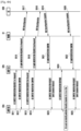
- FIGS. 14 and 15 are diagrams illustrating examples in which a CU transmits, to a DU, a REFUSE message according to embodiments of the disclosure in a given situation according to various embodiments of the disclosure.
- a first node 142a when the update of UE context is determined to be necessary, may transmit, to a second node 142b, a message (UE CONTEXT MODIFICATION REQUIRED - 1st required) to request the update of the UE context (S1401).
- the second node 142b may transmit, to the first node 142a, a message (UE CONTEXT MODIFICATION CONFIRM) for confirming the reception of the message (S1402).
- the second node 142b may transmit, to a third node 141, a message (SGNB CONTEXT MODIFICATION REQUIRED - 1st required) for the update of the UE context in response to the request (S1403).
- a message (SGNB CONTEXT MODIFICATION REQUIRED - 1st required) for the update of the UE context in response to the request (S1403).
- the first node 142a may additionally transmit, to the second node 142b, a request for another UE context (UE CONTEXT MODIFICATION REQUIRED - 2nd required) (S1404).
- the second node 142b may transmit a REUSE message (UE CONTEXT MODIFICATION REFUSE) to the first node 142a (S1405).
- the second node 142b uses the REFUSE message in a given situation in which the update procedure of UE context cannot be initiated. Accordingly, there is an effect in that an ambiguous situation in which the first node cannot be aware of whether the update procedure of UE context is in progress can be solved.
- pieces of signaling for the context update are transmitted and received between the third node 141 and a UE 1400 (S1406, S1407).
- the third node 141 may transmit, to the second node 142b, a message (SGNB MODIFICATION CONFIRM) including result information according to the signaling (S1408).
- the second node 142b may transmit, to the first node 142a, a message (UE CONTEXT MODIFICATION REQUEST) including information (complete indicator) indicating that the update of the UE context has been completed based on the message (S1409).
- the second node may determine that handover is necessary.
- the existing second node is named a second source node
- a second node that is a target of handover is named a second target node.
- a second source node 152b transmits. to a third node 151, signaling (SGNB CHANGE REQUIRED) for a handover procedure trigger (S1501).
- the third node 151 that has received the signaling may trigger a new call setup procedure by transmitting an SGNB Addition Request message to a second target node 152b' (S1502).
- the second target node 152b' may transmit an SGNB Addition Request Ack message to the third node 151 according to an embodiment of the disclosure (S1503).
- the third node 151 may transmit signaling for an RRC reconfiguration to a UE 1500 (S1504).
- the UE 1500 may transmit an RRC complete message to the third node 151 (S1505), so an RRC reconfiguration procedure may be performed.
- the third node 151 according to an embodiment of the disclosure transmits an SGNB CHANGE CONFIRM message to a second source node 152b in response to the completion of the RRC reconfiguration procedure (S1506), and transmits an SGNB RECONFIGURATION COMPLETE message to the second target node 152b' (S1507).
- the second source node 152b after receiving the SGNB CHANGE CONFIRM message, the second source node 152b requests an operation necessary because a belonging SgNB of the UE managed by the first source node is changed by transmitting, to the first node 152a, a UE CONTEXT MODIFICATION REQUEST message including a Complete Indicator (S1510).
- the corresponding necessary operation includes Data Forwarding to the target node and corresponding source-side UE context release. Accordingly, the SgNB Change procedure for the corresponding UE can be completed.
- the first node 152a transmits a message (UE CONTEXT MODIFICATION REQUIRED) to request the update of UE context in the state in which the first node is unaware of a handover situation between the second source node 152b and the second target node 152b' (S1508).
- the second source node 152b determines that the update of the UE context is impossible in the state in which handover is in progress, and transmits, to the first node 152a, an F1 UE CONTEXT MODIFICATION REFUSE message according to an embodiment of the disclosure (S1509). Accordingly, the first node 152a can confirm that the update of the UE context cannot be performed.
- a CU may transmit a message to notify that the progress of the context procedure of a UE has been suspended.
- a CU may transmit, to a DU, a UE CONTEXT MODIFICATION SUSPEND message for transmitting corresponding information.
- the DU can be aware that the update of the corresponding context has been suspended until a UE CONTEXT MODIFICATION RESUME message to notify the progress (or resumption) of the context update procedure of the UE is received from the CU.
- a DU may not perform a separate re-request although a message to notify that the update of corresponding context has been successfully completed is not received for a given time.
- FIG. 16 is a diagram illustrating an example in which a base station whose CU and DU have been separated performs the context update of a UE according to an embodiment of the disclosure.
- an NR base station (gNB) 162 may initiate a serving beam based on a physical random access channel (PRACH) transmitted by a UE 1600 that has performed initial access to the NR base station 162, and may transmit, to the UE 1600, an RRC reconfiguration message including configuration information related to an RRC connection with the UE 1600 (S1601). Furthermore, the NR base station (gNB) 162 may receive, from the UE 1600, CSI reporting information based on the RRC reconfiguration message (S1602). In this case, the CSI reporting information may include a synchronization signal block rank indicator (SSBRI), reference signal received power (RSRP), etc.
- SSBRI synchronization signal block rank indicator
- RSRP reference signal received power
- the NR base station 162 may determine that a modification of beam-related UE context is necessary based on the CSI reporting information received from the UE 1600. For example, the NR base station 162 according to an embodiment of the disclosure may determine that a modification of UE context information related to parameters that are included in Table 3 and that are related to beam control of a MAC layer.
- RRC IEs Description nzp_CSI_RS_Resource qcl_InfoPeriodicCSI_RS
- For a target periodic CSI-RS contains a reference to one TCI-State in TCI-States for providing the QCL source and QCL type.
- the source can be SSB or another periodic-CSI-RS.
- TCI-State which has this value for tci-StateId and is defined in tci-StatesToAddModList in the PDSCH-Config included in the BWP-Downlink corresponding to the serving cell and to the DL BWP to which the resource belongs to.
- csi_ResourceConfig csi_RS_ResourceConfigId Used in CSI-ReportConfig to refer to an instance of CSI-ResourceConfig csi_SSB_ResourceSetList Contains up to maxNrofNZP-CSI-RS-ResourceSetsPerConfig resource sets if ResourceConfigType is 'aperiodic' and 1 otherwise.
- L1 parameter 'ResourceSetConfigList' (see 38.214, section 5.2.1.3.1) bwp_Id The DL BWP which the CSI-RS associated with this CSI-ResourceConfig are located in.
- L1 parameter 'BWP-Info' (see 38.214, section 5.2.1.2 resourceType Time domain behavior of resource configuration.
- L1 parameter 'ResourceConfigType' (see 38.214, section 5.2.2.3.5). It does not apply to resources provided in the csi-SSB-ResourceSetList.
- the SRS-Config IE is used to configure sounding reference signal transmissions.
- the configuration defines a list of SRS-Resources and a list of SRS-ResourceSets. Each resource set defines a set of SRS-Resources.
- the network triggers the transmission of the set of SRS-Resources using a configured aperiodicSRS-ResourceTrigger (L1 DCI).
- tci_StatesPDCCH_ToAddLi st A subset of the TCI states defined in pdsch-Config.
- TCI-State RS Set
- PDCCH Physical Downlink Control Channel
- pdsch_tciStatesToAddMod List A list of Transmission Configuration Indicator (TCI) states indicating a transmission configuration which includes QCL-relationships between the DL RSs in one RS set and the PDSCH DMRS ports (see 38.214, section 5.1.4).
- TCI Transmission Configuration Indicator
- Reference RS can be SSB/CSI-RS/SRS. If the list has more than one element, MAC-CE selects a single element (see TS 38.321, section FFS_Section and TS 38.213, section 9.2.2).
- radioLinkMonitoringConfig The RadioLinkMonitoringConfi g IE is used to configure radio link monitoring for detection of beam- and/or cell radio link failure.
- CSI-ReportConfig for BM
- the IE CSI-ReportConfig is used to configure a periodic or semi-persistent report sent on PUCCH on the cell in which the CSI-ReportConfig is included, or to configure a semi-persistent or aperiodic report sent on PUSCH triggered by DCI received on the cell in which the CSI-ReportConfig is included (in this case, the cell on which the report is sent is determined by the received DCI).
- the DU of the NR base station 162 may transmit, to the CU of the NR base station 162, a UE CONTEXT MODIFICATION REQUEST message including UE context information for a given parameter that belongs to the parameters of RRC IEs included in Table 3 and for which updates are necessary through communication with the UE 1600.
- the DU of the NR base station 162 may transmit a corresponding request message to the CU of the NR base station 162. Furthermore, after the request message is transmitted, if the update of the UE context related to CSI _ReportConfig for BM is determined to be necessary, the DU of the NR base station 162 may transmit, to the CU of the NR base station 162, a message to request the update of the corresponding UE context independently of the request message.
- the CU of the NR base station 162 that has received the UE context update request from the DU of the NR base station 162 as described above may perform a UE context update procedure according to an embodiment of the disclosure. Furthermore, the CU of the NR base station 162 may transmit, to the DU of the NR base station 162, result information indicating whether a serving beam for the UE 1600 has been changed (s1603).
- the NR base station 162 may perform wireless communication with the UE according to the updated serving beam based on the SSBRI feedback of the UE 1600.
- the NR base station 162 may transmit an RRC reconfiguration message (S 1604) or transmit an MAC-control element (CE) (S1605) to the UE 1600 based on the updated serving beam.
- RRC reconfiguration message S 1604
- CE MAC-control element
- FIG. 17 is a diagram illustrating the configuration of a base station according to an embodiment of the disclosure.
- FIG. 18 is a diagram illustrating the configuration of a UE according to an embodiment of the disclosure.
- the base station may include the DU of an NR base station, the CU of the NR base station and an LTE base station.
- the base station may include a transceiver 1710, a controller 1720 (e.g., at least one processor), and a memory 1730.
- the controller 1720 of the base station may be defined as a circuit or an application-specific integration circuit or at least one processor.
- the transceiver 1710 of the base station may transmit and receive signals to and from another network entity.
- the transceiver 1710 may perform wireless communication with an external device, such as a UE, through a wireless interface, or may perform communication with another base station or network function entity using a given interface unit 1711.
- the interface unit 1711 of the transceiver 1710 of the CU of the NR base station may include a fronthaul interface unit for communicating with the DU of the NR base station, and may include an X2 interface unit for communicating with the LTE base station.
- the interface unit 1711 of the transceiver 1710 of the DU of the NR base station may include a fronthaul interface unit for communicating with the CU of the NR base station.
- the interface unit 1711 of the transceiver 1710 of the LTE base station may include an X2 interface unit for communicating with the CU of the NR base station.
- the controller 1720 of the base station may control an overall operation of the base station according to an embodiment proposed in the disclosure.
- the controller 1720 may control the transceiver 1710 and the memory 1730 to perform the operations according to the embodiments described in the drawings.
- the controller 1720 of the DU of the NR base station may detect whether the update of UE context is necessary through communication with a UE, and may control the transceiver 1710 to transmit, to the CU of the NR base station, a message to request the corresponding context update.
- the controller 1720 of the CU of the NR base station may initiate a UE context update procedure in response to a request message received from the DU of the NR base station, and may control the transceiver 1710 to transmit, to the DU of the NR base station, a message including corresponding information.
- the controller 1720 of the LTE base station may perform a context update procedure along with a UE based on a UE context update request received from the NR base station, and may control the transceiver 1710 to transmit corresponding results to the NR base station.
- the memory 1730 of the base station may store at least one of information transmitted and received through the transceiver 1710 and information generated through the controller 1720.
- the memory 1730 of the NR base station may store a function separation method of a fronthaul interface configured between the CU and the DU and parameters for each layer.
- the UE may include a transceiver 1810, a controller 1820 (e.g., at least one processor), and a memory 1830.
- the controller 1820 of the UE may be defined as a circuit or an application-specific integration circuit or at least one processor.
- the transceiver 1810 of the UE may transmit and receive signals to and from another network entity.
- the transceiver 1810 may transmit and receive radio signals to and from an external device or a base station through a radio interface.
- the controller 1820 of the UE may control an overall operation of the UE according to an embodiment proposed in the disclosure.
- the controller 1820 may control to perform a UE context update operation based on an RRC message received from a base station.
- the memory 1830 of the UE may store information transmitted and received through the transceiver 1810 and information generated through the controller 1820.
- a method of notifying the failure of an F1 UE CONTEXT MODIFICATION REQUIRED/CONFIRM procedure by transmitting an F1 UE CONTEXT CONFIRM message without using an F1 UE CONTEXT MODIFICATION REFUSE message may be used.
- FIG. 19 is a diagram for describing an embodiment in which a UE CONTEXT MODIFICATION REFUSE message is not used according to an embodiment of the disclosure.
- a DU after transmitting a UE CONTEXT MODIFICATION REQUIRED to a CU, a DU according to an embodiment of the disclosure drives a timer for the transmission of the message.
- the CU After receiving the corresponding message, the CU transmits X2 SGNB MODIFICATION REQUIRED to an eNB and then drives a timer. If an RRC Reconfiguration procedure fails due to a given cause (e.g., a UE-side process failure), the eNB transmits X2 SGNB MODIFICATION REFUSE to the CU after the timer expires.
- a given cause e.g., a UE-side process failure
- the CU that has received the X2 SGNB MODIFICATION REFUSE may notify a UE context modification procedure failure without transmitting any message instead of using F1 UE CONTEXT MODIFICATION REFUSE. If any response is not received, the DU may consider the F1 UE CONTEXT MODIFICATION REQUIRED procedure to have failed after the timer expires because the timer is driving (however, the corresponding scheme requires a prerequisite that the CU can transmit an F1 UE CONTEXT MODIFICATION CONFIRM message to the DU only if the CU has to regularly receive an X2 SGNB MODIFICATION CONFIRM message from the eNB).
- a method of notifying the failure of an F1 UE CONTEXT MODIFICATION REQUIRED/CONFIRM procedure by including a refuse indication IE while transmitting an F1 UE CONTEXT MODIFICATION CONFIRM message without an F1 UE CONTEXT MODIFICATION REFUSE message may be used.
- FIG. 20 is a flowchart for describing a method of notifying a failure of a UE CONTEXT procedure using an F1 UE CONTEXT MODIFICATION CONFIRM message according to an embodiment of the disclosure.
- a DU drives a timer for the transmission of the message.
- the CU transmits X2 SGNB MODIFICATION REQUIRED to an eNB and then drives a timer. If an RRC Reconfiguration procedure fails due to a given cause (e.g., a UE-side process failure), the eNB transmits X2 SGNB MODIFICATION REFUSE to the CU after the timer expires.
- the CU that has received X2 SGNB MODIFICATION REFUSE may notify a UE context modification procedure failure by transmitting an F1 UE CONTEXT MODIFICATION CONFIRM message including a Refuse Indication IE instead of using F1 UE CONTEXT MODIFICATION REFUSE.
- the following table illustrates an F1 UE CONTEXT MODIFICATION CONFIRM message format to which a corresponding Refuse Indication IE has been added.
- a method of not including an RRC container IE in F1 UE CONTEXT MODIFICATION CONFIRM may be taken into consideration.
- FIG. 21 is a diagram for describing a method of notifying a failure of a UE context update procedure, indicating that an RRC container IE is not included in an F1 UE CONTEXT MODIFICATION CONFIRM message according to an embodiment of the disclosure.
- a method of notifying the failure of an F1 UE CONTEXT MODIFICATION REQUIRED/CONFIRM procedure by not intentionally including a mandatory RRC container IE while transmitting an F1 UE CONTEXT MODIFICATION CONFIRM message without using an F1 UE CONTEXT MODIFICATION REFUSE message may be used.
- FIGS. 22 and 23 are diagrams for describing methods for a change after CONFIRM for a UE CONTEXT MODIFICATION REQUIRED request from a first node to a second node according to various embodiments of the disclosure.
- the first node according to an embodiment of the disclosure may be understood as the DU (gNB-DU) of an NR base station
- the second node may be understood as the CU (gNB-CU) of the NR base station
- a third node may be understood as an LTE base station.
- the first node 222a, 232a may transmit, to the second node 222b, 232b, a message (UE CONTEXT MODIFICATION REQUIRED) to request the UE context update (S2201, S2301).
- the second node 222b, 232b may transmit, to the first node 222a, 232a, a message (UE CONTEXT MODIFICATION CONFIRM) for confirming the reception of the message (S2202, S2302).
- the second node 222b, 232b may transmit, to the third node 221, 231, a message (SGNB CONTEXT MODIFICATION REQUIRED) for the UE context update (S2203, S2303).
- SGNB CONTEXT MODIFICATION REQUIRED a message for the UE context update (S2203, S2303).
- the second node 222b, 232b may transmit a UE Context Modification Request message, including a Complete Indicator having a value of 'FALSE', when it transmits the UE Context Modification Request message to the first node 222a, 232a (S2204, S2304).
- the first node 222a, 232a may retransmit a UE Context Modification Required message to the second node 222b, 232b.
- the confirm message including the complete indicator may be understood as 'Meaningful Confirm' as illustrated in the drawings.
- a node that has first requested a UE context update is notified of result information for a UE context update procedure. Accordingly, there is an effect in that a node can perform an operation suitable for each situation of the success or failure of a corresponding procedure without unnecessary resource consumption.
Landscapes
- Engineering & Computer Science (AREA)
- Computer Networks & Wireless Communication (AREA)
- Signal Processing (AREA)
- Databases & Information Systems (AREA)
- Mobile Radio Communication Systems (AREA)
Claims (15)
- Verfahren, durchgeführt von einer verteilten Einheit, DU (42a), eines Knotens B der nächsten Generation, gNB, in einem drahtlosen Kommunikationssystem, wobei der gNB mit einem Benutzergerät, UE, gemäß dualer Konnektivität, DC, mit einem weiterentwickelten Knoten B, eNB (41, 61, 111, 141, 151) verbunden ist, wobei das Verfahren umfasst:Übertragen (S1508), an eine zentrale Einheit, CU (42b), des gNB, einer Nachricht über eine erforderliche UE-Kontextänderung zum Anfordern einer Aktualisierung eines UE-Kontextes, wobei die Nachricht über eine erforderliche UE-Kontextänderung Folgendes enthält:eine gNB-CU UE-Kennung, ID, zum Identifizieren des UE innerhalb der CU, undeine gNB-DU UE-ID zum Identifizieren des UE innerhalb der DU;Empfangen (S1509), von der CU (42b), einer UE-Kontextänderungsverweigerungsnachricht, die anzeigt, dass die UE-Kontextänderung nicht erfolgreich ist, wobei die UE-Kontextänderungsverweigerungsnachricht Folgendes enthält:die gNB-CU UE-ID,die gNB-DU UE-ID undInformationen über eine Ursache für die erfolglose UE-Kontextänderung undEmpfangen (S1510), von der CU (42b), einer UE-Kontextänderungsanforderungsnachricht , die einen vollständigen Indikator enthält, um anzuzeigen, dass eine sekundäre gNB-(SgNB)-Wechselprozedur zwischen dem eNB (41, 61, 111, 141, 151) und dem gNB abgeschlossen wurde, um die Datenweiterleitung an einen Zielknoten und die Freigabe des UE-Kontexts zu bewirken.
- Verfahren nach Anspruch 1,wobei die DU (42a) des gNB und die CU (42b) des gNB über eine F1-Schnittstelle verbunden sind,wobei die CU (42b) des gNB und des eNB (41, 61, 111, 141, 151) über eine X2-Schnittstelle verbunden sind,wobei die CU eine Funkressourcensteuerungs-, RRC,-Schicht und eine Paketdatenkonvergenzprotokoll-, PDCP,-Schicht aufweist, undwobei die DU eine Funkverbindungssteuerungs-, RLC,-Schicht, eine Mediumzugriffssteuerungs-, MAC,-Schicht, und eine physikalische, PHY, Schicht aufweist.
- Verfahren nach Anspruch 2,
wobei die Nachricht über eine erforderliche UE-Kontextänderung Identifikationsinformationen über einen oder mehrere zu ändernde Datenfunkträger, DRBs, und Downlink-, DL,-Benutzerebenen-, UP,-Tunnel-, TNL,-Informationen enthält. - Verfahren nach Anspruch 1,wobei die Nachricht über eine erforderliche UE-Kontextänderung einen Ressourcen-Koordinations-Transfer-Container enthält,wobei der Ressourcen-Koordinations-Transfer-Container ein SgNB-Ressourcen-Koordinations-Informationselement, IE, für den eNB enthält, undwobei das SgNB-Ressourcenkoordinations-IE Informationen über eine globale Neufunk-, NR,-Zellenkennung, CGI, und Koordinationsinformationen enthält.
- Verfahren, durchgeführt von einer zentralen Einheit, CU (42b), einer Basisstation eines Knotens der nächsten Generation, gNB, in einem drahtlosen Kommunikationssystem, wobei der gNB mit einem Benutzergerät, UE, gemäß dualer Konnektivität, DC, mit einem weiterentwickelten Knoten B, eNB (41, 61, 111, 141, 151) verbunden ist, wobei das Verfahren umfasst:Übertragen (S1501) einer SGNB CHANGE REQUIRED-Nachricht an den eNB (41, 61, 111, 141, 151) zum Auslösen einer Handover-Prozedur für das UE;Empfangen (S1508), von einer verteilten Einheit, DU (42a), des gNB, einer Nachricht über eine erforderliche UE-Kontextänderung, um eine Aktualisierung eines UE-Kontextes anzufordern, wobei die Nachricht über eine erforderliche UE-Kontextänderung Folgendes enthält:eine gNB-CU UE-Kennung, ID, zum Identifizieren des UE innerhalb der CU, undeine gNB-DU UE-ID zum Identifizieren des UE innerhalb der DU;basierend auf dem Bestimmen, dass die Aktualisierung des UE-Kontextes aufgrund der laufenden Handover-Prozedur für das UE unmöglich ist, Übertragen (S1509) einer UE-Kontextänderungsverweigerungsnachricht, die einen Fehler der UE-Kontextaktualisierung meldet, an die DU (42a), wobei die UE-Kontextänderungsverweigerungsnachricht Folgendes enthält:die gNB-CU UE-ID,die gNB-DU UE-ID undInformationen über eine Fehlerursache für die Aktualisierung des UE-Kontextes, undEmpfangen (S1506) einer SGNB-CHANGE CONFIRM-Nachricht vom eNB (41, 61, 111, 141, 151) als Reaktion auf die SGNB-CHANGE REQUIRED-Nachricht und Übertragen (S1510), an die DU (42a), einer UE-Kontextänderungsanforderungsnachricht, die einen vollständigen Indikator enthält, um anzuzeigen, dass eine SgNB-Änderungsprozedur zwischen dem eNB (41, 61, 111, 141, 151) und dem gNB abgeschlossen wurde, um eine Datenweiterleitung an einen Zielknoten der Handover-Prozedur und eine Freigabe des UE-Kontextes zu bewirken.
- Verfahren nach Anspruch 5, ferner umfassend:wobei die DU (42a) des gNB und die CU (42b) des gNB über eine F1-Schnittstelle verbunden sind,wobei die DU (42a) des gNB und des eNB (41, 61, 111, 141, 151) über eine X2-Schnittstelle verbunden sind,wobei die CU eine Funkressourcensteuerungs-, RRC,-Schicht und eine Paketdatenkonvergenzprotokoll-, PDCP,-Schicht aufweist, undwobei die DU eine Funkverbindungssteuerungs-, RLC,-Schicht, eine Mediumzugriffssteuerungs-, MAC,-Schicht, und eine physikalische, PHY, Schicht aufweist.
- Verfahren nach Anspruch 6,
wobei die Nachricht über eine erforderliche UE-Kontextänderung Identifikationsinformationen über einen oder mehrere zu ändernde Datenfunkträger, DRBs, und Downlink-, DL,-Benutzerebenen-, UP,-Tunnel-, TNL,-Informationen enthält. - Verfahren nach Anspruch 5,wobei die Nachricht über eine erforderliche UE-Kontextänderung einen Ressourcen-Koordinations-Transfer-Container enthält,wobei der Ressourcen-Koordinations-Transfer-Container ein SgNB-Ressourcen-Koordinations-Informationselement, IE, für den eNB enthält, undwobei das SgNB-Ressourcenkoordinations-IE Informationen über eine globale Neufunk-, NR,-Zellenkennung, CGI, und Koordinationsinformationen enthält.
- Verteilte Einheit, DU (42a), eines Knotens B der nächsten Generation, gNB, in einem drahtlosen Kommunikationssystem, wobei der gNB mit einem Benutzergerät, UE, gemäß einer dualen Konnektivität, DC, mit einem weiterentwickelten Knoten B, eNB, (41, 61, 111, 151) verbunden ist, wobei die DU Folgendes umfasst:einen Speicher, der Anweisungen speichert,einen Transceiver; undmindestens einen Prozessor,wobei die Anweisungen, wenn sie von dem mindestens einen Prozessor ausgeführt werden, die DU veranlassen zum,Steuern des Transceivers, um an eine zentrale Einheit, CU (42b), des gNB eine Nachricht über eine erforderliche UE-Kontextänderung zu übertragen, um eine Aktualisierung eines UE-Kontexts anzufordern, wobei die Nachricht über eine erforderliche UE-Kontextänderung Folgendes enthält:eine gNB-CU UE-Kennung, ID, zum Identifizieren des UE innerhalb der CU, undeine gNB-DU UE ID zum Identifizieren des UE innerhalb der DU, undSteuern des Transceivers, um von der CU (42b) eine UE-Kontextänderungsverweigerungsnachricht zu empfangen, die anzeigt, dass die UE-Kontextänderung nicht erfolgreich war, wobei die UE-Kontextänderungsverweigerungsnachricht Folgendes enthält:die gNB-CU UE-ID,die gNB-DU UE-ID undInformationen über eine Ursache für die erfolglose UE-Kontextänderung undSteuern des Transceivers, um von der CU (42b) eine UE-Kontextänderungsanforderungsnachricht zu empfangen, die einen vollständigen Indikator enthält, um anzuzeigen, dass eine sekundäre gNB-(SgNB)-Änderungsprozedur zwischen dem eNB (41, 61, 111, 141, 151) und dem gNB abgeschlossen wurde, um eine Datenweiterleitung an einen Zielknoten und eine Freigabe des UE-Kontexts zu bewirken.
- DU (42a) des gNB nach Anspruch 9,wobei die DU (42a) des gNB und die CU (42b) des gNB über eine F1-Schnittstelle verbunden sind,wobei die CU (42b) des gNB und des eNB (41, 61, 111, 141, 151) über eine X2-Schnittstelle verbunden sind,wobei die CU eine Funkressourcensteuerungs-, RRC,-Schicht und eine Paketdatenkonvergenzprotokoll-, PDCP,-Schicht aufweist, undwobei die DU eine Funkverbindungssteuerungs-, RLC,-Schicht, eine Mediumzugriffssteuerungs-, MAC,-Schicht, und eine physikalische, PHY, Schicht aufweist.
- DU (42a) des gNB nach Anspruch 10,
wobei die Nachricht über eine erforderliche UE-Kontextänderung Identifikationsinformationen über einen oder mehrere zu ändernde Datenfunkträger, DRBs, und Downlink-, DL,-Benutzerebenen-, UP,-Tunnel-, TNL,-Informationen enthält. - DU (42a) des gNB nach Anspruch 9,wobei die Nachricht über eine erforderliche UE-Kontextänderung einen Ressourcen-Koordinations-Transfer-Container enthält,wobei der Ressourcen-Koordinations-Transfer-Container ein SgNB-Ressourcen-Koordinations-Informationselement, IE, für den eNB enthält, undwobei das SgNB-Ressourcenkoordinations-IE Informationen über eine globale Neufunk-, NR,-Zellenkennung, CGI, und Koordinationsinformationen enthält.
- Zentrale Einheit, CU (42b), einer Basisstation eines Knotens der nächsten Generation, gNodeB, gNB, in einem drahtlosen Kommunikationssystem, wobei der gNB mit einem Benutzergerät, UE, gemäß dualer Konnektivität, DC, mit einem weiterentwickelten Knoten B, eNB (41, 61, 111, 151) verbunden ist, wobei die CU Folgendes umfasst:einen Speicher, der Anweisungen speichert,einen Transceiver; undmindestens einen Prozessor,wobei die Anweisungen, wenn sie von dem mindestens einen Prozessor ausgeführt werden, die DU veranlassen zum,Übertragen (S1501) einer SGNB CHANGE REQUIRED-Nachricht an den eNB (41, 61, 111, 141, 151) zum Auslösen einer Handover-Prozedur für das UE;Steuern des Transceivers, um von einer verteilten Einheit, DU (42a), des gNB eine Nachricht über eine erforderliche UE-Kontextänderung zu empfangen, um eine Aktualisierung eines UE-Kontextes anzufordern, wobei die Nachricht über eine erforderliche UE-Kontextänderung Folgendes enthält:eine gNB-CU UE-Kennung, ID, zum Identifizieren des UE innerhalb der CU, undeine gNB-DU UE-ID zum Identifizieren des UE innerhalb der DU,basierend auf dem Bestimmen, dass die Aktualisierung des UE-Kontextes aufgrund der laufenden Handover-Prozedur für das UE unmöglich ist, Steuern des Transceivers, um eine UE-Kontextänderungsverweigerungsnachricht, die einen Fehler der UE-Kontextaktualisierung meldet, an die DU (42a) zu übertragen, wobei die UE-Kontextänderungsverweigerungsnachricht Folgendes enthält:die gNB-CU UE-ID,die gNB-DU UE-ID undInformationen über eine Fehlerursache für die Aktualisierung des UE-Kontextes, undEmpfangen (S1506) einer SGNB-CHANGE CONFIRM-Nachricht vom eNB (41, 61, 111, 141, 151) als Reaktion auf die SGNB-CHANGE REQUIRED-Nachricht und Steuern des Transceivers zum Übertragen (S1510) an die DU (42a), einer UE-Kontextänderungsanforderungsnachricht, die einen vollständigen Indikator enthält, um anzuzeigen, dass eine SgNB-Änderungsprozedur zwischen dem eNB (41, 61, 111, 141, 151) und dem gNB abgeschlossen wurde, um eine Datenweiterleitung an einen Zielknoten der Handover-Prozedur und eine Freigabe des UE-Kontextes zu bewirken.
- CU (42b) des gNB nach Anspruch 13,wobei die DU (42a) des gNB und die CU (42b) des gNB eine F1-Schnittstelle sind und die DU (42a) des gNB und des eNB (41, 61, 111, 141, 151) über eine X2-Schnittstelle verbunden sind, undwobei die Nachricht über eine erforderliche UE-Kontextänderung Identifikationsinformationen über einen oder mehrere zu ändernde Datenfunkträger, DRBs, und Downlink-, DL,-Benutzerebenen-, UP,-Tunnel-, TNL,-Informationen enthält.
- CU (42b) des gNB nach Anspruch 13,wobei die CU eine Funkressourcensteuerungs-, RRC,-Schicht und eine Paketdatenkonvergenzprotokoll-, PDCP,-Schicht aufweist, undwobei die DU eine Funkverbindungssteuerungs-, RLC,-Schicht, eine Mediumzugriffssteuerungs-, MAC,-Schicht, und eine physikalische, PHY, Schicht aufweist.
Priority Applications (1)
| Application Number | Priority Date | Filing Date | Title |
|---|---|---|---|
| EP25152312.2A EP4518383A1 (de) | 2019-02-14 | 2020-02-14 | Verfahren und vorrichtung zur steuerung des ue-kontexts in einem drahtloskommunikationssystem |
Applications Claiming Priority (3)
| Application Number | Priority Date | Filing Date | Title |
|---|---|---|---|
| KR20190017344 | 2019-02-14 | ||
| KR1020190018223A KR102902049B1 (ko) | 2019-02-14 | 2019-02-15 | 무선 통신 시스템에서 단말 컨텍스트를 제어하는 방법 및 장치 |
| PCT/KR2020/002112 WO2020167028A1 (en) | 2019-02-14 | 2020-02-14 | Method and apparatus for controlling ue context in wireless communication system |
Related Child Applications (2)
| Application Number | Title | Priority Date | Filing Date |
|---|---|---|---|
| EP25152312.2A Division EP4518383A1 (de) | 2019-02-14 | 2020-02-14 | Verfahren und vorrichtung zur steuerung des ue-kontexts in einem drahtloskommunikationssystem |
| EP25152312.2A Division-Into EP4518383A1 (de) | 2019-02-14 | 2020-02-14 | Verfahren und vorrichtung zur steuerung des ue-kontexts in einem drahtloskommunikationssystem |
Publications (4)
| Publication Number | Publication Date |
|---|---|
| EP3909293A1 EP3909293A1 (de) | 2021-11-17 |
| EP3909293A4 EP3909293A4 (de) | 2022-03-23 |
| EP3909293B1 true EP3909293B1 (de) | 2025-04-02 |
| EP3909293C0 EP3909293C0 (de) | 2025-04-02 |
Family
ID=72040917
Family Applications (2)
| Application Number | Title | Priority Date | Filing Date |
|---|---|---|---|
| EP20756319.8A Active EP3909293B1 (de) | 2019-02-14 | 2020-02-14 | Verfahren und vorrichtung zur steuerung von benutzergerätekontext in einem drahtloskommunikationssystem |
| EP25152312.2A Pending EP4518383A1 (de) | 2019-02-14 | 2020-02-14 | Verfahren und vorrichtung zur steuerung des ue-kontexts in einem drahtloskommunikationssystem |
Family Applications After (1)
| Application Number | Title | Priority Date | Filing Date |
|---|---|---|---|
| EP25152312.2A Pending EP4518383A1 (de) | 2019-02-14 | 2020-02-14 | Verfahren und vorrichtung zur steuerung des ue-kontexts in einem drahtloskommunikationssystem |
Country Status (4)
| Country | Link |
|---|---|
| US (3) | US11153749B2 (de) |
| EP (2) | EP3909293B1 (de) |
| CN (1) | CN120091374A (de) |
| WO (1) | WO2020167028A1 (de) |
Families Citing this family (4)
| Publication number | Priority date | Publication date | Assignee | Title |
|---|---|---|---|---|
| KR20190092326A (ko) * | 2019-07-18 | 2019-08-07 | 엘지전자 주식회사 | 음성 제공 방법 및 음성 제공 장치를 제어하는 지능형 컴퓨팅 디바이스 |
| CN114205763B (zh) * | 2020-08-26 | 2025-07-08 | 中兴通讯股份有限公司 | 流程信令的发送方法及装置、存储介质、电子设备 |
| CN118140577A (zh) * | 2021-10-15 | 2024-06-04 | 中兴通讯股份有限公司 | 用于无线通信的方法、设备和计算机程序产品 |
| US12127012B2 (en) * | 2021-11-05 | 2024-10-22 | Qualcomm Incorporated | Antenna panel configuration after reporting |
Family Cites Families (13)
| Publication number | Priority date | Publication date | Assignee | Title |
|---|---|---|---|---|
| US8917589B2 (en) * | 2010-06-29 | 2014-12-23 | Htc Corporation | Apparatuses and methods for packet data protocol context handling for emergency bearer services |
| US9497169B2 (en) * | 2012-06-08 | 2016-11-15 | Samsung Electronics Co., Ltd. | Method and system for selective protection of data exchanged between user equipment and network |
| US10506651B2 (en) | 2015-01-30 | 2019-12-10 | Telefonaktiebolaget Lm Ericsson (Publ) | Mobility signalling for user equipment using dual connectivity |
| US10448289B2 (en) | 2017-05-05 | 2019-10-15 | Futurewei Technologies, Inc. | System and method for handovers in a dual connectivity communications system |
| US10869353B2 (en) * | 2017-07-23 | 2020-12-15 | Lg Electronics Inc. | Method and apparatus for modifying radio bearer in CU-DU split scenario |
| EP4274343A1 (de) * | 2017-08-08 | 2023-11-08 | Mitsubishi Electric Corporation | Kommunikationssystem, kommunikationsendgerät und basisstationsvorrichtung |
| CN111344980B (zh) * | 2017-08-10 | 2021-07-06 | 北京小米移动软件有限公司 | 无线电资源配置同步 |
| US11368362B2 (en) * | 2017-11-07 | 2022-06-21 | Apple Inc. | Transport network layer associations on the FI interface |
| EP3700277A4 (de) * | 2017-11-17 | 2021-06-23 | NTT DoCoMo, Inc. | Basisstationsvorrichtung |
| EP3996421A3 (de) * | 2018-01-11 | 2022-08-24 | Comcast Cable Communications LLC | Verbindungsfehlermeldung |
| WO2019141898A1 (en) * | 2018-01-19 | 2019-07-25 | Nokia Technologies Oy | Beam failure recovery |
| US11343755B2 (en) * | 2018-06-11 | 2022-05-24 | Honda Motor Co., Ltd. | Node selection for network sharing |
| GB2577854A (en) * | 2018-06-22 | 2020-04-15 | Nec Corp | Communication system |
-
2020
- 2020-02-14 EP EP20756319.8A patent/EP3909293B1/de active Active
- 2020-02-14 WO PCT/KR2020/002112 patent/WO2020167028A1/en not_active Ceased
- 2020-02-14 CN CN202510244985.0A patent/CN120091374A/zh active Pending
- 2020-02-14 EP EP25152312.2A patent/EP4518383A1/de active Pending
- 2020-02-14 US US16/791,104 patent/US11153749B2/en active Active
-
2021
- 2021-10-18 US US17/503,548 patent/US11818797B2/en active Active
-
2023
- 2023-11-07 US US18/503,755 patent/US20240089726A1/en active Pending
Non-Patent Citations (1)
| Title |
|---|
| "3rd Generation Partnership Project; Technical Specification Group Radio Access Network; NG-RAN; F1 application protocol (F1AP) (Release 15)", 3GPP STANDARD; TECHNICAL SPECIFICATION; 3GPP TS 38.473, 3RD GENERATION PARTNERSHIP PROJECT (3GPP), MOBILE COMPETENCE CENTRE ; 650, ROUTE DES LUCIOLES ; F-06921 SOPHIA-ANTIPOLIS CEDEX ; FRANCE, vol. RAN WG3, no. V15.4.1, 14 January 2019 (2019-01-14), pages 1 - 192, XP051591707 * |
Also Published As
| Publication number | Publication date |
|---|---|
| EP4518383A1 (de) | 2025-03-05 |
| US20200267537A1 (en) | 2020-08-20 |
| US20240089726A1 (en) | 2024-03-14 |
| EP3909293C0 (de) | 2025-04-02 |
| CN120091374A (zh) | 2025-06-03 |
| US20220038888A1 (en) | 2022-02-03 |
| EP3909293A1 (de) | 2021-11-17 |
| WO2020167028A1 (en) | 2020-08-20 |
| US11818797B2 (en) | 2023-11-14 |
| EP3909293A4 (de) | 2022-03-23 |
| US11153749B2 (en) | 2021-10-19 |
Similar Documents
| Publication | Publication Date | Title |
|---|---|---|
| US11690026B2 (en) | Method and device for efficient communication in next generation mobile communication system | |
| US12047817B2 (en) | Method for supporting data forwarding during conditional handover and dual stack protocol handover in next-generation mobile communication system | |
| US11399326B2 (en) | Methods and systems for handling conditional handover (CHO) in a wireless communication network | |
| KR102388500B1 (ko) | 듀얼 rrc 시스템에서 이동성을 처리하는 방법 및 장치 | |
| EP3607770B1 (de) | Verfahren zur meldung des ausfalls eines sekundären knoten in netzwerken mit dualer konnektivität, benutzergerät und basisstation | |
| KR102420991B1 (ko) | 무선통신 시스템에서 사용자 평면 동작을 관리하기 위한 방법 및 장치 | |
| EP3909293B1 (de) | Verfahren und vorrichtung zur steuerung von benutzergerätekontext in einem drahtloskommunikationssystem | |
| EP3050395B1 (de) | Benutzervorrichtung und verfahren für eine maschine-zu-maschine-kommunikationen (d2d) | |
| EP3809795A1 (de) | Verfahren und vorrichtung zur sitzungsverwaltung zur änderung einer benutzerebenenfunktion in einem drahtlosen kommunikationssystem | |
| CN113557763A (zh) | 用于在无线通信系统中执行通信的方法和装置 | |
| US20200267790A1 (en) | Method and apparatus for performing user equipment capability procedure for supporting vehicle communication in next generation mobile communication system | |
| EP3866559B1 (de) | Verfahren und vorrichtung zur erhöhung der netzwerkauswahlgenauigkeit in einem drahtloskommunikationssystem | |
| CN112385261A (zh) | 用于在移动通信系统中的基站节点之间同步分组复制操作的方法和设备 | |
| US20200314814A1 (en) | Method and apparatus of indicating alternative resource at collision of configured grants | |
| KR20200125274A (ko) | 무선 통신 시스템에서 QoS Flow 기반으로 브로드캐스트와 그룹캐스트를 통한 단말 대 단말 직접 통신을 지원하는 방법 | |
| US20150223220A1 (en) | Method, system and device for cell management | |
| US10462766B2 (en) | Method and apparatus for paging between devices performing direct communication | |
| EP3908073A1 (de) | Verfahren und vorrichtungen zur übertragung von konfigurationsinformationen zusätzlicher uplink-träger | |
| US20210321290A1 (en) | Method and apparatus for transmitting and receiving data in wireless communication system | |
| US20250227579A1 (en) | Handover for sidelink relay user equipment | |
| CN113424587B (zh) | 用于在无线通信系统中控制ue上下文的方法和装置 | |
| WO2016203291A1 (en) | File transfer by mobile user collaboration | |
| JP2021533612A (ja) | 1つのプロトコルデータユニットのセッションにおける2つのトンネルのセットアップの識別 | |
| US20250266883A1 (en) | Method and apparatus for channel state information pre-acquisition | |
| CN118509878A (zh) | 一种通信方法及设备 |
Legal Events
| Date | Code | Title | Description |
|---|---|---|---|
| STAA | Information on the status of an ep patent application or granted ep patent |
Free format text: STATUS: THE INTERNATIONAL PUBLICATION HAS BEEN MADE |
|
| PUAI | Public reference made under article 153(3) epc to a published international application that has entered the european phase |
Free format text: ORIGINAL CODE: 0009012 |
|
| STAA | Information on the status of an ep patent application or granted ep patent |
Free format text: STATUS: REQUEST FOR EXAMINATION WAS MADE |
|
| 17P | Request for examination filed |
Effective date: 20210812 |
|
| AK | Designated contracting states |
Kind code of ref document: A1 Designated state(s): AL AT BE BG CH CY CZ DE DK EE ES FI FR GB GR HR HU IE IS IT LI LT LU LV MC MK MT NL NO PL PT RO RS SE SI SK SM TR |
|
| REG | Reference to a national code |
Ref country code: DE Ref legal event code: R079 Free format text: PREVIOUS MAIN CLASS: H04W0036000000 Ipc: H04W0008080000 Ref document number: 602020048746 Country of ref document: DE |
|
| A4 | Supplementary search report drawn up and despatched |
Effective date: 20220218 |
|
| RIC1 | Information provided on ipc code assigned before grant |
Ipc: H04W 36/00 20090101ALN20220215BHEP Ipc: H04W 8/24 20090101ALI20220215BHEP Ipc: H04W 8/08 20090101AFI20220215BHEP |
|
| DAV | Request for validation of the european patent (deleted) | ||
| DAX | Request for extension of the european patent (deleted) | ||
| STAA | Information on the status of an ep patent application or granted ep patent |
Free format text: STATUS: EXAMINATION IS IN PROGRESS |
|
| 17Q | First examination report despatched |
Effective date: 20230721 |
|
| GRAP | Despatch of communication of intention to grant a patent |
Free format text: ORIGINAL CODE: EPIDOSNIGR1 |
|
| STAA | Information on the status of an ep patent application or granted ep patent |
Free format text: STATUS: GRANT OF PATENT IS INTENDED |
|
| RIC1 | Information provided on ipc code assigned before grant |
Ipc: H04W 36/00 20090101ALN20241009BHEP Ipc: H04W 8/24 20090101ALI20241009BHEP Ipc: H04W 8/08 20090101AFI20241009BHEP |
|
| INTG | Intention to grant announced |
Effective date: 20241018 |
|
| GRAS | Grant fee paid |
Free format text: ORIGINAL CODE: EPIDOSNIGR3 |
|
| GRAA | (expected) grant |
Free format text: ORIGINAL CODE: 0009210 |
|
| STAA | Information on the status of an ep patent application or granted ep patent |
Free format text: STATUS: THE PATENT HAS BEEN GRANTED |
|
| AK | Designated contracting states |
Kind code of ref document: B1 Designated state(s): AL AT BE BG CH CY CZ DE DK EE ES FI FR GB GR HR HU IE IS IT LI LT LU LV MC MK MT NL NO PL PT RO RS SE SI SK SM TR |
|
| REG | Reference to a national code |
Ref country code: GB Ref legal event code: FG4D |
|
| REG | Reference to a national code |
Ref country code: CH Ref legal event code: EP |
|
| REG | Reference to a national code |
Ref country code: IE Ref legal event code: FG4D |
|
| REG | Reference to a national code |
Ref country code: DE Ref legal event code: R096 Ref document number: 602020048746 Country of ref document: DE |
|
| U01 | Request for unitary effect filed |
Effective date: 20250417 |
|
| U07 | Unitary effect registered |
Designated state(s): AT BE BG DE DK EE FI FR IT LT LU LV MT NL PT RO SE SI Effective date: 20250425 |
|
| PG25 | Lapsed in a contracting state [announced via postgrant information from national office to epo] |
Ref country code: ES Free format text: LAPSE BECAUSE OF FAILURE TO SUBMIT A TRANSLATION OF THE DESCRIPTION OR TO PAY THE FEE WITHIN THE PRESCRIBED TIME-LIMIT Effective date: 20250402 |
|
| PG25 | Lapsed in a contracting state [announced via postgrant information from national office to epo] |
Ref country code: NO Free format text: LAPSE BECAUSE OF FAILURE TO SUBMIT A TRANSLATION OF THE DESCRIPTION OR TO PAY THE FEE WITHIN THE PRESCRIBED TIME-LIMIT Effective date: 20250702 Ref country code: GR Free format text: LAPSE BECAUSE OF FAILURE TO SUBMIT A TRANSLATION OF THE DESCRIPTION OR TO PAY THE FEE WITHIN THE PRESCRIBED TIME-LIMIT Effective date: 20250703 |
|
| PG25 | Lapsed in a contracting state [announced via postgrant information from national office to epo] |
Ref country code: PL Free format text: LAPSE BECAUSE OF FAILURE TO SUBMIT A TRANSLATION OF THE DESCRIPTION OR TO PAY THE FEE WITHIN THE PRESCRIBED TIME-LIMIT Effective date: 20250402 |
|
| PG25 | Lapsed in a contracting state [announced via postgrant information from national office to epo] |
Ref country code: HR Free format text: LAPSE BECAUSE OF FAILURE TO SUBMIT A TRANSLATION OF THE DESCRIPTION OR TO PAY THE FEE WITHIN THE PRESCRIBED TIME-LIMIT Effective date: 20250402 |
|
| PG25 | Lapsed in a contracting state [announced via postgrant information from national office to epo] |
Ref country code: RS Free format text: LAPSE BECAUSE OF FAILURE TO SUBMIT A TRANSLATION OF THE DESCRIPTION OR TO PAY THE FEE WITHIN THE PRESCRIBED TIME-LIMIT Effective date: 20250702 |
|
| PG25 | Lapsed in a contracting state [announced via postgrant information from national office to epo] |
Ref country code: IS Free format text: LAPSE BECAUSE OF FAILURE TO SUBMIT A TRANSLATION OF THE DESCRIPTION OR TO PAY THE FEE WITHIN THE PRESCRIBED TIME-LIMIT Effective date: 20250802 |
|
| PG25 | Lapsed in a contracting state [announced via postgrant information from national office to epo] |
Ref country code: SM Free format text: LAPSE BECAUSE OF FAILURE TO SUBMIT A TRANSLATION OF THE DESCRIPTION OR TO PAY THE FEE WITHIN THE PRESCRIBED TIME-LIMIT Effective date: 20250402 |
|
| PG25 | Lapsed in a contracting state [announced via postgrant information from national office to epo] |
Ref country code: CZ Free format text: LAPSE BECAUSE OF FAILURE TO SUBMIT A TRANSLATION OF THE DESCRIPTION OR TO PAY THE FEE WITHIN THE PRESCRIBED TIME-LIMIT Effective date: 20250402 |
|
| PG25 | Lapsed in a contracting state [announced via postgrant information from national office to epo] |
Ref country code: SK Free format text: LAPSE BECAUSE OF FAILURE TO SUBMIT A TRANSLATION OF THE DESCRIPTION OR TO PAY THE FEE WITHIN THE PRESCRIBED TIME-LIMIT Effective date: 20250402 |
|
| PLBE | No opposition filed within time limit |
Free format text: ORIGINAL CODE: 0009261 |
|
| STAA | Information on the status of an ep patent application or granted ep patent |
Free format text: STATUS: NO OPPOSITION FILED WITHIN TIME LIMIT |