EP3908753B1 - Multi-stable actuator based on shape memory alloy wires - Google Patents
Multi-stable actuator based on shape memory alloy wires Download PDFInfo
- Publication number
- EP3908753B1 EP3908753B1 EP20713745.6A EP20713745A EP3908753B1 EP 3908753 B1 EP3908753 B1 EP 3908753B1 EP 20713745 A EP20713745 A EP 20713745A EP 3908753 B1 EP3908753 B1 EP 3908753B1
- Authority
- EP
- European Patent Office
- Prior art keywords
- shape memory
- memory alloy
- movable
- movable element
- stoppers
- Prior art date
- Legal status (The legal status is an assumption and is not a legal conclusion. Google has not performed a legal analysis and makes no representation as to the accuracy of the status listed.)
- Active
Links
Images




Classifications
-
- F—MECHANICAL ENGINEERING; LIGHTING; HEATING; WEAPONS; BLASTING
- F03—MACHINES OR ENGINES FOR LIQUIDS; WIND, SPRING, OR WEIGHT MOTORS; PRODUCING MECHANICAL POWER OR A REACTIVE PROPULSIVE THRUST, NOT OTHERWISE PROVIDED FOR
- F03G—SPRING, WEIGHT, INERTIA OR LIKE MOTORS; MECHANICAL-POWER PRODUCING DEVICES OR MECHANISMS, NOT OTHERWISE PROVIDED FOR OR USING ENERGY SOURCES NOT OTHERWISE PROVIDED FOR
- F03G7/00—Mechanical-power-producing mechanisms, not otherwise provided for or using energy sources not otherwise provided for
- F03G7/06—Mechanical-power-producing mechanisms, not otherwise provided for or using energy sources not otherwise provided for using expansion or contraction of bodies due to heating, cooling, moistening, drying or the like
- F03G7/061—Mechanical-power-producing mechanisms, not otherwise provided for or using energy sources not otherwise provided for using expansion or contraction of bodies due to heating, cooling, moistening, drying or the like characterised by the actuating element
- F03G7/0614—Mechanical-power-producing mechanisms, not otherwise provided for or using energy sources not otherwise provided for using expansion or contraction of bodies due to heating, cooling, moistening, drying or the like characterised by the actuating element using shape memory elements
- F03G7/06143—Wires
-
- F—MECHANICAL ENGINEERING; LIGHTING; HEATING; WEAPONS; BLASTING
- F03—MACHINES OR ENGINES FOR LIQUIDS; WIND, SPRING, OR WEIGHT MOTORS; PRODUCING MECHANICAL POWER OR A REACTIVE PROPULSIVE THRUST, NOT OTHERWISE PROVIDED FOR
- F03G—SPRING, WEIGHT, INERTIA OR LIKE MOTORS; MECHANICAL-POWER PRODUCING DEVICES OR MECHANISMS, NOT OTHERWISE PROVIDED FOR OR USING ENERGY SOURCES NOT OTHERWISE PROVIDED FOR
- F03G7/00—Mechanical-power-producing mechanisms, not otherwise provided for or using energy sources not otherwise provided for
- F03G7/06—Mechanical-power-producing mechanisms, not otherwise provided for or using energy sources not otherwise provided for using expansion or contraction of bodies due to heating, cooling, moistening, drying or the like
- F03G7/061—Mechanical-power-producing mechanisms, not otherwise provided for or using energy sources not otherwise provided for using expansion or contraction of bodies due to heating, cooling, moistening, drying or the like characterised by the actuating element
- F03G7/0614—Mechanical-power-producing mechanisms, not otherwise provided for or using energy sources not otherwise provided for using expansion or contraction of bodies due to heating, cooling, moistening, drying or the like characterised by the actuating element using shape memory elements
- F03G7/06147—Magnetic shape memory alloys, e.g. ferro-magnetic alloys
-
- F—MECHANICAL ENGINEERING; LIGHTING; HEATING; WEAPONS; BLASTING
- F03—MACHINES OR ENGINES FOR LIQUIDS; WIND, SPRING, OR WEIGHT MOTORS; PRODUCING MECHANICAL POWER OR A REACTIVE PROPULSIVE THRUST, NOT OTHERWISE PROVIDED FOR
- F03G—SPRING, WEIGHT, INERTIA OR LIKE MOTORS; MECHANICAL-POWER PRODUCING DEVICES OR MECHANISMS, NOT OTHERWISE PROVIDED FOR OR USING ENERGY SOURCES NOT OTHERWISE PROVIDED FOR
- F03G7/00—Mechanical-power-producing mechanisms, not otherwise provided for or using energy sources not otherwise provided for
- F03G7/06—Mechanical-power-producing mechanisms, not otherwise provided for or using energy sources not otherwise provided for using expansion or contraction of bodies due to heating, cooling, moistening, drying or the like
- F03G7/066—Actuator control or monitoring
- F03G7/0665—Actuator control or monitoring controlled displacement, e.g. by using a lens positioning actuator
-
- G—PHYSICS
- G02—OPTICS
- G02B—OPTICAL ELEMENTS, SYSTEMS OR APPARATUS
- G02B6/00—Light guides; Structural details of arrangements comprising light guides and other optical elements, e.g. couplings
- G02B6/24—Coupling light guides
- G02B6/36—Mechanical coupling means
- G02B6/38—Mechanical coupling means having fibre to fibre mating means
- G02B6/3807—Dismountable connectors, i.e. comprising plugs
- G02B6/3833—Details of mounting fibres in ferrules; Assembly methods; Manufacture
- G02B6/3855—Details of mounting fibres in ferrules; Assembly methods; Manufacture characterised by the method of anchoring or fixing the fibre within the ferrule
- G02B6/3858—Clamping, i.e. with only elastic deformation
- G02B6/3859—Ferrules characterised by use of shape memory material [SMM], e.g. heat recoverable polymers, Ti-Ni compounds
-
- F—MECHANICAL ENGINEERING; LIGHTING; HEATING; WEAPONS; BLASTING
- F05—INDEXING SCHEMES RELATING TO ENGINES OR PUMPS IN VARIOUS SUBCLASSES OF CLASSES F01-F04
- F05B—INDEXING SCHEME RELATING TO WIND, SPRING, WEIGHT, INERTIA OR LIKE MOTORS, TO MACHINES OR ENGINES FOR LIQUIDS COVERED BY SUBCLASSES F03B, F03D AND F03G
- F05B2280/00—Materials; Properties thereof
- F05B2280/50—Intrinsic material properties or characteristics
- F05B2280/5006—Shape memory
-
- G—PHYSICS
- G03—PHOTOGRAPHY; CINEMATOGRAPHY; ANALOGOUS TECHNIQUES USING WAVES OTHER THAN OPTICAL WAVES; ELECTROGRAPHY; HOLOGRAPHY
- G03B—APPARATUS OR ARRANGEMENTS FOR TAKING PHOTOGRAPHS OR FOR PROJECTING OR VIEWING THEM; APPARATUS OR ARRANGEMENTS EMPLOYING ANALOGOUS TECHNIQUES USING WAVES OTHER THAN OPTICAL WAVES; ACCESSORIES THEREFOR
- G03B2205/00—Adjustment of optical system relative to image or object surface other than for focusing
- G03B2205/0053—Driving means for the movement of one or more optical element
- G03B2205/0076—Driving means for the movement of one or more optical element using shape memory alloys
Definitions
- the present invention is inherent to a multi-stable shape memory alloy (SMA) actuator exploiting the property of shape memory alloy wires used in antagonistic configuration.
- SMA shape memory alloy
- actuators based on shape memory alloy wires present various advantages such as reduced encumbrance, weight, power consumption, all of the above leading to the possibility of achieving a high degree of miniaturization or ease of integration in more complex systems/devices.
- a SMA based actuator using two shape memory alloy wires acting in antagonistic configuration on a rotatable and linearly displaceable element is described in the US patent application 2008/0271559 .
- the movable element needs to undergo a "spurious"/"parasitic" secondary movement not related to the displacement required for actuation. This characteristic renders the described solution not compatible with the most demanding applications, for example such spurious movement in an optical zoom would lead to a serious deterioration of image quality in camera modules, more specifically image quality would be acceptable only in a locked state of the actuator.
- Purpose of the present invention is to provide an actuator based on the use of shape memory alloy wires capable to overcome the limit of the prior art, more specifically not being limited in the number of achievable stable positions while still not requiring any power/current supply for the maintenance of such stable positions, and in a first aspect thereof consists in a shape memory alloy actuator comprising the features of independent claim 1.
- a common inventive feature linking all of the embodiments of the present invention is the use of at least two shape memory alloy wires in antagonistic configuration where locking, unlocking and movement of the movable element are determined by the different degree of actuation of the shape memory alloy wires. More specifically if no power supply is provided there is a lock engagement that prevents the movement, while disengagement is given by heating at least one of the shape memory alloy wires, even though the final position is determined by the equilibrium resulting from the different pulling of the SMA wires (i.e. their different degree of actuation resulting from their different temperature). Once at the desired position, concurrent cooling provides for keeping the reached position and at the same time allows for lock engagement due to the action of a return mechanism, and therefore no further actuated mechanism for locking/unlocking the movable element is needed.
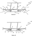
- Figures 1A and 1B are schematic side views of an actuator 10 according to the present invention, figure 1A showing the actuator 10 in an unlocked state, figure 1B showing it in the locked state.
- Actuator 10 comprises a structural frame 11, a movable element 12, wherein the movable element 12 is driven by two antagonistic SMA wires 1 and 2, in particular by their first segments 131, 131' connecting opposite sides of the movable element 12 with different opposite surfaces of frame 11 to alternately drive it along opposite directions according to the different level of actuation of the shape memory alloy wires 1, 2.
- the more the shape memory alloy wires 1, 2 are in their austenite phase (high temperature) with respect to their martensitic phase (low temperature) the higher the traction they will apply to the movable element 12.
- Flexible elements 19, 19' connect another surface of the stationary frame 11 with the movable element 12, to provide a support to the movable element 12 and also guide it in the travel direction while preventing its motion in other directions.
- the actuator locking mechanism is constituted by two movable stoppers 3, 3' that provide a friction-based lock once in contact with the movable element 12, such as in figure 1B , while they do not restrain its movement once they are separated from it, as in figure 1A . If the second segments 132, 132' of the shape memory alloy wires 1, 2 do not exert a force on the movable stoppers 3, 3' via levers 18, 18', the movable stoppers are in contact with the movable element 12 due to the action of springs 15, 15' connecting holders 16, 16' with levers 18, 18'.
- the second segments 132, 132' of the shape memory alloy wires once actuated, pull the movable stoppers 3, 3' away from the movable element 12 and toward resting pillars 17, 17', thus allowing the movement of the movable element 12 driven by the different level of actuation of the shape memory alloy wires 1, 2.
- the shape memory alloy wires first segments 131, 131' are the ones running from the movable element 12 to the nearby frame 11, while the shape memory alloy wires second segments 132, 132' run from said frame 11 to the connecting levers 18, 18'.
- Figures 1A and 1B highlight the key concept of the present invention, namely the fact that it is the activation of the shape memory alloy wires 1 and 2 that determines the unlocking of the movable element 12 by acting on the movable stoppers 3 and 3', whereas the different actuation level of the shape memory alloy, i.e. how much of it is in its austenite phase, will determine the movement (during the temperature transient) and the final position when the pulling wire is at its final temperature.
- the other wire in antagonistic configuration is kept at least at a minimal actuation level, more specifically at an actuation level lower with respect to the pulling wire, to assure that it will disengage the movable element 12 from the frictional lock 3, 3'.
- the decoupling of the locking function from the displacement function for the movable element allows for a more precise control of the movable element position, thus rendering it suitable for the more challenging applications such as, for example, optical zoom function, positioning mechanism for a miniature camera (e.g. for surveillance purposes), miniature robot arm, robotic hand, prosthetic devices.
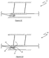
- an actuator according to the present invention may have only one movable stopper, as shown in the schematic side views of figures 1C and ID, in which the actuator structure 10' is the same of figures 1A and 1B apart from the presence of only the left braking "block", i.e. the assembly given by the movable stopper 3, spring 15, holder 16, resting pillar 17, lever 18.
- only shape memory alloy wire 1 through its second segment 132 is responsible through its actuation for disengaging/displacing the movable stopper 3 from the movable element 12, while the movement of the latter is determined by the different level of actuation of the shape memory alloy wires 1, 2.
- the two antagonistic shape memory alloy wires have different lengths, even though it is preferred for them to be of equal length and diameter (i.e. with a difference/tolerance within ⁇ 5%).
- all the embodiments that will be described will have antagonistic shape memory alloy wires of equal length, even though this requirement is not an essential feature.
- the actuators shown in the schematic views of figures 1A-1B and 1C-1D , and more generally in any of the configurations herein described in which a portion of the SMA wire is dedicated to unlocking by acting on one or more movable stoppers, are typically beneficial for high-stroke solutions as the motion range, linked to a specific dedicated portion of the SMA wire, is not reduced by the self-locking capacity; this means that all of the wire length going from the movable element to the actuator frame contributes to the movable element displacement.
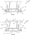
- FIG. 2A Schematic side views of a second embodiment 20 of an actuator according to the present invention are shown in figures 2A and 2B .
- actuator 20 comprises a structural frame 21, a movable element 22, wherein the movable element is driven by two antagonistic SMA wires 1 and 2 with first segments 231, 231' connecting opposite sides of movable element 22 with different opposite surfaces of frame 21 to alternatively drive it along opposite directions.
- Flexible elements 29, 29' connect another surface of stationary frame 21 with movable element 22, to help in supporting it and also to guide it in the direction of travel of the movable element 22 while preventing motion in the other directions.
- Actuator 20 further comprises two spacers/resting pillars 24, 24', two frictional stoppers and movable stoppers 3, 3' that are present on the upper surface of a linking element 27 that ensures a synchronous action of the frictional movable stoppers 3, 3' even when only one of the two shape memory alloy wires 1, 2 is only partially actuated.
- Four lateral springs 25, 25', 25", 25′′′ connect the linking element 27 to holders 26, 26' similarly to springs 15, 15' and holders 16, 16' of the first embodiment.
- Figure 2A represent a situation where no "braking" force is applied to movable element 22, with linking element 27 resting on spacers 24, 24'
- figure 2B represent a situation where linking element 27 is driven to contact the movable element 22, via movable stoppers 3 and 3', and therefore applies a frictional and restraining force to movable element 22.
- the locking/unlocking of the movable element 22 is achieved through the combined action of linking element 27 with movable stoppers 3 and 3', springs 25, 25', 25", 25′′′, levers 28, 28' and holders 26, 26'.
- actuator 30 comprises a movable element 32 connected to two antagonistic shape memory alloy wires 1, 2, each having a first segment 331, 331' and a second segment 332, 332'.
- First segments 331, 331' connect the movable element 32 with a surface of the actuator frame 31 above it, while second segments 332, 332' connect the movable element 32 with levers 38, 38' below it, that are connected to holders 36, 36' through springs 35, 35'.
- the movable frictional stoppers 3 and 3' (located on top of levers 38, 38' at the internal edge thereof) block the displacement of the movable element 32 ( figure 3B ), while once the shape memory alloy wires 1, 2 are actuated, under the traction of their second segments 332, 332', they raise the external edge of levers 38, 38' moving away the frictional stoppers 3 and 3' from the movable element 32 ( figure 3A ), while levers 38, 38' respectively get in contact with end stop elements 34, 34'.
- These element 34, 34' are analogous to the resting pillars 17, 17' of figure 1 and spacers 24, 24' of figure 2 .
- two vertical flexible elements 39, 39' guide the movable element 32 in the direction of travel while preventing movements in unwanted directions (i.e. to avoid rotation).
- actuator 40 comprises a movable element 42 driven by two antagonistic shape memory alloy wires 1, 2 whose central points are connected to the movable element 42 while their extremities are each connected respectively to springs 45, 45', 45", 45′′′ each carrying a movable stopper 3, 3,' 3", 3′′′.
- shape memory alloy wires 1, 2 are connected directly to the actuator frame 41 but they are connected thereto via springs 45, 45', 45", 45′′′ and holders 46, 46', 46", 46′′′ on which said springs are mounted.
- each SMA wire 1, 2 has a first segment 431, 431' and a second segment, 432, 432' that both act on the movable element determining its final position according to the different actuation levels of the shape memory alloy wires 1, 2 while also disengaging ( figure 4A ) the movable frictional stoppers 3, 3', 3", 3′′′ by bringing them in contact with a holder 46, 46', 46", 46′′′.
- the engagement position of figure 4B obviously results from the action of springs 45, 45', 45", 45′′′ upon cooling of the SMA wires 1, 2.
- the present invention is also meant to encompass rotational actuators, i.e. actuators that cause a movable (rotatable) element to rotate under the action of antagonistic shape memory alloy wires and exploiting the same inventive concept of the present invention.
- rotational actuators i.e. actuators that cause a movable (rotatable) element to rotate under the action of antagonistic shape memory alloy wires and exploiting the same inventive concept of the present invention.
- the actuation of the shape memory alloy wires determines the unlocking of the movable (rotatable) element
- the different shape memory alloy actuation levels i.e. how much of it is in its austenite phase, will determine direction and degree of rotation (during the temperature transient) and final position when the wires are at their set temperature, locking in said position when the wires are concurrently cooled to have lock engagement.
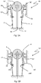
- Actuator 50 comprises a roller 52 (movable element) connected to two antagonistic shape memory alloy wires 1, 2 connected in an unsegmented configuration to opposite sides of roller 52 and to a surface of actuator frame 51 on which roller 52 is mounted via a support 59.
- Two levers 58 and 58' are mounted on opposite side surfaces of frame 51 via springs 55, 55' and are provided with movable stoppers 3, 3' at a top end adjacent to roller 52 and with rolling pins 500, 500' at a bottom end.
- the shape memory alloy wires 1, 2 are interposed respectively between levers 58, 58' and rolling pins 500, 500' such that, when they are actuated, they move stoppers 3, 3' away from roller 52 and toward resting pillars 56, 56' to reach the unlocking position of figure 5A .
- the movement of levers 58, 58' is controlled by springs 55, 55' to restore the locking position of figure 5B .
- actuator 60 comprises a swingable (movable) T-shaped element 62 connected via two L-shaped arms 68, 68' to two shape memory alloy wires 1, 2 connected to a surface of a stationary actuator frame 61, on which the T-shaped element 62 is mounted via a support 69 rotatably connected to the base of the T.
- the two L-shaped arms 68, 68' are connected at one end to two linear springs 65, 65' projecting from the underside of the crossbar of the T-shaped element 62, and at the other end to the SMA wires 1, 2 through movable frictional stoppers 3, 3'.
- Suitable resting elements 67, 67' are preferably present between the corners of arms 68, 68' and element 62, either mounted on the former or on the latter. Control of the engagement/disengagement of the movable frictional stoppers 3, 3' with nearby curved surfaces of the actuator frame 61 is respectively provided by springs 65, 65' and SMA wires 1, 2.
- a seventh embodiment of an actuator according to the present invention is shown in the schematic side views of figures 7A and 7B showing a movable element 72, shaped substantially like a U with a top flange, coupled to a linking frame 77, shaped substantially like a larger U on which the movable element 72 can rest with its top flange through intermediate springs 75, 75', 75", 75′′′.
- the movement of the movable element 72 is controlled by a couple of antagonistic shape memory alloy wires 1, 2 each comprising three segments: a first segment 731, 731' for connecting a surface of a stationary frame 71 with the external top edge of the movable element 72, a second segment 732, 732' for connecting an opposite surface of frame 71 with the external bottom edge of the linking frame 77, and finally a third segment 733, 733' extending between said two segments.
- the locked position of the actuator ( figure 7B ) is achieved when the frictional movable stoppers 3 and 3', mounted under the linking frame 77, are in contact with a surface of frame 71.
- the linking frame 77 is raised so that the movable frictional stoppers 3, 3' are no more in contact with said surface of frame 71 ( figure 7A ).
- flexible elements 79, 79' connect another surface of frame 101, more specifically the opposite surface with respect to the one with which frictional stoppers 3, 3' are in contact in the locked position, with the movable element 72 to provide support and also guide it in the travel direction while preventing its motion in other directions.
- the linking frame 77 is taking care of the displacement of the movable stoppers, so that the movable element 72 just undergoes the lateral shift without the need of a vertical (secondary/parasitic) displacement of the movable element 72 in order to engage/disengage the movable stoppers 3, 3'.
- the present invention is not limited to any specific shape or geometry for the movable element.
- the guiding means of the movable element can not only comprise flexible elements, but also for example sliding or roller bearings.
- the invention is not limited to any specific shape memory alloy material, even though preferred are Ni-Ti based alloys such as Nitinol described in US patents US8152941 , US9315880 , US8430981 .
- Nitinol may exhibit alternately superelastic wire behavior or shape memory alloy behavior according to its processing.
- the properties of Nitinol and methods allowing to achieve them are widely known to those skilled in the art, see e.g. the article " A Study of the Properties of a High Temperature Binary Nitinol Alloy Above and Below its Martensite to Austenite Transformation Temperature” by Dennis W. Norwich presented at the SMST 2010 conference .
- Nitinol may be used as such or its characteristics in terms of transition temperature may be tailored by adding elements such as Hf, Nb, Pt, Cu.
- the proper choice of material alloy and its characteristics are commonly known to a person skilled in the art, see for example: http://memry.com/nitinol-iq/nitinol-fundamentals/transformation-temperatures
- the shape memory alloy wires may be used "per se” or with a coating/sheath to improve their thermal management, i.e. their cooling after being actuated.
- the coating sheath may be uniform, such as described in the US patent 9068561 that teaches how to manage residual heat by resorting to an electrically insulating coating which is a heat conductor, while US patent 6835083 describes a shape memory alloy wire having an enclosing sheath capable to improve cooling after every actuation cycle.
- a coating with a suitable dispersion of phase changing materials such as described in WO 2019/003198 in the applicant's name, may be advantageously employed.
- shape memory alloy wire diameter it is advantageously comprised between 20 ⁇ m and 200 ⁇ m. It is also important to underline that as the shape memory alloy wires are real objects, departing from a circular section is possible, so the term "diameter" is to be intended as the diameter of the smallest enclosing circle.
Landscapes
- Engineering & Computer Science (AREA)
- Chemical & Material Sciences (AREA)
- Combustion & Propulsion (AREA)
- Mechanical Engineering (AREA)
- General Engineering & Computer Science (AREA)
- Physics & Mathematics (AREA)
- General Physics & Mathematics (AREA)
- Optics & Photonics (AREA)
- Control Of Position Or Direction (AREA)
- Adjustment Of Camera Lenses (AREA)
- Manipulator (AREA)
Description
- The present invention is inherent to a multi-stable shape memory alloy (SMA) actuator exploiting the property of shape memory alloy wires used in antagonistic configuration. Generally speaking, actuators based on shape memory alloy wires present various advantages such as reduced encumbrance, weight, power consumption, all of the above leading to the possibility of achieving a high degree of miniaturization or ease of integration in more complex systems/devices.
- Some examples of recent SMA wire-based actuators are shown in the
US patent applications 2006/9298500 ,2005/0160858 andUS patent 7364211 . All the devices shown in these references suffer from the drawback that the actuator has only two stable positions that a kind of mechanical lock coupled with the SMA active component (the wire) ensures without the need to supply power/current. - A SMA based actuator using two shape memory alloy wires acting in antagonistic configuration on a rotatable and linearly displaceable element is described in the
US patent application 2008/0271559 . In the described solution the movable element needs to undergo a "spurious"/"parasitic" secondary movement not related to the displacement required for actuation. This characteristic renders the described solution not compatible with the most demanding applications, for example such spurious movement in an optical zoom would lead to a serious deterioration of image quality in camera modules, more specifically image quality would be acceptable only in a locked state of the actuator. - Purpose of the present invention is to provide an actuator based on the use of shape memory alloy wires capable to overcome the limit of the prior art, more specifically not being limited in the number of achievable stable positions while still not requiring any power/current supply for the maintenance of such stable positions, and in a first aspect thereof consists in a shape memory alloy actuator comprising the features of
independent claim 1. - The invention will be further illustrated with the help of the following figures where:
-
Figures 1A and 1B are schematic side views of a first embodiment of an actuator according to the present invention, while schematic side views of a variant of this first embodiment are shown infigures 1C and 1D , -
Figures 2A and 2B are schematic side views of a second embodiment of an actuator according to the present invention, -
Figures 3A and 3B are schematic side views of a third embodiment of an actuator according to the present invention, -
Figures 4A and 4B are schematic side views of a fourth embodiment of an actuator according to the present invention, -
Figures 5A and 5B are schematic side views of a fifth embodiment of an actuator according to the present invention, -
Figures 6A and 6B are schematic side views of a sixth embodiment of an actuator according to the present invention, and -
Figures 7A and 7B are schematic side views of a seventh embodiment of an actuator according to the present invention. - In the figures, the size and the dimensional ratios of the various elements shown in some cases have been altered in order to help understanding the drawings, with particular but not exclusive reference to the SMA wire diameter with respect to other elements of the actuator; also, some ancillary elements not necessary for the invention understanding, such as current supply source, wire crimping/fixing elements, etc. have not been shown since they are ordinary means known in the technical field.
- A common inventive feature linking all of the embodiments of the present invention is the use of at least two shape memory alloy wires in antagonistic configuration where locking, unlocking and movement of the movable element are determined by the different degree of actuation of the shape memory alloy wires. More specifically if no power supply is provided there is a lock engagement that prevents the movement, while disengagement is given by heating at least one of the shape memory alloy wires, even though the final position is determined by the equilibrium resulting from the different pulling of the SMA wires (i.e. their different degree of actuation resulting from their different temperature). Once at the desired position, concurrent cooling provides for keeping the reached position and at the same time allows for lock engagement due to the action of a return mechanism, and therefore no further actuated mechanism for locking/unlocking the movable element is needed.
-
Figures 1A and 1B are schematic side views of anactuator 10 according to the present invention,figure 1A showing theactuator 10 in an unlocked state,figure 1B showing it in the locked state. -
Actuator 10 comprises astructural frame 11, amovable element 12, wherein themovable element 12 is driven by twoantagonistic SMA wires first segments 131, 131' connecting opposite sides of themovable element 12 with different opposite surfaces offrame 11 to alternately drive it along opposite directions according to the different level of actuation of the shapememory alloy wires memory alloy wires movable element 12. Details of operating principles of shape memory alloy wires are widely known to a person of ordinary skill in the art, see for example the paper "Fundamental characteristics and design method for nickel-titanium shape memory", published in 2001 on PERIODICA POLYTECHNICA SER. MECH. ENG. VOL. 45, NO. 1, PP. 75-86. -
Flexible elements 19, 19' connect another surface of thestationary frame 11 with themovable element 12, to provide a support to themovable element 12 and also guide it in the travel direction while preventing its motion in other directions. - The actuator locking mechanism is constituted by two
movable stoppers 3, 3' that provide a friction-based lock once in contact with themovable element 12, such as infigure 1B , while they do not restrain its movement once they are separated from it, as infigure 1A . If thesecond segments 132, 132' of the shapememory alloy wires movable stoppers 3, 3' vialevers 18, 18', the movable stoppers are in contact with themovable element 12 due to the action ofsprings 15, 15' connecting holders 16, 16' withlevers 18, 18'. Thesecond segments 132, 132' of the shape memory alloy wires, once actuated, pull themovable stoppers 3, 3' away from themovable element 12 and toward restingpillars 17, 17', thus allowing the movement of themovable element 12 driven by the different level of actuation of the shapememory alloy wires - For the sake of clarity, the shape memory alloy wires
first segments 131, 131' are the ones running from themovable element 12 to thenearby frame 11, while the shape memory alloy wiressecond segments 132, 132' run fromsaid frame 11 to the connectinglevers 18, 18'. -
Figures 1A and 1B highlight the key concept of the present invention, namely the fact that it is the activation of the shapememory alloy wires movable element 12 by acting on themovable stoppers 3 and 3', whereas the different actuation level of the shape memory alloy, i.e. how much of it is in its austenite phase, will determine the movement (during the temperature transient) and the final position when the pulling wire is at its final temperature. The other wire in antagonistic configuration is kept at least at a minimal actuation level, more specifically at an actuation level lower with respect to the pulling wire, to assure that it will disengage themovable element 12 from thefrictional lock 3, 3'. The decoupling of the locking function from the displacement function for the movable element allows for a more precise control of the movable element position, thus rendering it suitable for the more challenging applications such as, for example, optical zoom function, positioning mechanism for a miniature camera (e.g. for surveillance purposes), miniature robot arm, robotic hand, prosthetic devices. - It is to be underlined that an actuator according to the present invention may have only one movable stopper, as shown in the schematic side views of
figures 1C and ID, in which the actuator structure 10' is the same offigures 1A and 1B apart from the presence of only the left braking "block", i.e. the assembly given by themovable stopper 3,spring 15,holder 16, restingpillar 17,lever 18. In this case, only shapememory alloy wire 1, through itssecond segment 132, is responsible through its actuation for disengaging/displacing themovable stopper 3 from themovable element 12, while the movement of the latter is determined by the different level of actuation of the shapememory alloy wires - As exemplified in the embodiment shown in
figures 1C-1D , it is possible that the two antagonistic shape memory alloy wires have different lengths, even though it is preferred for them to be of equal length and diameter (i.e. with a difference/tolerance within ±5%). In the following, all the embodiments that will be described will have antagonistic shape memory alloy wires of equal length, even though this requirement is not an essential feature. - The actuators shown in the schematic views of
figures 1A-1B and1C-1D , and more generally in any of the configurations herein described in which a portion of the SMA wire is dedicated to unlocking by acting on one or more movable stoppers, are typically beneficial for high-stroke solutions as the motion range, linked to a specific dedicated portion of the SMA wire, is not reduced by the self-locking capacity; this means that all of the wire length going from the movable element to the actuator frame contributes to the movable element displacement. - Schematic side views of a
second embodiment 20 of an actuator according to the present invention are shown infigures 2A and 2B . - Similarly to
actuator 10,actuator 20 comprises astructural frame 21, amovable element 22, wherein the movable element is driven by twoantagonistic SMA wires first segments 231, 231' connecting opposite sides ofmovable element 22 with different opposite surfaces offrame 21 to alternatively drive it along opposite directions.Flexible elements 29, 29' connect another surface ofstationary frame 21 withmovable element 22, to help in supporting it and also to guide it in the direction of travel of themovable element 22 while preventing motion in the other directions. -
Actuator 20 further comprises two spacers/resting pillars 24, 24', two frictional stoppers andmovable stoppers 3, 3' that are present on the upper surface of a linkingelement 27 that ensures a synchronous action of the frictionalmovable stoppers 3, 3' even when only one of the two shapememory alloy wires lateral springs element 27 toholders 26, 26' similarly tosprings 15, 15' andholders 16, 16' of the first embodiment. - Vertical positioning of the linking
element 27 is regulated bylevers 28, 28' controlled by thesecond segments 232, 232' of the shape memory alloy wires, said levers 28, 28' acting on the twoupper springs 25" and 25‴, whereas the other twolower springs 25, 25'are not lever-controlled and help in guiding the linkingelement 27 in a direction perpendicular to the displacement of themovable element 22 to prevent a rotation of the linkingelement 27.Figure 2A represent a situation where no "braking" force is applied tomovable element 22, with linkingelement 27 resting onspacers 24, 24', whilefigure 2B represent a situation where linkingelement 27 is driven to contact themovable element 22, viamovable stoppers 3 and 3', and therefore applies a frictional and restraining force tomovable element 22. In this case, the locking/unlocking of themovable element 22 is achieved through the combined action of linkingelement 27 withmovable stoppers 3 and 3',springs holders 26, 26'. - A third embodiment according to the present invention is shown in the schematic views of
figures 3A and 3B . In thiscase actuator 30 comprises amovable element 32 connected to two antagonistic shapememory alloy wires first segment 331, 331' and asecond segment 332, 332'.First segments 331, 331' connect themovable element 32 with a surface of theactuator frame 31 above it, whilesecond segments 332, 332' connect themovable element 32 withlevers 38, 38' below it, that are connected toholders 36, 36' throughsprings 35, 35'. - If the shape
memory alloy wires frictional stoppers 3 and 3' (located on top oflevers 38, 38' at the internal edge thereof) block the displacement of the movable element 32 (figure 3B ), while once the shapememory alloy wires second segments 332, 332', they raise the external edge oflevers 38, 38' moving away thefrictional stoppers 3 and 3' from the movable element 32 (figure 3A ), whilelevers 38, 38' respectively get in contact withend stop elements 34, 34'. Theseelement 34, 34' are analogous to the restingpillars 17, 17' offigure 1 andspacers 24, 24' offigure 2 . Also in this embodiment, two verticalflexible elements 39, 39' guide themovable element 32 in the direction of travel while preventing movements in unwanted directions (i.e. to avoid rotation). - A fourth embodiment according to the present invention is shown in the schematic views of
figures 4A and 4B . In thiscase actuator 40 comprises amovable element 42 driven by two antagonistic shapememory alloy wires movable element 42 while their extremities are each connected respectively tosprings movable stopper memory alloy wires actuator frame 41 but they are connected thereto viasprings holders - In this embodiment each
SMA wire memory alloy wires figure 4A ) the movablefrictional stoppers holder figure 4B obviously results from the action ofsprings SMA wires - The present invention is also meant to encompass rotational actuators, i.e. actuators that cause a movable (rotatable) element to rotate under the action of antagonistic shape memory alloy wires and exploiting the same inventive concept of the present invention. In other words, the actuation of the shape memory alloy wires determines the unlocking of the movable (rotatable) element, whereas the different shape memory alloy actuation levels, i.e. how much of it is in its austenite phase, will determine direction and degree of rotation (during the temperature transient) and final position when the wires are at their set temperature, locking in said position when the wires are concurrently cooled to have lock engagement.
- An exemplary embodiment of a rotatable actuator according to the present invention is shown in the schematic side views of
figures 5A and 5B .Actuator 50 comprises a roller 52 (movable element) connected to two antagonistic shapememory alloy wires roller 52 and to a surface ofactuator frame 51 on whichroller 52 is mounted via asupport 59. - Two
levers 58 and 58' are mounted on opposite side surfaces offrame 51 viasprings 55, 55' and are provided withmovable stoppers 3, 3' at a top end adjacent toroller 52 and withrolling pins 500, 500' at a bottom end. The shapememory alloy wires levers 58, 58' and rollingpins 500, 500' such that, when they are actuated, they movestoppers 3, 3' away fromroller 52 and toward restingpillars 56, 56' to reach the unlocking position offigure 5A . Upon cooling of theSMA wires levers 58, 58' is controlled bysprings 55, 55' to restore the locking position offigure 5B . - A sixth embodiment for a further rotatable actuator according to the present invention is shown in the schematic side views of
figures 6A and 6B . In this case,actuator 60 comprises a swingable (movable) T-shapedelement 62 connected via two L-shapedarms 68, 68' to two shapememory alloy wires stationary actuator frame 61, on which the T-shapedelement 62 is mounted via asupport 69 rotatably connected to the base of the T. The two L-shapedarms 68, 68' are connected at one end to twolinear springs 65, 65' projecting from the underside of the crossbar of the T-shapedelement 62, and at the other end to theSMA wires frictional stoppers 3, 3'.Suitable resting elements 67, 67' are preferably present between the corners ofarms 68, 68' andelement 62, either mounted on the former or on the latter. Control of the engagement/disengagement of the movablefrictional stoppers 3, 3' with nearby curved surfaces of theactuator frame 61 is respectively provided bysprings 65, 65' andSMA wires - A seventh embodiment of an actuator according to the present invention is shown in the schematic side views of
figures 7A and 7B showing amovable element 72, shaped substantially like a U with a top flange, coupled to a linkingframe 77, shaped substantially like a larger U on which themovable element 72 can rest with its top flange throughintermediate springs movable element 72 is controlled by a couple of antagonistic shapememory alloy wires stationary frame 71 with the external top edge of themovable element 72, a second segment 732, 732' for connecting an opposite surface offrame 71 with the external bottom edge of the linkingframe 77, and finally a third segment 733, 733' extending between said two segments. - The locked position of the actuator (
figure 7B ) is achieved when the frictionalmovable stoppers 3 and 3', mounted under the linkingframe 77, are in contact with a surface offrame 71. Upon actuation of the shape memory alloy wires, more specifically thanks to the third segments 733, 733' of the shape memory alloy wires, the linkingframe 77 is raised so that the movablefrictional stoppers 3, 3' are no more in contact with said surface of frame 71 (figure 7A ). - Similarly to
figures 1A-1B ,flexible elements 79, 79' connect another surface of frame 101, more specifically the opposite surface with respect to the one with whichfrictional stoppers 3, 3' are in contact in the locked position, with themovable element 72 to provide support and also guide it in the travel direction while preventing its motion in other directions. - As in the case of the second embodiment of
figures 2A-2B , the linkingframe 77 is taking care of the displacement of the movable stoppers, so that themovable element 72 just undergoes the lateral shift without the need of a vertical (secondary/parasitic) displacement of themovable element 72 in order to engage/disengage themovable stoppers 3, 3'. - As it is possible to appreciate by comparing the depiction of the movable elements in all the figures, the present invention is not limited to any specific shape or geometry for the movable element.
- It is to be underlined that the embodiments shown in the previous figures are only exemplary of the scope of the present invention that is not limited to the embodiments illustrated in those figures but also encompasses other immediate variants, for example the shape memory alloy wires do not need to be identical in terms of length, diameter, composition or positioning and they could be asymmetrical, as previously mentioned.
- With regards to the return elements (15, 15', ...75", 75‴) depicted in the various embodiments shown, preferred is the use of thin flexible elements (flexures), even though classic springs or other types of elastic elements, such as rubbers or elastomeric cushions may be used. Other passive elements for the movable element lock positioning may also be employed, such as, for example, permanent magnets in combination with ferromagnetic elements. When a bi-stable mechanism in the return element is being used, no minimum tension in the SMA wires needs to be maintained while positioning the movable element. All of the previous is commonly known to a person skilled in the art, for example suitable bi-stable mechanisms can be found in the 1994 book edited by Springer-Verlag "Konstruieren mit Konstruktionskatalogen. Band 2: Kataloge".
- The examples in the figures generally use frictional contact locking of the movable element but form-locking contacting surfaces, yielding higher holding forces while restricting the number of possible locking positions of the movable element, may be employed instead. It is also essential for achieving the advantages of the present invention (suppression of a secondary movement) that the coupling of the movable element with a surface of the stationary frame through the movable stopper(s) to achieve locking is obtained indirectly, through a locking mechanism mounted on the return mechanism that provides the restoring force for the lock engagement (
e.g. elements - The guiding means of the movable element can not only comprise flexible elements, but also for example sliding or roller bearings.
- The invention is not limited to any specific shape memory alloy material, even though preferred are Ni-Ti based alloys such as Nitinol described in
US patents US8152941 ,US9315880 US8430981 . - Nitinol may exhibit alternately superelastic wire behavior or shape memory alloy behavior according to its processing. The properties of Nitinol and methods allowing to achieve them are widely known to those skilled in the art, see e.g. the article "A Study of the Properties of a High Temperature Binary Nitinol Alloy Above and Below its Martensite to Austenite Transformation Temperature" by Dennis W. Norwich presented at the SMST 2010 conference.
- Nitinol may be used as such or its characteristics in terms of transition temperature may be tailored by adding elements such as Hf, Nb, Pt, Cu. The proper choice of material alloy and its characteristics are commonly known to a person skilled in the art, see for example:
http://memry.com/nitinol-iq/nitinol-fundamentals/transformation-temperatures - Also the shape memory alloy wires may be used "per se" or with a coating/sheath to improve their thermal management, i.e. their cooling after being actuated. The coating sheath may be uniform, such as described in the
US patent 9068561 US patent 6835083 describes a shape memory alloy wire having an enclosing sheath capable to improve cooling after every actuation cycle. Also a coating with a suitable dispersion of phase changing materials, such as described inWO 2019/003198 in the applicant's name, may be advantageously employed. - With regards to the shape memory alloy wire diameter, it is advantageously comprised between 20 µm and 200 µm. It is also important to underline that as the shape memory alloy wires are real objects, departing from a circular section is possible, so the term "diameter" is to be intended as the diameter of the smallest enclosing circle.
Claims (12)
- A shape memory alloy actuator (10; 10'; 20; 30; 40; 50; 60; 70) comprising a movable element (12; 22; 32; 42; 52; 62; 72) driven by at least first (1) and second (2) shape memory alloy wires arranged in an antagonistic configuration and concurrently determining the position of said movable element (12; 22; 32; 42; 52; 62; 72), a stationary frame (11; 21; 31; 41; 51; 61; 71), a locking mechanism to lock the movable element (12; 22; 32; 42; 52; 62; 72) by indirectly coupling a surface of said stationary frame (11; 21; 31; 41; 51; 61; 71) with the movable element (12; 22; 32; 42; 52; 62; 72), said indirect coupling being achieved through said locking mechanism, and at least one return mechanism that provides the restoring force for the lock engagement, characterized in that the locking mechanism includes at least one movable stopper (3, 3', 3", 3‴) that is movable between a locking position in which it engages either the movable element (12; 22; 32; 42; 52) or said surface of the stationary frame (61; 71) and an unlocking position in which it does not engage either of them, said locking mechanism being mounted on said at least one return mechanism that provides the restoring force for the lock engagement, the disengagement of the at least one movable stopper (3, 3', 3", 3‴) being controlled by the actuation of at least one of said first (1) and second (2) shape memory alloy wires and its engagement being automatically performed by the restoring force provided by the at least one return mechanism upon cooling of the shape memory alloy wires (1, 2) as a consequence of said cooling.
- A shape memory alloy actuator according to claim 1, wherein all the shape memory alloy wires (1, 2) have equal length and diameter.
- A shape memory alloy actuator according to any of the previous claims, wherein the movement imparted to the movable element (12; 22; 32, 42; 52; 62; 72) by the actuation of said at least first (1) and second (2) shape memory alloy wires is linear or rotary or a combination thereof.
- A shape memory alloy actuator according to any of the previous claims, wherein each of said first (1) and second (2) shape memory alloy wires comprises a first segment (131, 131'; 231, 231'; 431, 431') and a second segment (132, 132'; 232, 232'; 432, 432'), wherein the first segments (131, 131'; 231, 231'; 431, 431') concurrently drive the movement of the movable element (12; 22; 32; 42), and the disengagement of said at least one movable stopper (3, 3') is controlled by at least one of said first (131, 131'; 231, 231'; 431, 431') and second segments (132, 132'; 232, 232'; 432, 432').
- A shape memory alloy actuator (40) according to claim 3, wherein each of said first (1) and second (2) shape memory alloy wires comprises a first segment (431, 431') and a second segment (432, 432') and both said first segments (431, 431') and second segments (432, 432') concurrently drive the movable element (42) and control the disengagement of a plurality of movable stoppers (3, 3', 3", 3‴).
- A shape memory alloy actuator (50; 60) according to claim 3, wherein said first (1) and second (2) shape memory alloy wires are unsegmented wires directly connecting the movable element (52; 62) with the actuator frame (51; 61).
- A shape memory alloy actuator (20; 70) according to claim 3, wherein it comprises a linking element (27; 77) physically connecting several stoppers (3, 3') with each other.
- A shape memory alloy actuator (10; 10'; 20; 30) according to claim 3, wherein one or more elastic elements (19, 19'; 29, 29'; 39, 39'), rolling bearings or sliding bearings connect the movable element (12; 22; 32) with a surface of the stationary frame (11; 21; 31).
- A shape memory alloy actuator according to any of the previous claims, wherein the return mechanism for the engagement of the movable stoppers (3, 3', 3", 3‴) comprises elastic elements (15, 15'; 25, 25', 25", 25‴; 35, 35'; 45, 45', 45", 45‴; 55, 55'; 65, 65'; 75, 75', 75", 75‴).
- A shape memory alloy actuator according to any of claims 1 to 8, wherein the return mechanism for the engagement of the movable stoppers (3, 3', 3", 3‴) comprises one or more magnets, preferably permanent magnets.
- A shape memory alloy actuator according to any of the previous claims, wherein the return mechanism for the engagement of the movable stoppers (3, 3', 3", 3‴) comprises one or more bi-stable elements.
- A shape memory alloy actuator according to any of the previous claims, wherein said movable stoppers (3, 3', 3", 3‴) are chosen from frictional stoppers and form factor stoppers.
Applications Claiming Priority (2)
| Application Number | Priority Date | Filing Date | Title |
|---|---|---|---|
| IT102019000003589A IT201900003589A1 (en) | 2019-03-12 | 2019-03-12 | Multi-stable actuator based on shape memory alloy wires |
| PCT/IB2020/052056 WO2020183360A1 (en) | 2019-03-12 | 2020-03-10 | Multi-stable actuator based on shape memory alloy wires |
Publications (2)
| Publication Number | Publication Date |
|---|---|
| EP3908753A1 EP3908753A1 (en) | 2021-11-17 |
| EP3908753B1 true EP3908753B1 (en) | 2022-08-10 |
Family
ID=66641404
Family Applications (1)
| Application Number | Title | Priority Date | Filing Date |
|---|---|---|---|
| EP20713745.6A Active EP3908753B1 (en) | 2019-03-12 | 2020-03-10 | Multi-stable actuator based on shape memory alloy wires |
Country Status (8)
| Country | Link |
|---|---|
| US (1) | US11927180B2 (en) |
| EP (1) | EP3908753B1 (en) |
| JP (1) | JP7433334B2 (en) |
| KR (1) | KR102573544B1 (en) |
| CN (1) | CN113474552B (en) |
| IT (1) | IT201900003589A1 (en) |
| TW (1) | TWI848072B (en) |
| WO (1) | WO2020183360A1 (en) |
Families Citing this family (21)
| Publication number | Priority date | Publication date | Assignee | Title |
|---|---|---|---|---|
| IT201900025057A1 (en) | 2019-12-20 | 2021-06-20 | Actuator Solutions GmbH | Discrete actuator based on shape memory alloy |
| US11460009B1 (en) | 2021-03-22 | 2022-10-04 | Toyota Motor Engineering & Manufacturing North America, Inc. | Actuator for holding an object |
| US11472325B1 (en) | 2021-03-30 | 2022-10-18 | Toyota Motor Engineering & Manufacturing North America, Inc. | Actuator for a support system of a seat |
| IT202100010589A1 (en) * | 2021-04-27 | 2022-10-27 | Actuator Solutions GmbH | SHAPE MEMORY ALLOY DRIVEN FLUID SUBASSEMBLY AND EQUIPMENT INCORPORATING IT |
| CN113161179B (en) * | 2021-04-29 | 2023-03-21 | 维沃移动通信有限公司 | Lifting key and electronic equipment |
| EP4158194B1 (en) | 2021-08-13 | 2023-07-19 | Actuator Solutions GmbH | Actuator subassembly controlled by shape memory alloy wires, system comprising a plurality of such subassemblies and control method for such system |
| CN216774836U (en) * | 2021-09-13 | 2022-06-17 | 格科微电子(上海)有限公司 | Optical anti-shake device and camera module |
| US11649808B2 (en) | 2021-10-20 | 2023-05-16 | Toyota Motor Engineering & Manufacturing North America, Inc. | Multi-stable actuator |
| US12410782B2 (en) | 2021-11-24 | 2025-09-09 | Cambridge Mechatronics Limited | Actuator assembly |
| GB2629264B (en) * | 2021-12-22 | 2025-09-24 | Cambridge Mechatronics Ltd | Actuator assembly |
| US12383066B2 (en) | 2022-04-26 | 2025-08-12 | Toyota Motor Engineering & Manufacturing North America, Inc. | Chair with shape memory material-based movement synchronized with visual content |
| US12330301B2 (en) * | 2022-11-18 | 2025-06-17 | Zebra Technologies Corporation | Shape-memory effector assemblies with integrated position sensing |
| US20240262045A1 (en) * | 2023-02-08 | 2024-08-08 | The Boeing Company | Apparatuses, tacking sticks, and systems for tacking workpieces in composite manufacturing and methods associated therewith |
| US12241458B2 (en) | 2023-02-16 | 2025-03-04 | Toyota Motor Engineering & Manufacturing North America, Inc. | Actuator with contracting member |
| US12270386B2 (en) | 2023-02-16 | 2025-04-08 | Toyota Motor Engineering & Manufacturing North America, Inc. | Shape memory material member-based actuator |
| CN120641656A (en) * | 2023-02-17 | 2025-09-12 | 剑桥机电有限公司 | Actuator assembly |
| US12152570B2 (en) | 2023-02-22 | 2024-11-26 | Toyota Motor Engineering & Manufacturing North America, Inc. | Shape memory material member-based actuator with electrostatic clutch preliminary class |
| US12163507B2 (en) | 2023-02-22 | 2024-12-10 | Toyota Motor Engineering & Manufacturing North America, Inc. | Contracting member-based actuator with clutch |
| US12234811B1 (en) | 2023-08-21 | 2025-02-25 | Toyota Motor Engineering & Manufacturing North America, Inc. | Monitoring a state of a shape memory material member |
| GB2632836A (en) * | 2023-08-22 | 2025-02-26 | Cambridge Mechatronics Ltd | SMA actuator assembly |
| US12589512B2 (en) | 2023-12-28 | 2026-03-31 | Toyota Motor Engineering & Manufacturing North America, Inc. | Shearing tool with closure assist |
Citations (1)
| Publication number | Priority date | Publication date | Assignee | Title |
|---|---|---|---|---|
| EP3650691A1 (en) * | 2018-11-07 | 2020-05-13 | L&P Property Management Company | Actuator device using shape memory alloy element |
Family Cites Families (25)
| Publication number | Priority date | Publication date | Assignee | Title |
|---|---|---|---|---|
| IT1293669B1 (en) * | 1997-08-01 | 1999-03-08 | Fiat Ricerche | CONTROL DEVICE FOR A SWIVELLING DEFLECTOR, PARTICULARLY FOR A MOTOR VEHICLE AIR CONDITIONING SYSTEM. |
| EP1364125A1 (en) * | 2001-01-17 | 2003-11-26 | M 2 Medical A/S | Shape memory alloy actuator |
| US20050160858A1 (en) | 2002-07-24 | 2005-07-28 | M 2 Medical A/S | Shape memory alloy actuator |
| JP4233290B2 (en) | 2002-09-09 | 2009-03-04 | トキコーポレーション株式会社 | Shape memory alloy actuator |
| ITTO20030045A1 (en) | 2003-01-28 | 2004-07-29 | Fiat Ricerche | FLEXIBLE CABLE MEMORY ACTUATOR DEVICE |
| US6880336B2 (en) * | 2003-08-20 | 2005-04-19 | Lockheed Martin Corporation | Solid state thermal engine |
| US7364211B2 (en) | 2003-11-13 | 2008-04-29 | Intier Automotive Closures Inc. | Vehicle lock controlled by a shape memory alloy actuator |
| FR2862353B1 (en) | 2003-11-17 | 2007-08-17 | Commissariat Energie Atomique | MULTI-STABLE SHAPE MEMORY ALLOY ACTUATOR AND TOUCH INTERFACE IMPLEMENTING THE SAME |
| US20060029850A1 (en) | 2004-08-03 | 2006-02-09 | Peter Szrama | Fuel cell assembly with structural film |
| DE102005059081A1 (en) * | 2005-08-11 | 2007-02-22 | Alfmeier Präzision AG Baugruppen und Systemlösungen | Shape memory alloy actuator has rotary axis for rotary drive element and two driven elements with shape memory alloy wires to produce torque around axis |
| US20080271559A1 (en) * | 2005-08-11 | 2008-11-06 | Alfmeier Prazision Ag Baugruppen Und Systemlosungen | Turn-actuator with tensile element of shape memory alloy |
| DE112006002705T5 (en) * | 2005-10-12 | 2008-08-21 | Magna Closures Inc., Newmarket | Closure rotary actuator |
| US7878459B2 (en) * | 2007-06-29 | 2011-02-01 | The Boeing Company | Aircraft systems with shape memory alloy (SMA) actuators, and associated methods |
| DE102007053741B4 (en) * | 2007-11-12 | 2020-01-30 | ABUS Seccor GmbH | Electronic locking system with memory metal actuator |
| US8152941B2 (en) | 2009-11-02 | 2012-04-10 | Saes Smart Materials | Ni-Ti semi-finished products and related methods |
| DE102010038700B4 (en) * | 2010-07-30 | 2021-04-29 | Kiekert Aktiengesellschaft | Actuator with shape memory alloy |
| JP5878869B2 (en) | 2010-08-20 | 2016-03-08 | 株式会社青電舎 | Shock-driven actuator |
| US8430981B1 (en) | 2012-07-30 | 2013-04-30 | Saes Smart Materials | Nickel-titanium Alloys, related products and methods |
| ITMI20121988A1 (en) * | 2012-11-22 | 2014-05-23 | Getters Spa | ACTUATOR ELEMENT WITH IMPROVED FATIGUE RESISTANCE MADE OF A FORM MEMORY LEAGUE |
| ITMI20130512A1 (en) | 2013-04-05 | 2014-10-06 | Getters Spa | SHAPED MEMORY ACTUATOR WITH MULTISTABLE CONTROL PARTS |
| CN104753303B (en) * | 2013-12-31 | 2018-10-02 | 博立码杰通讯(深圳)有限公司 | Driving device and device manufacture method |
| US9424722B2 (en) * | 2014-05-14 | 2016-08-23 | Unlimited Liability, LLC | Smart memory material lock devices |
| JP6187702B2 (en) * | 2014-09-02 | 2017-08-30 | 株式会社村田製作所 | Drive device |
| CN107111212B (en) * | 2014-11-12 | 2019-11-12 | 艾斯科技公司 | Camera module autofocus actuator and control method thereof |
| IT201700073563A1 (en) | 2017-06-30 | 2018-12-30 | Getters Spa | SETS ACTUATORS INCLUDING WIRES ALLOY WITH SHAPE MEMORY AND COATINGS WITH PHASE-MADE MATERIALS PARTICLES |
-
2019
- 2019-03-12 IT IT102019000003589A patent/IT201900003589A1/en unknown
-
2020
- 2020-03-10 US US17/431,726 patent/US11927180B2/en active Active
- 2020-03-10 WO PCT/IB2020/052056 patent/WO2020183360A1/en not_active Ceased
- 2020-03-10 KR KR1020217026862A patent/KR102573544B1/en active Active
- 2020-03-10 JP JP2021550042A patent/JP7433334B2/en active Active
- 2020-03-10 CN CN202080016705.6A patent/CN113474552B/en active Active
- 2020-03-10 EP EP20713745.6A patent/EP3908753B1/en active Active
- 2020-03-11 TW TW109108000A patent/TWI848072B/en active
Patent Citations (1)
| Publication number | Priority date | Publication date | Assignee | Title |
|---|---|---|---|---|
| EP3650691A1 (en) * | 2018-11-07 | 2020-05-13 | L&P Property Management Company | Actuator device using shape memory alloy element |
Also Published As
| Publication number | Publication date |
|---|---|
| CN113474552B (en) | 2023-12-12 |
| WO2020183360A1 (en) | 2020-09-17 |
| US20220136488A1 (en) | 2022-05-05 |
| CN113474552A (en) | 2021-10-01 |
| JP7433334B2 (en) | 2024-02-19 |
| TWI848072B (en) | 2024-07-11 |
| EP3908753A1 (en) | 2021-11-17 |
| TW202045815A (en) | 2020-12-16 |
| JP2022524954A (en) | 2022-05-11 |
| KR20210134631A (en) | 2021-11-10 |
| US11927180B2 (en) | 2024-03-12 |
| IT201900003589A1 (en) | 2020-09-12 |
| KR102573544B1 (en) | 2023-09-01 |
Similar Documents
| Publication | Publication Date | Title |
|---|---|---|
| US11927180B2 (en) | Multi-stable actuator based on shape memory alloy wires | |
| WO2023084251A1 (en) | An actuator assembly | |
| US11578709B2 (en) | SMA-based discrete actuator | |
| US20260036116A1 (en) | An actuator assembly | |
| JP2022524954A5 (en) | ||
| CN116635626A (en) | actuator assembly | |
| US20080307786A1 (en) | Multi-Stable Actuator Based on Shape Memory Alloy and Touch-Sensitive Interface Using Same | |
| US9447854B2 (en) | Force transfer mechanism | |
| EP4515103A1 (en) | Actuator assembly | |
| EP4587704A1 (en) | Actuator assembly | |
| US7504921B2 (en) | Stepping flexures | |
| WO2015130649A1 (en) | Circuit interruption device employing shape memory alloy element | |
| US7963360B2 (en) | Ratchet reset mechanism | |
| US11815072B2 (en) | Thermal actuator arrangement having improved reset time | |
| US20200256090A1 (en) | Swing type sma actuator | |
| JP4774437B2 (en) | Energy storage device | |
| JPH04218981A (en) | Displacement expansion mechanism of piezoelectric actuator | |
| US11725715B1 (en) | Advance and hold pawl actuator | |
| WO2025040908A1 (en) | Actuator assembly | |
| US9531302B1 (en) | Racheting micromotor using bi-directional actuator | |
| GB2622421A (en) | Actuator assembly | |
| Ouwehand | Novel nanometer precision planar positioning stage using pre-sliding friction | |
| US11454048B2 (en) | Shape memory alloy locking apparatuses | |
| US6098485A (en) | Lead screw actuator | |
| WO2025027311A1 (en) | Variable aperture assembly |
Legal Events
| Date | Code | Title | Description |
|---|---|---|---|
| STAA | Information on the status of an ep patent application or granted ep patent |
Free format text: STATUS: UNKNOWN |
|
| STAA | Information on the status of an ep patent application or granted ep patent |
Free format text: STATUS: THE INTERNATIONAL PUBLICATION HAS BEEN MADE |
|
| PUAI | Public reference made under article 153(3) epc to a published international application that has entered the european phase |
Free format text: ORIGINAL CODE: 0009012 |
|
| STAA | Information on the status of an ep patent application or granted ep patent |
Free format text: STATUS: REQUEST FOR EXAMINATION WAS MADE |
|
| 17P | Request for examination filed |
Effective date: 20210812 |
|
| AK | Designated contracting states |
Kind code of ref document: A1 Designated state(s): AL AT BE BG CH CY CZ DE DK EE ES FI FR GB GR HR HU IE IS IT LI LT LU LV MC MK MT NL NO PL PT RO RS SE SI SK SM TR |
|
| GRAP | Despatch of communication of intention to grant a patent |
Free format text: ORIGINAL CODE: EPIDOSNIGR1 |
|
| STAA | Information on the status of an ep patent application or granted ep patent |
Free format text: STATUS: GRANT OF PATENT IS INTENDED |
|
| DAV | Request for validation of the european patent (deleted) | ||
| DAX | Request for extension of the european patent (deleted) | ||
| INTG | Intention to grant announced |
Effective date: 20220317 |
|
| GRAS | Grant fee paid |
Free format text: ORIGINAL CODE: EPIDOSNIGR3 |
|
| GRAA | (expected) grant |
Free format text: ORIGINAL CODE: 0009210 |
|
| STAA | Information on the status of an ep patent application or granted ep patent |
Free format text: STATUS: THE PATENT HAS BEEN GRANTED |
|
| AK | Designated contracting states |
Kind code of ref document: B1 Designated state(s): AL AT BE BG CH CY CZ DE DK EE ES FI FR GB GR HR HU IE IS IT LI LT LU LV MC MK MT NL NO PL PT RO RS SE SI SK SM TR |
|
| REG | Reference to a national code |
Ref country code: AT Ref legal event code: REF Ref document number: 1510724 Country of ref document: AT Kind code of ref document: T Effective date: 20220815 Ref country code: CH Ref legal event code: EP |
|
| REG | Reference to a national code |
Ref country code: DE Ref legal event code: R096 Ref document number: 602020004484 Country of ref document: DE |
|
| REG | Reference to a national code |
Ref country code: IE Ref legal event code: FG4D |
|
| REG | Reference to a national code |
Ref country code: NL Ref legal event code: MP Effective date: 20220810 |
|
| REG | Reference to a national code |
Ref country code: LT Ref legal event code: MG9D |
|
| PG25 | Lapsed in a contracting state [announced via postgrant information from national office to epo] |
Ref country code: SE Free format text: LAPSE BECAUSE OF FAILURE TO SUBMIT A TRANSLATION OF THE DESCRIPTION OR TO PAY THE FEE WITHIN THE PRESCRIBED TIME-LIMIT Effective date: 20220810 Ref country code: RS Free format text: LAPSE BECAUSE OF FAILURE TO SUBMIT A TRANSLATION OF THE DESCRIPTION OR TO PAY THE FEE WITHIN THE PRESCRIBED TIME-LIMIT Effective date: 20220810 Ref country code: PT Free format text: LAPSE BECAUSE OF FAILURE TO SUBMIT A TRANSLATION OF THE DESCRIPTION OR TO PAY THE FEE WITHIN THE PRESCRIBED TIME-LIMIT Effective date: 20221212 Ref country code: NO Free format text: LAPSE BECAUSE OF FAILURE TO SUBMIT A TRANSLATION OF THE DESCRIPTION OR TO PAY THE FEE WITHIN THE PRESCRIBED TIME-LIMIT Effective date: 20221110 Ref country code: NL Free format text: LAPSE BECAUSE OF FAILURE TO SUBMIT A TRANSLATION OF THE DESCRIPTION OR TO PAY THE FEE WITHIN THE PRESCRIBED TIME-LIMIT Effective date: 20220810 Ref country code: LV Free format text: LAPSE BECAUSE OF FAILURE TO SUBMIT A TRANSLATION OF THE DESCRIPTION OR TO PAY THE FEE WITHIN THE PRESCRIBED TIME-LIMIT Effective date: 20220810 Ref country code: LT Free format text: LAPSE BECAUSE OF FAILURE TO SUBMIT A TRANSLATION OF THE DESCRIPTION OR TO PAY THE FEE WITHIN THE PRESCRIBED TIME-LIMIT Effective date: 20220810 Ref country code: FI Free format text: LAPSE BECAUSE OF FAILURE TO SUBMIT A TRANSLATION OF THE DESCRIPTION OR TO PAY THE FEE WITHIN THE PRESCRIBED TIME-LIMIT Effective date: 20220810 |
|
| REG | Reference to a national code |
Ref country code: AT Ref legal event code: MK05 Ref document number: 1510724 Country of ref document: AT Kind code of ref document: T Effective date: 20220810 |
|
| PG25 | Lapsed in a contracting state [announced via postgrant information from national office to epo] |
Ref country code: PL Free format text: LAPSE BECAUSE OF FAILURE TO SUBMIT A TRANSLATION OF THE DESCRIPTION OR TO PAY THE FEE WITHIN THE PRESCRIBED TIME-LIMIT Effective date: 20220810 Ref country code: IS Free format text: LAPSE BECAUSE OF FAILURE TO SUBMIT A TRANSLATION OF THE DESCRIPTION OR TO PAY THE FEE WITHIN THE PRESCRIBED TIME-LIMIT Effective date: 20221210 Ref country code: HR Free format text: LAPSE BECAUSE OF FAILURE TO SUBMIT A TRANSLATION OF THE DESCRIPTION OR TO PAY THE FEE WITHIN THE PRESCRIBED TIME-LIMIT Effective date: 20220810 Ref country code: GR Free format text: LAPSE BECAUSE OF FAILURE TO SUBMIT A TRANSLATION OF THE DESCRIPTION OR TO PAY THE FEE WITHIN THE PRESCRIBED TIME-LIMIT Effective date: 20221111 |
|
| PG25 | Lapsed in a contracting state [announced via postgrant information from national office to epo] |
Ref country code: SM Free format text: LAPSE BECAUSE OF FAILURE TO SUBMIT A TRANSLATION OF THE DESCRIPTION OR TO PAY THE FEE WITHIN THE PRESCRIBED TIME-LIMIT Effective date: 20220810 Ref country code: RO Free format text: LAPSE BECAUSE OF FAILURE TO SUBMIT A TRANSLATION OF THE DESCRIPTION OR TO PAY THE FEE WITHIN THE PRESCRIBED TIME-LIMIT Effective date: 20220810 Ref country code: ES Free format text: LAPSE BECAUSE OF FAILURE TO SUBMIT A TRANSLATION OF THE DESCRIPTION OR TO PAY THE FEE WITHIN THE PRESCRIBED TIME-LIMIT Effective date: 20220810 Ref country code: DK Free format text: LAPSE BECAUSE OF FAILURE TO SUBMIT A TRANSLATION OF THE DESCRIPTION OR TO PAY THE FEE WITHIN THE PRESCRIBED TIME-LIMIT Effective date: 20220810 Ref country code: CZ Free format text: LAPSE BECAUSE OF FAILURE TO SUBMIT A TRANSLATION OF THE DESCRIPTION OR TO PAY THE FEE WITHIN THE PRESCRIBED TIME-LIMIT Effective date: 20220810 Ref country code: AT Free format text: LAPSE BECAUSE OF FAILURE TO SUBMIT A TRANSLATION OF THE DESCRIPTION OR TO PAY THE FEE WITHIN THE PRESCRIBED TIME-LIMIT Effective date: 20220810 |
|
| REG | Reference to a national code |
Ref country code: DE Ref legal event code: R097 Ref document number: 602020004484 Country of ref document: DE |
|
| PG25 | Lapsed in a contracting state [announced via postgrant information from national office to epo] |
Ref country code: SK Free format text: LAPSE BECAUSE OF FAILURE TO SUBMIT A TRANSLATION OF THE DESCRIPTION OR TO PAY THE FEE WITHIN THE PRESCRIBED TIME-LIMIT Effective date: 20220810 Ref country code: EE Free format text: LAPSE BECAUSE OF FAILURE TO SUBMIT A TRANSLATION OF THE DESCRIPTION OR TO PAY THE FEE WITHIN THE PRESCRIBED TIME-LIMIT Effective date: 20220810 |
|
| PLBE | No opposition filed within time limit |
Free format text: ORIGINAL CODE: 0009261 |
|
| STAA | Information on the status of an ep patent application or granted ep patent |
Free format text: STATUS: NO OPPOSITION FILED WITHIN TIME LIMIT |
|
| P01 | Opt-out of the competence of the unified patent court (upc) registered |
Effective date: 20230521 |
|
| PG25 | Lapsed in a contracting state [announced via postgrant information from national office to epo] |
Ref country code: AL Free format text: LAPSE BECAUSE OF FAILURE TO SUBMIT A TRANSLATION OF THE DESCRIPTION OR TO PAY THE FEE WITHIN THE PRESCRIBED TIME-LIMIT Effective date: 20220810 |
|
| 26N | No opposition filed |
Effective date: 20230511 |
|
| PG25 | Lapsed in a contracting state [announced via postgrant information from national office to epo] |
Ref country code: MC Free format text: LAPSE BECAUSE OF FAILURE TO SUBMIT A TRANSLATION OF THE DESCRIPTION OR TO PAY THE FEE WITHIN THE PRESCRIBED TIME-LIMIT Effective date: 20220810 |
|
| REG | Reference to a national code |
Ref country code: CH Ref legal event code: PL |
|
| REG | Reference to a national code |
Ref country code: BE Ref legal event code: MM Effective date: 20230331 |
|
| PG25 | Lapsed in a contracting state [announced via postgrant information from national office to epo] |
Ref country code: LU Free format text: LAPSE BECAUSE OF NON-PAYMENT OF DUE FEES Effective date: 20230310 |
|
| REG | Reference to a national code |
Ref country code: IE Ref legal event code: MM4A |
|
| PG25 | Lapsed in a contracting state [announced via postgrant information from national office to epo] |
Ref country code: LI Free format text: LAPSE BECAUSE OF NON-PAYMENT OF DUE FEES Effective date: 20230331 Ref country code: IE Free format text: LAPSE BECAUSE OF NON-PAYMENT OF DUE FEES Effective date: 20230310 Ref country code: CH Free format text: LAPSE BECAUSE OF NON-PAYMENT OF DUE FEES Effective date: 20230331 |
|
| PG25 | Lapsed in a contracting state [announced via postgrant information from national office to epo] |
Ref country code: BE Free format text: LAPSE BECAUSE OF NON-PAYMENT OF DUE FEES Effective date: 20230331 |
|
| PG25 | Lapsed in a contracting state [announced via postgrant information from national office to epo] |
Ref country code: BG Free format text: LAPSE BECAUSE OF FAILURE TO SUBMIT A TRANSLATION OF THE DESCRIPTION OR TO PAY THE FEE WITHIN THE PRESCRIBED TIME-LIMIT Effective date: 20220810 |
|
| PG25 | Lapsed in a contracting state [announced via postgrant information from national office to epo] |
Ref country code: BG Free format text: LAPSE BECAUSE OF FAILURE TO SUBMIT A TRANSLATION OF THE DESCRIPTION OR TO PAY THE FEE WITHIN THE PRESCRIBED TIME-LIMIT Effective date: 20220810 |
|
| PGFP | Annual fee paid to national office [announced via postgrant information from national office to epo] |
Ref country code: IT Payment date: 20250331 Year of fee payment: 6 |
|
| PG25 | Lapsed in a contracting state [announced via postgrant information from national office to epo] |
Ref country code: CY Free format text: LAPSE BECAUSE OF FAILURE TO SUBMIT A TRANSLATION OF THE DESCRIPTION OR TO PAY THE FEE WITHIN THE PRESCRIBED TIME-LIMIT; INVALID AB INITIO Effective date: 20200310 |
|
| PG25 | Lapsed in a contracting state [announced via postgrant information from national office to epo] |
Ref country code: HU Free format text: LAPSE BECAUSE OF FAILURE TO SUBMIT A TRANSLATION OF THE DESCRIPTION OR TO PAY THE FEE WITHIN THE PRESCRIBED TIME-LIMIT; INVALID AB INITIO Effective date: 20200310 |
|
| PG25 | Lapsed in a contracting state [announced via postgrant information from national office to epo] |
Ref country code: TR Free format text: LAPSE BECAUSE OF FAILURE TO SUBMIT A TRANSLATION OF THE DESCRIPTION OR TO PAY THE FEE WITHIN THE PRESCRIBED TIME-LIMIT Effective date: 20220810 |
|
| PG25 | Lapsed in a contracting state [announced via postgrant information from national office to epo] |
Ref country code: SI Free format text: LAPSE BECAUSE OF FAILURE TO SUBMIT A TRANSLATION OF THE DESCRIPTION OR TO PAY THE FEE WITHIN THE PRESCRIBED TIME-LIMIT Effective date: 20220810 |
|
| PGFP | Annual fee paid to national office [announced via postgrant information from national office to epo] |
Ref country code: GB Payment date: 20260317 Year of fee payment: 7 |
|
| PGFP | Annual fee paid to national office [announced via postgrant information from national office to epo] |
Ref country code: DE Payment date: 20260320 Year of fee payment: 7 |
|
| PGFP | Annual fee paid to national office [announced via postgrant information from national office to epo] |
Ref country code: FR Payment date: 20260324 Year of fee payment: 7 |