EP3908347B1 - Vorrichtung, system und verfahren für therapiesystemkomponenten unter verwendung von lichtschaltbaren klebstoffen - Google Patents
Vorrichtung, system und verfahren für therapiesystemkomponenten unter verwendung von lichtschaltbaren klebstoffen Download PDFInfo
- Publication number
- EP3908347B1 EP3908347B1 EP20703596.5A EP20703596A EP3908347B1 EP 3908347 B1 EP3908347 B1 EP 3908347B1 EP 20703596 A EP20703596 A EP 20703596A EP 3908347 B1 EP3908347 B1 EP 3908347B1
- Authority
- EP
- European Patent Office
- Prior art keywords
- light
- dressing
- tube
- connector
- therapy
- Prior art date
- Legal status (The legal status is an assumption and is not a legal conclusion. Google has not performed a legal analysis and makes no representation as to the accuracy of the status listed.)
- Active
Links
Images


Classifications
-
- A—HUMAN NECESSITIES
- A61—MEDICAL OR VETERINARY SCIENCE; HYGIENE
- A61M—DEVICES FOR INTRODUCING MEDIA INTO, OR ONTO, THE BODY; DEVICES FOR TRANSDUCING BODY MEDIA OR FOR TAKING MEDIA FROM THE BODY; DEVICES FOR PRODUCING OR ENDING SLEEP OR STUPOR
- A61M5/00—Devices for bringing media into the body in a subcutaneous, intra-vascular or intramuscular way; Accessories therefor, e.g. filling or cleaning devices, arm-rests
- A61M5/14—Infusion devices, e.g. infusing by gravity; Blood infusion; Accessories therefor
- A61M5/142—Pressure infusion, e.g. using pumps
- A61M5/14244—Pressure infusion, e.g. using pumps adapted to be carried by the patient, e.g. portable on the body
- A61M5/14248—Pressure infusion, e.g. using pumps adapted to be carried by the patient, e.g. portable on the body of the skin patch type
-
- A—HUMAN NECESSITIES
- A61—MEDICAL OR VETERINARY SCIENCE; HYGIENE
- A61M—DEVICES FOR INTRODUCING MEDIA INTO, OR ONTO, THE BODY; DEVICES FOR TRANSDUCING BODY MEDIA OR FOR TAKING MEDIA FROM THE BODY; DEVICES FOR PRODUCING OR ENDING SLEEP OR STUPOR
- A61M39/00—Tubes, tube connectors, tube couplings, valves, access sites or the like, specially adapted for medical use
- A61M39/10—Tube connectors; Tube couplings
-
- A—HUMAN NECESSITIES
- A61—MEDICAL OR VETERINARY SCIENCE; HYGIENE
- A61M—DEVICES FOR INTRODUCING MEDIA INTO, OR ONTO, THE BODY; DEVICES FOR TRANSDUCING BODY MEDIA OR FOR TAKING MEDIA FROM THE BODY; DEVICES FOR PRODUCING OR ENDING SLEEP OR STUPOR
- A61M5/00—Devices for bringing media into the body in a subcutaneous, intra-vascular or intramuscular way; Accessories therefor, e.g. filling or cleaning devices, arm-rests
- A61M5/14—Infusion devices, e.g. infusing by gravity; Blood infusion; Accessories therefor
- A61M5/1413—Modular systems comprising interconnecting elements
-
- A—HUMAN NECESSITIES
- A61—MEDICAL OR VETERINARY SCIENCE; HYGIENE
- A61M—DEVICES FOR INTRODUCING MEDIA INTO, OR ONTO, THE BODY; DEVICES FOR TRANSDUCING BODY MEDIA OR FOR TAKING MEDIA FROM THE BODY; DEVICES FOR PRODUCING OR ENDING SLEEP OR STUPOR
- A61M5/00—Devices for bringing media into the body in a subcutaneous, intra-vascular or intramuscular way; Accessories therefor, e.g. filling or cleaning devices, arm-rests
- A61M5/14—Infusion devices, e.g. infusing by gravity; Blood infusion; Accessories therefor
- A61M5/142—Pressure infusion, e.g. using pumps
-
- C—CHEMISTRY; METALLURGY
- C09—DYES; PAINTS; POLISHES; NATURAL RESINS; ADHESIVES; COMPOSITIONS NOT OTHERWISE PROVIDED FOR; APPLICATIONS OF MATERIALS NOT OTHERWISE PROVIDED FOR
- C09J—ADHESIVES; NON-MECHANICAL ASPECTS OF ADHESIVE PROCESSES IN GENERAL; ADHESIVE PROCESSES NOT PROVIDED FOR ELSEWHERE; USE OF MATERIALS AS ADHESIVES
- C09J9/00—Adhesives characterised by their physical nature or the effects produced, e.g. glue sticks
-
- A—HUMAN NECESSITIES
- A61—MEDICAL OR VETERINARY SCIENCE; HYGIENE
- A61B—DIAGNOSIS; SURGERY; IDENTIFICATION
- A61B5/00—Measuring for diagnostic purposes; Identification of persons
- A61B5/68—Arrangements of detecting, measuring or recording means, e.g. sensors, in relation to patient
- A61B5/6801—Arrangements of detecting, measuring or recording means, e.g. sensors, in relation to patient specially adapted to be attached to or worn on the body surface
- A61B5/683—Means for maintaining contact with the body
- A61B5/6832—Means for maintaining contact with the body using adhesives
- A61B5/6833—Adhesive patches
Definitions
- aspects of the present disclosure relate generally to switchable adhesives, and more specifically, but not by way of limitation, to lumens and connectors including light switchable adhesive.
- WO 2011/086505 discloses a medical patch mountable on skin that includes a an adhesive layer with a light switchable adhesive and a support layer formed as a light guide configured to diffuse light from one or more electronically activated light sources.
- a therapy system comprising: a connection point including a connector having a first light switchable adhesive provided on a mating portion of the connector; and a UV device configured to provide a first light to the first light switchable adhesive via one or more components of the therapy system, and wherein the light switchable adhesive is configured to switch states based on the first light, characterized in that the therapy system further comprises a second light switchable adhesive, the second light switchable adhesive configured to switch states based on second light, wherein the second light corresponds to a different spectrum than the first light.
- a method comprising: emitting UV light by a UV device; transmitting, by one or more components of a therapy system, the UV light to a first light switchable adhesive of a connection point of the therapy system; and responsive to the UV light provided to the light switchable adhesive, transitioning from a first state to a second state by the first light switchable adhesive, characterized by transmitting a second light to a second light switchable adhesive, wherein the second light switchable adhesive configured to switch states based on second light, and wherein the second light corresponds to a different spectrum than the first light.
- connection points of therapy system includes covers, films, sheaths, and/or shrouds to prevent ambient light from triggering/activating the light switchable adhesives.
- Such light blocking elements can be used in addition to or in the alternative to a dedicated light device.
- visible light switchable adhesives i.e., light switchable adhesives that are switched by light in the visible light spectrum
- the connection points may include light blocking elements that are removed to activate the visible light switchable adhesive.
- components of the therapy systems include a mechanical alignment feature.
- a first connector includes a pin (e.g., a guide pin) and a second connector includes an alignment slot or receptacle to receive the pin.
- the mechanical alignment facilities alignment of the light switchable adhesive, bonding/mating surfaces of components, and/or internal lumens of components.
- components of the therapy systems, such as a connector do not include a mechanical connection or interlocking feature.
- the devices and systems of the present disclosure are configured to provide secure single-use connections and to hinder or prevent reuse of single-use components to reduce infection and contamination. Additionally, the devices and systems of the present disclosure are configured to provide easy assembly and disconnection with a low disconnection force enabling the young, elderly, and sick to easily connect and disconnect the devices and systems.
- the apparatuses further comprise a light guide configured to transport light received by the dressing to adhesive coupled to the dressing.
- the present apparatuses further comprise a canister coupled to the therapy device and configured to receive fluid from the dressing.
- the present methods further comprise, responsive to the UV light, changing color by the light switchable adhesive. In some implementations of the embodiments, the methods further comprise, prior to providing the UV light, connecting one of a therapy device, a canister, a tube, a connector, or a dressing to another one of the therapy device, the canister, the tube, the connector, or the dressing to form the connection point.
- the present methods further comprise providing the UV light to a second light switchable adhesive of a second connection point of the therapy system.
- the methods further comprise receiving a code at a controller associated with the UV device, where the UV device emits the UV light responsive to receiving the code.
- the methods further comprise setting a timer associated with the UV device, where the UV device emits the UV light responsive to expiration of the timer.
- the present methods further comprise: aligning a first component having a first part of a two-part light switchable adhesive and a second component having a second part of the two-part light switchable adhesive; and connecting the first component and the second component to form the connection point, where the first part and the second part are configured to form a bond responsive to being pressed together during connecting the first component and the second component, and where the two-part light switchable adhesive is configured to switch states to deactivate the bond when exposed to light.
- the two-part light switchable adhesive switching states enables disconnection of the connection point, and aligning the first component and the second component includes aligning pin of the first component and a slot of the second component.
- the methods further comprise, prior to connecting, removing a cover film from the first component, the second component, or both.
- the apparatuses further comprise a second mating portion configured to receive a second tube or to be inserted into the second tube, where the tube connector comprises an in-line tube connector.
- the connector body is coupled to or incorporated with a canister, a therapy device, a tube, or a dressing.
- the apparatuses further comprise a cover film removably coupled to the light switchable adhesive.
- the apparatuses further comprise a shroud removably coupled to the connector body and configured to block ambient light from the light switchable adhesive.
- the light switchable adhesive is applied to the mating portion of the connector body as a coating. In other implementations of the embodiments of the present apparatuses, the light switchable adhesive is applied to the mating portion of the connector body in a pattern.
- the light switchable adhesive includes photo initiators configured to absorb or react with UV light, visible light, or both, and where the connector body is configured to transport received light through a channel defined by connector body.
- the connector body comprises a "Y" connector or a "T" connector.
- Some embodiments of the present apparatuses (e.g., a tube) comprise: a body configured to define at least one lumen; and a light switchable adhesive coupled to a mating portion of the body.
- the apparatuses further comprise a sheath coupled to an exterior surface of the body of the tube, the sheath configured to reflect light within the tube, block light from entering the tube, or both.
- the light switchable adhesive is provided on an exterior surface of the body of the tube. Additionally, or alternatively, the light switchable adhesive is provided on an interior surface of the body of the tube.
- the apparatuses further comprise a cover film removeably coupled to the light switchable adhesive.
- the body is optically transparent, the body comprises a colored polymer material, the body is flexible and includes polymer material, or a combination thereof.
- Some embodiments of the present apparatuses comprise: a connector body configured to receive light; a light switchable adhesive coupled to the dressing; and a drape coupled to the connector body and including an optical channel configured to receive the light from the connector body and provide the light to the light switchable adhesive.
- the apparatuses further comprise a shroud coupled to an exterior surface of the drape of the dressing, the shroud configured to reflect light within the dressing, block light from entering the dressing, or both.
- Some embodiments of the present apparatuses comprise: a canister comprising: a connection port configured to couple to a connector or a tube; and a canister body including light transmission means for passing light and providing the light to the connection port.
- the apparatuses further comprise a UV device coupled to the canister body and configured to emit the light to the light transmission means.
- the apparatuses further comprise a therapy device configured to couple to the canister, the therapy device includes a UV device configured to emit the light to the light transmission means.
- A, B, and/or C includes: A alone, B alone, C alone, a combination of A and B, a combination of A and C, a combination of B and C, or a combination of A, B, and C.
- "and/or" operates as an inclusive or.
- a wound may include chronic, acute, traumatic, subacute, and dehisced wounds, partial-thickness burns, ulcers (such as diabetic, pressure, or venous insufficiency ulcers), flaps, grafts, and fistulas, for example.
- positive-pressure generally refers to a pressure greater than a local ambient pressure, such as the ambient pressure in a local environment external to a sealed therapeutic environment (e.g., an internal volume). In most cases, this positive-pressure will be greater than the atmospheric pressure at which the patient is located. Alternatively, the positive-pressure may be greater than a hydrostatic pressure associated with tissue at the tissue site. Unless otherwise indicated, values of pressure stated herein are gauge pressures. References to increases in positive-pressure typically refer to an increase in absolute pressure, and decreases in positive-pressure typically refer to a decrease in absolute pressure. Additionally, the process of increasing pressure may be described illustratively herein as “applying", “delivering,” “distributing,” “generating”, or “providing" positive-pressure, for example.
- reduced-pressure (and “negative-pressure” or “hypobaric”) as used herein generally refers to a pressure less than a local ambient pressure, such as the ambient pressure in a local environment external to a sealed therapeutic environment (e.g., an internal volume). In most cases, this reduced-pressure will be less than the atmospheric pressure at which the patient is located. Alternatively, the reduced-pressure may be less than a hydrostatic pressure associated with tissue at the tissue site. Unless otherwise indicated, values of pressure stated herein are gauge pressures. References to increases in reduced-pressure typically refer to a decrease in absolute pressure, and decreases in reduced-pressure typically refer to an increase in absolute pressure. Additionally, the process of reducing pressure may be described illustratively herein as "applying", “delivering,” “distributing,” “generating”, or “providing" reduced-pressure, for example.
- fluid may refer to liquid, gas, air, or a combination thereof.
- fluid seal or “seal,” means a seal adequate to maintain a pressure differential (e.g., positive-pressure or reduced-pressure) at a desired site given the particular pressure source or subsystem involved.
- pressure differential e.g., positive-pressure or reduced-pressure
- the fluid path may also be reversed in some applications, such as by substituting a reduced-pressure source (negative or hypobaric pressure source) for a positive-pressure source, and this descriptive convention should not be construed as a limiting convention.
- System 100 includes one or more interfaces between components (e.g., 110-118) of system 100, between subcomponents of a component, or between a component of system 100 and a patient, referred to herein as connection points.
- components e.g., 110-118
- connection points 160-168 five exemplary connection points are illustrated as connection points 160-168.
- each of connection points 160-168 is formed using light switchable adhesive (LSA 140).
- LSA 140 light switchable adhesive
- Therapy device 110 is configured to provide a treatment to tissue site 120.
- therapy device 110 includes or corresponds to a negative-pressure treatment apparatus and is configured generate and provide negative pressure to tissue site 120.
- Providing negative pressure to tissue site 120 enables sealing of target tissue 136 with dressing 116, increases adhesion of dressing 116 (e.g., adhesive thereof, such as adhesive 137) to tissue site 120, enables fluid removal from tissue site 120 (e.g., exudate from target tissue 136), or a combination thereof.
- Canister 112 is configured to be removeably coupleable with therapy device 110.
- canister 112 is configured to couple to therapy device 110 by a mechanical connector.
- Canister 112 is configured such that while canister 112 is coupled to therapy device 110, canister 112 is in fluid communication with therapy device 110 (e.g., a pump and one or more lumens or tubes thereof).
- therapy device 110 can use canister 112 to collect fluids from or deliver fluids to dressing 116 via one or more tubes 114.
- exudate, fluid, and/or another material removed from tissue site 120 may be collected in canister 112 for disposal.
- canister 112 is integrated with or fixedly coupled to therapy device 110.
- the connectors 130, 150 may be formed integrally with the canister 112 or dressing 116, or may be coupleable with the canister 112 or dressing 116.
- tube 114a, tubes 114b, or both may be coupled to ports recessed in canister 112 or dressing 116 or fixed to (e.g., formed integrally with) canister 112 or dressing 116.
- a "tube” broadly refers to a tube, pipe, hose, conduit, or other structure with one or more lumens adapted to convey fluid, exudate, and/or the like, between two ends.
- a tube may be an elongated, cylindrical structure with some flexibility; however, a tube is not limited to such a structure. Accordingly, tube may be understood to include multiple geometries and rigidities.
- One or more tubes 114 include one or more lumens (e.g., one or more through conduits), such as a single lumen conduit or multiple single-lumen conduits.
- One or more tubes 114 (e.g., a least one of the one or more lumens thereof) are configured to enable fluid communication between therapy device 110 and dressing 116.
- fluid(s) and/or exudate can be communicated between therapy device 110 and dressing 116, and/or one or more pressure differentials (e.g., negative-pressure, positive-pressure, or both) can be applied by therapy device 110 to dressing 116.
- one or more tubes 114 are configured to transport (e.g., remove) fluid from dressing 116 to canister 112 to establish negative-pressure. Communication of fluid(s) and application of a pressure differential can occur separately and/or concurrently.
- one or more tubes 114 may include multiple lumens, such as a primary lumen (e.g., a pressure/fluid lumen) for application of a first pressure differential (e.g., negative-pressure) and/or communication of fluid, and one or more secondary lumens proximate to or around the primary lumen.
- the one or more secondary lumens e.g., one or more ancillary/peripheral lumens
- system 100 may include multiple sets of tubes 114, such as multiple distinct tubes 114 coupled to one or more of therapy device 110, dressing 116, canister 112, another therapy component, or a combination thereof, to one or more other components of system 100.
- At least one tube of the one or more tubes 114 includes or corresponds to a transparent (e.g., clear) plastic tube.
- at least one tube of the one or more tubes 114 includes or corresponds to a colored tube, such as a colored polymer tube.
- Colored tubes may have higher a reflectance or refractance (e.g., a higher index of reflectance or refractance) to a particular type of light, such as UV light.
- the colored polymer material may block (e.g., reflect or absorb) transmission of ambient light from outside of the one or more tubes 114 from entering the one or more tubes 114. Blocking light from entering the one or more tubes 114 reduces or prevents the light from being transmitted to the LSA 140 of system 100.
- the one or more tubes 114 may be formed by extrusion.
- at least one tube of the one or more tubes 114 includes an outer sheath (e.g., sheath 514 of FIG. 5 ), such as a sheath similar to a sheath of a fiber optic cable.
- the outer sheath may include or correspond to a tubular cover, a coating, or a colored polymer layer.
- the outer sheath has a greater reflectance and/or refraction than the one or more tubes 114, and thus increases light reflection/refraction within the one or more tubes 114 and reduces light transmission through walls (e.g., out) of the one or more tubes 114.
- the dedicated lumen includes an outer sheath or is made from another material with a higher reflectivity, higher refractivity, lower transmission, lower absorption, or a combination thereof, to the light being transported than a second material of the one or more tubes 114 (e.g., another lumen thereof).
- At least one tube 114 of the one or more tubes 114 includes or is made from a high refractive material, such as a material with a refractive index that is greater than 1.6.
- high refractive material has a refractive index greater than or equal to 1.7.
- a sheath e.g., sheath 514 of FIG. 5
- drape 132 is coupled to tissue site 120 via a representative adhesive 137, such as a medically acceptable, pressure-sensitive adhesive that extends about a periphery, a portion, or an entirety of drape 132.
- drape 732 may be coupled to tissue site 720 via a double-sided drape tape, paste, hydrocolloid, hydrogel, and/or other sealing device or element, as illustrative, non-limiting examples.
- drape 132 includes a cavity or conduit to transport and/or diffuse received light to adhesives (e.g., adhesive 137) attached to drape 132 and/or tissue site 120, as described further with reference to FIGS. 5 and 6A .
- System 100 further includes LSA 140 at one or more connection points 160-168 between components of system 100.
- LSA 140 includes one or more photo initiators and is configured to switch states upon exposure to light of a particular spectrum or wavelength.
- the photo initiators are configured to absorb light (of particular spectrum or wavelength) and cross link with each other and/or free radicals to reduce tackiness, increase brittleness, increase fragility, reduce ductileness, change color, or a combination thereof.
- LSA 140 transitions from a first state (e.g., high tack state) to a second state (e.g., a low tack, no tack, or cross linked state) upon exposure to light.
- LSA 140 includes UV photo initiators and is configured to absorb UV light (light from at least a portion of the UV spectrum) and switch states. In other implementations, LSA 140 includes visible light photo initiators and is configured to absorb visible light (light from at least a portion of the visible light spectrum) and switch states. As illustrated in FIG. 1 , LSA 140 can be used to at one or more connection points 160-168. LSA 140 may be formed with one or components of system 100, such as co-extruded with a material of the one or more components. Alternatively, LSA 140 may be applied to the one or more components of system 100, e.g., extruded after formation of the one or more components.
- UV device 118 may include or correspond to a UV Laser, such as a gas laser, a laser diode, a solid-state laser, an excimer laser, or a combination thereof.
- UV laser is configured to generate coherent light (e.g., a laser beam) having electromagnetic radiation of UV wavelengths.
- UV laser is a UVA laser (315-400 nm), a UVB laser (280-315 nm), a UVC laser (100-280 nm), or an extreme UV laser (10-121 nm).
- UV device 118 may be integrated with a component of system 100, such as therapy device 110, as illustrated in FIG. 1 .
- UV device 118 generates UV light and directs the UV light to UV light passage 142.
- UV light passage 142 e.g., a window or light passing medium
- UV light passage 142 may optionally include one or more components to direct or focus the UV light, such as one or more lens, refractors, collimators, etc.
- UV device 118 is integrated with another component of system 100, such as a dressing 116 as illustrated in FIG. 5 .
- UV device 118 may be a separate or dedicated device that is coupleable with a component of system 100.
- UV device 118 may be coupleable with a tube of the one more tubes 114, dressing 116, or a connector, such as one of connectors 130, 150, 152, or 154.
- a component of system 100 includes a port or a window (e.g., 522 of FIG. 5 ) configured to receive UV device 118.
- the port or window may include a cover or film to reduce or prevent light from entering the port or window when the UV device 118 is not coupled to the port or the window is not in use.
- System 100 may optionally include one or more connectors to couple components of system 100 to each other.
- system 100 includes connectors 150, 152, and 154.
- connector 150 corresponds to a component connector
- connectors 152 and 154 corresponds to tube connectors (e.g., in-line tube connectors).
- Connector 130 of dressing 116 may include or correspond to a connector of system 100, or may include an additional connector (e.g., one of connectors 150, 152, and 154) to couple with a tube of the one or more tubes 114.
- system 100 does not include one or more of connectors 130, 150, 152, 154.
- the one or more tubes 114 can be inserted into ports of (or integrated into) other components of system 100.
- Connectors 130, 150, 152, 154 are configured to join components of system 100 together to form connection points 160-166.
- One or more of the connection points 160-168 may include LSA 140.
- each connection point 160-168 includes LSA 140.
- First connection point 160 is a connection (e.g., interface) between canister 112 and tube 114a.
- Second connection point 162 is a connection between tube 114a and 114b. As illustrated in FIG. 1 , second connection point 162 is a connection between connector 152 of tube 114a and connector 154 of tube 114b.
- Third connection point 164 is a connection between tube 114b and dressing 116. As illustrated in FIG. 1 , third connection point 164 is a connection between connector 154 of tube 114b and connector 130 of dressing 116.
- Fourth connection point 166 is a connection between components of dressing 116. As illustrated in FIG. 1 , fourth connection point 166 is a connection between drape 132 of dressing 116 and adhesive 137, which is attachable to tissue site 120. Fifth connection point 168 is a connection between dressing 116 and tissue site 120. As illustrated in FIG. 1 , fifth connection point 168 is a connection between adhesive 137 and tissue surface 122. If fourth connection point 166 is present, adhesive 137 may be integrated with or attached to dressing 116 or may be detached from dressing 116. Various examples of connectors 130, 150, 152, 154 and connection points 160-168 are described further with reference to FIGS. 2A-2D , 3A-3D , and 4A-4C .
- system 100 Prior to operation of therapy device 110, system 100 may be setup, i.e., coupled together. To illustrate, one or more components of system 100 may be provided individually and can be combined with each other to form system 100 or system 100 can be provided as a disassembled kit which is assembled by a patient or a care provider (referred to herein as a user). Although described in order from therapy device 110 to dressing 116, system 100 can be setup in any order, and one or more of the connection points 160-168 of FIG. 1 may not be present. For example, FIG. 1 illustrates a modular system with five connection points 160-168. In other implementations, only a single connection point is used or other (i.e., additional) connection points may be used, such as a connection point between therapy device 110 and canister 112.
- Tube 114a is coupled to tube 114b to form the second connection point 162.
- connector 152 of tube 114a is coupled to connector 154 of tube 114b.
- tube 114a is directly coupled to (inserted into) connector 154 or tube 114b is directly coupled to connector 152.
- Tube 114b is coupled to dressing 116 to form the third connection point 164.
- tube 114b is inserted into a cavity or opening defined by connector 130 of dressing 116.
- dressing 116 is coupled to therapy device 110 via canister 112 and one or more tubes 114, and dressing 116 is in fluid communication with therapy device 110, canister 112, and one or more tubes 114.
- connection points 160-168 may be formed in any order.
- the connection points 160-168 may be formed in reverse order, starting from the fifth connection point 168 and finishing with the first connection point 160.
- System 100 can then be operated by the patient and/or the care provider. Operation of therapy systems, such as system 100, is described with reference to FIGS. 6A and 7A . After operation of system 100, such as therapy device 110 or upon reaching an end of life for a component of system 100, such as canister 112, one or more components of system 100 can be disconnected. For illustrative purposes, a full disconnect of system 100 will be described. In other implementations, less than all connection points are disconnected (e.g., a single connection point is disconnected) and a new or replacement component is coupled to system to form a new connection point, and thus operation of system 100 can resume.
- a full disconnect of system 100 will be described. In other implementations, less than all connection points are disconnected (e.g., a single connection point is disconnected) and a new or replacement component is coupled to system to form a new connection point, and thus operation of system 100 can resume.
- the code or the remote control device for UV device 118 activation is controlled by medical professionals or authorized users.
- UV device 118 is activated up expiration of a timer or upon reaching a particular set time, i.e., activated after a set time period or duration.
- UV device 118 can be configured to be activated or controlled by an authorized person (e.g., a care provider), and UV device 118 or system 100 can reduce or prevent accidental or unauthorized activation or control.
- UV device 118 Upon activation of UV device 118, UV device 118 emits UV light and the UV light travels through UV passage 142 and canister 112 into tube 114a, where the UV light activates LSA 140 of first connection point 160.
- the UV light travels through tube 114a by reflecting off walls of tube 114a and/or walls of the one or more lumens thereof.
- the UV light travels from tube 114a to tube 114b, where the UV light activates LSA 140 of second connection point 162, and through tube 114b.
- the UV light travels from tube 114b to connector 130 of dressing 116, where the UV light activates LSA 140 of third connection point 164.
- UV device 118 After a time period or responsive to user control, UV device 118 ceases emitting UV light. The UV light emitted by the UV device 118 "activates" LSA 140 and causes LSA 140 of connection points 160-168 to switch from the first state to the second state. After the LSA 140 has transitioned to the second state (e.g., low tack or low peel strength state), the user can easily disconnect connection points 160-168.
- a time period or duration of UV device 118 on-time, LSA 140 exposure or transition time, or a combination thereof, may be indicated by the therapy device 110, by the LSA 140, or both.
- the therapy device 110 can include a timer configured to indicate a UV device 118 activation time, a waiting time (a time period or duration between deactivation of UV device 118 and recommended disconnect of components).
- LSA 140 is configured to change colors or produce another visual indication upon switching from the first state to the second state. The LSA 140 color change or visual indication can provide an indication of deactivation of UV device 118, disconnection of components, or both.
- a separate UV device can be utilized, a low power setting of UV device 118 can be used, light blocking elements (e.g., cover films, shrouds, etc.) can be utilized, or a combination thereof.
- a second UV device e.g., 518 of FIG. 5
- the second or separate UV device can be used to direct UV light to a window or port (e.g., 522 of FIG. 5 ) associated with second connection point 164 to disconnect tube 114b from dressing 116 and facilitate replacement of dressing 116.
- one or more components of system 100 may include one or more light blocking elements (e.g., a cover film, shroud, or barrier layer, such as shroud 524 of FIG. 5 ) which blocks light (ambient, device light, or both) from activating one or more LSAs 140 of system 100.
- Light blocking elements may facilitate replacement of a single component or a subset of components (i.e., activation of a single connection point or a subset of connection points) or use of a visible light device or ambient light to activate LSA 140.
- canister 112 is configured to couple to therapy device 110 by an adhesive, such as light switchable adhesive 140.
- canister 112 is designed to be a single-use component.
- canister 112 is filled with fluid removed from tissue site 120, canister 112 is disconnected from therapy device 110 and disposed of.
- a new canister 112 e.g., a sterile canister
- the light switchable adhesive 140 is applied to the canister 112, such that the therapy device 110 is reusable and can accommodate multiple single-use canisters 112.
- system 100 includes a connection point (e.g., 160-168) including a connector (e.g., 130, 150, 152, 154) having LAS 140 provided on a mating portion of the connector and a UV device 118 configured to provide light to the LSA 140 via one or more components (e.g., 110-118) of system 100.
- a connection point e.g., 160-168 including a connector (e.g., 130, 150, 152, 154) having LAS 140 provided on a mating portion of the connector and a UV device 118 configured to provide light to the LSA 140 via one or more components (e.g., 110-118) of system 100.
- FIGS. 2A-2D , 3A-3D , and 4A-4C each of FIGS. 2A-2D , 3A-3D , 4A and 4B illustrate a side view or a cross-section view of various examples of connection points formed by various arrangements of tubes, connectors, and adhesive, such as LSA 140 and FIG. 4C illustrates a top view of an interconnect (e.g., an inline interconnect) of a connection point.
- the connection points may include or correspond to the connection points 160-164 of FIG. 1 , a connection point between a therapy device and a canister, or the connection points described further herein with reference to FIGS. 5 , 6A , 6B , 7A, and 7B .
- a connector or interconnect 254 of a connection point includes a feature or geometry configured to stop a tube or connector from being inserted too far into or through the connector or the interconnect 254.
- interconnect 254 may include a tapered recess, an internal ridge, a pin, etc., to stop a tube or connector from being inserted too far.
- interconnect 254 includes a ridge 226. Ridge 226 protrudes inward from an interior surface or wall of recess 214 in interconnect 254 to define an aperture that is smaller in diameter than connector 152 (e.g., an exterior diameter thereof) and is configured to control an insertion depth of connector 152 (or tube 114).
- ridge 226 (or another stop feature or element) may subdivide recess 214 into recesses 214a, 214b which corresponds to connectors 152, 154.
- LSA 140 includes a cover film or layer, such as adhesive cover film 294, as depicted in diagram 290 of FIG. 2B .
- the adhesive cover film 294 may be attached to LSA 140 to protect LSA 140 from activation, i.e., receiving light and transitioning to the second state, and from dust or contamination.
- the LSA 140 may be attached to a light blocking layer 292 when material of a component is clear, such as with some implementations of tubes, or may be attached to a light blocking material (e.g., 292) of a component when the component is opaque, such as with connectors made from white or colored plastics.
- the material of a component includes or corresponds to the light blocking layer 292.
- the material of a connector may be opaque and block light which would otherwise activate the LSA 140, thus, opaque connectors may not include a separate layer or film to block light (e.g., 292).
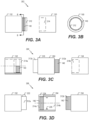
- FIG. 3B illustrates a cross-section view of connector 150 of FIG. 3A taken along cross-section line B-B.
- the mating portion 312 of the connector 152 is illustrated and the LSA 140 is shown on exterior surfaces or walls of connector 152 which define the mating portion 312.
- an adhesive cover film or layer e.g., 294
- connector 150 is made of a light blocking material (e.g., 292), such that when the optional adhesive cover film (e.g., 294) is removed and connection point 302 is formed, light blocking material (e.g., 292) of connector 150 blocks light from reaching LSA 140.
- a light blocking material e.g., 292
- FIG. 3C illustrates a side view of another example of a connection point, connection point 304, having an interconnect 354.
- connection point 304 is formed by joining connectors 152, 154 with interconnect 354.
- Connector 152 is shown in partial cross-section with a bottom half of connector 152 (i.e., below centerline of annular-shaped connector 152) depicting the cross-section of connector 152.
- Interconnect 354 has or defines multiple mating or interface portions 312a and 312b extending from a body 310 (e.g., a connector body) of interconnect 354, each mating or interface portion corresponding to a recess of a tube or connector. As illustrated in FIG.
- interconnect 254 defines a first mating or interface portion 312a corresponding to a first recess 214a of connector 152 and defines a second mating or interface portion 312b corresponding to a second recess 214b of connector 154.
- the first recess 214a includes LSA 140 on a portion of the first recess 214a
- the second mating or interface portion 312b includes LSA 140 on a portion of the second mating or interface portion 312b.
- connection points 302 and 204 may include mechanical alignment features and/or stop features, as described with reference to FIGS. 2C and 2D and illustrated in FIG. 3D .
- FIG. 3D illustrates a side view of another example of a connection point, connection point 306, having an interconnect 354.
- Interconnect 354 is shown in full cross-section for illustrative purposes in FIG. 3D .
- connection point 306 is formed by joining connectors 152, 154 with interconnect 354.
- connectors 152, 154 each have a correspond mating portion 312a, 312b.
- Mating portion 312a is inserted into correspond recess 214a of interconnect 354, and mating portion 312b is inserted into correspond recess 214b of interconnect 354.
- LSA 140 is provided on interconnect 354 in recess 214a and provided on connector 154 on mating portion 312b.
- LSA 140 may be provided on other surfaces of components of connection point 306, as described herein.
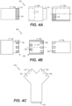
- FIGS. 4A-C illustrate side views of various examples of connection points including elements of FIGS. 2A-2D and 3A-3D .
- FIG. 4C illustrates a top view of an interconnect 454 having multiple inlet or outlet ports.
- FIG. 4A a side view of another example of a connection point 402 is shown.
- connection point 402 includes an interconnect 454, tubes 114a, 114b.
- Tube 114b (or alternatively connector 154) is shown in partial cross-section with a bottom half of tube 114b (i.e., below centerline of annular-shaped tube 114b) depicting the cross-section of tube 114b.
- Interconnect 454 includes both a recess 214 configured to receive a tube or connector and a mating portion 312 portion extending from a base of interconnect 454 which is configured to be inserted into a recess of a tube, a connector, or another component.
- FIG. 4A illustrates one exemplary configuration of LSA 140 for connection point 402 where interconnect 454 does not have LSA 140, i.e., LSA 140 is provided in a 212 of tube 114a (or connector 152) and in a recess of tube 114b.
- recess 214, mating portion 312, or both, of interconnect 454 have LSA 140.
- FIG. 4B illustrates a side view of another example of a connection point including interconnect 454.
- Interconnect 454 is shown in full cross-section for illustrative purposes in FIG. 4B .
- connection point 404 is formed using a pattern 432 of LSA 140 and a two-part LSA 140.
- Two-part LSA 140 includes a first part 440 and a second part 442.
- interconnect 454 defines a recess 214 which is configured to receive connectors 152, 154.
- Connector 152 and interconnect 454 each include a pattern 432 of LSA 140, i.e., one or more portions of LSA 140.
- Connector 154 and interconnect 454 each include portions of parts 440, 442 of two-part LSA 140. As illustrated in FIG. 4B , interconnect 454 includes portions of a first part 440 of two-part LSA 140, and connector 154 includes portions of a second part 440 of two-part LSA 140.
- the pattern 432 and portions of parts 440, 442 may be designed such that they align to form a bond.
- a mechanical guide feature such as pin 222 and slot 224 is used to align the LSA 140, parts 440 and 442 of LSA 140, or elements (e.g., lumens) of the connection point components (e.g., connectors and/or tubes).
- Aligning the LSA 140 includes aligning a pattern 432 of LSA 140, aligning parts 440, 442 of a two-part LSA 140, or both.
- mechanical stop features can be used to control insertion depth to align the LSA 140 and/or parts 440 and 442 of two-part LSA 140. As illustrated in FIG.
- LSA 140 is aligned such that one or more portions of LSA 140 do not overlap, and such that portions of parts 440 and 442 overlap.
- FIG. 4B illustrates a pattern 432 of LSA 140 and a two-part LSA 140
- other implementations described herein may use patterns of LSA 140, two-part LSAs 140, or both. Additionally, or alternatively, the two-part LSA 140 may be used without a pattern.
- first port 412 may have a mating portion 312, and second and third ports 414 and 416 may each have recesses, such as a recess 214.
- LSA 140 may be provided on one or more of interconnect 454, components coupled to interconnect 454, or a combination thereof. As a particular illustrative, non-limiting example, interconnect 454 does not include LSA 140.
- interconnect 254, 354, 454 when an interconnect is used, such as interconnect 254, 354, 454, one or more connections thereof may employ different LSAs 140, such as UV and/or visible light LSAs.
- LSAs 140 such as UV and/or visible light LSAs.
- a particular connection or connections of a connection point may be disconnected, such as inlet side only connections, outlet side only connections, or a portion of connections of a side (inlet or outlet).
- interconnect 454 may have a first type of LSA 140 (e.g., UV LSA) associated with second port 414 and a second type of LSA 440 (e.g., visible light LSA) associated with third port 416.
- the LSA 140 and LSA 440 may be provided on the interconnect 454 or on a component which is coupled to the interconnect 454, such as a tube or a connector described herein.
- a tube connector for system 100 includes a connector body (e.g., 310) configured to define a mating portion (e.g., 212, 312) and LSA 140 coupled to the mating portion of the connector body.
- the mating portion is configured to mate with a corresponding mating portion (e.g., 214) of a tube (e.g., 114, 614, 714).
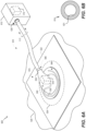
- FIG. 5 illustrates a schematic cross-section view of an example of a dressing of a therapy system, such as dressing 116 of system 100.
- dressing 116 includes LSA 140 for adhesive 502 and defines an optical path to transport light received from connector 130 of dressing 116 to LSA 140 of adhesive 502.
- dressing 116 defines an aperture or cavity 504 or includes a light passing material or medium that is configured to transport and diffuse received light to adhesive 502.
- Cavity 504 (or light passing medium) is configured to pass (e.g., transport and/or diffuse) received light to switch the LSA 140.
- Adhesive 502 may include or correspond to adhesive 137 of FIG. 1 . As illustrated in FIG.
- drape 132 of dressing 116 receives light from tube 114b via an aperture 512 (or light passing medium) in connector 130, and cavity 504 transports the received light to LSA 140 on adhesive 502.
- light reflects off walls of the cavity 504 near the connector 130 and travels to peripheral portions of cavity 504 and dressing 116 where the light diffuses into adhesive 502 to activate LSA 140.
- UV light source e.g., UV device 118
- a container such as therapy device 110 and/or canister 112 of FIG. 1 .
- UV light source such as second light device 518
- the second light device 518 is separate from the canister and/or the therapy system, and the second light device 518 is coupled to a port or window of a connector or a tube to provide the UV light to dressing 116 via tube 114b.
- the second light device 518 may include or correspond to UV device 118, as described herein.
- dressing 116 receives the UV light directly from a UV light source or from ambient light.
- drape 132 of dressing 116 includes a shroud 524.
- the shroud 524 is positioned such that the shroud blocks the LSA 140 from receiving light, such as ambient light.
- the shroud 524 is formed of or includes a material that is configured to block (e.g., reflect or absorb) ambient light that would otherwise activate LSA 140.
- shroud 524 enables the use of ambient light and/or does not require a dedicated light device, transporting light via components of a therapy system, or both. Accordingly, LSA 140 can be activated without a dedicated light device and the connection points can be disconnected without the dedicated light device.
- dressing 116 includes a port or window 522 configured to receive or be coupled with a light source, such as UV device 118.
- a light source such as UV device 118.
- connector 130 or drape 132 includes a port 522 that is optically coupled to or in optical communication with cavity 504.
- the port 522 (or window) includes a removable cover or film that blocks light from entering the cavity 504 and traveling to the LSA 140 of adhesive 502.
- port 522 (or window) may pass or propagate light to cavity 504 to diffuse to the LSA 140 of adhesive 502.
- port or window 522 enables the use of ambient light and/or does not require a dedicated light device, transporting light via components of a therapy system, or both. Accordingly, LSA 140 can be activated without a dedicated light device and the connection points can be disconnected without the dedicated light device.
- dressing 116 includes an internal tube (e.g., fiber optic tube) configured to transport received light to the adhesive, as described further with reference to FIG. 6A .
- the internal tube has a high refractive index along a length of the internal tube and has a relatively lower refractive index at an end of the tube to permit light to escape from the tube.
- a cover film (e.g., 294) is attached to the adhesive 502.
- the cover film may be formed of a thin, clear, flexible, breathable material with a high refractive index.
- One exemplary material for the cover film is polyurethane (PU).
- PU polyurethane
- the cavity 504 or light passing medium in areas where the adhesive 502 abuts the layer (e.g., a diffuser layer), the cavity 504 or light passing medium has a relatively lower refractive index to allow light that reaches the diffuser layer to reflect/refract and be distributed over the diffuser layer.
- the diffuser layer can emit a larger portion of the light in an area of the diffuser layer with a low refractive index.
- a sheath 514 of high refractive material is coupled to at least one tube of the system, such as 114b.
- the sheath 514 is formed with the tube 114b or is coupled to the tube 114b after the system 100 is connected (e.g., during or after operation).
- the sheath 514 is configured to refract light within the tubes 114 and prevent or reduces light within the tubes 114 from escaping the tubes 114.
- sheath 514 refracts light (a portion thereof) that has escaped the tube 114b back into the tube 114b.
- the tube, such as tube 514b, or one or more lumens thereof may include a coating of high refractive material, as described herein.
- At least one tube of the system includes or is made from a low refractive material, such as a material with a refractive index that is less than 1.6.
- low refractive material has a refractive index less than or equal to 1.5.
- Therapy device 610 (e.g., a positive-pressure treatment apparatus) is configured to provide oxygen at a positive-pressure via tube 614 and dressing 616.
- therapy device 610 may include a positive-pressure source, such as a pressurized oxygen container, an oxygen concentrator, or an oxygen collector (e.g., a pump and a filter) and/or the like, configured to be actuatable (and/or actuated) to apply positive-pressure (e.g., hyperbaric pressure) to dressing 616.
- positive-pressure source is included in dressing 616 that includes connector 630, or positive-pressure source is external to dressing 616, included in connector 630, and coupled to dressing 616 via connector 630.
- positive-pressure applied to a tissue site may typically ranges between 5 millimeters mercury (mm Hg) (667 pascals (Pa)) and 30 mm Hg (4.00 kilo (k) Pa). Common therapeutic ranges are between 10 mm Hg (1.33 kPa) and 25 mm Hg (3.33 kPa).
- the therapy device 610 includes a reduced-pressure source, such as a vacuum source (e.g., a pump and/or the like), configured to be actuatable (and/or actuated) to apply reduced-pressure (e.g., negative pressure) to the dressing 616.
- a reduced-pressure source such as a vacuum source (e.g., a pump and/or the like)
- therapy device 610 may alternate between providing positive-pressure therapy and negative-pressure therapy to the dressing 616, may provide positive-pressure therapy to a first portion of the dressing 616 and negative-pressure therapy to a second portion of the dressing 616, may provide no positive or negative pressure, or a combination thereof.
- therapy device 610 includes canister 612 to receive fluid from tissue site 620 or to provide fluid to tissue site 620.
- canister 612 is illustrated as being internal to and/or integrated with therapy device 610, in other implementations, canister 612 is external to therapy device 610, as illustrated and described with reference to FIG. 1 .
- Canister 612 may include or correspond to canister 112 of FIG. 1 .
- tube 614 has been described and/or shown as having a circular cross-sectional shape, in other implementations, tube 614 may have a cross-sectional shape other than a circle, such as an oval, triangle, quadrilateral, pentagon, star, or another shape, as illustrative, non-limiting examples.
- manifold 634 is porous and may be made from foam, gauze, felted mat, or other material suited to a particular biological application.
- manifold 634 may be a porous foam and may include a plurality of interconnected cells or pores that act as flow channels.
- the foam e.g., foam material
- the foam may be either hydrophobic or hydrophilic.
- the porous foam may be a polyurethane, open-cell, reticulated foam such as GranuFoam ® material manufactured by Kinetic Concepts, Incorporated of San Antonio, Tex.
- hydrophilic foam is a polyvinyl alcohol, open-cell foam such as V.A.C. WhiteFoam ® dressing available from Kinetic Concepts, Inc. of San Antonio, Tex.
- Other hydrophilic foams may include those made from polyether and/or foams that have been treated or coated to provide hydrophilicity.
- tube 714 has been described and/or shown as having a circular cross-sectional shape, in other implementations, tube 714 may have a cross-sectional shape other than a circle, such as an oval, triangle, quadrilateral, pentagon, star, or another shape, as illustrative, non-limiting examples.
- primary lumen 721 may be a negative-pressure/fluid lumen
- first secondary lumen 722 may be a positive-pressure/fluid lumen
- secondary lumens 724, 726, 728 may be waveguide or sense lumens.
- connector 730 may operate to maintain fluid communication between interior volume 738 and device 710 via tube 714, and to prevent fluid communication between interior volume (e.g., a sealed therapeutic environment formed by dressing 716) and the ambient environment.
- first port/interface 782, second port/interface 782, third port/interface 784, and fourth port/interface 786 is coupled to one or more components of device 710 via one or more conduits (e.g., 768).
- first port/interface 780 is coupled to positive-pressure source 778
- second port/interface 782 is coupled through fluid chamber 770 (e.g., a canister or a liquid-collection cavity) to negative-pressure source 779
- third port/interface 784 is coupled to a UV device 772
- fourth port/interface 786 is coupled to a pressure sensor 774.
- the pressure sensor 774 may be configured to generate data indicative of pressure within dressing 716.
- Positive-pressure source 778 is configured to provide positive-pressure to interior volume 738 of dressing 716 such that interior volume 738 is expanded, and/or positive-pressure is applied to at least target tissue 736.
- Positive-pressure source 778 may include a mechanically and/or electrically-powered device, such as a manually-actuated or manually-charged pump, an oxygen tank, an oxygen collector, a wall port, a micro-pump, a disc-pump, and/or the like, as illustrative, non-limiting examples.
- the positive-pressure source 778 and the reduced-pressure source 779 may operate in conjunction with each other and are applied to different portions of tissue site 720 via different lumens (e.g., 721, 722) of tube 714.
- the positive-pressure source 778 and the reduced-pressure source 779 share a lumen (e.g., 721 or 722) of tube 714 and the reduced-pressure source 779 operates in the alternative to the positive-pressure source 778 (e.g., operate in distinct cycles).
- the reduced-pressure source 779 operates before or after the positive-pressure source 778 to remove exudate from tissue site 720.
- Processor 790 may include a microcontroller/microprocessor, a central processing unit (CPU), a field-programmable gate array (FPGA) device, an application-specific integrated circuits (ASIC), another hardware device, a firmware device, or any combination thereof.
- Processor 790 may be configured to execute instructions 794, execute and/or operate according to pressure profile 796, and/ process sensor data generate by pressure sensor 774.
- processor 790 may be configured to process sensor data (e.g., pressure signals) received by one or more pressure sensors (e.g., 774) and/or monitor the sensor data.
- processor 790 may be configured to issue one or more alerts according to a predetermined pressure therapy (e.g., pressure profile 796) for a patient and/or based on one or more thresholds 798.
- the one or more alerts may be in the form of a visual alert (e.g., a light indicator), a tactile alert, an audible alert, a message presented via a display, or a message transmitted to another device.
- processor 790 may provide an indication that the sensor data (e.g., the monitored pressure at dressing 716) is following pressure profile 796.
- processor 790 may initiate a visual indication (e.g., a light indicator), a tactile indication, an audible indication, a message presented via a display, or a message transmitted to another device.
- the one or more I/O devices 764 may include a mouse, a keyboard, pointing devices, a display device, the camera, speakers, microphones, touch screens, other I/O devices, or a combination thereof.
- Processor 790 may be configured to send and/or receive data via the interface(s) 762 and/or the I/O device(s) 764.
- dressing 716 is coupled to tissue site 720 so as to cover target tissue 736. Additionally, dressing 716 is coupled to device 710 via tube 714.
- processor 790 receives an input via I/O device 764, such as a touchscreen, to select a pressure profile (e.g., 796) of multiple pressure profiles stored at memory 792, to initiate positive-pressure therapy, or both. Alternatively, the input may indicate a value of a positive-pressure to be provided and/or maintained. Responsive to the input, controller 760 (e.g., processor 790) generates one or more commands to initiate operations of one or more components of device 710.
- processor 790 may access pressure profile 796 (e.g., a set-up profile or a maintenance profile). Additionally, or alternatively, processor 790 may activate and/or regulate positive-pressure source 778, one or more valves 776, or both. In some implementations, processor 790 may control operation of positive-pressure source 778, one or more valves 776 based on at least in part on the input (e.g., the pressure profile 796 selection or the value of the positive-pressure).
- pressure profile 796 e.g., a set-up profile or a maintenance profile.
- processor 790 may activate and/or regulate positive-pressure source 778, one or more valves 776, or both.
- processor 790 may control operation of positive-pressure source 778, one or more valves 776 based on at least in part on the input (e.g., the pressure profile 796 selection or the value of the positive-pressure).
- positive-pressure source 778 may apply positive-pressure to dressing 716.
- positive-pressure developed by positive-pressure source 778 may be delivered through tube 714 to connector 730 of dressing 716. Accordingly, the positive-pressure source 778 can increase a pressure in interior volume 738.
- Internal volume (e.g., a sealed therapeutic environment) and/or target tissue 736 may be isolated from an external environment (associated with an ambient pressure).
- processor 790 is configured to control positive-pressure source 778 (e.g., a positive-pressure source device) and/or one or more valves 776 based at least in part on the sensor data. For example, processor 790 may be configured to deactivate positive-pressure source 778 in response to a determination that the sensor data indicates that a pressure within the interior volume (e.g., 738) is less than a first threshold (e.g., a first threshold pressure value). In some implementations, processor 790 is configured to operate at least one valve (e.g., 776) towards the open position upon or after deactivation of positive-pressure source 778.
- a first threshold e.g., a first threshold pressure value
- the at least one valve may include the valve coupled to positive-pressure source 778, and/or the valve coupled to pressure sensor 774.
- processor 790 may be configured to activate positive-pressure source 778 in response to a determination that the sensor data indicate that a pressure within the interior volume (e.g., 738) is greater than or equal to a second threshold (e.g., a second threshold pressure value). Activation of positive-pressure source 778 may increase pressure within the interior volume (e.g., 738).
- processor 790 is configured to operate at least one valve (e.g., 776) towards the closed position upon or after activation of positive-pressure source 778.
- the first threshold and the second threshold may have the same value. Alternatively, the first threshold and the second threshold may have different values (e.g., the second threshold may be greater than the first threshold).
- Controller 760 may operate valve 776 coupled to pressure sensor 774 based on sensor data received from pressure sensor 774 and/or based on a set of one or more thresholds (e.g., 798). Additionally, or alternatively, in other implementations, controller 760 may operate one or more of the valves based on an average of sensor data of two or more pressure sensors. For example, controller 760 may control one or more valves, such as the valve coupled to positive-pressure source 778 based on an average of the sensor data (received from pressure sensor 774 and another sensor) and the set of one or more thresholds.
- Positive-pressure provided by positive-pressure source 778 via tube 714 can cause pressurized fluid (e.g., oxygen or medication) to be provided to target tissue 736 (e.g., tissue site 720) via tube 714 (e.g., positive-pressure/fluid lumen) and first port/interface 780.
- device 710 may include a sensor and/or regulator (not shown) coupled to controller 760 (e.g. processor 790) and configured to monitor a pressure of the positive-pressure source 778 or the corresponding conduit 768 thereof.
- controller 760 e.g. processor 790
- processor 790 may receive sensor data from the sensor that indicates a pressure level of the regulator and may operate valve 776 to control a pressure and/or volume of positive-pressure source 778. Once a desired pressure of fluid is achieved, the pressurized fluid (e.g., oxygen) may be provided to target tissue 736.
- controller 760 may deactivate device 710 and activate UV device 772. Responsive to activation, UV device 772 emits UV light via conduit 768 to tube 714 via port/interface 748.
- Tube 714 e.g., one or more lumens thereof, such as lumen 724 transports the emitted UV light to connection points of system 700.
- lumen 724 is a dedicated waveguide lumen with high reflectivity and/or includes a sheath or coating to increase reflectively and reduce transmission of UV light through walls of lumen 724 to other lumens and outside tube 714.
- walls of tube 714 reflect UV light to transport the UV light along a length of tube 714.
- An illustrative light propagation path 773 is depicted in FIG. 7 to illustrate one example path of the UV light emitted from UV device 772 propagating through conduit 768, port/interface 748, tubes 714 (e.g., reflecting off walls thereof), and connector 730 to dressing 716, where the UV light can be transported or dispersed to adhesive 737 by dressing 716, as described with reference to FIGS. 1 , 5 , and 6A .
- controller 760 activates and/or controls UV device 772 responsive to receiving a wireless communication via interface(s) 762 (e.g., a wireless interface).
- a remote control or mobile device transmits a code or password (i.e., data indicating a code or password) to controller 760.
- Processor 790 determines whether a received code or password matches a code or password stored in memory 792. Responsive to determining a match and authenticating the code or password, controller 760 sends an activation signal to UV device 772 to cause UV device 772 to emit light.
- controller 760 may open and close valves in one or more conduits 768 to allow or block one or more lumens corresponding to the one or more conduits 768 from receiving light.
- controller 760 sends control signals to UV device 772, and UV device 772 activates one or more LEDs thereof associated with lumens corresponding to the selected connection point or points.
- UV device 772 provides UV light a first lumen of tube 714 which has a transmission element at an in-line connector connection point, such as connection point 162, and UV device 772 does not provide light to other lumens of tube 714 which have transmission elements at or near other connection points of system 700.
- FIG. 7A describes system 700 for controlling the application of light to connection points of system 700 to activate LSA.
- System 700 may advantageously include UV device 772 configured to generate UV light and one or more components to transport the UV light to LSA of connection points of system 700 to activate the LSA. For example, applying UV light to the LSA transitions the LSA from the high tack state to the low tack state to enable disconnection of the connection points.
- system 700 provides secure single-use connections and hinders or prevents reuse of single- use components to reduce infection and contamination.
- system 700 provides easy assembly and disconnection with a low disconnection force enabling the young, elderly, and sick to easily connect and disconnect components of system 700.
- system 700 may advantageously include light guide, cover films, port/windows or other components described herein to further enable protection of LSA and selective activation of connection points.
- FIG. 8 illustrates a method 800 of disconnecting a connection point of a therapy system.
- the method 800 may be performed at, by, or with system 100 (e.g., one or more components thereof), a system that includes one or more of a connector (130, 150, 152, 154, 254, 354, 454, 630, 638, 730), a tube (e.g., 114, 614, 714), or a light source (e.g., UV device 118, 518), the system 600 (e.g., one or more components thereof), or the system 700 (e.g., one or more components thereof).
- system 100 e.g., one or more components thereof
- the system 600 e
- Method 800 includes emitting UV light by a UV Device, at 810.
- the UV Device may include or correspond to UV Device 118, second light device 518, or UV Device 772.
- the light switchable adhesive may include or correspond to LSA 140, two-part LSA 140 (e.g., part 440, part 440), second type LSA 440, or a combination thereof.
- the connection point may include or correspond to one of connection points 162-168, 202-206, 302-306, 402, 404, one of the connection points of FIG. 5 , one of the connection points of FIG. 6A , or one of the connection points of FIG. 7A .
- method 800 describes operation of disconnecting a connection point of a therapy system by applying light to a light switchable adhesive of the connection point. Therefore, a patient or care provider can easily disconnect the components and is hindered or restricted from reusing the components which form the connection point. Accordingly, the single-use components may enable sterile, efficient, and safe use of the therapy system.
Landscapes
- Health & Medical Sciences (AREA)
- Heart & Thoracic Surgery (AREA)
- Hematology (AREA)
- Veterinary Medicine (AREA)
- Engineering & Computer Science (AREA)
- Anesthesiology (AREA)
- Biomedical Technology (AREA)
- Life Sciences & Earth Sciences (AREA)
- Animal Behavior & Ethology (AREA)
- General Health & Medical Sciences (AREA)
- Public Health (AREA)
- Vascular Medicine (AREA)
- Pulmonology (AREA)
- Organic Chemistry (AREA)
- Chemical & Material Sciences (AREA)
- Dermatology (AREA)
- Radiation-Therapy Devices (AREA)
- Media Introduction/Drainage Providing Device (AREA)
- External Artificial Organs (AREA)
Claims (14)
- Ein Therapiesystem (100), umfassend:einen Verbindungspunkt (160, 162, 164), der einen Verbinder aufweist, der einen ersten durch Licht veränderbaren Klebstoff (142, 502) aufweist, der an einem Anschlussabschnitt des Verbinders bereitgestellt ist; undeine UV-Vorrichtung (118), die konfiguriert ist, um ein erstes Licht an den ersten durch Licht veränderbaren Klebstoff über eine oder mehrere Komponenten des Therapiesystems abzugeben, und wobei der durch Licht veränderbare Klebstoff konfiguriert ist, um Zustände, basierend auf dem ersten Licht, zu verändern, dadurch gekennzeichnet, dassdas Therapiesystem ferner einen zweiten durch Licht veränderbaren Klebstoff (142, 502) umfasst, wobei der zweite durch Licht veränderbare Klebstoff konfiguriert ist, um Zustände, basierend auf zweitem Licht (518), zu verändern, wobei das zweite Licht einem unterschiedlichen Spektrum als das erste Licht entspricht.
- Das Therapiesystem nach Anspruch 1, wobei der Verbindungspunkt einen Verbindungspunkt zwischen einer Therapievorrichtung (110) und einem Kanister (112), zwischen dem Kanister (112) und einem Satz von Schläuchen (114), innerhalb des Satzes von Schläuchen (114), zwischen dem Satz von Schläuchen und einem Verband (116) oder zwischen dem Verband (116) und einem Patienten (120) umfasst.
- Das Therapiesystem nach Anspruch 1, ferner umfassend eine Therapievorrichtung (110) und einen Verband (116) in Fluidverbindung mit der Therapievorrichtung.
- Das Therapiesystem nach Anspruch 3, der Verband ferner umfassend einen Lichtleiter (504, 604), der konfiguriert ist, um Licht, das durch den Verband empfangen wird, zu einem Klebstoff, der mit dem Verband gekoppelt ist, zu transportieren.
- Das Therapiesystem nach Anspruch 4, ferner umfassend einen Kanister (112), der mit der Therapievorrichtung (110) gekoppelt und konfiguriert ist, um Fluid aus dem Verband aufzunehmen.
- Das Therapiesystem nach Anspruch 4, wobei:die Therapievorrichtung (110) konfiguriert ist, um Überdruck, reduzierten Druck oder beides auf den Verband (116) auszuüben; unddie UV-Einrichtung (118) in die Therapievorrichtung oder den Verband integriert ist.
- Das Therapiesystem nach Anspruch 6, wobei die Therapievorrichtung eine Steuerung (760) umfasst, die konfiguriert ist, um den Betrieb der Therapievorrichtung, der UV-Vorrichtung oder beider zu steuern.
- Ein Verfahren, umfassend:Emittieren von UV-Licht durch eine UV-Vorrichtung (118);Übertragen, durch eine oder mehrere Komponenten eines Therapiesystems (100), des UV-Lichts an einen ersten durch Licht veränderbaren Klebstoff (142, 502) eines Verbindungspunkts des Therapiesystems; undals Reaktion auf das UV-Licht, das dem durch Licht veränderbaren Klebstoff bereitgestellt wird, Übergehen, von einem ersten Zustand in einen zweiten Zustand, des ersten durch Licht veränderbaren Klebstoffs, gekennzeichnet durchÜbertragen eines zweiten Lichts auf einen zweiten durch Licht veränderbaren Klebstoff (142, 502), wobei der zweite durch Licht veränderbare Klebstoff konfiguriert ist, um Zustände, basierend auf dem zweiten Licht, zu verändern, und wobei das zweite Licht einem unterschiedlichen Spektrum als das erste Licht entspricht.
- Das Verfahren nach Anspruch 8, ferner umfassend ein Trennen des Verbindungspunkts (160, 162, 164), wobei der zweite Zustand eine geringere Abziehfestigkeit als der erste Zustand aufweist.
- Das Verfahren nach Anspruch 8, ferner umfassend als Reaktion auf das UV-Licht, eine Farbänderung des durch Licht veränderbaren Klebstoffs.
- Das Verfahren nach Anspruch 8, ferner umfassend vor dem Bereitstellen des UV-Lichts, das Verbinden einer Therapievorrichtung (110), eines Kanisters (112), eines Schlauchs (114), eines Verbinders (130, 150, 152, 154, 630, 638) oder eines Verbands (116, 616) mit einem anderen der Therapievorrichtung (110), des Kanisters (112), des Schlauchs (114), des Verbinders (130, 150, 152, 154, 630, 638) oder des Verbands (116, 616), um den Verbindungspunkt (160, 162, 164) auszubilden.
- Das Verfahren nach Anspruch 8, ferner umfassend das Bereitstellen des UV-Lichts an einen zweiten durch Licht veränderbaren Klebstoff eines zweiten Verbindungspunkts des Therapiesystems.
- Das Verfahren nach Anspruch 8, ferner umfassend ein Empfangen eines Codes an einer Steuerung (760), die der UV-Vorrichtung (118) zugeordnet ist, wobei die UV-Vorrichtung das UV-Licht als Reaktion auf das Empfangen des Codes emittiert.
- Verfahren nach Anspruch 8, ferner umfassend ein Einstellen eines Zeitgebers, der der UV-Vorrichtung zugeordnet ist, wobei die UV-Vorrichtung das UV-Licht als Reaktion auf den Ablauf des Zeitgebers emittiert.
Applications Claiming Priority (2)
| Application Number | Priority Date | Filing Date | Title |
|---|---|---|---|
| US201962790196P | 2019-01-09 | 2019-01-09 | |
| PCT/US2020/012467 WO2020146306A1 (en) | 2019-01-09 | 2020-01-07 | Apparatus, system, and method for therapy system components employing light switchable adhesives |
Publications (2)
| Publication Number | Publication Date |
|---|---|
| EP3908347A1 EP3908347A1 (de) | 2021-11-17 |
| EP3908347B1 true EP3908347B1 (de) | 2024-07-03 |
Family
ID=69467723
Family Applications (1)
| Application Number | Title | Priority Date | Filing Date |
|---|---|---|---|
| EP20703596.5A Active EP3908347B1 (de) | 2019-01-09 | 2020-01-07 | Vorrichtung, system und verfahren für therapiesystemkomponenten unter verwendung von lichtschaltbaren klebstoffen |
Country Status (3)
| Country | Link |
|---|---|
| US (1) | US12268835B2 (de) |
| EP (1) | EP3908347B1 (de) |
| WO (1) | WO2020146306A1 (de) |
Families Citing this family (8)
| Publication number | Priority date | Publication date | Assignee | Title |
|---|---|---|---|---|
| DK1762259T3 (da) | 2005-09-12 | 2011-01-03 | Unomedical As | Indføringsindretning til infusionssæt med en første og en anden fjederenhed |
| WO2012123274A1 (en) | 2011-03-14 | 2012-09-20 | Unomedical A/S | Inserter system with transport protection |
| US20210383403A1 (en) * | 2014-01-15 | 2021-12-09 | Federal Law Enforcement Development Services, Inc. | UV, SOUND POINT, iA OPERATING SYSTEM |
| AU2020208843A1 (en) | 2019-01-17 | 2021-08-05 | Moleculight Inc. | Modular system for multi-modal imaging and analysis |
| CA3127048A1 (en) * | 2019-01-17 | 2020-07-23 | Sbi Alapharma Canada, Inc. | Devices, systems, and methods for tumor visualization and removal |
| EP3972672A4 (de) | 2019-05-20 | 2023-06-21 | Unomedical A/S | Drehbare infusionsvorrichtung und verfahren dafür |
| WO2022223646A1 (en) * | 2021-04-21 | 2022-10-27 | T.J. Smith And Nephew, Limited | Communication systems and methods for negative pressure wound therapy devices |
| EP4554540A1 (de) * | 2022-07-14 | 2025-05-21 | Solventum Intellectual Properties Company | Umschaltbarer verband für unterdrucktherapie |
Citations (1)
| Publication number | Priority date | Publication date | Assignee | Title |
|---|---|---|---|---|
| WO2019139806A1 (en) * | 2018-01-09 | 2019-07-18 | Kci Licensing, Inc. | Systems and methods for coupling a wearable therapy system to a dressing |
Family Cites Families (134)
| Publication number | Priority date | Publication date | Assignee | Title |
|---|---|---|---|---|
| US1355846A (en) | 1920-02-06 | 1920-10-19 | David A Rannells | Medical appliance |
| US2547758A (en) | 1949-01-05 | 1951-04-03 | Wilmer B Keeling | Instrument for treating the male urethra |
| US2632443A (en) | 1949-04-18 | 1953-03-24 | Eleanor P Lesher | Surgical dressing |
| GB692578A (en) | 1949-09-13 | 1953-06-10 | Minnesota Mining & Mfg | Improvements in or relating to drape sheets for surgical use |
| US2682873A (en) | 1952-07-30 | 1954-07-06 | Johnson & Johnson | General purpose protective dressing |
| NL189176B (nl) | 1956-07-13 | 1900-01-01 | Hisamitsu Pharmaceutical Co | Pleister op basis van een synthetische rubber. |
| US2969057A (en) | 1957-11-04 | 1961-01-24 | Brady Co W H | Nematodic swab |
| US3066672A (en) | 1960-09-27 | 1962-12-04 | Jr William H Crosby | Method and apparatus for serial sampling of intestinal juice |
| US3367332A (en) | 1965-08-27 | 1968-02-06 | Gen Electric | Product and process for establishing a sterile area of skin |
| US3520300A (en) | 1967-03-15 | 1970-07-14 | Amp Inc | Surgical sponge and suction device |
| US3568675A (en) | 1968-08-30 | 1971-03-09 | Clyde B Harvey | Fistula and penetrating wound dressing |
| US3682180A (en) | 1970-06-08 | 1972-08-08 | Coilform Co Inc | Drain clip for surgical drain |
| BE789293Q (fr) | 1970-12-07 | 1973-01-15 | Parke Davis & Co | Pansement medico-chirugical pour brulures et lesions analogues |
| US3826254A (en) | 1973-02-26 | 1974-07-30 | Verco Ind | Needle or catheter retaining appliance |
| DE2527706A1 (de) | 1975-06-21 | 1976-12-30 | Hanfried Dr Med Weigand | Einrichtung zum einleiten von kontrastmittel in einen kuenstlichen darmausgang |
| DE2640413C3 (de) | 1976-09-08 | 1980-03-27 | Richard Wolf Gmbh, 7134 Knittlingen | Katheter-Überwachungsgerät |
| NL7710909A (nl) | 1976-10-08 | 1978-04-11 | Smith & Nephew | Samengestelde hechtstrook. |
| GB1562244A (en) | 1976-11-11 | 1980-03-05 | Lock P M | Wound dressing materials |
| US4080970A (en) | 1976-11-17 | 1978-03-28 | Miller Thomas J | Post-operative combination dressing and internal drain tube with external shield and tube connector |
| US4139004A (en) | 1977-02-17 | 1979-02-13 | Gonzalez Jr Harry | Bandage apparatus for treating burns |
| US4184510A (en) | 1977-03-15 | 1980-01-22 | Fibra-Sonics, Inc. | Valued device for controlling vacuum in surgery |
| US4165748A (en) | 1977-11-07 | 1979-08-28 | Johnson Melissa C | Catheter tube holder |
| US4245637A (en) | 1978-07-10 | 1981-01-20 | Nichols Robert L | Shutoff valve sleeve |
| SE414994B (sv) | 1978-11-28 | 1980-09-01 | Landstingens Inkopscentral | Venkateterforband |
| GB2047543B (en) | 1978-12-06 | 1983-04-20 | Svedman Paul | Device for treating tissues for example skin |
| US4266545A (en) | 1979-04-06 | 1981-05-12 | Moss James P | Portable suction device for collecting fluids from a closed wound |
| US4284079A (en) | 1979-06-28 | 1981-08-18 | Adair Edwin Lloyd | Method for applying a male incontinence device |
| US4261363A (en) | 1979-11-09 | 1981-04-14 | C. R. Bard, Inc. | Retention clips for body fluid drains |
| US4569348A (en) | 1980-02-22 | 1986-02-11 | Velcro Usa Inc. | Catheter tube holder strap |
| ATE14835T1 (de) | 1980-03-11 | 1985-08-15 | Schmid Eduard | Hauttransplantations-druckverband. |
| US4297995A (en) | 1980-06-03 | 1981-11-03 | Key Pharmaceuticals, Inc. | Bandage containing attachment post |
| US4333468A (en) | 1980-08-18 | 1982-06-08 | Geist Robert W | Mesentery tube holder apparatus |
| US4465485A (en) | 1981-03-06 | 1984-08-14 | Becton, Dickinson And Company | Suction canister with unitary shut-off valve and filter features |
| US4392853A (en) | 1981-03-16 | 1983-07-12 | Rudolph Muto | Sterile assembly for protecting and fastening an indwelling device |
| US4373519A (en) | 1981-06-26 | 1983-02-15 | Minnesota Mining And Manufacturing Company | Composite wound dressing |
| US4392858A (en) | 1981-07-16 | 1983-07-12 | Sherwood Medical Company | Wound drainage device |
| US4419097A (en) | 1981-07-31 | 1983-12-06 | Rexar Industries, Inc. | Attachment for catheter tube |
| SE429197B (sv) | 1981-10-14 | 1983-08-22 | Frese Nielsen | Anordning for behandling av sar |
| DE3146266A1 (de) | 1981-11-21 | 1983-06-01 | B. Braun Melsungen Ag, 3508 Melsungen | Kombinierte vorrichtung fuer eine medizinische saugdrainage |
| US4551139A (en) | 1982-02-08 | 1985-11-05 | Marion Laboratories, Inc. | Method and apparatus for burn wound treatment |
| US4475909A (en) | 1982-05-06 | 1984-10-09 | Eisenberg Melvin I | Male urinary device and method for applying the device |
| EP0100148B1 (de) | 1982-07-06 | 1986-01-08 | Dow Corning Limited | Medizinischer chirurgischer Wundverband und Verfahren zu seiner Herstellung |
| NZ206837A (en) | 1983-01-27 | 1986-08-08 | Johnson & Johnson Prod Inc | Thin film adhesive dressing:backing material in three sections |
| US4548202A (en) | 1983-06-20 | 1985-10-22 | Ethicon, Inc. | Mesh tissue fasteners |
| US4540412A (en) | 1983-07-14 | 1985-09-10 | The Kendall Company | Device for moist heat therapy |
| US4543100A (en) | 1983-11-01 | 1985-09-24 | Brodsky Stuart A | Catheter and drain tube retainer |
| US4525374A (en) | 1984-02-27 | 1985-06-25 | Manresa, Inc. | Treating hydrophobic filters to render them hydrophilic |
| CA1286177C (en) | 1984-05-03 | 1991-07-16 | Smith And Nephew Associated Companies Plc | Adhesive wound dressing |
| US4897081A (en) | 1984-05-25 | 1990-01-30 | Thermedics Inc. | Percutaneous access device |
| US5215522A (en) | 1984-07-23 | 1993-06-01 | Ballard Medical Products | Single use medical aspirating device and method |
| GB8419745D0 (en) | 1984-08-02 | 1984-09-05 | Smith & Nephew Ass | Wound dressing |
| US4872450A (en) | 1984-08-17 | 1989-10-10 | Austad Eric D | Wound dressing and method of forming same |
| US4826494A (en) | 1984-11-09 | 1989-05-02 | Stryker Corporation | Vacuum wound drainage system |
| US4655754A (en) | 1984-11-09 | 1987-04-07 | Stryker Corporation | Vacuum wound drainage system and lipids baffle therefor |
| US4605399A (en) | 1984-12-04 | 1986-08-12 | Complex, Inc. | Transdermal infusion device |
| US5037397A (en) | 1985-05-03 | 1991-08-06 | Medical Distributors, Inc. | Universal clamp |
| US4640688A (en) | 1985-08-23 | 1987-02-03 | Mentor Corporation | Urine collection catheter |
| US4710165A (en) | 1985-09-16 | 1987-12-01 | Mcneil Charles B | Wearable, variable rate suction/collection device |
| US4758220A (en) | 1985-09-26 | 1988-07-19 | Alcon Laboratories, Inc. | Surgical cassette proximity sensing and latching apparatus |
| US4733659A (en) | 1986-01-17 | 1988-03-29 | Seton Company | Foam bandage |
| EP0256060A1 (de) | 1986-01-31 | 1988-02-24 | OSMOND, Roger L. W. | Absaugungssystem für wund-, magen- und darmdrainage |
| US4838883A (en) | 1986-03-07 | 1989-06-13 | Nissho Corporation | Urine-collecting device |
| JPS62281965A (ja) | 1986-05-29 | 1987-12-07 | テルモ株式会社 | カテ−テルおよびカテ−テル用固定部材 |
| GB8621884D0 (en) | 1986-09-11 | 1986-10-15 | Bard Ltd | Catheter applicator |
| GB2195255B (en) | 1986-09-30 | 1991-05-01 | Vacutec Uk Limited | Apparatus for vacuum treatment of an epidermal surface |
| US4743232A (en) | 1986-10-06 | 1988-05-10 | The Clinipad Corporation | Package assembly for plastic film bandage |
| DE3634569A1 (de) | 1986-10-10 | 1988-04-21 | Sachse Hans E | Kondomkatheter, ein harnroehrenkatheter zur verhinderung von aufsteigenden infektionen |
| JPS63135179A (ja) | 1986-11-26 | 1988-06-07 | 立花 俊郎 | 薬物の経皮投与具 |
| GB8628564D0 (en) | 1986-11-28 | 1987-01-07 | Smiths Industries Plc | Anti-foaming agent suction apparatus |
| GB8706116D0 (en) | 1987-03-14 | 1987-04-15 | Smith & Nephew Ass | Adhesive dressings |
| US4787888A (en) | 1987-06-01 | 1988-11-29 | University Of Connecticut | Disposable piezoelectric polymer bandage for percutaneous delivery of drugs and method for such percutaneous delivery (a) |
| US4863449A (en) | 1987-07-06 | 1989-09-05 | Hollister Incorporated | Adhesive-lined elastic condom cathether |
| US5176663A (en) | 1987-12-02 | 1993-01-05 | Pal Svedman | Dressing having pad with compressibility limiting elements |
| US4906240A (en) | 1988-02-01 | 1990-03-06 | Matrix Medica, Inc. | Adhesive-faced porous absorbent sheet and method of making same |
| US4985019A (en) | 1988-03-11 | 1991-01-15 | Michelson Gary K | X-ray marker |
| GB8812803D0 (en) | 1988-05-28 | 1988-06-29 | Smiths Industries Plc | Medico-surgical containers |
| US4919654A (en) | 1988-08-03 | 1990-04-24 | Kalt Medical Corporation | IV clamp with membrane |
| US5000741A (en) | 1988-08-22 | 1991-03-19 | Kalt Medical Corporation | Transparent tracheostomy tube dressing |
| US5059596A (en) | 1989-01-16 | 1991-10-22 | Roussel Uclaf | Azabicyclo compounds |
| GB8906100D0 (en) | 1989-03-16 | 1989-04-26 | Smith & Nephew | Laminates |
| US5261893A (en) | 1989-04-03 | 1993-11-16 | Zamierowski David S | Fastening system and method |
| US5100396A (en) | 1989-04-03 | 1992-03-31 | Zamierowski David S | Fluidic connection system and method |
| US4969880A (en) | 1989-04-03 | 1990-11-13 | Zamierowski David S | Wound dressing and treatment method |
| US5527293A (en) | 1989-04-03 | 1996-06-18 | Kinetic Concepts, Inc. | Fastening system and method |
| JP2719671B2 (ja) | 1989-07-11 | 1998-02-25 | 日本ゼオン株式会社 | 創傷被覆材 |
| US5358494A (en) | 1989-07-11 | 1994-10-25 | Svedman Paul | Irrigation dressing |
| US5232453A (en) | 1989-07-14 | 1993-08-03 | E. R. Squibb & Sons, Inc. | Catheter holder |
| GB2235877A (en) | 1989-09-18 | 1991-03-20 | Antonio Talluri | Closed wound suction apparatus |
| US5134994A (en) | 1990-02-12 | 1992-08-04 | Say Sam L | Field aspirator in a soft pack with externally mounted container |
| US5092858A (en) | 1990-03-20 | 1992-03-03 | Becton, Dickinson And Company | Liquid gelling agent distributor device |
| AU650575B2 (en) | 1990-09-25 | 1994-06-23 | Morrison-Knudsen Company, Inc. | Transit car door system and operation |
| US5149331A (en) | 1991-05-03 | 1992-09-22 | Ariel Ferdman | Method and device for wound closure |
| US5278100A (en) | 1991-11-08 | 1994-01-11 | Micron Technology, Inc. | Chemical vapor deposition technique for depositing titanium silicide on semiconductor wafers |
| US5645081A (en) | 1991-11-14 | 1997-07-08 | Wake Forest University | Method of treating tissue damage and apparatus for same |
| US5636643A (en) | 1991-11-14 | 1997-06-10 | Wake Forest University | Wound treatment employing reduced pressure |
| US5279550A (en) | 1991-12-19 | 1994-01-18 | Gish Biomedical, Inc. | Orthopedic autotransfusion system |
| US5167613A (en) | 1992-03-23 | 1992-12-01 | The Kendall Company | Composite vented wound dressing |
| FR2690617B1 (fr) | 1992-04-29 | 1994-06-24 | Cbh Textile | Pansement adhesif transparent. |
| DE4306478A1 (de) | 1993-03-02 | 1994-09-08 | Wolfgang Dr Wagner | Drainagevorrichtung, insbesondere Pleuradrainagevorrichtung, und Drainageverfahren |
| US5342376A (en) | 1993-05-03 | 1994-08-30 | Dermagraphics, Inc. | Inserting device for a barbed tissue connector |
| US6241747B1 (en) | 1993-05-03 | 2001-06-05 | Quill Medical, Inc. | Barbed Bodily tissue connector |
| US5344415A (en) | 1993-06-15 | 1994-09-06 | Deroyal Industries, Inc. | Sterile system for dressing vascular access site |
| US5437651A (en) | 1993-09-01 | 1995-08-01 | Research Medical, Inc. | Medical suction apparatus |
| US5549584A (en) | 1994-02-14 | 1996-08-27 | The Kendall Company | Apparatus for removing fluid from a wound |
| US5607388A (en) | 1994-06-16 | 1997-03-04 | Hercules Incorporated | Multi-purpose wound dressing |
| US5556375A (en) | 1994-06-16 | 1996-09-17 | Hercules Incorporated | Wound dressing having a fenestrated base layer |
| US5664270A (en) | 1994-07-19 | 1997-09-09 | Kinetic Concepts, Inc. | Patient interface system |
| ATE172377T1 (de) | 1994-08-22 | 1998-11-15 | Kinetic Concepts Inc | Wunddrainagevorrichtung |
| DE29504378U1 (de) | 1995-03-15 | 1995-09-14 | MTG Medizinisch, technische Gerätebau GmbH, 66299 Friedrichsthal | Elektronisch geregelte Niedervakuumpumpe für die Thorax- und Wunddrainage |
| GB9523253D0 (en) | 1995-11-14 | 1996-01-17 | Mediscus Prod Ltd | Portable wound treatment apparatus |
| US6135116A (en) | 1997-07-28 | 2000-10-24 | Kci Licensing, Inc. | Therapeutic method for treating ulcers |
| AU755496B2 (en) | 1997-09-12 | 2002-12-12 | Kci Licensing, Inc. | Surgical drape and suction head for wound treatment |
| GB9719520D0 (en) | 1997-09-12 | 1997-11-19 | Kci Medical Ltd | Surgical drape and suction heads for wound treatment |
| GB9720922D0 (en) * | 1997-10-02 | 1997-12-03 | Smith & Nephew | Adhesives |
| US6071267A (en) | 1998-02-06 | 2000-06-06 | Kinetic Concepts, Inc. | Medical patient fluid management interface system and method |
| US6488643B1 (en) | 1998-10-08 | 2002-12-03 | Kci Licensing, Inc. | Wound healing foot wrap |
| US6287316B1 (en) | 1999-03-26 | 2001-09-11 | Ethicon, Inc. | Knitted surgical mesh |
| US7799004B2 (en) | 2001-03-05 | 2010-09-21 | Kci Licensing, Inc. | Negative pressure wound treatment apparatus and infection identification system and method |
| US6856821B2 (en) | 2000-05-26 | 2005-02-15 | Kci Licensing, Inc. | System for combined transcutaneous blood gas monitoring and vacuum assisted wound closure |
| GB9908000D0 (en) * | 1999-04-09 | 1999-06-02 | Smith & Nephew | Curable compositions |
| US6991643B2 (en) | 2000-12-20 | 2006-01-31 | Usgi Medical Inc. | Multi-barbed device for retaining tissue in apposition and methods of use |
| GB9926538D0 (en) * | 1999-11-09 | 2000-01-12 | Kci Medical Ltd | Multi-lumen connector |
| EP1257313B1 (de) | 2000-02-24 | 2004-05-12 | Venetec International, Inc. | Universelles katheterbefestigungssystem |
| JP2001240842A (ja) * | 2000-02-28 | 2001-09-04 | Nitto Denko Corp | 紫外線硬化型粘着剤組成物とその粘着シ―ト類 |
| US6540705B2 (en) | 2001-02-22 | 2003-04-01 | Core Products International, Inc. | Ankle brace providing upper and lower ankle adjustment |
| GB0325126D0 (en) * | 2003-10-28 | 2003-12-03 | Smith & Nephew | Apparatus with heat |
| US20060225832A1 (en) * | 2005-03-30 | 2006-10-12 | Saidman Laurence B | Method for dispensing an energy reactive adhesive |
| US20120302844A1 (en) * | 2010-01-14 | 2012-11-29 | Schnidrig Juerg | Skin mounted medical patch device |
| EP2371920A1 (de) | 2010-03-31 | 2011-10-05 | Lumina Adhesives AB | Umschaltbare Klebstoffe |
| US10076449B2 (en) * | 2012-08-01 | 2018-09-18 | Smith & Nephew Plc | Wound dressing and method of treatment |
| EP3669842B1 (de) * | 2012-11-16 | 2023-09-27 | 3M Innovative Properties Company | Medizinisches tuch mit musterkleberschichten |
| GB201404021D0 (en) * | 2014-03-05 | 2014-04-23 | Lumina Adhesives Ab | Low cytotoxity switchable adhesive compositions, medical dressings and skin coverings, and methods of treatment using same |
| CA3023772A1 (en) * | 2016-05-13 | 2017-11-16 | Smith & Nephew Plc | Sensor enabled wound monitoring and therapy apparatus |
| WO2019083869A1 (en) * | 2017-10-23 | 2019-05-02 | Kci Licensing, Inc. | SYSTEMS AND METHODS FOR HIGH RESISTANCE CARTRIDGE RETENTION WITH AUTOMATED NON-MECHANICAL CARTRIDGE RELEASE FOR USE WITH MEDICAL FLUID COLLECTION SYSTEMS |
-
2020
- 2020-01-07 EP EP20703596.5A patent/EP3908347B1/de active Active
- 2020-01-07 US US17/419,098 patent/US12268835B2/en active Active
- 2020-01-07 WO PCT/US2020/012467 patent/WO2020146306A1/en not_active Ceased
Patent Citations (1)
| Publication number | Priority date | Publication date | Assignee | Title |
|---|---|---|---|---|
| WO2019139806A1 (en) * | 2018-01-09 | 2019-07-18 | Kci Licensing, Inc. | Systems and methods for coupling a wearable therapy system to a dressing |
Also Published As
| Publication number | Publication date |
|---|---|
| US20220072294A1 (en) | 2022-03-10 |
| WO2020146306A1 (en) | 2020-07-16 |
| EP3908347A1 (de) | 2021-11-17 |
| US12268835B2 (en) | 2025-04-08 |
Similar Documents
| Publication | Publication Date | Title |
|---|---|---|
| EP3908347B1 (de) | Vorrichtung, system und verfahren für therapiesystemkomponenten unter verwendung von lichtschaltbaren klebstoffen | |
| EP3260144B1 (de) | Systeme zur entnahme von exsudaten in der druckreduzierten therapie | |
| AU2013237989B2 (en) | Reduced-pressure systems, dressings, and methods facilitating separation of electronic and clinical component parts | |
| US20220176606A1 (en) | Apparatus, system, and method for forming a compound film, and apparatus having a compound film | |
| EP3384955B1 (de) | Lecksichere bandagensysteme und mit hydrophilem schaumstoffwundeinsatz für flüssigkeitsstillungs- und/oder unterdruckwundtherapien | |
| US20220167987A1 (en) | Apparatus, system, and method for wound closure | |
| EP3419686B1 (de) | Handbetätigtes unterdrucktherapiesystem mit integriertem hörbarem feedback | |
| US12458539B2 (en) | Drapes with regions with higher adhesive properties | |
| US20200385614A1 (en) | Dual electromagnetic radiation light switchable adhesive and apparatuses, systems, and methods therefore | |
| EP4048214B1 (de) | Zweiteiliger verband mit wechselbarem klebstoff | |
| US20220016331A1 (en) | Apparatus, system, and method for mechanical indication of pressure | |
| US12496230B2 (en) | Moisture and electromagnetic radiation switchable adhesive and apparatuses, systems, and methods therefore | |
| US20220387224A1 (en) | Oxygenated hemoglobin and apparatuses, systems, and methods therefore | |
| WO2020072493A1 (en) | Apparatus, system, and method for a connector of a dressing of a reduced-pressure system |
Legal Events
| Date | Code | Title | Description |
|---|---|---|---|
| STAA | Information on the status of an ep patent application or granted ep patent |
Free format text: STATUS: UNKNOWN |
|
| STAA | Information on the status of an ep patent application or granted ep patent |
Free format text: STATUS: THE INTERNATIONAL PUBLICATION HAS BEEN MADE |
|
| PUAI | Public reference made under article 153(3) epc to a published international application that has entered the european phase |
Free format text: ORIGINAL CODE: 0009012 |
|
| STAA | Information on the status of an ep patent application or granted ep patent |
Free format text: STATUS: REQUEST FOR EXAMINATION WAS MADE |
|
| 17P | Request for examination filed |
Effective date: 20210721 |
|
| AK | Designated contracting states |
Kind code of ref document: A1 Designated state(s): AL AT BE BG CH CY CZ DE DK EE ES FI FR GB GR HR HU IE IS IT LI LT LU LV MC MK MT NL NO PL PT RO RS SE SI SK SM TR |
|
| DAV | Request for validation of the european patent (deleted) | ||
| DAX | Request for extension of the european patent (deleted) | ||
| RAP1 | Party data changed (applicant data changed or rights of an application transferred) |
Owner name: 3M INNOVATIVE PROPERTIES COMPANY |
|
| RAP1 | Party data changed (applicant data changed or rights of an application transferred) |
Owner name: SOLVENTUM INTELLECTUAL PROPERTIES COMPANY |
|
| GRAP | Despatch of communication of intention to grant a patent |
Free format text: ORIGINAL CODE: EPIDOSNIGR1 |
|
| STAA | Information on the status of an ep patent application or granted ep patent |
Free format text: STATUS: GRANT OF PATENT IS INTENDED |
|
| INTG | Intention to grant announced |
Effective date: 20240419 |
|
| GRAS | Grant fee paid |
Free format text: ORIGINAL CODE: EPIDOSNIGR3 |
|
| GRAA | (expected) grant |
Free format text: ORIGINAL CODE: 0009210 |
|
| STAA | Information on the status of an ep patent application or granted ep patent |
Free format text: STATUS: THE PATENT HAS BEEN GRANTED |
|
| AK | Designated contracting states |
Kind code of ref document: B1 Designated state(s): AL AT BE BG CH CY CZ DE DK EE ES FI FR GB GR HR HU IE IS IT LI LT LU LV MC MK MT NL NO PL PT RO RS SE SI SK SM TR |
|
| RIN1 | Information on inventor provided before grant (corrected) |
Inventor name: ROBINSON, TIMOTHY MARK Inventor name: LOCKE, CHRISTOPHER BRIAN |
|
| REG | Reference to a national code |
Ref country code: CH Ref legal event code: EP |
|
| REG | Reference to a national code |
Ref country code: DE Ref legal event code: R096 Ref document number: 602020033271 Country of ref document: DE |
|
| REG | Reference to a national code |
Ref country code: LT Ref legal event code: MG9D |
|
| REG | Reference to a national code |
Ref country code: NL Ref legal event code: MP Effective date: 20240703 |
|
| PG25 | Lapsed in a contracting state [announced via postgrant information from national office to epo] |
Ref country code: PT Free format text: LAPSE BECAUSE OF FAILURE TO SUBMIT A TRANSLATION OF THE DESCRIPTION OR TO PAY THE FEE WITHIN THE PRESCRIBED TIME-LIMIT Effective date: 20241104 |
|
| REG | Reference to a national code |
Ref country code: AT Ref legal event code: MK05 Ref document number: 1699147 Country of ref document: AT Kind code of ref document: T Effective date: 20240703 |
|
| PG25 | Lapsed in a contracting state [announced via postgrant information from national office to epo] |
Ref country code: NL Free format text: LAPSE BECAUSE OF FAILURE TO SUBMIT A TRANSLATION OF THE DESCRIPTION OR TO PAY THE FEE WITHIN THE PRESCRIBED TIME-LIMIT Effective date: 20240703 |
|
| PG25 | Lapsed in a contracting state [announced via postgrant information from national office to epo] |
Ref country code: PT Free format text: LAPSE BECAUSE OF FAILURE TO SUBMIT A TRANSLATION OF THE DESCRIPTION OR TO PAY THE FEE WITHIN THE PRESCRIBED TIME-LIMIT Effective date: 20241104 Ref country code: NL Free format text: LAPSE BECAUSE OF FAILURE TO SUBMIT A TRANSLATION OF THE DESCRIPTION OR TO PAY THE FEE WITHIN THE PRESCRIBED TIME-LIMIT Effective date: 20240703 |
|
| PG25 | Lapsed in a contracting state [announced via postgrant information from national office to epo] |
Ref country code: NO Free format text: LAPSE BECAUSE OF FAILURE TO SUBMIT A TRANSLATION OF THE DESCRIPTION OR TO PAY THE FEE WITHIN THE PRESCRIBED TIME-LIMIT Effective date: 20241003 |
|
| PG25 | Lapsed in a contracting state [announced via postgrant information from national office to epo] |
Ref country code: FI Free format text: LAPSE BECAUSE OF FAILURE TO SUBMIT A TRANSLATION OF THE DESCRIPTION OR TO PAY THE FEE WITHIN THE PRESCRIBED TIME-LIMIT Effective date: 20240703 Ref country code: GR Free format text: LAPSE BECAUSE OF FAILURE TO SUBMIT A TRANSLATION OF THE DESCRIPTION OR TO PAY THE FEE WITHIN THE PRESCRIBED TIME-LIMIT Effective date: 20241004 Ref country code: PL Free format text: LAPSE BECAUSE OF FAILURE TO SUBMIT A TRANSLATION OF THE DESCRIPTION OR TO PAY THE FEE WITHIN THE PRESCRIBED TIME-LIMIT Effective date: 20240703 |
|
| PGFP | Annual fee paid to national office [announced via postgrant information from national office to epo] |
Ref country code: GB Payment date: 20241219 Year of fee payment: 6 |
|
| PG25 | Lapsed in a contracting state [announced via postgrant information from national office to epo] |
Ref country code: BG Free format text: LAPSE BECAUSE OF FAILURE TO SUBMIT A TRANSLATION OF THE DESCRIPTION OR TO PAY THE FEE WITHIN THE PRESCRIBED TIME-LIMIT Effective date: 20240703 |
|
| PG25 | Lapsed in a contracting state [announced via postgrant information from national office to epo] |
Ref country code: LV Free format text: LAPSE BECAUSE OF FAILURE TO SUBMIT A TRANSLATION OF THE DESCRIPTION OR TO PAY THE FEE WITHIN THE PRESCRIBED TIME-LIMIT Effective date: 20240703 |
|
| PG25 | Lapsed in a contracting state [announced via postgrant information from national office to epo] |
Ref country code: AT Free format text: LAPSE BECAUSE OF FAILURE TO SUBMIT A TRANSLATION OF THE DESCRIPTION OR TO PAY THE FEE WITHIN THE PRESCRIBED TIME-LIMIT Effective date: 20240703 Ref country code: IS Free format text: LAPSE BECAUSE OF FAILURE TO SUBMIT A TRANSLATION OF THE DESCRIPTION OR TO PAY THE FEE WITHIN THE PRESCRIBED TIME-LIMIT Effective date: 20241103 |
|
| PG25 | Lapsed in a contracting state [announced via postgrant information from national office to epo] |
Ref country code: HR Free format text: LAPSE BECAUSE OF FAILURE TO SUBMIT A TRANSLATION OF THE DESCRIPTION OR TO PAY THE FEE WITHIN THE PRESCRIBED TIME-LIMIT Effective date: 20240703 Ref country code: CZ Free format text: LAPSE BECAUSE OF FAILURE TO SUBMIT A TRANSLATION OF THE DESCRIPTION OR TO PAY THE FEE WITHIN THE PRESCRIBED TIME-LIMIT Effective date: 20240703 |
|
| PG25 | Lapsed in a contracting state [announced via postgrant information from national office to epo] |
Ref country code: RS Free format text: LAPSE BECAUSE OF FAILURE TO SUBMIT A TRANSLATION OF THE DESCRIPTION OR TO PAY THE FEE WITHIN THE PRESCRIBED TIME-LIMIT Effective date: 20241003 Ref country code: ES Free format text: LAPSE BECAUSE OF FAILURE TO SUBMIT A TRANSLATION OF THE DESCRIPTION OR TO PAY THE FEE WITHIN THE PRESCRIBED TIME-LIMIT Effective date: 20240703 |
|
| PG25 | Lapsed in a contracting state [announced via postgrant information from national office to epo] |
Ref country code: RS Free format text: LAPSE BECAUSE OF FAILURE TO SUBMIT A TRANSLATION OF THE DESCRIPTION OR TO PAY THE FEE WITHIN THE PRESCRIBED TIME-LIMIT Effective date: 20241003 Ref country code: PL Free format text: LAPSE BECAUSE OF FAILURE TO SUBMIT A TRANSLATION OF THE DESCRIPTION OR TO PAY THE FEE WITHIN THE PRESCRIBED TIME-LIMIT Effective date: 20240703 Ref country code: NO Free format text: LAPSE BECAUSE OF FAILURE TO SUBMIT A TRANSLATION OF THE DESCRIPTION OR TO PAY THE FEE WITHIN THE PRESCRIBED TIME-LIMIT Effective date: 20241003 Ref country code: LV Free format text: LAPSE BECAUSE OF FAILURE TO SUBMIT A TRANSLATION OF THE DESCRIPTION OR TO PAY THE FEE WITHIN THE PRESCRIBED TIME-LIMIT Effective date: 20240703 Ref country code: IS Free format text: LAPSE BECAUSE OF FAILURE TO SUBMIT A TRANSLATION OF THE DESCRIPTION OR TO PAY THE FEE WITHIN THE PRESCRIBED TIME-LIMIT Effective date: 20241103 Ref country code: HR Free format text: LAPSE BECAUSE OF FAILURE TO SUBMIT A TRANSLATION OF THE DESCRIPTION OR TO PAY THE FEE WITHIN THE PRESCRIBED TIME-LIMIT Effective date: 20240703 Ref country code: GR Free format text: LAPSE BECAUSE OF FAILURE TO SUBMIT A TRANSLATION OF THE DESCRIPTION OR TO PAY THE FEE WITHIN THE PRESCRIBED TIME-LIMIT Effective date: 20241004 Ref country code: FI Free format text: LAPSE BECAUSE OF FAILURE TO SUBMIT A TRANSLATION OF THE DESCRIPTION OR TO PAY THE FEE WITHIN THE PRESCRIBED TIME-LIMIT Effective date: 20240703 Ref country code: ES Free format text: LAPSE BECAUSE OF FAILURE TO SUBMIT A TRANSLATION OF THE DESCRIPTION OR TO PAY THE FEE WITHIN THE PRESCRIBED TIME-LIMIT Effective date: 20240703 Ref country code: CZ Free format text: LAPSE BECAUSE OF FAILURE TO SUBMIT A TRANSLATION OF THE DESCRIPTION OR TO PAY THE FEE WITHIN THE PRESCRIBED TIME-LIMIT Effective date: 20240703 Ref country code: BG Free format text: LAPSE BECAUSE OF FAILURE TO SUBMIT A TRANSLATION OF THE DESCRIPTION OR TO PAY THE FEE WITHIN THE PRESCRIBED TIME-LIMIT Effective date: 20240703 Ref country code: AT Free format text: LAPSE BECAUSE OF FAILURE TO SUBMIT A TRANSLATION OF THE DESCRIPTION OR TO PAY THE FEE WITHIN THE PRESCRIBED TIME-LIMIT Effective date: 20240703 |
|
| REG | Reference to a national code |
Ref country code: DE Ref legal event code: R097 Ref document number: 602020033271 Country of ref document: DE |
|
| PGFP | Annual fee paid to national office [announced via postgrant information from national office to epo] |
Ref country code: DE Payment date: 20241218 Year of fee payment: 6 |
|
| PG25 | Lapsed in a contracting state [announced via postgrant information from national office to epo] |
Ref country code: SM Free format text: LAPSE BECAUSE OF FAILURE TO SUBMIT A TRANSLATION OF THE DESCRIPTION OR TO PAY THE FEE WITHIN THE PRESCRIBED TIME-LIMIT Effective date: 20240703 Ref country code: DK Free format text: LAPSE BECAUSE OF FAILURE TO SUBMIT A TRANSLATION OF THE DESCRIPTION OR TO PAY THE FEE WITHIN THE PRESCRIBED TIME-LIMIT Effective date: 20240703 Ref country code: RO Free format text: LAPSE BECAUSE OF FAILURE TO SUBMIT A TRANSLATION OF THE DESCRIPTION OR TO PAY THE FEE WITHIN THE PRESCRIBED TIME-LIMIT Effective date: 20240703 |
|
| PG25 | Lapsed in a contracting state [announced via postgrant information from national office to epo] |
Ref country code: EE Free format text: LAPSE BECAUSE OF FAILURE TO SUBMIT A TRANSLATION OF THE DESCRIPTION OR TO PAY THE FEE WITHIN THE PRESCRIBED TIME-LIMIT Effective date: 20240703 |
|
| PG25 | Lapsed in a contracting state [announced via postgrant information from national office to epo] |
Ref country code: IT Free format text: LAPSE BECAUSE OF FAILURE TO SUBMIT A TRANSLATION OF THE DESCRIPTION OR TO PAY THE FEE WITHIN THE PRESCRIBED TIME-LIMIT Effective date: 20240703 Ref country code: SK Free format text: LAPSE BECAUSE OF FAILURE TO SUBMIT A TRANSLATION OF THE DESCRIPTION OR TO PAY THE FEE WITHIN THE PRESCRIBED TIME-LIMIT Effective date: 20240703 |
|
| PLBE | No opposition filed within time limit |
Free format text: ORIGINAL CODE: 0009261 |
|
| STAA | Information on the status of an ep patent application or granted ep patent |
Free format text: STATUS: NO OPPOSITION FILED WITHIN TIME LIMIT |
|
| 26N | No opposition filed |
Effective date: 20250404 |
|
| REG | Reference to a national code |
Ref country code: CH Ref legal event code: PL |
|
| PG25 | Lapsed in a contracting state [announced via postgrant information from national office to epo] |
Ref country code: SE Free format text: LAPSE BECAUSE OF FAILURE TO SUBMIT A TRANSLATION OF THE DESCRIPTION OR TO PAY THE FEE WITHIN THE PRESCRIBED TIME-LIMIT Effective date: 20240703 |
|
| PG25 | Lapsed in a contracting state [announced via postgrant information from national office to epo] |
Ref country code: LU Free format text: LAPSE BECAUSE OF NON-PAYMENT OF DUE FEES Effective date: 20250107 Ref country code: MC Free format text: LAPSE BECAUSE OF FAILURE TO SUBMIT A TRANSLATION OF THE DESCRIPTION OR TO PAY THE FEE WITHIN THE PRESCRIBED TIME-LIMIT Effective date: 20240703 |
|
| PG25 | Lapsed in a contracting state [announced via postgrant information from national office to epo] |
Ref country code: BE Free format text: LAPSE BECAUSE OF NON-PAYMENT OF DUE FEES Effective date: 20250131 |
|
| PG25 | Lapsed in a contracting state [announced via postgrant information from national office to epo] |
Ref country code: FR Free format text: LAPSE BECAUSE OF NON-PAYMENT OF DUE FEES Effective date: 20250131 |
|
| PG25 | Lapsed in a contracting state [announced via postgrant information from national office to epo] |
Ref country code: CH Free format text: LAPSE BECAUSE OF NON-PAYMENT OF DUE FEES Effective date: 20250131 |
|
| REG | Reference to a national code |
Ref country code: BE Ref legal event code: MM Effective date: 20250131 |