EP3908144B1 - Beleuchteter schwebender stab - Google Patents
Beleuchteter schwebender stab Download PDFInfo
- Publication number
- EP3908144B1 EP3908144B1 EP20738890.1A EP20738890A EP3908144B1 EP 3908144 B1 EP3908144 B1 EP 3908144B1 EP 20738890 A EP20738890 A EP 20738890A EP 3908144 B1 EP3908144 B1 EP 3908144B1
- Authority
- EP
- European Patent Office
- Prior art keywords
- pole
- wand
- light
- middle section
- axially
- Prior art date
- Legal status (The legal status is an assumption and is not a legal conclusion. Google has not performed a legal analysis and makes no representation as to the accuracy of the status listed.)
- Active
Links
Images



Classifications
-
- F—MECHANICAL ENGINEERING; LIGHTING; HEATING; WEAPONS; BLASTING
- F21—LIGHTING
- F21L—LIGHTING DEVICES OR SYSTEMS THEREOF, BEING PORTABLE OR SPECIALLY ADAPTED FOR TRANSPORTATION
- F21L4/00—Electric lighting devices with self-contained electric batteries or cells
- F21L4/02—Electric lighting devices with self-contained electric batteries or cells characterised by the provision of two or more light sources
-
- A—HUMAN NECESSITIES
- A45—HAND OR TRAVELLING ARTICLES
- A45B—WALKING STICKS; UMBRELLAS; LADIES' OR LIKE FANS
- A45B3/00—Sticks combined with other objects
- A45B3/02—Sticks combined with other objects with illuminating devices
- A45B3/04—Sticks combined with other objects with illuminating devices electrical
-
- A—HUMAN NECESSITIES
- A63—SPORTS; GAMES; AMUSEMENTS
- A63J—DEVICES FOR THEATRES, CIRCUSES, OR THE LIKE; CONJURING APPLIANCES OR THE LIKE
- A63J21/00—Conjuring appliances; Auxiliary apparatus for conjurers
-
- F—MECHANICAL ENGINEERING; LIGHTING; HEATING; WEAPONS; BLASTING
- F21—LIGHTING
- F21V—FUNCTIONAL FEATURES OR DETAILS OF LIGHTING DEVICES OR SYSTEMS THEREOF; STRUCTURAL COMBINATIONS OF LIGHTING DEVICES WITH OTHER ARTICLES, NOT OTHERWISE PROVIDED FOR
- F21V23/00—Arrangement of electric circuit elements in or on lighting devices
- F21V23/003—Arrangement of electric circuit elements in or on lighting devices the elements being electronics drivers or controllers for operating the light source, e.g. for a LED array
- F21V23/007—Arrangement of electric circuit elements in or on lighting devices the elements being electronics drivers or controllers for operating the light source, e.g. for a LED array enclosed in a casing
-
- F—MECHANICAL ENGINEERING; LIGHTING; HEATING; WEAPONS; BLASTING
- F21—LIGHTING
- F21V—FUNCTIONAL FEATURES OR DETAILS OF LIGHTING DEVICES OR SYSTEMS THEREOF; STRUCTURAL COMBINATIONS OF LIGHTING DEVICES WITH OTHER ARTICLES, NOT OTHERWISE PROVIDED FOR
- F21V23/00—Arrangement of electric circuit elements in or on lighting devices
- F21V23/04—Arrangement of electric circuit elements in or on lighting devices the elements being switches
- F21V23/0414—Arrangement of electric circuit elements in or on lighting devices the elements being switches specially adapted to be used with portable lighting devices
-
- F—MECHANICAL ENGINEERING; LIGHTING; HEATING; WEAPONS; BLASTING
- F21—LIGHTING
- F21V—FUNCTIONAL FEATURES OR DETAILS OF LIGHTING DEVICES OR SYSTEMS THEREOF; STRUCTURAL COMBINATIONS OF LIGHTING DEVICES WITH OTHER ARTICLES, NOT OTHERWISE PROVIDED FOR
- F21V23/00—Arrangement of electric circuit elements in or on lighting devices
- F21V23/06—Arrangement of electric circuit elements in or on lighting devices the elements being coupling devices, e.g. connectors
-
- F—MECHANICAL ENGINEERING; LIGHTING; HEATING; WEAPONS; BLASTING
- F21—LIGHTING
- F21W—INDEXING SCHEME ASSOCIATED WITH SUBCLASSES F21K, F21L, F21S and F21V, RELATING TO USES OR APPLICATIONS OF LIGHTING DEVICES OR SYSTEMS
- F21W2131/00—Use or application of lighting devices or systems not provided for in codes F21W2102/00-F21W2121/00
- F21W2131/40—Lighting for industrial, commercial, recreational or military use
-
- F—MECHANICAL ENGINEERING; LIGHTING; HEATING; WEAPONS; BLASTING
- F21—LIGHTING
- F21Y—INDEXING SCHEME ASSOCIATED WITH SUBCLASSES F21K, F21L, F21S and F21V, RELATING TO THE FORM OR THE KIND OF THE LIGHT SOURCES OR OF THE COLOUR OF THE LIGHT EMITTED
- F21Y2115/00—Light-generating elements of semiconductor light sources
- F21Y2115/10—Light-emitting diodes [LED]
-
- G—PHYSICS
- G02—OPTICS
- G02B—OPTICAL ELEMENTS, SYSTEMS OR APPARATUS
- G02B6/00—Light guides; Structural details of arrangements comprising light guides and other optical elements, e.g. couplings
- G02B6/0001—Light guides; Structural details of arrangements comprising light guides and other optical elements, e.g. couplings specially adapted for lighting devices or systems
- G02B6/0005—Light guides; Structural details of arrangements comprising light guides and other optical elements, e.g. couplings specially adapted for lighting devices or systems the light guides being of the fibre type
- G02B6/0008—Light guides; Structural details of arrangements comprising light guides and other optical elements, e.g. couplings specially adapted for lighting devices or systems the light guides being of the fibre type the light being emitted at the end of the fibre
Definitions
- the wands have features that increase entertainment value, improve portability, durability, and balance, making the wands especially well-suited for use in creative routines.
- the wands include a middle section or an end section that at least partially houses a light engine, and at least one pole configured to couple to the middle section or end section in an axially-aligned assembly.
- the light engine causes the pole to transmit light.
- GB2277455 discloses a wand which consists of a rod having a fine thread connected.
- US7955157 discloses a baton apparatus including a grip and a number of arms mounted to the grip.
- US2016/271511 describes a kit for performing telekinesis tricks.
- the present disclosure provides a wand, including a middle section, a first pole, and a second pole.
- the middle section at least partially houses a light engine.
- the first pole and the second pole are each configured to couple to the middle section in an axially-aligned assembly.
- the light engine causes the first pole and the second pole to transmit light.
- the wand further includes a tether connected to the middle section and a first end cap couplable to the first pole and a second end cap couplable to the second pole wherein the light engine causes the first pole and the second pole to transmit light.
- the light engine includes at least one light, a power source, and a controller in electrical communication with each other, the controller being programmed with at least one module that controls illumination of the at least one light.
- the at least one light includes at least a first light and/or a second light, the first light being located in the middle section (or end section) adjacent to a first receiver portion thereof, and the second light being located in the middle section (or end section) adjacent to a second receiver portion thereof.
- the first light and the second light are configured to transmit light axially outwardly from the middle section (or end section) through the first pole and the second pole, respectively.
- the controller and the power source are positioned between the first light and the second light.
- the at least one light includes at least a first light and/or a second light, the first light being located in the first pole, and the second light being located within the second pole.
- the first pole and/or the second pole has at least one electrical contact that establishes electrical communication with the controller and the power source when the electrical contact is coupled to the middle section (or end section) in the axially-aligned assembly.
- first pole and/or the second pole are reversibly couplable from the middle section (or end section) such that the wand is configured to break down into to a disassembled state in which the first pole and/or the second pole are not coupled with the middle section (or end section).
- the middle section (or end section) includes at least one axially-aligned receiver portion, e.g ., two axially-aligned receiver portions located at opposite ends of the middle section (or end section).
- Each receiver portion has a cavity with an open end facing axially away from the middle section (or end section).
- the first pole and/or the second pole have an insertion end configured for insertion into the cavity of at least one receiver portion.
- At least one insertion end includes a threaded portion
- at least one receiver portion includes a complementary threaded portion
- the complementary threaded portion of the receiver portion is a threaded pin.
- the insertion end of at least one pole includes an engagement member fitted thereto, and at least one receiver portion of the middle section (or end section) includes a retention portion configured to engage the engagement member.
- the first pole has a first weight
- the second pole has a second weight that differs from the first weight
- FIG. 1 shows a user performing a trick with a wand 100 constructed in accordance with a representative embodiment of the present disclosure.
- the wand 100 includes a number of features that make it exceptionally well-suited for performing tricks, illusions, dances, gymnastics, and other creative routines.
- the wand 100 includes a wand portion 102, a tether 104 connected to the wand portion 102, and a holding piece 106 connected to the tether 104.
- a user holding the holding piece 106 can swing and spin the wand portion 102 to perform creative routines.
- the user can cause the wand portion 102 to "levitate” by activating a light engine (described below), and then swinging and spinning the wand portion 102 via the tether 104 and holding piece 106.
- the wand portion 102 can also be utilized without the tether 104 or the holding piece 106. Accordingly, the tether 104 and holding piece 106 are optional.
- the term "wand” includes wands, baton, staffs, sticks, rods, and other elongate apparatuses.
- certain technical features improve the visual effects created by the wand 100 during creative routines.
- certain technical features enable the wand 100 to break down from an axially-aligned assembly into smaller sections, thereby improving portability.
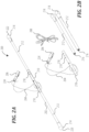
- FIG. 2A and FIG. 2B show a representative wand 200 formed in accordance with the present disclosure.
- the wand is collapsible, i.e ., it disassembles into a plurality of pieces.
- FIG. 2A shows the wand 200 in an assembled state
- FIG. 2B shows the wand 200 in a disassembled state.
- the assembled state shown in FIG. 2A is generally the state in which the wand 200 is utilized in creative routines
- the disassembled state is generally the state in which the wand 200 is stored, transported, etc.
- the wand 200 includes a wand portion 202, a tether 204, and an optional holding piece 206.
- the end caps 214 may be formed from a relatively soft material as compared to the poles 212 (e.g ., a relatively soft plastic, rubber, or foam) in order to absorb shock when the wand 200 is dropped.
- each end cap 214 has a maximum width that exceeds a maximum cross sectional diameter of the poles 212, such that the end cap 214 is more likely to contact the ground before the poles 212 when the wand 200 is dropped.
- the end caps 214 shown in FIG. 2A and FIG. 2B have a spherical shape; however any shape is possible.
- one or more of the end caps 214 has the shape of a magic wand, or a tip of a magic wand.
- the wand portion 202 has a length of between about 50 centimeters and about 150 centimeters (e.g ., 60 centimeters), measured from a first end 220 to a second end 222.
- the middle section 210 is between 10 centimeters and 20 centimeters long.
- each pole 212 and end section 214 (coupled together) is between 15 centimeters and 50 centimeters long ( e.g ., 23 cm).
- the wand portion 202 portion has a total weight of about 0.1 kilograms to about 1.0 kilogram ( e.g ., 0.11 kilograms).
- the middle section 210 weighs between 0.02 kilograms and 0.5 kilograms ( e.g ., about 0.04kg). In some embodiments, each coupled pole 212 and end section 214 weighs between 0.02 kilograms and 0.5 kilograms ( e.g ., about 0.04kg). In some embodiments, the poles 212 have different weights, which can advantageously cause the wand portion 202 to quickly return to a vertical orientation when suspended from the tether 204 (as shown in FIG. 1 ).
- a first pole 212 (coupled with a first end section 214) has a first weight
- a second pole 212 (connected with a second end section 214) has a second weight that is about 1% to about 20% greater than the first weight ( e.g ., about 7% greater).
- this difference between the first weight and the second weight is about 0.001 kilograms to about 0.100 kilograms.
- this difference between the first weight and the second weight is achieved by constructing the first pole 212 to a first length, and the second pole 212 to a different second length.
- the tether 204 is a length of cord, string, rope, cable, or the like having a length of about 50 centimeters to about 150 centimeters.
- the tether 204 is a string.
- the tether 204 is elasticized.
- the tether 204 is formed of two or more sections of material, rather than one continuous section of material.
- the tether 204 connects to the wand portion 202 at an off-center position, i.e ., a position on the wand portion 202 spaced apart from the longitudinal center of the wand portion 202.
- the tether 204 connects to the wand portion 202 at an off-center location spaced apart from the longitudinal center by 1 cm to 10cm. In such "off-center" embodiments, the wand 200 quickly returns to a "vertical" orientation when suspended from the tether 204. Details of the specific connections between the wand portion 202 and the tether 204 are described below.
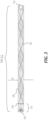
- FIG. 3 shows a representative pole 312 formed in accordance with the present disclosure and configured for coupling with a middle section of a wand portion, such as the middle section 210 of FIG. 2A .
- the pole 312 is at least partially formed of a durable, rigid, translucent or transparent material, for example acrylic or polycarbonate.
- translucent includes both translucent, partially opaque, and transparent materials, i.e ., materials that allow at least some visible light to pass therethrough.
- the translucent material allows the pole 312 to emit light, which makes the wand more entertaining and enhances creative routines.
- the pole 312 includes optional and integrally-formed passive light features 326 that reflect and/or refract light.
- the passive light features 326 include a plurality of etchings formed in an outer surface 328 of the pole 312, i.e ., helical etchings.
- the passive light features 326 include etchings having a different shape and/or size, e.g ., a spiral shape.
- the passive light features 326 include a different number of etchings.
- the pole 312 has an end cap connection portion 332 configured to couple with an end cap. (such as the end cap 214 of FIG. 2A and FIG. 2B ).
- the end cap connection portion 332 is a female recess configured to couple with a complementary male portion of an end cap.
- the end cap connection portion 332 is a threaded portion, a detent, or a similar feature.
- the pole 312 is configured to couple with the end cap by friction fit.
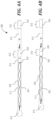
- FIG. 4A and FIG. 4B illustrate part of a representative wand portion of a wand 400 that is similar to the wand 200 of FIG. 2A and FIG. 2B .
- the wand 400 includes a middle section 410, a pole 412, and an end cap 414.
- the middle section 410 has a plurality of receiver portions 418, each forming a cavity with an open end facing axially away from the middle section 410 and configured to receive an insertion end 416 of the pole 412.
- the middle section 410 has a single receiver portion 418.
- the pole 412 includes a plurality of passive light features 426 (in this case, etchings) formed therein, which are configured to reflect and/or refract light in an aesthetically pleasing manner. Further, each receiver portion 418 further includes an annular shroud 434 having a longitudinal orientation relative to the middle section 410. The shrouds 434 are configured to cover a portion of the pole 412 when the wand 400 is in an assembled state. In addition, pole 412 includes an optional indicator 436 configured to prevent breakage of the pole 412 by ensuring correct insertion of the insertion end 416 with a receiver portion 418 of a middle section 410.
- the indicator 436 is a marking, a groove, a score a label, or the like placed on an outer surface 438 of the pole 412.
- the indicator 436 is located on the pole 412 such that it indicates when the pole 412 is properly inserted ( e.g. , threaded) into the receiver portion 418 of the middle section 410.
- the indicator 436 is located on the pole 412 at the insertion end 416. In some embodiments, the indicator 436 is spaced away from a most axially-distant point of the insertion end 416 by about 1cm to about 10cm, e.g ., 2cm. As shown in FIG. 4B , when the pole 412 is properly coupled with the receiver portion 418 of the middle section 410, the indicator 436 is adjacent to ( i.e ., visually "touches”) a most axially-distant point of the receiver portion 418, thus indicating that the pole 412 is properly coupled with the middle section 410.
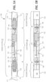
- FIG. 5A and FIG. 5B show a representative middle section 510 of a wand portion of a wand 500.
- the middle section 510 is reversibly coupled with two poles 512 in an assembled state.
- the middle section 510 is decoupled from any poles.
- the poles 512 are similar to the pole 312 of FIG. 3 .
- the middle section 510 and the poles 512 are configured such that poles 512 transmit light in the assembled state.
- the wand 500 includes a light engine 540 that transmits light through the poles 512, as described below.
- the middle section 510 and the poles 512 are configured to increase strength of the wand 500, and to facilitate assembly/disassembly.
- the middle section 510 includes an elongate, hollow outer housing 542 formed at least partially from a rugged material such as a metal and/or thermoplastic polymer.
- the outer housing 542 is substantially cylindrical.
- the outer housing 542 has a non-cylindrical cross section, e.g ., a hexagonal or octagonal cross section.
- the outer housing 542 is formed from a plurality of pieces, e.g ., a multi-piece "clamshell" type construction.
- the middle section 510 includes two axially-aligned receiver portions 518 located on either side of the light engine 540.
- each receiver portion 518 generally has a hollow or concave cavity 544 with an open end facing axially away from the middle section 510.
- Each receiver portion 518 is configured to reversibly couple with an insertion end 516 of one of the poles 512, e.g. , by insertion of the insertion end 516 into the cavity 544.
- each pole 512 is substantially the same and may be interchangeably coupled with either receiver portion 518.
- the poles 512 have different coupling structures or other features such that one pole 512 can be coupled only with one receiver portion 518.
- the middle section 510 has a single receiver portion 518.
- Each receiver portion 518 includes a shroud 534 (an annular cover) that covers the cavity 544, and which also covers at least a portion of the corresponding pole 512 ( e.g ., at least the insertion end 516 of the corresponding pole 512) when the wand 500 is in the assembled state, in order to prevent breakage when the wand 500 is dropped.
- the shrouds 534 may be formed from a rugged material such as a metal and/or thermoplastic polymer, in order to resist breaking when the wand 500 is dropped. In some embodiments, when the insertion end 516 of the pole 512 is received within the receiver portion 518, the shroud 534 covers about 1cm to about 10cm of the pole 512.
- each receiver portion 518 further includes a pin 546 configured to couple the insertion end 516 of one pole 512 with the outer housing 542.
- the pins 546 are not shown in FIG. 5B .
- Each pin 546 is formed of a translucent material, such that light emitted from the adjacent light engine 540 passes through the pin 546 and into the corresponding pole 512.
- the pin 546 is seated within or otherwise anchored to the outer housing 542, e.g ., at the pin seat 548 shown in FIG. 5B .
- the pin 546 has coupling structure that is complementary to the coupling structure of the insertion end 516 of the pole 512.
- FIG. 5A each receiver portion 518 further includes a pin 546 configured to couple the insertion end 516 of one pole 512 with the outer housing 542.
- the pins 546 are not shown in FIG. 5B .
- Each pin 546 is formed of a translucent material, such that light emitted from the adjacent light engine 540 passes through the pin 546 and into the
- the pin 546 has a male threaded coupling structure complementary to the female threaded coupling structure of the insertion end 516 of the pole 512. In some embodiments, the pin 546 has a female threaded coupling structure that is complementary to a male threaded coupling structure of the insertion end 516 of the pole 512. In some embodiments, the insertion end 516 and pin 546 have different complementary coupling structure ( i.e ., non-threaded coupling structure).
- the pin 546 is formed from a rigid but relatively soft material such as a thermoplastic polymer (e.g ., a translucent polymer), which in some embodiments is configured to absorb shock.
- the pin 546 absorbs shocks when the wand 500 is dropped, preventing breakage. In the unlikely event the pin 546 breaks, it can be replaced.
- the light engine 540 includes one or more lights and electronic elements that are together configured to project light in one or more directions and through one or more components of the wand 500, thereby making the wand 500 more entertaining.
- the light engine 540 includes two lights 550, a power source 552, and a controller 554 that are in electrical communication.
- the light engine 540 is configured to transmit light through one or more of the poles 512 which, as discussed above, may be at least partially constructed from a translucent material.
- the lights 550 are each light emitting diodes (LEDs), which are well-suited to the wand 500 because they are durable, energy efficient, bright, programmable to flash, change colors, etc., and offer other advantages. Nevertheless, in some embodiments, one or more lights 550 are an incandescent light, a fluorescent light, a chemical light ( e.g ., a glow stick), or another type of light. In FIG. 5A and FIG. 5B , the lights 550 are positioned on opposite sides of the controller 554. In particular, each light 550 is securely retained by the outer housing 542 such that it projects light in an axially-outward direction.
- LEDs light emitting diodes
- Each light 550 is positioned within the middle section 510 such that light emitted therefrom passes into the corresponding pole 512.
- each light 550 is positioned within the outer housing 542 (on opposite sides of the power source 552 and controller 554) such that light emitted therefrom passes through the corresponding translucent pin 546 and into the corresponding pole 512.
- each light 550 is positioned within the middle section 510 such that there is substantially no obstruction between the light 550 and the corresponding pole 512 in the assembled state.
- one or more of the lights 550 is located within one or more of the poles 512, such that the light 550 emits light directly from the one or more poles 512.
- each pole 512 having a light 550 positioned therein include electrical wiring, traces, and/or contacts that enable selective electrical connection between the pole 512 and the power source 552 when the pole 512 is assembled with the middle section 510.
- the threaded portions of poles 512 and the threaded portion of the pins 546 may each contain electrical contacts configured to achieve electrical connection when the poles 512 are connected to the middle section 510 in an axially-aligned assembly.
- the pins 546 and/or the outer housing 542 of the middle section 510 may also include electrical traces or contacts establishing electrical communication with the controller 554, or may themselves form part of one or more electrical circuits of the light engine 540.
- the power source 552 is a rechargeable battery, e.g ., a lithium-ion battery, nickel-cadmium battery, nickel metal hydride battery, or similar.
- the power source 552 is a non-rechargeable battery, e.g ., a disposable alkaline battery.
- the middle section 510 includes a charging interface 556 ( e.g ., a mini universal serial bus connection or similar connection) configured to receive a charging cord ( e.g ., the charging cord 208 of FIG. 2B ).
- a data store is a tangible machine-readable storage medium that includes any mechanism that provides (i.e ., stores) information in a non-transitory form accessible by a machine (e.g ., a computer, network device, personal digital assistant, manufacturing tool, any device with a set of one or more processors, etc.).
- a machine-readable storage medium includes recordable/non-recordable media (e.g ., read only memory (ROM), random access memory (RAM), magnetic disk storage media, optical storage media, flash memory devices, etc.).
- the modules 564 include one or more executable programs.
- the modules 564 include an on-off module 564 and a light mode module 564.
- the on-off module 564 cycles the lights 550 on and off in response to activation of the switch 558.
- the light mode module 564 cycles through a plurality of light modes when the switch 558 is activated in a particular sequence, e.g ., one or more fade light modes, one or more solid color light modes, one or more strobe light modes, etc.
- These modules 564 are representative and non-limiting. For example, different light modes not listed above are contemplated. While the representative wand 500 of FIG. 5 includes numerous modules 564, some embodiments include additional modules 564, fewer modules 564, or different modules 564.
- the controller 554 includes only a single module that turns the lights 550 on and off.
- the pole 712 has an insertion end 716 configured for insertion into a receiver portion of a middle section ( e.g ., the middle section 210 of FIG. 2A ). Whereas in FIG. 3 , the pole 312 is configured for threaded coupling with the receiver portion, the insertion end 716 of pole 712 has an elongate insertion portion 772 configured to couple with a receiver portion simply by insertion.
- the insertion portion 772 includes at least one engagement member 768 (e.g ., an O-ring) fitted thereto and configured to engage the receiver portion, thereby stably retaining the insertion portion 772 within the receiver portion of a compatible middle section, and thus coupling the pole 712 to the middle section.
- the receiver portion of the compatible middle section includes a retention portion (e.g ., a detent) configured to engage the engagement member 768 of the pole 712 when the insertion end 716 is inserted into the receiver portion.
- the insertion portion 772 has both a threaded portion (as in FIG. 3 ), and one or more engagement members 768.
- Representative wands include a light engine configured to transmit light through one or more portions of the wand such as one or more translucent poles.
- the light engine is programmed with one or more executable modules that cause one or more lights to change color, express an illumination pattern, etc.
- a plurality of poles are configured to couple with a middle section of the wand in a manner that improves durability and transmission of light from the light engine.
- Other representative wands are configured to break down from an axially-aligned assembled state to a disassembled state. Still other representative wands have particular features (e.g ., an off-center tether hole) configured to impart desirable balance characteristics.
- circuitry may utilize circuitry in order to implement technologies and methodologies described herein, operatively connect two or more components, generate information, determine operation conditions, control an appliance, device, or method, and/or the like.
- Circuitry of any type can be used.
- circuitry includes, among other things, one or more computing devices such as a processor (e.g ., a microprocessor), a central processing unit (CPU), a digital signal processor (DSP), an application-specific integrated circuit (ASIC), a fieldprogrammable gate array (FPGA), or the like, or any combinations thereof, and can include discrete digital or analog circuit elements or electronics, or combinations thereof.
- a processor e.g ., a microprocessor
- CPU central processing unit
- DSP digital signal processor
- ASIC application-specific integrated circuit
- FPGA fieldprogrammable gate array
- circuitry includes one or more ASICs having a plurality of predefined logic components.
- circuitry includes one or more FPGA having a plurality of programmable logic components.
- circuitry includes hardware circuit implementations ( e.g ., implementations in analog circuitry, implementations in digital circuitry, and the like, and combinations thereof).
- circuitry includes combinations of circuits and computer program products having software or firmware instructions stored on one or more computer readable memories that work together to cause a device to perform one or more methodologies or technologies described herein.
- circuitry includes circuits, such as, for example, microprocessors or portions of microprocessor, that require software, firmware, and the like for operation.
- circuitry includes an implementation comprising one or more processors or portions thereof and accompanying software, firmware, hardware, and the like.
- circuitry includes a baseband integrated circuit or applications processor integrated circuit or a similar integrated circuit in a server, a cellular network device, other network device, or other computing device.
- circuitry includes one or more remotely located components.
- remotely located components are operatively connected via wireless communication.
- remotely located components are operatively connected via one or more receivers, transmitters, transceivers, or the like.
- signal-bearing media include, but are not limited to, DVD-ROM, DVD-RAM, DVD+RW, DVD-RW, DVD-R, DVD+R, CD-ROM, Super Audio CD, CD-R, CD+R, CD+RW, CD-RW, Video Compact Discs, Super Video Discs, flash memory, magnetic tape, magneto-optic disk, MINIDISC, non-volatile memory card, EEPROM, optical disk, optical storage, RAM, ROM, system memory, web server, or the like.
Landscapes
- Engineering & Computer Science (AREA)
- General Engineering & Computer Science (AREA)
- Microelectronics & Electronic Packaging (AREA)
- Physics & Mathematics (AREA)
- General Physics & Mathematics (AREA)
- Optics & Photonics (AREA)
- Non-Portable Lighting Devices Or Systems Thereof (AREA)
- Planar Illumination Modules (AREA)
- Walking Sticks, Umbrellas, And Fans (AREA)
- Catching Or Destruction (AREA)
- Circuit Arrangements For Discharge Lamps (AREA)
- Illuminated Signs And Luminous Advertising (AREA)
Claims (15)
- Stab (100), umfassend:einen mittleren Abschnitt (210), der mindestens teilweise einen Lichtgenerator (540) aufnimmt;einen ersten Pol (212) und einen zweiten Pol (212), die jeweils dazu konfiguriert sind, sich reversibel an den mittleren Abschnitt in einer axial ausgerichteten Anordnung zu koppeln;eine Leine (204), die mit dem mittleren Abschnitt (210) verbunden ist;eine erste Endkappe (214), die an den ersten Pol (212) koppelbar ist; undeine zweite Endkappe (214), die an den zweiten Pol (212) koppelbar ist;wobei der Lichtgenerator (540) bewirkt, dass der erste Pol (212) und der zweite Pol (212) Licht übertragen.
- Stab (100) nach Anspruch 1, wobei der Lichtgenerator (540) mindestens eine Leuchte (550), eine Stromquelle (552) und ein Steuergerät (554) in elektrischer Kommunikation miteinander umfasst, wobei das Steuergerät (554) mit mindestens einem Modul (564) programmiert ist, das die Beleuchtung der mindestens einen Leuchte (550) steuert.
- Stab (100) nach Anspruch 2, wobei die mindestens eine Leuchte (550) eine erste Leuchte (550) und eine zweite Leuchte (550) beinhaltet, wobei die erste Leuchte (550) in dem mittleren Abschnitt (210) angrenzend an einen ersten Empfängerteil (218) davon angeordnet ist und die zweite Leuchts (550) in dem mittleren Abschnitt (210) angrenzend an einen zweiten Empfängerteil (218) davon angeordnet ist, wobei die erste Leuchte (550) und die zweite Leuchte (550) dazu konfiguriert sind, Licht axial nach außen von dem mittleren Abschnitt (210) durch den ersten Pol (212) beziehungsweise den zweiten Pol (212) zu übertragen.
- Stab (100) nach Anspruch 3, wobei das Steuergerät (554) und die Energiequelle (552) zwischen der ersten Leuchte (550) und der zweiten Leuchte (550) positioniert sind.
- Stab (100) nach Anspruch 2, wobei die mindestens eine Leuchte (550) eine erste Leuchte (550) und eine zweite Leuchte (550) beinhaltet, wobei die erste Leuchte (550) in dem ersten Pol (212) angeordnet ist und die zweite Leuchte (550) in dem zweiten Pol (212) angeordnet ist, wobei jeder des ersten Pols (212) und des zweiten Pols (212) einen elektrischen Kontakt aufweist, der eine elektrische Kommunikation mit dem Steuergerät (554) und der Stromquelle (552) herstellt, wenn der elektrische Kontakt an den mittleren Abschnitt (210) in der axial ausgerichteten Anordnung gekoppelt ist.
- Stab (100) nach Anspruch 1, wobei der erste Pol (212) und der zweite Pol (212) reversibel von dem mittleren Abschnitt (210) koppelbar sind, so dass der Stab (100) dazu konfiguriert ist, in einen demontierten Zustand zerlegt zu werden, in dem der erste Pol (212) und der zweite Pol (212) nicht mit dem mittleren Abschnitt (210) gekoppelt sind.
- Stab (100) nach Anspruch 1, wobei der mittlere Abschnitt (210) zwei axial ausgerichtete Aufnahmeteile (218) beinhaltet, die an gegenüberliegenden Enden davon angeordnet sind, wobei jeder Aufnahmeteil (218) einen Hohlraum (544) mit einem offenen Ende aufweist, das axial von dem mittleren Abschnitt (210) abgewandt ist, wobei jeder des ersten Pols (212) und des zweiten Pols (212) ein Einführungsende (216) aufweist, das zum Einführen in den Hohlraum (544) mindestens eines der beiden axial ausgerichteten Aufnahmeteile (218) konfiguriert ist.
- Stab (100) nach Anspruch 7, wobei jedes Einführungsende (216) einen Gewindeteil (330) beinhaltet und wobei jeder Aufnahmeteil (218) einen komplementären Gewindeteil beinhaltet.
- Stab nach Anspruch 8, wobei der komplementäre Gewindeteil des Aufnahmeteils (218) ein Gewindestift ist.
- Stab (100) nach Anspruch 7, wobei jedes Einführungsende (216) ein daran angebrachtes Eingriffselement (768) beinhaltet und jeder Aufnahmeteil (218) einen Halteteil aufweist, der dazu konfiguriert ist, das Eingriffselement (768) in Eingriff zu nehmen.
- Stab (100) nach Anspruch 7, wobei jeder Aufnahmeteil (218) eine Ummantelung (534) beinhaltet, die mindestens einen Teil des ersten Pols (212) oder des zweiten Pols (212) abdeckt, wenn der erste Pol (212) oder der zweite Pol (212) mit dem mittleren Abschnitt (218) gekoppelt ist.
- Stab (100) nach Anspruch 11, wobei die Abdeckung (534) dazu konfiguriert ist, etwa 1 cm bis etwa 10 cm des ersten Pols (212) oder des zweiten Pols (212) abzudecken.
- Stab (100) nach Anspruch 11, wobei die Ummantelung (534) dazu konfiguriert ist, mindestens teilweise einen Höchstdurchmesserteil des ersten Pols (212) oder einen Höchstdurchmesserteil des zweiten Pols (212) abzudecken.
- Stab nach Anspruch 1, wobei die Leine (204) durch ein Loch (566) in dem mittleren Abschnitt verläuft, das zwischen 1 cm und 10 cm von einer Längsmitte des mittleren Abschnitts (210) positioniert ist.
- Stab (100) nach Anspruch 1, wobei der erste Pol (212) ein erstes Gewicht aufweist und der zweite Pol (212) ein sich von dem ersten Gewicht unterscheidendes zweites Gewicht aufweist.
Applications Claiming Priority (3)
| Application Number | Priority Date | Filing Date | Title |
|---|---|---|---|
| US201962791580P | 2019-01-11 | 2019-01-11 | |
| US201962928273P | 2019-10-30 | 2019-10-30 | |
| PCT/US2020/013219 WO2020146824A1 (en) | 2019-01-11 | 2020-01-10 | Illuminated levitating wand |
Publications (4)
| Publication Number | Publication Date |
|---|---|
| EP3908144A1 EP3908144A1 (de) | 2021-11-17 |
| EP3908144A4 EP3908144A4 (de) | 2022-09-28 |
| EP3908144C0 EP3908144C0 (de) | 2023-12-13 |
| EP3908144B1 true EP3908144B1 (de) | 2023-12-13 |
Family
ID=71517516
Family Applications (1)
| Application Number | Title | Priority Date | Filing Date |
|---|---|---|---|
| EP20738890.1A Active EP3908144B1 (de) | 2019-01-11 | 2020-01-10 | Beleuchteter schwebender stab |
Country Status (9)
| Country | Link |
|---|---|
| US (2) | US10962179B2 (de) |
| EP (1) | EP3908144B1 (de) |
| JP (1) | JP7207788B2 (de) |
| KR (1) | KR102496083B1 (de) |
| CN (1) | CN113453581A (de) |
| AU (1) | AU2020206268B2 (de) |
| CA (1) | CA3126540C (de) |
| ES (1) | ES2966813T3 (de) |
| WO (1) | WO2020146824A1 (de) |
Families Citing this family (1)
| Publication number | Priority date | Publication date | Assignee | Title |
|---|---|---|---|---|
| CN113599835A (zh) * | 2021-07-20 | 2021-11-05 | 广州新起典文旅科技有限公司 | 一种智能互动权杖 |
Citations (1)
| Publication number | Priority date | Publication date | Assignee | Title |
|---|---|---|---|---|
| GB2582661A (en) * | 2019-03-29 | 2020-09-30 | Gary Shoveller Wayne | An illuminated wand |
Family Cites Families (27)
| Publication number | Priority date | Publication date | Assignee | Title |
|---|---|---|---|---|
| US2242981A (en) * | 1939-09-14 | 1941-05-20 | Christian R Pedersen | Illuminated twirling baton |
| US2911521A (en) * | 1957-12-16 | 1959-11-03 | Ferdinand C Schetz | Illuminator for lady's handbag |
| GB2068240A (en) * | 1980-01-09 | 1981-08-12 | Harbutts Plasticine Ltd | Magic wand |
| JPH0353297U (de) * | 1989-09-27 | 1991-05-23 | ||
| US5036442A (en) * | 1990-12-20 | 1991-07-30 | Brown Joseph T | Illuminated wand |
| US5356343A (en) * | 1992-07-29 | 1994-10-18 | Lovetere Christopher J | Flash magic wand |
| GB2277455A (en) * | 1993-01-19 | 1994-11-02 | Braeside Investment Trading In | Magic wand |
| US5432028A (en) | 1993-10-18 | 1995-07-11 | Westinghouse Electric Corporation | Electrolyte containment barrier for bipolar cells in high temperature molten salt batteries |
| GB2318747A (en) * | 1996-11-04 | 1998-05-06 | David Henry Colin Horsman | Wand |
| US6432028B1 (en) * | 1998-04-23 | 2002-08-13 | Angel Ortloff | Levitating exercise wand |
| US7445550B2 (en) * | 2000-02-22 | 2008-11-04 | Creative Kingdoms, Llc | Magical wand and interactive play experience |
| US6626728B2 (en) * | 2000-06-27 | 2003-09-30 | Kenneth C. Holt | Motion-sequence activated toy wand |
| US20030223247A1 (en) * | 2002-05-29 | 2003-12-04 | Sak Technologies, Inc. | Illumination device |
| DE20212529U1 (de) * | 2002-08-12 | 2003-01-02 | Zweibrüder Optoelectronics GmbH, 42699 Solingen | Stabförmige Lampe |
| CN2704388Y (zh) * | 2004-05-13 | 2005-06-15 | 苏武雄 | 水哑铃 |
| JP2006261076A (ja) * | 2005-03-15 | 2006-09-28 | Fuji Hightech Co Ltd | 懐中電灯 |
| TWM281251U (en) * | 2005-07-25 | 2005-11-21 | Jeng-Shi Chen | Command baton capable of being used as police baton and illumination flashlight |
| JP2011024949A (ja) * | 2009-07-29 | 2011-02-10 | Rmk Corporation:Kk | 発光風船及びその製造方法 |
| US8142295B2 (en) * | 2010-01-19 | 2012-03-27 | Yigal Mesika | Levitating disk |
| US7955157B1 (en) * | 2010-03-24 | 2011-06-07 | Hedeen International, Llc | Baton apparatus |
| JP5391235B2 (ja) * | 2011-06-23 | 2014-01-15 | 京楽産業.株式会社 | 発光遊技具 |
| JP3182303U (ja) * | 2012-12-25 | 2013-03-21 | 株式会社テラテック | 発光玩具 |
| CN203944135U (zh) * | 2014-02-17 | 2014-11-19 | 蔡逸纯 | 一种魔术棒 |
| US9586158B2 (en) * | 2015-03-17 | 2017-03-07 | William Mark Corporation | Telekinesis light wand |
| JP6429834B2 (ja) * | 2016-07-04 | 2018-11-28 | 株式会社エクスプロア | 発光表示スティック装置及び発光表示システム |
| EP3516296A4 (de) * | 2016-09-19 | 2020-06-03 | Dror Benshetrit | Technologien zur beleuchtung |
| US20180214785A1 (en) | 2017-02-02 | 2018-08-02 | Cepia Llc | Toy interactive entertainment devices |
-
2020
- 2020-01-10 EP EP20738890.1A patent/EP3908144B1/de active Active
- 2020-01-10 WO PCT/US2020/013219 patent/WO2020146824A1/en not_active Ceased
- 2020-01-10 CN CN202080011790.7A patent/CN113453581A/zh active Pending
- 2020-01-10 JP JP2021540308A patent/JP7207788B2/ja active Active
- 2020-01-10 KR KR1020217025237A patent/KR102496083B1/ko active Active
- 2020-01-10 ES ES20738890T patent/ES2966813T3/es active Active
- 2020-01-10 CA CA3126540A patent/CA3126540C/en active Active
- 2020-01-10 AU AU2020206268A patent/AU2020206268B2/en active Active
- 2020-01-10 US US16/740,307 patent/US10962179B2/en active Active
-
2021
- 2021-03-26 US US17/214,509 patent/US11486551B2/en active Active
Patent Citations (1)
| Publication number | Priority date | Publication date | Assignee | Title |
|---|---|---|---|---|
| GB2582661A (en) * | 2019-03-29 | 2020-09-30 | Gary Shoveller Wayne | An illuminated wand |
Also Published As
| Publication number | Publication date |
|---|---|
| KR20210118097A (ko) | 2021-09-29 |
| EP3908144A1 (de) | 2021-11-17 |
| JP2022508476A (ja) | 2022-01-19 |
| US20210215303A1 (en) | 2021-07-15 |
| WO2020146824A1 (en) | 2020-07-16 |
| CN113453581A (zh) | 2021-09-28 |
| EP3908144A4 (de) | 2022-09-28 |
| US10962179B2 (en) | 2021-03-30 |
| KR102496083B1 (ko) | 2023-02-06 |
| US20200224834A1 (en) | 2020-07-16 |
| CA3126540C (en) | 2023-04-18 |
| JP7207788B2 (ja) | 2023-01-18 |
| EP3908144C0 (de) | 2023-12-13 |
| BR112021013500A2 (pt) | 2021-09-14 |
| AU2020206268B2 (en) | 2022-03-24 |
| US11486551B2 (en) | 2022-11-01 |
| CA3126540A1 (en) | 2020-07-16 |
| ES2966813T3 (es) | 2024-04-24 |
| AU2020206268A1 (en) | 2021-09-02 |
Similar Documents
| Publication | Publication Date | Title |
|---|---|---|
| US6592423B1 (en) | Rotating holographic toy | |
| US20210332858A1 (en) | Customizable light-up device | |
| US10738972B1 (en) | Customizable light-up device | |
| JP6660916B2 (ja) | 演出出力玩具 | |
| CN101300510B (zh) | 发光棒 | |
| US11486551B2 (en) | Illuminated levitating wand | |
| TWI851604B (zh) | 桿、滑雪桿與健走杖的握把 | |
| US20060250797A1 (en) | Lighted hoop | |
| US20060135035A1 (en) | Remote control toy set | |
| US20120149444A1 (en) | Stand for wireless phone | |
| GB2242364A (en) | Portable articles with flashing lights e.g. balls, toys, signs | |
| CA2562525A1 (en) | Led illuminated glow stick | |
| US20140017973A1 (en) | Chinese Combination Toy for Children | |
| BR112021013500B1 (pt) | Varinha de levitação iluminada | |
| US11504594B1 (en) | Illuminated hockey puck assembly | |
| CN200948357Y (zh) | 一种摩擦搓动式玩具陀螺 | |
| KR101773899B1 (ko) | 원심력 기반 변신 완구 어셈블리 | |
| CN211798811U (zh) | 一种发光拼接模组 | |
| US9427614B1 (en) | Jump rope and music playing combination assembly | |
| KR102593969B1 (ko) | 앵두전구보관함 | |
| CN204107024U (zh) | 游戏手柄用发光按钮 | |
| JP3120504U (ja) | 組み合せ式電子装置 | |
| TWM546240U (zh) | 可產生電能、儲存電能及釋放電能的腕力球 | |
| EP1552868A1 (de) | Kreisel | |
| NL1016961C2 (nl) | Werpelement te gebruiken als speelgoed. |
Legal Events
| Date | Code | Title | Description |
|---|---|---|---|
| STAA | Information on the status of an ep patent application or granted ep patent |
Free format text: STATUS: THE INTERNATIONAL PUBLICATION HAS BEEN MADE |
|
| PUAI | Public reference made under article 153(3) epc to a published international application that has entered the european phase |
Free format text: ORIGINAL CODE: 0009012 |
|
| STAA | Information on the status of an ep patent application or granted ep patent |
Free format text: STATUS: REQUEST FOR EXAMINATION WAS MADE |
|
| 17P | Request for examination filed |
Effective date: 20210809 |
|
| AK | Designated contracting states |
Kind code of ref document: A1 Designated state(s): AL AT BE BG CH CY CZ DE DK EE ES FI FR GB GR HR HU IE IS IT LI LT LU LV MC MK MT NL NO PL PT RO RS SE SI SK SM TR |
|
| DAV | Request for validation of the european patent (deleted) | ||
| DAX | Request for extension of the european patent (deleted) | ||
| A4 | Supplementary search report drawn up and despatched |
Effective date: 20220831 |
|
| RIC1 | Information provided on ipc code assigned before grant |
Ipc: F21L 4/00 20060101ALI20220825BHEP Ipc: A63J 21/00 20060101ALI20220825BHEP Ipc: A63H 33/26 20060101ALI20220825BHEP Ipc: A45B 3/04 20060101AFI20220825BHEP |
|
| GRAP | Despatch of communication of intention to grant a patent |
Free format text: ORIGINAL CODE: EPIDOSNIGR1 |
|
| STAA | Information on the status of an ep patent application or granted ep patent |
Free format text: STATUS: GRANT OF PATENT IS INTENDED |
|
| INTG | Intention to grant announced |
Effective date: 20230612 |
|
| GRAS | Grant fee paid |
Free format text: ORIGINAL CODE: EPIDOSNIGR3 |
|
| GRAA | (expected) grant |
Free format text: ORIGINAL CODE: 0009210 |
|
| STAA | Information on the status of an ep patent application or granted ep patent |
Free format text: STATUS: THE PATENT HAS BEEN GRANTED |
|
| RAP3 | Party data changed (applicant data changed or rights of an application transferred) |
Owner name: SCHLAPIK, KEVIN D. |
|
| RIN1 | Information on inventor provided before grant (corrected) |
Inventor name: SCHLAPIK, KEVIN D. |
|
| AK | Designated contracting states |
Kind code of ref document: B1 Designated state(s): AL AT BE BG CH CY CZ DE DK EE ES FI FR GB GR HR HU IE IS IT LI LT LU LV MC MK MT NL NO PL PT RO RS SE SI SK SM TR |
|
| REG | Reference to a national code |
Ref country code: GB Ref legal event code: FG4D |
|
| REG | Reference to a national code |
Ref country code: CH Ref legal event code: EP |
|
| REG | Reference to a national code |
Ref country code: DE Ref legal event code: R096 Ref document number: 602020022714 Country of ref document: DE |
|
| REG | Reference to a national code |
Ref country code: IE Ref legal event code: FG4D |
|
| U01 | Request for unitary effect filed |
Effective date: 20231213 |
|
| U07 | Unitary effect registered |
Designated state(s): AT BE BG DE DK EE FI FR IT LT LU LV MT NL PT SE SI Effective date: 20231219 |
|
| PG25 | Lapsed in a contracting state [announced via postgrant information from national office to epo] |
Ref country code: GR Free format text: LAPSE BECAUSE OF FAILURE TO SUBMIT A TRANSLATION OF THE DESCRIPTION OR TO PAY THE FEE WITHIN THE PRESCRIBED TIME-LIMIT Effective date: 20240314 |
|
| U20 | Renewal fee for the european patent with unitary effect paid |
Year of fee payment: 5 Effective date: 20240305 |
|
| REG | Reference to a national code |
Ref country code: ES Ref legal event code: FG2A Ref document number: 2966813 Country of ref document: ES Kind code of ref document: T3 Effective date: 20240424 |
|
| PG25 | Lapsed in a contracting state [announced via postgrant information from national office to epo] |
Ref country code: GR Free format text: LAPSE BECAUSE OF FAILURE TO SUBMIT A TRANSLATION OF THE DESCRIPTION OR TO PAY THE FEE WITHIN THE PRESCRIBED TIME-LIMIT Effective date: 20240314 |
|
| PG25 | Lapsed in a contracting state [announced via postgrant information from national office to epo] |
Ref country code: RS Free format text: LAPSE BECAUSE OF FAILURE TO SUBMIT A TRANSLATION OF THE DESCRIPTION OR TO PAY THE FEE WITHIN THE PRESCRIBED TIME-LIMIT Effective date: 20231213 Ref country code: NO Free format text: LAPSE BECAUSE OF FAILURE TO SUBMIT A TRANSLATION OF THE DESCRIPTION OR TO PAY THE FEE WITHIN THE PRESCRIBED TIME-LIMIT Effective date: 20240313 Ref country code: HR Free format text: LAPSE BECAUSE OF FAILURE TO SUBMIT A TRANSLATION OF THE DESCRIPTION OR TO PAY THE FEE WITHIN THE PRESCRIBED TIME-LIMIT Effective date: 20231213 |
|
| PG25 | Lapsed in a contracting state [announced via postgrant information from national office to epo] |
Ref country code: IS Free format text: LAPSE BECAUSE OF FAILURE TO SUBMIT A TRANSLATION OF THE DESCRIPTION OR TO PAY THE FEE WITHIN THE PRESCRIBED TIME-LIMIT Effective date: 20240413 |
|
| PG25 | Lapsed in a contracting state [announced via postgrant information from national office to epo] |
Ref country code: CZ Free format text: LAPSE BECAUSE OF FAILURE TO SUBMIT A TRANSLATION OF THE DESCRIPTION OR TO PAY THE FEE WITHIN THE PRESCRIBED TIME-LIMIT Effective date: 20231213 |
|
| PG25 | Lapsed in a contracting state [announced via postgrant information from national office to epo] |
Ref country code: SK Free format text: LAPSE BECAUSE OF FAILURE TO SUBMIT A TRANSLATION OF THE DESCRIPTION OR TO PAY THE FEE WITHIN THE PRESCRIBED TIME-LIMIT Effective date: 20231213 |
|
| PG25 | Lapsed in a contracting state [announced via postgrant information from national office to epo] |
Ref country code: SM Free format text: LAPSE BECAUSE OF FAILURE TO SUBMIT A TRANSLATION OF THE DESCRIPTION OR TO PAY THE FEE WITHIN THE PRESCRIBED TIME-LIMIT Effective date: 20231213 Ref country code: SK Free format text: LAPSE BECAUSE OF FAILURE TO SUBMIT A TRANSLATION OF THE DESCRIPTION OR TO PAY THE FEE WITHIN THE PRESCRIBED TIME-LIMIT Effective date: 20231213 Ref country code: RO Free format text: LAPSE BECAUSE OF FAILURE TO SUBMIT A TRANSLATION OF THE DESCRIPTION OR TO PAY THE FEE WITHIN THE PRESCRIBED TIME-LIMIT Effective date: 20231213 Ref country code: IS Free format text: LAPSE BECAUSE OF FAILURE TO SUBMIT A TRANSLATION OF THE DESCRIPTION OR TO PAY THE FEE WITHIN THE PRESCRIBED TIME-LIMIT Effective date: 20240413 Ref country code: CZ Free format text: LAPSE BECAUSE OF FAILURE TO SUBMIT A TRANSLATION OF THE DESCRIPTION OR TO PAY THE FEE WITHIN THE PRESCRIBED TIME-LIMIT Effective date: 20231213 |
|
| PG25 | Lapsed in a contracting state [announced via postgrant information from national office to epo] |
Ref country code: PL Free format text: LAPSE BECAUSE OF FAILURE TO SUBMIT A TRANSLATION OF THE DESCRIPTION OR TO PAY THE FEE WITHIN THE PRESCRIBED TIME-LIMIT Effective date: 20231213 |
|
| PG25 | Lapsed in a contracting state [announced via postgrant information from national office to epo] |
Ref country code: PL Free format text: LAPSE BECAUSE OF FAILURE TO SUBMIT A TRANSLATION OF THE DESCRIPTION OR TO PAY THE FEE WITHIN THE PRESCRIBED TIME-LIMIT Effective date: 20231213 |
|
| REG | Reference to a national code |
Ref country code: CH Ref legal event code: PL |
|
| REG | Reference to a national code |
Ref country code: DE Ref legal event code: R097 Ref document number: 602020022714 Country of ref document: DE |
|
| PG25 | Lapsed in a contracting state [announced via postgrant information from national office to epo] |
Ref country code: MC Free format text: LAPSE BECAUSE OF FAILURE TO SUBMIT A TRANSLATION OF THE DESCRIPTION OR TO PAY THE FEE WITHIN THE PRESCRIBED TIME-LIMIT Effective date: 20231213 |
|
| PLBE | No opposition filed within time limit |
Free format text: ORIGINAL CODE: 0009261 |
|
| STAA | Information on the status of an ep patent application or granted ep patent |
Free format text: STATUS: NO OPPOSITION FILED WITHIN TIME LIMIT |
|
| PG25 | Lapsed in a contracting state [announced via postgrant information from national office to epo] |
Ref country code: CH Free format text: LAPSE BECAUSE OF NON-PAYMENT OF DUE FEES Effective date: 20240131 |
|
| PG25 | Lapsed in a contracting state [announced via postgrant information from national office to epo] |
Ref country code: CH Free format text: LAPSE BECAUSE OF NON-PAYMENT OF DUE FEES Effective date: 20240131 |
|
| 26N | No opposition filed |
Effective date: 20240916 |
|
| U20 | Renewal fee for the european patent with unitary effect paid |
Year of fee payment: 6 Effective date: 20241203 |
|
| PG25 | Lapsed in a contracting state [announced via postgrant information from national office to epo] |
Ref country code: IE Free format text: LAPSE BECAUSE OF NON-PAYMENT OF DUE FEES Effective date: 20240110 |
|
| PG25 | Lapsed in a contracting state [announced via postgrant information from national office to epo] |
Ref country code: IE Free format text: LAPSE BECAUSE OF NON-PAYMENT OF DUE FEES Effective date: 20240110 |
|
| PG25 | Lapsed in a contracting state [announced via postgrant information from national office to epo] |
Ref country code: CY Free format text: LAPSE BECAUSE OF FAILURE TO SUBMIT A TRANSLATION OF THE DESCRIPTION OR TO PAY THE FEE WITHIN THE PRESCRIBED TIME-LIMIT; INVALID AB INITIO Effective date: 20200110 |
|
| PG25 | Lapsed in a contracting state [announced via postgrant information from national office to epo] |
Ref country code: HU Free format text: LAPSE BECAUSE OF FAILURE TO SUBMIT A TRANSLATION OF THE DESCRIPTION OR TO PAY THE FEE WITHIN THE PRESCRIBED TIME-LIMIT; INVALID AB INITIO Effective date: 20200110 |
|
| PG25 | Lapsed in a contracting state [announced via postgrant information from national office to epo] |
Ref country code: TR Free format text: LAPSE BECAUSE OF FAILURE TO SUBMIT A TRANSLATION OF THE DESCRIPTION OR TO PAY THE FEE WITHIN THE PRESCRIBED TIME-LIMIT Effective date: 20231213 |
|
| U20 | Renewal fee for the european patent with unitary effect paid |
Year of fee payment: 7 Effective date: 20260128 |
|
| PGFP | Annual fee paid to national office [announced via postgrant information from national office to epo] |
Ref country code: GB Payment date: 20260121 Year of fee payment: 7 |
|
| PGFP | Annual fee paid to national office [announced via postgrant information from national office to epo] |
Ref country code: ES Payment date: 20260217 Year of fee payment: 7 |