EP3908095A1 - Hybrid cooling for power electronics unit - Google Patents
Hybrid cooling for power electronics unit Download PDFInfo
- Publication number
- EP3908095A1 EP3908095A1 EP21170642.9A EP21170642A EP3908095A1 EP 3908095 A1 EP3908095 A1 EP 3908095A1 EP 21170642 A EP21170642 A EP 21170642A EP 3908095 A1 EP3908095 A1 EP 3908095A1
- Authority
- EP
- European Patent Office
- Prior art keywords
- electronics unit
- power electronics
- working fluid
- heat
- compressor
- Prior art date
- Legal status (The legal status is an assumption and is not a legal conclusion. Google has not performed a legal analysis and makes no representation as to the accuracy of the status listed.)
- Granted
Links
Images



Classifications
-
- F—MECHANICAL ENGINEERING; LIGHTING; HEATING; WEAPONS; BLASTING
- F25—REFRIGERATION OR COOLING; COMBINED HEATING AND REFRIGERATION SYSTEMS; HEAT PUMP SYSTEMS; MANUFACTURE OR STORAGE OF ICE; LIQUEFACTION SOLIDIFICATION OF GASES
- F25B—REFRIGERATION MACHINES, PLANTS OR SYSTEMS; COMBINED HEATING AND REFRIGERATION SYSTEMS; HEAT PUMP SYSTEMS
- F25B1/00—Compression machines, plants or systems with non-reversible cycle
-
- H—ELECTRICITY
- H05—ELECTRIC TECHNIQUES NOT OTHERWISE PROVIDED FOR
- H05K—PRINTED CIRCUITS; CASINGS OR CONSTRUCTIONAL DETAILS OF ELECTRIC APPARATUS; MANUFACTURE OF ASSEMBLAGES OF ELECTRICAL COMPONENTS
- H05K7/00—Constructional details common to different types of electric apparatus
- H05K7/20—Modifications to facilitate cooling, ventilating, or heating
- H05K7/2029—Modifications to facilitate cooling, ventilating, or heating using a liquid coolant with phase change in electronic enclosures
- H05K7/20354—Refrigerating circuit comprising a compressor
-
- F—MECHANICAL ENGINEERING; LIGHTING; HEATING; WEAPONS; BLASTING
- F25—REFRIGERATION OR COOLING; COMBINED HEATING AND REFRIGERATION SYSTEMS; HEAT PUMP SYSTEMS; MANUFACTURE OR STORAGE OF ICE; LIQUEFACTION SOLIDIFICATION OF GASES
- F25B—REFRIGERATION MACHINES, PLANTS OR SYSTEMS; COMBINED HEATING AND REFRIGERATION SYSTEMS; HEAT PUMP SYSTEMS
- F25B31/00—Compressor arrangements
- F25B31/006—Cooling of compressor or motor
-
- F—MECHANICAL ENGINEERING; LIGHTING; HEATING; WEAPONS; BLASTING
- F25—REFRIGERATION OR COOLING; COMBINED HEATING AND REFRIGERATION SYSTEMS; HEAT PUMP SYSTEMS; MANUFACTURE OR STORAGE OF ICE; LIQUEFACTION SOLIDIFICATION OF GASES
- F25B—REFRIGERATION MACHINES, PLANTS OR SYSTEMS; COMBINED HEATING AND REFRIGERATION SYSTEMS; HEAT PUMP SYSTEMS
- F25B5/00—Compression machines, plants or systems, with several evaporator circuits, e.g. for varying refrigerating capacity
- F25B5/02—Compression machines, plants or systems, with several evaporator circuits, e.g. for varying refrigerating capacity arranged in parallel
-
- H—ELECTRICITY
- H05—ELECTRIC TECHNIQUES NOT OTHERWISE PROVIDED FOR
- H05K—PRINTED CIRCUITS; CASINGS OR CONSTRUCTIONAL DETAILS OF ELECTRIC APPARATUS; MANUFACTURE OF ASSEMBLAGES OF ELECTRICAL COMPONENTS
- H05K7/00—Constructional details common to different types of electric apparatus
- H05K7/20—Modifications to facilitate cooling, ventilating, or heating
- H05K7/20009—Modifications to facilitate cooling, ventilating, or heating using a gaseous coolant in electronic enclosures
- H05K7/20136—Forced ventilation, e.g. by fans
-
- H—ELECTRICITY
- H05—ELECTRIC TECHNIQUES NOT OTHERWISE PROVIDED FOR
- H05K—PRINTED CIRCUITS; CASINGS OR CONSTRUCTIONAL DETAILS OF ELECTRIC APPARATUS; MANUFACTURE OF ASSEMBLAGES OF ELECTRICAL COMPONENTS
- H05K7/00—Constructional details common to different types of electric apparatus
- H05K7/20—Modifications to facilitate cooling, ventilating, or heating
- H05K7/20009—Modifications to facilitate cooling, ventilating, or heating using a gaseous coolant in electronic enclosures
- H05K7/20136—Forced ventilation, e.g. by fans
- H05K7/20154—Heat dissipaters coupled to components
-
- H—ELECTRICITY
- H05—ELECTRIC TECHNIQUES NOT OTHERWISE PROVIDED FOR
- H05K—PRINTED CIRCUITS; CASINGS OR CONSTRUCTIONAL DETAILS OF ELECTRIC APPARATUS; MANUFACTURE OF ASSEMBLAGES OF ELECTRICAL COMPONENTS
- H05K7/00—Constructional details common to different types of electric apparatus
- H05K7/20—Modifications to facilitate cooling, ventilating, or heating
- H05K7/20218—Modifications to facilitate cooling, ventilating, or heating using a liquid coolant without phase change in electronic enclosures
- H05K7/20281—Thermal management, e.g. liquid flow control
-
- H—ELECTRICITY
- H05—ELECTRIC TECHNIQUES NOT OTHERWISE PROVIDED FOR
- H05K—PRINTED CIRCUITS; CASINGS OR CONSTRUCTIONAL DETAILS OF ELECTRIC APPARATUS; MANUFACTURE OF ASSEMBLAGES OF ELECTRICAL COMPONENTS
- H05K7/00—Constructional details common to different types of electric apparatus
- H05K7/20—Modifications to facilitate cooling, ventilating, or heating
- H05K7/2029—Modifications to facilitate cooling, ventilating, or heating using a liquid coolant with phase change in electronic enclosures
- H05K7/20309—Evaporators
-
- H—ELECTRICITY
- H05—ELECTRIC TECHNIQUES NOT OTHERWISE PROVIDED FOR
- H05K—PRINTED CIRCUITS; CASINGS OR CONSTRUCTIONAL DETAILS OF ELECTRIC APPARATUS; MANUFACTURE OF ASSEMBLAGES OF ELECTRICAL COMPONENTS
- H05K7/00—Constructional details common to different types of electric apparatus
- H05K7/20—Modifications to facilitate cooling, ventilating, or heating
- H05K7/2029—Modifications to facilitate cooling, ventilating, or heating using a liquid coolant with phase change in electronic enclosures
- H05K7/20318—Condensers
-
- H—ELECTRICITY
- H05—ELECTRIC TECHNIQUES NOT OTHERWISE PROVIDED FOR
- H05K—PRINTED CIRCUITS; CASINGS OR CONSTRUCTIONAL DETAILS OF ELECTRIC APPARATUS; MANUFACTURE OF ASSEMBLAGES OF ELECTRICAL COMPONENTS
- H05K7/00—Constructional details common to different types of electric apparatus
- H05K7/20—Modifications to facilitate cooling, ventilating, or heating
- H05K7/2089—Modifications to facilitate cooling, ventilating, or heating for power electronics, e.g. for inverters for controlling motor
- H05K7/20909—Forced ventilation, e.g. on heat dissipaters coupled to components
-
- H—ELECTRICITY
- H05—ELECTRIC TECHNIQUES NOT OTHERWISE PROVIDED FOR
- H05K—PRINTED CIRCUITS; CASINGS OR CONSTRUCTIONAL DETAILS OF ELECTRIC APPARATUS; MANUFACTURE OF ASSEMBLAGES OF ELECTRICAL COMPONENTS
- H05K7/00—Constructional details common to different types of electric apparatus
- H05K7/20—Modifications to facilitate cooling, ventilating, or heating
- H05K7/2089—Modifications to facilitate cooling, ventilating, or heating for power electronics, e.g. for inverters for controlling motor
- H05K7/20936—Liquid coolant with phase change
-
- F—MECHANICAL ENGINEERING; LIGHTING; HEATING; WEAPONS; BLASTING
- F25—REFRIGERATION OR COOLING; COMBINED HEATING AND REFRIGERATION SYSTEMS; HEAT PUMP SYSTEMS; MANUFACTURE OR STORAGE OF ICE; LIQUEFACTION SOLIDIFICATION OF GASES
- F25B—REFRIGERATION MACHINES, PLANTS OR SYSTEMS; COMBINED HEATING AND REFRIGERATION SYSTEMS; HEAT PUMP SYSTEMS
- F25B2600/00—Control issues
- F25B2600/02—Compressor control
- F25B2600/025—Compressor control by controlling speed
- F25B2600/0253—Compressor control by controlling speed with variable speed
-
- Y—GENERAL TAGGING OF NEW TECHNOLOGICAL DEVELOPMENTS; GENERAL TAGGING OF CROSS-SECTIONAL TECHNOLOGIES SPANNING OVER SEVERAL SECTIONS OF THE IPC; TECHNICAL SUBJECTS COVERED BY FORMER USPC CROSS-REFERENCE ART COLLECTIONS [XRACs] AND DIGESTS
- Y02—TECHNOLOGIES OR APPLICATIONS FOR MITIGATION OR ADAPTATION AGAINST CLIMATE CHANGE
- Y02B—CLIMATE CHANGE MITIGATION TECHNOLOGIES RELATED TO BUILDINGS, e.g. HOUSING, HOUSE APPLIANCES OR RELATED END-USER APPLICATIONS
- Y02B30/00—Energy efficient heating, ventilation or air conditioning [HVAC]
- Y02B30/70—Efficient control or regulation technologies, e.g. for control of refrigerant flow, motor or heating
Definitions
- Refrigerated trucks and trailers are commonly used to transport perishable goods, such as, for example, produce, meat, poultry, fish, dairy products, cut flowers, and other fresh or frozen perishable products.
- a transport refrigeration unit TRU
- the transport refrigeration unit includes a compressor to circulate the refrigerant within the transport refrigeration unit.
- the compressor may be driven either mechanically (e.g., using a direct mechanical coupling or belt drive) or electrically. When mechanically driven, the compressor derives power from the vehicle engine. When electrically driven, the compressor can derive power either from a generator or an onboard battery.
- the duty cycle of the compressor may vary depending on various factors, such as, for example, the ambient temperature, type and volume of cargo, the desired temperature for the cargo space, and the frequency and length of time that the cargo space is opened for loading or unloading.
- the compressor may be functioning at less than full capacity and, at times, may be completely shut off.
- One way in which the operation of the compressor may be controlled is through use a power electronics unit.
- a power electronics unit may be used to selectively vary the power being supplied to the compressor (e.g., by varying the current, voltage, and/or frequency).
- the power electronics unit when included, may be a critical component for the transport refrigeration unit.
- the power electronics unit may overheat, which may damage the circuit components within the power electronics unit (e.g., potential making the power electronics unit inoperable) and/or present a product safety issue (e.g., due to the generation of heat).
- liquid cooling has been explored.
- prior transport refrigeration units have included the power electronics unit within the vapor compression cycle of the transport refrigeration unit, where the entire power electronics unit is cooled by passing the entire volume of refrigerant through the power electronics unit (e.g., in series with the compressor).
- cooling the entire power electronics unit with refrigerant from the transport refrigeration unit may impact the ability of the transport refrigeration unit to provide efficient cooling for the perishable goods, as adding a heat source (i.e., the power electronics unit) will increase the cooling load.
- a vapor compression system includes a compressor, an evaporator, and a power electronics unit.
- the compressor includes an electric drive motor for increasing the pressure of a working fluid.
- the evaporator is in fluid communication with the compressor.
- the evaporator is configured to transfer heat from an external medium to the working fluid.
- the power electronics unit is used for controlling the transfer of an electrical power to the electric drive motor.
- the power electronics unit includes a semiconductor portion and an inductor portion.
- the semiconductor portion includes at least one fan configured to transfer heat from the semiconductor portion.
- the inductor portion includes at least one conduit configured to receive at least a portion of the working fluid.
- the working fluid is configured to transfer heat from the inductor portion.
- the inductor portion may receive at least a portion of the working fluid from upstream of the evaporator.
- the working fluid from the inductor portion may be transferred to the compressor.
- the working fluid from the inductor portion may be transferred to the evaporator.
- the heat generated by the power electronics unit may be proportional to the transfer of the electrical power to the electric drive motor.
- At least 60% of the heat generated by the power electronics unit may be derived from the semiconductor portion.
- the at least one fan may transfer substantially all of the heat derived from the semiconductor portion.
- the working fluid may transfer substantially all of the heat derived from the inductor portion.
- the working fluid may be a refrigerant.
- a power electronics unit including a semiconductor portion and an inductor portion.
- the semiconductor portion includes at least one fan configured to transfer heat from the semiconductor portion.
- the inductor portion includes at least one conduit configured to receive a working fluid. The working fluid is configured to transfer heat from the inductor portion.
- At least 60% of the heat generated by the power electronics unit may be derived from the semiconductor portion.
- the at least one fan may transfer substantially all of the heat derived from the semiconductor portion.
- the working fluid may transfer substantially all of the heat derived from the inductor portion.
- a method of cooling a power electronics unit includes a semiconductor portion with at least one fan, and an inductor portion with at least one conduit.
- the method includes a step for passing a working fluid through the conduit.
- the working fluid transferring heat from the inductor portion.
- the method includes a step for operating at least one fan to transfer heat from the semiconductor portion.
- the method further includes transferring an electrical power from the power electronics unit to an electric drive motor of a compressor, the compressor configured to change the pressure of the working fluid.
- the heat generated by the power electronics unit may be proportional to the transfer of the electrical power to the electric drive motor.
- At least 60% of the heat generated by the power electronics unit may be derived from the semiconductor portion, substantially all of the heat derived from the semiconductor may be transferred by the at least one fan.
- Vapor compression systems commonly include a compressor, a condenser, an expansion valve, and an evaporator.
- Refrigerant circulates through the vapor compression system in order to provide cooling to a medium (e.g., the air within the cargo space of the truck/trailer).
- the refrigerant exits the compressor through a discharge port at a high pressure and a high enthalpy.
- the refrigerant then flows through the condenser at a high pressure and rejects heat to an external fluid medium (e.g., an air supply or a water supply).
- the refrigerant then flows through the expansion valve, which expands the refrigerant to a low pressure. After expansion, the refrigerant flows through the evaporator and absorbs heat from another medium (e.g., air).
- the refrigerant then re-enters the compressor through a suction port, completing the cycle.
- the operation e.g., the speed
- the refrigerant may be circulated within the vapor compression system at an increased rate
- the refrigerant may be circulated at a slower rate.
- a power electronics unit may be utilized. It should be understood that the power electronics unit may be any electronic device/system that is capable of varying the speed of the compressor.
- the power electronics unit may include multiple components, each of which may necessitate different amounts of cooling. For example, particular components may produce more heat and thus may require more cooling.
- At least a portion of the power electronics unit is cooled using at least a portion of the refrigerant from a vapor compression system (e.g., of a transport refrigeration unit).
- a hybrid cooling system is provided.
- a hybrid cooling system is a system that incorporates both forced air cooling and liquid cooling.
- FIG. 1 a schematic illustration of a vapor compression system 100 including a compressor 110, a condenser 150, an evaporator 120, and an expansion valve 140, with a power electronics unit 130 receiving a working fluid from upstream of the evaporator 120 is shown in FIG. 1 .
- the working fluid may be any fluid capable of transferring heat (e.g., water, refrigerant, brine, etc.).
- the driving force of the working fluid through the power electronics unit 130 may be the compressor 110 from the vapor compression system 100 (e.g., where no additional compressor or pump is needed separate from the existing compressor 110 of the vapor compressions system 100).
- the compressor 110 includes an electric drive motor 111 for increasing the pressure of the working fluid.
- the electric drive motor 111 may be an AC or DC motor, which may be mounted to the compressor 110.
- the evaporator 120 is in fluid communication with the compressor 110. Being in fluid communication may be interpreted to mean that the evaporator 120 and the compressor 110 are included within the same vapor compression system 100 (e.g., where the working fluid that is passed through evaporator 120 is also passed through the compressor 110).
- the evaporator 120 is configured to transfer heat from an external medium (e.g., an air supply or a water supply) to the working fluid.
- the power electronics unit 130 is used to control the transfer of an electrical power (e.g., from an on-board battery within the transport refrigeration unit) to the electric drive motor 111 (e.g., through one or more wired connections).
- the power electronics unit 130 includes a semiconductor portion 132 and an inductor portion 131.
- the semiconductor portion 132 includes at least one fan 133 configured to transfer heat from the semiconductor portion 132.
- the inductor portion 131 includes at least one conduit 134 configured to receive at least a portion of the working fluid (e.g., from upstream of the evaporator 120). The working fluid is used to transfer heat from the inductor portion 131.
- the working fluid may be sent either to the compressor 110 (as shown in FIG. 1 ), or to the evaporator 120 (as shown in FIG. 2 ). In certain instances, the working fluid may be sent from the power electronics unit 130 to both the compressor 110 and the evaporator 120. For example, a portion of the working fluid may be sent from the power electronics unit 130 to the compressor 110 and a portion of the working fluid may be sent from the power electronics unit 130 to the evaporator 120. It may be advantageous to send the working fluid from the power electronics unit 130 to the evaporator 120 when the heat produced by the inductor portion 131 is not sufficiently high enough to utilize the entire cooling capacity of the working fluid. Conversely, it may be advantageous to send the working fluid from the power electronics unit 130 to the compressor 110 when the heat produced by the inductor portion 131 is sufficiently high enough to utilize majority of the cooling capacity of the working fluid.
- the heat generated by the power electronics unit 130 may be proportional to the transfer of the electrical power to the electric drive motor 111 of the compressor 110.
- the power electronics unit 130 may generate more heat when more electrical power is transferred to the electric drive motor 111, and may generate less heat when less electrical power is transferred to the electric drive motor 111.
- the power electronics unit 130 may generate more heat in one portion than another.
- the semiconductor portion 132 may generate more heat than the inductor portion 131.
- at least 60% of the heat generated by the power electronics unit 130 is derived from the semiconductor portion 132.
- less than 40% of the heat generated by the power electronics unit 130 is derived from the inductor portion 131.
- the semiconductor portion 132 may be air cooled (e.g., using one or more fan 133).
- At least one fan 133 may be used to transfer substantially all of the heat derived from the semiconductor portion 132. This may be interpreted to mean that the semiconductor portion 132 may not be cooled using any of the cooling capacity of the working fluid. Instead of cooling both the semiconductor portion 132 and the inductor portion 131 with working fluid, the system 100 solely uses working fluid to cool the inductor portion 131. In certain instances, the working fluid transfers substantially all of the heat derived from the inductor portion 131. This may be interpreted to mean that the inductor portion may only be cooled using working fluid. However, it should be appreciated that one or more fan 133 may be used to remove at least a portion of the generated by the inductor portion 131.
- the fan 133 for the semiconductor portion 132 may be configured to direct an airflow over both the semiconductor portion 132 and the inductor portion 131. It is envisioned, however, that the inductor portion 131 may have a separate fan (not shown) dedicated to cooling the inductor portion 131.
- the impact of the power electronics unit 130 on the vapor compression system 100 is minimized (e.g., by at least 60% compared to processes utilizing liquid cooling for the entire power electronics unit 130).
- this system 100 utilizes a hybrid cooling technique to only provide liquid cooling to the inductor portion 131.
- the inductor portion 131 is responsible for less than 40% of the heat generated by the power electronics unit 130, with the remaining amount (e.g., at least 60%) of the heat being attributable to the semiconductor portion 132, which is cooled using at least one fan 133.
- the ability to limit liquid cooling to only the inductor portion 131 may be possible because of the shape of the components (e.g., the shape of the semiconductor portion 132).
- the semiconductor portion 132 may be designed to be relatively flat, which may make the semiconductor portion 132 easier to cool with air (e.g., with one or more fan 133 disposed near the semiconductor portion 132) than the inductor portion 131 (e.g., which may have a complex three-dimensional structure).
- one or more conduits 134 may be used to circulate working fluid (e.g., refrigerant) either around or through the inductor portion 131.
- the working fluid may not flow through the conduits 134 either around or through the semiconductor portion 132, and as such may not provide any cooling for the semiconductor portion 132.
- this method of cooling may reduce the impact of the power electronics unit 130 on the source of the working fluid (e.g., the vapor compression system 100).
- This method 800 of cooling a power electronics unit 130 is shown in FIG. 4 .
- This method 800 may be completed, for example, using the exemplary power electronics unit 130 shown in FIG. 3 and/or the exemplary vapor compression systems shown in FIGs. 1 and 2 .
- this method 800 may provide for forced air cooling (e.g., using one or more fan 133) for the semiconductor portion 132 of the power electronics unit 130, and liquid cooling (e.g., using one or more conduit 134) for the inductor portion 131 of the power electronics unit 130.
- This method 800 includes step 810 for passing a working fluid through a conduit 134 to the inductor portion 131 of the power electronics unit 130 to transfer heat from the inductor portion 131.
- the method 800 also includes step 820 for operating at least one fan 133 to transfer heat from the semiconductor portion 132 of the power electronics unit 130. As described above, this method 800 may reduce the impact of the power electronics unit 130 on the source of the working fluid by at least 60% relative to processes that utilize liquid cooling for the entire power electronics unit 130.
Landscapes
- Engineering & Computer Science (AREA)
- Microelectronics & Electronic Packaging (AREA)
- Physics & Mathematics (AREA)
- Thermal Sciences (AREA)
- Mechanical Engineering (AREA)
- General Engineering & Computer Science (AREA)
- Cooling Or The Like Of Electrical Apparatus (AREA)
- Cooling Or The Like Of Semiconductors Or Solid State Devices (AREA)
Abstract
Description
- Refrigerated trucks and trailers are commonly used to transport perishable goods, such as, for example, produce, meat, poultry, fish, dairy products, cut flowers, and other fresh or frozen perishable products. To maintain the perishable goods, typically, a transport refrigeration unit (TRU) is mounted to the truck or to the trailer. The transport refrigeration unit includes a compressor to circulate the refrigerant within the transport refrigeration unit. The compressor may be driven either mechanically (e.g., using a direct mechanical coupling or belt drive) or electrically. When mechanically driven, the compressor derives power from the vehicle engine. When electrically driven, the compressor can derive power either from a generator or an onboard battery.
- The duty cycle of the compressor may vary depending on various factors, such as, for example, the ambient temperature, type and volume of cargo, the desired temperature for the cargo space, and the frequency and length of time that the cargo space is opened for loading or unloading. During a majority of the operating time, the compressor may be functioning at less than full capacity and, at times, may be completely shut off. For purposes of efficiency, it is therefore common to provide a control system for varying the operation (e.g., the speed) of the compressor. One way in which the operation of the compressor may be controlled is through use a power electronics unit. For example, a power electronics unit may be used to selectively vary the power being supplied to the compressor (e.g., by varying the current, voltage, and/or frequency). As such, the power electronics unit, when included, may be a critical component for the transport refrigeration unit.
- If not cooled appropriately, the power electronics unit may overheat, which may damage the circuit components within the power electronics unit (e.g., potential making the power electronics unit inoperable) and/or present a product safety issue (e.g., due to the generation of heat). To prevent, or at least mitigate, the potential overheating of the power electronics unit, liquid cooling has been explored. For example, prior transport refrigeration units have included the power electronics unit within the vapor compression cycle of the transport refrigeration unit, where the entire power electronics unit is cooled by passing the entire volume of refrigerant through the power electronics unit (e.g., in series with the compressor). However, cooling the entire power electronics unit with refrigerant from the transport refrigeration unit may impact the ability of the transport refrigeration unit to provide efficient cooling for the perishable goods, as adding a heat source (i.e., the power electronics unit) will increase the cooling load.
- Accordingly, there remains a need for a more efficient system and method of cooling a power electronics unit that minimize the impact on the source of the fluid used for cooling (e.g., the transport refrigeration unit).
- According to a first aspect of the invention, a vapor compression system is provided. The vapor compression system includes a compressor, an evaporator, and a power electronics unit. The compressor includes an electric drive motor for increasing the pressure of a working fluid. The evaporator is in fluid communication with the compressor. The evaporator is configured to transfer heat from an external medium to the working fluid. The power electronics unit is used for controlling the transfer of an electrical power to the electric drive motor. The power electronics unit includes a semiconductor portion and an inductor portion. The semiconductor portion includes at least one fan configured to transfer heat from the semiconductor portion. The inductor portion includes at least one conduit configured to receive at least a portion of the working fluid. The working fluid is configured to transfer heat from the inductor portion.
- The inductor portion may receive at least a portion of the working fluid from upstream of the evaporator.
- The working fluid from the inductor portion may be transferred to the compressor.
- The working fluid from the inductor portion may be transferred to the evaporator.
- The heat generated by the power electronics unit may be proportional to the transfer of the electrical power to the electric drive motor.
- At least 60% of the heat generated by the power electronics unit may be derived from the semiconductor portion.
- Less than 40% of the heat generated by the power electronics unit may be derived from the inductor portion.
- The at least one fan may transfer substantially all of the heat derived from the semiconductor portion.
- The working fluid may transfer substantially all of the heat derived from the inductor portion.
- The working fluid may be a refrigerant.
- According to another aspect of the invention, a power electronics unit including a semiconductor portion and an inductor portion is provided. The semiconductor portion includes at least one fan configured to transfer heat from the semiconductor portion. The inductor portion includes at least one conduit configured to receive a working fluid. The working fluid is configured to transfer heat from the inductor portion.
- At least 60% of the heat generated by the power electronics unit may be derived from the semiconductor portion.
- Less than 40% of the heat generated by the power electronics unit may be derived from the inductor portion.
- The at least one fan may transfer substantially all of the heat derived from the semiconductor portion.
- The working fluid may transfer substantially all of the heat derived from the inductor portion.
- According to another aspect of the invention, a method of cooling a power electronics unit is provided. The power electronics unit includes a semiconductor portion with at least one fan, and an inductor portion with at least one conduit. The method includes a step for passing a working fluid through the conduit. The working fluid transferring heat from the inductor portion. The method includes a step for operating at least one fan to transfer heat from the semiconductor portion.
- Optionally, the method further includes transferring an electrical power from the power electronics unit to an electric drive motor of a compressor, the compressor configured to change the pressure of the working fluid.
- The heat generated by the power electronics unit may be proportional to the transfer of the electrical power to the electric drive motor.
- At least 60% of the heat generated by the power electronics unit may be derived from the semiconductor portion, substantially all of the heat derived from the semiconductor may be transferred by the at least one fan.
- Less than 40% of the heat generated by the power electronics unit may be derived from the inductor portion, substantially all of the heat derived from the inductor portion may be transferred by the working fluid.
- The subject matter, which is regarded as the invention, is particularly pointed out and distinctly claimed in the claims at the conclusion of the specification. The following descriptions of the drawings are provided by way of example and should not be considered limiting in any way. With reference to the accompanying drawings, like elements are numbered alike:
-
FIG. 1 is a schematic illustration of a vapor compression system including a compressor, a condenser, an evaporator, and an expansion valve, with a power electronics unit receiving working fluid from upstream of the evaporator, and the working fluid from the power electronics unit being transferred to the compressor; -
FIG. 2 is a schematic illustration of a vapor compression system including a compressor, a condenser, an evaporator, and an expansion valve, with a power electronics unit receiving working fluid from upstream of the evaporator, and the working fluid from the power electronics unit being transferred to the evaporator; -
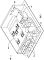
FIG. 3 is a perspective view of a power electronics unit, shown inFIGs. 1 and2 , with a semiconductor portion and an inductor portion; and -
FIG. 4 is a flow diagram illustrating a method of cooling a power electronics unit. - Vapor compression systems (e.g., incorporated within transport refrigeration units) commonly include a compressor, a condenser, an expansion valve, and an evaporator. Refrigerant circulates through the vapor compression system in order to provide cooling to a medium (e.g., the air within the cargo space of the truck/trailer). The refrigerant exits the compressor through a discharge port at a high pressure and a high enthalpy. The refrigerant then flows through the condenser at a high pressure and rejects heat to an external fluid medium (e.g., an air supply or a water supply). The refrigerant then flows through the expansion valve, which expands the refrigerant to a low pressure. After expansion, the refrigerant flows through the evaporator and absorbs heat from another medium (e.g., air). The refrigerant then re-enters the compressor through a suction port, completing the cycle.
- To increase or decrease cooling, the operation (e.g., the speed) of compressor may be adjusted. For example, to increase cooling, the refrigerant may be circulated within the vapor compression system at an increased rate, and conversely, to decrease cooling, the refrigerant may be circulated at a slower rate. To control the operation of the compressor a power electronics unit may be utilized. It should be understood that the power electronics unit may be any electronic device/system that is capable of varying the speed of the compressor. The power electronics unit may include multiple components, each of which may necessitate different amounts of cooling. For example, particular components may produce more heat and thus may require more cooling. In certain instances, at least a portion of the power electronics unit is cooled using at least a portion of the refrigerant from a vapor compression system (e.g., of a transport refrigeration unit). To reduce the impact on the source of the refrigerant, a hybrid cooling system is provided. A hybrid cooling system is a system that incorporates both forced air cooling and liquid cooling.
- With reference now to the Figures, a schematic illustration of a
vapor compression system 100 including acompressor 110, acondenser 150, anevaporator 120, and anexpansion valve 140, with apower electronics unit 130 receiving a working fluid from upstream of theevaporator 120 is shown inFIG. 1 . It should be appreciated that the working fluid may be any fluid capable of transferring heat (e.g., water, refrigerant, brine, etc.). It is envisioned that the driving force of the working fluid through thepower electronics unit 130 may be thecompressor 110 from the vapor compression system 100 (e.g., where no additional compressor or pump is needed separate from the existingcompressor 110 of the vapor compressions system 100). Thecompressor 110 includes an electric drive motor 111 for increasing the pressure of the working fluid. It is envisioned that the electric drive motor 111 may be an AC or DC motor, which may be mounted to thecompressor 110. Theevaporator 120 is in fluid communication with thecompressor 110. Being in fluid communication may be interpreted to mean that theevaporator 120 and thecompressor 110 are included within the same vapor compression system 100 (e.g., where the working fluid that is passed throughevaporator 120 is also passed through the compressor 110). Theevaporator 120 is configured to transfer heat from an external medium (e.g., an air supply or a water supply) to the working fluid. - The
power electronics unit 130 is used to control the transfer of an electrical power (e.g., from an on-board battery within the transport refrigeration unit) to the electric drive motor 111 (e.g., through one or more wired connections). Thepower electronics unit 130 includes asemiconductor portion 132 and aninductor portion 131. Thesemiconductor portion 132 includes at least onefan 133 configured to transfer heat from thesemiconductor portion 132. Theinductor portion 131 includes at least oneconduit 134 configured to receive at least a portion of the working fluid (e.g., from upstream of the evaporator 120). The working fluid is used to transfer heat from theinductor portion 131. - Once used by the
power electronics unit 130 to remove heat from theinductor portion 131, the working fluid may be sent either to the compressor 110 (as shown inFIG. 1 ), or to the evaporator 120 (as shown inFIG. 2 ). In certain instances, the working fluid may be sent from thepower electronics unit 130 to both thecompressor 110 and theevaporator 120. For example, a portion of the working fluid may be sent from thepower electronics unit 130 to thecompressor 110 and a portion of the working fluid may be sent from thepower electronics unit 130 to theevaporator 120. It may be advantageous to send the working fluid from thepower electronics unit 130 to theevaporator 120 when the heat produced by theinductor portion 131 is not sufficiently high enough to utilize the entire cooling capacity of the working fluid. Conversely, it may be advantageous to send the working fluid from thepower electronics unit 130 to thecompressor 110 when the heat produced by theinductor portion 131 is sufficiently high enough to utilize majority of the cooling capacity of the working fluid. - The heat generated by the
power electronics unit 130 may be proportional to the transfer of the electrical power to the electric drive motor 111 of thecompressor 110. For example, thepower electronics unit 130 may generate more heat when more electrical power is transferred to the electric drive motor 111, and may generate less heat when less electrical power is transferred to the electric drive motor 111. Regardless of the amount of heat generated, thepower electronics unit 130 may generate more heat in one portion than another. For example, thesemiconductor portion 132 may generate more heat than theinductor portion 131. In certain instances, at least 60% of the heat generated by thepower electronics unit 130 is derived from thesemiconductor portion 132. In certain instances, less than 40% of the heat generated by thepower electronics unit 130 is derived from theinductor portion 131. To minimize the impact on the vapor compression system (e.g., within the transport refrigeration unit), thesemiconductor portion 132 may be air cooled (e.g., using one or more fan 133). - For example, at least one
fan 133 may be used to transfer substantially all of the heat derived from thesemiconductor portion 132. This may be interpreted to mean that thesemiconductor portion 132 may not be cooled using any of the cooling capacity of the working fluid. Instead of cooling both thesemiconductor portion 132 and theinductor portion 131 with working fluid, thesystem 100 solely uses working fluid to cool theinductor portion 131. In certain instances, the working fluid transfers substantially all of the heat derived from theinductor portion 131. This may be interpreted to mean that the inductor portion may only be cooled using working fluid. However, it should be appreciated that one ormore fan 133 may be used to remove at least a portion of the generated by theinductor portion 131. For example, thefan 133 for thesemiconductor portion 132 may be configured to direct an airflow over both thesemiconductor portion 132 and theinductor portion 131. It is envisioned, however, that theinductor portion 131 may have a separate fan (not shown) dedicated to cooling theinductor portion 131. - By limiting the liquid cooling to only the
inductor portion 131, the impact of thepower electronics unit 130 on thevapor compression system 100 is minimized (e.g., by at least 60% compared to processes utilizing liquid cooling for the entire power electronics unit 130). Instead of using working fluid from thevapor compression system 100 to cool the entirepower electronics unit 130, as has been done in prior applications, thissystem 100 utilizes a hybrid cooling technique to only provide liquid cooling to theinductor portion 131. As mentioned above, theinductor portion 131 is responsible for less than 40% of the heat generated by thepower electronics unit 130, with the remaining amount (e.g., at least 60%) of the heat being attributable to thesemiconductor portion 132, which is cooled using at least onefan 133. - It should be appreciated that the ability to limit liquid cooling to only the
inductor portion 131 may be possible because of the shape of the components (e.g., the shape of the semiconductor portion 132). As shown inFIG. 3 , thesemiconductor portion 132 may be designed to be relatively flat, which may make thesemiconductor portion 132 easier to cool with air (e.g., with one ormore fan 133 disposed near the semiconductor portion 132) than the inductor portion 131 (e.g., which may have a complex three-dimensional structure). To provide liquid cooling to theinductor portion 131 one ormore conduits 134 may be used to circulate working fluid (e.g., refrigerant) either around or through theinductor portion 131. As shown, the working fluid may not flow through theconduits 134 either around or through thesemiconductor portion 132, and as such may not provide any cooling for thesemiconductor portion 132. As described above, this method of cooling may reduce the impact of thepower electronics unit 130 on the source of the working fluid (e.g., the vapor compression system 100). - This method 800 of cooling a
power electronics unit 130 is shown inFIG. 4 . This method 800 may be completed, for example, using the exemplarypower electronics unit 130 shown inFIG. 3 and/or the exemplary vapor compression systems shown inFIGs. 1 and2 . As described above, this method 800 may provide for forced air cooling (e.g., using one or more fan 133) for thesemiconductor portion 132 of thepower electronics unit 130, and liquid cooling (e.g., using one or more conduit 134) for theinductor portion 131 of thepower electronics unit 130. This method 800 includesstep 810 for passing a working fluid through aconduit 134 to theinductor portion 131 of thepower electronics unit 130 to transfer heat from theinductor portion 131. The method 800 also includesstep 820 for operating at least onefan 133 to transfer heat from thesemiconductor portion 132 of thepower electronics unit 130. As described above, this method 800 may reduce the impact of thepower electronics unit 130 on the source of the working fluid by at least 60% relative to processes that utilize liquid cooling for the entirepower electronics unit 130. - The use of the terms "a" and "and" and "the" and similar referents, in the context of describing the invention, are to be construed to cover both the singular and the plural, unless otherwise indicated herein or cleared contradicted by context. The use of any and all example, or exemplary language (e.g., "such as", "e.g.", "for example", etc.) provided herein is intended merely to better illuminate the invention and does not pose a limitation on the scope of the invention unless otherwise claimed. No language in the specification should be construed as indicating any non-claimed elements as essential to the practice of the invention.
- While the present invention has been described with reference to an exemplary embodiment or embodiments, it will be understood by those skilled in the art that various changes may be made and equivalents may be substituted for elements thereof without departing from the scope of the present invention. In addition, many modifications may be made to adapt a particular situation or material to the teachings of the present disclosure without departing from the scope of the invention, as defined by the claims. Therefore, it is intended that the present invention not be limited to the particular embodiment disclosed as the best mode contemplated for carrying out this present invention, but that the present invention will include all embodiments falling within the scope of the claims.
Claims (15)
- A power electronics unit (130) comprising:a semiconductor portion (132) comprising at least one fan (133) configured to transfer heat from the semiconductor portion (132); andan inductor portion (131) comprising at least one conduit (134) configured to receive a working fluid, the working fluid configured to transfer heat from the inductor portion (131).
- The power electronics unit (130) of claim 1, wherein at least 60% of the heat generated by the power electronics unit (130) is derived from the semiconductor portion (132).
- The power electronics unit (130) of claim 1 or 2, wherein less than 40% of the heat generated by the power electronics unit (130) is derived from the inductor portion (131).
- The power electronics unit (130) of claim 1, 2 or 3, wherein the at least one fan (133) transfers substantially all of the heat derived from the semiconductor portion (132).
- The power electronics unit (130) of any of claim 1 to 4, wherein the working fluid transfers substantially all of the heat derived from the inductor portion (131).
- A vapor compression system (100) comprising:a compressor (110) comprising an electric drive motor (111) for increasing the pressure of a working fluid;an evaporator (120) in fluid communication with the compressor (110), the evaporator configured to transfer heat from an external medium to the working fluid; anda power electronics unit (130) as described in any preceding claim for controlling the transfer of an electrical power to the electric drive motor (111), wherein the at least one conduit (134) is configured to receive at least a portion of the working fluid.
- The vapor compression system (100) of claim 6, wherein the inductor portion (131) receives at least a portion of the working fluid from upstream of the evaporator (120).
- The vapor compression system (100) of claim 6 or 7, wherein the working fluid from the inductor portion (131) is transferred to the compressor (110).
- The vapor compression system (100) of claim 6, 7 or 8, wherein the working fluid from the inductor portion (131) is transferred to the evaporator (120).
- The vapor compression system (100) of any of claims 6 to 9, wherein the heat generated by the power electronics unit (130) is proportional to the transfer of the electrical power to the electric drive motor (111).
- The vapor compression system (100) of any of claims 6 to 10, wherein the working fluid is a refrigerant.
- A method (800) of cooling a power electronics unit (130), the power electronics unit comprising a semiconductor portion (132) comprising at least one fan (133), and an inductor portion (131) comprising at least one conduit (134), the method comprising:passing a working fluid through the conduit (134), the working fluid transferring heat from the inductor portion (131); andoperating at least one fan (133) to transfer heat from the semiconductor portion (132).
- The method (800) of cooling a power electronics unit (130) of claim 12, further comprising transferring an electrical power from the power electronics unit (130) to an electric drive motor (111) of a compressor (110), the compressor configured to change the pressure of the working fluid.
- The method (800) of cooling a power electronics unit (130) of claim 13, wherein the heat generated by the power electronics unit (130) is proportional to the transfer of the electrical power to the electric drive motor (111).
- The method (800) of cooling a power electronics unit (130) of claims 12, 13 or 14, wherein at least 60% of the heat generated by the power electronics unit (130) is derived from the semiconductor portion (132), substantially all of the heat derived from the semiconductor is transferred by the at least one fan (133), and/or
wherein less than 40% of the heat generated by the power electronics unit (130) is derived from the inductor portion (131), substantially all of the heat derived from the inductor portion (131) is transferred by the working fluid.
Applications Claiming Priority (1)
| Application Number | Priority Date | Filing Date | Title |
|---|---|---|---|
| US202062704328P | 2020-05-05 | 2020-05-05 |
Publications (2)
| Publication Number | Publication Date |
|---|---|
| EP3908095A1 true EP3908095A1 (en) | 2021-11-10 |
| EP3908095B1 EP3908095B1 (en) | 2024-07-03 |
Family
ID=75690187
Family Applications (1)
| Application Number | Title | Priority Date | Filing Date |
|---|---|---|---|
| EP21170642.9A Active EP3908095B1 (en) | 2020-05-05 | 2021-04-27 | Hybrid cooling for power electronics unit |
Country Status (3)
| Country | Link |
|---|---|
| US (1) | US11464136B2 (en) |
| EP (1) | EP3908095B1 (en) |
| CN (1) | CN113606803A (en) |
Citations (3)
| Publication number | Priority date | Publication date | Assignee | Title |
|---|---|---|---|---|
| US20100085708A1 (en) * | 2008-10-07 | 2010-04-08 | Liebert Corporation | High-efficiency, fluid-cooled ups converter |
| WO2019018681A1 (en) * | 2017-07-19 | 2019-01-24 | Johnson Controls Technology Company | Electronics cooling system |
| US10537046B1 (en) * | 2018-11-30 | 2020-01-14 | Teco-Westinghouse Motor Company | Cooling methods for medium voltage drive systems |
Family Cites Families (14)
| Publication number | Priority date | Publication date | Assignee | Title |
|---|---|---|---|---|
| US4720981A (en) * | 1986-12-23 | 1988-01-26 | American Standard Inc. | Cooling of air conditioning control electronics |
| DK172128B1 (en) * | 1995-07-06 | 1997-11-17 | Danfoss As | Compressor with control electronics |
| JP4200850B2 (en) * | 2003-07-17 | 2008-12-24 | 株式会社デンソー | Electric compressor |
| US9553499B2 (en) * | 2004-06-17 | 2017-01-24 | Edward Handy | Distributed gap inductor potting apparatus and method of use thereof |
| US20090314018A1 (en) * | 2006-06-15 | 2009-12-24 | Carrier Corporation | Compressor power control |
| US8459053B2 (en) * | 2007-10-08 | 2013-06-11 | Emerson Climate Technologies, Inc. | Variable speed compressor protection system and method |
| JP2012223033A (en) * | 2011-04-13 | 2012-11-12 | Yaskawa Electric Corp | Electric power conversion system |
| JP5510750B2 (en) * | 2011-04-18 | 2014-06-04 | 株式会社安川電機 | Power converter and reactor |
| US20150315935A1 (en) * | 2014-04-30 | 2015-11-05 | General Electric Company | System and method for inductor cooling |
| JP6222012B2 (en) * | 2014-08-29 | 2017-11-01 | 株式会社デンソー | Electronic component cooling structure and electric compressor |
| JP6667210B2 (en) | 2015-05-11 | 2020-03-18 | 三菱重工サーマルシステムズ株式会社 | Transport refrigerators and trailers |
| CN109074932B (en) | 2016-03-30 | 2021-07-30 | 住友重机械工业株式会社 | Superconducting magnet device and ultra-low temperature refrigerator system |
| US11252847B2 (en) * | 2017-06-30 | 2022-02-15 | General Electric Company | Heat dissipation system and an associated method thereof |
| CN109842271A (en) * | 2017-11-27 | 2019-06-04 | 中车株洲电力机车研究所有限公司 | A kind of frequency converter that integrated air-conditioning is cooling |
-
2021
- 2021-04-26 US US17/302,161 patent/US11464136B2/en active Active
- 2021-04-27 EP EP21170642.9A patent/EP3908095B1/en active Active
- 2021-04-30 CN CN202110483714.2A patent/CN113606803A/en active Pending
Patent Citations (3)
| Publication number | Priority date | Publication date | Assignee | Title |
|---|---|---|---|---|
| US20100085708A1 (en) * | 2008-10-07 | 2010-04-08 | Liebert Corporation | High-efficiency, fluid-cooled ups converter |
| WO2019018681A1 (en) * | 2017-07-19 | 2019-01-24 | Johnson Controls Technology Company | Electronics cooling system |
| US10537046B1 (en) * | 2018-11-30 | 2020-01-14 | Teco-Westinghouse Motor Company | Cooling methods for medium voltage drive systems |
Also Published As
| Publication number | Publication date |
|---|---|
| US20210352826A1 (en) | 2021-11-11 |
| EP3908095B1 (en) | 2024-07-03 |
| US11464136B2 (en) | 2022-10-04 |
| CN113606803A (en) | 2021-11-05 |
Similar Documents
| Publication | Publication Date | Title |
|---|---|---|
| EP3472541B1 (en) | Mechanical subcooler with battery supplement | |
| EP3472542B1 (en) | Transport refrigeration system with a battery system and corresponding method | |
| EP2795208B1 (en) | Power supply system for transport refrigeration system | |
| EP3750725B1 (en) | Transport refrigeration system and method of operating it | |
| EP3481657B1 (en) | Dual compressor transportation refrigeration unit | |
| EP3472537B1 (en) | Hot gas bypass for battery pack cold start | |
| CN103476613A (en) | Semi-electric mobile refrigeration system | |
| WO2018134634A1 (en) | Transport refrigeration unit comprising a module for energy management | |
| EP3188360B1 (en) | Continuous voltage control of a transport refrigeration system | |
| EP3371527B1 (en) | Transport refrigeration system and method of operating | |
| CN101553699A (en) | Compressor Power Control | |
| US11345210B2 (en) | High voltage auxiliary power unit for a transportation refrigeration system | |
| EP3243032B1 (en) | Vfd control for multiple circuit refrigeration system | |
| US11472266B2 (en) | Engine exhaust gas cooling system for transport refrigeration system | |
| US11464136B2 (en) | Hybrid cooling for power electronics unit | |
| CN108778803B (en) | Return air inlet grille deicing method | |
| CN107076480B (en) | Storage unit and temperature control system for storage unit | |
| EP3452752B1 (en) | Method of improving compressed natural gas tank fill | |
| WO2017156104A1 (en) | Transport refrigeration unit and method of operating |
Legal Events
| Date | Code | Title | Description |
|---|---|---|---|
| PUAI | Public reference made under article 153(3) epc to a published international application that has entered the european phase |
Free format text: ORIGINAL CODE: 0009012 |
|
| STAA | Information on the status of an ep patent application or granted ep patent |
Free format text: STATUS: THE APPLICATION HAS BEEN PUBLISHED |
|
| AK | Designated contracting states |
Kind code of ref document: A1 Designated state(s): AL AT BE BG CH CY CZ DE DK EE ES FI FR GB GR HR HU IE IS IT LI LT LU LV MC MK MT NL NO PL PT RO RS SE SI SK SM TR |
|
| B565 | Issuance of search results under rule 164(2) epc |
Effective date: 20210928 |
|
| STAA | Information on the status of an ep patent application or granted ep patent |
Free format text: STATUS: REQUEST FOR EXAMINATION WAS MADE |
|
| 17P | Request for examination filed |
Effective date: 20220510 |
|
| RBV | Designated contracting states (corrected) |
Designated state(s): AL AT BE BG CH CY CZ DE DK EE ES FI FR GB GR HR HU IE IS IT LI LT LU LV MC MK MT NL NO PL PT RO RS SE SI SK SM TR |
|
| GRAP | Despatch of communication of intention to grant a patent |
Free format text: ORIGINAL CODE: EPIDOSNIGR1 |
|
| STAA | Information on the status of an ep patent application or granted ep patent |
Free format text: STATUS: GRANT OF PATENT IS INTENDED |
|
| INTG | Intention to grant announced |
Effective date: 20240202 |
|
| GRAS | Grant fee paid |
Free format text: ORIGINAL CODE: EPIDOSNIGR3 |
|
| GRAA | (expected) grant |
Free format text: ORIGINAL CODE: 0009210 |
|
| STAA | Information on the status of an ep patent application or granted ep patent |
Free format text: STATUS: THE PATENT HAS BEEN GRANTED |
|
| AK | Designated contracting states |
Kind code of ref document: B1 Designated state(s): AL AT BE BG CH CY CZ DE DK EE ES FI FR GB GR HR HU IE IS IT LI LT LU LV MC MK MT NL NO PL PT RO RS SE SI SK SM TR |
|
| REG | Reference to a national code |
Ref country code: CH Ref legal event code: EP |
|
| REG | Reference to a national code |
Ref country code: DE Ref legal event code: R096 Ref document number: 602021015009 Country of ref document: DE |
|
| REG | Reference to a national code |
Ref country code: NL Ref legal event code: FP |
|
| REG | Reference to a national code |
Ref country code: LT Ref legal event code: MG9D |
|
| PG25 | Lapsed in a contracting state [announced via postgrant information from national office to epo] |
Ref country code: PT Free format text: LAPSE BECAUSE OF FAILURE TO SUBMIT A TRANSLATION OF THE DESCRIPTION OR TO PAY THE FEE WITHIN THE PRESCRIBED TIME-LIMIT Effective date: 20241104 |
|
| REG | Reference to a national code |
Ref country code: AT Ref legal event code: MK05 Ref document number: 1701131 Country of ref document: AT Kind code of ref document: T Effective date: 20240703 |
|
| PG25 | Lapsed in a contracting state [announced via postgrant information from national office to epo] |
Ref country code: PT Free format text: LAPSE BECAUSE OF FAILURE TO SUBMIT A TRANSLATION OF THE DESCRIPTION OR TO PAY THE FEE WITHIN THE PRESCRIBED TIME-LIMIT Effective date: 20241104 |
|
| PG25 | Lapsed in a contracting state [announced via postgrant information from national office to epo] |
Ref country code: NO Free format text: LAPSE BECAUSE OF FAILURE TO SUBMIT A TRANSLATION OF THE DESCRIPTION OR TO PAY THE FEE WITHIN THE PRESCRIBED TIME-LIMIT Effective date: 20241003 |
|
| PG25 | Lapsed in a contracting state [announced via postgrant information from national office to epo] |
Ref country code: FI Free format text: LAPSE BECAUSE OF FAILURE TO SUBMIT A TRANSLATION OF THE DESCRIPTION OR TO PAY THE FEE WITHIN THE PRESCRIBED TIME-LIMIT Effective date: 20240703 Ref country code: GR Free format text: LAPSE BECAUSE OF FAILURE TO SUBMIT A TRANSLATION OF THE DESCRIPTION OR TO PAY THE FEE WITHIN THE PRESCRIBED TIME-LIMIT Effective date: 20241004 Ref country code: PL Free format text: LAPSE BECAUSE OF FAILURE TO SUBMIT A TRANSLATION OF THE DESCRIPTION OR TO PAY THE FEE WITHIN THE PRESCRIBED TIME-LIMIT Effective date: 20240703 |
|
| PG25 | Lapsed in a contracting state [announced via postgrant information from national office to epo] |
Ref country code: BG Free format text: LAPSE BECAUSE OF FAILURE TO SUBMIT A TRANSLATION OF THE DESCRIPTION OR TO PAY THE FEE WITHIN THE PRESCRIBED TIME-LIMIT Effective date: 20240703 |
|
| PG25 | Lapsed in a contracting state [announced via postgrant information from national office to epo] |
Ref country code: LV Free format text: LAPSE BECAUSE OF FAILURE TO SUBMIT A TRANSLATION OF THE DESCRIPTION OR TO PAY THE FEE WITHIN THE PRESCRIBED TIME-LIMIT Effective date: 20240703 |
|
| PG25 | Lapsed in a contracting state [announced via postgrant information from national office to epo] |
Ref country code: AT Free format text: LAPSE BECAUSE OF FAILURE TO SUBMIT A TRANSLATION OF THE DESCRIPTION OR TO PAY THE FEE WITHIN THE PRESCRIBED TIME-LIMIT Effective date: 20240703 Ref country code: IS Free format text: LAPSE BECAUSE OF FAILURE TO SUBMIT A TRANSLATION OF THE DESCRIPTION OR TO PAY THE FEE WITHIN THE PRESCRIBED TIME-LIMIT Effective date: 20241103 |
|
| PG25 | Lapsed in a contracting state [announced via postgrant information from national office to epo] |
Ref country code: HR Free format text: LAPSE BECAUSE OF FAILURE TO SUBMIT A TRANSLATION OF THE DESCRIPTION OR TO PAY THE FEE WITHIN THE PRESCRIBED TIME-LIMIT Effective date: 20240703 Ref country code: CZ Free format text: LAPSE BECAUSE OF FAILURE TO SUBMIT A TRANSLATION OF THE DESCRIPTION OR TO PAY THE FEE WITHIN THE PRESCRIBED TIME-LIMIT Effective date: 20240703 |
|
| PG25 | Lapsed in a contracting state [announced via postgrant information from national office to epo] |
Ref country code: RS Free format text: LAPSE BECAUSE OF FAILURE TO SUBMIT A TRANSLATION OF THE DESCRIPTION OR TO PAY THE FEE WITHIN THE PRESCRIBED TIME-LIMIT Effective date: 20241003 Ref country code: ES Free format text: LAPSE BECAUSE OF FAILURE TO SUBMIT A TRANSLATION OF THE DESCRIPTION OR TO PAY THE FEE WITHIN THE PRESCRIBED TIME-LIMIT Effective date: 20240703 |
|
| PG25 | Lapsed in a contracting state [announced via postgrant information from national office to epo] |
Ref country code: RS Free format text: LAPSE BECAUSE OF FAILURE TO SUBMIT A TRANSLATION OF THE DESCRIPTION OR TO PAY THE FEE WITHIN THE PRESCRIBED TIME-LIMIT Effective date: 20241003 Ref country code: PL Free format text: LAPSE BECAUSE OF FAILURE TO SUBMIT A TRANSLATION OF THE DESCRIPTION OR TO PAY THE FEE WITHIN THE PRESCRIBED TIME-LIMIT Effective date: 20240703 Ref country code: NO Free format text: LAPSE BECAUSE OF FAILURE TO SUBMIT A TRANSLATION OF THE DESCRIPTION OR TO PAY THE FEE WITHIN THE PRESCRIBED TIME-LIMIT Effective date: 20241003 Ref country code: LV Free format text: LAPSE BECAUSE OF FAILURE TO SUBMIT A TRANSLATION OF THE DESCRIPTION OR TO PAY THE FEE WITHIN THE PRESCRIBED TIME-LIMIT Effective date: 20240703 Ref country code: IS Free format text: LAPSE BECAUSE OF FAILURE TO SUBMIT A TRANSLATION OF THE DESCRIPTION OR TO PAY THE FEE WITHIN THE PRESCRIBED TIME-LIMIT Effective date: 20241103 Ref country code: HR Free format text: LAPSE BECAUSE OF FAILURE TO SUBMIT A TRANSLATION OF THE DESCRIPTION OR TO PAY THE FEE WITHIN THE PRESCRIBED TIME-LIMIT Effective date: 20240703 Ref country code: GR Free format text: LAPSE BECAUSE OF FAILURE TO SUBMIT A TRANSLATION OF THE DESCRIPTION OR TO PAY THE FEE WITHIN THE PRESCRIBED TIME-LIMIT Effective date: 20241004 Ref country code: FI Free format text: LAPSE BECAUSE OF FAILURE TO SUBMIT A TRANSLATION OF THE DESCRIPTION OR TO PAY THE FEE WITHIN THE PRESCRIBED TIME-LIMIT Effective date: 20240703 Ref country code: ES Free format text: LAPSE BECAUSE OF FAILURE TO SUBMIT A TRANSLATION OF THE DESCRIPTION OR TO PAY THE FEE WITHIN THE PRESCRIBED TIME-LIMIT Effective date: 20240703 Ref country code: CZ Free format text: LAPSE BECAUSE OF FAILURE TO SUBMIT A TRANSLATION OF THE DESCRIPTION OR TO PAY THE FEE WITHIN THE PRESCRIBED TIME-LIMIT Effective date: 20240703 Ref country code: BG Free format text: LAPSE BECAUSE OF FAILURE TO SUBMIT A TRANSLATION OF THE DESCRIPTION OR TO PAY THE FEE WITHIN THE PRESCRIBED TIME-LIMIT Effective date: 20240703 Ref country code: AT Free format text: LAPSE BECAUSE OF FAILURE TO SUBMIT A TRANSLATION OF THE DESCRIPTION OR TO PAY THE FEE WITHIN THE PRESCRIBED TIME-LIMIT Effective date: 20240703 |
|
| REG | Reference to a national code |
Ref country code: DE Ref legal event code: R097 Ref document number: 602021015009 Country of ref document: DE |
|
| PG25 | Lapsed in a contracting state [announced via postgrant information from national office to epo] |
Ref country code: SM Free format text: LAPSE BECAUSE OF FAILURE TO SUBMIT A TRANSLATION OF THE DESCRIPTION OR TO PAY THE FEE WITHIN THE PRESCRIBED TIME-LIMIT Effective date: 20240703 Ref country code: RO Free format text: LAPSE BECAUSE OF FAILURE TO SUBMIT A TRANSLATION OF THE DESCRIPTION OR TO PAY THE FEE WITHIN THE PRESCRIBED TIME-LIMIT Effective date: 20240703 Ref country code: DK Free format text: LAPSE BECAUSE OF FAILURE TO SUBMIT A TRANSLATION OF THE DESCRIPTION OR TO PAY THE FEE WITHIN THE PRESCRIBED TIME-LIMIT Effective date: 20240703 |
|
| PGFP | Annual fee paid to national office [announced via postgrant information from national office to epo] |
Ref country code: NL Payment date: 20250319 Year of fee payment: 5 |
|
| PG25 | Lapsed in a contracting state [announced via postgrant information from national office to epo] |
Ref country code: EE Free format text: LAPSE BECAUSE OF FAILURE TO SUBMIT A TRANSLATION OF THE DESCRIPTION OR TO PAY THE FEE WITHIN THE PRESCRIBED TIME-LIMIT Effective date: 20240703 |
|
| PG25 | Lapsed in a contracting state [announced via postgrant information from national office to epo] |
Ref country code: IT Free format text: LAPSE BECAUSE OF FAILURE TO SUBMIT A TRANSLATION OF THE DESCRIPTION OR TO PAY THE FEE WITHIN THE PRESCRIBED TIME-LIMIT Effective date: 20240703 Ref country code: SK Free format text: LAPSE BECAUSE OF FAILURE TO SUBMIT A TRANSLATION OF THE DESCRIPTION OR TO PAY THE FEE WITHIN THE PRESCRIBED TIME-LIMIT Effective date: 20240703 |
|
| PLBE | No opposition filed within time limit |
Free format text: ORIGINAL CODE: 0009261 |
|
| STAA | Information on the status of an ep patent application or granted ep patent |
Free format text: STATUS: NO OPPOSITION FILED WITHIN TIME LIMIT |
|
| 26N | No opposition filed |
Effective date: 20250404 |
|
| PGFP | Annual fee paid to national office [announced via postgrant information from national office to epo] |
Ref country code: DE Payment date: 20250319 Year of fee payment: 5 |
|
| PG25 | Lapsed in a contracting state [announced via postgrant information from national office to epo] |
Ref country code: SE Free format text: LAPSE BECAUSE OF FAILURE TO SUBMIT A TRANSLATION OF THE DESCRIPTION OR TO PAY THE FEE WITHIN THE PRESCRIBED TIME-LIMIT Effective date: 20240703 |
|
| REG | Reference to a national code |
Ref country code: CH Ref legal event code: H13 Free format text: ST27 STATUS EVENT CODE: U-0-0-H10-H13 (AS PROVIDED BY THE NATIONAL OFFICE) Effective date: 20251125 |
|
| PG25 | Lapsed in a contracting state [announced via postgrant information from national office to epo] |
Ref country code: LU Free format text: LAPSE BECAUSE OF NON-PAYMENT OF DUE FEES Effective date: 20250427 |
|
| PG25 | Lapsed in a contracting state [announced via postgrant information from national office to epo] |
Ref country code: MC Free format text: LAPSE BECAUSE OF FAILURE TO SUBMIT A TRANSLATION OF THE DESCRIPTION OR TO PAY THE FEE WITHIN THE PRESCRIBED TIME-LIMIT Effective date: 20240703 |
|
| REG | Reference to a national code |
Ref country code: BE Ref legal event code: MM Effective date: 20250430 |
|
| PG25 | Lapsed in a contracting state [announced via postgrant information from national office to epo] |
Ref country code: BE Free format text: LAPSE BECAUSE OF NON-PAYMENT OF DUE FEES Effective date: 20250430 |
|
| PG25 | Lapsed in a contracting state [announced via postgrant information from national office to epo] |
Ref country code: CH Free format text: LAPSE BECAUSE OF NON-PAYMENT OF DUE FEES Effective date: 20250430 |
|
| PGFP | Annual fee paid to national office [announced via postgrant information from national office to epo] |
Ref country code: GB Payment date: 20260319 Year of fee payment: 6 |
|
| PG25 | Lapsed in a contracting state [announced via postgrant information from national office to epo] |
Ref country code: IE Free format text: LAPSE BECAUSE OF NON-PAYMENT OF DUE FEES Effective date: 20250427 |
|
| PGFP | Annual fee paid to national office [announced via postgrant information from national office to epo] |
Ref country code: FR Payment date: 20260320 Year of fee payment: 6 |