EP3907875B1 - Power conversion apparatus, and method for determining a working status of the power conversion apparatus - Google Patents
Power conversion apparatus, and method for determining a working status of the power conversion apparatus Download PDFInfo
- Publication number
- EP3907875B1 EP3907875B1 EP19916978.0A EP19916978A EP3907875B1 EP 3907875 B1 EP3907875 B1 EP 3907875B1 EP 19916978 A EP19916978 A EP 19916978A EP 3907875 B1 EP3907875 B1 EP 3907875B1
- Authority
- EP
- European Patent Office
- Prior art keywords
- power conversion
- state
- conversion apparatus
- impedance
- circuit
- Prior art date
- Legal status (The legal status is an assumption and is not a legal conclusion. Google has not performed a legal analysis and makes no representation as to the accuracy of the status listed.)
- Active
Links
Images


Classifications
-
- H—ELECTRICITY
- H02—GENERATION; CONVERSION OR DISTRIBUTION OF ELECTRIC POWER
- H02J—ELECTRIC POWER NETWORKS; CIRCUIT ARRANGEMENTS OR SYSTEMS FOR SUPPLYING OR DISTRIBUTING ELECTRIC POWER; SYSTEMS FOR STORING ELECTRIC ENERGY
- H02J3/00—Circuit arrangements for AC mains or AC distribution networks
- H02J3/38—Arrangements for feeding a single network from two or more generators or sources in parallel; Arrangements for feeding already energised networks from additional generators or sources in parallel
-
- H—ELECTRICITY
- H02—GENERATION; CONVERSION OR DISTRIBUTION OF ELECTRIC POWER
- H02M—APPARATUS FOR CONVERSION BETWEEN AC AND AC, BETWEEN AC AND DC, OR BETWEEN DC AND DC, AND FOR USE WITH MAINS OR SIMILAR POWER SUPPLY SYSTEMS; CONVERSION OF DC OR AC INPUT POWER INTO SURGE OUTPUT POWER; CONTROL OR REGULATION THEREOF
- H02M1/00—Details of apparatus for conversion
- H02M1/36—Means for starting or stopping converters
-
- H—ELECTRICITY
- H02—GENERATION; CONVERSION OR DISTRIBUTION OF ELECTRIC POWER
- H02M—APPARATUS FOR CONVERSION BETWEEN AC AND AC, BETWEEN AC AND DC, OR BETWEEN DC AND DC, AND FOR USE WITH MAINS OR SIMILAR POWER SUPPLY SYSTEMS; CONVERSION OF DC OR AC INPUT POWER INTO SURGE OUTPUT POWER; CONTROL OR REGULATION THEREOF
- H02M7/00—Conversion of AC power input into DC power output; Conversion of DC power input into AC power output
- H02M7/42—Conversion of DC power input into AC power output without possibility of reversal
- H02M7/44—Conversion of DC power input into AC power output without possibility of reversal by static converters
- H02M7/48—Conversion of DC power input into AC power output without possibility of reversal by static converters using discharge tubes with control electrode or semiconductor devices with control electrode
-
- H—ELECTRICITY
- H02—GENERATION; CONVERSION OR DISTRIBUTION OF ELECTRIC POWER
- H02S—GENERATION OF ELECTRIC POWER BY CONVERSION OF INFRARED RADIATION, VISIBLE LIGHT OR ULTRAVIOLET LIGHT, e.g. USING PHOTOVOLTAIC [PV] MODULES
- H02S40/00—Components or accessories in combination with PV modules, not provided for in groups H02S10/00 - H02S30/00
- H02S40/30—Electrical components
- H02S40/32—Electrical components comprising DC/AC inverter means associated with the PV module itself, e.g. AC modules
-
- G—PHYSICS
- G01—MEASURING; TESTING
- G01R—MEASURING ELECTRIC VARIABLES; MEASURING MAGNETIC VARIABLES
- G01R31/00—Arrangements for testing electric properties; Arrangements for locating electric faults; Arrangements for electrical testing characterised by what is being tested not provided for elsewhere
- G01R31/50—Testing of electric apparatus, lines, cables or components for short-circuits, continuity, leakage current or incorrect line connections
- G01R31/66—Testing of connections, e.g. of plugs or non-disconnectable joints
- G01R31/67—Testing the correctness of wire connections in electric apparatus or circuits
-
- G—PHYSICS
- G05—CONTROLLING; REGULATING
- G05F—SYSTEMS FOR REGULATING ELECTRIC OR MAGNETIC VARIABLES
- G05F1/00—Automatic systems in which deviations of an electric quantity from one or more predetermined values are detected at the output of the system and fed back to a device within the system to restore the detected quantity to its predetermined value or values, i.e. retroactive systems
- G05F1/66—Regulating electric power
- G05F1/67—Regulating electric power to the maximum power available from a generator, e.g. from solar cell
-
- H—ELECTRICITY
- H02—GENERATION; CONVERSION OR DISTRIBUTION OF ELECTRIC POWER
- H02M—APPARATUS FOR CONVERSION BETWEEN AC AND AC, BETWEEN AC AND DC, OR BETWEEN DC AND DC, AND FOR USE WITH MAINS OR SIMILAR POWER SUPPLY SYSTEMS; CONVERSION OF DC OR AC INPUT POWER INTO SURGE OUTPUT POWER; CONTROL OR REGULATION THEREOF
- H02M3/00—Conversion of DC power input into DC power output
- H02M3/02—Conversion of DC power input into DC power output without intermediate conversion into AC
- H02M3/04—Conversion of DC power input into DC power output without intermediate conversion into AC by static converters
- H02M3/10—Conversion of DC power input into DC power output without intermediate conversion into AC by static converters using discharge tubes with control electrode or semiconductor devices with control electrode
- H02M3/145—Conversion of DC power input into DC power output without intermediate conversion into AC by static converters using discharge tubes with control electrode or semiconductor devices with control electrode using devices of a triode or transistor type requiring continuous application of a control signal
- H02M3/155—Conversion of DC power input into DC power output without intermediate conversion into AC by static converters using discharge tubes with control electrode or semiconductor devices with control electrode using devices of a triode or transistor type requiring continuous application of a control signal using semiconductor devices only
- H02M3/156—Conversion of DC power input into DC power output without intermediate conversion into AC by static converters using discharge tubes with control electrode or semiconductor devices with control electrode using devices of a triode or transistor type requiring continuous application of a control signal using semiconductor devices only with automatic control of output voltage or current, e.g. switching regulators
- H02M3/158—Conversion of DC power input into DC power output without intermediate conversion into AC by static converters using discharge tubes with control electrode or semiconductor devices with control electrode using devices of a triode or transistor type requiring continuous application of a control signal using semiconductor devices only with automatic control of output voltage or current, e.g. switching regulators including plural semiconductor devices as final control devices for a single load
-
- H—ELECTRICITY
- H02—GENERATION; CONVERSION OR DISTRIBUTION OF ELECTRIC POWER
- H02M—APPARATUS FOR CONVERSION BETWEEN AC AND AC, BETWEEN AC AND DC, OR BETWEEN DC AND DC, AND FOR USE WITH MAINS OR SIMILAR POWER SUPPLY SYSTEMS; CONVERSION OF DC OR AC INPUT POWER INTO SURGE OUTPUT POWER; CONTROL OR REGULATION THEREOF
- H02M3/00—Conversion of DC power input into DC power output
- H02M3/02—Conversion of DC power input into DC power output without intermediate conversion into AC
- H02M3/04—Conversion of DC power input into DC power output without intermediate conversion into AC by static converters
- H02M3/10—Conversion of DC power input into DC power output without intermediate conversion into AC by static converters using discharge tubes with control electrode or semiconductor devices with control electrode
- H02M3/145—Conversion of DC power input into DC power output without intermediate conversion into AC by static converters using discharge tubes with control electrode or semiconductor devices with control electrode using devices of a triode or transistor type requiring continuous application of a control signal
- H02M3/155—Conversion of DC power input into DC power output without intermediate conversion into AC by static converters using discharge tubes with control electrode or semiconductor devices with control electrode using devices of a triode or transistor type requiring continuous application of a control signal using semiconductor devices only
- H02M3/156—Conversion of DC power input into DC power output without intermediate conversion into AC by static converters using discharge tubes with control electrode or semiconductor devices with control electrode using devices of a triode or transistor type requiring continuous application of a control signal using semiconductor devices only with automatic control of output voltage or current, e.g. switching regulators
- H02M3/158—Conversion of DC power input into DC power output without intermediate conversion into AC by static converters using discharge tubes with control electrode or semiconductor devices with control electrode using devices of a triode or transistor type requiring continuous application of a control signal using semiconductor devices only with automatic control of output voltage or current, e.g. switching regulators including plural semiconductor devices as final control devices for a single load
- H02M3/1582—Buck-boost converters
-
- H—ELECTRICITY
- H02—GENERATION; CONVERSION OR DISTRIBUTION OF ELECTRIC POWER
- H02S—GENERATION OF ELECTRIC POWER BY CONVERSION OF INFRARED RADIATION, VISIBLE LIGHT OR ULTRAVIOLET LIGHT, e.g. USING PHOTOVOLTAIC [PV] MODULES
- H02S50/00—Monitoring or testing of PV systems, e.g. load balancing or fault identification
- H02S50/10—Testing of PV devices, e.g. of PV modules or single PV cells
-
- Y—GENERAL TAGGING OF NEW TECHNOLOGICAL DEVELOPMENTS; GENERAL TAGGING OF CROSS-SECTIONAL TECHNOLOGIES SPANNING OVER SEVERAL SECTIONS OF THE IPC; TECHNICAL SUBJECTS COVERED BY FORMER USPC CROSS-REFERENCE ART COLLECTIONS [XRACs] AND DIGESTS
- Y02—TECHNOLOGIES OR APPLICATIONS FOR MITIGATION OR ADAPTATION AGAINST CLIMATE CHANGE
- Y02E—REDUCTION OF GREENHOUSE GAS [GHG] EMISSIONS, RELATED TO ENERGY GENERATION, TRANSMISSION OR DISTRIBUTION
- Y02E10/00—Energy generation through renewable energy sources
- Y02E10/50—Photovoltaic [PV] energy
-
- Y—GENERAL TAGGING OF NEW TECHNOLOGICAL DEVELOPMENTS; GENERAL TAGGING OF CROSS-SECTIONAL TECHNOLOGIES SPANNING OVER SEVERAL SECTIONS OF THE IPC; TECHNICAL SUBJECTS COVERED BY FORMER USPC CROSS-REFERENCE ART COLLECTIONS [XRACs] AND DIGESTS
- Y02—TECHNOLOGIES OR APPLICATIONS FOR MITIGATION OR ADAPTATION AGAINST CLIMATE CHANGE
- Y02E—REDUCTION OF GREENHOUSE GAS [GHG] EMISSIONS, RELATED TO ENERGY GENERATION, TRANSMISSION OR DISTRIBUTION
- Y02E10/00—Energy generation through renewable energy sources
- Y02E10/50—Photovoltaic [PV] energy
- Y02E10/56—Power conversion systems, e.g. maximum power point trackers
Definitions
- This disclosure relates to the field of power converter technologies, and the invention relates in particular to a power conversion apparatus and a method for controlling an output impedance of a power conversion apparatus.
- a photovoltaic power system generally includes photovoltaic modules, optimizers, and an inverter.
- An input end of the optimizer is connected to an output end of the photovoltaic module, and the optimizer is configured to implement maximum power tracking of the photovoltaic module or rapid power-off.
- Output ends of a plurality of optimizers are connected in series and then connected to a direct current input end of the inverter, so that output power of the optimizers in series can be adjusted.
- An alternating current output end of the inverter is connected to a power grid for grid-connected power generation.
- a photovoltaic power system includes optimizers
- the optimizers are usually installed on rear faces of photovoltaic modules (for example, fastened on supports of the photovoltaic modules or frames of the photovoltaic modules).
- the optimizers in series can normally work needs to be determined after the photovoltaic modules in series and the optimizers in series are installed.
- normal installation can be ensured after installation and construction of the photovoltaic modules and the optimizers are completed, and checking of related wiring required due to an optimizer installation problem does not need to be subsequently performed. This avoids complex and strenuous construction operations required for checking optimizer-related wiring.
- a photovoltaic power system is installed on a roof
- a photovoltaic module is usually installed close to the roof and an optimizer is usually installed between a PV panel and the roof
- the photovoltaic module needs to be disassembled for wiring check. In this case, it is difficult to perform a construction operation.
- the following method is used to determine whether an installed optimizer can normally work: After a single optimizer is connected to a photovoltaic module and is powered on, an output voltage is controlled to be 1 V, and whether the optimizer normally works can be determined by testing whether the output voltage of the optimizer is 1 V. After installation of photovoltaic modules in series and optimizers in series is completed, the optimizers are powered on, and an output voltage of each of the optimizers is controlled to be 1 V. A quantity of connected optimizers is determined by testing an output voltage of the optimizers in series. For example, if the measured output voltage of the optimizers in series is 20 V, it can be determined that 20 optimizers normally work.
- the output voltage of the optimizer is relatively low (1 V), and it is quite difficult to ensure actual control precision.
- the output voltage of the optimizer is relatively low (1 V), and it is quite difficult to ensure actual control precision.
- EP 2 444 872 A2 discloses a switching power supply of a photovoltaic system. It comprises two stages between an input and an output of the switching power supply. The two stages are coupled by an intermediate circuit consisting of a transistor and a resistor. With this intermediate circuit, the second stage is initiated when sufficient power is supplied by the photovoltaic elements.
- US 5,179,488 relates to a process control instrument with aloop overcurrent circuit.
- CN 104 079 001 B relates to an optimizer control method based on series-type optimizers in a photovoltaic grid-connected system.
- the method comprises the following steps: an input voltage of one optimizer is detected; B, whether a photovoltaic module connected with the previous optimizer works or not is judged, wherein if not, the step A is executed, and if yes, the next step C is executed; C, maximum power point tracing is conducted on the photovoltaic module; D, an output voltage of the optimizer is detected; E, whether the output voltage of the optimizer is larger than an upper limit voltage of an output voltage threshold or not is judged, wherein if not, the step C is executed, and if yes, the next step F is executed; F, the optimizer is stopped for a period of time; G whether the output voltage of the optimizer is smaller than a lower limit voltage of the output voltage threshold or not is judged, wherein if not, the step F is executed, and if yes, the next step C is executed.
- the object of the present invention is to provide a power conversion apparatus and a method for controlling an output impedance of a power conversion apparatus, to resolve a prior-art problem of relatively low accuracy of a method for determining a working status of a power conversion apparatus.
- the present invention provides a power conversion apparatus.
- the power conversion apparatus includes a power conversion circuit, an impedance adjustable circuit, and a control circuit.
- the control circuit is connected to both the power conversion circuit and the impedance adjustable circuit, an input end of the power conversion circuit is configured to connect to a power source, and an output end of the power conversion circuit is connected to the impedance adjustable circuit.
- the power conversion circuit is configured to adjust output power of the power conversion circuit under the control of the control circuit.
- the impedance adjustable circuit is configured to adjust an output impedance of the impedance adjustable circuit under the control of the control circuit.
- the control circuit is configured to: when the power conversion apparatus is faulty, control the impedance adjustable circuit to adjust the impedance of the impedance adjustable circuit to a first impedance, or when the power conversion apparatus is normal, control the impedance adjustable circuit to adjust the impedance of the impedance adjustable circuit to a second impedance, where the first impedance is not equal to the second impedance.
- the output impedance of the impedance adjustable circuit is the first impedance when the power conversion apparatus is faulty, or the output impedance of the impedance adjustable circuit is the second impedance when the power conversion apparatus is normal, so that an output impedance of the power conversion apparatus when the power conversion apparatus is faulty is different from an output impedance of the power conversion apparatus when the power conversion apparatus is normal.
- a working status of the power conversion apparatus can be represented by the output impedance of the power conversion apparatus, and the determined working status of the power conversion apparatus is more accurate than a working status of the power conversion apparatus determined in a voltage detection manner in the prior art.
- the power conversion apparatus is an optimizer.
- the impedance adjustable circuit is connected in series to the power conversion circuit, the impedance adjustable circuit includes a first switch and a first load circuit, the first switch is connected in parallel to the first load circuit, and the first switch is further connected to the control circuit.
- the control circuit controls the first switch to be in a first state; or when the power conversion apparatus is normal, the control circuit controls the first switch to be in a second state, where the second state is a state different from the first state.
- the first state is an off state, and the second state is an on state or switching between an off state and an on state according to a specified law; or the first state is an on state, and the second state is an off state or switching between an off state and an on state according to a specified law.
- the first switch when the power conversion apparatus is faulty, the first switch is in an on state, and in this case, the first impedance is zero; or when the power conversion apparatus is normal, the first switch is in an off state, and the second impedance is an impedance of the first load circuit.
- the output impedance of the power conversion apparatus when the output impedance of the power conversion apparatus is an output impedance of the power conversion circuit, it can be represented that the status of the power conversion apparatus is that the power conversion apparatus is normal, or that the power conversion apparatus satisfies a start condition but the power conversion apparatus is faulty.
- the output impedance of the power conversion apparatus is an impedance obtained after an output impedance of the power conversion circuit and the impedance of the first load circuit are connected in series, it can be represented that the status of the power conversion apparatus is that the power conversion apparatus satisfies the start condition and the power conversion apparatus is normal.
- the first switch when the power conversion apparatus is faulty, the first switch is in an off state, and in this case, the first impedance is an impedance of the first load circuit; or when the power conversion apparatus is normal, the first switch is in an on state, and the second impedance is zero.
- the output impedance of the power conversion apparatus when the output impedance of the power conversion apparatus is an impedance obtained after an output impedance of the power conversion circuit and the impedance of the first load circuit are connected in series, it can be represented that the status of the power conversion apparatus is that the power conversion apparatus is faulty, or that the power conversion apparatus satisfies a start condition but the power conversion apparatus is faulty.
- the output impedance of the power conversion apparatus is an output impedance of the power conversion circuit, it can be represented that the status of the power conversion apparatus is that the power conversion apparatus satisfies the start condition and the power conversion apparatus is normal.
- the control circuit when the power conversion apparatus satisfies a start condition, after the control circuit controls the first switch to be in the second state, the control circuit is further configured to: receive first instruction information, and control, according to the first instruction information, the first switch to be in a third state, where the third state is a state different from the second state, so that an output impedance of the power conversion apparatus when the power conversion apparatus normally works is different from the output impedance of the power conversion apparatus when the power conversion apparatus satisfies the start condition; or when the power conversion apparatus satisfies the start condition, after the control circuit controls the first switch to be in the second state, the control circuit is further configured to: determine whether a voltage, a current, or power of an output end of the power conversion apparatus changes; and when determining that the voltage, the current, or the power of the output end of the power conversion apparatus changes, control the first switch to be in a third state, where the third state is a state different from the second state, so that an output impedance of the power conversion apparatus when
- the impedance adjustable circuit is connected in parallel to the power conversion circuit, the impedance adjustable circuit includes a second switch and a second load circuit, the second switch is connected in series to the second load circuit, and the second switch is further connected to the control circuit.
- the control circuit controls the second switch to be in a first state; or when the power conversion apparatus satisfies the start condition, the control circuit controls the second switch to be in a second state, where the second state is a state different from the first state.
- first state is an off state, and the second state is an on state; or the first state is an on state, and the second state is an off state.
- the second switch when the power conversion apparatus does not satisfy the start condition, the second switch is in an on state, and the first impedance is an output impedance of the second load circuit; or when the power conversion apparatus satisfies the start condition, the second switch is in an off state, and the second impedance is infinitely large.
- the output impedance of the power conversion apparatus when the output impedance of the power conversion apparatus is an impedance obtained after an output impedance of the power conversion circuit and the output impedance of the second load circuit are connected in parallel, it can be represented that the status of the power conversion apparatus is that the power conversion apparatus does not satisfy the start condition, or that the power conversion apparatus satisfies the start condition but the power conversion apparatus is faulty.
- the output impedance of the power conversion apparatus is an output impedance of the power conversion circuit
- the status of the power conversion apparatus is that the power conversion apparatus satisfies the start condition and the power conversion apparatus is normal.
- the second switch when the power conversion apparatus does not satisfy the start condition, the second switch is in an off state, and the first impedance is infinitely large; or when the power conversion apparatus satisfies the start condition, the second switch is in an on state, and the second impedance is an output impedance of the second load circuit.
- the output impedance of the power conversion apparatus when the output impedance of the power conversion apparatus is an output impedance of the power conversion circuit, it can be represented that the status of the power conversion apparatus is that the power conversion apparatus does not satisfy the start condition, or that the power conversion apparatus satisfies the start condition but the power conversion apparatus is faulty.
- the output impedance of the power conversion apparatus is an impedance obtained after an output impedance of the power conversion circuit and the output impedance of the second load circuit are connected in parallel, it can be represented that the status of the power conversion apparatus is that the power conversion apparatus satisfies the start condition and the power conversion apparatus is normal.
- the control circuit when the power conversion apparatus satisfies the start condition, after the control circuit controls the second switch to be in the second state, the control circuit is further configured to: receive first instruction information, and control, according to the first instruction information, the second switch to be in a third state, where the third state is a state different from the second state; or when the power conversion apparatus satisfies the start condition, after the control circuit controls the second switch to be in the second state, the control circuit is further configured to: determine whether a voltage, a current, or power of an output end of the power conversion apparatus changes; and when determining that the voltage, the current, or the power of the output end of the power conversion apparatus changes, control the second switch to be in a third state, where the third state is a state different from the second state.
- the impedance adjustable circuit includes a first impedance adjustable circuit and a second impedance adjustable circuit, a first end of the first impedance adjustable circuit is connected, according to the invention, in series to a first output end of the power conversion circuit, and the second impedance adjustable circuit is connected in parallel between a second end of the first impedance adjustable circuit and a second output end of the power conversion circuit, or the second impedance adjustable circuit is connected in parallel to the power conversion circuit, and the first impedance adjustable circuit is connected in series to the second impedance adjustable circuit, where the first impedance adjustable circuit includes a first switch and a first load circuit, the first switch is connected in parallel to the first load circuit, the second impedance adjustable circuit includes a second switch and a second load circuit, the second switch is connected in series to the second load circuit, and the first switch and the second switch are further connected to the control circuit.
- the control circuit controls the first switch to be in a first state, and controls the second switch to be in a first state or a second state, where the second state is a state different from the first state; or when the power conversion apparatus satisfies the start condition, the control circuit controls at least one of the first switch and the second switch to be in a state that is different from a state corresponding to the at least one switch when the power conversion apparatus does not satisfy the start condition.
- the first state is an off state
- the second state is an on state
- a state different from the first state is an on state
- a state different from the second state is an off state
- the control circuit when the power conversion apparatus satisfies the start condition, after the control circuit controls the at least one of the first switch and the second switch to be in the state that is different from the state corresponding to the at least one switch when the power conversion apparatus does not satisfy the start condition, the control circuit is further configured to: receive first instruction information, and control, according to the first instruction information, at least one of the first switch and the second switch to be in a state that is different from a state corresponding to the at least one switch when the power conversion apparatus satisfies the start condition; or when the power conversion apparatus satisfies the start condition, after the control circuit controls the at least one of the first switch and the second switch to be in the state that is different from the state corresponding to the at least one switch when the power conversion apparatus does not satisfy the start condition, the control circuit is further configured to: determine whether a voltage, a current, or power of an output end of the power conversion apparatus changes; and when determining that the voltage, the current, or the power of the output end of the power conversion apparatus changes
- the control circuit when the power conversion apparatus satisfies the start condition, before the control circuit controls the impedance adjustable circuit to adjust the impedance of the impedance adjustable circuit to the second impedance, the control circuit is further configured to determine that the power conversion apparatus can normally work.
- the invention further provides a method for controlling an output impedance of a power conversion apparatus.
- the method includes: adjusting the output impedance of the power conversion apparatus to a first impedance when the power conversion apparatus is faulty; or adjusting the output impedance of the power conversion apparatus to a second impedance when the power conversion apparatus is normal, where the first impedance is not equal to the second impedance.
- the output impedance of the power conversion apparatus is adjusted to the first impedance when the power conversion apparatus is faulty, or the output impedance of the power conversion apparatus is adjusted to the second impedance when the power conversion apparatus is normal, so that the output impedance of the power conversion apparatus when the power conversion apparatus is faulty is different from the output impedance of the power conversion apparatus when the power conversion apparatus is normal.
- a working status of the power conversion apparatus can be represented by the output impedance of the power conversion apparatus, and the determined working status of the power conversion apparatus is more accurate than a working status of the power conversion apparatus determined in a voltage detection manner in the prior art.
- the output impedance of the power conversion apparatus when the output impedance of the power conversion apparatus is the first impedance, it can be represented that the status of the power conversion apparatus is that the power conversion apparatus is faulty, or that the power conversion apparatus satisfies a start condition but the power conversion apparatus is faulty.
- the output impedance of the power conversion apparatus is the second impedance, it can be represented that the status of the power conversion apparatus is that the power conversion apparatus satisfies the start condition and the power conversion apparatus is normal.
- the power conversion apparatus includes a power conversion circuit, an impedance adjustable circuit, and a control circuit.
- the control circuit is connected to both the power conversion circuit and the impedance adjustable circuit, and an output end of the power conversion circuit is connected to the impedance adjustable circuit.
- the adjusting the output impedance of the power conversion apparatus to a first impedance when the power conversion apparatus does not satisfy a start condition includes: adjusting an impedance of the impedance adjustable circuit to a third impedance when the power conversion apparatus does not satisfy the start condition, where the third impedance is determined based on an equivalent impedance of the power conversion circuit when the power conversion circuit does not satisfy the start condition and the first impedance.
- the adjusting the output impedance of the power conversion apparatus to a second impedance when the power conversion apparatus satisfies a start condition includes: adjusting an impedance of the impedance adjustable circuit to a fourth impedance when the power conversion apparatus satisfies the start condition, where the fourth impedance is determined based on an equivalent impedance of the power conversion circuit when the power conversion circuit satisfies the start condition and the second impedance.
- this application further provides a not claimed photovoltaic power system.
- the system includes a photovoltaic module, an optimizer, and an inverter.
- the photovoltaic module is configured to: convert solar energy into electrical energy, and output the electrical energy to the optimizer.
- the optimizer is configured to: adjust an output impedance of the optimizer to a first impedance when the optimizer does not satisfy a start condition, or adjust an output impedance of the optimizer to a second impedance when the optimizer satisfies a start condition, where the first impedance is not equal to the second impedance; and when the optimizer satisfies the start condition and the optimizer needs to control output power, adjust output power of the photovoltaic module and output adjusted power.
- the inverter is configured to: convert the power output by the optimizer into electrical energy satisfying a specified condition, and output the converted electrical energy to a power grid or a load.
- the optimizer includes a power conversion circuit, an impedance adjustable circuit, and a control circuit.
- the control circuit is connected to both the power conversion circuit and the impedance adjustable circuit, and an output end of the power conversion circuit is connected to the impedance adjustable circuit.
- the optimizer is specifically configured to: adjust an impedance of the impedance adjustable circuit to a third impedance when the optimizer does not satisfy the start condition, where the third impedance is determined based on an equivalent impedance of the power conversion circuit when the power conversion circuit does not satisfy the start condition and the first impedance; or adjust an impedance of the impedance adjustable circuit to a fourth impedance when the optimizer satisfies the start condition, where the fourth impedance is determined based on an equivalent impedance of the power conversion circuit when the power conversion circuit satisfies the start condition and the second impedance.
- a photovoltaic power system includes optimizers
- the optimizers are usually installed on rear faces of photovoltaic modules (for example, fastened on supports of the photovoltaic modules or frames of the photovoltaic modules). Therefore, in an installation process of the photovoltaic system, whether the optimizers can normally work needs to be determined after the photovoltaic modules and the optimizers are installed. In this way, normal installation can be ensured after installation and construction of the photovoltaic modules and the optimizers are completed, and checking of related wiring required due to an optimizer installation problem does not need to be subsequently performed. This avoids complex and strenuous construction operations required for checking optimizer-related wiring.
- this application provides a power conversion apparatus and a method for controlling an output impedance of a power conversion apparatus.
- An output impedance of the power conversion apparatus when no signal is input and an output impedance of the power conversion apparatus when a signal is input but no signal is output are set, to make corresponding output impedances of the power conversion apparatus different when the power conversion apparatus is in different working statuses (for example, the power conversion apparatus is faulty or there is no input to the power conversion apparatus).
- the working status of the power conversion apparatus can be represented by the output impedance of the power conversion apparatus.
- the power conversion apparatus 200 includes a power conversion circuit 210, an impedance adjustable circuit 220, and a control circuit 230.
- the control circuit 230 is connected to both the power conversion circuit 210 and the impedance adjustable circuit 220, an input end of the power conversion circuit 210 is configured to connect to a power source, and an output end of the power conversion circuit 210 is connected to the impedance adjustable circuit 220.
- the power conversion circuit 210 is configured to adjust output power of the power conversion circuit 210 under the control of the control circuit 230.
- the impedance adjustable circuit 220 is configured to adjust an output impedance of the impedance adjustable circuit 220 under the control of the control circuit 230.
- the control circuit 230 is configured to: when the power conversion apparatus 200 does not satisfy a start condition, control the impedance adjustable circuit 220 to adjust the impedance of the impedance adjustable circuit 220 to a first impedance, or when the power conversion apparatus 200 satisfies a start condition, control the impedance adjustable circuit 220 to adjust the impedance of the impedance adjustable circuit 220 to a second impedance, where the first impedance is not equal to the second impedance.
- the power conversion apparatus 200 may be an optimizer, and the start condition of the power conversion apparatus 200 is that input power of the power conversion apparatus 200 is greater than or equal to minimum power-on operating power of the control circuit 230.
- the impedance adjustable circuit may be implemented in a manner shown in FIG. 3 .
- the impedance adjustable circuit 220 is connected in series to the power conversion circuit 210, the impedance adjustable circuit 220 includes a first switch K1 and a first load circuit 221, the first switch K1 is connected in parallel to the first load circuit 221, and the first switch K1 is further connected to the control circuit 230.
- the control circuit 230 controls the first switch K1 to be in a first state; or when the power conversion apparatus 200 satisfies the start condition, the control circuit 230 controls the first switch K1 to be in a second state, where the second state is a state different from the first state.
- the first state may be an off state, and in this case, the second state may be an on state or switching between an off state and an on state according to a specified law; or the first state may be an on state, and in this case, the second state is an off state or switching between an off state and an on state according to a specified law.
- the first switch K1 when the power conversion apparatus 200 does not satisfy the start condition, the first switch K1 is in an on state, and in this case, the first impedance is zero; or when the power conversion apparatus 200 satisfies the start condition, the first switch K1 is in an off state, and the second impedance is an impedance of the first load circuit 221.
- an output impedance of the power conversion apparatus 200 when an output impedance of the power conversion apparatus 200 is an output impedance of the power conversion circuit 210, it can be represented that a status of the power conversion apparatus 200 is that the power conversion apparatus 200 does not satisfy the start condition, or that the power conversion apparatus 200 satisfies the start condition but the power conversion apparatus 200 is faulty.
- an output impedance of the power conversion apparatus 200 is an impedance obtained after an output impedance of the power conversion circuit 210 and the impedance of the first load circuit 221 are connected in series, it can be represented that the power conversion apparatus 200 satisfies the start condition and that the power conversion apparatus 200 is normal.
- the first switch K1 when the power conversion apparatus 200 does not satisfy the start condition, the first switch K1 is in an off state, and in this case, the first impedance is an impedance of the first load circuit 221; or when the power conversion apparatus 200 satisfies the start condition, the first switch K1 is in an on state, and the second impedance is zero.
- an output impedance of the power conversion apparatus 200 is an impedance obtained after an output impedance of the power conversion circuit 210 and the impedance of the first load circuit 221 are connected in series, it can be represented that a status of the power conversion apparatus 200 is that the power conversion apparatus 200 does not satisfy the start condition, or that the power conversion apparatus 200 satisfies the start condition but the power conversion apparatus 200 is faulty.
- a status of the power conversion apparatus 200 is that the power conversion apparatus 200 satisfies the start condition and that the power conversion apparatus 200 is normal.
- the apparatus 200 when the power conversion apparatus 200 satisfies the start condition, after the control circuit 230 controls the first switch K1 to be in the second state, the apparatus 200 is further configured to: receive first instruction information, and control, according to the first instruction information, the first switch K1 to be in a third state, where the third state is a state different from the second state, so that an output impedance of the power conversion apparatus 200 when the power conversion apparatus 200 normally works is different from an output impedance of the power conversion apparatus 200 when the power conversion apparatus 200 satisfies the start condition.
- the third state when the second state is an on state; or when the second state is an off state, the third state is an on state.
- the third state is also that the first switch K1 is switched between an off state and an on state according to the specified law, but at least one of frequency at which the first switch K1 is switched between an off state and an on state and duration during which the first switch K1 is in an off state (or an on state) in the second state is different from corresponding frequency and/or corresponding duration in the third state.
- the apparatus 200 when the power conversion apparatus 200 satisfies the start condition, after the control circuit 230 controls the first switch K1 to be in the second state, the apparatus 200 is further configured to: receive the first instruction information, where the first instruction information is used to instruct the controller 230 to control work of the power conversion circuit 210; and according to the first instruction information, control the first switch K1 to be in an on state, control the power conversion circuit 210 to adjust power input to the power conversion circuit 210, and output adjusted power, so that when the power conversion circuit 210 works, the first load circuit 221 is short-circuit, and therefore the first load circuit 221 does not affect normal work of the power conversion apparatus 200.
- the apparatus 200 when the power conversion apparatus 200 satisfies the start condition, after the control circuit 230 controls the first switch K1 to be in the second state, the apparatus 200 is further configured to: detect whether a voltage, a current, or power of an output end of the power conversion apparatus 200 changes; and when determining that the voltage, the current, or the power of the output end of the power conversion apparatus 200 changes, control the first switch K1 to be in a third state, where the third state is a state different from the second state, so that an output impedance of the power conversion apparatus 200 when the power conversion apparatus 200 normally works is different from an output impedance of the power conversion apparatus 200 when the power conversion apparatus 200 satisfies the start condition.
- the third state is an off state; or when the second state is an off state, the third state is an on state.
- the second state is that the first switch K1 is switched between an off state and an on state according to a specified law
- the third state is also that the first switch K1 is switched between an off state and an on state according to the specified law, but at least one of frequency at which the first switch K1 is switched between an off state and an on state and duration during which the first switch K1 is in an off state (or an on state) in the second state is different from corresponding frequency and/or corresponding duration in the third state.
- the apparatus 200 when the power conversion apparatus 200 satisfies the start condition, after the control circuit 230 controls the first switch K1 to be in the second state, the apparatus 200 is further configured to: when determining that the voltage, the current, or the power of the output end of the power conversion apparatus 200 changes, control the first switch K1 to be closed.
- the first load circuit 221 is short-circuit, and therefore the first load circuit 221 does not affect normal work of the power conversion apparatus 200.
- the impedance adjustable circuit shown in FIG. 4 is not according to the invention.
- the impedance adjustable circuit 220 is connected in parallel to the power conversion circuit 210, the impedance adjustable circuit 220 includes a second switch K2 and a second load circuit 222, the second switch K2 is connected in series to the second load circuit 222, and the second switch K2 is further connected to the control circuit 230.
- the control circuit 230 controls the second switch K2 to be in a first state; or when the power conversion apparatus 200 satisfies the start condition, the control circuit 230 controls the second switch K2 to be in a second state, where the second state is a state different from the first state.
- the first state may be an off state, and in this case, the second state may be an on state or switching between an off state and an on state according to a first law; or the first state is an on state, and in this case, the second state is an off state or switching between an off state and an on state according to a specified law.
- the second switch K2 when the power conversion apparatus 200 does not satisfy the start condition, the second switch K2 is in an on state, and the first impedance is an output impedance of the second load circuit 222; or when the power conversion apparatus 200 satisfies the start condition, the second switch K2 is in an off state, and the second impedance is infinitely large.
- an output impedance of the power conversion apparatus 200 is an impedance obtained after an output impedance of the power conversion circuit 210 and the output impedance of the second load circuit 222 are connected in parallel, it can be represented that a status of the power conversion apparatus 200 is that the power conversion apparatus 200 does not satisfy the start condition, or that the power conversion apparatus 200 satisfies the start condition but the power conversion apparatus 200 is faulty.
- a status of the power conversion apparatus 200 is that the power conversion apparatus 200 satisfies the start condition and that the power conversion apparatus 200 is normal.
- the second switch K2 when the power conversion apparatus 200 does not satisfy the start condition, the second switch K2 is in an off state, and the first impedance is infinitely large; or when the power conversion apparatus 200 satisfies the start condition, the second switch K2 is in an on state, and the second impedance is an output impedance of the second load circuit 222.
- an output impedance of the power conversion apparatus 200 when an output impedance of the power conversion apparatus 200 is an output impedance of the power conversion circuit 210, it can be represented that a status of the power conversion apparatus 200 is that the power conversion apparatus 200 does not satisfy the start condition, or that the power conversion apparatus 200 satisfies the start condition but the power conversion apparatus 200 is faulty.
- an output impedance of the power conversion apparatus 200 is an impedance obtained after an output impedance of the power conversion circuit 210 and the output impedance of the second load circuit 222 are connected in parallel, it can be represented that a status of the power conversion apparatus 200 is that the power conversion apparatus 200 satisfies the start condition and that the power conversion apparatus 200 is normal.
- the apparatus 200 when the power conversion apparatus 200 satisfies the start condition, after the control circuit 230 controls the second switch to be in the second state, the apparatus 200 is further configured to: receive first instruction information, and control, according to the first instruction information, the second switch K2 to be in a third state, where the third state is a state different from the second state, so that an output impedance of the power conversion apparatus 200 when the power conversion apparatus 200 normally works is different from an output impedance of the power conversion apparatus 200 when the power conversion apparatus 200 satisfies the start condition.
- the third state when the second state is an on state; or when the second state is an off state, the third state is an on state.
- the third state is also that the second switch K2 is switched between an off state and an on state according to the specified law, but at least one of frequency at which the second switch K2 is switched between an off state and an on state and duration during which the second switch K2 is in an off state (or an on state) in the second state is different from corresponding frequency and/or corresponding duration in the third state.
- the apparatus 200 when the power conversion apparatus 200 satisfies the start condition, after the control circuit 230 controls the second switch K2 to be in the second state, the apparatus 200 is further configured to: receive the first instruction information, where the first instruction information is used to instruct the control circuit 230 to control work of the power conversion circuit 210; and according to the first instruction information, control the second switch K2 to be open, control the power conversion circuit 210 to adjust power input to the power conversion circuit 210, and output adjusted power, so that when the power conversion circuit 210 works, the second load circuit 222 is in an open-circuit state, and therefore the second load circuit 222 does not affect normal work of the power conversion apparatus 200.
- the apparatus 200 when the power conversion apparatus 200 satisfies the start condition, after the control circuit 230 controls the second switch K2 to be in the second state, the apparatus 200 is further configured to: detect whether a voltage, a current, or power of an output end of the power conversion apparatus 200 changes; and when determining that the voltage, the current, or the power of the output end of the power conversion apparatus 200 changes, control the second switch K2 to be in a third state, where the third state is a state different from the second state, so that an output impedance of the power conversion apparatus 200 when the power conversion apparatus 200 normally works is different from an output impedance of the power conversion apparatus 200 when the power conversion apparatus 200 satisfies the start condition.
- the third state is an off state; or when the second state is an off state, the third state is an on state.
- the second state is that the second switch K2 is switched between an off state and an on state according to a specified law
- the third state is also that the second switch K2 is switched between an off state and an on state according to the specified law, but at least one of frequency at which the second switch K2 is switched between an off state and an on state and duration during which the second switch K2 is in an off state (or an on state) in the second state is different from corresponding frequency and/or corresponding duration in the third state.
- the apparatus 200 when the power conversion apparatus 200 satisfies the start condition, after the control circuit 230 controls the second switch K2 to be in the second state, the apparatus 200 is further configured to: determine whether the voltage, the current, or the power of the output end of the power conversion apparatus 200 changes; and when determining that the voltage, the current, or the power of the output end of the power conversion apparatus 200 changes, control the second switch K2 to be open.
- the second load circuit 222 is in an open-circuit state, and therefore the second load circuit 222 does not affect normal work of the power conversion apparatus 200.
- the impedance adjustable circuit 220 may alternatively be implemented in a manner shown in FIG. 5a .
- the impedance adjustable circuit 220 includes a first impedance adjustable circuit and a second impedance adjustable circuit, a first end of the first impedance adjustable circuit is connected in series to a first output end of the power conversion circuit 210, and the second impedance adjustable circuit is connected in parallel between a second end of the first impedance adjustable circuit and a second output end of the power conversion circuit 210, and the first switch K1 and the second switch K2 are further connected to the control circuit 230.
- FIG. 5a The impedance adjustable circuit 220 includes a first impedance adjustable circuit and a second impedance adjustable circuit, a first end of the first impedance adjustable circuit is connected in series to a first output end of the power conversion circuit 210, and the second impedance adjustable circuit is connected in parallel between a second end of the first impedance adjustable circuit and a second output end of the power conversion circuit 210, and the first switch K1 and
- the second impedance adjustable circuit is connected in parallel to the power conversion circuit 210, and the first impedance adjustable circuit is connected in series to the second impedance adjustable circuit.
- the first impedance adjustable circuit includes a first switch K1 and a first load circuit 221, the first switch K1 is connected in parallel to the first load circuit 221, the second impedance adjustable circuit includes a second switch K2 and a second load circuit 222, the second switch K2 is connected in series to the second load circuit 222, and the first switch K1 and the second switch K2 are further connected to the control circuit 230.
- the control circuit 230 controls the first switch K1 to be in a first state, and controls the second switch K2 to be in a first state or a second state; or when the power conversion apparatus 200 satisfies the start condition, the control circuit 230 controls at least one of the first switch K1 and the second switch K2 to be in a state that is different from a state corresponding to the at least one switch when the power conversion apparatus 200 does not satisfy the start condition.
- the first state may be an off state
- the second state may be an on state
- a state different from the first state is an on state or switching between an off state and an on state according to a first law
- a state different from the second state is an off state or switching between an off state and an on state according to a second law
- the first switch K1 when the power conversion apparatus 200 does not satisfy the start condition, the first switch K1 is in an on state, the second switch K2 is in an on state, and the first impedance is an output impedance of the second load circuit 222; or when the power conversion apparatus 200 satisfies the start condition, the first switch K1 is in an off state, the second switch K2 is in an off state, and the second impedance is an output impedance of the first load circuit 221.
- an output impedance of the power conversion apparatus 200 is an impedance obtained after an output impedance of the power conversion circuit 210 and the output impedance of the second load circuit 222 are connected in parallel, it can be represented that a status of the power conversion apparatus 200 is that the power conversion apparatus 200 does not satisfy the start condition, or that the power conversion apparatus 200 satisfies the start condition but the power conversion apparatus 200 is faulty.
- an output impedance of the power conversion apparatus 200 is an impedance obtained after an output impedance of the power conversion circuit 210 and the output impedance of the first load circuit 221 are connected in series, it can be represented that a status of the power conversion apparatus 200 is that the power conversion apparatus 200 satisfies the start condition and that the power conversion apparatus 200 is normal.
- the first switch K1 when the power conversion apparatus 200 does not satisfy the start condition, the first switch K1 is in an off state, the second switch K2 is in an off state, and the first impedance is an output impedance of the first load circuit 221; or when the power conversion apparatus 200 satisfies the start condition, the first switch K1 is in an on state, the second switch K2 is in an on state, and the second impedance is an output impedance of the second load circuit 222.
- an output impedance of the power conversion apparatus 200 is an impedance obtained after an output impedance of the power conversion circuit 210 and the output impedance of the first load circuit 221 are connected in series, it can be represented that a status of the power conversion apparatus 200 is that the power conversion apparatus 200 does not satisfy the start condition, or that the power conversion apparatus 200 satisfies the start condition but the power conversion apparatus 200 is faulty.
- an output impedance of the power conversion apparatus 200 is an impedance obtained after an output impedance of the power conversion circuit 210 and the output impedance of the second load circuit 222 are connected in parallel, it can be represented that a status of the power conversion apparatus 200 is that the power conversion apparatus 200 satisfies the start condition and that the power conversion apparatus 200 is normal.
- the first switch K1 when the power conversion apparatus 200 does not satisfy the start condition, the first switch K1 is in an on state, the second switch K2 is in an off state, and the first impedance is zero; or when the power conversion apparatus 200 satisfies the start condition, the first switch K1 is in an off state, the second switch K2 is in an off state, and the second impedance is an output impedance of the first load circuit 221.
- the first switch K1 is in an off state
- the second switch K2 when the power conversion apparatus 200 satisfies the start condition, the first switch K1 is in an off state, the second switch K2 is in an off state, and the second impedance is an output impedance of the first load circuit 221.
- an output impedance of the power conversion apparatus 200 when an output impedance of the power conversion apparatus 200 is an output impedance of the power conversion circuit 210, it can be represented that a status of the power conversion apparatus 200 is that the power conversion apparatus 200 does not satisfy the start condition, or that the power conversion
- an output impedance of the power conversion apparatus 200 is an impedance obtained after an output impedance of the power conversion circuit 210 and the output impedance of the first load circuit 221 are connected in series, it can be represented that a status of the power conversion apparatus 200 is that the power conversion apparatus 200 satisfies the start condition and that the power conversion apparatus 200 is normal.
- the first switch K1 when the power conversion apparatus 200 does not satisfy the start condition, the first switch K1 is in an off state, the second switch K2 is in an off state, and the first impedance is an output impedance of the first load circuit 221; or when the power conversion apparatus 200 satisfies the start condition, the first switch K1 is in an on state, the second switch K2 is in an off state, and the second impedance is zero.
- an output impedance of the power conversion apparatus 200 is an impedance obtained after an output impedance of the power conversion circuit 210 and the output impedance of the first load circuit 221 are connected in series, it can be represented that a status of the power conversion apparatus 200 is that the power conversion apparatus 200 does not satisfy the start condition, or that the power conversion apparatus 200 satisfies the start condition but the power conversion apparatus 200 is faulty.
- a status of the power conversion apparatus 200 is that the power conversion apparatus 200 satisfies the start condition and that the power conversion apparatus 200 is normal.
- the first switch K1 when the power conversion apparatus 200 does not satisfy the start condition, the first switch K1 is in an on state, the second switch K2 is in an off state, and the first impedance is zero; or when the power conversion apparatus 200 satisfies the start condition, the first switch K1 is in an on state, the second switch K2 is in an on state, and the second impedance is an output impedance of the second load circuit 222.
- the first switch K1 is in an on state
- the second switch K2 when the power conversion apparatus 200 satisfies the start condition, the first switch K1 is in an on state, the second switch K2 is in an on state, and the second impedance is an output impedance of the second load circuit 222.
- an output impedance of the power conversion apparatus 200 when an output impedance of the power conversion apparatus 200 is an output impedance of the power conversion circuit 210, it can be represented that a status of the power conversion apparatus 200 is that the power conversion apparatus 200 does not satisfy the start condition, or that the power
- an output impedance of the power conversion apparatus 200 is an impedance obtained after an output impedance of the power conversion circuit 210 and the output impedance of the second load circuit 222 are connected in parallel, it can be represented that a status of the power conversion apparatus 200 is that the power conversion apparatus 200 satisfies the start condition and that the power conversion apparatus 200 is normal.
- the first switch K1 when the power conversion apparatus 200 does not satisfy the start condition, the first switch K1 is in an on state, the second switch K2 is in an on state, and the first impedance is an output impedance of the second load circuit 222; or when the power conversion apparatus 200 satisfies the start condition, the first switch K1 is in an on state, the second switch K2 is in an off state, and the second impedance is zero.
- an output impedance of the power conversion apparatus 200 is an impedance obtained after an output impedance of the power conversion circuit 210 and the output impedance of the second load circuit 222 are connected in parallel, it can be represented that a status of the power conversion apparatus 200 is that the power conversion apparatus 200 does not satisfy the start condition, or that the power conversion apparatus 200 satisfies the start condition but the power conversion apparatus 200 is faulty.
- a status of the power conversion apparatus 200 is that the power conversion apparatus 200 satisfies the start condition and that the power conversion apparatus 200 is normal.
- the foregoing only uses examples for describing the possible states of the first switch K1 and the second switch K2 when the power conversion apparatus 200 does not satisfy the start condition and the power conversion apparatus 200 satisfies the start condition.
- the output impedance of the power conversion apparatus 200 and the working status represented by the output impedance of the power conversion apparatus 200 are similar to those in the foregoing several possible scenarios. Details are not described herein again.
- the apparatus 200 when the power conversion apparatus 200 satisfies the start condition, after the control circuit 230 controls the at least one of the first switch K1 and the second switch K2 to be in the state that is different from the state corresponding to the at least one switch when the power conversion circuit 200 does not satisfy the start condition, the apparatus 200 is further configured to: receive first instruction information, and control, according to the first instruction information, at least one of the first switch K1 and the second switch K2 to be in a state that is different from a state corresponding to the at least one switch when the power conversion apparatus 200 satisfies the start condition, so that an output impedance of the power conversion apparatus 200 when the power conversion apparatus 200 normally works is different from an output impedance of the power conversion apparatus 200 when the power conversion apparatus 200 satisfies the start condition.
- the apparatus 200 is further configured to: receive the first instruction information, where the first instruction information is used to instruct the control circuit 230 to control work of the power conversion circuit 210; and according to the first instruction information, control the first switch K1 to be closed and the second switch K2 to be open, control the power conversion circuit 210 to adjust power input to the power conversion circuit, and output adjusted power, so that when the power conversion circuit 210 works, the first load circuit 221 is short-circuit and the second load circuit 222 is in an open-circuit state, and therefore the first load circuit 221 and the second load circuit 222 do not affect normal work of the power conversion apparatus 200.
- the apparatus 200 when the power conversion apparatus 200 satisfies the start condition, after the control circuit 230 controls the at least one of the first switch K1 and the second switch K2 to be in the state that is different from the state corresponding to the at least one switch when the power conversion apparatus 200 does not satisfy the start condition, the apparatus 200 is further configured to: detect whether a voltage, a current, or power of an output end of the power conversion apparatus 200 changes; and when determining that the voltage, the current, or the power of the output end of the power conversion apparatus 200 changes, control at least one of the first switch K1 and the second switch K2 to be in a state that is different from a state corresponding to the at least one switch when the power conversion apparatus 200 satisfies the start condition, so that an output impedance of the power conversion apparatus 200 when the power conversion apparatus 200 normally works is different from an output impedance of the power conversion apparatus 200 when the power conversion apparatus 200 satisfies the start condition.
- the apparatus 200 is further configured to: determine whether a voltage, a current, or power of an output end of the power conversion apparatus 200 changes; and when determining that the voltage, the current, or the power of the output end of the power conversion apparatus 200 changes, control the first switch K1 to be closed and the second switch K2 to be open.
- the first load circuit 221 is short-circuit and the second load circuit 222 is in an open-circuit state, and therefore the first load circuit 221 and the second load circuit 222 do not affect normal work of the power conversion apparatus 200.
- a structure of the power conversion circuit 210 is not specifically limited in the embodiments of this application, and all circuit structures that can implement a power conversion function are applicable to the embodiments of this application.
- Specific structures of the first load circuit 221 and the second load circuit 222 are not limited in the embodiments of this application.
- the first load circuit 221 and the second load circuit 222 each may be constituted by at least one of components such as a capacitor, a resistor, and an inductor in a manner of series connection, parallel connection, or series-parallel connection.
- the output impedances of the first load circuit 221 and the second load circuit 222 may have one type of impedance characteristic or a combination of impedance characteristic such as a resistive characteristic, an inductive characteristic, a capacitive characteristic, or a rectification characteristic. Impedance characteristics of the output impedances of the first load circuit 221 and the second load circuit 222 may be identical or different.
- the first switch K1 and the second switch K2 each may be a mechanical switch such as a relay, or may be a semiconductor switch such as a transistor, a metal oxide semiconductor (MOS) transistor, an insulated gate bipolar transistor (IGBT), or a gallium nitride GaN transistor.
- MOS metal oxide semiconductor
- IGBT insulated gate bipolar transistor
- the output impedance of the impedance adjustable circuit 220 is the first impedance when the power conversion apparatus 200 does not satisfy the start condition, or the output impedance of the impedance adjustable circuit 220 is the second impedance when the power conversion apparatus 200 satisfies the start condition, so that an output impedance of the power conversion apparatus 200 when the power conversion apparatus 200 does not satisfy the start condition is different from an output impedance of the power conversion apparatus 200 when the power conversion apparatus 200 satisfies the start condition.
- the working status of the power conversion apparatus 200 can be represented by the output impedance of the power conversion apparatus 200, and the determined working status of the power conversion apparatus is more accurate than a working status of the power conversion apparatus determined in a voltage detection manner in the prior art.
- the output impedance of the power conversion apparatus 200 when the power conversion apparatus 200 does not satisfy the start condition is a (which is determined based on the first impedance and the impedance of the power conversion circuit 210), and the output impedance of the power conversion apparatus 200 when the power conversion apparatus 200 satisfies the start condition is b (which is determined based on the second impedance and the impedance of the power conversion circuit 210), when the output impedance of the power conversion apparatus 200 is a, it can be represented that the status of the power conversion apparatus 200 is that the power conversion apparatus 200 does not satisfy the start condition, or that the power conversion apparatus 200 satisfies the start condition but the power conversion apparatus 200 is faulty.
- the output impedance of the power conversion apparatus 200 is b, it can be represented that the status of the power conversion apparatus 200 is that the power conversion apparatus 200 satisfies the start condition and that the power conversion apparatus 200 is normal.
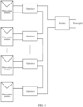
- the power conversion apparatus 200 is an optimizer in a photovoltaic power system
- an output impedance of the optimizer is 1 kohm.
- a quantity of optimizers that are connected in this series branch can also be determined. For example, when output ends of 20 optimizers are connected in series, if a measured total impedance of this series branch is 20 kohm, it indicates that the optimizers in series normally work and wiring is normal. If a measured total impedance of this series branch is another value, it indicates that wiring in series is abnormal or some optimizers in this series branch are abnormal. The total impedance of this series branch may be measured by using a multimeter or another impedance detection apparatus. Likewise, when the output ends of the plurality of the optimizers in series shown in FIG. 6 are connected in parallel, a total impedance obtained after parallel connection may be tested to determine whether an optimizer is faulty or wiring is abnormal.
- this application further provides a method for controlling an output impedance of a power conversion apparatus.
- An output impedance of the power conversion apparatus when no signal is input and an output impedance of the power conversion apparatus when a signal is input but no signal is output are set, to make corresponding output impedances of the power conversion apparatus different when the power conversion apparatus is in different working statuses (for example, the power conversion apparatus is faulty or there is no input to the power conversion apparatus).
- the working status of the power conversion apparatus can be represented by the output impedance of the power conversion apparatus.
- the power conversion apparatus is configured to adjust power input to the power conversion apparatus and output adjusted power, and may specifically be an optimizer.
- the method for controlling the output impedance of the power conversion apparatus mainly includes the following steps:
- the power conversion apparatus includes a power conversion circuit, an impedance adjustable circuit, and a control circuit, where the control circuit is connected to both the power conversion circuit and the impedance adjustable circuit, and an output end of the power conversion circuit is connected to the impedance adjustable circuit, that is, in a scenario in which the power conversion apparatus is of the structure shown in FIG. 2 , the power conversion apparatus specifically makes impedance adjustments in the following manners.
- the power conversion apparatus adjusts the output impedance of the power conversion apparatus to the first impedance when the power conversion apparatus does not satisfy the start condition as follows: adjusting an impedance of the impedance adjustable circuit to a third impedance when the power conversion apparatus does not satisfy the start condition, where the third impedance is determined based on an equivalent impedance of the power conversion circuit when the power conversion circuit does not satisfy the start condition and the first impedance.
- the power conversion apparatus adjusts the output impedance of the power conversion apparatus to the second impedance when the power conversion apparatus satisfies the start condition as follows: adjusting an impedance of the impedance adjustable circuit to a fourth impedance when the power conversion apparatus satisfies the start condition, where the fourth impedance is determined based on an equivalent impedance of the power conversion circuit when the power conversion circuit satisfies the start condition and the second impedance.
- the impedance adjustable circuit may be implemented by using, but not limited to, the structure shown in FIG. 3 , FIG. 4 , FIG. 5a , or FIG. 5b . When the impedance adjustable circuit is implemented by using the structure shown in FIG. 3 , FIG. 4 , FIG. 5a , or FIG.
- the output impedance of the power conversion apparatus is adjusted to the first impedance when the power conversion apparatus is faulty, or the output impedance of the power conversion apparatus is adjusted to the second impedance when the power conversion apparatus is normal, so that the output impedance of the power conversion apparatus when the power conversion apparatus is faulty is different from the output impedance of the power conversion apparatus when the power conversion apparatus is normal.
- a working status of the power conversion apparatus can be represented by the output impedance of the power conversion apparatus, and the determined working status of the power conversion apparatus is more accurate than a working status of the power conversion apparatus determined in a voltage detection manner in the prior art.
- the output impedance of the power conversion apparatus when the output impedance of the power conversion apparatus is the first impedance, it can be represented that the status of the power conversion apparatus is that the power conversion apparatus is faulty, or that the power conversion apparatus satisfies a start condition but the power conversion apparatus is faulty.
- the output impedance of the power conversion apparatus is the second impedance, it can be represented that the status of the power conversion apparatus is that the power conversion apparatus satisfies the start condition and the power conversion apparatus is normal.
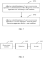
- the photovoltaic power system includes a photovoltaic module, an optimizer, and an inverter.
- the photovoltaic module 1101 is configured to: convert solar energy into electrical energy, and output the obtained electrical energy to the optimizer 1102.
- the optimizer 1102 is configured to: adjust an output impedance of the optimizer 1102 to a first impedance when the optimizer 1102 does not satisfy a start condition, or adjust an output impedance of the optimizer 1102 to a second impedance when the optimizer 1102 satisfies a start condition, where the first impedance is not equal to the second impedance; and when the optimizer 1102 satisfies the start condition and the optimizer 1102 needs to control output power, adjust output power of the photovoltaic module 1101 and output adjusted power.
- the inverter 1103 is configured to: convert the power output by the optimizer 1102 into electrical energy satisfying a specified condition, and output the converted electrical energy to a power grid or a load.
- the optimizer 1102 includes a power conversion circuit, an impedance adjustable circuit, and a control circuit, and the control circuit is connected to both the power conversion circuit and the impedance adjustable circuit, an output end of the power conversion circuit is connected to the impedance adjustable circuit.
- the optimizer 1102 is specifically configured to: adjust an impedance of the impedance adjustable circuit to a third impedance when the optimizer 1102 does not satisfy the start condition, where the third impedance is determined based on an equivalent impedance of the power conversion circuit when the power conversion circuit does not satisfy the start condition and the first impedance; or adjust an impedance of the impedance adjustable circuit to a fourth impedance when the optimizer 1102 satisfies the start condition, where the fourth impedance is determined based on an equivalent impedance of the power conversion circuit when the power conversion circuit satisfies the start condition and the second impedance.
- the impedance adjustable circuit may be implemented by using, but not limited to, the structure shown in FIG. 3 , FIG. 4 , FIG. 5a , or FIG. 5b .
- the impedance adjustable circuit is implemented by using the structure shown in FIG. 3 , FIG. 4 , FIG. 5a , or FIG. 5b , for a method for controlling the output impedance of the impedance adjustable circuit by the optimizer 1102
- the photovoltaic power system may include one or more (two or more) photovoltaic modules 1101 and one or more (two or more) optimizers 1102.
- These computer program instructions may be provided for a general-purpose computer, a dedicated computer, an embedded processor, or a processor of another programmable data processing device to generate a machine, so that the instructions executed by the computer or the processor of the another programmable data processing device generate an apparatus for implementing a specific function in one or more processes in the flowcharts and/or in one or more blocks in the block diagrams.
- These computer program instructions may alternatively be stored in a computer-readable memory that can instruct a computer or another programmable data processing device to work in a specific manner, so that the instructions stored in the computer-readable memory generate an artifact that includes an instruction apparatus.
- the instruction apparatus implements a specific function in one or more processes in the flowcharts and/or in one or more blocks in the block diagrams.
- These computer program instructions may alternatively be loaded onto a computer or another programmable data processing device, so that a series of operations and steps are performed on the computer or the another programmable device, thereby generating computer-implemented processing. Therefore, the instructions executed on the computer or the another programmable device provide steps for implementing a specific function in one or more processes in the flowcharts and/or in one or more blocks in the block diagrams.
Landscapes
- Engineering & Computer Science (AREA)
- Power Engineering (AREA)
- Dc-Dc Converters (AREA)
- Control Of Electrical Variables (AREA)
- Inverter Devices (AREA)
Description
- This disclosure relates to the field of power converter technologies, and the invention relates in particular to a power conversion apparatus and a method for controlling an output impedance of a power conversion apparatus.
- Photovoltaic (PV) power generation is the most common solar energy utilization manner in which light energy can be directly converted into electrical energy. The PV power generation features high reliability, a long lifespan, environmental protection, and the like. As shown in
FIG. 1 , a photovoltaic power system generally includes photovoltaic modules, optimizers, and an inverter. An input end of the optimizer is connected to an output end of the photovoltaic module, and the optimizer is configured to implement maximum power tracking of the photovoltaic module or rapid power-off. Output ends of a plurality of optimizers are connected in series and then connected to a direct current input end of the inverter, so that output power of the optimizers in series can be adjusted. An alternating current output end of the inverter is connected to a power grid for grid-connected power generation. - In a scenario in which a photovoltaic power system includes optimizers, there are many field wiring cases, and the optimizers are usually installed on rear faces of photovoltaic modules (for example, fastened on supports of the photovoltaic modules or frames of the photovoltaic modules). Whether a single optimizer can normally work needs to be determined after the optimizer is installed, and whether the optimizers in series can normally work needs to be determined after the photovoltaic modules in series and the optimizers in series are installed. In this way, normal installation can be ensured after installation and construction of the photovoltaic modules and the optimizers are completed, and checking of related wiring required due to an optimizer installation problem does not need to be subsequently performed. This avoids complex and strenuous construction operations required for checking optimizer-related wiring. For example, in a scenario in which a photovoltaic power system is installed on a roof, because in the roof scenario, a photovoltaic module is usually installed close to the roof and an optimizer is usually installed between a PV panel and the roof, the photovoltaic module needs to be disassembled for wiring check. In this case, it is difficult to perform a construction operation.
- In the prior art, the following method is used to determine whether an installed optimizer can normally work: After a single optimizer is connected to a photovoltaic module and is powered on, an output voltage is controlled to be 1 V, and whether the optimizer normally works can be determined by testing whether the output voltage of the optimizer is 1 V. After installation of photovoltaic modules in series and optimizers in series is completed, the optimizers are powered on, and an output voltage of each of the optimizers is controlled to be 1 V. A quantity of connected optimizers is determined by testing an output voltage of the optimizers in series. For example, if the measured output voltage of the optimizers in series is 20 V, it can be determined that 20 optimizers normally work. However, the output voltage of the optimizer is relatively low (1 V), and it is quite difficult to ensure actual control precision. After output ends of a plurality of optimizers are connected in series, due to accumulation of voltage deviations and a wire voltage drop, there is a specific deviation from an actually tested output voltage of the optimizers. As a result, an estimated quantity of normal optimizers may be different from that of actually connected optimizers.
-
EP 2 444 872 A2 discloses a switching power supply of a photovoltaic system. It comprises two stages between an input and an output of the switching power supply. The two stages are coupled by an intermediate circuit consisting of a transistor and a resistor. With this intermediate circuit, the second stage is initiated when sufficient power is supplied by the photovoltaic elements.US 5,179,488 relates to a process control instrument with aloop overcurrent circuit.CN 104 079 001 B relates to an optimizer control method based on series-type optimizers in a photovoltaic grid-connected system. The method comprises the following steps: an input voltage of one optimizer is detected; B, whether a photovoltaic module connected with the previous optimizer works or not is judged, wherein if not, the step A is executed, and if yes, the next step C is executed; C, maximum power point tracing is conducted on the photovoltaic module; D, an output voltage of the optimizer is detected; E, whether the output voltage of the optimizer is larger than an upper limit voltage of an output voltage threshold or not is judged, wherein if not, the step C is executed, and if yes, the next step F is executed; F, the optimizer is stopped for a period of time; G whether the output voltage of the optimizer is smaller than a lower limit voltage of the output voltage threshold or not is judged, wherein if not, the step F is executed, and if yes, the next step C is executed. According to the method, requirements for a communication system between the optimizers and between the optimizers and an inverter can be eliminated, power balance of the photovoltaic grid-connected system is kept, and stable starting and protecting functions are guaranteed. Further prior art is provided byUS2017/170782 . - The object of the present invention is to provide a power conversion apparatus and a method for controlling an output impedance of a power conversion apparatus, to resolve a prior-art problem of relatively low accuracy of a method for determining a working status of a power conversion apparatus. This object is solved by the independent claims and further advantageous embodiments and improvements of the invention are listed in the dependent claim. Hereinafter, expressions like "...aspect according to the invention" or "according to the invention" or similar relate to technical teaching of the broadest embodiment as claimed with the independent claims. Expressions like "working mode", "implementation", "scenario" or "optionally" or "optional design" or "may", relate to claimed embodiments, and expressions like "examples" or "according to an example" relate to technical teaching which contributes to the understanding of the claimed invention.
- According to a first aspect according to the invention, the present invention provides a power conversion apparatus. The power conversion apparatus includes a power conversion circuit, an impedance adjustable circuit, and a control circuit. The control circuit is connected to both the power conversion circuit and the impedance adjustable circuit, an input end of the power conversion circuit is configured to connect to a power source, and an output end of the power conversion circuit is connected to the impedance adjustable circuit. The power conversion circuit is configured to adjust output power of the power conversion circuit under the control of the control circuit. The impedance adjustable circuit is configured to adjust an output impedance of the impedance adjustable circuit under the control of the control circuit. The control circuit is configured to: when the power conversion apparatus is faulty, control the impedance adjustable circuit to adjust the impedance of the impedance adjustable circuit to a first impedance, or when the power conversion apparatus is normal, control the impedance adjustable circuit to adjust the impedance of the impedance adjustable circuit to a second impedance, where the first impedance is not equal to the second impedance.
- According to the solution, the output impedance of the impedance adjustable circuit is the first impedance when the power conversion apparatus is faulty, or the output impedance of the impedance adjustable circuit is the second impedance when the power conversion apparatus is normal, so that an output impedance of the power conversion apparatus when the power conversion apparatus is faulty is different from an output impedance of the power conversion apparatus when the power conversion apparatus is normal. In this way, a working status of the power conversion apparatus can be represented by the output impedance of the power conversion apparatus, and the determined working status of the power conversion apparatus is more accurate than a working status of the power conversion apparatus determined in a voltage detection manner in the prior art.
- In a possible implementation, the power conversion apparatus is an optimizer.
- According to the invention, the impedance adjustable circuit is connected in series to the power conversion circuit, the impedance adjustable circuit includes a first switch and a first load circuit, the first switch is connected in parallel to the first load circuit, and the first switch is further connected to the control circuit. According to an implementation, when the power conversion apparatus is faulty, the control circuit controls the first switch to be in a first state; or when the power conversion apparatus is normal, the control circuit controls the first switch to be in a second state, where the second state is a state different from the first state.
- Further, the first state is an off state, and the second state is an on state or switching between an off state and an on state according to a specified law; or the first state is an on state, and the second state is an off state or switching between an off state and an on state according to a specified law.
- Specifically, when the power conversion apparatus is faulty, the first switch is in an on state, and in this case, the first impedance is zero; or when the power conversion apparatus is normal, the first switch is in an off state, and the second impedance is an impedance of the first load circuit. In such a scenario, when the output impedance of the power conversion apparatus is an output impedance of the power conversion circuit, it can be represented that the status of the power conversion apparatus is that the power conversion apparatus is normal, or that the power conversion apparatus satisfies a start condition but the power conversion apparatus is faulty. When the output impedance of the power conversion apparatus is an impedance obtained after an output impedance of the power conversion circuit and the impedance of the first load circuit are connected in series, it can be represented that the status of the power conversion apparatus is that the power conversion apparatus satisfies the start condition and the power conversion apparatus is normal.
- Alternatively, when the power conversion apparatus is faulty, the first switch is in an off state, and in this case, the first impedance is an impedance of the first load circuit; or when the power conversion apparatus is normal, the first switch is in an on state, and the second impedance is zero. In such a scenario, when the output impedance of the power conversion apparatus is an impedance obtained after an output impedance of the power conversion circuit and the impedance of the first load circuit are connected in series, it can be represented that the status of the power conversion apparatus is that the power conversion apparatus is faulty, or that the power conversion apparatus satisfies a start condition but the power conversion apparatus is faulty. When the output impedance of the power conversion apparatus is an output impedance of the power conversion circuit, it can be represented that the status of the power conversion apparatus is that the power conversion apparatus satisfies the start condition and the power conversion apparatus is normal.
- In a possible implementation, when the power conversion apparatus satisfies a start condition, after the control circuit controls the first switch to be in the second state, the control circuit is further configured to: receive first instruction information, and control, according to the first instruction information, the first switch to be in a third state, where the third state is a state different from the second state, so that an output impedance of the power conversion apparatus when the power conversion apparatus normally works is different from the output impedance of the power conversion apparatus when the power conversion apparatus satisfies the start condition; or
when the power conversion apparatus satisfies the start condition, after the control circuit controls the first switch to be in the second state, the control circuit is further configured to: determine whether a voltage, a current, or power of an output end of the power conversion apparatus changes; and when determining that the voltage, the current, or the power of the output end of the power conversion apparatus changes, control the first switch to be in a third state, where the third state is a state different from the second state, so that an output impedance of the power conversion apparatus when the power conversion apparatus normally works is different from the output impedance of the power conversion apparatus when the power conversion apparatus satisfies the start condition. - In a possible implementation, the impedance adjustable circuit is connected in parallel to the power conversion circuit, the impedance adjustable circuit includes a second switch and a second load circuit, the second switch is connected in series to the second load circuit, and the second switch is further connected to the control circuit. When the power conversion apparatus does not satisfy the start condition, the control circuit controls the second switch to be in a first state; or when the power conversion apparatus satisfies the start condition, the control circuit controls the second switch to be in a second state, where the second state is a state different from the first state.
- Further, the first state is an off state, and the second state is an on state; or the first state is an on state, and the second state is an off state.
- Specifically, when the power conversion apparatus does not satisfy the start condition, the second switch is in an on state, and the first impedance is an output impedance of the second load circuit; or when the power conversion apparatus satisfies the start condition, the second switch is in an off state, and the second impedance is infinitely large. In such a scenario, when the output impedance of the power conversion apparatus is an impedance obtained after an output impedance of the power conversion circuit and the output impedance of the second load circuit are connected in parallel, it can be represented that the status of the power conversion apparatus is that the power conversion apparatus does not satisfy the start condition, or that the power conversion apparatus satisfies the start condition but the power conversion apparatus is faulty. When the output impedance of the power conversion apparatus is an output impedance of the power conversion circuit, it can be represented that the status of the power conversion apparatus is that the power conversion apparatus satisfies the start condition and the power conversion apparatus is normal.
- Alternatively, when the power conversion apparatus does not satisfy the start condition, the second switch is in an off state, and the first impedance is infinitely large; or when the power conversion apparatus satisfies the start condition, the second switch is in an on state, and the second impedance is an output impedance of the second load circuit. In such a scenario, when the output impedance of the power conversion apparatus is an output impedance of the power conversion circuit, it can be represented that the status of the power conversion apparatus is that the power conversion apparatus does not satisfy the start condition, or that the power conversion apparatus satisfies the start condition but the power conversion apparatus is faulty. When the output impedance of the power conversion apparatus is an impedance obtained after an output impedance of the power conversion circuit and the output impedance of the second load circuit are connected in parallel, it can be represented that the status of the power conversion apparatus is that the power conversion apparatus satisfies the start condition and the power conversion apparatus is normal.
- In a possible implementation, when the power conversion apparatus satisfies the start condition, after the control circuit controls the second switch to be in the second state, the control circuit is further configured to: receive first instruction information, and control, according to the first instruction information, the second switch to be in a third state, where the third state is a state different from the second state; or
when the power conversion apparatus satisfies the start condition, after the control circuit controls the second switch to be in the second state, the control circuit is further configured to: determine whether a voltage, a current, or power of an output end of the power conversion apparatus changes; and when determining that the voltage, the current, or the power of the output end of the power conversion apparatus changes, control the second switch to be in a third state, where the third state is a state different from the second state. - In a possible implementation, the impedance adjustable circuit includes a first impedance adjustable circuit and a second impedance adjustable circuit, a first end of the first impedance adjustable circuit is connected, according to the invention, in series to a first output end of the power conversion circuit, and the second impedance adjustable circuit is connected in parallel between a second end of the first impedance adjustable circuit and a second output end of the power conversion circuit, or the second impedance adjustable circuit is connected in parallel to the power conversion circuit, and the first impedance adjustable circuit is connected in series to the second impedance adjustable circuit, where the first impedance adjustable circuit includes a first switch and a first load circuit, the first switch is connected in parallel to the first load circuit, the second impedance adjustable circuit includes a second switch and a second load circuit, the second switch is connected in series to the second load circuit, and the first switch and the second switch are further connected to the control circuit. When the power conversion apparatus does not satisfy the start condition, the control circuit controls the first switch to be in a first state, and controls the second switch to be in a first state or a second state, where the second state is a state different from the first state; or when the power conversion apparatus satisfies the start condition, the control circuit controls at least one of the first switch and the second switch to be in a state that is different from a state corresponding to the at least one switch when the power conversion apparatus does not satisfy the start condition.
- Further, the first state is an off state, the second state is an on state, a state different from the first state is an on state, and a state different from the second state is an off state; or
- the first state is an off state, the second state is an off state, a state different from the first state is an on state, and a state different from the second state is an on state or; or
- the first state is an on state, the second state is an off state, a state different from the first state is an off state, and a state different from the second state is an on state; or
- the first state is an on state, the second state is an on state, a state different from the first state is an off state, and a state different from the second state is an off state, where the first law may be the same as or different from the second law.
- In a possible implementation, when the power conversion apparatus satisfies the start condition, after the control circuit controls the at least one of the first switch and the second switch to be in the state that is different from the state corresponding to the at least one switch when the power conversion apparatus does not satisfy the start condition, the control circuit is further configured to: receive first instruction information, and control, according to the first instruction information, at least one of the first switch and the second switch to be in a state that is different from a state corresponding to the at least one switch when the power conversion apparatus satisfies the start condition; or
when the power conversion apparatus satisfies the start condition, after the control circuit controls the at least one of the first switch and the second switch to be in the state that is different from the state corresponding to the at least one switch when the power conversion apparatus does not satisfy the start condition, the control circuit is further configured to: determine whether a voltage, a current, or power of an output end of the power conversion apparatus changes; and when determining that the voltage, the current, or the power of the output end of the power conversion apparatus changes, control at least one of the first switch and the second switch to be in a state that is different from a state corresponding to the at least one switch when the power conversion apparatus satisfies the start condition. - In a possible not claimed implementation, when the power conversion apparatus satisfies the start condition, before the control circuit controls the impedance adjustable circuit to adjust the impedance of the impedance adjustable circuit to the second impedance, the control circuit is further configured to determine that the power conversion apparatus can normally work.
- According to a second aspect according to the invention, the invention further provides a method for controlling an output impedance of a power conversion apparatus. The method includes: adjusting the output impedance of the power conversion apparatus to a first impedance when the power conversion apparatus is faulty; or adjusting the output impedance of the power conversion apparatus to a second impedance when the power conversion apparatus is normal, where the first impedance is not equal to the second impedance.
- According to the method, the output impedance of the power conversion apparatus is adjusted to the first impedance when the power conversion apparatus is faulty, or the output impedance of the power conversion apparatus is adjusted to the second impedance when the power conversion apparatus is normal, so that the output impedance of the power conversion apparatus when the power conversion apparatus is faulty is different from the output impedance of the power conversion apparatus when the power conversion apparatus is normal. In this way, a working status of the power conversion apparatus can be represented by the output impedance of the power conversion apparatus, and the determined working status of the power conversion apparatus is more accurate than a working status of the power conversion apparatus determined in a voltage detection manner in the prior art. Specifically, when the output impedance of the power conversion apparatus is the first impedance, it can be represented that the status of the power conversion apparatus is that the power conversion apparatus is faulty, or that the power conversion apparatus satisfies a start condition but the power conversion apparatus is faulty. When the output impedance of the power conversion apparatus is the second impedance, it can be represented that the status of the power conversion apparatus is that the power conversion apparatus satisfies the start condition and the power conversion apparatus is normal.
- In a possible but not claimed implementation, the power conversion apparatus includes a power conversion circuit, an impedance adjustable circuit, and a control circuit. The control circuit is connected to both the power conversion circuit and the impedance adjustable circuit, and an output end of the power conversion circuit is connected to the impedance adjustable circuit. The adjusting the output impedance of the power conversion apparatus to a first impedance when the power conversion apparatus does not satisfy a start condition includes: adjusting an impedance of the impedance adjustable circuit to a third impedance when the power conversion apparatus does not satisfy the start condition, where the third impedance is determined based on an equivalent impedance of the power conversion circuit when the power conversion circuit does not satisfy the start condition and the first impedance. The adjusting the output impedance of the power conversion apparatus to a second impedance when the power conversion apparatus satisfies a start condition includes: adjusting an impedance of the impedance adjustable circuit to a fourth impedance when the power conversion apparatus satisfies the start condition, where the fourth impedance is determined based on an equivalent impedance of the power conversion circuit when the power conversion circuit satisfies the start condition and the second impedance.
- According to a third not claimed aspect, this application further provides a not claimed photovoltaic power system. The system includes a photovoltaic module, an optimizer, and an inverter. The photovoltaic module is configured to: convert solar energy into electrical energy, and output the electrical energy to the optimizer. The optimizer is configured to: adjust an output impedance of the optimizer to a first impedance when the optimizer does not satisfy a start condition, or adjust an output impedance of the optimizer to a second impedance when the optimizer satisfies a start condition, where the first impedance is not equal to the second impedance; and when the optimizer satisfies the start condition and the optimizer needs to control output power, adjust output power of the photovoltaic module and output adjusted power. The inverter is configured to: convert the power output by the optimizer into electrical energy satisfying a specified condition, and output the converted electrical energy to a power grid or a load.
- In a possible but not claimed implementation, the optimizer includes a power conversion circuit, an impedance adjustable circuit, and a control circuit. The control circuit is connected to both the power conversion circuit and the impedance adjustable circuit, and an output end of the power conversion circuit is connected to the impedance adjustable circuit. The optimizer is specifically configured to: adjust an impedance of the impedance adjustable circuit to a third impedance when the optimizer does not satisfy the start condition, where the third impedance is determined based on an equivalent impedance of the power conversion circuit when the power conversion circuit does not satisfy the start condition and the first impedance; or adjust an impedance of the impedance adjustable circuit to a fourth impedance when the optimizer satisfies the start condition, where the fourth impedance is determined based on an equivalent impedance of the power conversion circuit when the power conversion circuit satisfies the start condition and the second impedance.
-
-
FIG. 1 is a schematic structural diagram of a photovoltaic power system in the prior art; -
FIG. 2 is a schematic structural diagram 1 of a power conversion apparatus according to an embodiment of this application; -
FIG. 3 is a schematic structural diagram 2 of a power conversion apparatus according to an embodiment of this application; -
FIG. 4 is a schematic structural diagram 3 of a power conversion apparatus not in accordance with the invention; -
FIG. 5a is a schematic structural diagram 4 of a power conversion apparatus according to an embodiment of this application; -
FIG. 5b is a schematic structural diagram 5 of a power conversion apparatus according to an embodiment of this application; -
FIG. 6 is a schematic diagram of a connection manner of a power conversion apparatus according to an embodiment of this application; -
FIG. 7 is a schematic flowchart of a method for controlling an output impedance of a power conversion apparatus according to an embodiment of this application; and -
FIG. 8 is a schematic structural diagram of a photovoltaic power system according to an embodiment of this application. - In the following description, features which in the above summary of the invention have been marked as "not claimed" or "according to the invention" are also hereinafter, when they are described and explained with reference to the drawings, to be understood as "not claimed" or "not part of the invention" or "according to the invention". If the above features marked "in accordance with the invention" or "the invention" are referred to, in the following description of embodiments of the invention, in connection with the words "can", "may" or any other optional expression, it should be understood that they are not optional but essential for the invention as claimed.
- In a scenario in which a photovoltaic power system includes optimizers, there are many field wiring cases, and the optimizers are usually installed on rear faces of photovoltaic modules (for example, fastened on supports of the photovoltaic modules or frames of the photovoltaic modules). Therefore, in an installation process of the photovoltaic system, whether the optimizers can normally work needs to be determined after the photovoltaic modules and the optimizers are installed. In this way, normal installation can be ensured after installation and construction of the photovoltaic modules and the optimizers are completed, and checking of related wiring required due to an optimizer installation problem does not need to be subsequently performed. This avoids complex and strenuous construction operations required for checking optimizer-related wiring.
- In the prior art, after a single optimizer is connected to a photovoltaic module and is powered on, an output voltage is controlled to be 1 V, and whether the optimizer normally works can be determined by testing whether the output voltage of the optimizer is 1 V. However, the output voltage of the optimizer is relatively low (1 V), and it is quite difficult to ensure actual control precision. After output ends of a plurality of optimizers are connected in series, due to accumulation of voltage deviations and a wire voltage drop, there is a specific deviation from an actually tested output voltage of the optimizers. As a result, an estimated quantity of normal optimizers may be different from that of actually connected optimizers.
- To resolve the foregoing prior-art problem and improve accuracy of a determined working status of a power conversion apparatus, this application provides a power conversion apparatus and a method for controlling an output impedance of a power conversion apparatus. An output impedance of the power conversion apparatus when no signal is input and an output impedance of the power conversion apparatus when a signal is input but no signal is output are set, to make corresponding output impedances of the power conversion apparatus different when the power conversion apparatus is in different working statuses (for example, the power conversion apparatus is faulty or there is no input to the power conversion apparatus). In this way, the working status of the power conversion apparatus can be represented by the output impedance of the power conversion apparatus.
- In addition, it should be understood that in the descriptions of this application, terms such as "first" and "second" are only used for description differentiation, but cannot be understood as indication or implication of relative importance and cannot be understood as indication or implication of sequences; "and/or describes an association relationship for describing associated objects, and represents that three relationships may exist. For example, A and/or B may represent the following cases: Only A exists, both A and B exist, and only B exists. The character "/" generally indicates an "or" relationship between associated objects; "a plurality of" means two or more.
- To make the objectives, technical solutions, and advantages of this application clearer, the following further describes this application in detail with reference to the accompanying drawings.
- As shown in
FIG. 2 , this application provides apower conversion apparatus 200. Thepower conversion apparatus 200 includes apower conversion circuit 210, an impedanceadjustable circuit 220, and acontrol circuit 230. Thecontrol circuit 230 is connected to both thepower conversion circuit 210 and the impedanceadjustable circuit 220, an input end of thepower conversion circuit 210 is configured to connect to a power source, and an output end of thepower conversion circuit 210 is connected to the impedanceadjustable circuit 220. Specifically, thepower conversion circuit 210 is configured to adjust output power of thepower conversion circuit 210 under the control of thecontrol circuit 230. The impedanceadjustable circuit 220 is configured to adjust an output impedance of the impedanceadjustable circuit 220 under the control of thecontrol circuit 230. Thecontrol circuit 230 is configured to: when thepower conversion apparatus 200 does not satisfy a start condition, control the impedanceadjustable circuit 220 to adjust the impedance of the impedanceadjustable circuit 220 to a first impedance, or when thepower conversion apparatus 200 satisfies a start condition, control the impedanceadjustable circuit 220 to adjust the impedance of the impedanceadjustable circuit 220 to a second impedance, where the first impedance is not equal to the second impedance. - Further, the
power conversion apparatus 200 may be an optimizer, and the start condition of thepower conversion apparatus 200 is that input power of thepower conversion apparatus 200 is greater than or equal to minimum power-on operating power of thecontrol circuit 230. - During specific implementation, the impedance adjustable circuit may be implemented in a manner shown in
FIG. 3 . The impedanceadjustable circuit 220 is connected in series to thepower conversion circuit 210, the impedanceadjustable circuit 220 includes a first switch K1 and afirst load circuit 221, the first switch K1 is connected in parallel to thefirst load circuit 221, and the first switch K1 is further connected to thecontrol circuit 230. When thepower conversion apparatus 200 does not satisfy the start condition, thecontrol circuit 230 controls the first switch K1 to be in a first state; or when thepower conversion apparatus 200 satisfies the start condition, thecontrol circuit 230 controls the first switch K1 to be in a second state, where the second state is a state different from the first state. - The first state may be an off state, and in this case, the second state may be an on state or switching between an off state and an on state according to a specified law; or the first state may be an on state, and in this case, the second state is an off state or switching between an off state and an on state according to a specified law.
- Specifically, when the
power conversion apparatus 200 does not satisfy the start condition, the first switch K1 is in an on state, and in this case, the first impedance is zero; or when thepower conversion apparatus 200 satisfies the start condition, the first switch K1 is in an off state, and the second impedance is an impedance of thefirst load circuit 221. In such a scenario, when an output impedance of thepower conversion apparatus 200 is an output impedance of thepower conversion circuit 210, it can be represented that a status of thepower conversion apparatus 200 is that thepower conversion apparatus 200 does not satisfy the start condition, or that thepower conversion apparatus 200 satisfies the start condition but thepower conversion apparatus 200 is faulty. When an output impedance of thepower conversion apparatus 200 is an impedance obtained after an output impedance of thepower conversion circuit 210 and the impedance of thefirst load circuit 221 are connected in series, it can be represented that thepower conversion apparatus 200 satisfies the start condition and that thepower conversion apparatus 200 is normal. - Alternatively, when the
power conversion apparatus 200 does not satisfy the start condition, the first switch K1 is in an off state, and in this case, the first impedance is an impedance of thefirst load circuit 221; or when thepower conversion apparatus 200 satisfies the start condition, the first switch K1 is in an on state, and the second impedance is zero. In such a scenario, when an output impedance of thepower conversion apparatus 200 is an impedance obtained after an output impedance of thepower conversion circuit 210 and the impedance of thefirst load circuit 221 are connected in series, it can be represented that a status of thepower conversion apparatus 200 is that thepower conversion apparatus 200 does not satisfy the start condition, or that thepower conversion apparatus 200 satisfies the start condition but thepower conversion apparatus 200 is faulty. When an output impedance of thepower conversion apparatus 200 is an output impedance of thepower conversion circuit 210, it can be represented that a status of thepower conversion apparatus 200 is that thepower conversion apparatus 200 satisfies the start condition and that thepower conversion apparatus 200 is normal. - Further, when the
power conversion apparatus 200 satisfies the start condition, after thecontrol circuit 230 controls the first switch K1 to be in the second state, theapparatus 200 is further configured to: receive first instruction information, and control, according to the first instruction information, the first switch K1 to be in a third state, where the third state is a state different from the second state, so that an output impedance of thepower conversion apparatus 200 when thepower conversion apparatus 200 normally works is different from an output impedance of thepower conversion apparatus 200 when thepower conversion apparatus 200 satisfies the start condition. For example, when the second state is an on state, the third state is an off state; or when the second state is an off state, the third state is an on state. Alternatively, when the second state is that the first switch K1 is switched between an off state and an on state according to a specified law, the third state is also that the first switch K1 is switched between an off state and an on state according to the specified law, but at least one of frequency at which the first switch K1 is switched between an off state and an on state and duration during which the first switch K1 is in an off state (or an on state) in the second state is different from corresponding frequency and/or corresponding duration in the third state. - In a specific implementation, when the
power conversion apparatus 200 satisfies the start condition, after thecontrol circuit 230 controls the first switch K1 to be in the second state, theapparatus 200 is further configured to: receive the first instruction information, where the first instruction information is used to instruct thecontroller 230 to control work of thepower conversion circuit 210; and according to the first instruction information, control the first switch K1 to be in an on state, control thepower conversion circuit 210 to adjust power input to thepower conversion circuit 210, and output adjusted power, so that when thepower conversion circuit 210 works, thefirst load circuit 221 is short-circuit, and therefore thefirst load circuit 221 does not affect normal work of thepower conversion apparatus 200. - Alternatively, when the
power conversion apparatus 200 satisfies the start condition, after thecontrol circuit 230 controls the first switch K1 to be in the second state, theapparatus 200 is further configured to: detect whether a voltage, a current, or power of an output end of thepower conversion apparatus 200 changes; and when determining that the voltage, the current, or the power of the output end of thepower conversion apparatus 200 changes, control the first switch K1 to be in a third state, where the third state is a state different from the second state, so that an output impedance of thepower conversion apparatus 200 when thepower conversion apparatus 200 normally works is different from an output impedance of thepower conversion apparatus 200 when thepower conversion apparatus 200 satisfies the start condition. For example, when the second state is an on state, the third state is an off state; or when the second state is an off state, the third state is an on state. Alternatively, when the second state is that the first switch K1 is switched between an off state and an on state according to a specified law, the third state is also that the first switch K1 is switched between an off state and an on state according to the specified law, but at least one of frequency at which the first switch K1 is switched between an off state and an on state and duration during which the first switch K1 is in an off state (or an on state) in the second state is different from corresponding frequency and/or corresponding duration in the third state. - In a specific implementation, when the
power conversion apparatus 200 satisfies the start condition, after thecontrol circuit 230 controls the first switch K1 to be in the second state, theapparatus 200 is further configured to: when determining that the voltage, the current, or the power of the output end of thepower conversion apparatus 200 changes, control the first switch K1 to be closed. In this case, thefirst load circuit 221 is short-circuit, and therefore thefirst load circuit 221 does not affect normal work of thepower conversion apparatus 200. - The impedance adjustable circuit shown in
FIG. 4 is not according to the invention. The impedanceadjustable circuit 220 is connected in parallel to thepower conversion circuit 210, the impedanceadjustable circuit 220 includes a second switch K2 and asecond load circuit 222, the second switch K2 is connected in series to thesecond load circuit 222, and the second switch K2 is further connected to thecontrol circuit 230. When thepower conversion apparatus 200 does not satisfy the start condition, thecontrol circuit 230 controls the second switch K2 to be in a first state; or when thepower conversion apparatus 200 satisfies the start condition, thecontrol circuit 230 controls the second switch K2 to be in a second state, where the second state is a state different from the first state. - The first state may be an off state, and in this case, the second state may be an on state or switching between an off state and an on state according to a first law; or the first state is an on state, and in this case, the second state is an off state or switching between an off state and an on state according to a specified law.
- For example, when the
power conversion apparatus 200 does not satisfy the start condition, the second switch K2 is in an on state, and the first impedance is an output impedance of thesecond load circuit 222; or when thepower conversion apparatus 200 satisfies the start condition, the second switch K2 is in an off state, and the second impedance is infinitely large. In such a scenario, when an output impedance of thepower conversion apparatus 200 is an impedance obtained after an output impedance of thepower conversion circuit 210 and the output impedance of thesecond load circuit 222 are connected in parallel, it can be represented that a status of thepower conversion apparatus 200 is that thepower conversion apparatus 200 does not satisfy the start condition, or that thepower conversion apparatus 200 satisfies the start condition but thepower conversion apparatus 200 is faulty. When an output impedance of thepower conversion apparatus 200 is an output impedance of thepower conversion circuit 210, it can be represented that a status of thepower conversion apparatus 200 is that thepower conversion apparatus 200 satisfies the start condition and that thepower conversion apparatus 200 is normal. - For another example, when the
power conversion apparatus 200 does not satisfy the start condition, the second switch K2 is in an off state, and the first impedance is infinitely large; or when thepower conversion apparatus 200 satisfies the start condition, the second switch K2 is in an on state, and the second impedance is an output impedance of thesecond load circuit 222. In such a scenario, when an output impedance of thepower conversion apparatus 200 is an output impedance of thepower conversion circuit 210, it can be represented that a status of thepower conversion apparatus 200 is that thepower conversion apparatus 200 does not satisfy the start condition, or that thepower conversion apparatus 200 satisfies the start condition but thepower conversion apparatus 200 is faulty. When an output impedance of thepower conversion apparatus 200 is an impedance obtained after an output impedance of thepower conversion circuit 210 and the output impedance of thesecond load circuit 222 are connected in parallel, it can be represented that a status of thepower conversion apparatus 200 is that thepower conversion apparatus 200 satisfies the start condition and that thepower conversion apparatus 200 is normal. - Further, when the
power conversion apparatus 200 satisfies the start condition, after thecontrol circuit 230 controls the second switch to be in the second state, theapparatus 200 is further configured to: receive first instruction information, and control, according to the first instruction information, the second switch K2 to be in a third state, where the third state is a state different from the second state, so that an output impedance of thepower conversion apparatus 200 when thepower conversion apparatus 200 normally works is different from an output impedance of thepower conversion apparatus 200 when thepower conversion apparatus 200 satisfies the start condition. For example, when the second state is an on state, the third state is an off state; or when the second state is an off state, the third state is an on state. Alternatively, when the second state is that the second switch K2 is switched between an off state and an on state according to a specified law, the third state is also that the second switch K2 is switched between an off state and an on state according to the specified law, but at least one of frequency at which the second switch K2 is switched between an off state and an on state and duration during which the second switch K2 is in an off state (or an on state) in the second state is different from corresponding frequency and/or corresponding duration in the third state. - In a specific implementation, when the
power conversion apparatus 200 satisfies the start condition, after thecontrol circuit 230 controls the second switch K2 to be in the second state, theapparatus 200 is further configured to: receive the first instruction information, where the first instruction information is used to instruct thecontrol circuit 230 to control work of thepower conversion circuit 210; and according to the first instruction information, control the second switch K2 to be open, control thepower conversion circuit 210 to adjust power input to thepower conversion circuit 210, and output adjusted power, so that when thepower conversion circuit 210 works, thesecond load circuit 222 is in an open-circuit state, and therefore thesecond load circuit 222 does not affect normal work of thepower conversion apparatus 200. - Alternatively, when the
power conversion apparatus 200 satisfies the start condition, after thecontrol circuit 230 controls the second switch K2 to be in the second state, theapparatus 200 is further configured to: detect whether a voltage, a current, or power of an output end of thepower conversion apparatus 200 changes; and when determining that the voltage, the current, or the power of the output end of thepower conversion apparatus 200 changes, control the second switch K2 to be in a third state, where the third state is a state different from the second state, so that an output impedance of thepower conversion apparatus 200 when thepower conversion apparatus 200 normally works is different from an output impedance of thepower conversion apparatus 200 when thepower conversion apparatus 200 satisfies the start condition. For example, when the second state is an on state, the third state is an off state; or when the second state is an off state, the third state is an on state. Alternatively, when the second state is that the second switch K2 is switched between an off state and an on state according to a specified law, the third state is also that the second switch K2 is switched between an off state and an on state according to the specified law, but at least one of frequency at which the second switch K2 is switched between an off state and an on state and duration during which the second switch K2 is in an off state (or an on state) in the second state is different from corresponding frequency and/or corresponding duration in the third state. - In a specific implementation, when the
power conversion apparatus 200 satisfies the start condition, after thecontrol circuit 230 controls the second switch K2 to be in the second state, theapparatus 200 is further configured to: determine whether the voltage, the current, or the power of the output end of thepower conversion apparatus 200 changes; and when determining that the voltage, the current, or the power of the output end of thepower conversion apparatus 200 changes, control the second switch K2 to be open. In this case, thesecond load circuit 222 is in an open-circuit state, and therefore thesecond load circuit 222 does not affect normal work of thepower conversion apparatus 200. - During specific implementation, the impedance
adjustable circuit 220 may alternatively be implemented in a manner shown inFIG. 5a . The impedanceadjustable circuit 220 includes a first impedance adjustable circuit and a second impedance adjustable circuit, a first end of the first impedance adjustable circuit is connected in series to a first output end of thepower conversion circuit 210, and the second impedance adjustable circuit is connected in parallel between a second end of the first impedance adjustable circuit and a second output end of thepower conversion circuit 210, and the first switch K1 and the second switch K2 are further connected to thecontrol circuit 230. Alternatively, as shown inFIG. 5b , the second impedance adjustable circuit is connected in parallel to thepower conversion circuit 210, and the first impedance adjustable circuit is connected in series to the second impedance adjustable circuit. The first impedance adjustable circuit includes a first switch K1 and afirst load circuit 221, the first switch K1 is connected in parallel to thefirst load circuit 221, the second impedance adjustable circuit includes a second switch K2 and asecond load circuit 222, the second switch K2 is connected in series to thesecond load circuit 222, and the first switch K1 and the second switch K2 are further connected to thecontrol circuit 230. - When the
power conversion apparatus 200 does not satisfy the start condition, thecontrol circuit 230 controls the first switch K1 to be in a first state, and controls the second switch K2 to be in a first state or a second state; or when thepower conversion apparatus 200 satisfies the start condition, thecontrol circuit 230 controls at least one of the first switch K1 and the second switch K2 to be in a state that is different from a state corresponding to the at least one switch when thepower conversion apparatus 200 does not satisfy the start condition. - The first state may be an off state, and the second state may be an on state, and in this case, a state different from the first state is an on state or switching between an off state and an on state according to a first law, and a state different from the second state is an off state or switching between an off state and an on state according to a second law; or
- the first state is an off state, and the second state is an off state, and in this case, a state different from the first state is an on state or switching between an off state and an on state according to a first law, and a state different from the second state is an on state or switching between an off state and an on state according to a second law; or
- the first state is an on state, and the second state is an off state, and in this case, a state different from the first state is an off state or switching between an off state and an on state according to a first law, and a state different from the second state is an on state or switching between an off state and an on state according to a second law; or
- the first state is an on state, and the second state is an on state, and in this case, a state different from the first state is an off state or switching between an off state and an on state according to a first law, and a state different from the second state is an off state or switching between an off state and an on state according to a second law, where the first law may be the same as or different from the second law.
- For example, when the
power conversion apparatus 200 does not satisfy the start condition, the first switch K1 is in an on state, the second switch K2 is in an on state, and the first impedance is an output impedance of thesecond load circuit 222; or when thepower conversion apparatus 200 satisfies the start condition, the first switch K1 is in an off state, the second switch K2 is in an off state, and the second impedance is an output impedance of thefirst load circuit 221. In such a scenario, when an output impedance of thepower conversion apparatus 200 is an impedance obtained after an output impedance of thepower conversion circuit 210 and the output impedance of thesecond load circuit 222 are connected in parallel, it can be represented that a status of thepower conversion apparatus 200 is that thepower conversion apparatus 200 does not satisfy the start condition, or that thepower conversion apparatus 200 satisfies the start condition but thepower conversion apparatus 200 is faulty. When an output impedance of thepower conversion apparatus 200 is an impedance obtained after an output impedance of thepower conversion circuit 210 and the output impedance of thefirst load circuit 221 are connected in series, it can be represented that a status of thepower conversion apparatus 200 is that thepower conversion apparatus 200 satisfies the start condition and that thepower conversion apparatus 200 is normal. Alternatively, when thepower conversion apparatus 200 does not satisfy the start condition, the first switch K1 is in an off state, the second switch K2 is in an off state, and the first impedance is an output impedance of thefirst load circuit 221; or when thepower conversion apparatus 200 satisfies the start condition, the first switch K1 is in an on state, the second switch K2 is in an on state, and the second impedance is an output impedance of thesecond load circuit 222. In such a scenario, when an output impedance of thepower conversion apparatus 200 is an impedance obtained after an output impedance of thepower conversion circuit 210 and the output impedance of thefirst load circuit 221 are connected in series, it can be represented that a status of thepower conversion apparatus 200 is that thepower conversion apparatus 200 does not satisfy the start condition, or that thepower conversion apparatus 200 satisfies the start condition but thepower conversion apparatus 200 is faulty. When an output impedance of thepower conversion apparatus 200 is an impedance obtained after an output impedance of thepower conversion circuit 210 and the output impedance of thesecond load circuit 222 are connected in parallel, it can be represented that a status of thepower conversion apparatus 200 is that thepower conversion apparatus 200 satisfies the start condition and that thepower conversion apparatus 200 is normal. - For another example, when the
power conversion apparatus 200 does not satisfy the start condition, the first switch K1 is in an on state, the second switch K2 is in an off state, and the first impedance is zero; or when thepower conversion apparatus 200 satisfies the start condition, the first switch K1 is in an off state, the second switch K2 is in an off state, and the second impedance is an output impedance of thefirst load circuit 221. In such a scenario, when an output impedance of thepower conversion apparatus 200 is an output impedance of thepower conversion circuit 210, it can be represented that a status of thepower conversion apparatus 200 is that thepower conversion apparatus 200 does not satisfy the start condition, or that thepower conversion apparatus 200 satisfies the start condition but thepower conversion apparatus 200 is faulty. When an output impedance of thepower conversion apparatus 200 is an impedance obtained after an output impedance of thepower conversion circuit 210 and the output impedance of thefirst load circuit 221 are connected in series, it can be represented that a status of thepower conversion apparatus 200 is that thepower conversion apparatus 200 satisfies the start condition and that thepower conversion apparatus 200 is normal. Alternatively, when thepower conversion apparatus 200 does not satisfy the start condition, the first switch K1 is in an off state, the second switch K2 is in an off state, and the first impedance is an output impedance of thefirst load circuit 221; or when thepower conversion apparatus 200 satisfies the start condition, the first switch K1 is in an on state, the second switch K2 is in an off state, and the second impedance is zero. In such a scenario, when an output impedance of thepower conversion apparatus 200 is an impedance obtained after an output impedance of thepower conversion circuit 210 and the output impedance of thefirst load circuit 221 are connected in series, it can be represented that a status of thepower conversion apparatus 200 is that thepower conversion apparatus 200 does not satisfy the start condition, or that thepower conversion apparatus 200 satisfies the start condition but thepower conversion apparatus 200 is faulty. When an output impedance of thepower conversion apparatus 200 is an output impedance of thepower conversion circuit 210, it can be represented that a status of thepower conversion apparatus 200 is that thepower conversion apparatus 200 satisfies the start condition and that thepower conversion apparatus 200 is normal. - For still another example, when the
power conversion apparatus 200 does not satisfy the start condition, the first switch K1 is in an on state, the second switch K2 is in an off state, and the first impedance is zero; or when thepower conversion apparatus 200 satisfies the start condition, the first switch K1 is in an on state, the second switch K2 is in an on state, and the second impedance is an output impedance of thesecond load circuit 222. In such a scenario, when an output impedance of thepower conversion apparatus 200 is an output impedance of thepower conversion circuit 210, it can be represented that a status of thepower conversion apparatus 200 is that thepower conversion apparatus 200 does not satisfy the start condition, or that thepower conversion apparatus 200 satisfies the start condition but thepower conversion apparatus 200 is faulty. When an output impedance of thepower conversion apparatus 200 is an impedance obtained after an output impedance of thepower conversion circuit 210 and the output impedance of thesecond load circuit 222 are connected in parallel, it can be represented that a status of thepower conversion apparatus 200 is that thepower conversion apparatus 200 satisfies the start condition and that thepower conversion apparatus 200 is normal. Alternatively, when thepower conversion apparatus 200 does not satisfy the start condition, the first switch K1 is in an on state, the second switch K2 is in an on state, and the first impedance is an output impedance of thesecond load circuit 222; or when thepower conversion apparatus 200 satisfies the start condition, the first switch K1 is in an on state, the second switch K2 is in an off state, and the second impedance is zero. In such a scenario, when an output impedance of thepower conversion apparatus 200 is an impedance obtained after an output impedance of thepower conversion circuit 210 and the output impedance of thesecond load circuit 222 are connected in parallel, it can be represented that a status of thepower conversion apparatus 200 is that thepower conversion apparatus 200 does not satisfy the start condition, or that thepower conversion apparatus 200 satisfies the start condition but thepower conversion apparatus 200 is faulty. When an output impedance of thepower conversion apparatus 200 is an output impedance of thepower conversion circuit 210, it can be represented that a status of thepower conversion apparatus 200 is that thepower conversion apparatus 200 satisfies the start condition and that thepower conversion apparatus 200 is normal. - It should be noted that the foregoing only uses examples for describing the possible states of the first switch K1 and the second switch K2 when the
power conversion apparatus 200 does not satisfy the start condition and thepower conversion apparatus 200 satisfies the start condition. When the first switch K1 and the second switch K2 are in other possible states, the output impedance of thepower conversion apparatus 200 and the working status represented by the output impedance of thepower conversion apparatus 200 are similar to those in the foregoing several possible scenarios. Details are not described herein again. - Further, when the
power conversion apparatus 200 satisfies the start condition, after thecontrol circuit 230 controls the at least one of the first switch K1 and the second switch K2 to be in the state that is different from the state corresponding to the at least one switch when thepower conversion circuit 200 does not satisfy the start condition, theapparatus 200 is further configured to: receive first instruction information, and control, according to the first instruction information, at least one of the first switch K1 and the second switch K2 to be in a state that is different from a state corresponding to the at least one switch when thepower conversion apparatus 200 satisfies the start condition, so that an output impedance of thepower conversion apparatus 200 when thepower conversion apparatus 200 normally works is different from an output impedance of thepower conversion apparatus 200 when thepower conversion apparatus 200 satisfies the start condition. - For example, after the
control circuit 230 controls the at least one of the first switch K1 and the second switch K2 to be in the state that is different from the state corresponding to the at least one switch when thepower conversion apparatus 200 does not satisfy the start condition, theapparatus 200 is further configured to: receive the first instruction information, where the first instruction information is used to instruct thecontrol circuit 230 to control work of thepower conversion circuit 210; and according to the first instruction information, control the first switch K1 to be closed and the second switch K2 to be open, control thepower conversion circuit 210 to adjust power input to the power conversion circuit, and output adjusted power, so that when thepower conversion circuit 210 works, thefirst load circuit 221 is short-circuit and thesecond load circuit 222 is in an open-circuit state, and therefore thefirst load circuit 221 and thesecond load circuit 222 do not affect normal work of thepower conversion apparatus 200. - Alternatively, when the
power conversion apparatus 200 satisfies the start condition, after thecontrol circuit 230 controls the at least one of the first switch K1 and the second switch K2 to be in the state that is different from the state corresponding to the at least one switch when thepower conversion apparatus 200 does not satisfy the start condition, theapparatus 200 is further configured to: detect whether a voltage, a current, or power of an output end of thepower conversion apparatus 200 changes; and when determining that the voltage, the current, or the power of the output end of thepower conversion apparatus 200 changes, control at least one of the first switch K1 and the second switch K2 to be in a state that is different from a state corresponding to the at least one switch when thepower conversion apparatus 200 satisfies the start condition, so that an output impedance of thepower conversion apparatus 200 when thepower conversion apparatus 200 normally works is different from an output impedance of thepower conversion apparatus 200 when thepower conversion apparatus 200 satisfies the start condition. - For example, after the
control circuit 230 controls the at least one of the first switch K1 and the second switch K2 to be in the state that is different from the state corresponding to the at least one switch when thepower conversion apparatus 200 does not satisfy the start condition, theapparatus 200 is further configured to: determine whether a voltage, a current, or power of an output end of thepower conversion apparatus 200 changes; and when determining that the voltage, the current, or the power of the output end of thepower conversion apparatus 200 changes, control the first switch K1 to be closed and the second switch K2 to be open. In this case, thefirst load circuit 221 is short-circuit and thesecond load circuit 222 is in an open-circuit state, and therefore thefirst load circuit 221 and thesecond load circuit 222 do not affect normal work of thepower conversion apparatus 200. - It should be noted that a structure of the
power conversion circuit 210 is not specifically limited in the embodiments of this application, and all circuit structures that can implement a power conversion function are applicable to the embodiments of this application. Specific structures of thefirst load circuit 221 and thesecond load circuit 222 are not limited in the embodiments of this application. Thefirst load circuit 221 and thesecond load circuit 222 each may be constituted by at least one of components such as a capacitor, a resistor, and an inductor in a manner of series connection, parallel connection, or series-parallel connection. The output impedances of thefirst load circuit 221 and thesecond load circuit 222 may have one type of impedance characteristic or a combination of impedance characteristic such as a resistive characteristic, an inductive characteristic, a capacitive characteristic, or a rectification characteristic. Impedance characteristics of the output impedances of thefirst load circuit 221 and thesecond load circuit 222 may be identical or different. - In addition, specific types of the first switch K1 and the second switch K2 are not limited in the embodiments of this application. The first switch K1 and the second switch K2 each may be a mechanical switch such as a relay, or may be a semiconductor switch such as a transistor, a metal oxide semiconductor (MOS) transistor, an insulated gate bipolar transistor (IGBT), or a gallium nitride GaN transistor.
- According to the solution, the output impedance of the impedance
adjustable circuit 220 is the first impedance when thepower conversion apparatus 200 does not satisfy the start condition, or the output impedance of the impedanceadjustable circuit 220 is the second impedance when thepower conversion apparatus 200 satisfies the start condition, so that an output impedance of thepower conversion apparatus 200 when thepower conversion apparatus 200 does not satisfy the start condition is different from an output impedance of thepower conversion apparatus 200 when thepower conversion apparatus 200 satisfies the start condition. In this way, the working status of thepower conversion apparatus 200 can be represented by the output impedance of thepower conversion apparatus 200, and the determined working status of the power conversion apparatus is more accurate than a working status of the power conversion apparatus determined in a voltage detection manner in the prior art. Specifically, if the output impedance of thepower conversion apparatus 200 when thepower conversion apparatus 200 does not satisfy the start condition is a (which is determined based on the first impedance and the impedance of the power conversion circuit 210), and the output impedance of thepower conversion apparatus 200 when thepower conversion apparatus 200 satisfies the start condition is b (which is determined based on the second impedance and the impedance of the power conversion circuit 210), when the output impedance of thepower conversion apparatus 200 is a, it can be represented that the status of thepower conversion apparatus 200 is that thepower conversion apparatus 200 does not satisfy the start condition, or that thepower conversion apparatus 200 satisfies the start condition but thepower conversion apparatus 200 is faulty. When the output impedance of thepower conversion apparatus 200 is b, it can be represented that the status of thepower conversion apparatus 200 is that thepower conversion apparatus 200 satisfies the start condition and that thepower conversion apparatus 200 is normal. - For example, when the
power conversion apparatus 200 is an optimizer in a photovoltaic power system, if the optimizer satisfies the start condition and is normal, an output impedance of the optimizer is 1 kohm. In this case, after a single optimizer is connected to a photovoltaic module and is powered on, if it is detected that an output impedance of the optimizer is 1 kohm, it indicates that the optimizer satisfies the start condition and normally works; otherwise, it indicates that the optimizer is faulty. When a plurality of optimizers are connected in series, as shown inFIG. 6 , by measuring a total output impedance of this series branch, whether the optimizers in this series branch are normal can be determined, and a quantity of optimizers that are connected in this series branch can also be determined. For example, when output ends of 20 optimizers are connected in series, if a measured total impedance of this series branch is 20 kohm, it indicates that the optimizers in series normally work and wiring is normal. If a measured total impedance of this series branch is another value, it indicates that wiring in series is abnormal or some optimizers in this series branch are abnormal. The total impedance of this series branch may be measured by using a multimeter or another impedance detection apparatus. Likewise, when the output ends of the plurality of the optimizers in series shown inFIG. 6 are connected in parallel, a total impedance obtained after parallel connection may be tested to determine whether an optimizer is faulty or wiring is abnormal. - Based on a same inventive concept, this application further provides a method for controlling an output impedance of a power conversion apparatus. An output impedance of the power conversion apparatus when no signal is input and an output impedance of the power conversion apparatus when a signal is input but no signal is output are set, to make corresponding output impedances of the power conversion apparatus different when the power conversion apparatus is in different working statuses (for example, the power conversion apparatus is faulty or there is no input to the power conversion apparatus). In this way, the working status of the power conversion apparatus can be represented by the output impedance of the power conversion apparatus. The power conversion apparatus is configured to adjust power input to the power conversion apparatus and output adjusted power, and may specifically be an optimizer.
- As shown in
FIG. 7 , the method for controlling the output impedance of the power conversion apparatus mainly includes the following steps: - S701. Adjust the output impedance of the power conversion apparatus to a first impedance when the power conversion apparatus does not satisfy a start condition.
- S702. Adjust the output impedance of the power conversion apparatus to a second impedance when the power conversion apparatus satisfies a start condition, where the first impedance is not equal to the second impedance.
- Specifically, in a scenario in which the power conversion apparatus includes a power conversion circuit, an impedance adjustable circuit, and a control circuit, where the control circuit is connected to both the power conversion circuit and the impedance adjustable circuit, and an output end of the power conversion circuit is connected to the impedance adjustable circuit, that is, in a scenario in which the power conversion apparatus is of the structure shown in
FIG. 2 , the power conversion apparatus specifically makes impedance adjustments in the following manners. The power conversion apparatus adjusts the output impedance of the power conversion apparatus to the first impedance when the power conversion apparatus does not satisfy the start condition as follows: adjusting an impedance of the impedance adjustable circuit to a third impedance when the power conversion apparatus does not satisfy the start condition, where the third impedance is determined based on an equivalent impedance of the power conversion circuit when the power conversion circuit does not satisfy the start condition and the first impedance. The power conversion apparatus adjusts the output impedance of the power conversion apparatus to the second impedance when the power conversion apparatus satisfies the start condition as follows: adjusting an impedance of the impedance adjustable circuit to a fourth impedance when the power conversion apparatus satisfies the start condition, where the fourth impedance is determined based on an equivalent impedance of the power conversion circuit when the power conversion circuit satisfies the start condition and the second impedance. The impedance adjustable circuit may be implemented by using, but not limited to, the structure shown inFIG. 3 ,FIG. 4 ,FIG. 5a , orFIG. 5b . When the impedance adjustable circuit is implemented by using the structure shown inFIG. 3 ,FIG. 4 ,FIG. 5a , orFIG. 5b , for a method for adjusting the output impedance of the impedance adjustable circuit, reference may be made to the method for controlling a corresponding output impedance of the impedance adjustable circuit by thecontrol circuit 230 in the foregoing apparatus embodiments. Details are not described herein again. - According to the method, the output impedance of the power conversion apparatus is adjusted to the first impedance when the power conversion apparatus is faulty, or the output impedance of the power conversion apparatus is adjusted to the second impedance when the power conversion apparatus is normal, so that the output impedance of the power conversion apparatus when the power conversion apparatus is faulty is different from the output impedance of the power conversion apparatus when the power conversion apparatus is normal. In this way, a working status of the power conversion apparatus can be represented by the output impedance of the power conversion apparatus, and the determined working status of the power conversion apparatus is more accurate than a working status of the power conversion apparatus determined in a voltage detection manner in the prior art. Specifically, when the output impedance of the power conversion apparatus is the first impedance, it can be represented that the status of the power conversion apparatus is that the power conversion apparatus is faulty, or that the power conversion apparatus satisfies a start condition but the power conversion apparatus is faulty. When the output impedance of the power conversion apparatus is the second impedance, it can be represented that the status of the power conversion apparatus is that the power conversion apparatus satisfies the start condition and the power conversion apparatus is normal.
- This disclosure further provides a photovoltaic power system. As shown in
FIG. 8 , the photovoltaic power system includes a photovoltaic module, an optimizer, and an inverter. Thephotovoltaic module 1101 is configured to: convert solar energy into electrical energy, and output the obtained electrical energy to theoptimizer 1102. Theoptimizer 1102 is configured to: adjust an output impedance of theoptimizer 1102 to a first impedance when theoptimizer 1102 does not satisfy a start condition, or adjust an output impedance of theoptimizer 1102 to a second impedance when theoptimizer 1102 satisfies a start condition, where the first impedance is not equal to the second impedance; and when theoptimizer 1102 satisfies the start condition and theoptimizer 1102 needs to control output power, adjust output power of thephotovoltaic module 1101 and output adjusted power. Theinverter 1103 is configured to: convert the power output by theoptimizer 1102 into electrical energy satisfying a specified condition, and output the converted electrical energy to a power grid or a load. - In a scenario in which the
optimizer 1102 includes a power conversion circuit, an impedance adjustable circuit, and a control circuit, and the control circuit is connected to both the power conversion circuit and the impedance adjustable circuit, an output end of the power conversion circuit is connected to the impedance adjustable circuit. Theoptimizer 1102 is specifically configured to: adjust an impedance of the impedance adjustable circuit to a third impedance when theoptimizer 1102 does not satisfy the start condition, where the third impedance is determined based on an equivalent impedance of the power conversion circuit when the power conversion circuit does not satisfy the start condition and the first impedance; or adjust an impedance of the impedance adjustable circuit to a fourth impedance when theoptimizer 1102 satisfies the start condition, where the fourth impedance is determined based on an equivalent impedance of the power conversion circuit when the power conversion circuit satisfies the start condition and the second impedance. - The impedance adjustable circuit may be implemented by using, but not limited to, the structure shown in
FIG. 3 ,FIG. 4 ,FIG. 5a , orFIG. 5b . When the impedance adjustable circuit is implemented by using the structure shown inFIG. 3 ,FIG. 4 ,FIG. 5a , orFIG. 5b , for a method for controlling the output impedance of the impedance adjustable circuit by theoptimizer 1102, reference may be made to the method for controlling a corresponding output impedance of the impedance adjustable circuit by thecontrol circuit 230 in the foregoing apparatus embodiments. Details are not described herein again. - It should be noted that quantities of photovoltaic modules and optimizers included in the photovoltaic power system are not limited in this embodiment of this application. The photovoltaic power system may include one or more (two or more)
photovoltaic modules 1101 and one or more (two or more)optimizers 1102. - This disclosure is described with reference to the flowcharts and/or block diagrams of the method, the device (system), and the computer program product according to the embodiments of this application. It should be understood that computer program instructions may be used to implement each process and/or each block in the flowcharts and/or the block diagrams and a combination of a process and/or a block in the flowcharts and/or the block diagrams. These computer program instructions may be provided for a general-purpose computer, a dedicated computer, an embedded processor, or a processor of another programmable data processing device to generate a machine, so that the instructions executed by the computer or the processor of the another programmable data processing device generate an apparatus for implementing a specific function in one or more processes in the flowcharts and/or in one or more blocks in the block diagrams.
- These computer program instructions may alternatively be stored in a computer-readable memory that can instruct a computer or another programmable data processing device to work in a specific manner, so that the instructions stored in the computer-readable memory generate an artifact that includes an instruction apparatus. The instruction apparatus implements a specific function in one or more processes in the flowcharts and/or in one or more blocks in the block diagrams.
- These computer program instructions may alternatively be loaded onto a computer or another programmable data processing device, so that a series of operations and steps are performed on the computer or the another programmable device, thereby generating computer-implemented processing. Therefore, the instructions executed on the computer or the another programmable device provide steps for implementing a specific function in one or more processes in the flowcharts and/or in one or more blocks in the block diagrams.
Claims (10)
- A power conversion apparatus (200), comprising a power conversion circuit (210), an impedance adjustable circuit (220), and a control circuit (230), wherein the control circuit (230) is connected to both the power conversion circuit (210) and the impedance adjustable circuit (220), an input end of the power conversion circuit (210) is configured to connect to a power source, and an output end of the power conversion circuit (210) is connected to the impedance adjustable circuit (220);the power conversion circuit (210) is configured to adjust output power of the power conversion circuit (210) under the control of the control circuit (230);the impedance adjustable circuit (220) is configured to adjust an output impedance of the impedance adjustable circuit (220) under the control of the control circuit (230); andthe control circuit (230) is configured to: when a working status of the power conversion apparatus (200) is faulty, control the impedance adjustable circuit (220) to adjust the output impedance of the power conversion apparatus (200) to a first impedance, or when the working status of the power conversion apparatus (200) is normal, control the impedance adjustable circuit (220) to adjust the output impedance of the power conversion apparatus (200) to a second impedance, wherein the first impedance is not equal to the second impedance; andwherein the working status of the power conversion apparatus is represented by the output impedance, and the output impedance of the power conversion apparatus (200) when the power conversion apparatus (200) normally works and the working status is normal is different from the output impedance of the power conversion apparatus when the power conversion apparatus (200) is faulty and the working status is faulty;the impedance adjustable circuit (220) comprises a first switch (K1) and a first load circuit (221), the first load circuit (221) being serially connected to the output of the power conversion circuit (210), the first switch (K1) being connected in parallel to the first load circuit (221), and the first switch (K1) being further connected to the control circuit (230).
- The apparatus according to claim 1, configured such that, when the power conversion apparatus (200) is faulty, the control circuit (230) controls the first switch (K1) to be in a first state; or when the power conversion apparatus (200) is normal, the control circuit (230) controls the first switch (K1) to be in a second state, wherein the second state is a state different from the first state.
- The apparatus according to claim 2, wherein the first state is an off state, and the second state is an on state; or the first state is an on state, and the second state is an off state.
- The apparatus according to claim 2 or 3, whereinwhen the power conversion apparatus (200) satisfies a start condition, after the control circuit (230) controls the first switch (K1) to be in the second state, the control circuit (230) is further configured to receive first instruction information, and control, according to the first instruction information, the first switch (K1) to be in a third state, wherein the third state is a state different from the second state; orwhen the power conversion apparatus (200) satisfies the start condition, after the control circuit (230) controls the first switch (K1) to be in the second state, the control circuit (230) is further configured to: detect whether a voltage, a current, or power of an output end of the power conversion apparatus (200) changes; and when determining that the voltage, the current, or the power of the output end of the power conversion apparatus (200) changes, control the first switch (K1) to be in a third state, wherein the third state is a state different from the second state.
- The apparatus according to claim 1, wherein the impedance adjustable circuit (220) further comprises a second switch (K2) and a second parallely connected load circuit (222), the second switch (K2) being connected in series to the second load circuit (222), and the second switch (K2) being further connected to the control circuit (230).
- The apparatus according to claim 5, configured such that, when the power conversion apparatus (200) is faulty, the control circuit (230) controls the second switch (K2) to be in a first state; or when the power conversion apparatus (200) isnormal, the control circuit (230) controls the second switch (K2) to be in a second state, wherein the second state is a state different from the first state.
- The apparatus according to claim 6, wherein the first state is an off state, and the second state is an on state; or
the first state is an on state, and the second state is an off state. - The apparatus according to claim 6 or 7, whereinwhen the power conversion apparatus (200) satisfies a start condition, after the control circuit (230) controls the second switch (K2) to be in the second state, the control circuit (230) is further configured to receive first instruction information, and control, according to the first instruction information, the second switch (K2) to be in a third state, wherein the third state is a state different from the second state; orwhen the power conversion apparatus (200) satisfies the start condition, after the control circuit (230) controls the second switch (K2) to be in the second state, the control circuit (230) is further configured to: detect whether a voltage, a current, or power of an output end of the power conversion apparatus (200) changes; and when determining that the voltage, the current, or the power of the output end of the power conversion apparatus (200) changes, control the second switch (K2) to be in a third state, wherein the third state is a state different from the second state.
- The apparatus according to claim 1 and 5, wherein a first end of the first load circuit (221) is connected in series to a first output end of the power conversion circuit (210), and the second load circuit (222) is connected in parallel between a second end of the first load circuit (220) and a second output end of the power conversion circuit (210), or
the second load circuit (222) is connected in parallel to the power conversion circuit (210), and the first load circuit (221) is connected in series to the second load circuit (222). - A method for determining a working status of a power conversion apparatus (200) according to one or more of claims 1 to 9, comprising:adjusting (S701), by the impedance adjusting circuit (220), the output impedance of the power conversion apparatus (200) to a first impedance when the power conversion apparatus (200) is faulty and a working status thereof is faulty; oradjusting (S702), by the impedance adjusting circuit (220), the output impedance of the power conversion apparatus (200) to a second impedance when the power conversion apparatus (200) is normal and the working status thereof is normal, wherein the first impedance is not equal to the second impedance;wherein the working status of the power conversion apparatus is represented by the output impedance and the output impedance of the power conversion apparatus (200) when the working status is normal is different from the output impedance of the power conversion apparatus when the working status is faulty; anddetermining the working status of the power conversion apparatus by measuring, by an impedance detection apparatus, the output impedance (a, b) of the power conversion apparatus (200), wherein when the measured output impedance of the power conversion apparatus (200) is measured to be the first impedance (a), it is determined that the working status of the power conversion apparatus is faulty, andwherein when the measured output impedance of the power conversion apparatus (200) is measured to be the second impedance (b), it is determined that the working status of the power conversion apparatus is normal.
Priority Applications (1)
| Application Number | Priority Date | Filing Date | Title |
|---|---|---|---|
| EP24186504.7A EP4489282A3 (en) | 2019-02-28 | 2019-12-24 | Power conversion apparatus and method for controlling output impedance of power conversion apparatus |
Applications Claiming Priority (2)
| Application Number | Priority Date | Filing Date | Title |
|---|---|---|---|
| CN201910152938.8A CN109831107B (en) | 2019-02-28 | 2019-02-28 | A power conversion device and a method for controlling the output impedance of the power conversion device |
| PCT/CN2019/128022 WO2020173200A1 (en) | 2019-02-28 | 2019-12-24 | Power conversion apparatus, and method controlling output impedance of power conversion apparatus |
Related Child Applications (1)
| Application Number | Title | Priority Date | Filing Date |
|---|---|---|---|
| EP24186504.7A Division EP4489282A3 (en) | 2019-02-28 | 2019-12-24 | Power conversion apparatus and method for controlling output impedance of power conversion apparatus |
Publications (4)
| Publication Number | Publication Date |
|---|---|
| EP3907875A1 EP3907875A1 (en) | 2021-11-10 |
| EP3907875A4 EP3907875A4 (en) | 2022-03-09 |
| EP3907875B1 true EP3907875B1 (en) | 2024-07-31 |
| EP3907875C0 EP3907875C0 (en) | 2024-07-31 |
Family
ID=66864954
Family Applications (2)
| Application Number | Title | Priority Date | Filing Date |
|---|---|---|---|
| EP19916978.0A Active EP3907875B1 (en) | 2019-02-28 | 2019-12-24 | Power conversion apparatus, and method for determining a working status of the power conversion apparatus |
| EP24186504.7A Pending EP4489282A3 (en) | 2019-02-28 | 2019-12-24 | Power conversion apparatus and method for controlling output impedance of power conversion apparatus |
Family Applications After (1)
| Application Number | Title | Priority Date | Filing Date |
|---|---|---|---|
| EP24186504.7A Pending EP4489282A3 (en) | 2019-02-28 | 2019-12-24 | Power conversion apparatus and method for controlling output impedance of power conversion apparatus |
Country Status (6)
| Country | Link |
|---|---|
| US (1) | US11888321B2 (en) |
| EP (2) | EP3907875B1 (en) |
| CN (1) | CN109831107B (en) |
| AU (1) | AU2019431775B9 (en) |
| ES (1) | ES2987257T3 (en) |
| WO (1) | WO2020173200A1 (en) |
Families Citing this family (4)
| Publication number | Priority date | Publication date | Assignee | Title |
|---|---|---|---|---|
| CN109831107B (en) | 2019-02-28 | 2021-06-22 | 华为技术有限公司 | A power conversion device and a method for controlling the output impedance of the power conversion device |
| CN110957760B (en) * | 2019-11-27 | 2022-08-26 | 华为数字能源技术有限公司 | Photovoltaic system, optimizer and working state adjusting method of optimizer |
| EP4152548A4 (en) * | 2020-06-01 | 2023-06-28 | Huawei Digital Power Technologies Co., Ltd. | Fault protection apparatus |
| IT202100018236A1 (en) * | 2021-07-12 | 2023-01-12 | Enel Green Power Spa | DISTRIBUTED CONTROL METHOD BASED ON THE COLLECTIVE BEHAVIOR OF A NEW GENERATION PHOTOVOLTAIC FIELD |
Citations (5)
| Publication number | Priority date | Publication date | Assignee | Title |
|---|---|---|---|---|
| US20090147423A1 (en) * | 2007-12-10 | 2009-06-11 | Visteon Global Technologies, Inc. | System and method for overvoltage protection |
| US20120063048A1 (en) * | 2005-01-31 | 2012-03-15 | Georgia Tech Research Corporation | Active Current Surge Limiters |
| CN103929086A (en) * | 2014-04-18 | 2014-07-16 | 深圳创动科技有限公司 | Photovoltaic inverter and power-on self-testing method thereof |
| US20170170782A1 (en) * | 2010-11-09 | 2017-06-15 | Solaredge Technologies Ltd. | Arc Detection and Prevention in a Power Generation System |
| CN106877311A (en) * | 2017-04-27 | 2017-06-20 | 阳光电源股份有限公司 | A kind of direct current photovoltaic generating system |
Family Cites Families (30)
| Publication number | Priority date | Publication date | Assignee | Title |
|---|---|---|---|---|
| US5179488A (en) * | 1990-07-26 | 1993-01-12 | Rosemount Inc. | Process control instrument with loop overcurrent circuit |
| US5710699A (en) * | 1996-05-28 | 1998-01-20 | General Electric Company | Power electronic interface circuits for batteries and ultracapacitors in electric vehicles and battery storage systems |
| JP2005080369A (en) * | 2003-08-29 | 2005-03-24 | Fuji Electric Fa Components & Systems Co Ltd | DC / DC conversion circuit |
| KR100507437B1 (en) * | 2003-11-21 | 2005-08-10 | 한국전기연구원 | Digonosis method for DC/DC converter |
| EP1798845A1 (en) | 2005-12-16 | 2007-06-20 | Advanced Digital Broadcast S.A. | Multi-output switched-mode power supply |
| US8212399B2 (en) * | 2006-11-27 | 2012-07-03 | Xslent Energy Technologies, Llc | Power extractor with control loop |
| EP2135348B1 (en) * | 2006-12-06 | 2015-11-04 | Solaredge Technologies | Distributed power harvesting systems using dc power sources |
| WO2008124144A1 (en) * | 2007-04-06 | 2008-10-16 | Sunovia Energy Technologies, Inc. | Modular ac solar panel system |
| EP2502337B1 (en) * | 2009-11-19 | 2014-01-15 | TP Vision Holding B.V. | Power supplying system |
| WO2011092606A1 (en) * | 2010-02-01 | 2011-08-04 | Koninklijke Philips Electronics N.V. | Apparatus for enabling smooth start-up of solid-state lighting unit |
| US20120026631A1 (en) * | 2010-08-02 | 2012-02-02 | Greenvolts, Inc | Photovoltaic array ground fault detection in an ungrounded solar electric power generating system and techniques to transition onto and off the utility grid |
| US20120080943A1 (en) * | 2010-09-30 | 2012-04-05 | Astec International Limited | Photovoltaic Power Systems |
| PH12013501097A1 (en) * | 2010-11-30 | 2016-08-05 | Ideal Power Inc | Photovoltaic array systems, methods, and devices with bidirectional converter |
| DE102011014133A1 (en) * | 2011-03-15 | 2012-09-20 | Maximilian Heindl | Method for varying e.g. voltage at connection terminals of series circuit of battery cells of heterogeneous battery arrangement in electric car, involves varying configuration of series circuit for adjustment of voltage and impedance |
| TWI575235B (en) * | 2011-04-25 | 2017-03-21 | 夏普股份有限公司 | Wiring defect detecting method and wiring defect detecting apparatus, and method for producing semiconductor substrate |
| CN203456874U (en) * | 2013-08-09 | 2014-02-26 | 武汉高特维电气有限公司 | Serial-connection type voltage compensation antagonistic apparatus |
| CN104079001B (en) * | 2014-07-15 | 2017-08-25 | 浙江昱能科技有限公司 | To the control method of optimizer in photovoltaic parallel in system based on tandem type optimizer |
| JP6319172B2 (en) * | 2015-05-11 | 2018-05-09 | 京セラドキュメントソリューションズ株式会社 | Image forming apparatus |
| CN105610306B (en) * | 2016-03-01 | 2018-12-11 | 深圳南云微电子有限公司 | Secondary side feedback control method and its control circuit |
| CN105978476B (en) * | 2016-06-03 | 2020-08-07 | 丰郅(上海)新能源科技有限公司 | Inverter |
| CN105915156B (en) * | 2016-06-03 | 2020-07-07 | 丰郅(上海)新能源科技有限公司 | Photovoltaic power generation system with power optimizer |
| CN105958934B (en) * | 2016-06-03 | 2020-07-07 | 丰郅(上海)新能源科技有限公司 | Power optimizer |
| CN109314488A (en) * | 2016-06-09 | 2019-02-05 | 三菱电机株式会社 | Fault diagnosis method and fault diagnosis device for solar cell string |
| CN107370384A (en) * | 2017-07-26 | 2017-11-21 | 广州金升阳科技有限公司 | The Switching Power Supply of secondary side feedback control circuit and the application circuit |
| WO2019044403A1 (en) * | 2017-08-31 | 2019-03-07 | 株式会社村田製作所 | Solar power generation system and power conditioner |
| US11495970B2 (en) * | 2017-09-19 | 2022-11-08 | Toshiba Mitsubishi-Electric Industrial Systems Corporation | Photovoltaic power generation system and photovoltaic power generation method |
| CN207819564U (en) * | 2017-11-29 | 2018-09-04 | 丰郅(上海)新能源科技有限公司 | Failure monitoring system with current detection function |
| CN109039085B (en) * | 2018-08-07 | 2024-05-17 | 广州金升阳科技有限公司 | Control circuit and switching power supply using same |
| CN109831107B (en) * | 2019-02-28 | 2021-06-22 | 华为技术有限公司 | A power conversion device and a method for controlling the output impedance of the power conversion device |
| CN110429643B (en) | 2019-07-26 | 2021-07-06 | 上海交通大学 | Inter-stage collaborative starting system and method for distributed photovoltaic DC collection system |
-
2019
- 2019-02-28 CN CN201910152938.8A patent/CN109831107B/en active Active
- 2019-12-24 ES ES19916978T patent/ES2987257T3/en active Active
- 2019-12-24 EP EP19916978.0A patent/EP3907875B1/en active Active
- 2019-12-24 EP EP24186504.7A patent/EP4489282A3/en active Pending
- 2019-12-24 WO PCT/CN2019/128022 patent/WO2020173200A1/en not_active Ceased
- 2019-12-24 AU AU2019431775A patent/AU2019431775B9/en active Active
-
2021
- 2021-08-18 US US17/405,465 patent/US11888321B2/en active Active
Patent Citations (5)
| Publication number | Priority date | Publication date | Assignee | Title |
|---|---|---|---|---|
| US20120063048A1 (en) * | 2005-01-31 | 2012-03-15 | Georgia Tech Research Corporation | Active Current Surge Limiters |
| US20090147423A1 (en) * | 2007-12-10 | 2009-06-11 | Visteon Global Technologies, Inc. | System and method for overvoltage protection |
| US20170170782A1 (en) * | 2010-11-09 | 2017-06-15 | Solaredge Technologies Ltd. | Arc Detection and Prevention in a Power Generation System |
| CN103929086A (en) * | 2014-04-18 | 2014-07-16 | 深圳创动科技有限公司 | Photovoltaic inverter and power-on self-testing method thereof |
| CN106877311A (en) * | 2017-04-27 | 2017-06-20 | 阳光电源股份有限公司 | A kind of direct current photovoltaic generating system |
Also Published As
| Publication number | Publication date |
|---|---|
| EP3907875A4 (en) | 2022-03-09 |
| EP3907875A1 (en) | 2021-11-10 |
| AU2019431775A1 (en) | 2021-08-26 |
| AU2019431775B2 (en) | 2023-11-16 |
| AU2019431775B9 (en) | 2023-12-07 |
| WO2020173200A1 (en) | 2020-09-03 |
| ES2987257T3 (en) | 2024-11-14 |
| US11888321B2 (en) | 2024-01-30 |
| CN109831107A (en) | 2019-05-31 |
| EP4489282A2 (en) | 2025-01-08 |
| EP4489282A3 (en) | 2025-03-12 |
| US20210384731A1 (en) | 2021-12-09 |
| EP3907875C0 (en) | 2024-07-31 |
| CN109831107B (en) | 2021-06-22 |
Similar Documents
| Publication | Publication Date | Title |
|---|---|---|
| US11888321B2 (en) | Power conversion apparatus and method for controlling output impedance of power conversion apparatus | |
| US11271404B2 (en) | Photovoltaic power optimizer and method and apparatus for controlling same, and photovoltaic power generation system | |
| US10063058B2 (en) | Power converter | |
| US11031906B2 (en) | Current-voltage curve scan method for photovoltaic module, and optimizer | |
| US10505437B2 (en) | Power converting device and ground impedance value detecting method | |
| US9906134B1 (en) | Insulation detecting circuit, power converting device and insulation impedance value detecting method | |
| EP2020689B1 (en) | Solar photovoltaic power generation artificial-power generating method and solar photovoltaic power generation simulator power-supply apparatus | |
| EP3091658A1 (en) | Solar cell testing apparatus and solar cell testing method | |
| CN114223132B (en) | Electric energy reverse irrigation control method, converter and photovoltaic power generation system | |
| CN108287301B (en) | IGBT driver testing system and method | |
| US20150185287A1 (en) | Detection device for power component drivers, and detection method thereof | |
| CN110927548A (en) | A system and method for detecting surge current withstand capability of power semiconductor devices | |
| EP4166953B1 (en) | Method and apparatus for detecting insulation impedance of photovoltaic inverter | |
| CN114337541A (en) | IV scanning method of photovoltaic module and photovoltaic system | |
| JP2019103160A (en) | Power conversion system | |
| CN115097251B (en) | Test system and method, control module and readable storage medium | |
| US20210231748A1 (en) | Control device for industrial machines | |
| EP2594951A1 (en) | Apparatus for determining if a fault exists in a photovoltaic source | |
| CN114421887A (en) | Detection method and detection device for operation mode of photovoltaic converter | |
| CN112731201B (en) | Single-phase earth fault studying and judging method and system in transient zero sequence power direction | |
| AU2024205214B2 (en) | Fault detection method and fault protection method for power conversion system, and power conversion system | |
| CN109936168A (en) | A kind of inverter and its operation method and controller | |
| Sangrody et al. | Scanning of IV Curves of PV Generation Systems Using a Full Bridge Configuration | |
| JP5951269B2 (en) | PV panel diagnostic apparatus, diagnostic method, and diagnostic program | |
| US11632076B2 (en) | Solar power generation system and test method |
Legal Events
| Date | Code | Title | Description |
|---|---|---|---|
| STAA | Information on the status of an ep patent application or granted ep patent |
Free format text: STATUS: THE INTERNATIONAL PUBLICATION HAS BEEN MADE |
|
| PUAI | Public reference made under article 153(3) epc to a published international application that has entered the european phase |
Free format text: ORIGINAL CODE: 0009012 |
|
| STAA | Information on the status of an ep patent application or granted ep patent |
Free format text: STATUS: REQUEST FOR EXAMINATION WAS MADE |
|
| 17P | Request for examination filed |
Effective date: 20210804 |
|
| AK | Designated contracting states |
Kind code of ref document: A1 Designated state(s): AL AT BE BG CH CY CZ DE DK EE ES FI FR GB GR HR HU IE IS IT LI LT LU LV MC MK MT NL NO PL PT RO RS SE SI SK SM TR |
|
| RAP1 | Party data changed (applicant data changed or rights of an application transferred) |
Owner name: HUAWEI DIGITAL POWER TECHNOLOGIES CO., LTD. |
|
| A4 | Supplementary search report drawn up and despatched |
Effective date: 20220204 |
|
| RIC1 | Information provided on ipc code assigned before grant |
Ipc: H02M 3/158 20060101ALN20220131BHEP Ipc: H02M 1/36 20070101ALI20220131BHEP Ipc: H02M 7/48 20070101AFI20220131BHEP |
|
| DAV | Request for validation of the european patent (deleted) | ||
| DAX | Request for extension of the european patent (deleted) | ||
| STAA | Information on the status of an ep patent application or granted ep patent |
Free format text: STATUS: EXAMINATION IS IN PROGRESS |
|
| 17Q | First examination report despatched |
Effective date: 20220715 |
|
| GRAP | Despatch of communication of intention to grant a patent |
Free format text: ORIGINAL CODE: EPIDOSNIGR1 |
|
| STAA | Information on the status of an ep patent application or granted ep patent |
Free format text: STATUS: GRANT OF PATENT IS INTENDED |
|
| RIC1 | Information provided on ipc code assigned before grant |
Ipc: G05F 1/67 20060101ALN20240228BHEP Ipc: H02M 3/158 20060101ALN20240228BHEP Ipc: H02M 1/36 20070101ALI20240228BHEP Ipc: H02M 7/48 20070101AFI20240228BHEP |
|
| RIC1 | Information provided on ipc code assigned before grant |
Ipc: G05F 1/67 20060101ALN20240307BHEP Ipc: H02M 3/158 20060101ALN20240307BHEP Ipc: H02M 1/36 20070101ALI20240307BHEP Ipc: H02M 7/48 20070101AFI20240307BHEP |
|
| INTG | Intention to grant announced |
Effective date: 20240322 |
|
| RIC1 | Information provided on ipc code assigned before grant |
Ipc: G05F 1/67 20060101ALN20240311BHEP Ipc: H02M 3/158 20060101ALN20240311BHEP Ipc: H02M 1/36 20070101ALI20240311BHEP Ipc: H02M 7/48 20070101AFI20240311BHEP |
|
| GRAS | Grant fee paid |
Free format text: ORIGINAL CODE: EPIDOSNIGR3 |
|
| GRAA | (expected) grant |
Free format text: ORIGINAL CODE: 0009210 |
|
| STAA | Information on the status of an ep patent application or granted ep patent |
Free format text: STATUS: THE PATENT HAS BEEN GRANTED |
|
| AK | Designated contracting states |
Kind code of ref document: B1 Designated state(s): AL AT BE BG CH CY CZ DE DK EE ES FI FR GB GR HR HU IE IS IT LI LT LU LV MC MK MT NL NO PL PT RO RS SE SI SK SM TR |
|
| REG | Reference to a national code |
Ref country code: CH Ref legal event code: EP Ref country code: GB Ref legal event code: FG4D |
|
| REG | Reference to a national code |
Ref country code: DE Ref legal event code: R096 Ref document number: 602019056374 Country of ref document: DE |
|
| REG | Reference to a national code |
Ref country code: IE Ref legal event code: FG4D |
|
| U01 | Request for unitary effect filed |
Effective date: 20240731 |
|
| U07 | Unitary effect registered |
Designated state(s): AT BE BG DE DK EE FI FR IT LT LU LV MT NL PT SE SI Effective date: 20240808 |
|
| REG | Reference to a national code |
Ref country code: ES Ref legal event code: FG2A Ref document number: 2987257 Country of ref document: ES Kind code of ref document: T3 Effective date: 20241114 |
|
| PG25 | Lapsed in a contracting state [announced via postgrant information from national office to epo] |
Ref country code: NO Free format text: LAPSE BECAUSE OF FAILURE TO SUBMIT A TRANSLATION OF THE DESCRIPTION OR TO PAY THE FEE WITHIN THE PRESCRIBED TIME-LIMIT Effective date: 20241031 |
|
| PG25 | Lapsed in a contracting state [announced via postgrant information from national office to epo] |
Ref country code: GR Free format text: LAPSE BECAUSE OF FAILURE TO SUBMIT A TRANSLATION OF THE DESCRIPTION OR TO PAY THE FEE WITHIN THE PRESCRIBED TIME-LIMIT Effective date: 20241101 Ref country code: PL Free format text: LAPSE BECAUSE OF FAILURE TO SUBMIT A TRANSLATION OF THE DESCRIPTION OR TO PAY THE FEE WITHIN THE PRESCRIBED TIME-LIMIT Effective date: 20240731 |
|
| PG25 | Lapsed in a contracting state [announced via postgrant information from national office to epo] |
Ref country code: IS Free format text: LAPSE BECAUSE OF FAILURE TO SUBMIT A TRANSLATION OF THE DESCRIPTION OR TO PAY THE FEE WITHIN THE PRESCRIBED TIME-LIMIT Effective date: 20241130 |
|
| PG25 | Lapsed in a contracting state [announced via postgrant information from national office to epo] |
Ref country code: HR Free format text: LAPSE BECAUSE OF FAILURE TO SUBMIT A TRANSLATION OF THE DESCRIPTION OR TO PAY THE FEE WITHIN THE PRESCRIBED TIME-LIMIT Effective date: 20240731 |
|
| PG25 | Lapsed in a contracting state [announced via postgrant information from national office to epo] |
Ref country code: RS Free format text: LAPSE BECAUSE OF FAILURE TO SUBMIT A TRANSLATION OF THE DESCRIPTION OR TO PAY THE FEE WITHIN THE PRESCRIBED TIME-LIMIT Effective date: 20241031 |
|
| PG25 | Lapsed in a contracting state [announced via postgrant information from national office to epo] |
Ref country code: RS Free format text: LAPSE BECAUSE OF FAILURE TO SUBMIT A TRANSLATION OF THE DESCRIPTION OR TO PAY THE FEE WITHIN THE PRESCRIBED TIME-LIMIT Effective date: 20241031 Ref country code: PL Free format text: LAPSE BECAUSE OF FAILURE TO SUBMIT A TRANSLATION OF THE DESCRIPTION OR TO PAY THE FEE WITHIN THE PRESCRIBED TIME-LIMIT Effective date: 20240731 Ref country code: NO Free format text: LAPSE BECAUSE OF FAILURE TO SUBMIT A TRANSLATION OF THE DESCRIPTION OR TO PAY THE FEE WITHIN THE PRESCRIBED TIME-LIMIT Effective date: 20241031 Ref country code: IS Free format text: LAPSE BECAUSE OF FAILURE TO SUBMIT A TRANSLATION OF THE DESCRIPTION OR TO PAY THE FEE WITHIN THE PRESCRIBED TIME-LIMIT Effective date: 20241130 Ref country code: HR Free format text: LAPSE BECAUSE OF FAILURE TO SUBMIT A TRANSLATION OF THE DESCRIPTION OR TO PAY THE FEE WITHIN THE PRESCRIBED TIME-LIMIT Effective date: 20240731 Ref country code: GR Free format text: LAPSE BECAUSE OF FAILURE TO SUBMIT A TRANSLATION OF THE DESCRIPTION OR TO PAY THE FEE WITHIN THE PRESCRIBED TIME-LIMIT Effective date: 20241101 |
|
| U20 | Renewal fee for the european patent with unitary effect paid |
Year of fee payment: 6 Effective date: 20250102 |
|
| PG25 | Lapsed in a contracting state [announced via postgrant information from national office to epo] |
Ref country code: SM Free format text: LAPSE BECAUSE OF FAILURE TO SUBMIT A TRANSLATION OF THE DESCRIPTION OR TO PAY THE FEE WITHIN THE PRESCRIBED TIME-LIMIT Effective date: 20240731 |
|
| PG25 | Lapsed in a contracting state [announced via postgrant information from national office to epo] |
Ref country code: CZ Free format text: LAPSE BECAUSE OF FAILURE TO SUBMIT A TRANSLATION OF THE DESCRIPTION OR TO PAY THE FEE WITHIN THE PRESCRIBED TIME-LIMIT Effective date: 20240731 |
|
| PG25 | Lapsed in a contracting state [announced via postgrant information from national office to epo] |
Ref country code: SK Free format text: LAPSE BECAUSE OF FAILURE TO SUBMIT A TRANSLATION OF THE DESCRIPTION OR TO PAY THE FEE WITHIN THE PRESCRIBED TIME-LIMIT Effective date: 20240731 |
|
| PLBE | No opposition filed within time limit |
Free format text: ORIGINAL CODE: 0009261 |
|
| STAA | Information on the status of an ep patent application or granted ep patent |
Free format text: STATUS: NO OPPOSITION FILED WITHIN TIME LIMIT |
|
| PG25 | Lapsed in a contracting state [announced via postgrant information from national office to epo] |
Ref country code: MC Free format text: LAPSE BECAUSE OF FAILURE TO SUBMIT A TRANSLATION OF THE DESCRIPTION OR TO PAY THE FEE WITHIN THE PRESCRIBED TIME-LIMIT Effective date: 20240731 |
|
| 26N | No opposition filed |
Effective date: 20250501 |
|
| REG | Reference to a national code |
Ref country code: CH Ref legal event code: PL |
|
| GBPC | Gb: european patent ceased through non-payment of renewal fee |
Effective date: 20241224 |
|
| PG25 | Lapsed in a contracting state [announced via postgrant information from national office to epo] |
Ref country code: GB Free format text: LAPSE BECAUSE OF NON-PAYMENT OF DUE FEES Effective date: 20241224 |
|
| PG25 | Lapsed in a contracting state [announced via postgrant information from national office to epo] |
Ref country code: CH Free format text: LAPSE BECAUSE OF NON-PAYMENT OF DUE FEES Effective date: 20241231 |
|
| PG25 | Lapsed in a contracting state [announced via postgrant information from national office to epo] |
Ref country code: IE Free format text: LAPSE BECAUSE OF NON-PAYMENT OF DUE FEES Effective date: 20241224 |
|
| PG25 | Lapsed in a contracting state [announced via postgrant information from national office to epo] |
Ref country code: RO Free format text: LAPSE BECAUSE OF FAILURE TO SUBMIT A TRANSLATION OF THE DESCRIPTION OR TO PAY THE FEE WITHIN THE PRESCRIBED TIME-LIMIT Effective date: 20240731 |
|
| U20 | Renewal fee for the european patent with unitary effect paid |
Year of fee payment: 7 Effective date: 20260102 |
|
| PGFP | Annual fee paid to national office [announced via postgrant information from national office to epo] |
Ref country code: ES Payment date: 20260112 Year of fee payment: 7 |