EP3907833A1 - Connector assembly - Google Patents
Connector assembly Download PDFInfo
- Publication number
- EP3907833A1 EP3907833A1 EP21170899.5A EP21170899A EP3907833A1 EP 3907833 A1 EP3907833 A1 EP 3907833A1 EP 21170899 A EP21170899 A EP 21170899A EP 3907833 A1 EP3907833 A1 EP 3907833A1
- Authority
- EP
- European Patent Office
- Prior art keywords
- housing
- mating
- connector
- additional
- lock
- Prior art date
- Legal status (The legal status is an assumption and is not a legal conclusion. Google has not performed a legal analysis and makes no representation as to the accuracy of the status listed.)
- Granted
Links
Images











Classifications
-
- H—ELECTRICITY
- H01—ELECTRIC ELEMENTS
- H01R—ELECTRICALLY-CONDUCTIVE CONNECTIONS; STRUCTURAL ASSOCIATIONS OF A PLURALITY OF MUTUALLY-INSULATED ELECTRICAL CONNECTING ELEMENTS; COUPLING DEVICES; CURRENT COLLECTORS
- H01R13/00—Details of coupling devices of the kinds covered by groups H01R12/70 or H01R24/00 - H01R33/00
- H01R13/40—Securing contact members in or to a base or case; Insulating of contact members
- H01R13/42—Securing in a demountable manner
- H01R13/436—Securing a plurality of contact members by one locking piece or operation
- H01R13/4361—Insertion of locking piece perpendicular to direction of contact insertion
-
- H—ELECTRICITY
- H01—ELECTRIC ELEMENTS
- H01R—ELECTRICALLY-CONDUCTIVE CONNECTIONS; STRUCTURAL ASSOCIATIONS OF A PLURALITY OF MUTUALLY-INSULATED ELECTRICAL CONNECTING ELEMENTS; COUPLING DEVICES; CURRENT COLLECTORS
- H01R13/00—Details of coupling devices of the kinds covered by groups H01R12/70 or H01R24/00 - H01R33/00
- H01R13/62—Means for facilitating engagement or disengagement of coupling parts or for holding them in engagement
- H01R13/639—Additional means for holding or locking coupling parts together, after engagement, e.g. separate keylock, retainer strap
-
- H—ELECTRICITY
- H01—ELECTRIC ELEMENTS
- H01R—ELECTRICALLY-CONDUCTIVE CONNECTIONS; STRUCTURAL ASSOCIATIONS OF A PLURALITY OF MUTUALLY-INSULATED ELECTRICAL CONNECTING ELEMENTS; COUPLING DEVICES; CURRENT COLLECTORS
- H01R13/00—Details of coupling devices of the kinds covered by groups H01R12/70 or H01R24/00 - H01R33/00
- H01R13/46—Bases; Cases
- H01R13/465—Identification means, e.g. labels, tags, markings
-
- H—ELECTRICITY
- H01—ELECTRIC ELEMENTS
- H01R—ELECTRICALLY-CONDUCTIVE CONNECTIONS; STRUCTURAL ASSOCIATIONS OF A PLURALITY OF MUTUALLY-INSULATED ELECTRICAL CONNECTING ELEMENTS; COUPLING DEVICES; CURRENT COLLECTORS
- H01R13/00—Details of coupling devices of the kinds covered by groups H01R12/70 or H01R24/00 - H01R33/00
- H01R13/46—Bases; Cases
- H01R13/502—Bases; Cases composed of different pieces
-
- H—ELECTRICITY
- H01—ELECTRIC ELEMENTS
- H01R—ELECTRICALLY-CONDUCTIVE CONNECTIONS; STRUCTURAL ASSOCIATIONS OF A PLURALITY OF MUTUALLY-INSULATED ELECTRICAL CONNECTING ELEMENTS; COUPLING DEVICES; CURRENT COLLECTORS
- H01R13/00—Details of coupling devices of the kinds covered by groups H01R12/70 or H01R24/00 - H01R33/00
- H01R13/46—Bases; Cases
- H01R13/53—Bases or cases for heavy duty; Bases or cases for high voltage with means for preventing corona or arcing
-
- H—ELECTRICITY
- H01—ELECTRIC ELEMENTS
- H01R—ELECTRICALLY-CONDUCTIVE CONNECTIONS; STRUCTURAL ASSOCIATIONS OF A PLURALITY OF MUTUALLY-INSULATED ELECTRICAL CONNECTING ELEMENTS; COUPLING DEVICES; CURRENT COLLECTORS
- H01R13/00—Details of coupling devices of the kinds covered by groups H01R12/70 or H01R24/00 - H01R33/00
- H01R13/64—Means for preventing incorrect coupling
- H01R13/641—Means for preventing incorrect coupling by indicating incorrect coupling; by indicating correct or full engagement
-
- H—ELECTRICITY
- H01—ELECTRIC ELEMENTS
- H01R—ELECTRICALLY-CONDUCTIVE CONNECTIONS; STRUCTURAL ASSOCIATIONS OF A PLURALITY OF MUTUALLY-INSULATED ELECTRICAL CONNECTING ELEMENTS; COUPLING DEVICES; CURRENT COLLECTORS
- H01R24/00—Two-part coupling devices, or either of their cooperating parts, characterised by their overall structure
- H01R24/005—Two-part coupling devices, or either of their cooperating parts, characterised by their overall structure requiring successive relative motions to complete the coupling, e.g. bayonet type
-
- H—ELECTRICITY
- H01—ELECTRIC ELEMENTS
- H01R—ELECTRICALLY-CONDUCTIVE CONNECTIONS; STRUCTURAL ASSOCIATIONS OF A PLURALITY OF MUTUALLY-INSULATED ELECTRICAL CONNECTING ELEMENTS; COUPLING DEVICES; CURRENT COLLECTORS
- H01R13/00—Details of coupling devices of the kinds covered by groups H01R12/70 or H01R24/00 - H01R33/00
- H01R13/46—Bases; Cases
- H01R13/502—Bases; Cases composed of different pieces
- H01R13/506—Bases; Cases composed of different pieces assembled by snap action of the parts
-
- H—ELECTRICITY
- H01—ELECTRIC ELEMENTS
- H01R—ELECTRICALLY-CONDUCTIVE CONNECTIONS; STRUCTURAL ASSOCIATIONS OF A PLURALITY OF MUTUALLY-INSULATED ELECTRICAL CONNECTING ELEMENTS; COUPLING DEVICES; CURRENT COLLECTORS
- H01R13/00—Details of coupling devices of the kinds covered by groups H01R12/70 or H01R24/00 - H01R33/00
- H01R13/62—Means for facilitating engagement or disengagement of coupling parts or for holding them in engagement
- H01R13/627—Snap or like fastening
- H01R13/6271—Latching means integral with the housing
Definitions
- This invention relates to a connector assembly comprising a connector and a mating connector.
- Patent Document 1 discloses a connector assembly 900 which comprises a female high-voltage connector 910, a female high voltage interlock loop (HVIL) connector 930, a male high-voltage connector 950 and a male HVIL connector 970.
- the female high-voltage connector 910 is mateable with the male high-voltage connector 950 along the X-direction.
- the female high-voltage connector 910 has a latch device 918 and a slide member 916 which is slidable in the X-direction.
- the latch device 918 has a latch handle 919 and a locking latch (not shown). The locking latch can be moved in the Z-direction by the latch handle 919.
- the female HVIL connector 930 is detachable from the female high-voltage connector 910.
- the female HVIL connector 930 is mateable with the male HVIL connector 970 along the X-direction.
- the female HVIL connector 930 has a low-voltage terminal 932 and an abutment portion 934.
- the male high-voltage connector 950 has a complementary recess 954.
- the male HVIL connector 970 is attached to the male high-voltage connector 950.
- the male HVIL connector 970 has a low-voltage terminal 972 and a stopping portion 976.
- the connector assembly 900 the following operation is necessary in order to supply the electric power between the female high-voltage connector 910 and the male high-voltage connector 950.
- the female high-voltage connector 910 and the male high-voltage connector 950 are mated with each other along the X-direction.
- the locking latch of the latch device 918 is engaged with the complementary recess 954 illustrated in Fig. 46 and locks the mating of the female high-voltage connector 910 with the male high-voltage connector 950.
- the slide member 916 is pushed in the positive X-direction to be moved to the position shown in Fig. 46 .
- the slide member 916 is located under the negative Z-side of the latch handle 919. Accordingly, even if the latch handle 919 is pushed in the negative Z-direction, the locking latch is moved in the positive Z-direction so that the lock of the mating is not released. Under this state, the female HVIL connector 930 is made to slide toward the male HVIL connector 970 so that the low-voltage terminal 932 is brought into contact with the low-voltage terminal 972 as shown in Fig. 45 . As a result, the HVIL circuit is closed, and the electric power is supplied between the female high-voltage connector 910 and the male high-voltage connector 950.
- the female HVIL connector 930 is made to slide toward the male HVIL connector 970 under a state where the slide member 916 is not pushed to the position shown in Fig. 46 , the abutment portion 934 illustrated in Fig. 45 is brought into abutment with the stopping portion 976 illustrated in Fig. 46 , and thereby the female HVIL connector 930 cannot be mated with the male HVIL connector 970.
- the mating of the female high-voltage connector 910 and the male high-voltage connector 950 is released, a reverse operation of the aforementioned operation needs to be performed.
- An aspect of the present invention provides a connector assembly comprising a connector and a mating connector.
- the mating connector comprises a first mating terminal, a second mating terminal and a mating housing.
- the mating housing holds the first mating terminal and the second mating terminal.
- the mating housing forms a receiving portion.
- the mating housing is formed with a release projection and a mating lock portion.
- the release projection projects into the receiving portion.
- the mating lock portion faces the receiving portion.
- the connector is mateable with the mating connector along a mating direction.
- the connector comprises a first terminal, a first housing, a second terminal and a second housing.
- the first housing is configured to be received into the receiving portion along the mating direction.
- the first housing holds the first terminal.
- the first terminal is connected to the first mating terminal when the first housing is received in the receiving portion.
- the first housing is provided with a stopper and a first structure which includes a first support portion and a lock portion.
- the first support portion has a restoring force and supports the lock portion.
- the lock portion is movable in a perpendicular direction perpendicular to the mating direction by using the restoring force of the first support portion.
- the lock portion and the mating lock portion lock a state where the first housing is received in the receiving portion when the first terminal is connected to the first mating terminal.
- the second housing holds the second terminal.
- the second housing is provided with a stopped portion and a regulation portion.
- One of the first housing and the second housing is provided with a second support portion.
- the second support portion has a restoring force and supports a supported portion which is one of the stopper and the stopped portion.
- the supported portion is movable in the perpendicular direction by using the restoring force of the second support portion.
- the first terminal When the second housing under the regulated state is received into the receiving portion along the mating direction together with the first housing, the first terminal is connected to the first mating terminal, and then one of the second support portion and the supported portion is brought into abutment with the release projection so that a movement regulation of the second housing in the mating direction is released.
- the second terminal When the second housing is further moved in the mating direction after release of the movement regulation, the second terminal is connected to the second mating terminal, and the regulation portion is located inward of at least a part of the first structure in the perpendicular direction to regulate a movement of the lock portion in the perpendicular direction.
- the mating housing of the mating connector is formed with the release projection
- the first housing of the connector is provided with the stopper
- the second housing of the connector is provided with the stopped portion and the regulation portion
- one of the first housing and the second housing is provided with the second support portion which supports the supported portion which is one of the stopper and the stopped portion.
- the second housing when the second housing is installed to the first housing along the mating direction, the stopped portion is brought into abutment with the stopper, and the second housing takes the regulated state where the movement of the second housing in the mating direction is regulated by the stopper.
- the second housing under the regulated state is received into the receiving portion of the mating connector along the mating direction together with the first housing, the first terminal is connected to the first mating terminal, and then one of the second support portion and the supported portion is brought into abutment with the release projection so that the aforementioned regulation is released.
- the connector assembly of an aspect of the present invention is configured so that the connection between the connector and the mating connector is completed only by an operation in which the connector under the state where the second housing is installed to the first housing is mated with the mating connector, and then the second housing is pushed toward the first housing.
- the connector assembly of an aspect of the present invention is more easily operated than the existing connector assembly when the connectors thereof are mated with each other and removed from each other in comparison with the connector assembly 900 of Patent Document 1.
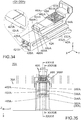
- a connector assembly 10 according to a first embodiment of the present invention comprises a mating connector 60 and a connector 20.
- the connector 20 and the mating connector 60 are mateable with each other.
- the connector assembly 10 has a connector position assurance (CPA) mechanism and a high-voltage interlock loop (HVIL) mechanism.
- the CPA mechanism locks a mated state where the connector 20 and the mating connector 60 are mated with each other.
- the HVIL mechanism is for preventing electric shock which might be caused by high-voltage power.
- the mating connector 60 of the present embodiment is configured to be mounted on a circuit board (not shown).
- the mating connector 60 comprises a mating housing 70, first mating terminals 82 and second mating terminals 84.
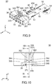
- the mating housing 70 of the present embodiment holds the first mating terminals 82 and the second mating terminals 84. As shown in Fig. 14 , the mating housing 70 forms a receiving portion 62.
- the receiving portion 62 of the present embodiment is a space which extends in a front-rear direction.
- the front-rear direction of the present embodiment is the X-direction.
- a mating direction which will be described later is the positive X-direction. Forward is the positive X-direction, and rearward is the negative X-direction.
- the mating housing 70 has an upper plate 72 and a rear plate 78.
- the upper plate 72 of the present embodiment defines one of opposite ends of the mating housing 70 in a perpendicular direction perpendicular to the mating direction.
- the perpendicular direction of the present embodiment is the Z-direction.
- the perpendicular direction is also an upper-lower direction. Upward is the positive Z-direction, and downward is the negative Z-direction.
- the upper plate 72 defines an upper end of the mating housing 70 in the upper-lower direction.
- the rear plate 78 of the present embodiment defines a front end of the mating housing 70 in the front-rear direction.
- the receiving portion 62 is located rearward of the rear plate 78 in the front-rear direction.
- the mating housing 70 is formed with a release projection 722, an extension portion 728, two lock holes 724 and two mating lock portions 725.
- the present invention is not limited thereto, but each of the number of the lock holes 724 and the number of the mating lock portions 725 may be one.
- the release projection 722 of the present embodiment projects into the receiving portion 62.
- the release projection 722 projects downward from the upper plate 72.
- the release projection 722 has a front surface 7222 and a rear surface 7224.
- the front surface 7222 of the present embodiment intersects with the front-rear direction.
- the front surface 7222 faces forward and downward.
- the front surface 7222 slopes rearward and downward.
- the rear surface 7224 of the present embodiment intersects with the front-rear direction.
- the rear surface 7224 faces rearward and downward.
- the rear surface 7224 slopes rearward and upward.
- the rear surface 7224 is located rearward of the front surface 7222 in the front-rear direction.
- the extension portion 728 of the present embodiment is located rearward of the rear plate 78 in the front-rear direction.
- the extension portion 728 is located forward of the release projection 722 in the front-rear direction.
- the extension portion 728 couples the rear plate 78 and the release projection 722 to each other in the front-rear direction.
- the extension portion 728 has a lower end which is located above a lower end of the release projection 722.
- each of the lock holes 724 of the present embodiment passes through the upper plate 72 in the upper-lower direction.
- Each of the lock holes 724 has an inner surface which faces forward in the front-rear direction.
- Each of the inner surfaces of the lock holes 724 works as the mating lock portion 725.
- each of the mating lock portions 725 of the present embodiment faces the receiving portion 62.
- Each of the mating lock portions 725 is a plane which faces forward in the front-rear direction.
- each of the first mating terminals 82 of the present embodiment is made of metal and has an L-like shape.
- Each of the first mating terminals 82 is a so-called pin contact.
- Each of the first mating terminals 82 has a lower end which is configured to be fixed and connected to a pad (not shown) of the circuit board via soldering, etc.
- each of the second mating terminals 84 of the present embodiment is made of metal and has an L-like shape.
- Each of the second mating terminals 84 is a so-called pin contact.
- Each of the second mating terminals 84 has a lower end which is configured to be fixed and connected to a pad (not shown) of the circuit board via soldering, etc.
- the connector 20 of the present embodiment is mateable with the mating connector 60 along the mating direction.
- the connector 20, which is mated with the mating connector 60, is removable from the mating connector 60 along a removing direction (negative X-direction) which is opposite to the mating direction (positive X-direction).
- the connector 20 of the present embodiment comprises a first housing 30, a plurality of first terminals 52, a second housing 40 and two second terminals 54.
- the first housing 30 of the present embodiment is configured to be received into the receiving portion 62 along the mating direction.
- the first housing 30 holds the first terminals 52.
- the first housing 30 has a mirror-symmetrical shape with respect to a plane which is perpendicular to a lateral direction and passes the middle of the first housing 30 in the lateral direction.
- the lateral direction of the present embodiment is the Y-direction.
- the first housing 30 is provided with an upper portion 305, stoppers 350, a first structure 36, an accommodation portion 33, an additional stopper 34, a partition wall 320 and a support-portion accommodation portion 325.
- the upper portion 305 of the present embodiment extends in the front-rear direction.
- the upper portion 305 has a lower surface 306 and projecting portions 307.
- the lower surface 306 is a plane which faces downward in the upper-lower direction.
- Each of the projecting portions 307 projects downward from the lower surface 306.
- Each of the projecting portions 307 is located at the middle of the first housing 30 in the front-rear direction.
- Each of the projecting portions 307 has a rear surface which faces rearward in the front-rear direction. The rear surface of each of the projecting portions 307 works as the stopper 350.
- each of the stoppers 350 of the present embodiment intersects with the front-rear direction.
- Each of the stoppers 350 is a plane which faces rearward in the front-rear direction.
- the first structure 36 of the present embodiment includes two first support portions 362, two lock portions 365 and a first operation portion (operation portion) 368.
- the first housing 30 is provided with the stoppers 350 and the first structure 36 which includes the first support portions 362 and the lock portions 365.
- the present invention is not limited thereto.
- the first structure 36 may include only one of the first support portions 362 and only one of the lock portions 365.
- each of the first support portions 362 of the present embodiment extends rearward in the front-rear direction from the upper portion 305.
- Each of the first support portions 362 has a restoring force and supports one of the lock portions 365.
- Each of the first support portions 362 is resiliently deformable in the perpendicular direction, i.e. in the upper-lower direction.
- Each of the first support portions 362 has a lock projection 364.
- each of the first support portions 362 of the present embodiment has the restoring force which is a resilient force thereof.
- the restoring force of each of the first support portions 362 of the present invention is not limited to the resilient force of the first support portion 362 itself.
- each of the first support portions 362 may be supported by a spring (not shown) separable from the first housing 30 to be turnable about a fulcrum which is a front end of the first support portion 362.
- each of the first support portions 362 may have a restoring force caused by another member.
- the modification as described above is applicable to each portion having a restoring force and each member having a restoring force in the present embodiment and in a second embodiment described later.
- the lock projections 364 of the present embodiment are located at the middle of the first structure 36 in the front-rear direction. Each of the lock projections 364 projects upward in the upper-lower direction. Each of the lock projections 364 has a rear surface which faces rearward in the front-rear direction. Each of the rear surfaces of the lock projections 364 works as the lock portion 365.
- each of the lock portions 365 of the present embodiment intersects with the front-rear direction.
- Each of the lock portions 365 is a plane which faces rearward in the front-rear direction.
- the lock portions 365 are provided on the first support portions 362, respectively.
- each of the first support portions 362 has the restoring force. Therefore, each of the lock portions 365 is movable in the perpendicular direction perpendicular to the mating direction by using the restoring force of the first support portion 362. More specifically, each of the lock portions 365 is movable in the upper-lower direction by using the restoring force of the first support portion 362.
- the lock portions 365 and the mating lock portions 725 lock a state where the first housing 30 is received in the receiving portion 62 when the first terminals 52 illustrated in Fig. 8 are connected to the first mating terminals 82.
- the first operation portion 368 of the present embodiment is located at a rear end of the first structure 36 in the front-rear direction.
- the first operation portion 368 is located in the vicinity of a rear end of the first housing 30 in the front-rear direction.
- the first operation portion 368 is located rearward of the first support portions 362 in the front-rear direction.
- the first operation portion 368 is located rearward of the lock portions 365 in the front-rear direction.
- the first support portions 362 can be resiliently deformed so that the lock portions 365 are moved inward of the first housing 30 in the perpendicular direction.
- each of the first support portions 362 has the restoring force. Therefore, when the aforementioned pressure against the first operation portion 368 is stopped, the first support portions 362 return to their initial shapes so that the lock portions 365 are moved outward of the first housing 30 in the perpendicular direction. More specifically, by pressing the first operation portion 368 downward, the first support portions 362 can be resiliently deformed so that the lock portions 365 are moved downward. When the aforementioned pressure against the first operation portion 368 is stopped, the first support portions 362 return to their initial shapes so that the lock portions 365 are moved upward.
- the accommodation portion 33 of the present embodiment is a hole which passes through the first housing 30 in the front-rear direction.
- the accommodation portion 33 is located below the lower surface 306 of the upper portion 305 in the upper-lower direction.
- the accommodation portion 33 is located below the first support portions 362 in the upper-lower direction.
- the accommodation portion 33 is located below the lock portions 365 in the upper-lower direction.
- the accommodation portion 33 is located below the first operation portion 368 in the upper-lower direction.
- the accommodation portion 33 is located at the middle of the first housing 30 in the lateral direction.
- the additional stopper 34 of the present embodiment is located at the middle of the first housing 30 in the front-rear direction.
- the additional stopper 34 is located in the vicinity of a lower end of the first housing 30.
- the additional stopper 34 is located in the accommodation portion 33 and projects upward in the upper-lower direction.
- the additional stopper 34 has a front surface 342 and a rear surface 344. Each of the front surface 342 and the rear surface 344 intersects with the front-rear direction.
- the front surface 342 faces forward in the front-rear direction.
- the rear surface 344 faces rearward and upward.
- the rear surface 344 slopes rearward and downward.
- the rear surface 344 is located rearward of the front surface 342 in the front-rear direction.
- the partition wall 320 of the present embodiment extends rearward from a front end of the first housing 30.
- the partition wall 320 is located below the lower surface 306 of the upper portion 305.
- the partition wall 320 is located forward of the first support portions 362 in the front-rear direction.
- the partition wall 320 is located forward of the lock portions 365 in the front-rear direction.
- the partition wall 320 is located forward of the first operation portion 368 in the front-rear direction.
- the partition wall 320 is located at the middle of the first housing 30 in the lateral direction.
- the support-portion accommodation portion 325 of the present embodiment is a space which extends in in the front-rear direction.
- the support-portion accommodation portion 325 is located at the middle of the first housing 30 in the lateral direction.
- the support-portion accommodation portion 325 is located between the two first support portions 362 in the lateral direction.
- the support-portion accommodation portion 325 is located between the two lock portions 365 in the lateral direction.
- the support-portion accommodation portion 325 is located forward of the first operation portion 368 in the front-rear direction.
- the support-portion accommodation portion 325 is located above the partition wall 320 in the upper-lower direction.
- the support-portion accommodation portion 325 has a main accommodation portion 326 and two additional accommodation portions 327.
- the main accommodation portion 326 of the present embodiment is a channel which extends in the front-rear direction.
- the main accommodation portion 326 is located at the middle of the first housing 30 in the lateral direction.
- the main accommodation portion 326 is located between the two first support portions 362 in the lateral direction.
- the main accommodation portion 326 is located between the two lock portions 365 in the lateral direction.
- the main accommodation portion 326 communicates with the outside of the first housing 30 in the upper-lower direction.
- the main accommodation portion 326 communicates with the outside of the first housing 30 in the front-rear direction.
- the main accommodation portion 326 is located forward of the first operation portion 368 in the front-rear direction.
- the main accommodation portion 326 is located between the two additional accommodation portions 327 in the lateral direction.
- the main accommodation portion 326 communicates with each of the additional accommodation portions 327 in the lateral direction.
- each of the additional accommodation portions 327 of the present embodiment is a space which extends in the front-rear direction.
- Each of the additional accommodation portions 327 communicates with the outside of the first housing 30 in the front-rear direction.
- the additional accommodation portions 327 are located below the lock portions 365 in the upper-lower direction, respectively.
- the additional accommodation portions 327 are located below the lower surface 306 of the upper portion 305 in the upper-lower direction.
- the first housing 30 further has additional locked portions 370.
- each of the additional locked portions 370 of the present embodiment is located in the vicinity of the rear end of the first housing 30 in the front-rear direction.
- Each of the additional locked portions 370 intersects with the front-rear direction. More specifically, each of the additional locked portions 370 is a plane which faces forward in the front-rear direction.
- Each of the additional locked portions 370 is located rearward of the first operation portion 368 in the front-rear direction.
- each of the first terminals 52 of the present embodiment is made of metal.
- Each of the first terminals 52 is a so-called socket contact and is connected to a cable 56.
- the first terminals 52 are connected to the first mating terminals 82, respectively, when the first housing 30 is received in the receiving portion 62.
- Each of the first terminal 52 and the corresponding first mating terminal 82 are configured to be connected to each other to transmit high-voltage current.
- the second housing 40 of the present embodiment is held by the first housing 30 to be movable relative to the first housing 30.
- the second housing 40 holds the second terminals 54.
- the second housing 40 is provided with a body portion 42, a head portion 44, a regulation portion 442, a second support portion 46, two stopped portions 464, two additional support portions 45, two additional lock portions 454, two second operation portions 458 and an additional stopped portion 424.
- the second support portion 46 is provided to the second housing 40.
- the present invention is not limited thereto, but the second support portion 46 may be provided to the first housing 30. In other words, one of the first housing 30 and the second housing 40 should be provided with the second support portion 46.
- the second support portion 46 is preferred to be provided to the second housing 40 for more flexible design of the connector 20.
- the body portion 42 of the present embodiment has a rectangular cylindrical shape which extends in the front-rear direction.
- the body portion 42 has an upper surface 423 which faces upward.
- the head portion 44 of the present embodiment is located above the body portion 42 in the upper-lower direction.
- the head portion 44 is provided on the upper surface 423 of the body portion 42.
- the head portion 44 defines an upper end of the second housing 40 in the upper-lower direction.
- the regulation portion 442 of the present embodiment has a plate-like shape. As shown in Fig. 5 , the regulation portion 442 extends forward from the head portion 44 in the front-rear direction. The regulation portion 442 is located in the vicinity of an upper end of the head portion 44. The regulation portion 442 is apart from and is located above the body portion 42 in the upper-lower direction. The regulation portion 442 is apart from and is located above the second support portion 46 in the upper-lower direction.
- the second support portion 46 of the present embodiment has a restoring force and supports each of the stopped portions 464 as the supported portion 464.
- the second support portion 46 is resiliently deformable in the perpendicular direction, i.e. in the upper-lower direction.
- the present invention is not limited thereto.
- the second support portion 46 may support each of the stoppers 350 of the first housing 30 as a supported portion.
- the second support portion 46 should have the restoring force and should support the supported portions each of which is one of the stopper 350 and the stopped portion 464.
- the second support portion 46 has a protrusion support portion 465, a protrusion 466 and two stopped-portion support portions 462.
- the protrusion support portion 465 of the present embodiment has a restoring force and extends forward from the middle of the upper surface 423 of the body portion 42 in the front-rear direction.
- the protrusion support portion 465 is located at the middle of the second support portion 46 in the lateral direction.
- the protrusion support portion 465 is sandwiched by the two stopped-portion support portions 462 in the lateral direction.
- the protrusion support portion 465 is coupled to each of the stopped-portion support portions 462 in the lateral direction.
- the protrusion 466 of the present embodiment is movable in the perpendicular direction, i.e. in the upper-lower direction, by using the restoring force of the second support portion 46.
- the protrusion 466 is located rearward of a front end of the body portion 42 in the front-rear direction.
- the protrusion 466 is located forward of the stopped portions 464 in the front-rear direction.
- the protrusion 466 is located at a front end of the second support portion 46 in the front-rear direction.
- the protrusion 466 is located at a front end of the protrusion support portion 465 in the front-rear direction.
- the protrusion 466 is sandwiched by the two stopped portions 464 in the lateral direction.
- the protrusion 466 is coupled to each of the stopped portions 464 in the lateral direction. As shown in Fig. 5 , the protrusion 466 projects upward in the upper-lower direction. The protrusion 466 is located below the regulation portion 442 in the upper-lower direction.
- the protrusion 466 of the present embodiment has a front surface 467 and a rear surface 468.
- the front surface 467 of the present embodiment intersects with the front-rear direction.
- the front surface 467 faces forward and upward.
- the front surface 467 slopes rearward and upward.
- the rear surface 468 of the present embodiment intersects with the front-rear direction.
- the rear surface 468 faces rearward and upward.
- the rear surface 468 slopes rearward and downward.
- the rear surface 468 is located rearward of the front surface 467 in the front-rear direction.
- each of the stopped-portion support portions 462 of the present embodiment has a restoring force and extends forward from the middle of the upper surface 423 of the body portion 42 in the front-rear direction.
- the stopped-portion support portions 462 are located at opposite sides of the second support portion 46 in the lateral direction, respectively.
- Each of the stopped-portion support portions 462 has an upper end 463 in the upper-lower direction.
- the stopped portions 464 of the present embodiment are provided to the second support portion 46.
- the second support portion 46 has the restoring force. Therefore, the stopped portions 464 are movable in the perpendicular direction, i.e. in the upper-lower direction, by using the restoring force of the second support portion 46.
- the supported portions 464 are movable in the perpendicular direction, i.e. in the upper-lower direction, by using the restoring force of the second support portion 46.
- Each of the stopped portions 464 intersects with the front-rear direction.
- Each of the stopped portions 464 is a plane which faces forward in the front-rear direction.
- Each of the stopped portions 464 faces forward in the front-rear direction.
- the stopped portions 464 are located rearward of the front end of the body portion 42 in the front-rear direction.
- the stopped portions 464 are located at front ends of the stopped-portion support portions 462 in the front-rear direction, respectively.
- the stopped portions 464 are located rearward of the protrusion 466 in the front-rear direction.
- the two stopped portions 464 sandwich the protrusion 466 in the lateral direction.
- each of the additional support portions 45 of the present embodiment has a restoring force.
- Each of the additional support portions 45 is resiliently deformable in the lateral direction.
- the additional support portions 45 are located above the body portion 42 in the upper-lower direction. As shown in Fig. 3 , the additional support portions 45 are located about opposite ends of the second housing 40 in the lateral direction, respectively.
- Each of the additional support portions 45 extends outward of the second housing 40 in the lateral direction from an outer end of the head portion 44 in the lateral direction.
- Each of the additional support portions 45 extends rearward from a front end of the head portion 44.
- the additional support portions 45 support the additional lock portions 454, respectively.
- the additional lock portions 454 of the present embodiment are located about the opposite ends of the second housing 40 in the lateral direction, respectively.
- Each of the additional lock portions 454 extends outward of the second housing 40 in the lateral direction from the additional support portion 45.
- Each of the additional lock portions 454 intersects with the front-rear direction.
- Each of the additional lock portions 454 is a plane which faces rearward in the front-rear direction.
- the second operation portions 458 of the present embodiment are located at the opposite ends of the second housing 40 in the lateral direction, respectively.
- the second operation portions 458 are located at a rear end of the second housing 40 in the front-rear direction.
- the second operation portions 458 are located rearward of the additional support portions 45 in the front-rear direction, respectively.
- the second operation portions 458 are located rearward of the additional lock portions 454 in the front-rear direction, respectively.
- the additional stopped portion 424 of the present embodiment projects downward from a part of the body portion 42 which is located at a lower end and a front end of the body portion 42.
- the additional stopped portion 424 has a front surface 425 and a rear surface 426.
- Each of the front surface 425 and the rear surface 426 intersects with the front-rear direction.
- the front surface 425 faces forward and downward.
- the front surface 425 slopes rearward and downward.
- the rear surface 426 faces rearward in the front-rear direction.
- the rear surface 426 is located rearward of the front surface 425 in the front-rear direction.
- each of the second terminals 54 of the present embodiment is made of metal.
- Each of the second terminals 54 is a so-called socket contact and is connected to a cable 58.
- the two second terminals 54 of the present embodiment are not short-circuited.
- the present invention is not limited thereto, but the two second terminals 54 may be short-circuited by a cable 59 as shown in a dashed circle of Fig. 9 .
- the number of the second terminals 54 may be two, and the two second terminals 54 may be connected to each other.
- the second terminals 54 are accommodated in the body portion 42.
- the second terminals 54 and the second mating terminals 84 are configured to be connected to an HVIL circuit (not shown) and to control the opening and the closing of the HVIL circuit. More specifically, when the second terminals 54 are connected to the second mating terminals 84, respectively, the HVIL circuit is closed, and electric current flows between the first terminals 52 illustrated in Fig. 8 and the first mating terminals 82 illustrated in Fig. 18 . When the second terminals 54 are disconnected from the second mating terminals 84, respectively, the HVIL circuit is opened, and electric power supply between the first terminals 52 illustrated in Fig. 8 and the first mating terminals 82 illustrated in Fig. 18 is stopped. Thus, the connector assembly 10 has the HVIL mechanism which includes the second terminals 54, the second mating terminals 84 and the HVIL circuit.
- the second housing 40 is installed to the first housing 30 along the mating direction.
- the first housing 30 and the second housing 40 are arranged so that the body portion 42 of the second housing 40 is located rearward of the accommodation portion 33 of the first housing 30.
- the second housing 40 is moved forward relative to the first housing 30 so that the body portion 42 of the second housing 40 is accommodated in the accommodation portion 33 of the first housing 30.
- the front surface 425 of the additional stopped portion 424 of the second housing 40 is brought into contact with the rear surface 344 of the additional stopper 34 located in the accommodation portion 33 of the first housing 30.
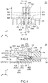
- the additional stopped portion 424 of the second housing 40 rides over the additional stopper 34 of the first housing 30, and the rear surface 426 of the additional stopped portion 424 faces the front surface 342 of the additional stopper 34 in the front-rear direction. Thereafter, the stopped portions 464 of the second housing 40 are brought into abutment with the stoppers 350 of the first housing 30, respectively, and the connector 20 takes a regulated state shown in Fig. 4 .
- the stopped portions 464 are in abutment with the stoppers 350, respectively, and a movement of the second housing 40 in the mating direction is regulated by the stoppers 350.
- the stopped portions 464 are brought into abutment with the stoppers 350 from behind, and a forward movement of the second housing 40 in the front-rear direction is regulated by the stoppers 350.
- a rearward movement of the second housing 40 in the front-rear direction is also regulated.
- the additional stopper 34 regulates a movement of the additional stopped portion 424 in the removing direction so that the second housing 40 is unremovable from the first housing 30.
- the aforementioned mechanism regulates both of the forward movement and the rearward movement of the second housing 40 relative to the first housing 30 in the front-rear direction.
- the stopped portions 464 are brought into abutment with the stoppers 350, and the second housing 40 takes the regulated state where the movement of the second housing 40 in the mating direction is regulated by the stoppers 350.
- the connector 20 is arranged to face the mating connector 60 along the mating direction while the second housing 40 thereof takes the regulated state. Thereafter, the connector 20 and the mating connector 60 are moved to be closer to each other in the mating direction, and the first housing 30 is received into the receiving portion 62. During this operation, the first terminals 52 illustrated in Fig. 8 are connected to the first mating terminals 82, respectively, and then the front surface 467 of the protrusion 466 of the second housing 40 of the connector 20 is brought into contact with the rear surface 7224 of the release projection 722 of the mating connector 60.
- the connector 20 and the mating connector 60 are moved to be further close to each other in the mating direction after they take a state where the front surface 467 of the protrusion 466 is in contact with the rear surface 7224 of the release projection 722.
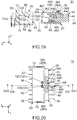
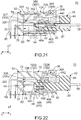
- the second support portion 46 is resiliently deformed so that the protrusion 466 is pushed down by the release projection 722, and the connector 20 and the mating connector 60 take a state shown in Figs. 20 to 22 .
- the first terminals 52 are connected to the first mating terminals 82, and then the second support portion 46 is brought into abutment with the release projection 722 so that the movement regulation of the second housing 40 in the mating direction is released.
- the lock projections 364 of the connector 20 are accommodated in the lock holes 724 of the mating connector 60, respectively, and the lock portions 365 face the mating lock portions 725 in the front-rear direction, respectively.
- the lock portions 365 and the mating lock portions 725 lock a state where the first housing 30 is received in the receiving portion 62.
- the connector assembly 10 takes a state shown in Figs. 23 to 25 .
- the second support portion 46 is accommodated in the support-portion accommodation portion 325 and returns to its initial shape.
- the stopped portions 464 and the stopped-portion support portions 462 are accommodated in the additional accommodation portions 327, and the protrusion 466 and the protrusion support portion 465 are accommodated in the main accommodation portion 326.
- an upper end of the protrusion 466 is not in contact with the lower end of the extension portion 728, and a lower end of the protrusion 466 is not in contact with the partition wall 320.
- the protrusion support portion 465 is not in contact with the release projection 722.
- the second terminals 54 of the connector 20 are connected to the second mating terminals 84 of the mating connector 60, respectively, so that the HVIL circuit is closed, and the electric current flows between the first terminals 52 illustrated in Fig. 8 and the first mating terminals 82 illustrated in Fig. 18 .
- the regulation portion 442 is moved inward of the first operation portion 368 in the perpendicular direction to regulate a movement of the lock portions 365 in the perpendicular direction. More specifically, under this state, the regulation portion 442 is located below the first operation portion 368 in the upper-lower direction to regulate a downward movement of the lock portions 365.
- the second terminals 54 are connected to the second mating terminals 84, and the regulation portion 442 is located inward of the first operation portion 368 in the perpendicular direction to regulate the movement of the lock portions 365 in the perpendicular direction.
- the regulation portion 442 may be located inward of at least a part of the first structure 36 in the perpendicular direction to regulate the movement of the lock portions 365 in the perpendicular direction.
- the second terminals 54 may be connected to the second mating terminals 84, and the regulation portion 442 may be located inward of at least a part of the first structure 36 in the perpendicular direction to regulate the movement of the lock portions 365 in the perpendicular direction.
- the connector assembly 10 has the CPA mechanism which locks the mated state of the connector 20 with the mating connector 60.
- the additional lock portions 454 face the additional locked portions 370 in the front-rear direction, respectively.
- the additional lock portions 454 and the additional locked portions 370 lock the state where the second housing 40 is installed to the first housing 30.
- the second housing 40 is moved rearward to be away from the first housing 30 while the aforementioned pressed state of the second operation portions 458 is kept. At the end of this operation, the rear surface 468 of the protrusion 466 of the second housing 40 of the connector 20 is brought into contact with the front surface 7222 of the release projection 722 of the mating connector 60.
- the second housing 40 is further moved rearward to be away from the first housing 30 after they take a state where the rear surface 468 of the protrusion 466 is in contact with the front surface 7222 of the release projection 722.
- the second support portion 46 is resiliently deformed so that the protrusion 466 is pushed down by the release projection 722, and the second housing 40 and the first housing 30 take a state shown in Figs. 20 to 22 .
- the second terminals 54 are disconnected from the second mating terminals 84.
- the HVIL circuit is opened, and the electric power supply between the first terminals 52 illustrated in Fig. 8 and the first mating terminals 82 illustrated in Fig. 18 is stopped.
- the regulation portion 442 is located rearward of the first operation portion 368 in the front-rear direction.
- the first operation portion 368 is pressed inward of the first housing 30 in the perpendicular direction, the first operation portion 368 is not brought into abutment with the regulation portion 442.
- the first operation portion 368 is pressed inward of the first housing 30 in the perpendicular direction, i.e. downward.
- the lock portions 365 are moved downward relative to the mating lock portions 725, the lock of the state, in which the first housing 30 is received in the receiving portion 62, is released.
- the connector 20 is moved rearward to be away from the mating connector 60 while the aforementioned pressed state of the first operation portion 368 is kept. As a result, the connector 20 can be removed from the mating connector 60, and the mated state of the connector 20 with the mating connector 60 can be released.
- the mating connector 60 of the present embodiment comprises the first mating terminals 82 and the second mating terminals 84 configured to be connected to the pads of the circuit board.
- the mating connector 60 may comprise the terminals for cables, each of which is configured to be connected to a cable, instead of the first mating terminals 82 and the second mating terminals 84.
- the connector assembly 10 may be used as a relay connector comprising the connector 20 and the mating connector 60 each of which forms a cable harness.
- the mating lock portions 725 are the inner surfaces of the lock holes 724, and the lock portions 365 are the rear surfaces of the lock projections 364.
- each of the mating lock portions 725 may be a front surface of a projection which projects downward from the upper plate 72.
- Each of the lock portions 365 may be an inner surface of a hole which passes through the first support portion 362 in the upper-lower direction, and each of the inner surfaces may face rearward.
- the connector assembly 10 of the present embodiment when the second housing 40 under the aforementioned regulated state is received into the receiving portion 62 of the mating connector 60 along the mating direction together with the first housing 30, the protrusion 466 of the second support portion 46 is brought into abutment with the release projection 722 so that the aforementioned movement regulation is released.
- the present invention is not limited thereto.
- the supported portions 464 may be brought into abutment with the release projection 722 so that the movement regulation is released.
- the first terminals 52 should be connected to the first mating terminals 82, and then one of the second support portion 46 and the supported portion 464 should be brought into abutment with the release projection 722 so that the movement regulation is released.
- the present invention is not limited to the aforementioned first embodiment but can be variously applicable.
- specific explanation will be made about the second embodiment of the present invention. This specific explanation includes description about structures and modifications which are not specifically described in the first embodiment.
- a connector assembly 10A according to the second embodiment of the present invention comprises a connector 20A and a mating connector 60A.
- the connector 20A is mateable with the mating connector 60A along a mating direction (positive X-direction).
- the connector 20A which is mated with the mating connector 60A, is removable from the mating connector 60A along a removing direction opposite to the mating direction.
- the mating direction of the present embodiment is the positive X-direction directed forward in a front-rear direction (X-direction).
- the removing direction of the present embodiment is the negative X-direction directed rearward in the front-rear direction (X-direction).
- the connector 20A of the present embodiment is a cable connector which is connected to cables 56A and 58A.
- the connector 20A forms a cable harness together with the cables 56A and 58A.
- the mating connector 60A of the present embodiment is an on-board connector which is mounted on a circuit board (not shown).
- the present invention is not limited thereto but is applicable to various connector assemblies comprising various connectors and mating connectors.
- the mating connector 60A may be connected to cables to from a cable harness similarly to the connector 20A.
- the cables 56A and 58A of the present embodiment are connected to a power device (not shown).
- the circuit board (not shown) on which the mating connector 60A is mounted is installed in a mating electronic device (not shown).
- the mating electronic device Under a mated state where the connector 20A and the mating connector 60A are mated with each other, the mating electronic device is electrically connected with the power device, and the power device supplies high-voltage power to the mating electronic device.
- the connector assembly 10A has a connector position assurance mechanism (CPA mechanism) which locks the mated state and a high-voltage interlock loop mechanism (HVIL mechanism) for preventing electric shock which might be caused by the high-voltage power.
- CCA mechanism connector position assurance mechanism
- HVIL mechanism high-voltage interlock loop mechanism
- the mating connector 60A of the present embodiment comprises a mating housing 70A made of insulator, two additional members 64A made of metal, a plurality of first mating terminals 82A each made of conductor and a plurality of second mating terminals 84A each made of conductor.
- the first mating terminals 82A of the present embodiment are terminals for supplying electric power.
- the second mating terminals 84A of the present embodiment are parts of the HVIL mechanism.
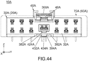
- the mating connector 60A of the present embodiment is provided with six pairs of the first mating terminals 82A, i.e. twelve of the first mating terminals 82A, and a pair of the second mating terminals 84A, i.e. two of the second mating terminals 84A.
- the present invention is not limited thereto.
- the number of the first mating terminals 82A may be designed in accordance with usage.
- the number of the second mating terminals 84A may be designed in accordance with a necessary HVIL mechanism.
- the second mating terminals 84A do not need to be provided.
- the HVIL mechanism may be formed of members different from the second mating terminals 84A.
- the additional members 64A may be provided as necessary.
- the mating connector 60A of the present invention should comprise the mating housing 70A and one or more of the first mating terminals 82A.
- the mating connector 60A may further comprise another member in addition to the aforementioned members.
- the mating housing 70A of the present embodiment has an upper plate 72A, two side plates 74A, a bottom plate 76A and a rear plate 78A.
- Each of the upper plate 72A, the side plates 74A, the bottom plate 76A and the rear plate 78A has a rectangular flat-plate shape.
- the upper plate 72A, the side plates 74A, the bottom plate 76A and the rear plate 78A are connected to each other to form a rectangular parallelepiped box which opens rearward.
- the upper plate 72A is located at an upper end of the mating housing 70A in a perpendicular direction (upper-lower direction: Z-direction) perpendicular to the X-direction and extends along a horizontal plane (XY-plane) perpendicular to the Z-direction.
- the bottom plate 76A is located at a lower end of the mating housing 70A and extends along the XY-plane in parallel to the upper plate 72A.
- the two side plates 74A are located at opposite sides of the mating housing 70A, respectively, in a lateral direction (Y-direction) perpendicular to both the X-direction and the Z-direction and extend along a predetermined plane (XZ-plane) in parallel to each other.
- the rear plate 78A extends along a perpendicular plane (YZ-plane) and is connected to front ends (positive X-side ends) of the upper plate 72A, the side plates 74A and the bottom plate 76A.
- the mating housing 70A which is formed as described above has a receiving portion 62A in which the connector 20A is receivable.
- the mating housing 70A forms the receiving portion 62A of the mating connector 60A.
- the receiving portion 62A of the present embodiment is a rectangular parallelepiped space which is enclosed by the upper plate 72A, the side plates 74A, the bottom plate 76A and the rear plate 78A and opens rearward.
- the rear plate 78A defines a front end of the receiving portion 62A.
- the mating housing 70A of the present embodiment has the aforementioned structure as a whole.
- the structure of the mating housing 70A is not limited to the present embodiment, provided that the mating connector 60A is provided with the receiving portion 62A.
- the mating housing 70A is formed with a release projection 722A and two mating lock portions (lock holes) 724A.
- the release projection 722A and the mating lock portions 724A are parts of the CPA mechanism of the connector assembly 10A.
- the number of the release projection 722A is one, and the number of the mating lock portions 724A is two.
- the two mating lock portions 724A are arranged in the Y-direction while the release projection 722A is located therebetween.
- the number of the release projection 722A and the number of the mating lock portions 724A may be designed in accordance with a necessary CPA mechanism.
- the release projection 722A and the mating lock portions 724A may be arranged in accordance with a necessary CPA mechanism.
- the release projection 722A of the present embodiment is provided on the upper plate 72A.
- the release projection 722A is located at a rear end (negative X-side end) of the upper plate 72A in the X-direction and is located at the middle of the upper plate 72A in the Y-direction.
- the release projection 722A projects downward, i.e. in the negative Z-direction, from a lower surface (negative Z-side surface) of the upper plate 72A.
- the release projection 722A of the present embodiment has a rear end formed with a guide surface and a front end formed with a stop surface.
- the guide surface of the release projection 722A is a gentle slope which relatively gently slopes forward and downward.
- the stop surface of the release projection 722A is a sharp slope which sharply slopes forward and downward.
- the structure of the release projection 722A is not limited to the present embodiment but can be modified as necessary, provided that the release projection 722A is, at least in part, located in the receiving portion 62A.
- the mating lock portions 724A of the present embodiment are formed in the upper plate 72A.
- Each of the mating lock portions 724A is a hole formed in the upper plate 72A and has a rectangular shape in the XY-plane.
- Each of the mating lock portions 724A passes through the upper plate 72A in the Z-direction to communicates with the receiving portion 62A.
- each of the mating lock portions 724A faces the receiving portion 62A.
- Each of the mating lock portions 724A of the present embodiment has the aforementioned structure.
- the structure of each of the mating lock portions 724A can be variously modified, provided that each of the mating lock portions 724A faces the inner space of the receiving portion 62A.
- each of the mating lock portions 724A may be a projection instead of a hole. When each of the mating lock portions 724A is a projection, each of the mating lock portions 724A may project into the receiving portion 62A.
- the mating housing 70A holds the first mating terminals 82A and the second mating terminals 84A.
- the first mating terminals 82A and the second mating terminals 84A of the present embodiment are insert-molded into and are held by the rear plate 78A of the mating housing 70A.
- the present invention is not limited thereto, but the first mating terminals 82A and the second mating terminals 84A may be held by the mating housing 70A in any manner.
- the second mating terminals 84A are located at the middle of the rear plate 78A in the Y-direction and are arranged in the Y-direction.
- the first mating terminals 82A are divided into two rows in the Z-direction.
- the first mating terminals 82A of each row are arranged in the Y-direction so that the second mating terminals 84A are located between two of the first mating terminals 82A.
- the first mating terminals 82A and the second mating terminals 84A of the present embodiment are arranged as described above. However, the arrangement of the first mating terminals 82A and the second mating terminals 84A is not limited to the present embodiment.
- each of the first mating terminals 82A is a so-called pin contact which is formed by bending a metal rod.
- Each of the first mating terminals 82A has a mating contact portion 822A and a mating fixed portion 828A.
- Each of the mating contact portions 822A is located within the receiving portion 62A.
- the mating contact portions 822A extend from the rear plate 78A toward the opening of the receiving portion 62A along the negative X-direction and extend to positions same as each other.
- Each of the mating fixed portions 828A projects outward of the mating housing 70Afrom the rear plate 78A and extends downward as a whole.
- Each of the mating fixed portions 828A is fixed and connected to the circuit board (not shown) via soldering, etc. when the mating connector 60A is used.
- Each of the second mating terminals 84A is a so-called pin contact which is formed by bending a metal rod.
- Each of the second mating terminals 84A has a mating contact portion 842A and a mating fixed portion 848A.
- Each of the mating contact portions 842A is located within the receiving portion 62A.
- the mating contact portion 842A extend from the rear plate 78A toward the opening of the receiving portion 62A along the negative X-direction and extend to positions same as each other.
- Each of the mating fixed portions 848A projects outward of the mating housing 70Afrom the rear plate 78A and extends downward as a whole.
- Each of the mating fixed portions 848A is fixed and connected to the circuit board (not shown) via soldering, etc. when the mating connector 60A is used.
- the mating contact portions 842A of the second mating terminals 84A extend along the negative X-direction to the position which is same as the position to which the mating contact portions 822A of the first mating terminals 82A extend. In other words, the position of rear ends of the mating contact portions 822A in the X-direction is same as the position of rear ends of the mating contact portions 842A in the X-direction.
- Each of the first mating terminals 82A and the second mating terminals 84A of the present embodiment has the aforementioned structure. However, the structure of each of the first mating terminals 82A and the second mating terminals 84A is not limited to the present embodiment.
- the connector 20A of the present embodiment comprises a first housing 30A made of insulator, a second housing 40A made of insulator, a plurality of first terminals 52A each made of conductor and a plurality of second terminals 54A each made of conductor.
- the first terminals 52A of the present embodiment are terminals for supplying electric power.
- the first terminals 52A are connected to the cables 56A for supplying electric power, respectively, when the connector 20A is used.
- the second terminals 54A are parts of the HVIL mechanism.
- the second terminals 54A are connected to the cables 58A for transmitting signals, respectively, when the connector 20A is used.
- the first terminals 52A of the present embodiment correspond to the first mating terminals 82A (see Fig. 26 ), respectively.
- the second terminals 54A of the present embodiment correspond to the second mating terminals 84A, respectively.
- the connector 20A of the present embodiment is provided with six pairs of the first terminals 52A, i.e. twelve of the first terminals 52A and a pair of the second terminals 54A, i.e. two of the second terminals 54A.
- the connector 20A of the present embodiment has the aforementioned members.
- the present invention is not limited thereto.
- the number of the first terminals 52A may be designed in accordance with usage.
- the number of the second terminals 54A may be designed in accordance with a necessary HVIL mechanism. When no HVIL mechanism is provided, the second terminals 54A do not need to be provided.
- the HVIL mechanism may be formed of members different from the second terminals 54A.
- the connector 20A of the present invention should comprise the first housing 30A, the second housing 40A and one or more of the first terminals 52A.
- the connector 20A may comprise another member in addition to the aforementioned members.
- the first housing 30A is partially insertable into the receiving portion 62A of the mating connector 60A.
- the first housing 30A is inserted into the receiving portion 62A along the positive X-direction to be received in the receiving portion 62A.
- the first housing 30A is configured to be received into the receiving portion 62A along the positive X-direction.
- the first housing 30A of the present embodiment has a base portion 32A, a first structure 36A and an additional structure 38A.
- the base portion 32A has a shape which corresponds to the receiving portion 62A of the mating connector 60A.
- the first structure 36A is a part of the CPA mechanism of the connector assembly 10A.
- the first structure 36A of the present embodiment is connected to an upper side (positive Z-side) of the base portion 32A.
- the additional structure 38A is connected to a lower side (negative Z-side) of the base portion 32A.
- the first housing 30A of the present embodiment has the aforementioned structure as a whole. However, the structure of the first housing 30A can be modified as necessary.
- the base portion 32A is formed with an accommodation portion 33A and a plurality of first-terminal accommodation portions 35A.
- the accommodation portion 33A is a hole which passes through the base portion 32A in the X-direction and opens forward and rearward.
- the accommodation portion 33A has a rectangular parallelepiped shape.
- Each of the first-terminal accommodation portions 35A is a hole which passes through the base portion 32A in the X-direction and opens forward and rearward.
- the accommodation portion 33A is a space which accommodates a part of the second housing 40A but allows a movement of the second housing 40A.
- the accommodation portion 33A is located at the middle of the base portion 32A in the Y-direction.
- the accommodation portion 33A is provided with an upper wall 332A and a bottom wall 334A.
- the upper wall 332A is an upper inner wall of the accommodation portion 33A.
- the bottom wall 334A is a lower inner wall of the accommodation portion 33A.
- the bottom wall 334A is formed with an additional stopper 34A.
- the additional stopper 34A is a part for holding a part of the second housing 40A in the accommodation portion 33A.
- the additional stopper 34A projects upward, i.e. in the positive Z-direction, from the bottom wall 334A.
- the additional stopper 34A projects into the accommodation portion 33A.
- the additional stopper 34A of the present embodiment has a rear end formed with a guide surface and a front end formed with a stop surface.
- the guide surface of the additional stopper 34A is a gentle slope which relatively gently slopes forward and upward.
- the stop surface of the additional stopper 34A is a sharp slope which sharply slopes forward and upward.
- the accommodation portion 33A of the present embodiment has the aforementioned structure. However, the structure of the accommodation portion 33A is not limited to the present embodiment.
- the first-terminal accommodation portions 35A are provided so as to correspond to the first terminals 52A, respectively.
- Each of the first-terminal accommodation portions 35A is a space for accommodating the corresponding first terminal 52A.
- positions of the first-terminal accommodation portions 35A in the YZ-plane correspond to positions of the mating contact portions 822A of the first mating terminals 82A of the mating connector 60A in the YZ-plane, respectively.
- the first-terminal accommodation portions 35A are arranged so that the mating contact portions 822A can be received therein, respectively.
- each of the first terminals 52A is a so-called socket contact which is formed by bending a single metal plate.
- each of the first terminals 52A is a single metal plate with bends.
- the first terminals 52A of the present embodiment have shapes same as each other.
- Each of the first terminals 52A has a contact portion 522A and a connected portion 528A.
- each of the contact portions 522A can receive a part of the mating contact portion 822A of the corresponding first mating terminal 82A and thereby can be brought into contact with the mating contact portion 822A.
- the thus-formed first terminals 52A are connected to the first mating terminals 82A, respectively, when the first housing 30A is received in the receiving portion 62A of the mating connector 60A. Meanwhile, each of the connected portions 528A is connected to the corresponding cable 56A.
- Each of the first terminals 52A of the present embodiment has the aforementioned structure. However, the structure of each of the first terminals 52A is not limited to the present embodiment.
- each of the first terminals 52A is inserted into the corresponding first-terminal accommodation portion 35A together with an end of the cable 56A and is held therein to be unmovable relative to the base portion 32A.
- the first housing 30A holds the first terminals 52A.
- the contact portion 522A of each of the first terminals 52A is located in the vicinity of a front end of the base portion 32A.
- the second housing 40A is partially insertable in the accommodation portion 33A of the first housing 30A.
- the second housing 40A is inserted into the accommodation portion 33A from behind and is accommodated therein so that the connector 20A is assembled.
- the second housing 40A of the present embodiment has a body portion 42A, an additional structure 43A, a coupling portion 44A and a second structure 46A.
- the body portion 42A has a shape which corresponds to the accommodation portion 33A (see Fig. 32 ) of the first housing 30A (see Fig. 32 ).
- the additional structure 43A is connected to a lower surface of the body portion 42A and extends rearward beyond a rear end of the body portion 42A.
- the coupling portion 44A is connected to a rear end of an upper surface (positive Z-side surface) of the body portion 42A and extends upward from the upper surface of the body portion 42A.
- the second structure 46A is a part of the CPA mechanism of the connector assembly 10A (see Fig.
- the second structure 46A of the present embodiment is connected to an upper end of the coupling portion 44A. Most of the second structure 46A extends forward from the coupling portion 44A while a part of the second structure 46A protrudes rearward from the coupling portion 44A. Thus, the coupling portion 44A couples the second structure 46A to the body portion 42A.
- the second housing 40A of the present embodiment has the aforementioned structure as a whole. However, the structure of the second housing 40A can be modified as necessary.
- the body portion 42A of the present embodiment is formed with two second-terminal accommodation portions 428A and a bottom plate 422A which has an additional stopped portion 424A.
- the second housing 40A of the present embodiment is provided with the second-terminal accommodation portions 428A and the additional stopped portion 424A.
- each of the second-terminal accommodation portions 428A is a hole which passes through the body portion 42A in the X-direction and opens forward and rearward.
- the second-terminal accommodation portions 428A are provided so as to correspond to the second terminals 54A, respectively.
- Each of the second-terminal accommodation portions 428A is a space for accommodating the corresponding second terminal 54A.
- positions of the second-terminal accommodation portions 428A in the YZ-plane correspond to positions of the mating contact portions 842A of the second mating terminals 84A of the mating connector 60A in the YZ-plane, respectively.
- the second-terminal accommodation portions 428A are arranged so that the mating contact portions 842A can be received therein, respectively.
- the body portion 42A is formed with a recess 421A which is recessed rearward.
- the bottom plate 422A is a lower inner wall of the recess 421A.
- the bottom plate 422A has a thin thickness, i.e. a small size in the Z-direction. The thus-formed bottom plate 422A is easily bent.
- the additional stopped portion 424A is located at a front end of the bottom plate 422A and projects downward from a lower surface of the bottom plate 422A.
- the additional stopped portion 424A of the present embodiment has a front end formed with a guided surface and a rear end formed with a stopped surface.
- the guided surface of the additional stopped portion 424A is a gentle slope which relatively gently slopes rearward and downward.
- the stopped surface of the additional stopped portion 424A is a sharp slope which sharply slopes rearward and downward.
- the body portion 42A of the present embodiment has the aforementioned structure.
- the structure of the body portion 42A is not limited to the present embodiment.
- each of the second terminals 54A is a so-called socket contact which is formed by bending a single metal plate.
- each of the second terminals 54A is a single metal plate with bends.
- the second terminals 54A of the present embodiment have shapes same as each other.
- Each of the second terminals 54A has a contact portion 542A and a connected portion 548A.
- each of the contact portions 542A can receive a part of the mating contact portion 842A of the corresponding second mating terminal 84A and thereby can be brought into contact with the mating contact portion 842A.
- each of the connected portions 548A is connected to the corresponding cable 58A.
- the second terminals 54A are connected to the cables 58A, respectively.
- Each of the second terminals 54A of the present embodiment has the aforementioned structure. However, the structure of each of the second terminals 54A is not limited to the present embodiment.
- each of the second terminals 54A is inserted into the corresponding second-terminal accommodation portion 428A together with an end of the cable 58A and is held therein to be unmovable relative to the body portion 42A.
- the second housing 40A holds the second terminals 54A.
- the contact portion 542A of each of the second terminals 54A is located in the vicinity of a front end of the body portion 42A.
- the body portion 42A of the second housing 40A is inserted into the accommodation portion 33A of the first housing 30Afrom behind.
- the guided surface of the front end of the additional stopped portion 424A is guided by the guide surface of the rear end of the additional stopper 34A.
- the thus-guided additional stopped portion 424A is moved forward beyond the additional stopper 34A while the bottom plate 422A is bent.
- the additional stopped portion 424A is located forward of the additional stopper 34A and faces the additional stopper 34A in the X-direction.
- the stopped surface of the rear end of the additional stopped portion 424A is stopped by the stop surface of the front end of the additional stopper 34A so that the rearward movement of the second housing 40A is stopped.
- the additional stopper 34A and the additional stopped portion 424A are engaged with each other so that the body portion 42A of the second housing 40A is prevented from coming off the accommodation portion 33A of the first housing 30A.
- the second housing 40A is securely held so as not to come off the first housing 30A.
- the contact portions 542A of the second terminals 54A are located rearward of the contact portions 522A of the first terminals 52A.
- the first structure 36A of the first housing 30A and the second structure 46A of the second housing 40A form the CPA mechanism of the connector assembly 10A together with the release projection 722A and the mating lock portions 724A of the mating connector 60A.
- explanation will be made about a structure of each of the first structure 36A and the second structure 46A.
- the first structure 36A of the first housing 30A of the present embodiment includes two first support portions 362A, two lock portions (lock projections) 364A, two stoppers 366A, a cover portion (operation portion) 368A and two coupling arms 369A.
- the first housing 30A is provided with the first support portions 362A, the lock portions 364A, the stoppers 366A, the cover portion 368A and the coupling arms 369A.
- the first support portions 362A are arranged to be apart from each other in the Y-direction.
- Each of the first support portions 362A has a front end which is a fixed end fixed to the front end of the base portion 32A.
- the first support portions 362A extend rearward from these fixed ends in parallel to each other while being away from an upper surface of the base portion 32A.
- the coupling arms 369A are provided so as to correspond to the first support portions 362A, respectively.
- Each of the coupling arms 369A is connected to a rear end of the corresponding first support portion 362A and extends rearward above the base portion 32A.
- the cover portion 368A extends along the Y-direction and couples rear ends of the two coupling arms 369A to each other. In other words, each of the coupling arms 369A couples the cover portion 368A and the corresponding first support portion 362A to each other.
- each of the first support portions 362A works as a cantilevered spring and is resiliently deformable.
- each of the first support portions 362A has a thin thickness, i.e. a small size in the Z-direction, and is easily deformed resiliently.
- each of the coupling arms 369A has a thick thickness, i.e. a large size in the Z-direction, and is hardly deformed resiliently.
- each of the first support portions 362A of the present embodiment has a restoring force which is a resilient force thereof.
- the two lock portions 364A are provided so as to correspond to the first support portions 362A, respectively.
- Each of the lock portions 364A is located in the vicinity of the rear end of the corresponding first support portion 362A and projects upward from the first support portion 362A.
- each of the first support portions 362A supports the corresponding lock portion 364A.
- Each of the lock portions 364A is movable in the Z-direction by using the restoring force of the corresponding first support portion 362A. For example, when the cover portion 368A is pressed downward, the first support portions 362A are resiliently deformed, and the lock portions 364A are moved downward. When the pressure against the cover portion 368A is stopped, the first support portions 362A return to their initial states, and the lock portions 364A are moved upward.
- Each of the lock portions 364A of the present embodiment has a front end formed with a guided surface and a rear end formed with a stopped surface.
- the guided surface of each of the lock portions 364A is a gentle slope which relatively gently slopes rearward and upward.
- the stopped surface of each of the lock portions 364A is a vertical surface which extends along the YZ-plane.
- the lock portions 364A which are formed as described above, are engaged with the mating lock portions 724A, respectively, under the mated state where the first housing 30A is received in the receiving portion 62A of the mating connector 60A.
- the lock portions 364A and the mating lock portions 724A which are engaged as described above, prevent the first housing 30A from coming off the receiving portion 62A.
- the first terminals 52A of the connector 20A are connected to the first mating terminals 82A of the mating connector 60A, respectively.
- the lock portions 364A and the mating lock portions 724A lock a state where the first housing 30A is received in the receiving portion 62A when the first terminals 52A are connected to the first mating terminals 82A.
- each of the lock portions 364A of the present embodiment has the aforementioned structure.
- the structure of each of the lock portions 364A is not limited to the present embodiment, provided that the lock portions 364A are provided so as to correspond to the mating lock portions 724A, respectively.
- each of the lock portions 364A may be a hole provided in the first support portion 362A.
- only one of the lock portions 364A may be provided. In this instance, only one of the first support portions 362A may be provided.
- the two stoppers 366A of the present embodiment are provided so as to correspond to the first support portions 362A, respectively.
- Each of the stoppers 366A is located at a position same as that of the lock portion 364A in the X-direction and protrudes inward of the first housing 30A in the Y-direction from the corresponding first support portion 362A.
- each of the first support portions 362A supports the corresponding stopper 366A.
- Each of the stoppers 366A is movable in the Z-direction by using the restoring force of the corresponding first support portion 362A.
- Each of the stoppers 366A of the present embodiment has a rear end formed with a stop surface.
- the stop surface of each of the stoppers 366A is a vertical surface which extends along the YZ-plane.
- the second structure 46A of the second housing 40A of the present embodiment includes a regulation portion 461A, a second support portion 462A, a stopped portion (supported portion) 464A, an end portion 468A and a movement-stopped portion 47A.
- the second housing 40A is provided with the regulation portion 461A, the second support portion 462A, the stopped portion 464A, the end portion 468A and the movement-stopped portion 47A.
- the regulation portion 461A of the present embodiment is a plane which is in parallel to the XY-plane and is located rearward of and above the second support portion 462A.
- the movement-stopped portion 47A is provided on a rear end of the regulation portion 461A and projects upward from the regulation portion 461A.
- the present invention is not limited thereto.
- the shape of the regulation portion 461A is not limited to a planar shape.
- the movement-stopped portion 47A may be provided as necessary.
- the second support portion 462A of the present embodiment has a flat-plate shape in parallel to the XY-plane.
- the second support portion 462A extends forward from the coupling portion 44A above the body portion 42A.
- the second support portion 462A is cantilevered by the coupling portion 44A and is resiliently deformable. In other words, the second support portion 462A has a restoring force.
- the second support portion 462A has a predetermined upper surface which is located on a rear end part thereof. The predetermined upper surface is provided with a mechanically readable mark 48A.
- the second housing 40A is provided with the mark 48A.
- the mark 48A of the present embodiment is a two-dimensional code such as DataMatrix Code (DMC).
- DMC DataMatrix Code
- the present invention is not limited thereto.
- the mark 48A may be provided in any manner, provided that the mark 48A can be read by a reader device (not shown).
- the mark 48A may be numbers engraved on the second support portion 462A or may be a pattern of a plurality of projections formed on the second support portion 462A.
- the stopped portion 464A of the present embodiment has a flat-plate shape which is substantially in parallel to the XY-plane.
- the stopped portion 464A extends forward from a front end of the second support portion 462A.
- the stopped portion 464A is formed with two stopped surfaces 465A and a sloping surface 466A.
- Each of the stopped surfaces 465A is a vertical surface in parallel to the YZ-plane.
- the stopped surfaces 465A are located at a front end of the stopped portion 464A and sandwich the sloping surface 466A in the Y-direction.
- the sloping surface 466A slopes upward and rearward from the front end of the stopped portion 464A.
- the end portion 468A of the present embodiment projects forward from the front end of the stopped portion 464A.
- the end portion 468A is located below the stopped surfaces 465A and the sloping surface 466A.
- each of the first structure 36A and the second structure 46A of the present embodiment has the aforementioned structure.
- the present invention is not limited thereto, but the structure of each of the first structure 36A and the second structure 46A can be modified as necessary.
- the stop surfaces of the rear ends of the stoppers 366A are in contact with the stopped surfaces 465A of the stopped portion 464A, respectively, or face the stopped surfaces 465A in the X-direction, respectively. If the second housing 40A is pushed forward, the stopped surfaces 465A are stopped by the stop surfaces of the stoppers 366A so that the forward movement of the second housing 40A is stopped. Thus, the stoppers 366A and the stopped portion 464A prevent the second housing 40A from being moved forward relative to the first housing 30A. A position of the thus-located second housing 40A relative to the first housing 30A (see the position shown in Figs. 35 to 37 ) is referred to "covering position".
- the second housing 40A when the second housing 40A is installed to the first housing 30A along the positive X-direction, the stopped portion 464A is brought into abutment with the stoppers 366A, and the second housing 40A takes a regulated state where a movement of the second housing 40A in the positive X-direction is regulated by the stoppers 366A.
- the second housing 40A when the second housing 40A is located at the covering position, the second housing 40A is under the regulated state. In other words, the second housing 40A under the regulated state is located at the covering position.
- the additional stopper 34A regulates a movement of the additional stopped portion 424A in the negative X-direction so that the second housing 40A is unremovable from the first housing 30A. Therefore, the second housing 40A located at the covering position cannot be removed from the first housing 30A and cannot be further inserted into the first housing 30A. For example, if the cover portion 368A is pushed downward to move the stoppers 366A downward, the end portion 468A is pushed by the stoppers 366A to be moved downward. As a result, the stopped portion 464A is moved downward together with the stoppers 366A and continues being in contact with or facing the stoppers 366A in the X-direction.
- the second housing 40A when the second housing 40A is located at the covering position, a front end of the mark 48A is located just under the cover portion 368A to be covered by and hidden behind the cover portion 368A.
- the reader device (not shown) cannot correctly read the thus-hidden mark 48A, and thereby it can be found that the second housing 40A is located at the covering position.
- the mark 48A when the second housing 40A is located at the covering position, the mark 48A is partially covered by and hidden behind the cover portion 368A.
- the present invention is not limited thereto.
- the mark 48A may be entirely covered by and hidden behind the cover portion 368A.
- the mark 48A should be, at least in part, covered by and hidden behind the cover portion 368A.
- the connector 20A when the connector 20A is mated with the mating connector 60A, the connector 20A is inserted into the mating connector 60A.
- the second housing 40A located at the covering position is inserted into the receiving portion 62A of the mating connector 60A along the positive X-direction together with the first housing 30A.
- the mating contact portions 822A of the first mating terminals 82A are brought into contact with the contact portions 522A of the first terminals 52A, respectively.
- the guide surfaces of the front ends of the lock portions 364A of the connector 20A are brought into abutment with a rear end of the upper plate 72A of the mating housing 70A.
- the first support portions 362A are resiliently deformed, and thereby the lock portions 364A are moved to be located under the upper plate 72A together with the stoppers 366A and are received into the receiving portion 62A.
- the lock portions 364A are moved to the mating lock portions 724A of the mating connector 60A.
- the thus-located lock portions 364A are moved upward together with the stoppers 366A by the restoring forces of the first support portions 362A to be received in the mating lock portions 724A, respectively.
- the connector 20A and the mating connector 60A are under the mated state shown in Figs. 38 to 40 where they are mated with each other, and the second housing 40A is kept at the covering position.
- the mated state at this time is referred to as "incompletely mated state".
- the first housing 30A of the connector 20A under the incompletely mated state is pulled rearward, the stopped surfaces of the rear ends of the lock portions 364A are stopped by an inner wall surface of the mating lock portions 724A. Therefore, the first housing 30A cannot be removed from the receiving portion 62A merely by pulling it rearward. However, the first housing 30A can be removed from the receiving portion 62A by pushing the cover portion 368A downward so that the lock portions 364A are moved to be located below the mating lock portions 724A.
- the connector 20A when the connector 20A is under the mated state including the incompletely mated state, a front end of the first housing 30A is in contact with the rear plate 78A of the mating housing 70A. Therefore, the first housing 30A cannot be further inserted into the receiving portion 62A.
- the rear plate 78A when the connector 20A is under the mated state, regulates a further forward movement of the first housing 30A.
- the present invention is not limited thereto, but some part other than the rear plate 78A of the mating housing 70A may regulate the further forward movement of the first housing 30A.
- the restoring force of the second support portion 462A forces the stopped portion 464A to be in abutment with the release projection 722A which is located above the stopped portion 464A.
- the stopped portion 464A is located below the stoppers 366A so that the second housing 40A can be moved forward relative to the first housing 30Afrom the covering position.
- the second housing 40A when the second housing 40A is located at the exposing position, a front end of the second housing 40A is in contact with the rear plate 78A of the mating housing 70A. In addition, the movement-stopped portion 47A of the second housing 40A is in contact with the cover portion 368A of the first housing 30A. Therefore, the second housing 40A cannot be further moved forward.
- the rear plate 78A and the cover portion 368A regulate a further forward movement of the second housing 40A.
- the present invention is not limited thereto. For example, only the cover portion 368A may regulate the further forward movement of the first housing 30A.
- the cover portion 368A or the coupling arms 369A is pushed downward under a state where the second housing 40A is located at the exposing position, the cover portion 368A is stopped by the regulation portion 461A of the second housing 40A, and thereby the first support portions 362A are not resiliently deformed. Moreover, the first support portions 362A are almost entirely received in the receiving portion 62A (see Fig. 26 ) of the mating connector 60A and are hard to be directly operated. Therefore, when the second housing 40A is located at the exposing position, the lock portions 364A are hard to be moved downward. In other words, when the second housing 40A is located at the exposing position, the mated state is securely locked.
- the mark 48A is located forward of the cover portion 368A and is entirely exposed from the cover portion 368A.
- the reader device (not shown) can correctly read the mark 48A which is completely exposed as described above, and thereby it can be found that the second housing 40A is located at the exposing position, and that the mated state is locked.
- the second housing 40A of the present embodiment is held by the first housing 30A to be locatable at each of the covering position shown in Figs. 38 to 40 and the exposing position shown in Figs. 41 to 43 .
- the second housing 40A is held by the first housing 30A to be movable relative to the first housing 30A.
- the stoppers 366A regulate the movement of the stopped portion 464A in the positive X-direction so that the second housing 40A cannot be moved to the exposing position along the positive X-direction.
- the second housing 40A which is located at the covering position and is under the regulated state, is received into the receiving portion 62A along the positive X-direction together with the first housing 30A, the first terminals 52A are connected to the first mating terminals 82A, and then the stopped portion (supported portion) 464A is brought into abutment with the release projection 722A so that a movement regulation of the stopped portion 464A made by the stoppers 366A is released.
- the release projection 722A releases the movement regulation of the second housing 40A in the positive X-direction.
- the regulation portion 461A is located inward of the cover portion 368A in the Z-direction to regulate the movement of the lock portions 364A in the Z-direction.
- the connector assembly 10A of the present embodiment has a CPA mechanism which locks the mated state of the connector 20A with the mating connector 60A.
- the mechanically readable mark 48A of the second housing 40A is covered and hidden and thereby cannot be mechanically read.
- the mark 48A is entirely exposed from the cover portion 368A and thereby can be mechanically read by the reader device (not shown).
- the present embodiment provides the connector assembly 10A which allows more reliable inspection on whether the mated state is locked or not in comparison with the existing inspection.
- the first structure 36A of the first housing 30A and the second structure 46A of the second housing 40A work as the CPA mechanism together with the release projection 722A and the mating lock portions 724A of the mating connector 60A.
- the present invention is not limited thereto, but the CPA mechanism of the present invention can be variously modified as described below.
- the stoppers 366A of the first housing 30A of the present embodiment are supported by the first support portions 362Ato be movable.
- the present invention is not limited thereto, but the stoppers 366A may be provided not to be moved relative to the first housing 30A.
- the second support portion 462A of the present embodiment is provided to the second housing 40A.
- the second support portion 462A supports the stopped portion 464A as the supported portion.
- This structure enables more flexible design.
- the present invention is not limited thereto.
- the first housing 30A may be provided, in addition to the first support portions 362A, with a second support portion which supports the stoppers 366A so that he stoppers 366A are movable.
- the stopped portion 464A may be provided to be unmovable relative to the second housing 40A.
- one of the first housing 30A and the second housing 40A should be provided with a second support portion which has the restoring force.
- This second support portion should support a supported portion which is one of the stoppers 366A and the stopped portion 464A.
- the supported portion should be movable in the Z-direction by using the restoring force of the second support portion.
- the second housing 40A when the second housing 40A is received into the receiving portion 62A along the positive X-direction together with the first housing 30A, the first terminals 52A are connected to the first mating terminals 82A. Thereafter, not the stopped portion (supported portion) 464A but the second support portion 462A may be brought into abutment with the release projection 722A so that the movement regulation of the stopped portion 464A by the stoppers 366A is released. Thus, one of the second support portion 462A and the supported portion 464A should be brought into abutment with the release projection 722A so that the movement regulation of the stopped portion 464A by the stoppers 366A, i.e. the movement regulation of the second housing 40A in the positive X-direction, is released.
- the cover portion 368A of the present embodiment is a part of the first structure 36A.
- the present invention is not limited thereto.
- the cover portion 368A may be a part other than the first structure 36A.
- a part of the second housing 40A should be located under the first support portions 362A or the lock portions 364A and work as a regulation portion.
- the cover portion 368A may be a part integral with the first structure 36A or a part separated from the first structure 36A.
- the first housing 30A should be provided with the cover portion 368A and the first structure 36A which includes the first support portions 362A and the lock portions 364A.
- the regulation portion 461A is located inward of at least a part of the first structure 36A in the Z-direction to regulate a movement of the lock portions 364A in the Z-direction.
- the first terminals 52A are connected to the first mating terminals 82A when the connector 20A takes the incompletely mated state.
- the contact portions 542A of the second terminals 54A are not in contact with the mating contact portions 842A of the second mating terminals 84A when the connector 20A takes the incompletely mated state.
- the second terminals 54A are unconnected to the second mating terminals 84A.
- high-voltage power is not supplied to the mating connector 60A until the second terminals 54A are connected to the second mating terminals 84A, respectively.
- the mating contact portions 842A of the second mating terminals 84A are brought into contact with the contact portions 542A of the second terminals 54A, respectively.
- the second housing 40A is further moved in the positive X-direction after the release of the movement regulation of the stopped portion 464A made by the stoppers 366A, the second terminals 54A are connected to the second mating terminals 84A, respectively, and the second housing 40A is moved to the exposing position.
- the second housing 40A when the second housing 40A is moved to the exposing position along the positive X-direction after the release of the movement regulation, the second terminals 54A are connected to the second mating terminals 84A. As a result, high-voltage power supply to the mating connector 60A starts.
- the regulation portion 461A regulates a movement of the lock portions 364A in the Z-direction as previously described.
- the second terminals 54A are connected to the second mating terminals 84A, respectively, and the regulation portion 461A is located inward of at least a part of the first structure 36A in the Z-direction to regulate a movement of the lock portions 364A in the Z-direction.
- the connector assembly 10A of the present embodiment has the aforementioned HVIL mechanism configured to prevent electric shock which might be caused by high-voltage power.
- the present invention is not limited thereto, but the structure of the HVIL mechanism can be modified as necessary.
- the number of the second terminals 54A may be two, and the two second terminals 54A may be connected to each other similarly to the modification of the first embodiment.
- the connector 20A of the present embodiment has a mechanism which securely maintains the second housing 40A at the exposing position when the second housing 40A is located at the exposing position.
- This mechanism is formed of the additional structure 38A of the first housing 30A and the additional structure 43A of the second housing 40A.
- explanation will be made about the structure of each of the additional structure 38A and the additional structure 43A.
- the additional structure 38A of the present embodiment includes two support plates 382A and an additional locked portion 384A.
- the first housing 30A is provided with the support plates 382A and the additional locked portion 384A.
- the support plates 382A are arranged in the Y-direction and extend downward from the base portion 32A.
- the additional locked portion 384A extends along the Y-direction and is connected to lower ends of the two support plates 382A.
- the first housing 30A has the additional locked portion 384A which is supported by the support plates 382A.
- the additional locked portion 384A of the present embodiment has a rear end formed with a guide surface and a front end formed with a stop surface.
- the guide surface of the additional locked portion 384A is a gentle slope which relatively gently slopes rearward and downward.
- the stop surface of the additional locked portion 384A is a vertical surface which extends along the YZ-plane.
- the additional structure 43A of the present embodiment includes an additional support portion 432A and an additional lock portion 434A.
- the second housing 40A is provided with the additional support portion 432A and the additional lock portion 434A.
- the additional support portion 432A is connected to the lower surface of the body portion 42A and extends rearward while being away from the lower surface of the body portion 42A.
- the additional support portion 432A is a cantilevered spring and is resiliently deformable.
- the additional support portion 432A of the present embodiment has a restoring force which is a resilient force thereof.
- the additional lock portion 434A projects downward from the additional support portion 432A.
- the additional support portion 432A supports the additional lock portion 434A.
- the additional lock portion 434A is movable in the Z-direction by using the restoring force of the additional support portion 432A.
- the additional lock portion 434A of the present embodiment has a front end formed with a guided surface and a rear end formed with a stopped surface.
- the guided surface of the additional lock portion 434A is a gentle slope which relatively gently slopes rearward and downward.
- the stopped surface of the additional lock portion 434A is a vertical surface which extends along the YZ-plane.
- the additional lock portion 434A when the second housing 40A is located at the covering position, the additional lock portion 434A is located rearward of the additional locked portion 384A.
- the guided surface of the front end of the additional lock portion 434A is guided by the guide surface of the rear end of the additional locked portion 384A so that the additional lock portion 434A is moved beyond the additional locked portion 384A.
- the additional lock portion 434A When the second housing 40A is moved to the exposing position, the additional lock portion 434A is located forward of the additional locked portion 384A. When the second housing 40A is pulled rearward, the stopped surface of the rear end of the additional lock portion 434A is stopped by the stop surface of the front end of the additional locked portion 384A so that a movement of the second housing 40A toward the covering position is prevented. Thus, the additional lock portion 434A and the additional locked portion 384A lock the second housing 40A at the exposing position when the second housing 40A is located at the exposing position.
- each of the additional structure 38A and the additional structure 43A of the present embodiment has the aforementioned structure.
- the structure of each of the additional structure 38A and the additional structure 43A is not limited to the present embodiment but can be modified as necessary.
- the additional structure 38A and the additional structure 43A may be provided as necessary.
- the lock by the additional lock portion 434A and the additional locked portion 384A can be released when the additional support portion 432A is lifted upward.
- the second housing 40A is pulled rearward after the aforementioned release of the lock, the second housing 40A is moved to the covering position.
- the first housing 30A can be removed from the receiving portion 62A together with the second housing 40A by moving the lock portions 364A to a position located below the mating lock portions 724A.
Landscapes
- Details Of Connecting Devices For Male And Female Coupling (AREA)
- Connector Housings Or Holding Contact Members (AREA)
Abstract
Description
- This invention relates to a connector assembly comprising a connector and a mating connector.
- For example, this type of connector assembly is disclosed in
JP2010-56088 - As shown in
Figs. 45 to 47 , Patent Document 1 discloses aconnector assembly 900 which comprises a female high-voltage connector 910, a female high voltage interlock loop (HVIL)connector 930, a male high-voltage connector 950 and amale HVIL connector 970. The female high-voltage connector 910 is mateable with the male high-voltage connector 950 along the X-direction. The female high-voltage connector 910 has alatch device 918 and aslide member 916 which is slidable in the X-direction. Thelatch device 918 has alatch handle 919 and a locking latch (not shown). The locking latch can be moved in the Z-direction by thelatch handle 919. Thefemale HVIL connector 930 is detachable from the female high-voltage connector 910. Thefemale HVIL connector 930 is mateable with themale HVIL connector 970 along the X-direction. Thefemale HVIL connector 930 has a low-voltage terminal 932 and anabutment portion 934. The male high-voltage connector 950 has acomplementary recess 954. Themale HVIL connector 970 is attached to the male high-voltage connector 950. Themale HVIL connector 970 has a low-voltage terminal 972 and astopping portion 976. When thefemale HVIL connector 930 is mated with themale HVIL connector 970 so that the low-voltage terminal 932 is connected to the low-voltage terminal 972, an HVIL circuit is closed, and electric power is supplied between the female high-voltage connector 910 and the male high-voltage connector 950. When thefemale HVIL connector 930 is detached from themale HVIL connector 970 so that the low-voltage terminal 932 is disconnected from the low-voltage terminal 972, the HVIL circuit is opened, and the electric power supplied between the female high-voltage connector 910 and the male high-voltage connector 950 is cut off. - According to the
connector assembly 900, the following operation is necessary in order to supply the electric power between the female high-voltage connector 910 and the male high-voltage connector 950. First, as shown inFig. 47 , the female high-voltage connector 910 and the male high-voltage connector 950 are mated with each other along the X-direction. Meanwhile, the locking latch of thelatch device 918 is engaged with thecomplementary recess 954 illustrated inFig. 46 and locks the mating of the female high-voltage connector 910 with the male high-voltage connector 950. Then, theslide member 916 is pushed in the positive X-direction to be moved to the position shown inFig. 46 . As a result, theslide member 916 is located under the negative Z-side of thelatch handle 919. Accordingly, even if thelatch handle 919 is pushed in the negative Z-direction, the locking latch is moved in the positive Z-direction so that the lock of the mating is not released. Under this state, thefemale HVIL connector 930 is made to slide toward themale HVIL connector 970 so that the low-voltage terminal 932 is brought into contact with the low-voltage terminal 972 as shown inFig. 45 . As a result, the HVIL circuit is closed, and the electric power is supplied between the female high-voltage connector 910 and the male high-voltage connector 950. According to another operation in which thefemale HVIL connector 930 is made to slide toward themale HVIL connector 970 under a state where theslide member 916 is not pushed to the position shown inFig. 46 , theabutment portion 934 illustrated inFig. 45 is brought into abutment with thestopping portion 976 illustrated inFig. 46 , and thereby thefemale HVIL connector 930 cannot be mated with themale HVIL connector 970. When the mating of the female high-voltage connector 910 and the male high-voltage connector 950 is released, a reverse operation of the aforementioned operation needs to be performed. - Since the
connector assembly 900 of Patent Document 1 has a large number of components, there is a problem that its manufacturing process is complicated, and that its manufacturing cost increases. - It is therefore an object of the present invention to provide a new connector assembly which is more compact and has a smaller number of components than the existing connector assembly, and which is more easily operated than the existing connector assembly when the connectors thereof are mated with each other and removed from each other.
- An aspect of the present invention provides a connector assembly comprising a connector and a mating connector. The mating connector comprises a first mating terminal, a second mating terminal and a mating housing. The mating housing holds the first mating terminal and the second mating terminal. The mating housing forms a receiving portion. The mating housing is formed with a release projection and a mating lock portion. The release projection projects into the receiving portion. The mating lock portion faces the receiving portion. The connector is mateable with the mating connector along a mating direction. The connector comprises a first terminal, a first housing, a second terminal and a second housing. The first housing is configured to be received into the receiving portion along the mating direction. The first housing holds the first terminal. The first terminal is connected to the first mating terminal when the first housing is received in the receiving portion. The first housing is provided with a stopper and a first structure which includes a first support portion and a lock portion. The first support portion has a restoring force and supports the lock portion. The lock portion is movable in a perpendicular direction perpendicular to the mating direction by using the restoring force of the first support portion. The lock portion and the mating lock portion lock a state where the first housing is received in the receiving portion when the first terminal is connected to the first mating terminal. The second housing holds the second terminal. The second housing is provided with a stopped portion and a regulation portion. One of the first housing and the second housing is provided with a second support portion. The second support portion has a restoring force and supports a supported portion which is one of the stopper and the stopped portion. The supported portion is movable in the perpendicular direction by using the restoring force of the second support portion. When the second housing is installed to the first housing along the mating direction, the stopped portion is brought into abutment with the stopper, and the second housing takes a regulated state where a movement of the second housing in the mating direction is regulated by the stopper. When the second housing under the regulated state is received into the receiving portion along the mating direction together with the first housing, the first terminal is connected to the first mating terminal, and then one of the second support portion and the supported portion is brought into abutment with the release projection so that a movement regulation of the second housing in the mating direction is released. When the second housing is further moved in the mating direction after release of the movement regulation, the second terminal is connected to the second mating terminal, and the regulation portion is located inward of at least a part of the first structure in the perpendicular direction to regulate a movement of the lock portion in the perpendicular direction.
- According to the connector assembly of an aspect of the present invention, the mating housing of the mating connector is formed with the release projection, the first housing of the connector is provided with the stopper, the second housing of the connector is provided with the stopped portion and the regulation portion, and one of the first housing and the second housing is provided with the second support portion which supports the supported portion which is one of the stopper and the stopped portion. As can be seen from the above description, the functions of the
slide member 916, thefemale HVIL connector 930 and themale HVIL connector 970 of Patent Document 1 are assigned to the mating connector and the connector according to the connector assembly of an aspect of the present invention, so that the connector assembly of an aspect of the present invention is more compact and has a smaller number of components than the connector assembly of Patent Document 1. - According to the connector assembly of an aspect of the present invention, when the second housing is installed to the first housing along the mating direction, the stopped portion is brought into abutment with the stopper, and the second housing takes the regulated state where the movement of the second housing in the mating direction is regulated by the stopper. When the second housing under the regulated state is received into the receiving portion of the mating connector along the mating direction together with the first housing, the first terminal is connected to the first mating terminal, and then one of the second support portion and the supported portion is brought into abutment with the release projection so that the aforementioned regulation is released. When the second housing is further moved in the mating direction after release of the aforementioned regulation, the second terminal is connected to the second mating terminal, and the regulation portion is located inward of a part of the first structure in the perpendicular direction to regulate the movement of the lock portion in the perpendicular direction. As described above, the connector assembly of an aspect of the present invention is configured so that the connection between the connector and the mating connector is completed only by an operation in which the connector under the state where the second housing is installed to the first housing is mated with the mating connector, and then the second housing is pushed toward the first housing. Thus, the connector assembly of an aspect of the present invention is more easily operated than the existing connector assembly when the connectors thereof are mated with each other and removed from each other in comparison with the
connector assembly 900 of Patent Document 1. - An appreciation of the objectives of the present invention and a more complete understanding of its structure may be had by studying the following description of the preferred embodiment and by referring to the accompanying drawings.
-
-
Fig. 1 is a perspective view showing a connector assembly according to a first embodiment of the present invention, wherein a connector and a mating connector of the connector assembly are under an unmated state where they are separated from each other, and a second housing of the connector is under a regulated state. -
Fig. 2 is a perspective view showing the connector of the connector assembly ofFig. 1 . -
Fig. 3 is a top view showing the connector ofFig. 2 . -
Fig. 4 is a cross-sectional view showing the connector ofFig. 3 , taken along line IV-IV, wherein a second terminal and a cable are illustrated not by their cross-sections but by their side surfaces. -
Fig. 5 is a cross-sectional view showing the connector ofFig. 3 , taken along line V-V. -
Fig. 6 is another perspective view showing the connector ofFig. 2 , wherein a regulation portion of the connector regulates a movement of lock portions in a perpendicular direction. -
Fig. 7 is a top view showing the connector ofFig. 6 , wherein a part of the connector enclosed by dashed line is enlarged and illustrated. -
Fig. 8 is a front view showing the connector ofFig. 6 . -
Fig. 9 is an exploded, perspective view showing the connector ofFig. 2 , wherein a modification of the cable of the connector is illustrated in a dashed circle. -
Fig. 10 is a top view showing a first housing of the connector ofFig. 9 . -
Fig. 11 is a cross-sectional view showing the first housing ofFig. 10 , taken along line XI-XI. -
Fig. 12 is a cross-sectional view showing the first housing ofFig. 10 , taken along line XII-XII. -
Fig. 13 is a perspective view showing the second housing of the connector ofFig. 9 . -
Fig. 14 is a perspective view showing the mating connector of the connector assembly ofFig. 1 . -
Fig. 15 is another perspective view showing the mating connector ofFig. 14 . -
Fig. 16 is a rear view showing the mating connector ofFig. 14 . -
Fig. 17 is a top view for explanation about a mating process of the connector with the mating connector of the connector assembly ofFig. 1 , wherein the connector and the mating connector are under the unmated state, and the second housing is under the regulated state. -
Fig. 18 is a cross-sectional view showing the connector assembly ofFig. 17 , taken along line XVIII-XVIII, wherein the second terminal and the cable are illustrated not by their cross-sections but by their side surfaces. -
Fig. 19 is a cross-sectional view showing the connector assembly ofFig. 17 , taken along line XIX-XIX. -
Fig. 20 is another top view for explanation about the mating process of the connector with the mating connector of the connector assembly ofFig. 1 , wherein the first housing is received in a receiving portion, and the second housing is under the regulated state. -
Fig. 21 is a cross-sectional view showing the connector assembly ofFig. 20 , taken along line XXI-XXI, wherein the second terminal and the cable are illustrated not by their cross-sections but by their side surfaces. -
Fig. 22 is a cross-sectional view showing the connector assembly ofFig. 20 , taken along line XXII-XXII. -
Fig. 23 is still another top view for explanation about the mating process of the connector with the mating connector of the connector assembly ofFig. 1 , wherein a part of the connector assembly enclosed by dashed line is enlarged and illustrated, the connector and the mating connector are under a mated state where they are mated with each other, and the regulation portion regulates the movement of the lock portions in the perpendicular direction. -
Fig. 24 is a cross-sectional view showing the connector assembly ofFig. 23 , taken along line XXIV-XXIV, wherein the second terminal and the cable are illustrated not by their cross-sections but by their side surfaces. -
Fig. 25 is a cross-sectional view showing the connector assembly ofFig. 23 , taken along line XXV-XXV. -
Fig. 26 is a perspective view showing a connector assembly according to a second embodiment of the present invention, wherein a connector and a mating connector of the connector assembly are under an unmated state where they are separated from each other, and a part of the mating connector enclosed by dashed line is enlarged and illustrated. -
Fig. 27 is a perspective view showing the mating connector of the connector assembly ofFig. 26 . -
Fig. 28 is a top view showing the mating connector ofFig. 27 . -
Fig. 29 is a cross-sectional view showing the mating connector ofFig. 28 , taken along line XXIX-XXIX, wherein a hidden outline of a mating lock portion is illustrated with dashed line. -
Fig. 30 is a perspective view showing the connector of the connector assembly ofFig. 26 . -
Fig. 31 is another perspective view showing the connector ofFig. 30 . -
Fig. 32 is an exploded, perspective view showing the connector ofFig. 30 , wherein a part of the connector enclosed by dashed line is enlarged and illustrated. -
Fig. 33 is a perspective view showing a first housing of the connector ofFig. 32 . -
Fig. 34 is a perspective view showing a second housing of the connector ofFig. 32 , wherein a part of the second housing enclosed by dashed line is enlarged and illustrated. -
Fig. 35 is a top view showing the connector ofFig. 30 . -
Fig. 36 is a cross-sectional view showing the connector ofFig. 35 , taken along line XXXVI-XXXVI. -
Fig. 37 is a cross-sectional view showing the connector ofFig. 35 , taken along line XXXVII-XXXVII, wherein a second terminal and a cable are illustrated not by their cross-sections but by their side surfaces. -
Fig. 38 is a top view showing the connector assembly comprising the connector ofFig. 35 and the mating connector ofFig. 28 , wherein the mating connector is only partially illustrated with dashed line, the connector and the mating connector are under a mated state where they are mated with each other, and the second housing of the connector is located at a covering position. -
Fig. 39 is a cross-sectional view showing the connector assembly ofFig. 38 , taken along line XXXIX-XXXIX, wherein hidden outlines of a lock portion and the mating lock portion are illustrated with dashed line. -
Fig. 40 is a cross-sectional view showing the connector assembly ofFig. 38 , taken along line XL-XL, wherein hidden outlines of the lock portion, the mating lock portion, a part of a terminal and a mating terminal are illustrated with dashed line, and the second terminal and the cable are illustrated not by their cross-sections but by their side surfaces. -
Fig. 41 is a top view showing the connector assembly ofFig. 38 , wherein the mating connector is only partially illustrated with dashed line, and the second housing of the connector is located at an exposing position. -
Fig. 42 is a cross-sectional view showing the connector assembly ofFig. 41 , taken along line XLII-XLII, wherein hidden outlines of the lock portion and the mating lock portion are illustrated with dashed line. -
Fig. 43 is a cross-sectional view showing the connector assembly ofFig. 41 , taken along line XLIII-XLIII, wherein hidden outlines of the lock portion and the mating lock portion are illustrated with dashed line, and the second terminal and the cable are illustrated not by their cross-sections but by their side surfaces. -
Fig. 44 is a front view showing the connector assembly ofFig. 41 , wherein the mating connector is only partially illustrated with dashed line. -
Fig. 45 is a cross-sectional view showing a connector assembly of Patent Document 1, wherein a female high-voltage connector and a male high-voltage connector are mated with each other, and a female HVIL connector and a male HVIL connector are mated with each other. -
Fig. 46 is another cross-sectional view showing the connector assembly ofFig. 45 , wherein the female high-voltage connector and the male high-voltage connector are mated with each other, but the female HVIL connector and the male HVIL connector are under unmated state. -
Fig. 47 is still another cross-sectional view showing the connector assembly ofFig. 45 , wherein the female high-voltage connector and the male high-voltage connector are mated with each other, but the female HVIL connector is removed from the female high-voltage connector. - While the invention is susceptible to various modifications and alternative forms, specific embodiments thereof are shown by way of example in the drawings and will herein be described in detail. It should be understood, however, that the drawings and detailed description thereto are not intended to limit the invention to the particular form disclosed, but on the contrary, the intention is to cover all modifications, equivalents and alternatives falling within the spirit and scope of the present invention as defined by the appended claims.
- As shown in
Fig. 1 , aconnector assembly 10 according to a first embodiment of the present invention comprises amating connector 60 and aconnector 20. Theconnector 20 and themating connector 60 are mateable with each other. Theconnector assembly 10 has a connector position assurance (CPA) mechanism and a high-voltage interlock loop (HVIL) mechanism. The CPA mechanism locks a mated state where theconnector 20 and themating connector 60 are mated with each other. The HVIL mechanism is for preventing electric shock which might be caused by high-voltage power. - Referring to
Fig. 16 , themating connector 60 of the present embodiment is configured to be mounted on a circuit board (not shown). Themating connector 60 comprises amating housing 70,first mating terminals 82 andsecond mating terminals 84. - As shown in
Fig. 16 , themating housing 70 of the present embodiment holds thefirst mating terminals 82 and thesecond mating terminals 84. As shown inFig. 14 , themating housing 70 forms a receivingportion 62. - As shown in
Figs. 18 and19 , the receivingportion 62 of the present embodiment is a space which extends in a front-rear direction. The front-rear direction of the present embodiment is the X-direction. A mating direction which will be described later is the positive X-direction. Forward is the positive X-direction, and rearward is the negative X-direction. - As shown in
Fig. 19 , themating housing 70 has anupper plate 72 and arear plate 78. - As shown in
Fig. 19 , theupper plate 72 of the present embodiment defines one of opposite ends of themating housing 70 in a perpendicular direction perpendicular to the mating direction. The perpendicular direction of the present embodiment is the Z-direction. The perpendicular direction is also an upper-lower direction. Upward is the positive Z-direction, and downward is the negative Z-direction. Thus, theupper plate 72 defines an upper end of themating housing 70 in the upper-lower direction. - As shown in
Fig. 19 , therear plate 78 of the present embodiment defines a front end of themating housing 70 in the front-rear direction. The receivingportion 62 is located rearward of therear plate 78 in the front-rear direction. - As shown in
Figs. 15 and18 , themating housing 70 is formed with arelease projection 722, anextension portion 728, twolock holes 724 and twomating lock portions 725. However, the present invention is not limited thereto, but each of the number of the lock holes 724 and the number of themating lock portions 725 may be one. - As shown in
Fig. 16 , therelease projection 722 of the present embodiment projects into the receivingportion 62. Therelease projection 722 projects downward from theupper plate 72. - As shown in
Fig. 19 , therelease projection 722 has afront surface 7222 and arear surface 7224. - As shown in
Fig. 19 , thefront surface 7222 of the present embodiment intersects with the front-rear direction. Thefront surface 7222 faces forward and downward. Thefront surface 7222 slopes rearward and downward. - As shown in
Fig. 19 , therear surface 7224 of the present embodiment intersects with the front-rear direction. Therear surface 7224 faces rearward and downward. Therear surface 7224 slopes rearward and upward. Therear surface 7224 is located rearward of thefront surface 7222 in the front-rear direction. - As shown in
Fig. 19 , theextension portion 728 of the present embodiment is located rearward of therear plate 78 in the front-rear direction. Theextension portion 728 is located forward of therelease projection 722 in the front-rear direction. Theextension portion 728 couples therear plate 78 and therelease projection 722 to each other in the front-rear direction. Theextension portion 728 has a lower end which is located above a lower end of therelease projection 722. - As shown in
Fig. 18 , each of the lock holes 724 of the present embodiment passes through theupper plate 72 in the upper-lower direction. Each of the lock holes 724 has an inner surface which faces forward in the front-rear direction. Each of the inner surfaces of the lock holes 724 works as themating lock portion 725. - As shown in
Fig. 18 , each of themating lock portions 725 of the present embodiment faces the receivingportion 62. Each of themating lock portions 725 is a plane which faces forward in the front-rear direction. - Referring to
Fig. 18 , each of thefirst mating terminals 82 of the present embodiment is made of metal and has an L-like shape. Each of thefirst mating terminals 82 is a so-called pin contact. Each of thefirst mating terminals 82 has a lower end which is configured to be fixed and connected to a pad (not shown) of the circuit board via soldering, etc. - Referring to
Fig. 18 , each of thesecond mating terminals 84 of the present embodiment is made of metal and has an L-like shape. Each of thesecond mating terminals 84 is a so-called pin contact. Each of thesecond mating terminals 84 has a lower end which is configured to be fixed and connected to a pad (not shown) of the circuit board via soldering, etc. - Referring to
Figs. 17 ,20 and23 , theconnector 20 of the present embodiment is mateable with themating connector 60 along the mating direction. Theconnector 20, which is mated with themating connector 60, is removable from themating connector 60 along a removing direction (negative X-direction) which is opposite to the mating direction (positive X-direction). - As shown in
Fig. 8 , theconnector 20 of the present embodiment comprises afirst housing 30, a plurality offirst terminals 52, asecond housing 40 and twosecond terminals 54. - As can be seen from
Figs. 18 and21 , thefirst housing 30 of the present embodiment is configured to be received into the receivingportion 62 along the mating direction. As shown inFig. 8 , thefirst housing 30 holds thefirst terminals 52. Referring toFigs. 8 and10 , thefirst housing 30 has a mirror-symmetrical shape with respect to a plane which is perpendicular to a lateral direction and passes the middle of thefirst housing 30 in the lateral direction. The lateral direction of the present embodiment is the Y-direction. As shown inFigs. 10 and11 , thefirst housing 30 is provided with anupper portion 305,stoppers 350, afirst structure 36, anaccommodation portion 33, anadditional stopper 34, apartition wall 320 and a support-portion accommodation portion 325. - As shown in
Fig. 11 , theupper portion 305 of the present embodiment extends in the front-rear direction. Theupper portion 305 has alower surface 306 and projectingportions 307. Thelower surface 306 is a plane which faces downward in the upper-lower direction. Each of the projectingportions 307 projects downward from thelower surface 306. Each of the projectingportions 307 is located at the middle of thefirst housing 30 in the front-rear direction. Each of the projectingportions 307 has a rear surface which faces rearward in the front-rear direction. The rear surface of each of the projectingportions 307 works as thestopper 350. - As shown in
Fig. 11 , each of thestoppers 350 of the present embodiment intersects with the front-rear direction. Each of thestoppers 350 is a plane which faces rearward in the front-rear direction. - As shown in
Figs. 10 and11 , thefirst structure 36 of the present embodiment includes twofirst support portions 362, twolock portions 365 and a first operation portion (operation portion) 368. Thus, thefirst housing 30 is provided with thestoppers 350 and thefirst structure 36 which includes thefirst support portions 362 and thelock portions 365. However, the present invention is not limited thereto. When the number of themating lock portions 725 is one, thefirst structure 36 may include only one of thefirst support portions 362 and only one of thelock portions 365. - As shown in
Fig. 11 , each of thefirst support portions 362 of the present embodiment extends rearward in the front-rear direction from theupper portion 305. Each of thefirst support portions 362 has a restoring force and supports one of thelock portions 365. Each of thefirst support portions 362 is resiliently deformable in the perpendicular direction, i.e. in the upper-lower direction. Each of thefirst support portions 362 has alock projection 364. - As described above, each of the
first support portions 362 of the present embodiment has the restoring force which is a resilient force thereof. However, the restoring force of each of thefirst support portions 362 of the present invention is not limited to the resilient force of thefirst support portion 362 itself. For example, each of thefirst support portions 362 may be supported by a spring (not shown) separable from thefirst housing 30 to be turnable about a fulcrum which is a front end of thefirst support portion 362. Thus, each of thefirst support portions 362 may have a restoring force caused by another member. The modification as described above is applicable to each portion having a restoring force and each member having a restoring force in the present embodiment and in a second embodiment described later. - As shown in
Fig. 11 , thelock projections 364 of the present embodiment are located at the middle of thefirst structure 36 in the front-rear direction. Each of thelock projections 364 projects upward in the upper-lower direction. Each of thelock projections 364 has a rear surface which faces rearward in the front-rear direction. Each of the rear surfaces of thelock projections 364 works as thelock portion 365. - As shown in
Fig. 11 , each of thelock portions 365 of the present embodiment intersects with the front-rear direction. Each of thelock portions 365 is a plane which faces rearward in the front-rear direction. Thelock portions 365 are provided on thefirst support portions 362, respectively. As describe above, each of thefirst support portions 362 has the restoring force. Therefore, each of thelock portions 365 is movable in the perpendicular direction perpendicular to the mating direction by using the restoring force of thefirst support portion 362. More specifically, each of thelock portions 365 is movable in the upper-lower direction by using the restoring force of thefirst support portion 362. Referring toFig. 21 , thelock portions 365 and themating lock portions 725 lock a state where thefirst housing 30 is received in the receivingportion 62 when thefirst terminals 52 illustrated inFig. 8 are connected to thefirst mating terminals 82. - As shown in
Fig. 10 , thefirst operation portion 368 of the present embodiment is located at a rear end of thefirst structure 36 in the front-rear direction. Thefirst operation portion 368 is located in the vicinity of a rear end of thefirst housing 30 in the front-rear direction. Thefirst operation portion 368 is located rearward of thefirst support portions 362 in the front-rear direction. Thefirst operation portion 368 is located rearward of thelock portions 365 in the front-rear direction. Referring toFig. 11 , by pressing thefirst operation portion 368 inward of thefirst housing 30 in the perpendicular direction, thefirst support portions 362 can be resiliently deformed so that thelock portions 365 are moved inward of thefirst housing 30 in the perpendicular direction. As described above, each of thefirst support portions 362 has the restoring force. Therefore, when the aforementioned pressure against thefirst operation portion 368 is stopped, thefirst support portions 362 return to their initial shapes so that thelock portions 365 are moved outward of thefirst housing 30 in the perpendicular direction. More specifically, by pressing thefirst operation portion 368 downward, thefirst support portions 362 can be resiliently deformed so that thelock portions 365 are moved downward. When the aforementioned pressure against thefirst operation portion 368 is stopped, thefirst support portions 362 return to their initial shapes so that thelock portions 365 are moved upward. - As shown in
Fig. 11 , theaccommodation portion 33 of the present embodiment is a hole which passes through thefirst housing 30 in the front-rear direction. Theaccommodation portion 33 is located below thelower surface 306 of theupper portion 305 in the upper-lower direction. Theaccommodation portion 33 is located below thefirst support portions 362 in the upper-lower direction. Theaccommodation portion 33 is located below thelock portions 365 in the upper-lower direction. Theaccommodation portion 33 is located below thefirst operation portion 368 in the upper-lower direction. As shown inFig. 9 , theaccommodation portion 33 is located at the middle of thefirst housing 30 in the lateral direction. - As shown in
Fig. 12 , theadditional stopper 34 of the present embodiment is located at the middle of thefirst housing 30 in the front-rear direction. Theadditional stopper 34 is located in the vicinity of a lower end of thefirst housing 30. Theadditional stopper 34 is located in theaccommodation portion 33 and projects upward in the upper-lower direction. Theadditional stopper 34 has afront surface 342 and arear surface 344. Each of thefront surface 342 and therear surface 344 intersects with the front-rear direction. Thefront surface 342 faces forward in the front-rear direction. Therear surface 344 faces rearward and upward. Therear surface 344 slopes rearward and downward. Therear surface 344 is located rearward of thefront surface 342 in the front-rear direction. - As shown in
Figs. 11 and 12 , thepartition wall 320 of the present embodiment extends rearward from a front end of thefirst housing 30. Thepartition wall 320 is located below thelower surface 306 of theupper portion 305. Thepartition wall 320 is located forward of thefirst support portions 362 in the front-rear direction. Thepartition wall 320 is located forward of thelock portions 365 in the front-rear direction. Thepartition wall 320 is located forward of thefirst operation portion 368 in the front-rear direction. As shown inFig. 8 , thepartition wall 320 is located at the middle of thefirst housing 30 in the lateral direction. - As shown in
Fig. 10 , the support-portion accommodation portion 325 of the present embodiment is a space which extends in in the front-rear direction. The support-portion accommodation portion 325 is located at the middle of thefirst housing 30 in the lateral direction. The support-portion accommodation portion 325 is located between the twofirst support portions 362 in the lateral direction. The support-portion accommodation portion 325 is located between the twolock portions 365 in the lateral direction. The support-portion accommodation portion 325 is located forward of thefirst operation portion 368 in the front-rear direction. As shown inFigs. 11 and 12 , the support-portion accommodation portion 325 is located above thepartition wall 320 in the upper-lower direction. - Referring to
Figs. 11 and 12 , the support-portion accommodation portion 325 has amain accommodation portion 326 and twoadditional accommodation portions 327. - As shown in
Fig. 10 , themain accommodation portion 326 of the present embodiment is a channel which extends in the front-rear direction. Themain accommodation portion 326 is located at the middle of thefirst housing 30 in the lateral direction. Themain accommodation portion 326 is located between the twofirst support portions 362 in the lateral direction. Themain accommodation portion 326 is located between the twolock portions 365 in the lateral direction. As shown inFig. 12 , themain accommodation portion 326 communicates with the outside of thefirst housing 30 in the upper-lower direction. Themain accommodation portion 326 communicates with the outside of thefirst housing 30 in the front-rear direction. Themain accommodation portion 326 is located forward of thefirst operation portion 368 in the front-rear direction. Referring toFigs. 11 and 12 , themain accommodation portion 326 is located between the twoadditional accommodation portions 327 in the lateral direction. Themain accommodation portion 326 communicates with each of theadditional accommodation portions 327 in the lateral direction. - As shown in
Fig. 11 , each of theadditional accommodation portions 327 of the present embodiment is a space which extends in the front-rear direction. Each of theadditional accommodation portions 327 communicates with the outside of thefirst housing 30 in the front-rear direction. Theadditional accommodation portions 327 are located below thelock portions 365 in the upper-lower direction, respectively. Theadditional accommodation portions 327 are located below thelower surface 306 of theupper portion 305 in the upper-lower direction. - As shown in
Fig. 10 , thefirst housing 30 further has additional lockedportions 370. - As shown in
Fig. 10 , each of the additional lockedportions 370 of the present embodiment is located in the vicinity of the rear end of thefirst housing 30 in the front-rear direction. Each of the additional lockedportions 370 intersects with the front-rear direction. More specifically, each of the additional lockedportions 370 is a plane which faces forward in the front-rear direction. Each of the additional lockedportions 370 is located rearward of thefirst operation portion 368 in the front-rear direction. - Referring to
Fig. 9 , each of thefirst terminals 52 of the present embodiment is made of metal. Each of thefirst terminals 52 is a so-called socket contact and is connected to acable 56. Referring toFigs. 8 ,16 and21 , thefirst terminals 52 are connected to thefirst mating terminals 82, respectively, when thefirst housing 30 is received in the receivingportion 62. Each of thefirst terminal 52 and the correspondingfirst mating terminal 82 are configured to be connected to each other to transmit high-voltage current. - As shown in
Fig. 5 , thesecond housing 40 of the present embodiment is held by thefirst housing 30 to be movable relative to thefirst housing 30. As shown inFig. 4 , thesecond housing 40 holds thesecond terminals 54. As shown inFigs. 4 and13 , thesecond housing 40 is provided with abody portion 42, ahead portion 44, aregulation portion 442, asecond support portion 46, two stoppedportions 464, twoadditional support portions 45, twoadditional lock portions 454, twosecond operation portions 458 and an additional stoppedportion 424. Thus, thesecond support portion 46 is provided to thesecond housing 40. However, the present invention is not limited thereto, but thesecond support portion 46 may be provided to thefirst housing 30. In other words, one of thefirst housing 30 and thesecond housing 40 should be provided with thesecond support portion 46. However, thesecond support portion 46 is preferred to be provided to thesecond housing 40 for more flexible design of theconnector 20. - As shown in
Fig. 13 , thebody portion 42 of the present embodiment has a rectangular cylindrical shape which extends in the front-rear direction. Thebody portion 42 has anupper surface 423 which faces upward. - As shown in
Fig. 13 , thehead portion 44 of the present embodiment is located above thebody portion 42 in the upper-lower direction. Thehead portion 44 is provided on theupper surface 423 of thebody portion 42. Thehead portion 44 defines an upper end of thesecond housing 40 in the upper-lower direction. - As shown in
Fig. 13 , theregulation portion 442 of the present embodiment has a plate-like shape. As shown inFig. 5 , theregulation portion 442 extends forward from thehead portion 44 in the front-rear direction. Theregulation portion 442 is located in the vicinity of an upper end of thehead portion 44. Theregulation portion 442 is apart from and is located above thebody portion 42 in the upper-lower direction. Theregulation portion 442 is apart from and is located above thesecond support portion 46 in the upper-lower direction. - Referring to
Fig. 4 , thesecond support portion 46 of the present embodiment has a restoring force and supports each of the stoppedportions 464 as the supportedportion 464. Thesecond support portion 46 is resiliently deformable in the perpendicular direction, i.e. in the upper-lower direction. However, the present invention is not limited thereto. When thesecond support portion 46 is provided to thefirst housing 30, thesecond support portion 46 may support each of thestoppers 350 of thefirst housing 30 as a supported portion. In summary, thesecond support portion 46 should have the restoring force and should support the supported portions each of which is one of thestopper 350 and the stoppedportion 464. - As shown in
Fig. 13 , thesecond support portion 46 has aprotrusion support portion 465, aprotrusion 466 and two stopped-portion support portions 462. - Referring to
Fig. 13 , theprotrusion support portion 465 of the present embodiment has a restoring force and extends forward from the middle of theupper surface 423 of thebody portion 42 in the front-rear direction. Theprotrusion support portion 465 is located at the middle of thesecond support portion 46 in the lateral direction. Theprotrusion support portion 465 is sandwiched by the two stopped-portion support portions 462 in the lateral direction. Theprotrusion support portion 465 is coupled to each of the stopped-portion support portions 462 in the lateral direction. - Referring to
Fig. 13 , theprotrusion 466 of the present embodiment is movable in the perpendicular direction, i.e. in the upper-lower direction, by using the restoring force of thesecond support portion 46. Theprotrusion 466 is located rearward of a front end of thebody portion 42 in the front-rear direction. Theprotrusion 466 is located forward of the stoppedportions 464 in the front-rear direction. Theprotrusion 466 is located at a front end of thesecond support portion 46 in the front-rear direction. Theprotrusion 466 is located at a front end of theprotrusion support portion 465 in the front-rear direction. Theprotrusion 466 is sandwiched by the two stoppedportions 464 in the lateral direction. Theprotrusion 466 is coupled to each of the stoppedportions 464 in the lateral direction. As shown inFig. 5 , theprotrusion 466 projects upward in the upper-lower direction. Theprotrusion 466 is located below theregulation portion 442 in the upper-lower direction. - As shown in
Fig. 5 , theprotrusion 466 of the present embodiment has afront surface 467 and arear surface 468. - As shown in
Fig. 5 , thefront surface 467 of the present embodiment intersects with the front-rear direction. Thefront surface 467 faces forward and upward. Thefront surface 467 slopes rearward and upward. - As shown in
Fig. 5 , therear surface 468 of the present embodiment intersects with the front-rear direction. Therear surface 468 faces rearward and upward. Therear surface 468 slopes rearward and downward. Therear surface 468 is located rearward of thefront surface 467 in the front-rear direction. - Referring to
Fig. 13 , each of the stopped-portion support portions 462 of the present embodiment has a restoring force and extends forward from the middle of theupper surface 423 of thebody portion 42 in the front-rear direction. The stopped-portion support portions 462 are located at opposite sides of thesecond support portion 46 in the lateral direction, respectively. Each of the stopped-portion support portions 462 has anupper end 463 in the upper-lower direction. - As shown in
Fig. 13 , the stoppedportions 464 of the present embodiment are provided to thesecond support portion 46. As described above, thesecond support portion 46 has the restoring force. Therefore, the stoppedportions 464 are movable in the perpendicular direction, i.e. in the upper-lower direction, by using the restoring force of thesecond support portion 46. Thus, the supportedportions 464 are movable in the perpendicular direction, i.e. in the upper-lower direction, by using the restoring force of thesecond support portion 46. Each of the stoppedportions 464 intersects with the front-rear direction. Each of the stoppedportions 464 is a plane which faces forward in the front-rear direction. Each of the stoppedportions 464 faces forward in the front-rear direction. The stoppedportions 464 are located rearward of the front end of thebody portion 42 in the front-rear direction. The stoppedportions 464 are located at front ends of the stopped-portion support portions 462 in the front-rear direction, respectively. The stoppedportions 464 are located rearward of theprotrusion 466 in the front-rear direction. The two stoppedportions 464 sandwich theprotrusion 466 in the lateral direction. - Referring to
Fig. 13 , each of theadditional support portions 45 of the present embodiment has a restoring force. Each of theadditional support portions 45 is resiliently deformable in the lateral direction. Theadditional support portions 45 are located above thebody portion 42 in the upper-lower direction. As shown inFig. 3 , theadditional support portions 45 are located about opposite ends of thesecond housing 40 in the lateral direction, respectively. Each of theadditional support portions 45 extends outward of thesecond housing 40 in the lateral direction from an outer end of thehead portion 44 in the lateral direction. Each of theadditional support portions 45 extends rearward from a front end of thehead portion 44. Theadditional support portions 45 support theadditional lock portions 454, respectively. - As shown in
Fig. 3 , theadditional lock portions 454 of the present embodiment are located about the opposite ends of thesecond housing 40 in the lateral direction, respectively. Each of theadditional lock portions 454 extends outward of thesecond housing 40 in the lateral direction from theadditional support portion 45. Each of theadditional lock portions 454 intersects with the front-rear direction. Each of theadditional lock portions 454 is a plane which faces rearward in the front-rear direction. As can be seen fromFigs. 23 and 24 , when thesecond terminals 54 are connected to thesecond mating terminals 84, theadditional lock portions 454 and the additional lockedportions 370 lock a state where thesecond housing 40 is installed to thefirst housing 30. - As shown in
Fig. 3 , thesecond operation portions 458 of the present embodiment are located at the opposite ends of thesecond housing 40 in the lateral direction, respectively. Thesecond operation portions 458 are located at a rear end of thesecond housing 40 in the front-rear direction. Thesecond operation portions 458 are located rearward of theadditional support portions 45 in the front-rear direction, respectively. Thesecond operation portions 458 are located rearward of theadditional lock portions 454 in the front-rear direction, respectively. By pressing thesecond operation portions 458 inward of thesecond housing 40 in the lateral direction, theadditional support portions 45 can be resiliently deformed so that theadditional lock portions 454 are moved inward of thesecond housing 40 in the lateral direction. As described above, each of theadditional support portions 45 has the restoring force. Therefore, when the aforementioned pressure against thesecond operation portions 458 is stopped, theadditional support portions 45 return to their initial shapes so that theadditional lock portions 454 are moved outward of thesecond housing 40 in the lateral direction. - As shown in
Fig. 4 , the additional stoppedportion 424 of the present embodiment projects downward from a part of thebody portion 42 which is located at a lower end and a front end of thebody portion 42. The additional stoppedportion 424 has afront surface 425 and arear surface 426. Each of thefront surface 425 and therear surface 426 intersects with the front-rear direction. Thefront surface 425 faces forward and downward. Thefront surface 425 slopes rearward and downward. Therear surface 426 faces rearward in the front-rear direction. Therear surface 426 is located rearward of thefront surface 425 in the front-rear direction. - Referring to
Fig. 9 , each of thesecond terminals 54 of the present embodiment is made of metal. Each of thesecond terminals 54 is a so-called socket contact and is connected to acable 58. The twosecond terminals 54 of the present embodiment are not short-circuited. However, the present invention is not limited thereto, but the twosecond terminals 54 may be short-circuited by acable 59 as shown in a dashed circle ofFig. 9 . In other words, the number of thesecond terminals 54 may be two, and the twosecond terminals 54 may be connected to each other. As shown inFig. 4 , thesecond terminals 54 are accommodated in thebody portion 42. - Referring to
Fig. 24 , thesecond terminals 54 and thesecond mating terminals 84 are configured to be connected to an HVIL circuit (not shown) and to control the opening and the closing of the HVIL circuit. More specifically, when thesecond terminals 54 are connected to thesecond mating terminals 84, respectively, the HVIL circuit is closed, and electric current flows between thefirst terminals 52 illustrated inFig. 8 and thefirst mating terminals 82 illustrated inFig. 18 . When thesecond terminals 54 are disconnected from thesecond mating terminals 84, respectively, the HVIL circuit is opened, and electric power supply between thefirst terminals 52 illustrated inFig. 8 and thefirst mating terminals 82 illustrated inFig. 18 is stopped. Thus, theconnector assembly 10 has the HVIL mechanism which includes thesecond terminals 54, thesecond mating terminals 84 and the HVIL circuit. - Hereafter, specific explanation will be made about a mating operation of the
connector 20 with themating connector 60. - Referring to
Figs. 4 and13 , first, thesecond housing 40 is installed to thefirst housing 30 along the mating direction. In this operation, thefirst housing 30 and thesecond housing 40 are arranged so that thebody portion 42 of thesecond housing 40 is located rearward of theaccommodation portion 33 of thefirst housing 30. Then, thesecond housing 40 is moved forward relative to thefirst housing 30 so that thebody portion 42 of thesecond housing 40 is accommodated in theaccommodation portion 33 of thefirst housing 30. At the end of this operation, thefront surface 425 of the additional stoppedportion 424 of thesecond housing 40 is brought into contact with therear surface 344 of theadditional stopper 34 located in theaccommodation portion 33 of thefirst housing 30. - When the
second housing 40 is further moved forward relative to thefirst housing 30, the additional stoppedportion 424 of thesecond housing 40 rides over theadditional stopper 34 of thefirst housing 30, and therear surface 426 of the additional stoppedportion 424 faces thefront surface 342 of theadditional stopper 34 in the front-rear direction. Thereafter, the stoppedportions 464 of thesecond housing 40 are brought into abutment with thestoppers 350 of thefirst housing 30, respectively, and theconnector 20 takes a regulated state shown inFig. 4 . - Under the regulated state shown in
Fig. 4 , the stoppedportions 464 are in abutment with thestoppers 350, respectively, and a movement of thesecond housing 40 in the mating direction is regulated by thestoppers 350. In detail, the stoppedportions 464 are brought into abutment with thestoppers 350 from behind, and a forward movement of thesecond housing 40 in the front-rear direction is regulated by thestoppers 350. Under this regulated state, because therear surface 426 of the additional stoppedportion 424 faces thefront surface 342 of theadditional stopper 34 in the front-rear direction, a rearward movement of thesecond housing 40 in the front-rear direction is also regulated. Thus, when thesecond housing 40 takes the regulated state, theadditional stopper 34 regulates a movement of the additional stoppedportion 424 in the removing direction so that thesecond housing 40 is unremovable from thefirst housing 30. - Under this regulated state, the aforementioned mechanism regulates both of the forward movement and the rearward movement of the
second housing 40 relative to thefirst housing 30 in the front-rear direction. In summary, when thesecond housing 40 is installed to thefirst housing 30 along the mating direction, the stoppedportions 464 are brought into abutment with thestoppers 350, and thesecond housing 40 takes the regulated state where the movement of thesecond housing 40 in the mating direction is regulated by thestoppers 350. - Referring to
Figs. 17 to 19 , theconnector 20 is arranged to face themating connector 60 along the mating direction while thesecond housing 40 thereof takes the regulated state. Thereafter, theconnector 20 and themating connector 60 are moved to be closer to each other in the mating direction, and thefirst housing 30 is received into the receivingportion 62. During this operation, thefirst terminals 52 illustrated inFig. 8 are connected to thefirst mating terminals 82, respectively, and then thefront surface 467 of theprotrusion 466 of thesecond housing 40 of theconnector 20 is brought into contact with therear surface 7224 of therelease projection 722 of themating connector 60. - The
connector 20 and themating connector 60 are moved to be further close to each other in the mating direction after they take a state where thefront surface 467 of theprotrusion 466 is in contact with therear surface 7224 of therelease projection 722. During this operation, thesecond support portion 46 is resiliently deformed so that theprotrusion 466 is pushed down by therelease projection 722, and theconnector 20 and themating connector 60 take a state shown inFigs. 20 to 22 . - As shown in
Fig. 22 , under this state, theprotrusion 466 of thesecond support portion 46 of theconnector 20 is in abutment with therelease projection 722 of themating connector 60, and thesecond support portion 46 is resiliently deformed downward. As shown inFig. 21 , under this state, the stoppedportions 464 of thesecond housing 40 are located below thestoppers 350 of thefirst housing 30 in the upper-lower direction. Thus, the aforementioned regulation, namely a movement regulation, is released. - In summary, when the
second housing 40 under the aforementioned regulated state is received into the receivingportion 62 along the mating direction together with thefirst housing 30, thefirst terminals 52 are connected to thefirst mating terminals 82, and then thesecond support portion 46 is brought into abutment with therelease projection 722 so that the movement regulation of thesecond housing 40 in the mating direction is released. - As shown in
Fig. 21 , under this state, thelock projections 364 of theconnector 20 are accommodated in the lock holes 724 of themating connector 60, respectively, and thelock portions 365 face themating lock portions 725 in the front-rear direction, respectively. Thus, under this state, thelock portions 365 and themating lock portions 725 lock a state where thefirst housing 30 is received in the receivingportion 62. - As shown in
Fig. 21 , under this state, because thesecond terminals 54 are not connected to thesecond mating terminals 84, the HVIL circuit is opened, and the electric power supply between thefirst terminals 52 illustrated inFig. 8 and thefirst mating terminals 82 illustrated inFig. 18 is stopped. - When the
second housing 40 is further moved in the mating direction after release of the aforementioned movement regulation, theconnector assembly 10 takes a state shown inFigs. 23 to 25 . - As shown in
Figs. 24 and25 , under this state, thesecond support portion 46 is accommodated in the support-portion accommodation portion 325 and returns to its initial shape. In detail, under this state, the stoppedportions 464 and the stopped-portion support portions 462 are accommodated in theadditional accommodation portions 327, and theprotrusion 466 and theprotrusion support portion 465 are accommodated in themain accommodation portion 326. Under this state, an upper end of theprotrusion 466 is not in contact with the lower end of theextension portion 728, and a lower end of theprotrusion 466 is not in contact with thepartition wall 320. Under this state, theprotrusion support portion 465 is not in contact with therelease projection 722. - As shown in
Fig. 24 , under this state, thesecond terminals 54 of theconnector 20 are connected to thesecond mating terminals 84 of themating connector 60, respectively, so that the HVIL circuit is closed, and the electric current flows between thefirst terminals 52 illustrated inFig. 8 and thefirst mating terminals 82 illustrated inFig. 18 . Under this state, theregulation portion 442 is moved inward of thefirst operation portion 368 in the perpendicular direction to regulate a movement of thelock portions 365 in the perpendicular direction. More specifically, under this state, theregulation portion 442 is located below thefirst operation portion 368 in the upper-lower direction to regulate a downward movement of thelock portions 365. - In summary, when the
second housing 40 is further moved in the mating direction after release of the aforementioned movement regulation, thesecond terminals 54 are connected to thesecond mating terminals 84, and theregulation portion 442 is located inward of thefirst operation portion 368 in the perpendicular direction to regulate the movement of thelock portions 365 in the perpendicular direction. However, the present invention is not limited thereto. Theregulation portion 442 may be located inward of at least a part of thefirst structure 36 in the perpendicular direction to regulate the movement of thelock portions 365 in the perpendicular direction. Thus, when thesecond housing 40 is further moved in the mating direction after release of the movement regulation, thesecond terminals 54 may be connected to thesecond mating terminals 84, and theregulation portion 442 may be located inward of at least a part of thefirst structure 36 in the perpendicular direction to regulate the movement of thelock portions 365 in the perpendicular direction. - As can be seen from
Fig. 24 , under this state, even when thefirst operation portion 368 is pressed inward of thefirst housing 30 in the perpendicular direction, thefirst operation portion 368 is brought into abutment with theregulation portion 442. Therefore, this operation cannot release the lock which is made by thelock portions 365 and themating lock portions 725 so as to lock the state where thefirst housing 30 is received in the receivingportion 62. Under this state, the electric current flows between thefirst terminals 52 illustrated inFig. 8 and thefirst mating terminals 82 illustrated inFig. 18 . Under this state, even if a user accidentally presses thefirst operation portion 368 in order to release the mated state of theconnector 20 with themating connector 60, the mated state of theconnector 20 with themating connector 60 is not released. Thus, theconnector assembly 10 has the CPA mechanism which locks the mated state of theconnector 20 with themating connector 60. - As shown in
Fig. 23 , under this state, theadditional lock portions 454 face the additional lockedportions 370 in the front-rear direction, respectively. Thus, under this state, theadditional lock portions 454 and the additional lockedportions 370 lock the state where thesecond housing 40 is installed to thefirst housing 30. - Hereafter, specific explanation will be made about an operation which releases the mated state of the
connector 20 with themating connector 60. - When the
connector assembly 10 takes the state shown inFig. 23 , thesecond operation portions 458 of theconnector 20 are pressed inward of thesecond housing 40 in the lateral direction. As a result, each of theadditional lock portions 454 is moved inward of thesecond housing 40 in the lateral direction relative to the additional lockedportion 370. Thus, this operation releases the lock of the state where thesecond housing 40 is installed to thefirst housing 30. - The
second housing 40 is moved rearward to be away from thefirst housing 30 while the aforementioned pressed state of thesecond operation portions 458 is kept. At the end of this operation, therear surface 468 of theprotrusion 466 of thesecond housing 40 of theconnector 20 is brought into contact with thefront surface 7222 of therelease projection 722 of themating connector 60. - The
second housing 40 is further moved rearward to be away from thefirst housing 30 after they take a state where therear surface 468 of theprotrusion 466 is in contact with thefront surface 7222 of therelease projection 722. During this operation, thesecond support portion 46 is resiliently deformed so that theprotrusion 466 is pushed down by therelease projection 722, and thesecond housing 40 and thefirst housing 30 take a state shown inFigs. 20 to 22 . - As shown in
Fig. 21 , under this state, thesecond terminals 54 are disconnected from thesecond mating terminals 84. Thus, the HVIL circuit is opened, and the electric power supply between thefirst terminals 52 illustrated inFig. 8 and thefirst mating terminals 82 illustrated inFig. 18 is stopped. Under this state, theregulation portion 442 is located rearward of thefirst operation portion 368 in the front-rear direction. Thus, when thefirst operation portion 368 is pressed inward of thefirst housing 30 in the perpendicular direction, thefirst operation portion 368 is not brought into abutment with theregulation portion 442. - Under this state, the
first operation portion 368 is pressed inward of thefirst housing 30 in the perpendicular direction, i.e. downward. As a result, because thelock portions 365 are moved downward relative to themating lock portions 725, the lock of the state, in which thefirst housing 30 is received in the receivingportion 62, is released. - The
connector 20 is moved rearward to be away from themating connector 60 while the aforementioned pressed state of thefirst operation portion 368 is kept. As a result, theconnector 20 can be removed from themating connector 60, and the mated state of theconnector 20 with themating connector 60 can be released. - There has been specifically described about the present invention referring to its embodiments. However, the present invention is not limited thereto, but various modifications can be made.
- The
mating connector 60 of the present embodiment comprises thefirst mating terminals 82 and thesecond mating terminals 84 configured to be connected to the pads of the circuit board. However, the present invention is not limited thereto, but themating connector 60 may comprise the terminals for cables, each of which is configured to be connected to a cable, instead of thefirst mating terminals 82 and thesecond mating terminals 84. Thus, theconnector assembly 10 may be used as a relay connector comprising theconnector 20 and themating connector 60 each of which forms a cable harness. - According to the
connector assembly 10 of the present embodiment, themating lock portions 725 are the inner surfaces of the lock holes 724, and thelock portions 365 are the rear surfaces of thelock projections 364. However, the present invention is not limited thereto. For example, each of themating lock portions 725 may be a front surface of a projection which projects downward from theupper plate 72. Each of thelock portions 365 may be an inner surface of a hole which passes through thefirst support portion 362 in the upper-lower direction, and each of the inner surfaces may face rearward. - According to the
connector assembly 10 of the present embodiment, when thesecond housing 40 under the aforementioned regulated state is received into the receivingportion 62 of themating connector 60 along the mating direction together with thefirst housing 30, theprotrusion 466 of thesecond support portion 46 is brought into abutment with therelease projection 722 so that the aforementioned movement regulation is released. However, the present invention is not limited thereto. For example, when thesecond housing 40 under the aforementioned regulated state is received into the receivingportion 62 of themating connector 60 along the mating direction together with thefirst housing 30, the supportedportions 464 may be brought into abutment with therelease projection 722 so that the movement regulation is released. Thus, when thesecond housing 40 under the aforementioned regulated state is received into the receivingportion 62 along the mating direction together with thefirst housing 30, thefirst terminals 52 should be connected to thefirst mating terminals 82, and then one of thesecond support portion 46 and the supportedportion 464 should be brought into abutment with therelease projection 722 so that the movement regulation is released. - The present invention is not limited to the aforementioned first embodiment but can be variously applicable. Hereafter, specific explanation will be made about the second embodiment of the present invention. This specific explanation includes description about structures and modifications which are not specifically described in the first embodiment.
- As shown in
Fig. 26 , aconnector assembly 10A according to the second embodiment of the present invention comprises aconnector 20A and amating connector 60A. Theconnector 20A is mateable with themating connector 60A along a mating direction (positive X-direction). Theconnector 20A, which is mated with themating connector 60A, is removable from themating connector 60A along a removing direction opposite to the mating direction. The mating direction of the present embodiment is the positive X-direction directed forward in a front-rear direction (X-direction). The removing direction of the present embodiment is the negative X-direction directed rearward in the front-rear direction (X-direction). - The
connector 20A of the present embodiment is a cable connector which is connected tocables connector 20A forms a cable harness together with thecables mating connector 60A of the present embodiment is an on-board connector which is mounted on a circuit board (not shown). However, the present invention is not limited thereto but is applicable to various connector assemblies comprising various connectors and mating connectors. For example, themating connector 60A may be connected to cables to from a cable harness similarly to theconnector 20A. - The
cables mating connector 60A is mounted is installed in a mating electronic device (not shown). Under a mated state where theconnector 20A and themating connector 60A are mated with each other, the mating electronic device is electrically connected with the power device, and the power device supplies high-voltage power to the mating electronic device. As described later, theconnector assembly 10A has a connector position assurance mechanism (CPA mechanism) which locks the mated state and a high-voltage interlock loop mechanism (HVIL mechanism) for preventing electric shock which might be caused by the high-voltage power. - Hereafter, explanation will be made about a structure of the
mating connector 60A. - Referring to
Fig. 26 , themating connector 60A of the present embodiment comprises amating housing 70A made of insulator, twoadditional members 64A made of metal, a plurality offirst mating terminals 82A each made of conductor and a plurality ofsecond mating terminals 84A each made of conductor. - The
first mating terminals 82A of the present embodiment are terminals for supplying electric power. Thesecond mating terminals 84A of the present embodiment are parts of the HVIL mechanism. Themating connector 60A of the present embodiment is provided with six pairs of thefirst mating terminals 82A, i.e. twelve of thefirst mating terminals 82A, and a pair of thesecond mating terminals 84A, i.e. two of thesecond mating terminals 84A. However, the present invention is not limited thereto. For example, the number of thefirst mating terminals 82A may be designed in accordance with usage. The number of thesecond mating terminals 84A may be designed in accordance with a necessary HVIL mechanism. When no HVIL mechanism is provided, thesecond mating terminals 84A do not need to be provided. The HVIL mechanism may be formed of members different from thesecond mating terminals 84A. Theadditional members 64A may be provided as necessary. Thus, themating connector 60A of the present invention should comprise themating housing 70A and one or more of thefirst mating terminals 82A. Instead, themating connector 60A may further comprise another member in addition to the aforementioned members. - Referring to
Figs. 26 and 27 , themating housing 70A of the present embodiment has anupper plate 72A, twoside plates 74A, abottom plate 76A and arear plate 78A. Each of theupper plate 72A, theside plates 74A, thebottom plate 76A and therear plate 78A has a rectangular flat-plate shape. Theupper plate 72A, theside plates 74A, thebottom plate 76A and therear plate 78A are connected to each other to form a rectangular parallelepiped box which opens rearward. - The
upper plate 72A is located at an upper end of themating housing 70A in a perpendicular direction (upper-lower direction: Z-direction) perpendicular to the X-direction and extends along a horizontal plane (XY-plane) perpendicular to the Z-direction. Thebottom plate 76A is located at a lower end of themating housing 70A and extends along the XY-plane in parallel to theupper plate 72A. The twoside plates 74A are located at opposite sides of themating housing 70A, respectively, in a lateral direction (Y-direction) perpendicular to both the X-direction and the Z-direction and extend along a predetermined plane (XZ-plane) in parallel to each other. Therear plate 78A extends along a perpendicular plane (YZ-plane) and is connected to front ends (positive X-side ends) of theupper plate 72A, theside plates 74A and thebottom plate 76A. - Referring to
Fig. 26 , themating housing 70A which is formed as described above has a receivingportion 62A in which theconnector 20A is receivable. In other words, themating housing 70A forms the receivingportion 62A of themating connector 60A. The receivingportion 62A of the present embodiment is a rectangular parallelepiped space which is enclosed by theupper plate 72A, theside plates 74A, thebottom plate 76A and therear plate 78A and opens rearward. Therear plate 78A defines a front end of the receivingportion 62A. - The
mating housing 70A of the present embodiment has the aforementioned structure as a whole. However, the structure of themating housing 70A is not limited to the present embodiment, provided that themating connector 60A is provided with the receivingportion 62A. - As shown in
Fig. 26 , themating housing 70A is formed with arelease projection 722A and two mating lock portions (lock holes) 724A. Therelease projection 722A and themating lock portions 724A are parts of the CPA mechanism of theconnector assembly 10A. According to the present embodiment, the number of therelease projection 722A is one, and the number of themating lock portions 724A is two. The twomating lock portions 724A are arranged in the Y-direction while therelease projection 722A is located therebetween. However, the number of therelease projection 722A and the number of themating lock portions 724A may be designed in accordance with a necessary CPA mechanism. Moreover, therelease projection 722A and themating lock portions 724A may be arranged in accordance with a necessary CPA mechanism. - As shown in
Figs. 26 and29 , therelease projection 722A of the present embodiment is provided on theupper plate 72A. Therelease projection 722A is located at a rear end (negative X-side end) of theupper plate 72A in the X-direction and is located at the middle of theupper plate 72A in the Y-direction. Therelease projection 722A projects downward, i.e. in the negative Z-direction, from a lower surface (negative Z-side surface) of theupper plate 72A. Thus, therelease projection 722A projects into the receivingportion 62A. Therelease projection 722A of the present embodiment has a rear end formed with a guide surface and a front end formed with a stop surface. The guide surface of therelease projection 722A is a gentle slope which relatively gently slopes forward and downward. The stop surface of therelease projection 722A is a sharp slope which sharply slopes forward and downward. However, the structure of therelease projection 722A is not limited to the present embodiment but can be modified as necessary, provided that therelease projection 722A is, at least in part, located in the receivingportion 62A. - As shown in
Figs. 26 to 29 , themating lock portions 724A of the present embodiment are formed in theupper plate 72A. Each of themating lock portions 724A is a hole formed in theupper plate 72A and has a rectangular shape in the XY-plane. Each of themating lock portions 724A passes through theupper plate 72A in the Z-direction to communicates with the receivingportion 62A. Thus, each of themating lock portions 724A faces the receivingportion 62A. Each of themating lock portions 724A of the present embodiment has the aforementioned structure. However, the structure of each of themating lock portions 724A can be variously modified, provided that each of themating lock portions 724A faces the inner space of the receivingportion 62A. For example, each of themating lock portions 724A may be a projection instead of a hole. When each of themating lock portions 724A is a projection, each of themating lock portions 724A may project into the receivingportion 62A. - Referring to
Figs. 26, 27 and29 , themating housing 70A holds thefirst mating terminals 82A and thesecond mating terminals 84A. Thefirst mating terminals 82A and thesecond mating terminals 84A of the present embodiment are insert-molded into and are held by therear plate 78A of themating housing 70A. However, the present invention is not limited thereto, but thefirst mating terminals 82A and thesecond mating terminals 84A may be held by themating housing 70A in any manner. - Referring to
Figs. 26 and 27 , thesecond mating terminals 84A are located at the middle of therear plate 78A in the Y-direction and are arranged in the Y-direction. Thefirst mating terminals 82A are divided into two rows in the Z-direction. Thefirst mating terminals 82A of each row are arranged in the Y-direction so that thesecond mating terminals 84A are located between two of thefirst mating terminals 82A. Thefirst mating terminals 82A and thesecond mating terminals 84A of the present embodiment are arranged as described above. However, the arrangement of thefirst mating terminals 82A and thesecond mating terminals 84A is not limited to the present embodiment. - Referring to
Fig. 29 , each of thefirst mating terminals 82A is a so-called pin contact which is formed by bending a metal rod. Each of thefirst mating terminals 82A has amating contact portion 822A and a mating fixedportion 828A. Each of themating contact portions 822A is located within the receivingportion 62A. In detail, themating contact portions 822A extend from therear plate 78A toward the opening of the receivingportion 62A along the negative X-direction and extend to positions same as each other. Each of the mating fixedportions 828A projects outward of the mating housing 70Afrom therear plate 78A and extends downward as a whole. Each of the mating fixedportions 828A is fixed and connected to the circuit board (not shown) via soldering, etc. when themating connector 60A is used. - Each of the
second mating terminals 84A is a so-called pin contact which is formed by bending a metal rod. Each of thesecond mating terminals 84A has amating contact portion 842A and a mating fixedportion 848A. Each of themating contact portions 842A is located within the receivingportion 62A. In detail, themating contact portion 842A extend from therear plate 78A toward the opening of the receivingportion 62A along the negative X-direction and extend to positions same as each other. Each of the mating fixedportions 848A projects outward of the mating housing 70Afrom therear plate 78A and extends downward as a whole. Each of the mating fixedportions 848A is fixed and connected to the circuit board (not shown) via soldering, etc. when themating connector 60A is used. - The
mating contact portions 842A of thesecond mating terminals 84A extend along the negative X-direction to the position which is same as the position to which themating contact portions 822A of thefirst mating terminals 82A extend. In other words, the position of rear ends of themating contact portions 822A in the X-direction is same as the position of rear ends of themating contact portions 842A in the X-direction. Each of thefirst mating terminals 82A and thesecond mating terminals 84A of the present embodiment has the aforementioned structure. However, the structure of each of thefirst mating terminals 82A and thesecond mating terminals 84A is not limited to the present embodiment. - Hereafter, explanation will be made about the structure of the
connector 20A (seeFig. 26 ). - Referring to
Figs. 26 and32 , theconnector 20A of the present embodiment comprises afirst housing 30A made of insulator, asecond housing 40A made of insulator, a plurality offirst terminals 52A each made of conductor and a plurality ofsecond terminals 54A each made of conductor. - The
first terminals 52A of the present embodiment are terminals for supplying electric power. Thefirst terminals 52A are connected to thecables 56A for supplying electric power, respectively, when theconnector 20A is used. Thesecond terminals 54A are parts of the HVIL mechanism. Thesecond terminals 54A are connected to thecables 58A for transmitting signals, respectively, when theconnector 20A is used. Thefirst terminals 52A of the present embodiment correspond to thefirst mating terminals 82A (seeFig. 26 ), respectively. Thesecond terminals 54A of the present embodiment correspond to thesecond mating terminals 84A, respectively. Thus, theconnector 20A of the present embodiment is provided with six pairs of thefirst terminals 52A, i.e. twelve of thefirst terminals 52A and a pair of thesecond terminals 54A, i.e. two of thesecond terminals 54A. - The
connector 20A of the present embodiment has the aforementioned members. However, the present invention is not limited thereto. For example, the number of thefirst terminals 52A may be designed in accordance with usage. The number of thesecond terminals 54A may be designed in accordance with a necessary HVIL mechanism. When no HVIL mechanism is provided, thesecond terminals 54A do not need to be provided. The HVIL mechanism may be formed of members different from thesecond terminals 54A. Thus, theconnector 20A of the present invention should comprise thefirst housing 30A, thesecond housing 40A and one or more of thefirst terminals 52A. Instead, theconnector 20A may comprise another member in addition to the aforementioned members. - Referring to
Fig. 26 , thefirst housing 30A is partially insertable into the receivingportion 62A of themating connector 60A. When theconnector 20A is mated with themating connector 60A, thefirst housing 30A is inserted into the receivingportion 62A along the positive X-direction to be received in the receivingportion 62A. Thus, thefirst housing 30A is configured to be received into the receivingportion 62A along the positive X-direction. - Referring to
Figs. 26 ,30 and 31 , thefirst housing 30A of the present embodiment has abase portion 32A, afirst structure 36A and anadditional structure 38A. Thebase portion 32A has a shape which corresponds to the receivingportion 62A of themating connector 60A. Thefirst structure 36A is a part of the CPA mechanism of theconnector assembly 10A. Thefirst structure 36A of the present embodiment is connected to an upper side (positive Z-side) of thebase portion 32A. Theadditional structure 38A is connected to a lower side (negative Z-side) of thebase portion 32A. Thefirst housing 30A of the present embodiment has the aforementioned structure as a whole. However, the structure of thefirst housing 30A can be modified as necessary. - Referring to
Figs. 30 and 31 , thebase portion 32A is formed with anaccommodation portion 33A and a plurality of first-terminal accommodation portions 35A. Theaccommodation portion 33A is a hole which passes through thebase portion 32A in the X-direction and opens forward and rearward. Theaccommodation portion 33A has a rectangular parallelepiped shape. Each of the first-terminal accommodation portions 35A is a hole which passes through thebase portion 32A in the X-direction and opens forward and rearward. - Referring to
Figs. 32 and36 , theaccommodation portion 33A is a space which accommodates a part of thesecond housing 40A but allows a movement of thesecond housing 40A. Referring toFig. 33 , theaccommodation portion 33A is located at the middle of thebase portion 32A in the Y-direction. Theaccommodation portion 33A is provided with anupper wall 332A and abottom wall 334A. Theupper wall 332A is an upper inner wall of theaccommodation portion 33A. Thebottom wall 334A is a lower inner wall of theaccommodation portion 33A. - Referring to
Fig. 36 , thebottom wall 334A is formed with anadditional stopper 34A. Thus, thefirst housing 30A is provided with theadditional stopper 34A. Theadditional stopper 34A is a part for holding a part of thesecond housing 40A in theaccommodation portion 33A. Theadditional stopper 34A projects upward, i.e. in the positive Z-direction, from thebottom wall 334A. Thus, theadditional stopper 34A projects into theaccommodation portion 33A. Theadditional stopper 34A of the present embodiment has a rear end formed with a guide surface and a front end formed with a stop surface. The guide surface of theadditional stopper 34A is a gentle slope which relatively gently slopes forward and upward. The stop surface of theadditional stopper 34A is a sharp slope which sharply slopes forward and upward. Theaccommodation portion 33A of the present embodiment has the aforementioned structure. However, the structure of theaccommodation portion 33A is not limited to the present embodiment. - Referring to
Fig. 32 , the first-terminal accommodation portions 35A are provided so as to correspond to thefirst terminals 52A, respectively. Each of the first-terminal accommodation portions 35A is a space for accommodating the correspondingfirst terminal 52A. Referring toFig. 26 , positions of the first-terminal accommodation portions 35A in the YZ-plane correspond to positions of themating contact portions 822A of thefirst mating terminals 82A of themating connector 60A in the YZ-plane, respectively. Thus, the first-terminal accommodation portions 35A are arranged so that themating contact portions 822A can be received therein, respectively. - Referring to
Fig. 32 , each of thefirst terminals 52A is a so-called socket contact which is formed by bending a single metal plate. Thus, each of thefirst terminals 52A is a single metal plate with bends. Thefirst terminals 52A of the present embodiment have shapes same as each other. Each of thefirst terminals 52A has acontact portion 522A and aconnected portion 528A. - Referring to
Fig. 32 together withFig. 26 , each of thecontact portions 522A can receive a part of themating contact portion 822A of the correspondingfirst mating terminal 82A and thereby can be brought into contact with themating contact portion 822A. The thus-formedfirst terminals 52A are connected to thefirst mating terminals 82A, respectively, when thefirst housing 30A is received in the receivingportion 62A of themating connector 60A. Meanwhile, each of theconnected portions 528A is connected to thecorresponding cable 56A. Each of thefirst terminals 52A of the present embodiment has the aforementioned structure. However, the structure of each of thefirst terminals 52A is not limited to the present embodiment. - Referring to
Fig. 32 , each of thefirst terminals 52A is inserted into the corresponding first-terminal accommodation portion 35A together with an end of thecable 56A and is held therein to be unmovable relative to thebase portion 32A. Thus, thefirst housing 30A holds thefirst terminals 52A. When thefirst terminals 52A are held by thefirst housing 30A, thecontact portion 522A of each of thefirst terminals 52A is located in the vicinity of a front end of thebase portion 32A. - Referring to
Figs. 31 and32 , thesecond housing 40A is partially insertable in theaccommodation portion 33A of thefirst housing 30A. Thesecond housing 40A is inserted into theaccommodation portion 33A from behind and is accommodated therein so that theconnector 20A is assembled. - Referring to
Fig. 34 , thesecond housing 40A of the present embodiment has abody portion 42A, anadditional structure 43A, acoupling portion 44A and asecond structure 46A. Thebody portion 42A has a shape which corresponds to theaccommodation portion 33A (seeFig. 32 ) of thefirst housing 30A (seeFig. 32 ). Theadditional structure 43A is connected to a lower surface of thebody portion 42A and extends rearward beyond a rear end of thebody portion 42A. Thecoupling portion 44A is connected to a rear end of an upper surface (positive Z-side surface) of thebody portion 42A and extends upward from the upper surface of thebody portion 42A. Thesecond structure 46A is a part of the CPA mechanism of theconnector assembly 10A (seeFig. 26 ). Thesecond structure 46A of the present embodiment is connected to an upper end of thecoupling portion 44A. Most of thesecond structure 46A extends forward from thecoupling portion 44A while a part of thesecond structure 46A protrudes rearward from thecoupling portion 44A. Thus, thecoupling portion 44A couples thesecond structure 46A to thebody portion 42A. - The
second housing 40A of the present embodiment has the aforementioned structure as a whole. However, the structure of thesecond housing 40A can be modified as necessary. - The
body portion 42A of the present embodiment is formed with two second-terminal accommodation portions 428A and abottom plate 422A which has an additional stoppedportion 424A. Thus, thesecond housing 40A of the present embodiment is provided with the second-terminal accommodation portions 428A and the additional stoppedportion 424A. - Referring to
Fig. 32 , each of the second-terminal accommodation portions 428A is a hole which passes through thebody portion 42A in the X-direction and opens forward and rearward. The second-terminal accommodation portions 428A are provided so as to correspond to thesecond terminals 54A, respectively. Each of the second-terminal accommodation portions 428A is a space for accommodating the correspondingsecond terminal 54A. Referring toFig. 26 , positions of the second-terminal accommodation portions 428A in the YZ-plane correspond to positions of themating contact portions 842A of thesecond mating terminals 84A of themating connector 60A in the YZ-plane, respectively. Thus, the second-terminal accommodation portions 428A are arranged so that themating contact portions 842A can be received therein, respectively. - Referring to
Fig. 34 , thebody portion 42A is formed with arecess 421A which is recessed rearward. Thebottom plate 422A is a lower inner wall of therecess 421A. Thebottom plate 422A has a thin thickness, i.e. a small size in the Z-direction. The thus-formedbottom plate 422A is easily bent. The additional stoppedportion 424A is located at a front end of thebottom plate 422A and projects downward from a lower surface of thebottom plate 422A. Referring toFigs. 36 and 37 , the additional stoppedportion 424A of the present embodiment has a front end formed with a guided surface and a rear end formed with a stopped surface. The guided surface of the additional stoppedportion 424A is a gentle slope which relatively gently slopes rearward and downward. The stopped surface of the additional stoppedportion 424A is a sharp slope which sharply slopes rearward and downward. - The
body portion 42A of the present embodiment has the aforementioned structure. However, the structure of thebody portion 42A is not limited to the present embodiment. - Referring to
Fig. 32 , each of thesecond terminals 54A is a so-called socket contact which is formed by bending a single metal plate. Thus, each of thesecond terminals 54A is a single metal plate with bends. Thesecond terminals 54A of the present embodiment have shapes same as each other. Each of thesecond terminals 54A has acontact portion 542A and aconnected portion 548A. Referring toFig. 32 together withFig. 26 , each of thecontact portions 542A can receive a part of themating contact portion 842A of the correspondingsecond mating terminal 84A and thereby can be brought into contact with themating contact portion 842A. Meanwhile, each of theconnected portions 548A is connected to thecorresponding cable 58A. Thus, thesecond terminals 54A are connected to thecables 58A, respectively. Each of thesecond terminals 54A of the present embodiment has the aforementioned structure. However, the structure of each of thesecond terminals 54A is not limited to the present embodiment. - Referring to
Figs. 32 and37 , each of thesecond terminals 54A is inserted into the corresponding second-terminal accommodation portion 428A together with an end of thecable 58A and is held therein to be unmovable relative to thebody portion 42A. Thus, thesecond housing 40A holds thesecond terminals 54A. When thesecond terminals 54A are held by thesecond housing 40A, thecontact portion 542A of each of thesecond terminals 54A is located in the vicinity of a front end of thebody portion 42A. - Referring to
Figs. 36 and 37 , thebody portion 42A of thesecond housing 40A is inserted into theaccommodation portion 33A of the first housing 30Afrom behind. When thebody portion 42A is inserted into theaccommodation portion 33A, the guided surface of the front end of the additional stoppedportion 424A is guided by the guide surface of the rear end of theadditional stopper 34A. The thus-guided additional stoppedportion 424A is moved forward beyond theadditional stopper 34A while thebottom plate 422A is bent. In the assembledconnector 20A, the additional stoppedportion 424A is located forward of theadditional stopper 34A and faces theadditional stopper 34A in the X-direction. If thesecond housing 40A is tried to be removed from theaccommodation portion 33A, the stopped surface of the rear end of the additional stoppedportion 424A is stopped by the stop surface of the front end of theadditional stopper 34A so that the rearward movement of thesecond housing 40A is stopped. - As described above, the
additional stopper 34A and the additional stoppedportion 424A are engaged with each other so that thebody portion 42A of thesecond housing 40A is prevented from coming off theaccommodation portion 33A of thefirst housing 30A. Thus, thesecond housing 40A is securely held so as not to come off thefirst housing 30A. - Referring to
Figs. 32 and37 , when thebody portion 42A of thesecond housing 40A is accommodated in theaccommodation portion 33A of thefirst housing 30A, i.e. when theconnector 20A is assembled, thecontact portions 542A of thesecond terminals 54A are located rearward of thecontact portions 522A of thefirst terminals 52A. - Referring to
Fig. 26 , according to the present embodiment, thefirst structure 36A of thefirst housing 30A and thesecond structure 46A of thesecond housing 40A form the CPA mechanism of theconnector assembly 10A together with therelease projection 722A and themating lock portions 724A of themating connector 60A. Hereafter, explanation will be made about a structure of each of thefirst structure 36A and thesecond structure 46A. - Referring to
Fig. 33 , thefirst structure 36A of thefirst housing 30A of the present embodiment includes twofirst support portions 362A, two lock portions (lock projections) 364A, twostoppers 366A, a cover portion (operation portion) 368A and twocoupling arms 369A. Thus, thefirst housing 30A is provided with thefirst support portions 362A, thelock portions 364A, thestoppers 366A, thecover portion 368A and thecoupling arms 369A. - The
first support portions 362A are arranged to be apart from each other in the Y-direction. Each of thefirst support portions 362A has a front end which is a fixed end fixed to the front end of thebase portion 32A. Thefirst support portions 362A extend rearward from these fixed ends in parallel to each other while being away from an upper surface of thebase portion 32A. Thecoupling arms 369A are provided so as to correspond to thefirst support portions 362A, respectively. Each of thecoupling arms 369A is connected to a rear end of the correspondingfirst support portion 362A and extends rearward above thebase portion 32A. Thecover portion 368A extends along the Y-direction and couples rear ends of the twocoupling arms 369A to each other. In other words, each of thecoupling arms 369A couples thecover portion 368A and the correspondingfirst support portion 362A to each other. - As can be seen from the structure described above, each of the
first support portions 362A works as a cantilevered spring and is resiliently deformable. In particular, each of thefirst support portions 362A has a thin thickness, i.e. a small size in the Z-direction, and is easily deformed resiliently. In contrast, each of thecoupling arms 369A has a thick thickness, i.e. a large size in the Z-direction, and is hardly deformed resiliently. For example, when thecover portion 368A is pressed downward, thefirst support portions 362A are mainly deformed resiliently. Thus, each of thefirst support portions 362A of the present embodiment has a restoring force which is a resilient force thereof. - The two
lock portions 364A are provided so as to correspond to thefirst support portions 362A, respectively. Each of thelock portions 364A is located in the vicinity of the rear end of the correspondingfirst support portion 362A and projects upward from thefirst support portion 362A. Thus, each of thefirst support portions 362A supports thecorresponding lock portion 364A. Each of thelock portions 364A is movable in the Z-direction by using the restoring force of the correspondingfirst support portion 362A. For example, when thecover portion 368A is pressed downward, thefirst support portions 362A are resiliently deformed, and thelock portions 364A are moved downward. When the pressure against thecover portion 368A is stopped, thefirst support portions 362A return to their initial states, and thelock portions 364A are moved upward. - Each of the
lock portions 364A of the present embodiment has a front end formed with a guided surface and a rear end formed with a stopped surface. The guided surface of each of thelock portions 364A is a gentle slope which relatively gently slopes rearward and upward. The stopped surface of each of thelock portions 364A is a vertical surface which extends along the YZ-plane. - Referring to
Fig. 39 , thelock portions 364A, which are formed as described above, are engaged with themating lock portions 724A, respectively, under the mated state where thefirst housing 30A is received in the receivingportion 62A of themating connector 60A. Thelock portions 364A and themating lock portions 724A, which are engaged as described above, prevent thefirst housing 30A from coming off the receivingportion 62A. Referring toFig. 40 , under the mated state, thefirst terminals 52A of theconnector 20A are connected to thefirst mating terminals 82A of themating connector 60A, respectively. Thus, thelock portions 364A and themating lock portions 724A lock a state where thefirst housing 30A is received in the receivingportion 62A when thefirst terminals 52A are connected to thefirst mating terminals 82A. - Referring to
Fig. 39 , each of thelock portions 364A of the present embodiment has the aforementioned structure. However, the structure of each of thelock portions 364A is not limited to the present embodiment, provided that thelock portions 364A are provided so as to correspond to themating lock portions 724A, respectively. For example, in an instance where each of themating lock portions 724A is a projection, each of thelock portions 364A may be a hole provided in thefirst support portion 362A. Moreover, only one of thelock portions 364A may be provided. In this instance, only one of thefirst support portions 362A may be provided. - Referring to
Fig. 33 , the twostoppers 366A of the present embodiment are provided so as to correspond to thefirst support portions 362A, respectively. Each of thestoppers 366A is located at a position same as that of thelock portion 364A in the X-direction and protrudes inward of thefirst housing 30A in the Y-direction from the correspondingfirst support portion 362A. Thus, each of thefirst support portions 362A supports thecorresponding stopper 366A. Each of thestoppers 366A is movable in the Z-direction by using the restoring force of the correspondingfirst support portion 362A. Each of thestoppers 366A of the present embodiment has a rear end formed with a stop surface. The stop surface of each of thestoppers 366A is a vertical surface which extends along the YZ-plane. - Referring to
Fig. 34 , thesecond structure 46A of thesecond housing 40A of the present embodiment includes aregulation portion 461A, asecond support portion 462A, a stopped portion (supported portion) 464A, anend portion 468A and a movement-stoppedportion 47A. Thus, thesecond housing 40A is provided with theregulation portion 461A, thesecond support portion 462A, the stoppedportion 464A, theend portion 468A and the movement-stoppedportion 47A. - The
regulation portion 461A of the present embodiment is a plane which is in parallel to the XY-plane and is located rearward of and above thesecond support portion 462A. The movement-stoppedportion 47A is provided on a rear end of theregulation portion 461A and projects upward from theregulation portion 461A. However, the present invention is not limited thereto. For example, the shape of theregulation portion 461A is not limited to a planar shape. The movement-stoppedportion 47A may be provided as necessary. - The
second support portion 462A of the present embodiment has a flat-plate shape in parallel to the XY-plane. Thesecond support portion 462A extends forward from thecoupling portion 44A above thebody portion 42A. Thesecond support portion 462A is cantilevered by thecoupling portion 44A and is resiliently deformable. In other words, thesecond support portion 462A has a restoring force. Thesecond support portion 462A has a predetermined upper surface which is located on a rear end part thereof. The predetermined upper surface is provided with a mechanicallyreadable mark 48A. Thus, thesecond housing 40A is provided with themark 48A. - The
mark 48A of the present embodiment is a two-dimensional code such as DataMatrix Code (DMC). However, the present invention is not limited thereto. For example, themark 48A may be provided in any manner, provided that themark 48A can be read by a reader device (not shown). For example, themark 48A may be numbers engraved on thesecond support portion 462A or may be a pattern of a plurality of projections formed on thesecond support portion 462A. - The stopped
portion 464A of the present embodiment has a flat-plate shape which is substantially in parallel to the XY-plane. The stoppedportion 464A extends forward from a front end of thesecond support portion 462A. The stoppedportion 464A is formed with two stoppedsurfaces 465A and asloping surface 466A. Each of the stoppedsurfaces 465A is a vertical surface in parallel to the YZ-plane. The stopped surfaces 465A are located at a front end of the stoppedportion 464A and sandwich thesloping surface 466A in the Y-direction. Thesloping surface 466A slopes upward and rearward from the front end of the stoppedportion 464A. Theend portion 468A of the present embodiment projects forward from the front end of the stoppedportion 464A. Theend portion 468A is located below the stoppedsurfaces 465A and thesloping surface 466A. - Referring to
Figs. 33 and34 , each of thefirst structure 36A and thesecond structure 46A of the present embodiment has the aforementioned structure. However, the present invention is not limited thereto, but the structure of each of thefirst structure 36A and thesecond structure 46A can be modified as necessary. - Hereafter, explanation will be made about a positional relation between the
first housing 30A and thesecond housing 40A under a state where theconnector 20A is not yet mated with themating connector 60A (seeFig. 26 ). - Referring to
Fig. 37 , when thebody portion 42A of thesecond housing 40A is inserted into theaccommodation portion 33A of thefirst housing 30A so that the additional stoppedportion 424A is located forward of theadditional stopper 34A, the stop surfaces of the rear ends of thestoppers 366A are in contact with the stoppedsurfaces 465A of the stoppedportion 464A, respectively, or face the stopped surfaces 465A in the X-direction, respectively. If thesecond housing 40A is pushed forward, the stopped surfaces 465A are stopped by the stop surfaces of thestoppers 366A so that the forward movement of thesecond housing 40A is stopped. Thus, thestoppers 366A and the stoppedportion 464A prevent thesecond housing 40A from being moved forward relative to thefirst housing 30A. A position of the thus-locatedsecond housing 40A relative to thefirst housing 30A (see the position shown inFigs. 35 to 37 ) is referred to "covering position". - As described above, when the
second housing 40A is installed to thefirst housing 30A along the positive X-direction, the stoppedportion 464A is brought into abutment with thestoppers 366A, and thesecond housing 40A takes a regulated state where a movement of thesecond housing 40A in the positive X-direction is regulated by thestoppers 366A. Thus, when thesecond housing 40A is located at the covering position, thesecond housing 40A is under the regulated state. In other words, thesecond housing 40A under the regulated state is located at the covering position. - Referring to
Figs. 36 and 37 , when thesecond housing 40A is located at the covering position, i.e. when thesecond housing 40A takes the regulated state, theadditional stopper 34A regulates a movement of the additional stoppedportion 424A in the negative X-direction so that thesecond housing 40A is unremovable from thefirst housing 30A. Therefore, thesecond housing 40A located at the covering position cannot be removed from thefirst housing 30A and cannot be further inserted into thefirst housing 30A. For example, if thecover portion 368A is pushed downward to move thestoppers 366A downward, theend portion 468A is pushed by thestoppers 366A to be moved downward. As a result, the stoppedportion 464A is moved downward together with thestoppers 366A and continues being in contact with or facing thestoppers 366A in the X-direction. - Referring to
Fig. 35 together withFig. 34 , when thesecond housing 40A is located at the covering position, a front end of themark 48A is located just under thecover portion 368A to be covered by and hidden behind thecover portion 368A. The reader device (not shown) cannot correctly read the thus-hiddenmark 48A, and thereby it can be found that thesecond housing 40A is located at the covering position. According to the present embodiment, when thesecond housing 40A is located at the covering position, themark 48A is partially covered by and hidden behind thecover portion 368A. However, the present invention is not limited thereto. For example, when thesecond housing 40A is located at the covering position, themark 48A may be entirely covered by and hidden behind thecover portion 368A. In summary, when thesecond housing 40A is located at the covering position, themark 48A should be, at least in part, covered by and hidden behind thecover portion 368A. - Hereafter, explanation will be made about a mating operation for mating the
connector 20A with themating connector 60A and the CPA mechanism of theconnector assembly 10A. - Referring to
Figs. 39 and40 , when theconnector 20A is mated with themating connector 60A, theconnector 20A is inserted into themating connector 60A. In detail, thesecond housing 40A located at the covering position is inserted into the receivingportion 62A of themating connector 60A along the positive X-direction together with thefirst housing 30A. When theconnector 20A is inserted into themating connector 60A, themating contact portions 822A of thefirst mating terminals 82A are brought into contact with thecontact portions 522A of thefirst terminals 52A, respectively. - When the
connector 20A is further inserted into themating connector 60A, the guide surfaces of the front ends of thelock portions 364A of theconnector 20A are brought into abutment with a rear end of theupper plate 72A of themating housing 70A. When theconnector 20A is further inserted into themating connector 60A, thefirst support portions 362A are resiliently deformed, and thereby thelock portions 364A are moved to be located under theupper plate 72A together with thestoppers 366A and are received into the receivingportion 62A. - When the
connector 20A is further inserted into themating connector 60A, thelock portions 364A are moved to themating lock portions 724A of themating connector 60A. The thus-locatedlock portions 364A are moved upward together with thestoppers 366A by the restoring forces of thefirst support portions 362A to be received in themating lock portions 724A, respectively. At that time, theconnector 20A and themating connector 60A are under the mated state shown inFigs. 38 to 40 where they are mated with each other, and thesecond housing 40A is kept at the covering position. The mated state at this time is referred to as "incompletely mated state". - If the
first housing 30A of theconnector 20A under the incompletely mated state is pulled rearward, the stopped surfaces of the rear ends of thelock portions 364A are stopped by an inner wall surface of themating lock portions 724A. Therefore, thefirst housing 30A cannot be removed from the receivingportion 62A merely by pulling it rearward. However, thefirst housing 30A can be removed from the receivingportion 62A by pushing thecover portion 368A downward so that thelock portions 364A are moved to be located below themating lock portions 724A. - According to the present embodiment, when the
connector 20A is under the mated state including the incompletely mated state, a front end of thefirst housing 30A is in contact with therear plate 78A of themating housing 70A. Therefore, thefirst housing 30A cannot be further inserted into the receivingportion 62A. Thus, according to the present embodiment, when theconnector 20A is under the mated state, therear plate 78A regulates a further forward movement of thefirst housing 30A. However, the present invention is not limited thereto, but some part other than therear plate 78A of themating housing 70A may regulate the further forward movement of thefirst housing 30A. - Referring to
Fig. 39 , as described above, when theconnector 20A is inserted into themating connector 60A, thelock portions 364A are moved to be under theupper plate 72A together with thestoppers 366A. Meanwhile, thesecond support portion 462A is resiliently deformed, and the stoppedportion 464A is moved downward. Thesloping surface 466A of the thus-moved stoppedportion 464A is guided by the guide surface of the rear end of therelease projection 722A so that the stoppedportion 464A is moved to be under therelease projection 722A. When thelock portions 364A are received in themating lock portions 724A, the restoring force of thesecond support portion 462A forces the stoppedportion 464A to be in abutment with therelease projection 722A which is located above the stoppedportion 464A. When theconnector 20A is under the incompletely mated state, the stoppedportion 464A is located below thestoppers 366A so that thesecond housing 40A can be moved forward relative to the first housing 30Afrom the covering position. - Referring to
Figs. 38 to 43 , when thesecond housing 40A is moved forward from the covering position, i.e. from the state shown inFigs. 38 to 40 , theregulation portion 461A of thesecond housing 40A is moved to be located under thecover portion 368A of thefirst housing 30A. A position of the thus-locatedsecond housing 40A relative to thefirst housing 30A (see the position shown inFigs. 41 to 43 ) is referred to as "exposing position". The mated state at this time is referred to "completely mated state". - Referring to
Figs. 42 and 43 , according to the present embodiment, when thesecond housing 40A is located at the exposing position, a front end of thesecond housing 40A is in contact with therear plate 78A of themating housing 70A. In addition, the movement-stoppedportion 47A of thesecond housing 40A is in contact with thecover portion 368A of thefirst housing 30A. Therefore, thesecond housing 40A cannot be further moved forward. Thus, according to the present embodiment, when thesecond housing 40A is located at the exposing position, therear plate 78A and thecover portion 368A regulate a further forward movement of thesecond housing 40A. However, the present invention is not limited thereto. For example, only thecover portion 368A may regulate the further forward movement of thefirst housing 30A. - If the
cover portion 368A or thecoupling arms 369A is pushed downward under a state where thesecond housing 40A is located at the exposing position, thecover portion 368A is stopped by theregulation portion 461A of thesecond housing 40A, and thereby thefirst support portions 362A are not resiliently deformed. Moreover, thefirst support portions 362A are almost entirely received in the receivingportion 62A (seeFig. 26 ) of themating connector 60A and are hard to be directly operated. Therefore, when thesecond housing 40A is located at the exposing position, thelock portions 364A are hard to be moved downward. In other words, when thesecond housing 40A is located at the exposing position, the mated state is securely locked. - Referring to
Fig. 41 together withFig. 34 , when thesecond housing 40A is located at the exposing position, themark 48A is located forward of thecover portion 368A and is entirely exposed from thecover portion 368A. The reader device (not shown) can correctly read themark 48A which is completely exposed as described above, and thereby it can be found that thesecond housing 40A is located at the exposing position, and that the mated state is locked. - Summarizing the explanation described above with reference to
Figs. 38 to 43 , thesecond housing 40A of the present embodiment is held by thefirst housing 30A to be locatable at each of the covering position shown inFigs. 38 to 40 and the exposing position shown inFigs. 41 to 43 . In other words, thesecond housing 40A is held by thefirst housing 30A to be movable relative to thefirst housing 30A. However, when thesecond housing 40A is located at the covering position, thestoppers 366A regulate the movement of the stoppedportion 464A in the positive X-direction so that thesecond housing 40A cannot be moved to the exposing position along the positive X-direction. - When the
second housing 40A, which is located at the covering position and is under the regulated state, is received into the receivingportion 62A along the positive X-direction together with thefirst housing 30A, thefirst terminals 52A are connected to thefirst mating terminals 82A, and then the stopped portion (supported portion) 464A is brought into abutment with therelease projection 722A so that a movement regulation of the stoppedportion 464A made by thestoppers 366A is released. Thus, therelease projection 722A releases the movement regulation of thesecond housing 40A in the positive X-direction. - When the
second housing 40A is moved to the exposing position along the positive X-direction after release of the movement regulation, theregulation portion 461A is located inward of thecover portion 368A in the Z-direction to regulate the movement of thelock portions 364A in the Z-direction. As a result, the mated state where thefirst housing 30A is received in the receivingportion 62A cannot be unlocked. Thus, theconnector assembly 10A of the present embodiment has a CPA mechanism which locks the mated state of theconnector 20A with themating connector 60A. - Referring to
Fig. 38 , when thesecond housing 40A is located at the covering position, the mechanicallyreadable mark 48A of thesecond housing 40A is covered and hidden and thereby cannot be mechanically read. On the other hand, referring toFig. 41 , when thesecond housing 40A is located at the exposing position, themark 48A is entirely exposed from thecover portion 368A and thereby can be mechanically read by the reader device (not shown). By mechanically reading themark 48A, it becomes possible to accurately detect and control whether the mated state of theconnector 20A is locked or not, without the use of visual inspection. Thus, the present embodiment provides theconnector assembly 10A which allows more reliable inspection on whether the mated state is locked or not in comparison with the existing inspection. - Referring to
Figs. 42 and 43 , according to the present embodiment, thefirst structure 36A of thefirst housing 30A and thesecond structure 46A of thesecond housing 40A work as the CPA mechanism together with therelease projection 722A and themating lock portions 724A of themating connector 60A. However, the present invention is not limited thereto, but the CPA mechanism of the present invention can be variously modified as described below. - Referring to
Figs. 36 and 37 , thestoppers 366A of thefirst housing 30A of the present embodiment are supported by the first support portions 362Ato be movable. However, the present invention is not limited thereto, but thestoppers 366A may be provided not to be moved relative to thefirst housing 30A. - The
second support portion 462A of the present embodiment is provided to thesecond housing 40A. Thesecond support portion 462A supports the stoppedportion 464A as the supported portion. This structure enables more flexible design. However, the present invention is not limited thereto. For example, thefirst housing 30A may be provided, in addition to thefirst support portions 362A, with a second support portion which supports thestoppers 366A so that hestoppers 366A are movable. In this instance, the stoppedportion 464A may be provided to be unmovable relative to thesecond housing 40A. Thus, one of thefirst housing 30A and thesecond housing 40A should be provided with a second support portion which has the restoring force. This second support portion should support a supported portion which is one of thestoppers 366A and the stoppedportion 464A. The supported portion should be movable in the Z-direction by using the restoring force of the second support portion. - Referring to
Figs. 38 to 43 , as described above, when thesecond housing 40A is received into the receivingportion 62A along the positive X-direction together with thefirst housing 30A, thefirst terminals 52A are connected to thefirst mating terminals 82A. Thereafter, not the stopped portion (supported portion) 464A but thesecond support portion 462A may be brought into abutment with therelease projection 722A so that the movement regulation of the stoppedportion 464A by thestoppers 366A is released. Thus, one of thesecond support portion 462A and the supportedportion 464A should be brought into abutment with therelease projection 722A so that the movement regulation of the stoppedportion 464A by thestoppers 366A, i.e. the movement regulation of thesecond housing 40A in the positive X-direction, is released. - Referring to
Fig. 33 , thecover portion 368A of the present embodiment is a part of thefirst structure 36A. However, the present invention is not limited thereto. For example, thecover portion 368A may be a part other than thefirst structure 36A. Referring toFigs. 41 to 43 , in this instance, when thesecond housing 40A is moved to the exposing position, a part of thesecond housing 40A should be located under thefirst support portions 362A or thelock portions 364A and work as a regulation portion. - As described above, the
cover portion 368A may be a part integral with thefirst structure 36A or a part separated from thefirst structure 36A. In any case, thefirst housing 30A should be provided with thecover portion 368A and thefirst structure 36A which includes thefirst support portions 362A and thelock portions 364A. According to the present embodiment and its modifications, when thesecond housing 40A is moved to the exposing position along the positive X-direction after the release of the movement regulation of the stoppedportion 464A made by thestoppers 366A, theregulation portion 461A is located inward of at least a part of thefirst structure 36A in the Z-direction to regulate a movement of thelock portions 364A in the Z-direction. - Hereafter, explanation will be made about the HVIL mechanism of the
connector assembly 10A. - Referring to
Fig. 40 , as previously described, thefirst terminals 52A are connected to thefirst mating terminals 82A when theconnector 20A takes the incompletely mated state. In contrast, thecontact portions 542A of thesecond terminals 54A are not in contact with themating contact portions 842A of thesecond mating terminals 84A when theconnector 20A takes the incompletely mated state. In other words, thesecond terminals 54A are unconnected to thesecond mating terminals 84A. According to the present embodiment, high-voltage power is not supplied to themating connector 60A until thesecond terminals 54A are connected to thesecond mating terminals 84A, respectively. - Referring to
Fig. 43 , when thesecond housing 40A is moved from the covering position toward the exposing position, themating contact portions 842A of thesecond mating terminals 84A are brought into contact with thecontact portions 542A of thesecond terminals 54A, respectively. Thus, when thesecond housing 40A is further moved in the positive X-direction after the release of the movement regulation of the stoppedportion 464A made by thestoppers 366A, thesecond terminals 54A are connected to thesecond mating terminals 84A, respectively, and thesecond housing 40A is moved to the exposing position. According to the present embodiment, when thesecond housing 40A is moved to the exposing position along the positive X-direction after the release of the movement regulation, thesecond terminals 54A are connected to thesecond mating terminals 84A. As a result, high-voltage power supply to themating connector 60A starts. - When the high-voltage power supply to the
mating connector 60A starts, theregulation portion 461A regulates a movement of thelock portions 364A in the Z-direction as previously described. As described above, when thesecond housing 40A is further moved in the positive X-direction after the release of the movement regulation, thesecond terminals 54A are connected to thesecond mating terminals 84A, respectively, and theregulation portion 461A is located inward of at least a part of thefirst structure 36A in the Z-direction to regulate a movement of thelock portions 364A in the Z-direction. - The
connector assembly 10A of the present embodiment has the aforementioned HVIL mechanism configured to prevent electric shock which might be caused by high-voltage power. However, the present invention is not limited thereto, but the structure of the HVIL mechanism can be modified as necessary. For example, referring to the figure in dashed circle ofFig. 9 , the number of thesecond terminals 54A may be two, and the twosecond terminals 54A may be connected to each other similarly to the modification of the first embodiment. - Referring to
Fig. 42 , theconnector 20A of the present embodiment has a mechanism which securely maintains thesecond housing 40A at the exposing position when thesecond housing 40A is located at the exposing position. This mechanism is formed of theadditional structure 38A of thefirst housing 30A and theadditional structure 43A of thesecond housing 40A. Hereafter, explanation will be made about the structure of each of theadditional structure 38A and theadditional structure 43A. - Referring to
Figs. 31 and44 , theadditional structure 38A of the present embodiment includes twosupport plates 382A and an additional lockedportion 384A. Thus, thefirst housing 30A is provided with thesupport plates 382A and the additional lockedportion 384A. Thesupport plates 382A are arranged in the Y-direction and extend downward from thebase portion 32A. The additional lockedportion 384A extends along the Y-direction and is connected to lower ends of the twosupport plates 382A. Thus, thefirst housing 30A has the additional lockedportion 384A which is supported by thesupport plates 382A. The additional lockedportion 384A of the present embodiment has a rear end formed with a guide surface and a front end formed with a stop surface. The guide surface of the additional lockedportion 384A is a gentle slope which relatively gently slopes rearward and downward. The stop surface of the additional lockedportion 384A is a vertical surface which extends along the YZ-plane. - Referring to
Figs. 31 and34 , theadditional structure 43A of the present embodiment includes anadditional support portion 432A and anadditional lock portion 434A. Thus, thesecond housing 40A is provided with theadditional support portion 432A and theadditional lock portion 434A. Theadditional support portion 432A is connected to the lower surface of thebody portion 42A and extends rearward while being away from the lower surface of thebody portion 42A. Thus, theadditional support portion 432A is a cantilevered spring and is resiliently deformable. In other words, theadditional support portion 432A of the present embodiment has a restoring force which is a resilient force thereof. - Referring to
Fig. 36 , theadditional lock portion 434A projects downward from theadditional support portion 432A. Thus, theadditional support portion 432A supports theadditional lock portion 434A. Theadditional lock portion 434A is movable in the Z-direction by using the restoring force of theadditional support portion 432A. Theadditional lock portion 434A of the present embodiment has a front end formed with a guided surface and a rear end formed with a stopped surface. The guided surface of theadditional lock portion 434A is a gentle slope which relatively gently slopes rearward and downward. The stopped surface of theadditional lock portion 434A is a vertical surface which extends along the YZ-plane. - Referring to
Figs. 39 and40 , when thesecond housing 40A is located at the covering position, theadditional lock portion 434A is located rearward of the additional lockedportion 384A. Referring toFigs. 42 and 43 , when thesecond housing 40A is moved from the covering position to the exposing position, the guided surface of the front end of theadditional lock portion 434A is guided by the guide surface of the rear end of the additional lockedportion 384A so that theadditional lock portion 434A is moved beyond the additional lockedportion 384A. - When the
second housing 40A is moved to the exposing position, theadditional lock portion 434A is located forward of the additional lockedportion 384A. When thesecond housing 40A is pulled rearward, the stopped surface of the rear end of theadditional lock portion 434A is stopped by the stop surface of the front end of the additional lockedportion 384A so that a movement of thesecond housing 40A toward the covering position is prevented. Thus, theadditional lock portion 434A and the additional lockedportion 384A lock thesecond housing 40A at the exposing position when thesecond housing 40A is located at the exposing position. - Each of the
additional structure 38A and theadditional structure 43A of the present embodiment has the aforementioned structure. However, the structure of each of theadditional structure 38A and theadditional structure 43A is not limited to the present embodiment but can be modified as necessary. Moreover, theadditional structure 38A and theadditional structure 43A may be provided as necessary. - Referring to
Figs. 42 and 43 , the lock by theadditional lock portion 434A and the additional lockedportion 384A can be released when theadditional support portion 432A is lifted upward. When thesecond housing 40A is pulled rearward after the aforementioned release of the lock, thesecond housing 40A is moved to the covering position. Referring toFigs. 39 and40 , when thesecond housing 40A is moved to the covering position, thefirst housing 30A can be removed from the receivingportion 62A together with thesecond housing 40A by moving thelock portions 364A to a position located below themating lock portions 724A. - While there has been described what is believed to be the preferred embodiment of the invention, those skilled in the art will recognize that other and further modifications may be made thereto without departing from the spirit of the invention, and it is intended to claim all such embodiments that fall within the true scope of the invention.
Claims (13)
- A connector assembly comprising a connector and a mating connector, wherein:the mating connector comprises a first mating terminal, a second mating terminal and a mating housing;the mating housing holds the first mating terminal and the second mating terminal;the mating housing forms a receiving portion;the mating housing is formed with a release projection and a mating lock portion;the release projection projects into the receiving portion;the mating lock portion faces the receiving portion;the connector is mateable with the mating connector along a mating direction;the connector comprises a first terminal, a first housing, a second terminal and a second housing;the first housing is configured to be received into the receiving portion along the mating direction;the first housing holds the first terminal;the first terminal is connected to the first mating terminal when the first housing is received in the receiving portion;the first housing is provided with a stopper and a first structure which includes a first support portion and a lock portion;the first support portion has a restoring force and supports the lock portion;the lock portion is movable in a perpendicular direction perpendicular to the mating direction by using the restoring force of the first support portion;the lock portion and the mating lock portion lock a state where the first housing is received in the receiving portion when the first terminal is connected to the first mating terminal;the second housing holds the second terminal;the second housing is provided with a stopped portion and a regulation portion;one of the first housing and the second housing is provided with a second support portion;the second support portion has a restoring force and supports a supported portion which is one of the stopper and the stopped portion;the supported portion is movable in the perpendicular direction by using the restoring force of the second support portion;when the second housing is installed to the first housing along the mating direction, the stopped portion is brought into abutment with the stopper, and the second housing takes a regulated state where a movement of the second housing in the mating direction is regulated by the stopper;when the second housing under the regulated state is received into the receiving portion along the mating direction together with the first housing, the first terminal is connected to the first mating terminal, and then one of the second support portion and the supported portion is brought into abutment with the release projection so that a movement regulation of the second housing in the mating direction is released; andwhen the second housing is further moved in the mating direction after release of the movement regulation, the second terminal is connected to the second mating terminal, and the regulation portion is located inward of at least a part of the first structure in the perpendicular direction to regulate a movement of the lock portion in the perpendicular direction.
- The connector assembly as recited in claim 1, wherein the second housing is held by the first housing to be movable relative to the first housing.
- The connector assembly as recited in claim 1 or 2, wherein:the second housing is provided with the second support portion; andthe second support portion supports the stopped portion as the supported portion.
- The connector assembly as recited in one of claims 1 to 3, wherein:the first structure further includes an operation portion; andwhen the second housing is further moved in the mating direction after the release of the movement regulation, the second terminal is connected to the second mating terminal, and the regulation portion is located inward of the operation portion in the perpendicular direction to regulate the movement of the lock portion in the perpendicular direction.
- The connector assembly as recited in one of claims 1 to 4, wherein:the second housing is provided with an additional lock portion and an additional support portion;the additional support portion has a restoring force and supports the additional lock portion;the first housing has an additional locked portion; andwhen the second terminal is connected to the second mating terminal, the additional lock portion and the additional locked portion lock a state where the second housing is installed to the first housing.
- The connector assembly as recited in claim 2, wherein:the first housing is provided with a cover portion;the second housing is provided with a mechanically readable mark;the second housing is held by the first housing to be locatable at each of a covering position and an exposing position;the second housing under the regulated state is located at the covering position;when the second housing is further moved in the mating direction after the release of the movement regulation, the second terminal is connected to the second mating terminal, and the second housing is moved to the exposing position;when the second housing is located at the covering position, the mark is, at least in part, covered by and hidden behind the cover; andwhen the second housing is located at the exposing position, the mark is entirely exposed from the cover.
- The connector assembly as recited in claim 6, wherein:the second housing is provided with the second support portion; andthe second support portion supports the stopped portion as the supported portion.
- The connector assembly as recited in claim 6 or 7, wherein:the cover is a part of the first structure; andwhen the second housing is moved to the exposing position along the mating direction after the release of the movement regulation, the regulation portion is located inward of the cover portion in the perpendicular direction to regulate the movement of the lock portion in the perpendicular direction.
- The connector assembly as recited in one of claims 6 to 8, wherein:the second housing is provided with an additional lock portion and an additional support portion;the additional support portion has a restoring force and supports the additional lock portion;the first housing has an additional locked portion; andthe additional lock portion and the additional locked portion lock the second housing at the exposing position when the second housing is located at the exposing position.
- The connector assembly as recited in one of claims 6 to 9, wherein the mark is a two-dimensional code.
- The connector assembly as recited in one of claims 1 to 10, wherein:the first housing is provided with an additional stopper;the second housing is provided with an additional stopped portion; andwhen the second housing takes the regulated state, the additional stopper regulates a movement of the additional stopped portion in a removing direction opposite to the mating direction so that the second housing is unremovable from the first housing.
- The connector assembly as recited in one of claims 1 to 11, wherein the second terminal is connected to a cable.
- The connector assembly as recited in one of claims 1 to 12, wherein the second terminal comprises two of the second terminals which are connected to each other.
Priority Applications (1)
| Application Number | Priority Date | Filing Date | Title |
|---|---|---|---|
| RS20221115A RS63792B1 (en) | 2020-05-07 | 2021-04-28 | CONNECTOR ASSEMBLY |
Applications Claiming Priority (1)
| Application Number | Priority Date | Filing Date | Title |
|---|---|---|---|
| JP2020081861A JP7414635B2 (en) | 2020-05-07 | 2020-05-07 | connector assembly |
Publications (2)
| Publication Number | Publication Date |
|---|---|
| EP3907833A1 true EP3907833A1 (en) | 2021-11-10 |
| EP3907833B1 EP3907833B1 (en) | 2022-10-19 |
Family
ID=75728686
Family Applications (1)
| Application Number | Title | Priority Date | Filing Date |
|---|---|---|---|
| EP21170899.5A Active EP3907833B1 (en) | 2020-05-07 | 2021-04-28 | Connector assembly |
Country Status (5)
| Country | Link |
|---|---|
| US (1) | US11495906B2 (en) |
| EP (1) | EP3907833B1 (en) |
| JP (1) | JP7414635B2 (en) |
| CN (1) | CN113629449B (en) |
| RS (1) | RS63792B1 (en) |
Families Citing this family (15)
| Publication number | Priority date | Publication date | Assignee | Title |
|---|---|---|---|---|
| CN210137029U (en) * | 2019-08-13 | 2020-03-10 | 纽陲客股份公司 | Embedded plug connector |
| CN211743556U (en) * | 2020-03-06 | 2020-10-23 | 东莞富强电子有限公司 | Plug electric connector |
| DE102020210760A1 (en) * | 2020-08-25 | 2022-03-03 | Te Connectivity Germany Gmbh | Connector with a position securing element with a contact |
| DE102020122660A1 (en) * | 2020-08-31 | 2022-03-03 | Md Elektronik Gmbh | Connection device with a connector and a mating connector |
| JP1703927S (en) * | 2021-06-23 | 2022-01-04 | ||
| KR102679848B1 (en) * | 2021-11-11 | 2024-07-08 | 코리아알프스(주) | Electric Connecting Connector for MCC |
| JP7811361B2 (en) * | 2022-07-01 | 2026-02-05 | 日本航空電子工業株式会社 | connector |
| JP2024050106A (en) * | 2022-09-29 | 2024-04-10 | 住友電装株式会社 | connector |
| JP2024075244A (en) * | 2022-11-22 | 2024-06-03 | 日本航空電子工業株式会社 | connector |
| DE102023114788A1 (en) * | 2023-06-06 | 2024-12-12 | Lisa Dräxlmaier GmbH | SECURITY DEVICE WITH AN IDENTIFICATION FEATURE VISIBLE IN FIELDS OF VISION |
| DE102023114793B3 (en) | 2023-06-06 | 2024-12-12 | Lisa Dräxlmaier GmbH | SAFETY DEVICE WITH DISPLAY ELEMENT AND ORIENTATION ELEMENTS |
| DE102023114792B3 (en) * | 2023-06-06 | 2024-10-02 | Lisa Dräxlmaier GmbH | SAFETY DEVICE WITH DISPLAY ELEMENT AND CONTRAST ELEMENT |
| DE102023114791B3 (en) | 2023-06-06 | 2024-10-02 | Lisa Dräxlmaier GmbH | SECURITY DEVICE WITH IDENTIFICATION FEATURE AS PART OF A SECOND IDENTIFICATION FEATURE |
| DE102023114789B3 (en) | 2023-06-06 | 2024-10-02 | Lisa Dräxlmaier GmbH | SECURITY DEVICE WITH IDENTIFICATION FEATURE AND CONCEALING FEATURE ARRANGED IN ABSOLUTE POSITION TO EACH OTHER |
| DE102023114790B3 (en) * | 2023-06-06 | 2024-12-12 | Lisa Dräxlmaier GmbH | SAFETY DEVICE WITH DISPLAY ELEMENT AND OPTICALLY CHANGING ELEMENT |
Citations (4)
| Publication number | Priority date | Publication date | Assignee | Title |
|---|---|---|---|---|
| DE102007010515B3 (en) * | 2007-03-05 | 2008-09-18 | Leoni Bordnetz-Systeme Gmbh | Electrical pluggable connection for motor vehicle, has locking element for locking basic housing in contact position |
| JP2010056088A (en) | 2008-08-28 | 2010-03-11 | Delphi Technologies Inc | High voltage connector and interlock loop connector assembly |
| US20170250502A1 (en) * | 2016-02-25 | 2017-08-31 | Dai-Ichi Seiko Co., Ltd. | Connector |
| US20180358750A1 (en) * | 2015-12-24 | 2018-12-13 | Autonetworks Technologies, Ltd. | Vehicular wiring system |
Family Cites Families (29)
| Publication number | Priority date | Publication date | Assignee | Title |
|---|---|---|---|---|
| US3829821A (en) * | 1972-09-29 | 1974-08-13 | Amp Inc | Latching system for an electrical connector assembly and a tool for actuating said system |
| JPH0538547Y2 (en) * | 1988-12-09 | 1993-09-29 | ||
| JP2896783B2 (en) * | 1989-03-01 | 1999-05-31 | 日本航空電子工業株式会社 | Double lock structure of connector housing |
| JPH07114135B2 (en) * | 1990-03-28 | 1995-12-06 | 矢崎総業株式会社 | Lock detection mechanism for electrical connectors |
| JPH07114135A (en) | 1993-10-15 | 1995-05-02 | Toyo Ink Mfg Co Ltd | Photographic film |
| US5681178A (en) * | 1995-06-27 | 1997-10-28 | The Whitaker Corporation | Electrical connector with connector position assurance device |
| JPH09270281A (en) * | 1996-04-01 | 1997-10-14 | Yazaki Corp | Connector connection detection device |
| US5928038A (en) * | 1998-04-24 | 1999-07-27 | Molex Incorporated | Electrical connector position assurance system |
| US6261116B1 (en) * | 1999-11-22 | 2001-07-17 | Yazaki North America, Inc. | Connector position assurance element with lock protection feature |
| DE10017868B4 (en) * | 2000-04-11 | 2004-03-04 | Leopold Kostal Gmbh & Co. Kg | Electrical connector part |
| JP2002170622A (en) * | 2000-11-30 | 2002-06-14 | Sumitomo Wiring Syst Ltd | connector |
| JP3956814B2 (en) * | 2002-09-18 | 2007-08-08 | トヨタ自動車株式会社 | High voltage equipment storage box |
| JP4097589B2 (en) * | 2003-10-30 | 2008-06-11 | 日本航空電子工業株式会社 | Cable connector |
| JP2005251540A (en) * | 2004-03-03 | 2005-09-15 | Japan Aviation Electronics Industry Ltd | Connector device |
| WO2008109109A1 (en) | 2007-03-06 | 2008-09-12 | Tyco Electronics Corporation | High voltage shielded electrical connector assembly |
| US7811115B1 (en) | 2008-12-12 | 2010-10-12 | Tyco Electronics Corporation | Connector assembly with two stage latch |
| US8083533B2 (en) * | 2010-02-11 | 2011-12-27 | Tyco Electronics Corporation | Connector assembly for an interlock circuit |
| JP5635338B2 (en) * | 2010-08-31 | 2014-12-03 | 矢崎総業株式会社 | connector |
| JP5637015B2 (en) * | 2011-03-04 | 2014-12-10 | 住友電装株式会社 | connector |
| US8597043B2 (en) | 2011-03-15 | 2013-12-03 | Tyco Electronics Corporation | High voltage connector assembly |
| JP5827082B2 (en) * | 2011-09-08 | 2015-12-02 | タイコエレクトロニクスジャパン合同会社 | Electrical connector |
| JP5941374B2 (en) * | 2012-08-24 | 2016-06-29 | 矢崎総業株式会社 | Connector for reducing insertion / extraction force |
| WO2014181414A1 (en) * | 2013-05-08 | 2014-11-13 | 住友電装株式会社 | Connector |
| US9147957B2 (en) * | 2014-01-14 | 2015-09-29 | Tyco Electronics Corporation | Electrical connector with terminal position assurance |
| EP3046185B1 (en) * | 2015-01-13 | 2024-01-24 | Tyco Electronics AMP Korea Co., Ltd. | Connector |
| JP6634347B2 (en) * | 2016-06-20 | 2020-01-22 | 日本航空電子工業株式会社 | Power circuit breaker |
| KR102616871B1 (en) * | 2016-12-09 | 2023-12-20 | 엘에스이브이코리아 주식회사 | High voltage connector and connecting device for high voltage power having the same |
| US10340632B1 (en) * | 2018-06-06 | 2019-07-02 | Lear Corporation | Electrical connector assembly with staged release |
| JP6793687B2 (en) * | 2018-07-02 | 2020-12-02 | 矢崎総業株式会社 | Connector device |
-
2020
- 2020-05-07 JP JP2020081861A patent/JP7414635B2/en active Active
-
2021
- 2021-04-22 CN CN202110438857.1A patent/CN113629449B/en active Active
- 2021-04-22 US US17/237,220 patent/US11495906B2/en active Active
- 2021-04-28 EP EP21170899.5A patent/EP3907833B1/en active Active
- 2021-04-28 RS RS20221115A patent/RS63792B1/en unknown
Patent Citations (4)
| Publication number | Priority date | Publication date | Assignee | Title |
|---|---|---|---|---|
| DE102007010515B3 (en) * | 2007-03-05 | 2008-09-18 | Leoni Bordnetz-Systeme Gmbh | Electrical pluggable connection for motor vehicle, has locking element for locking basic housing in contact position |
| JP2010056088A (en) | 2008-08-28 | 2010-03-11 | Delphi Technologies Inc | High voltage connector and interlock loop connector assembly |
| US20180358750A1 (en) * | 2015-12-24 | 2018-12-13 | Autonetworks Technologies, Ltd. | Vehicular wiring system |
| US20170250502A1 (en) * | 2016-02-25 | 2017-08-31 | Dai-Ichi Seiko Co., Ltd. | Connector |
Also Published As
| Publication number | Publication date |
|---|---|
| US20210351538A1 (en) | 2021-11-11 |
| RS63792B1 (en) | 2022-12-30 |
| CN113629449B (en) | 2024-12-20 |
| JP7414635B2 (en) | 2024-01-16 |
| CN113629449A (en) | 2021-11-09 |
| EP3907833B1 (en) | 2022-10-19 |
| US11495906B2 (en) | 2022-11-08 |
| JP2021177450A (en) | 2021-11-11 |
Similar Documents
| Publication | Publication Date | Title |
|---|---|---|
| EP3907833B1 (en) | Connector assembly | |
| US11050188B2 (en) | Plug connector assembly | |
| CN101867123B (en) | Latch assembly for a pluggable electronic module | |
| CN109616829B (en) | Connector with a locking member | |
| US5437558A (en) | Connector having skirt with holes to receive plug pins and alignment pin | |
| CN201667447U (en) | Electric connector | |
| US8876543B2 (en) | Connector | |
| KR102622664B1 (en) | No connector position guarantee | |
| US6149450A (en) | Smart card adapter latch | |
| TW202224284A (en) | Pull strap connector and assembly of the pull strap connector | |
| US20010055897A1 (en) | Card connector | |
| TW202224282A (en) | Connector assembly | |
| US5281161A (en) | Electrical connector with module holder | |
| CN102299453A (en) | Connector assembly | |
| US7871297B2 (en) | Electrical connector assembly | |
| CN109411954B (en) | Plug connector convenient for locking and unlocking | |
| US6364686B2 (en) | Electrical and/or optical connector with a latching arm | |
| CN212542840U (en) | Plug connector and connector assembly | |
| JP4968793B2 (en) | Electrical connector assembly | |
| US6926563B2 (en) | Low profile contact assembly | |
| EP4024622B1 (en) | Connector assembly | |
| US20260088539A1 (en) | Easy-lock connector assembly | |
| EP4439877B1 (en) | Structure, release jig and unlocking method of lock of structure using release jig | |
| JP3254171U (en) | Easy Lock Connector Assembly | |
| CN216251210U (en) | Electrical connector for compact systems |
Legal Events
| Date | Code | Title | Description |
|---|---|---|---|
| PUAI | Public reference made under article 153(3) epc to a published international application that has entered the european phase |
Free format text: ORIGINAL CODE: 0009012 |
|
| STAA | Information on the status of an ep patent application or granted ep patent |
Free format text: STATUS: THE APPLICATION HAS BEEN PUBLISHED |
|
| AK | Designated contracting states |
Kind code of ref document: A1 Designated state(s): AL AT BE BG CH CY CZ DE DK EE ES FI FR GB GR HR HU IE IS IT LI LT LU LV MC MK MT NL NO PL PT RO RS SE SI SK SM TR |
|
| B565 | Issuance of search results under rule 164(2) epc |
Effective date: 20210927 |
|
| STAA | Information on the status of an ep patent application or granted ep patent |
Free format text: STATUS: REQUEST FOR EXAMINATION WAS MADE |
|
| 17P | Request for examination filed |
Effective date: 20220212 |
|
| RBV | Designated contracting states (corrected) |
Designated state(s): AL AT BE BG CH CY CZ DE DK EE ES FI FR GB GR HR HU IE IS IT LI LT LU LV MC MK MT NL NO PL PT RO RS SE SI SK SM TR |
|
| GRAP | Despatch of communication of intention to grant a patent |
Free format text: ORIGINAL CODE: EPIDOSNIGR1 |
|
| STAA | Information on the status of an ep patent application or granted ep patent |
Free format text: STATUS: GRANT OF PATENT IS INTENDED |
|
| RIC1 | Information provided on ipc code assigned before grant |
Ipc: H01R 13/506 20060101ALN20220315BHEP Ipc: H01R 13/627 20060101ALN20220315BHEP Ipc: H01R 13/46 20060101ALI20220315BHEP Ipc: H01R 13/639 20060101ALI20220315BHEP Ipc: H01R 13/641 20060101ALI20220315BHEP Ipc: H01R 13/53 20060101AFI20220315BHEP |
|
| RIC1 | Information provided on ipc code assigned before grant |
Ipc: H01R 13/506 20060101ALN20220324BHEP Ipc: H01R 13/627 20060101ALN20220324BHEP Ipc: H01R 13/46 20060101ALI20220324BHEP Ipc: H01R 13/639 20060101ALI20220324BHEP Ipc: H01R 13/641 20060101ALI20220324BHEP Ipc: H01R 13/53 20060101AFI20220324BHEP |
|
| INTG | Intention to grant announced |
Effective date: 20220407 |
|
| RIC1 | Information provided on ipc code assigned before grant |
Ipc: H01R 13/506 20060101ALN20220328BHEP Ipc: H01R 13/627 20060101ALN20220328BHEP Ipc: H01R 13/46 20060101ALI20220328BHEP Ipc: H01R 13/639 20060101ALI20220328BHEP Ipc: H01R 13/641 20060101ALI20220328BHEP Ipc: H01R 13/53 20060101AFI20220328BHEP |
|
| GRAS | Grant fee paid |
Free format text: ORIGINAL CODE: EPIDOSNIGR3 |
|
| GRAJ | Information related to disapproval of communication of intention to grant by the applicant or resumption of examination proceedings by the epo deleted |
Free format text: ORIGINAL CODE: EPIDOSDIGR1 |
|
| GRAL | Information related to payment of fee for publishing/printing deleted |
Free format text: ORIGINAL CODE: EPIDOSDIGR3 |
|
| STAA | Information on the status of an ep patent application or granted ep patent |
Free format text: STATUS: REQUEST FOR EXAMINATION WAS MADE |
|
| GRAP | Despatch of communication of intention to grant a patent |
Free format text: ORIGINAL CODE: EPIDOSNIGR1 |
|
| STAA | Information on the status of an ep patent application or granted ep patent |
Free format text: STATUS: GRANT OF PATENT IS INTENDED |
|
| INTC | Intention to grant announced (deleted) | ||
| GRAA | (expected) grant |
Free format text: ORIGINAL CODE: 0009210 |
|
| STAA | Information on the status of an ep patent application or granted ep patent |
Free format text: STATUS: THE PATENT HAS BEEN GRANTED |
|
| RIC1 | Information provided on ipc code assigned before grant |
Ipc: H01R 13/506 20060101ALN20220815BHEP Ipc: H01R 13/627 20060101ALN20220815BHEP Ipc: H01R 13/46 20060101ALI20220815BHEP Ipc: H01R 13/639 20060101ALI20220815BHEP Ipc: H01R 13/641 20060101ALI20220815BHEP Ipc: H01R 13/53 20060101AFI20220815BHEP |
|
| INTG | Intention to grant announced |
Effective date: 20220902 |
|
| AK | Designated contracting states |
Kind code of ref document: B1 Designated state(s): AL AT BE BG CH CY CZ DE DK EE ES FI FR GB GR HR HU IE IS IT LI LT LU LV MC MK MT NL NO PL PT RO RS SE SI SK SM TR |
|
| REG | Reference to a national code |
Ref country code: GB Ref legal event code: FG4D |
|
| REG | Reference to a national code |
Ref country code: CH Ref legal event code: EP |
|
| REG | Reference to a national code |
Ref country code: IE Ref legal event code: FG4D |
|
| REG | Reference to a national code |
Ref country code: DE Ref legal event code: R096 Ref document number: 602021000577 Country of ref document: DE |
|
| REG | Reference to a national code |
Ref country code: AT Ref legal event code: REF Ref document number: 1526154 Country of ref document: AT Kind code of ref document: T Effective date: 20221115 |
|
| REG | Reference to a national code |
Ref country code: SE Ref legal event code: TRGR |
|
| REG | Reference to a national code |
Ref country code: LT Ref legal event code: MG9D |
|
| REG | Reference to a national code |
Ref country code: NL Ref legal event code: MP Effective date: 20221019 Ref country code: SK Ref legal event code: T3 Ref document number: E 41081 Country of ref document: SK |
|
| REG | Reference to a national code |
Ref country code: AT Ref legal event code: MK05 Ref document number: 1526154 Country of ref document: AT Kind code of ref document: T Effective date: 20221019 |
|
| PG25 | Lapsed in a contracting state [announced via postgrant information from national office to epo] |
Ref country code: NL Free format text: LAPSE BECAUSE OF FAILURE TO SUBMIT A TRANSLATION OF THE DESCRIPTION OR TO PAY THE FEE WITHIN THE PRESCRIBED TIME-LIMIT Effective date: 20221019 |
|
| PG25 | Lapsed in a contracting state [announced via postgrant information from national office to epo] |
Ref country code: PT Free format text: LAPSE BECAUSE OF FAILURE TO SUBMIT A TRANSLATION OF THE DESCRIPTION OR TO PAY THE FEE WITHIN THE PRESCRIBED TIME-LIMIT Effective date: 20230220 Ref country code: NO Free format text: LAPSE BECAUSE OF FAILURE TO SUBMIT A TRANSLATION OF THE DESCRIPTION OR TO PAY THE FEE WITHIN THE PRESCRIBED TIME-LIMIT Effective date: 20230119 Ref country code: LT Free format text: LAPSE BECAUSE OF FAILURE TO SUBMIT A TRANSLATION OF THE DESCRIPTION OR TO PAY THE FEE WITHIN THE PRESCRIBED TIME-LIMIT Effective date: 20221019 Ref country code: FI Free format text: LAPSE BECAUSE OF FAILURE TO SUBMIT A TRANSLATION OF THE DESCRIPTION OR TO PAY THE FEE WITHIN THE PRESCRIBED TIME-LIMIT Effective date: 20221019 Ref country code: ES Free format text: LAPSE BECAUSE OF FAILURE TO SUBMIT A TRANSLATION OF THE DESCRIPTION OR TO PAY THE FEE WITHIN THE PRESCRIBED TIME-LIMIT Effective date: 20221019 Ref country code: AT Free format text: LAPSE BECAUSE OF FAILURE TO SUBMIT A TRANSLATION OF THE DESCRIPTION OR TO PAY THE FEE WITHIN THE PRESCRIBED TIME-LIMIT Effective date: 20221019 |
|
| PG25 | Lapsed in a contracting state [announced via postgrant information from national office to epo] |
Ref country code: PL Free format text: LAPSE BECAUSE OF FAILURE TO SUBMIT A TRANSLATION OF THE DESCRIPTION OR TO PAY THE FEE WITHIN THE PRESCRIBED TIME-LIMIT Effective date: 20221019 Ref country code: LV Free format text: LAPSE BECAUSE OF FAILURE TO SUBMIT A TRANSLATION OF THE DESCRIPTION OR TO PAY THE FEE WITHIN THE PRESCRIBED TIME-LIMIT Effective date: 20221019 Ref country code: IS Free format text: LAPSE BECAUSE OF FAILURE TO SUBMIT A TRANSLATION OF THE DESCRIPTION OR TO PAY THE FEE WITHIN THE PRESCRIBED TIME-LIMIT Effective date: 20230219 Ref country code: HR Free format text: LAPSE BECAUSE OF FAILURE TO SUBMIT A TRANSLATION OF THE DESCRIPTION OR TO PAY THE FEE WITHIN THE PRESCRIBED TIME-LIMIT Effective date: 20221019 Ref country code: GR Free format text: LAPSE BECAUSE OF FAILURE TO SUBMIT A TRANSLATION OF THE DESCRIPTION OR TO PAY THE FEE WITHIN THE PRESCRIBED TIME-LIMIT Effective date: 20230120 |
|
| REG | Reference to a national code |
Ref country code: DE Ref legal event code: R097 Ref document number: 602021000577 Country of ref document: DE |
|
| PG25 | Lapsed in a contracting state [announced via postgrant information from national office to epo] |
Ref country code: SM Free format text: LAPSE BECAUSE OF FAILURE TO SUBMIT A TRANSLATION OF THE DESCRIPTION OR TO PAY THE FEE WITHIN THE PRESCRIBED TIME-LIMIT Effective date: 20221019 Ref country code: RO Free format text: LAPSE BECAUSE OF FAILURE TO SUBMIT A TRANSLATION OF THE DESCRIPTION OR TO PAY THE FEE WITHIN THE PRESCRIBED TIME-LIMIT Effective date: 20221019 Ref country code: EE Free format text: LAPSE BECAUSE OF FAILURE TO SUBMIT A TRANSLATION OF THE DESCRIPTION OR TO PAY THE FEE WITHIN THE PRESCRIBED TIME-LIMIT Effective date: 20221019 Ref country code: DK Free format text: LAPSE BECAUSE OF FAILURE TO SUBMIT A TRANSLATION OF THE DESCRIPTION OR TO PAY THE FEE WITHIN THE PRESCRIBED TIME-LIMIT Effective date: 20221019 Ref country code: CZ Free format text: LAPSE BECAUSE OF FAILURE TO SUBMIT A TRANSLATION OF THE DESCRIPTION OR TO PAY THE FEE WITHIN THE PRESCRIBED TIME-LIMIT Effective date: 20221019 |
|
| PLBE | No opposition filed within time limit |
Free format text: ORIGINAL CODE: 0009261 |
|
| STAA | Information on the status of an ep patent application or granted ep patent |
Free format text: STATUS: NO OPPOSITION FILED WITHIN TIME LIMIT |
|
| PG25 | Lapsed in a contracting state [announced via postgrant information from national office to epo] |
Ref country code: AL Free format text: LAPSE BECAUSE OF FAILURE TO SUBMIT A TRANSLATION OF THE DESCRIPTION OR TO PAY THE FEE WITHIN THE PRESCRIBED TIME-LIMIT Effective date: 20221019 |
|
| 26N | No opposition filed |
Effective date: 20230720 |
|
| PG25 | Lapsed in a contracting state [announced via postgrant information from national office to epo] |
Ref country code: SI Free format text: LAPSE BECAUSE OF FAILURE TO SUBMIT A TRANSLATION OF THE DESCRIPTION OR TO PAY THE FEE WITHIN THE PRESCRIBED TIME-LIMIT Effective date: 20221019 |
|
| PG25 | Lapsed in a contracting state [announced via postgrant information from national office to epo] |
Ref country code: LU Free format text: LAPSE BECAUSE OF NON-PAYMENT OF DUE FEES Effective date: 20230428 |
|
| REG | Reference to a national code |
Ref country code: BE Ref legal event code: MM Effective date: 20230430 |
|
| PG25 | Lapsed in a contracting state [announced via postgrant information from national office to epo] |
Ref country code: MC Free format text: LAPSE BECAUSE OF FAILURE TO SUBMIT A TRANSLATION OF THE DESCRIPTION OR TO PAY THE FEE WITHIN THE PRESCRIBED TIME-LIMIT Effective date: 20221019 |
|
| PG25 | Lapsed in a contracting state [announced via postgrant information from national office to epo] |
Ref country code: MC Free format text: LAPSE BECAUSE OF FAILURE TO SUBMIT A TRANSLATION OF THE DESCRIPTION OR TO PAY THE FEE WITHIN THE PRESCRIBED TIME-LIMIT Effective date: 20221019 |
|
| REG | Reference to a national code |
Ref country code: IE Ref legal event code: MM4A |
|
| PG25 | Lapsed in a contracting state [announced via postgrant information from national office to epo] |
Ref country code: BE Free format text: LAPSE BECAUSE OF NON-PAYMENT OF DUE FEES Effective date: 20230430 |
|
| PG25 | Lapsed in a contracting state [announced via postgrant information from national office to epo] |
Ref country code: IE Free format text: LAPSE BECAUSE OF NON-PAYMENT OF DUE FEES Effective date: 20230428 |
|
| PG25 | Lapsed in a contracting state [announced via postgrant information from national office to epo] |
Ref country code: IE Free format text: LAPSE BECAUSE OF NON-PAYMENT OF DUE FEES Effective date: 20230428 |
|
| PG25 | Lapsed in a contracting state [announced via postgrant information from national office to epo] |
Ref country code: BG Free format text: LAPSE BECAUSE OF FAILURE TO SUBMIT A TRANSLATION OF THE DESCRIPTION OR TO PAY THE FEE WITHIN THE PRESCRIBED TIME-LIMIT Effective date: 20221019 |
|
| PG25 | Lapsed in a contracting state [announced via postgrant information from national office to epo] |
Ref country code: BG Free format text: LAPSE BECAUSE OF FAILURE TO SUBMIT A TRANSLATION OF THE DESCRIPTION OR TO PAY THE FEE WITHIN THE PRESCRIBED TIME-LIMIT Effective date: 20221019 |
|
| REG | Reference to a national code |
Ref country code: CH Ref legal event code: PL |
|
| PG25 | Lapsed in a contracting state [announced via postgrant information from national office to epo] |
Ref country code: CH Free format text: LAPSE BECAUSE OF NON-PAYMENT OF DUE FEES Effective date: 20240430 |
|
| PG25 | Lapsed in a contracting state [announced via postgrant information from national office to epo] |
Ref country code: CY Free format text: LAPSE BECAUSE OF FAILURE TO SUBMIT A TRANSLATION OF THE DESCRIPTION OR TO PAY THE FEE WITHIN THE PRESCRIBED TIME-LIMIT; INVALID AB INITIO Effective date: 20210428 |
|
| PG25 | Lapsed in a contracting state [announced via postgrant information from national office to epo] |
Ref country code: HU Free format text: LAPSE BECAUSE OF FAILURE TO SUBMIT A TRANSLATION OF THE DESCRIPTION OR TO PAY THE FEE WITHIN THE PRESCRIBED TIME-LIMIT; INVALID AB INITIO Effective date: 20210428 |
|
| PG25 | Lapsed in a contracting state [announced via postgrant information from national office to epo] |
Ref country code: TR Free format text: LAPSE BECAUSE OF FAILURE TO SUBMIT A TRANSLATION OF THE DESCRIPTION OR TO PAY THE FEE WITHIN THE PRESCRIBED TIME-LIMIT Effective date: 20221019 |
|
| PGFP | Annual fee paid to national office [announced via postgrant information from national office to epo] |
Ref country code: SE Payment date: 20260312 Year of fee payment: 6 |
|
| PGFP | Annual fee paid to national office [announced via postgrant information from national office to epo] |
Ref country code: GB Payment date: 20260313 Year of fee payment: 6 |
|
| PGFP | Annual fee paid to national office [announced via postgrant information from national office to epo] |
Ref country code: IT Payment date: 20260320 Year of fee payment: 6 |
|
| PGFP | Annual fee paid to national office [announced via postgrant information from national office to epo] |
Ref country code: FR Payment date: 20260309 Year of fee payment: 6 |
|
| PGFP | Annual fee paid to national office [announced via postgrant information from national office to epo] |
Ref country code: SK Payment date: 20260312 Year of fee payment: 6 |
|
| PG25 | Lapsed in a contracting state [announced via postgrant information from national office to epo] |
Ref country code: CH Free format text: THE PATENT HAS BEEN ANNULLED BY A DECISION OF A NATIONAL AUTHORITY Effective date: 20240430 |
|
| PGFP | Annual fee paid to national office [announced via postgrant information from national office to epo] |
Ref country code: RS Payment date: 20260409 Year of fee payment: 6 |
|
| PGFP | Annual fee paid to national office [announced via postgrant information from national office to epo] |
Ref country code: DE Payment date: 20260305 Year of fee payment: 6 |
|
| PG25 | Lapsed in a contracting state [announced via postgrant information from national office to epo] |
Ref country code: MT Free format text: LAPSE BECAUSE OF NON-PAYMENT OF DUE FEES Effective date: 20230428 |