EP3907538A1 - Ultra-low attenuation large effective area single-mode optical fibre - Google Patents
Ultra-low attenuation large effective area single-mode optical fibre Download PDFInfo
- Publication number
- EP3907538A1 EP3907538A1 EP19932669.5A EP19932669A EP3907538A1 EP 3907538 A1 EP3907538 A1 EP 3907538A1 EP 19932669 A EP19932669 A EP 19932669A EP 3907538 A1 EP3907538 A1 EP 3907538A1
- Authority
- EP
- European Patent Office
- Prior art keywords
- layer
- optical fiber
- cladding layer
- core layer
- ultra
- Prior art date
- Legal status (The legal status is an assumption and is not a legal conclusion. Google has not performed a legal analysis and makes no representation as to the accuracy of the status listed.)
- Granted
Links
Images
Classifications
-
- G—PHYSICS
- G02—OPTICS
- G02B—OPTICAL ELEMENTS, SYSTEMS OR APPARATUS
- G02B6/00—Light guides; Structural details of arrangements comprising light guides and other optical elements, e.g. couplings
- G02B6/02—Optical fibres with cladding with or without a coating
- G02B6/036—Optical fibres with cladding with or without a coating core or cladding comprising multiple layers
- G02B6/03616—Optical fibres characterised both by the number of different refractive index layers around the central core segment, i.e. around the innermost high index core layer, and their relative refractive index difference
- G02B6/03661—Optical fibres characterised both by the number of different refractive index layers around the central core segment, i.e. around the innermost high index core layer, and their relative refractive index difference having 4 layers only
- G02B6/03666—Optical fibres characterised both by the number of different refractive index layers around the central core segment, i.e. around the innermost high index core layer, and their relative refractive index difference having 4 layers only arranged - + - +
-
- G—PHYSICS
- G02—OPTICS
- G02B—OPTICAL ELEMENTS, SYSTEMS OR APPARATUS
- G02B6/00—Light guides; Structural details of arrangements comprising light guides and other optical elements, e.g. couplings
- G02B6/02—Optical fibres with cladding with or without a coating
- G02B6/02004—Optical fibres with cladding with or without a coating characterised by the core effective area or mode field radius
- G02B6/02009—Large effective area or mode field radius, e.g. to reduce nonlinear effects in single mode fibres
-
- G—PHYSICS
- G02—OPTICS
- G02B—OPTICAL ELEMENTS, SYSTEMS OR APPARATUS
- G02B6/00—Light guides; Structural details of arrangements comprising light guides and other optical elements, e.g. couplings
- G02B6/02—Optical fibres with cladding with or without a coating
- G02B6/02295—Microstructured optical fibre
- G02B6/02314—Plurality of longitudinal structures extending along optical fibre axis, e.g. holes
- G02B6/02342—Plurality of longitudinal structures extending along optical fibre axis, e.g. holes characterised by cladding features, i.e. light confining region
-
- G—PHYSICS
- G02—OPTICS
- G02B—OPTICAL ELEMENTS, SYSTEMS OR APPARATUS
- G02B6/00—Light guides; Structural details of arrangements comprising light guides and other optical elements, e.g. couplings
- G02B6/02—Optical fibres with cladding with or without a coating
- G02B6/028—Optical fibres with cladding with or without a coating with core or cladding having graded refractive index
- G02B6/0283—Graded index region external to the central core segment, e.g. sloping layer or triangular or trapezoidal layer
-
- G—PHYSICS
- G02—OPTICS
- G02B—OPTICAL ELEMENTS, SYSTEMS OR APPARATUS
- G02B6/00—Light guides; Structural details of arrangements comprising light guides and other optical elements, e.g. couplings
- G02B6/02—Optical fibres with cladding with or without a coating
- G02B6/036—Optical fibres with cladding with or without a coating core or cladding comprising multiple layers
- G02B6/03616—Optical fibres characterised both by the number of different refractive index layers around the central core segment, i.e. around the innermost high index core layer, and their relative refractive index difference
- G02B6/03622—Optical fibres characterised both by the number of different refractive index layers around the central core segment, i.e. around the innermost high index core layer, and their relative refractive index difference having 2 layers only
-
- G—PHYSICS
- G02—OPTICS
- G02B—OPTICAL ELEMENTS, SYSTEMS OR APPARATUS
- G02B6/00—Light guides; Structural details of arrangements comprising light guides and other optical elements, e.g. couplings
- G02B6/02—Optical fibres with cladding with or without a coating
- G02B6/036—Optical fibres with cladding with or without a coating core or cladding comprising multiple layers
- G02B6/03616—Optical fibres characterised both by the number of different refractive index layers around the central core segment, i.e. around the innermost high index core layer, and their relative refractive index difference
- G02B6/03661—Optical fibres characterised both by the number of different refractive index layers around the central core segment, i.e. around the innermost high index core layer, and their relative refractive index difference having 4 layers only
-
- G—PHYSICS
- G02—OPTICS
- G02B—OPTICAL ELEMENTS, SYSTEMS OR APPARATUS
- G02B6/00—Light guides; Structural details of arrangements comprising light guides and other optical elements, e.g. couplings
- G02B6/02—Optical fibres with cladding with or without a coating
- G02B6/036—Optical fibres with cladding with or without a coating core or cladding comprising multiple layers
- G02B6/03694—Multiple layers differing in properties other than the refractive index, e.g. attenuation, diffusion, stress properties
-
- G—PHYSICS
- G02—OPTICS
- G02B—OPTICAL ELEMENTS, SYSTEMS OR APPARATUS
- G02B6/00—Light guides; Structural details of arrangements comprising light guides and other optical elements, e.g. couplings
- G02B6/02—Optical fibres with cladding with or without a coating
- G02B6/02295—Microstructured optical fibre
- G02B6/02314—Plurality of longitudinal structures extending along optical fibre axis, e.g. holes
- G02B6/02342—Plurality of longitudinal structures extending along optical fibre axis, e.g. holes characterised by cladding features, i.e. light confining region
- G02B6/02366—Single ring of structures, e.g. "air clad"
Definitions
- the invention relates to the technical field of single-mode optical fibers, in particular to a single-mode optical fiber with ultra-low attenuation and a large effective area.
- optical fiber communication technology is the most representative information technology.
- optical fiber is an indispensable part in the optical communication system, the technical level thereof is related to the development of optical communication system transmission capacity.
- social informatization the traditional optical fiber technology has been unable to meet the rapid development needs of information capacity.
- the new 400G or even ultra-400G technology requires the optical fiber technology to advance to its own limit, so as to make the attenuation of the optical fiber lower, and make the effective area capable of maintaining single-mode transmission larger, thereby allowing more optical to enter the optical fiber and pass through the optical fiber with lower loss.
- the refractive index of the core layer needs to be higher than that of the cladding layer to form a total reflection, so that optical signals can be transmitted. Therefore, the core layer of the silica optical fiber is usually doped with germanium which can increase the refractive index, and the cladding layer coating the core layer is pure quartz.
- the optical fiber technology with ultra-low loss is just the opposite, which requires a purer quartz core layer, and the cladding layer is doped with substances such as fluorine which can reduce the refractive index.
- the pure quartz core layer has a higher melting point than the fluorine-doped cladding layer, stress will be generated at the core-cladding interface during fusion molding, resulting in the increase of the attenuation of the optical fiber.
- the design, combining the pure quartz core layer with the fluorine-doped cladding layer, adopted by the ultra-low attenuation optical fiber, is difficult to achieve large-mode field optical fiber transmission, so that the nonlinear effect is hard to reduce during large-capacity transmission, and the application prospect of the ultra-low attenuation optical fiber in large-capacity communication transmission technology is therefore limited.
- the purpose of the present invention is to provide a single-mode optical fiber, which not only has the characteristics of ultra-low attenuation and a large effective area, but also can implement large-mode field optical fiber transmission and reduce the nonlinear effect of large-capacity transmission.
- a single-mode optical fiber with ultra-low attenuation and a large effective area comprising a core layer, a first cladding layer, a second cladding layer, a third cladding layer and a fourth cladding layer successively arranged from inside to outside;
- the value range of x is 0 ⁇ x ⁇ d 11 , and 1.25 ⁇ m ⁇ d 11 ⁇ 2.50 ⁇ m, wherein d 11 is the thickness of the transition core layer.
- the diameter of the core layer is d 1 ;
- the value range of the diameter d 1 of the core layer is 8.5 ⁇ m ⁇ d 1 ⁇ 13 ⁇ m.
- the value range of the ratio of the diameter d 40 of the micropore to the thickness d 4 of the third cladding layer is 0.25/m ⁇ d 40 /d 4 ⁇ 0.4/m, wherein m is the total number of the annular microporous layers.
- the diameter of the micropore is d 40
- the distance between two adjacent micropores is h
- an included angle formed by the lines respectively connecting the circle centers of the two adjacent micropores with the circle center of the core layer is ⁇
- the distance of the circles centers between the micropore and the core layer is L
- the distance h between two adjacent micropores in different annular microporous layers is equal.
- the value range of the included angle ⁇ is 15° ⁇ 30°.
- the inner core layer, the second cladding layer and the fourth cladding layer have the same refractive index.
- the alkali metal is at least one of potassium and lithium.
- the diameter d 5 of the fourth cladding layer is 125 ⁇ m or 124 ⁇ m.
- the diameter of a coated single-mode optical fiber is 235 ⁇ m ⁇ 260 ⁇ m.
- a working wavelength is 1550nm
- an attenuation of the single-mode optical fiber reaches 0.150dB/km
- a mode field diameter reaches 13.5 ⁇ m
- a minimum bending radius reaches 10mm when an additional loss is less than 0.2dB.
- the present invention has the following advantages.
- the single-mode optical fiber provided by the present invention adopts a method of a core layer doped with alkali metal + a cladding layer doped with fluorine and combining with annular micropores.
- the optical signal is better confined within the core diameter on the basis of solving the stress matching, thereby achieving a large mode field while reducing the dissipation of high-order modes, ensuring the transmission efficiency of the fundamental mode, not only meeting the characteristics of ultra-low attenuation and a large effective area and being able to achieve optical signal transmission with a larger mode field under ultra-low attenuation, but also having good bending performance, not only reducing the nonlinearity of large-capacity transmission, but also applying the ultra-low attenuation optical fiber to fields such as access networks and fiber-to-the-home that have higher requirements for the optical fiber bending performance, thereby effectively expanding the application prospect of the ultra-low attenuation optical
- Doping fluorine in the first cladding layer so as to make the refractive index of the core layer higher than that of the first cladding layer, and doping alkali metal in the core layer, so as to reduce the viscosity of the core layer without causing too much additional loss-absorbing material in the communication band, thereby achieving the viscosity matching of the core layer and the first cladding layer, avoiding the large stress between the core layer and the first cladding layer due to the mismatch of expansion on heating and contraction on cooling at high and low temperatures during the manufacturing process, and greatly reducing the loss of the optical passing through the core layer and meeting the requirements of the ultra-low loss.
- the third cladding layer is further provided with an annular microporous layer, starting from the normalized frequency of the optical fiber, calculating and optimizing the micropore duty cycle conditions of the optical fiber under small bending conditions, and combining the co-dopant doping to reduce the viscosity to achieve the optimization of the core-cladding interface stress, thereby obtaining an ultra-low attenuation large effective area single-mode optical fiber with small bending radius. Due to the combination of normalized frequency and special small bending radius design, the single-mode optical fiber has good resistance to external stress.
- the attenuation of the single-mode optical fiber reaches 0.150dB/km
- the mode field diameter reaches 13.5 ⁇ m
- the minimum bending radius reaches 10mm when the additional loss is less than 0.2dB.
- the cut-off wavelength of the optical fiber is less than 1290nm, and the attenuation of the optical fiber at 1310nm reaches 0.29dB/km.
- 1-core layer 10-inner core layer; 11-transition core layer; 2-the first cladding layer; 3-the second cladding layer; 4-the third cladding layer; 40-micropore; 5-the fourth cladding layer.
- the embodiment of the present invention provides a single-mode optical fiber with ultra-low attenuation and a large effective area.
- the single-mode optical fiber comprises a core layer 1, a first cladding layer 2, a second cladding layer 3, a third cladding layer 4 and a fourth cladding layer 5 successively arranged from inside to outside.
- the first cladding layer 2 is made from fluorine-doped quartz.
- the second cladding layer 3, the third cladding layer 4 and the fourth cladding layer 5 are all made from quartz.
- the third cladding layer 4 is provided with at least one annular microporous layer successively arranged from inside to outside.
- the annular microporous layer comprises a plurality of micropores 40 which are evenly distributed, each of the micropores 40 in each annular microporous layer is equally spaced and the circle center of each micropore 40 in each annular microporous layer is concyclic and the circle is concentric with the core layer 1.
- the core layer 1 is made from alkali metal-doped quartz, and the alkali metal is at least one of potassium and lithium existing in the form of oxides in the quartz.
- the core layer 1 comprises an inner core layer 10 and a transition core layer 11 successively arranged from inside to outside.
- the refractive indices of the transition core layer 11 and the fourth cladding layer 5 are n 11 and n 5 , respectively.
- the relative refractive index difference ⁇ n 11 of the transition core layer 11 adopts a design concept combining logarithmic with parabola, which makes the waveguide change smoother and has a better viscosity matching effect.
- n refractive index in the formula is the refractive index n 11 of the transition core layer 11; when calculating the relative refractive index difference ⁇ n 2 between the refractive index n 2 of the first cladding layer 2 and the refractive index n 5 of the fourth cladding layer 5, n refractive index in the formula is the refractive index n 2 of the first cladding layer 2, the refractive index n 10 of the inner core layer 10 and the refractive index n 3 of the second cladding layer 3 are the same as the refractive index n 5 of the fourth cladding layer 5.
- the first cladding layer 2 in order to satisfy total reflection and make the refractive index of the core layer 1 higher than that of the first cladding layer 2, the first cladding layer 2 can be doped with fluorine. After being doped with fluorine, the viscosity of the first cladding layer 2 will decrease, making the viscosity of the core-cladding have a large difference, and due to the mismatch of viscosity, the expansion on heating and contraction on cooling at high and low temperatures are not matched during the manufacturing process, resulting in relatively large stresses between the core layer 1 and the first cladding layer 2, then these stresses act on the core layer 1, greatly increasing the loss of the optical passing through the core layer 1.
- the core layer 1 is doped with alkali metal to reduce the viscosity of the core layer 1, and at the same time, not to bring too much additional loss-absorbing material in the communication band, thereby achieving the viscosity matching of the core layer 1 and the first cladding layer 2.
- the third cladding layer 4 is further provided with an annular microporous layer.
- the micropore duty cycle conditions of the optical fiber under small bending conditions are calculated and optimized, and the co-dopant doping is combined to reduce the viscosity to achieve the optimization of the core-cladding interface stress, thereby obtaining an ultra-low attenuation large effective area single-mode optical fiber with small bending radius. Due to the combination of normalized frequency and special small bending radius design, the single-mode optical fiber has good resistance to external stress.
- the single-mode optical fiber provided by the present invention adopts a method of a core layer doped with alkali metal + a cladding layer doped with fluorine and combining with annular micropores.
- the optical signal is better confined within the core diameter on the basis of solving the stress matching, thereby achieving a large mode field while reducing the dissipation of high-order modes, ensuring the transmission efficiency of the fundamental mode, not only meeting the characteristics of ultra-low attenuation and a large effective area and being able to achieve optical signal transmission with a larger mode field under ultra-low attenuation, but also having good bending performance, not only reducing the nonlinearity of large-capacity transmission, but also applying the ultra-low attenuation optical fiber to fields such as access networks and fiber-to-the-home that have higher requirements for the optical fiber bending performance, thereby effectively expanding the application prospect of the ultra-low attenuation optical
- the attenuation of the single-mode optical fiber reaches 0.150dB/km
- the mode field diameter reaches 13.5 ⁇ m
- the minimum bending radius reaches 10mm when the additional loss is less than 0.2dB.
- This embodiment also realizes the development of a full-band ultra-low attenuation optical fiber with a low cut-off wavelength, so that the cut-off wavelength of the optical fiber is less than 1290nm, and the attenuation of the optical fiber at 1310nm reaches 0.29dB/km, thereby better meeting the development needs of the ultra-large-capacity optical fiber communication transmission.
- the value of x is related to the thickness of the transition core layer 11. Specifically, the value range of x is 0 ⁇ x ⁇ d 11 , and 1.25 ⁇ m ⁇ d 11 ⁇ 2.50 ⁇ m, wherein d 11 is the thickness of the transition core layer 11, as shown in Fig. 1 .
- the diameter of the core layer 1 is d 1 , and the value range is 8.5 ⁇ m ⁇ d 1 ⁇ 13 ⁇ m;
- the value range of the ratio of the diameter d 40 of the micropore 40 to the thickness d 4 of the third cladding layer 4 is 0.25/m ⁇ d 40 /d 4 ⁇ 0.4/m, wherein m is the total number of the annular microporous layers.
- one or more annular microporous layers are involved. For the distance between two adjacent micropores 40 in the first annular microporous layer, the distance is determined by the included angle between the circle centers of the two micropores 40 and the circle center of the core layer 1 and the distance of the circles centers between the micropore 40 and the core layer 1.
- the diameter of the micropore 40 is d 40
- the distance between two adjacent micropores 40 is h
- the included angle formed by the lines respectively connecting the circle centers of the two adjacent micropores 40 with the circle center of the core layer 1 is ⁇
- the distance of the circles centers between the micropore 40 and the core layer 1 is L.
- the value range of the included angle ⁇ is 15° ⁇ 30°.
- the distance between two adjacent annular microporous layers is equal to the distance h between two adjacent micropores 40.
- the diameter of the fourth cladding layer 5 is usually 125 ⁇ m, and when the fourth cladding layer 5 is used in occasions where frequent butting is required, the diameter thereof can be controlled at 124 ⁇ m, then a coating material (tight coating) that tightly adheres to quartz is coated, the diameter of the optical fiber is coated to 125 ⁇ m, then two coats of polyacrylic resin are performed to form a coating layer, which can still maintain good attenuation characteristics, and the diameter of the coated single-mode optical fiber is 235 ⁇ m ⁇ 260 ⁇ m; in the subsequent use, only the polyacrylic resin coating layer needs to be stripped, since the quartz optical fiber still has a coating material to protect it from outside air, moisture and dust, it is not necessary to connect the two optical fibers by thermal fusion, but only need to fix the connector through the cold connection of the connector to ensure the good use of the optical fiber.
- the optical fiber thus obtained has the attenuation of 0.150dB/km at 1550nm, the mode field diameter of 13.5 ⁇ m, and the minimum bending radius of 10mm when the additional loss is less than 0.2dB at 1550nm; wherein when the core diameter of the optical fiber is 10.0 ⁇ m and below, the cut-off wavelength of the optical fiber is less than 1290nm, and the attenuation of the optical fiber at 1310nm reaches 0.29dB/km.
- the optical fiber can have good resistance to external stress.
- the diameter of the quartz cladding layer of the optical fiber can be controlled at 124 ⁇ m, then a coating material that tightly adheres to the quartz is coated, the diameter of the optical fiber is coated to 125 ⁇ m, then two coats of polyacrylic resin are performed, which can still maintain good attenuation characteristics; in the subsequent use, only the polyacrylic resin coating layer needs to be stripped, since the quartz optical fiber still has a coating material to protect it from outside air, moisture and dust, it is not necessary to connect the two optical fibers by thermal fusion, but only need to fix the connector through the cold connection of the connector to ensure the good use of the optical fiber.
- the optical fiber thus obtained has the cut-off wavelength of less than 1290nm, the attenuation of 0.29dB/km at 1310nm, 0.150dB/km at 1550nm, and the minimum bend radius of 10mm when the additional loss of less than 0.2dB at 1550nm; under the condition of ensuring the attenuation of the optical fiber, the present invention can realize an optical fiber butting that can be adapted to rapid cold butting, thereby being suitable for rapid installation and use in special occasions.
Landscapes
- Physics & Mathematics (AREA)
- General Physics & Mathematics (AREA)
- Optics & Photonics (AREA)
- Glass Compositions (AREA)
- Optical Fibers, Optical Fiber Cores, And Optical Fiber Bundles (AREA)
- Lasers (AREA)
- Manufacture, Treatment Of Glass Fibers (AREA)
Abstract
Description
- The invention relates to the technical field of single-mode optical fibers, in particular to a single-mode optical fiber with ultra-low attenuation and a large effective area.
- With the development of 4G era to 5G era, the Internet will develop towards Internet of Everything, from the interconnection of people to the interconnection of people and things, and to the interconnection of things and things, so the amount of data generated from which has a qualitative leap. Optical fiber communication technology is the most representative information technology. As the core basic material of optical communication, optical fiber is an indispensable part in the optical communication system, the technical level thereof is related to the development of optical communication system transmission capacity. With the development of social informatization, the traditional optical fiber technology has been unable to meet the rapid development needs of information capacity.
- As the optical fiber communication network develops toward ultra-long distance, ultra-large capacity, and ultra-high speed, the new 400G or even ultra-400G technology requires the optical fiber technology to advance to its own limit, so as to make the attenuation of the optical fiber lower, and make the effective area capable of maintaining single-mode transmission larger, thereby allowing more optical to enter the optical fiber and pass through the optical fiber with lower loss.
- For conventional communication optical fibers, the refractive index of the core layer needs to be higher than that of the cladding layer to form a total reflection, so that optical signals can be transmitted. Therefore, the core layer of the silica optical fiber is usually doped with germanium which can increase the refractive index, and the cladding layer coating the core layer is pure quartz.
- However, the optical fiber technology with ultra-low loss is just the opposite, which requires a purer quartz core layer, and the cladding layer is doped with substances such as fluorine which can reduce the refractive index.
- Since the pure quartz core layer has a higher melting point than the fluorine-doped cladding layer, stress will be generated at the core-cladding interface during fusion molding, resulting in the increase of the attenuation of the optical fiber.
- In addition, the design, combining the pure quartz core layer with the fluorine-doped cladding layer, adopted by the ultra-low attenuation optical fiber, is difficult to achieve large-mode field optical fiber transmission, so that the nonlinear effect is hard to reduce during large-capacity transmission, and the application prospect of the ultra-low attenuation optical fiber in large-capacity communication transmission technology is therefore limited.
- In order to meet the requirements of ultra-large capacity optical fiber communication transmission technology, a new type of ultra-low attenuation and a large effective area single-mode optical fiber technology is required to develop.
- In view of the defects existing in the prior art, the purpose of the present invention is to provide a single-mode optical fiber, which not only has the characteristics of ultra-low attenuation and a large effective area, but also can implement large-mode field optical fiber transmission and reduce the nonlinear effect of large-capacity transmission.
- In order to achieve the above purpose, the present invention adopts the following technical solution: a single-mode optical fiber with ultra-low attenuation and a large effective area, comprising a core layer, a first cladding layer, a second cladding layer, a third cladding layer and a fourth cladding layer successively arranged from inside to outside;
- the first cladding layer is made from fluorine-doped quartz;
- the second cladding layer, the third cladding layer and the fourth cladding layer are all made from quartz;
- the third cladding layer is provided with at least one annular microporous layer successively arranged from inside to outside, the annular microporous layer comprises a plurality of micropores which are evenly distributed, the circle center of each micropore in each annular microporous layer is concyclic and the circle is concentric with the core layer;
- the core layer is made from alkali metal-doped quartz, and the core layer comprises an inner core layer and a transition core layer successively arranged from inside to outside;
- the refractive indices of the transition core layer and the fourth cladding layer are n11 and n5, respectively, and the relative refractive index difference Δn11 between n11 and n5 satisfies

- Further, the value range of a is 1.05≤a≤1.3.
- Further, the value range of x is 0≤x≤d11, and 1.25µm≤d11≤2.50µm, wherein d11 is the thickness of the transition core layer.
- Further, the diameter of the core layer is d1;
- the value range of the ratio of the outer diameter d2 of the first cladding layer to d1 is 5≤d2/d1≤8;
- the value range of the ratio of the thickness d3 of the second cladding layer to d1 is 0.2≤d3/d1≤0.5;
- the value range of the ratio of the thickness d4 of the third cladding layer to d1 is 1.0≤d4/d1≤3.0; at the same time,
- when d2/d1 takes the maximum value, d3/d1 and d4/d1 take the minimum value; and when d2/d1 takes the minimum value, d3/d1 and d4/d1 take the maximum value.
- Further, the value range of the diameter d1 of the core layer is 8.5 µm≤d1≤13 µm.
- Further, the value range of the ratio of the diameter d40 of the micropore to the thickness d4 of the third cladding layer is 0.25/m≤d40/d4≤0.4/m, wherein m is the total number of the annular microporous layers.
- Further, in each annular microporous layer, the diameter of the micropore is d40, the distance between two adjacent micropores is h, an included angle formed by the lines respectively connecting the circle centers of the two adjacent micropores with the circle center of the core layer is α, the distance of the circles centers between the micropore and the core layer is L, then h satisfies the following formula: h=2Lsin(α/2)-d40, and the distance h between two adjacent micropores in different annular microporous layers is equal.
- Further, the value range of the included angle α is 15°≤α≤30°.
- Further, the inner core layer, the second cladding layer and the fourth cladding layer have the same refractive index.
- Further, the alkali metal is at least one of potassium and lithium.
- Further, the diameter d5 of the fourth cladding layer is 125 µm or 124 µm.
- Further, the diameter of a coated single-mode optical fiber is 235µm∼260µm.
- Further, when a working wavelength is 1550nm, an attenuation of the single-mode optical fiber reaches 0.150dB/km, a mode field diameter reaches 13.5µm, and a minimum bending radius reaches 10mm when an additional loss is less than 0.2dB.
- Compared with the prior art, the present invention has the following advantages.
- The single-mode optical fiber provided by the present invention adopts a method of a core layer doped with alkali metal + a cladding layer doped with fluorine and combining with annular micropores. Compared with the method of a pure quartz core layer + a cladding layer doped with fluorine, the optical signal is better confined within the core diameter on the basis of solving the stress matching, thereby achieving a large mode field while reducing the dissipation of high-order modes, ensuring the transmission efficiency of the fundamental mode, not only meeting the characteristics of ultra-low attenuation and a large effective area and being able to achieve optical signal transmission with a larger mode field under ultra-low attenuation, but also having good bending performance, not only reducing the nonlinearity of large-capacity transmission, but also applying the ultra-low attenuation optical fiber to fields such as access networks and fiber-to-the-home that have higher requirements for the optical fiber bending performance, thereby effectively expanding the application prospect of the ultra-low attenuation optical fiber in large-capacity communication transmission technology, realizing the application of the ultra-low attenuation optical fiber in the entire optical fiber communication network, and truly realizing the optical fiber technology upgrade of the existing optical fiber communication network.
- Doping fluorine in the first cladding layer, so as to make the refractive index of the core layer higher than that of the first cladding layer, and doping alkali metal in the core layer, so as to reduce the viscosity of the core layer without causing too much additional loss-absorbing material in the communication band, thereby achieving the viscosity matching of the core layer and the first cladding layer, avoiding the large stress between the core layer and the first cladding layer due to the mismatch of expansion on heating and contraction on cooling at high and low temperatures during the manufacturing process, and greatly reducing the loss of the optical passing through the core layer and meeting the requirements of the ultra-low loss.
- The third cladding layer is further provided with an annular microporous layer, starting from the normalized frequency of the optical fiber, calculating and optimizing the micropore duty cycle conditions of the optical fiber under small bending conditions, and combining the co-dopant doping to reduce the viscosity to achieve the optimization of the core-cladding interface stress, thereby obtaining an ultra-low attenuation large effective area single-mode optical fiber with small bending radius. Due to the combination of normalized frequency and special small bending radius design, the single-mode optical fiber has good resistance to external stress.
- When the working wavelength is 1550nm, the attenuation of the single-mode optical fiber reaches 0.150dB/km, the mode field diameter reaches 13.5µm, and the minimum bending radius reaches 10mm when the additional loss is less than 0.2dB. When the core diameter of the optical fiber is 10.0µm and below, the cut-off wavelength of the optical fiber is less than 1290nm, and the attenuation of the optical fiber at 1310nm reaches 0.29dB/km.
-
-
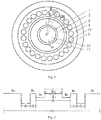
Fig. 1 is a schematic diagram of an end face structure of a single-mode optical fiber with ultra-low attenuation and a large effective area in the embodiment of the present invention; -
Fig. 2 is a schematic diagram of a waveguide structure of a single-mode optical fiber with ultra-low attenuation and a large effective area in the embodiment of the present invention. - In the figures: 1-core layer; 10-inner core layer; 11-transition core layer; 2-the first cladding layer; 3-the second cladding layer; 4-the third cladding layer; 40-micropore; 5-the fourth cladding layer.
- The present invention will be further described below in detail with reference to the drawings in combination with the embodiments.
- As shown in
Fig. 1 , the embodiment of the present invention provides a single-mode optical fiber with ultra-low attenuation and a large effective area. The single-mode optical fiber comprises acore layer 1, a first cladding layer 2, asecond cladding layer 3, athird cladding layer 4 and afourth cladding layer 5 successively arranged from inside to outside. The first cladding layer 2 is made from fluorine-doped quartz. Thesecond cladding layer 3, thethird cladding layer 4 and thefourth cladding layer 5 are all made from quartz. - As shown in
Fig. 1 , thethird cladding layer 4 is provided with at least one annular microporous layer successively arranged from inside to outside. The annular microporous layer comprises a plurality ofmicropores 40 which are evenly distributed, each of themicropores 40 in each annular microporous layer is equally spaced and the circle center of eachmicropore 40 in each annular microporous layer is concyclic and the circle is concentric with thecore layer 1. - The
core layer 1 is made from alkali metal-doped quartz, and the alkali metal is at least one of potassium and lithium existing in the form of oxides in the quartz. Thecore layer 1 comprises aninner core layer 10 and atransition core layer 11 successively arranged from inside to outside. - As shown in
Fig. 2 , the refractive indices of thetransition core layer 11 and thefourth cladding layer 5 are n11 and n5, respectively. The relative refractive index difference Δn11 between n11 and n5 satisfies
transition core layer 11, the value range of a is 1.05≤a≤1.3, and x is the distance from any point in thetransition core layer 11 to the edge of theinner core layer 10. The relative refractive index difference Δn11 of thetransition core layer 11 adopts a design concept combining logarithmic with parabola, which makes the waveguide change smoother and has a better viscosity matching effect. - In this embodiment, the calculation method of the relative refractive index difference Δ adopts the formula:

fourth cladding layer 5. For the present invention, when calculating the relative refractive index difference Δn11 between the refractive index n11 of thetransition core layer 11 and the refractive index n5 of thefourth cladding layer 5, nrefractive index in the formula is the refractive index n11 of thetransition core layer 11; when calculating the relative refractive index difference Δn2 between the refractive index n2 of the first cladding layer 2 and the refractive index n5 of thefourth cladding layer 5, nrefractive index in the formula is the refractive index n2 of the first cladding layer 2, the refractive index n10 of theinner core layer 10 and the refractive index n3 of thesecond cladding layer 3 are the same as the refractive index n5 of thefourth cladding layer 5. - In this embodiment, in order to satisfy total reflection and make the refractive index of the
core layer 1 higher than that of the first cladding layer 2, the first cladding layer 2 can be doped with fluorine. After being doped with fluorine, the viscosity of the first cladding layer 2 will decrease, making the viscosity of the core-cladding have a large difference, and due to the mismatch of viscosity, the expansion on heating and contraction on cooling at high and low temperatures are not matched during the manufacturing process, resulting in relatively large stresses between thecore layer 1 and the first cladding layer 2, then these stresses act on thecore layer 1, greatly increasing the loss of the optical passing through thecore layer 1. Therefore, in order to meet the ultra-low loss, thecore layer 1 is doped with alkali metal to reduce the viscosity of thecore layer 1, and at the same time, not to bring too much additional loss-absorbing material in the communication band, thereby achieving the viscosity matching of thecore layer 1 and the first cladding layer 2. - In the embodiment, the
third cladding layer 4 is further provided with an annular microporous layer. Starting from the normalized frequency of the optical fiber, the micropore duty cycle conditions of the optical fiber under small bending conditions are calculated and optimized, and the co-dopant doping is combined to reduce the viscosity to achieve the optimization of the core-cladding interface stress, thereby obtaining an ultra-low attenuation large effective area single-mode optical fiber with small bending radius. Due to the combination of normalized frequency and special small bending radius design, the single-mode optical fiber has good resistance to external stress. - The single-mode optical fiber provided by the present invention adopts a method of a core layer doped with alkali metal + a cladding layer doped with fluorine and combining with annular micropores. Compared with the method of a pure quartz core layer + a cladding layer doped with fluorine, the optical signal is better confined within the core diameter on the basis of solving the stress matching, thereby achieving a large mode field while reducing the dissipation of high-order modes, ensuring the transmission efficiency of the fundamental mode, not only meeting the characteristics of ultra-low attenuation and a large effective area and being able to achieve optical signal transmission with a larger mode field under ultra-low attenuation, but also having good bending performance, not only reducing the nonlinearity of large-capacity transmission, but also applying the ultra-low attenuation optical fiber to fields such as access networks and fiber-to-the-home that have higher requirements for the optical fiber bending performance, thereby effectively expanding the application prospect of the ultra-low attenuation optical fiber in large-capacity communication transmission technology, realizing the application of the ultra-low attenuation optical fiber in the entire optical fiber communication network, and truly realizing the optical fiber technology upgrade of the existing optical fiber communication network.
- When the working wavelength is 1550nm, the attenuation of the single-mode optical fiber reaches 0.150dB/km, the mode field diameter reaches 13.5µm, and the minimum bending radius reaches 10mm when the additional loss is less than 0.2dB.
- This embodiment also realizes the development of a full-band ultra-low attenuation optical fiber with a low cut-off wavelength, so that the cut-off wavelength of the optical fiber is less than 1290nm, and the attenuation of the optical fiber at 1310nm reaches 0.29dB/km, thereby better meeting the development needs of the ultra-large-capacity optical fiber communication transmission.
- In the above formula, the value of x is related to the thickness of the
transition core layer 11. Specifically, the value range of x is 0≤x≤d11, and 1.25µm≤d11≤2.50µm, wherein d11 is the thickness of thetransition core layer 11, as shown inFig. 1 . - As shown in
Fig. 2 , the diameter of thecore layer 1 is d1, and the value range is 8.5µm≤d1≤13µm; - the value range of the ratio of the outer diameter d2 of the first cladding layer 2 to d1 is 5≤d2/d1≤8;
- the value range of the ratio of the thickness d3 of the
second cladding layer 3 to d1 is 0.2≤d3/d1≤0.5; - the value range of the ratio of the thickness d4 of the
third cladding layer 4 to d1 is 1.0≤d4/d1≤3.0; at the same time, when d2/d1 takes the maximum value, d3/d1 and d4/d1 take the minimum value; and when d2/d1 takes the minimum value, d3/d1 and d4/d1 take the maximum value. - As shown in
Fig. 1 , the value range of the ratio of the diameter d40 of themicropore 40 to the thickness d4 of thethird cladding layer 4 is 0.25/m≤d40/d4≤0.4/m, wherein m is the total number of the annular microporous layers. - For example, when m=1, that is, when there is only one annular microporous layer, the value range of the ratio of the diameter d40 of the
micropore 40 to d4 is 0.25≤d40/d4≤0.4;
when m=2, that is, when there are two annular microporous layers, themicropores 40 in each annular microporous layer have the same size, and the value range of the ratio of the diameter d40 of themicropore 40 to d4 is 0.125≤d40/d4≤0.2; when m is other numbers, and so on. - In the
third cladding layer 4, one or more annular microporous layers are involved. For the distance between twoadjacent micropores 40 in the first annular microporous layer, the distance is determined by the included angle between the circle centers of the twomicropores 40 and the circle center of thecore layer 1 and the distance of the circles centers between themicropore 40 and thecore layer 1. - Specifically, as shown in
Fig. 1 : in each annular microporous layer, the diameter of themicropore 40 is d40, the distance between twoadjacent micropores 40 is h, the included angle formed by the lines respectively connecting the circle centers of the twoadjacent micropores 40 with the circle center of thecore layer 1 is α, and the distance of the circles centers between themicropore 40 and thecore layer 1 is L. Then h satisfies the following formula: h=2Lsin(α/2)-d40, and the distance between twoadjacent micropores 40 in different annular microporous layers is equal, that is, after the distance h between twoadjacent micropores 40 in the first layer of annular microporous layer is determined, the distance h between twoadjacent micropores 40 in each annular microporous layer of the second layer, third layer, etc. is equal to the distance h between twoadjacent micropores 40 in the first layer of annular microporous layer. - The value range of the included angle α is 15°≤α≤30°.
- In addition, when the total number of annular microporous layers m≥2, the distance between two adjacent annular microporous layers is equal to the distance h between two
adjacent micropores 40. - Because the single-mode optical fiber provided by the present invention has good resistance to external stress, the diameter of the
fourth cladding layer 5 is usually 125µm, and when thefourth cladding layer 5 is used in occasions where frequent butting is required, the diameter thereof can be controlled at 124µm, then a coating material (tight coating) that tightly adheres to quartz is coated, the diameter of the optical fiber is coated to 125µm, then two coats of polyacrylic resin are performed to form a coating layer, which can still maintain good attenuation characteristics, and the diameter of the coated single-mode optical fiber is 235µm∼260µm; in the subsequent use, only the polyacrylic resin coating layer needs to be stripped, since the quartz optical fiber still has a coating material to protect it from outside air, moisture and dust, it is not necessary to connect the two optical fibers by thermal fusion, but only need to fix the connector through the cold connection of the connector to ensure the good use of the optical fiber. - The present invention will be further described below in detail in combination with embodiments and drawings.
- When the diameter of the
fourth cladding layer 5 is 125µm, 8 types of optical fibers are implemented. The specific parameters are shown in Table 1 below.Table 1 Embodiments with Diameter of Fourth Cladding Layer of 125µm Optical Fiber 1Optical Fiber 2 Optical Fiber 3Optical Fiber 4Optical Fiber 5Optical Fiber 6 Optical Fiber 7 Optical Fiber 8 Diameter d1 of Core Layer 1 (µm) 8.5 8.5 8.5 10.0 11.0 10.5 13.0 13.0 Thickness d11 of Transition Core Layer 11 (µm) 2.5 1.6 1.25 1.25 1.5 2.5 2.5 1.25 Transition Coefficient a 1.05 1.16 1.3 1.3 1.2 1.05 1.05 1.3 d2/ d 15 7 8 5 6 8 5.2 6 d3/d1 0.5 0.3 0.2 0.5 0.3 0.2 0.4 0.3 d4/ d 13 2 1 3 2 1 1.5 1.2 α 15° 20° 30° 20° 15° 30° 15° 30° Number of Annular Microporous Layers m 1 2 3 1 2 3 1 2 Diameter of Micropore 40 d40/d4 25% 30% 40% 40% 25% 30% 40% 25% Diameter of Coating Layer (µm) 235 245 260 260 235 250 235 260 - The optical fiber thus obtained has the attenuation of 0.150dB/km at 1550nm, the mode field diameter of 13.5µm, and the minimum bending radius of 10mm when the additional loss is less than 0.2dB at 1550nm; wherein when the core diameter of the optical fiber is 10.0µm and below, the cut-off wavelength of the optical fiber is less than 1290nm, and the attenuation of the optical fiber at 1310nm reaches 0.29dB/km.
- Combining the normalized frequency and special small bending radius design, the optical fiber can have good resistance to external stress. In the occasions where frequent butting is required, the diameter of the quartz cladding layer of the optical fiber can be controlled at 124µm, then a coating material that tightly adheres to the quartz is coated, the diameter of the optical fiber is coated to 125µm, then two coats of polyacrylic resin are performed, which can still maintain good attenuation characteristics; in the subsequent use, only the polyacrylic resin coating layer needs to be stripped, since the quartz optical fiber still has a coating material to protect it from outside air, moisture and dust, it is not necessary to connect the two optical fibers by thermal fusion, but only need to fix the connector through the cold connection of the connector to ensure the good use of the optical fiber.
- When the diameter of the
fourth cladding layer 5 is 124µm, three types of optical fibers are implemented. The specific parameters are shown in Table 2 below.Table 2 Embodiments with Diameter of Fourth Cladding Layer of 124µm Optical Fiber 9 Optical Fiber 10Optical Fiber 11Diameter d1 of Core Layer 1 (µm) 8.5 9 10 Thickness d11 of Transition Core Layer 11 (µm) 1.25 1.7 2.5 Transition Coefficient a 1.3 1.15 1.05 d2/d1 8 7 5 d3/d1 0.2 0.3 0.5 d4/ d 11 2 3 α 15° 20° 30° Number of Annular Micropore Layers m 4 3 3 Diameter of Micropore 40 d40/d4 25% 30% 40% Diameter after Tight Coating (µm) 125.1 125.2 124.9 Diameter of Coating Layer (µm) 245.2 240.3 246.5 - The optical fiber thus obtained has the cut-off wavelength of less than 1290nm, the attenuation of 0.29dB/km at 1310nm, 0.150dB/km at 1550nm, and the minimum bend radius of 10mm when the additional loss of less than 0.2dB at 1550nm; under the condition of ensuring the attenuation of the optical fiber, the present invention can realize an optical fiber butting that can be adapted to rapid cold butting, thereby being suitable for rapid installation and use in special occasions.
- The present invention is not limited to the above-mentioned embodiments. One skilled in the art may make a number of improvements and modifications without departing from the principle of the present invention, and these improvements and modifications are also considered to be within the protection scope of the present invention. The contents that are not described in detail in the description belong to the prior art well known by one skilled in the art.
Claims (13)
- A single-mode optical fiber with ultra-low attenuation and a large effective area, comprising: a core layer (1), a first cladding layer (2), a second cladding layer (3), a third cladding layer (4) and a fourth cladding layer (5) successively arranged from inside to outside;the first cladding layer (2) is made from fluorine-doped quartz;the second cladding layer (3), the third cladding layer (4) and the fourth cladding layer (5) are all made from quartz;the third cladding layer (4) is provided with at least one annular microporous layer successively arranged from inside to outside, the annular microporous layer comprises a plurality of micropores (40) which are evenly distributed, the circle center of each micropore (40) in each annular microporous layer is concyclic and the circle is concentric with the core layer (1);the core layer (1) is made from alkali metal-doped quartz, and the core layer (1) comprises an inner core layer (10) and a transition core layer (11) successively arranged from inside to outside;the refractive indices of the transition core layer (11) and the fourth cladding layer (5) are n11 and n5, respectively, and the relative refractive index difference Δn11 between n11 and n5 satisfies

- The single-mode optical fiber with ultra-low attenuation and a large effective area according to claim 1, wherein the value range of a is 1.05≤a≤1.3.
- The single-mode optical fiber with ultra-low attenuation and a large effective area according to claim 1, wherein the value range of x is 0≤x≤d11, and 1.25µm≤d11≤2.50µm, wherein d11 is the thickness of the transition core layer (11).
- The single-mode optical fiber with ultra-low attenuation and a large effective area according to claim 1, whereinthe diameter of the core layer (1) is d1;the value range of the ratio of the outer diameter d2 of the first cladding layer (2) to d1 is 5≤d2/d1≤8;the value range of the ratio of the thickness d3 of the second cladding layer (3) to d1 is 0.2≤d3/d1≤0.5;the value range of the ratio of the thickness d4 of the third cladding layer (4) to d1 is 1.0≤d4/d1≤3.0; at the same time,when d2/d1 takes the maximum value, d3/d1 and d4/d1 take the minimum value; and when d2/d1 takes the minimum value, d3/d1 and d4/d1 take the maximum value.
- The single-mode optical fiber with ultra-low attenuation and a large effective area according to claim 4, wherein value range of the diameter d1 of the core layer (1) is 8.5 µm≤d1≤13 µm.
- The single-mode optical fiber with ultra-low attenuation and a large effective area according to claim 1, wherein the value range of the ratio of the diameter d40 of the micropore (40) to the thickness d4 of the third cladding layer (4) is 0.25/m≤d40/d4≤0.4/m, wherein m is the total number of the annular microporous layers.
- The single-mode optical fiber with ultra-low attenuation and a large effective area according to claim 1, wherein in each annular microporous layer, the diameter of the micropore (40) is d40, the distance between two adjacent micropores (40) is h, an included angle formed by the lines respectively connecting the circle centers of the two adjacent micropores (40) with the circle center of the core layer (1) is α, the distance of the circles centers between the micropore (40) and the core layer (1) is L, then h satisfies the following formula: h=2Lsin(α/2)-d40, and the distance h between two adjacent micropores (40) in different annular microporous layers is equal.
- The single-mode optical fiber with ultra-low attenuation and a large effective area according to claim 7, wherein the value range of the included angle α is 15°≤α≤30°.
- The single-mode optical fiber with ultra-low attenuation and a large effective area according to claim 1, wherein the inner core layer (10), the second cladding layer (3) and the fourth cladding layer (5) have the same refractive index.
- The single-mode optical fiber with ultra-low attenuation and a large effective area according to claim 1, wherein the alkali metal is at least one of potassium and lithium.
- The single-mode optical fiber with ultra-low attenuation and a large effective area according to claim 1, wherein the diameter d5 of the fourth cladding layer (5) is 125 µm or 124 µm.
- The single-mode optical fiber with ultra-low attenuation and a large effective area according to claim 1, wherein the diameter of a coated single-mode optical fiber is 235µm~260µm.
- The single-mode optical fiber with ultra-low attenuation and a large effective area according to claim 1, wherein when a working wavelength is 1550nm, an attenuation of the single-mode optical fiber reaches 0.150dB/km, a mode field diameter reaches 13.5µm, and a minimum bending radius reaches 10mm when an additional loss is less than 0.2dB.
Applications Claiming Priority (2)
| Application Number | Priority Date | Filing Date | Title |
|---|---|---|---|
| CN201910507964.8A CN110221382B (en) | 2019-06-12 | 2019-06-12 | A single-mode fiber with ultra-low attenuation and large effective area |
| PCT/CN2019/124965 WO2020248552A1 (en) | 2019-06-12 | 2019-12-13 | Ultra-low attenuation large effective area single-mode optical fibre |
Publications (4)
| Publication Number | Publication Date |
|---|---|
| EP3907538A1 true EP3907538A1 (en) | 2021-11-10 |
| EP3907538A4 EP3907538A4 (en) | 2022-10-05 |
| EP3907538B1 EP3907538B1 (en) | 2024-10-23 |
| EP3907538C0 EP3907538C0 (en) | 2024-10-23 |
Family
ID=67816804
Family Applications (1)
| Application Number | Title | Priority Date | Filing Date |
|---|---|---|---|
| EP19932669.5A Active EP3907538B1 (en) | 2019-06-12 | 2019-12-13 | Ultra-low attenuation large effective area single-mode optical fibre |
Country Status (5)
| Country | Link |
|---|---|
| EP (1) | EP3907538B1 (en) |
| CN (1) | CN110221382B (en) |
| EC (1) | ECSP21039141A (en) |
| HU (1) | HUE069058T2 (en) |
| WO (1) | WO2020248552A1 (en) |
Families Citing this family (5)
| Publication number | Priority date | Publication date | Assignee | Title |
|---|---|---|---|---|
| CN110221382B (en) * | 2019-06-12 | 2020-07-07 | 烽火通信科技股份有限公司 | A single-mode fiber with ultra-low attenuation and large effective area |
| CN112649916B (en) * | 2020-12-25 | 2022-06-28 | 长飞光纤光缆股份有限公司 | Dispersion compensation optical fiber and module for miniaturized device |
| CN112666650B (en) * | 2020-12-30 | 2022-07-22 | 电子科技大学 | Large cross section single mode optical fiber |
| CN112897872A (en) * | 2021-01-28 | 2021-06-04 | 通鼎互联信息股份有限公司 | Manufacturing method of large mode field bending loss insensitive single mode fiber for access network |
| CN117945640A (en) * | 2024-02-02 | 2024-04-30 | 远东通讯有限公司 | Bending insensitive optical fiber preform and preparation method thereof |
Family Cites Families (22)
| Publication number | Priority date | Publication date | Assignee | Title |
|---|---|---|---|---|
| KR900003449B1 (en) * | 1986-06-11 | 1990-05-19 | 스미도모덴기고오교오 가부시기가이샤 | Dispersion-shift fiber and its production |
| JP2003029062A (en) * | 2001-07-13 | 2003-01-29 | Sumitomo Electric Ind Ltd | Optical fiber with built-in grating and optical fiber for forming grating |
| US6707976B1 (en) * | 2002-09-04 | 2004-03-16 | Fitel Usa Corporation | Inverse dispersion compensating fiber |
| JP2005208268A (en) * | 2004-01-22 | 2005-08-04 | Nippon Telegr & Teleph Corp <Ntt> | Optical fiber |
| CN101506703A (en) * | 2006-08-24 | 2009-08-12 | 康宁股份有限公司 | Optical fiber containing alkali metal oxide |
| US7283714B1 (en) * | 2006-12-15 | 2007-10-16 | Ipg Photonics Corporation | Large mode area fiber for low-loss transmission and amplification of single mode lasers |
| CN102200610B (en) * | 2011-05-27 | 2012-10-17 | 成都富通光通信技术有限公司 | Dispersion-optimized single-mode fiber for ultra-high-speed long-haul dense wavelength division multiplexing |
| US8666214B2 (en) * | 2011-11-30 | 2014-03-04 | Corning Incorporated | Low bend loss optical fiber |
| JP5735468B2 (en) * | 2012-08-31 | 2015-06-17 | 株式会社フジクラ | Optical fiber, method for manufacturing the same, and method for manufacturing optical fiber preform |
| CN104360435A (en) * | 2014-08-25 | 2015-02-18 | 长飞光纤光缆股份有限公司 | Bend-insensitive multimode fiber |
| JP2017535804A (en) * | 2014-09-29 | 2017-11-30 | コーニング インコーポレイテッド | Quasi-single mode optical fiber with large effective area |
| US9841555B2 (en) * | 2014-09-29 | 2017-12-12 | Corning Incorporated | Optical transmission systems and methods using a QSM large-effective-area optical fiber |
| CN104536085B (en) * | 2015-01-07 | 2017-06-20 | 烽火通信科技股份有限公司 | A kind of thin footpath polarization maintaining optical fibre |
| CN104698535A (en) * | 2015-03-31 | 2015-06-10 | 长飞光纤光缆股份有限公司 | Bent insensitive multi-mode optical fiber |
| CN104898200B (en) * | 2015-06-25 | 2018-03-16 | 长飞光纤光缆股份有限公司 | A kind of ultralow decay single-mode fiber for adulterating optimization |
| JP6690296B2 (en) * | 2016-02-26 | 2020-04-28 | 住友電気工業株式会社 | Optical fiber |
| CN105891947A (en) * | 2016-05-31 | 2016-08-24 | 夏烬楚 | Multi-air cladding anti-bending optical fiber and manufacturing method thereof |
| CN106291808B (en) * | 2016-09-18 | 2019-05-24 | 长飞光纤光缆股份有限公司 | A kind of ultralow attenuation large effective area single mode optical fiber |
| CN107422414A (en) * | 2017-05-04 | 2017-12-01 | 长飞光纤光缆股份有限公司 | A kind of low decay bend-insensitive single-mode optical fiber |
| CN107721149A (en) * | 2017-11-01 | 2018-02-23 | 江苏亨通光导新材料有限公司 | Axial vapor deposition method prepares ultra-low-loss fiber prefabricated rods and optical fiber |
| CN109683232A (en) * | 2019-02-22 | 2019-04-26 | 长飞光纤光缆股份有限公司 | Single mode optical fiber with ultralow attenuation large effective area |
| CN110221382B (en) * | 2019-06-12 | 2020-07-07 | 烽火通信科技股份有限公司 | A single-mode fiber with ultra-low attenuation and large effective area |
-
2019
- 2019-06-12 CN CN201910507964.8A patent/CN110221382B/en active Active
- 2019-12-13 WO PCT/CN2019/124965 patent/WO2020248552A1/en not_active Ceased
- 2019-12-13 EP EP19932669.5A patent/EP3907538B1/en active Active
- 2019-12-13 HU HUE19932669A patent/HUE069058T2/en unknown
-
2021
- 2021-05-31 EC ECSENADI202139141A patent/ECSP21039141A/en unknown
Also Published As
| Publication number | Publication date |
|---|---|
| WO2020248552A1 (en) | 2020-12-17 |
| EP3907538B1 (en) | 2024-10-23 |
| RU2769089C1 (en) | 2022-03-28 |
| CN110221382B (en) | 2020-07-07 |
| CN110221382A (en) | 2019-09-10 |
| HUE069058T2 (en) | 2025-02-28 |
| ECSP21039141A (en) | 2021-08-31 |
| EP3907538C0 (en) | 2024-10-23 |
| BR112021008221A2 (en) | 2022-01-04 |
| EP3907538A4 (en) | 2022-10-05 |
Similar Documents
| Publication | Publication Date | Title |
|---|---|---|
| EP3907538B1 (en) | Ultra-low attenuation large effective area single-mode optical fibre | |
| EP3715923B1 (en) | Single-mode optical fiber with ultralow loss and large effective area and manufacturing method therefor | |
| CN113272691B (en) | Multicore optical fibers and design methods | |
| EP3141938B1 (en) | Low-loss few-mode optical fiber | |
| EP3141937B1 (en) | Small-diameter polarization maintaining optical fibre | |
| CN105425335B (en) | A kind of communication bending resistance multi-core optical fiber | |
| CN110244404B (en) | Low-attenuation ring-shaped fiber core optical fiber | |
| EP3290973B1 (en) | Ultralow-attenuation bend-insensitive single-mode optical fibre | |
| JPWO2014087974A1 (en) | Optical waveguide and optical fiber transmission system | |
| EP3637160A1 (en) | Small core-diameter graded-index optical fiber | |
| CN105511015B (en) | A kind of less fundamental mode optical fibre | |
| CN107678087A (en) | A kind of low attenuation large effective area single-mode fiber | |
| EP3290972B1 (en) | Ultralow attenuation single mode optical fiber | |
| CN106842419A (en) | A kind of broadband bend-insensitive multimode fibre | |
| CN106707407A (en) | Wideband semi-step type multimode optical fiber | |
| US12580359B2 (en) | Amplifying optical fibers | |
| CN117666012A (en) | High-broadband low-loss bending-resistant multimode optical fiber | |
| EP4535049A1 (en) | Small-diameter single-mode optical fiber | |
| CN108363139A (en) | A kind of two mode fibers of ultralow decaying of step change type | |
| CN205507132U (en) | Few mode fiber | |
| CN108415120A (en) | A kind of two mode fibers of ultralow decaying of gradation type | |
| RU2769089C9 (en) | Single-mode optical fibre with ultra-low attenuation and large effective area | |
| CN110346865B (en) | Polarization maintaining optical fiber used in multiple bands | |
| CN109358391B (en) | A single-mode coupled fiber with low macrobending loss | |
| BR112021008221B1 (en) | SINGLE-MODE OPTIC FIBER WITH ULTRA-LOW ATTENUATION AND A LARGE EFFECTIVE AREA |
Legal Events
| Date | Code | Title | Description |
|---|---|---|---|
| STAA | Information on the status of an ep patent application or granted ep patent |
Free format text: STATUS: THE INTERNATIONAL PUBLICATION HAS BEEN MADE |
|
| PUAI | Public reference made under article 153(3) epc to a published international application that has entered the european phase |
Free format text: ORIGINAL CODE: 0009012 |
|
| STAA | Information on the status of an ep patent application or granted ep patent |
Free format text: STATUS: REQUEST FOR EXAMINATION WAS MADE |
|
| 17P | Request for examination filed |
Effective date: 20210519 |
|
| AK | Designated contracting states |
Kind code of ref document: A1 Designated state(s): AL AT BE BG CH CY CZ DE DK EE ES FI FR GB GR HR HU IE IS IT LI LT LU LV MC MK MT NL NO PL PT RO RS SE SI SK SM TR |
|
| DAV | Request for validation of the european patent (deleted) | ||
| DAX | Request for extension of the european patent (deleted) | ||
| A4 | Supplementary search report drawn up and despatched |
Effective date: 20220907 |
|
| RIC1 | Information provided on ipc code assigned before grant |
Ipc: G02B 6/028 20060101ALI20220901BHEP Ipc: G02B 6/02 20060101ALI20220901BHEP Ipc: G02B 6/036 20060101AFI20220901BHEP |
|
| GRAP | Despatch of communication of intention to grant a patent |
Free format text: ORIGINAL CODE: EPIDOSNIGR1 |
|
| GRAP | Despatch of communication of intention to grant a patent |
Free format text: ORIGINAL CODE: EPIDOSNIGR1 |
|
| STAA | Information on the status of an ep patent application or granted ep patent |
Free format text: STATUS: GRANT OF PATENT IS INTENDED |
|
| RIC1 | Information provided on ipc code assigned before grant |
Ipc: G02B 6/028 20060101ALI20240523BHEP Ipc: G02B 6/02 20060101ALI20240523BHEP Ipc: G02B 6/036 20060101AFI20240523BHEP |
|
| INTG | Intention to grant announced |
Effective date: 20240614 |
|
| GRAS | Grant fee paid |
Free format text: ORIGINAL CODE: EPIDOSNIGR3 |
|
| GRAA | (expected) grant |
Free format text: ORIGINAL CODE: 0009210 |
|
| STAA | Information on the status of an ep patent application or granted ep patent |
Free format text: STATUS: THE PATENT HAS BEEN GRANTED |
|
| AK | Designated contracting states |
Kind code of ref document: B1 Designated state(s): AL AT BE BG CH CY CZ DE DK EE ES FI FR GB GR HR HU IE IS IT LI LT LU LV MC MK MT NL NO PL PT RO RS SE SI SK SM TR |
|
| REG | Reference to a national code |
Ref country code: GB Ref legal event code: FG4D |
|
| REG | Reference to a national code |
Ref country code: CH Ref legal event code: EP |
|
| REG | Reference to a national code |
Ref country code: DE Ref legal event code: R096 Ref document number: 602019060980 Country of ref document: DE |
|
| REG | Reference to a national code |
Ref country code: IE Ref legal event code: FG4D |
|
| U01 | Request for unitary effect filed |
Effective date: 20241118 |
|
| U07 | Unitary effect registered |
Designated state(s): AT BE BG DE DK EE FI FR IT LT LU LV MT NL PT RO SE SI Effective date: 20241125 |
|
| U20 | Renewal fee for the european patent with unitary effect paid |
Year of fee payment: 6 Effective date: 20241127 |
|
| REG | Reference to a national code |
Ref country code: HU Ref legal event code: AG4A Ref document number: E069058 Country of ref document: HU |
|
| PG25 | Lapsed in a contracting state [announced via postgrant information from national office to epo] |
Ref country code: HR Free format text: LAPSE BECAUSE OF FAILURE TO SUBMIT A TRANSLATION OF THE DESCRIPTION OR TO PAY THE FEE WITHIN THE PRESCRIBED TIME-LIMIT Effective date: 20241023 Ref country code: IS Free format text: LAPSE BECAUSE OF FAILURE TO SUBMIT A TRANSLATION OF THE DESCRIPTION OR TO PAY THE FEE WITHIN THE PRESCRIBED TIME-LIMIT Effective date: 20250223 |
|
| PG25 | Lapsed in a contracting state [announced via postgrant information from national office to epo] |
Ref country code: ES Free format text: LAPSE BECAUSE OF FAILURE TO SUBMIT A TRANSLATION OF THE DESCRIPTION OR TO PAY THE FEE WITHIN THE PRESCRIBED TIME-LIMIT Effective date: 20241023 |
|
| PG25 | Lapsed in a contracting state [announced via postgrant information from national office to epo] |
Ref country code: NO Free format text: LAPSE BECAUSE OF FAILURE TO SUBMIT A TRANSLATION OF THE DESCRIPTION OR TO PAY THE FEE WITHIN THE PRESCRIBED TIME-LIMIT Effective date: 20250123 |
|
| PG25 | Lapsed in a contracting state [announced via postgrant information from national office to epo] |
Ref country code: GR Free format text: LAPSE BECAUSE OF FAILURE TO SUBMIT A TRANSLATION OF THE DESCRIPTION OR TO PAY THE FEE WITHIN THE PRESCRIBED TIME-LIMIT Effective date: 20250124 |
|
| PG25 | Lapsed in a contracting state [announced via postgrant information from national office to epo] |
Ref country code: PL Free format text: LAPSE BECAUSE OF FAILURE TO SUBMIT A TRANSLATION OF THE DESCRIPTION OR TO PAY THE FEE WITHIN THE PRESCRIBED TIME-LIMIT Effective date: 20241023 |
|
| PG25 | Lapsed in a contracting state [announced via postgrant information from national office to epo] |
Ref country code: RS Free format text: LAPSE BECAUSE OF FAILURE TO SUBMIT A TRANSLATION OF THE DESCRIPTION OR TO PAY THE FEE WITHIN THE PRESCRIBED TIME-LIMIT Effective date: 20250123 |
|
| PG25 | Lapsed in a contracting state [announced via postgrant information from national office to epo] |
Ref country code: SM Free format text: LAPSE BECAUSE OF FAILURE TO SUBMIT A TRANSLATION OF THE DESCRIPTION OR TO PAY THE FEE WITHIN THE PRESCRIBED TIME-LIMIT Effective date: 20241023 |
|
| PG25 | Lapsed in a contracting state [announced via postgrant information from national office to epo] |
Ref country code: MC Free format text: LAPSE BECAUSE OF FAILURE TO SUBMIT A TRANSLATION OF THE DESCRIPTION OR TO PAY THE FEE WITHIN THE PRESCRIBED TIME-LIMIT Effective date: 20241023 |
|
| PG25 | Lapsed in a contracting state [announced via postgrant information from national office to epo] |
Ref country code: SK Free format text: LAPSE BECAUSE OF FAILURE TO SUBMIT A TRANSLATION OF THE DESCRIPTION OR TO PAY THE FEE WITHIN THE PRESCRIBED TIME-LIMIT Effective date: 20241023 |
|
| PG25 | Lapsed in a contracting state [announced via postgrant information from national office to epo] |
Ref country code: CZ Free format text: LAPSE BECAUSE OF FAILURE TO SUBMIT A TRANSLATION OF THE DESCRIPTION OR TO PAY THE FEE WITHIN THE PRESCRIBED TIME-LIMIT Effective date: 20241023 |
|
| REG | Reference to a national code |
Ref country code: CH Ref legal event code: PL |
|
| PLBE | No opposition filed within time limit |
Free format text: ORIGINAL CODE: 0009261 |
|
| STAA | Information on the status of an ep patent application or granted ep patent |
Free format text: STATUS: NO OPPOSITION FILED WITHIN TIME LIMIT |
|
| GBPC | Gb: european patent ceased through non-payment of renewal fee |
Effective date: 20250123 |
|
| 26N | No opposition filed |
Effective date: 20250724 |
|
| PG25 | Lapsed in a contracting state [announced via postgrant information from national office to epo] |
Ref country code: GB Free format text: LAPSE BECAUSE OF NON-PAYMENT OF DUE FEES Effective date: 20250123 |
|
| PG25 | Lapsed in a contracting state [announced via postgrant information from national office to epo] |
Ref country code: CH Free format text: LAPSE BECAUSE OF NON-PAYMENT OF DUE FEES Effective date: 20241231 |
|
| PG25 | Lapsed in a contracting state [announced via postgrant information from national office to epo] |
Ref country code: IE Free format text: LAPSE BECAUSE OF NON-PAYMENT OF DUE FEES Effective date: 20241213 |
|
| U20 | Renewal fee for the european patent with unitary effect paid |
Year of fee payment: 7 Effective date: 20251127 |
|
| PGFP | Annual fee paid to national office [announced via postgrant information from national office to epo] |
Ref country code: HU Payment date: 20251124 Year of fee payment: 7 |
|
| PG25 | Lapsed in a contracting state [announced via postgrant information from national office to epo] |
Ref country code: CY Free format text: LAPSE BECAUSE OF FAILURE TO SUBMIT A TRANSLATION OF THE DESCRIPTION OR TO PAY THE FEE WITHIN THE PRESCRIBED TIME-LIMIT Effective date: 20241023 |