EP3907434A1 - Air inlet and exhaust assembly, and integrated air conditioner - Google Patents
Air inlet and exhaust assembly, and integrated air conditioner Download PDFInfo
- Publication number
- EP3907434A1 EP3907434A1 EP20914758.6A EP20914758A EP3907434A1 EP 3907434 A1 EP3907434 A1 EP 3907434A1 EP 20914758 A EP20914758 A EP 20914758A EP 3907434 A1 EP3907434 A1 EP 3907434A1
- Authority
- EP
- European Patent Office
- Prior art keywords
- air
- pipe
- exhaust
- air intake
- air exhaust
- Prior art date
- Legal status (The legal status is an assumption and is not a legal conclusion. Google has not performed a legal analysis and makes no representation as to the accuracy of the status listed.)
- Granted
Links
Images



Classifications
-
- F—MECHANICAL ENGINEERING; LIGHTING; HEATING; WEAPONS; BLASTING
- F24—HEATING; RANGES; VENTILATING
- F24F—AIR-CONDITIONING; AIR-HUMIDIFICATION; VENTILATION; USE OF AIR CURRENTS FOR SCREENING
- F24F13/00—Details common to, or for air-conditioning, air-humidification, ventilation or use of air currents for screening
- F24F13/02—Ducting arrangements
-
- F—MECHANICAL ENGINEERING; LIGHTING; HEATING; WEAPONS; BLASTING
- F24—HEATING; RANGES; VENTILATING
- F24F—AIR-CONDITIONING; AIR-HUMIDIFICATION; VENTILATION; USE OF AIR CURRENTS FOR SCREENING
- F24F13/00—Details common to, or for air-conditioning, air-humidification, ventilation or use of air currents for screening
- F24F13/02—Ducting arrangements
- F24F13/0281—Multilayer duct
-
- F—MECHANICAL ENGINEERING; LIGHTING; HEATING; WEAPONS; BLASTING
- F24—HEATING; RANGES; VENTILATING
- F24F—AIR-CONDITIONING; AIR-HUMIDIFICATION; VENTILATION; USE OF AIR CURRENTS FOR SCREENING
- F24F1/00—Room units for air-conditioning, e.g. separate or self-contained units or units receiving primary air from a central station
- F24F1/02—Self-contained room units for air-conditioning, i.e. with all apparatus for treatment installed in a common casing
- F24F1/028—Self-contained room units for air-conditioning, i.e. with all apparatus for treatment installed in a common casing characterised by air supply means, e.g. fan casings, internal dampers or ducts
-
- F—MECHANICAL ENGINEERING; LIGHTING; HEATING; WEAPONS; BLASTING
- F24—HEATING; RANGES; VENTILATING
- F24F—AIR-CONDITIONING; AIR-HUMIDIFICATION; VENTILATION; USE OF AIR CURRENTS FOR SCREENING
- F24F13/00—Details common to, or for air-conditioning, air-humidification, ventilation or use of air currents for screening
- F24F13/30—Arrangement or mounting of heat-exchangers
-
- F—MECHANICAL ENGINEERING; LIGHTING; HEATING; WEAPONS; BLASTING
- F24—HEATING; RANGES; VENTILATING
- F24F—AIR-CONDITIONING; AIR-HUMIDIFICATION; VENTILATION; USE OF AIR CURRENTS FOR SCREENING
- F24F13/00—Details common to, or for air-conditioning, air-humidification, ventilation or use of air currents for screening
- F24F13/02—Ducting arrangements
- F24F13/06—Outlets for directing or distributing air into rooms or spaces, e.g. ceiling air diffuser
- F24F2013/0616—Outlets that have intake openings
-
- Y—GENERAL TAGGING OF NEW TECHNOLOGICAL DEVELOPMENTS; GENERAL TAGGING OF CROSS-SECTIONAL TECHNOLOGIES SPANNING OVER SEVERAL SECTIONS OF THE IPC; TECHNICAL SUBJECTS COVERED BY FORMER USPC CROSS-REFERENCE ART COLLECTIONS [XRACs] AND DIGESTS
- Y02—TECHNOLOGIES OR APPLICATIONS FOR MITIGATION OR ADAPTATION AGAINST CLIMATE CHANGE
- Y02B—CLIMATE CHANGE MITIGATION TECHNOLOGIES RELATED TO BUILDINGS, e.g. HOUSING, HOUSE APPLIANCES OR RELATED END-USER APPLICATIONS
- Y02B30/00—Energy efficient heating, ventilation or air conditioning [HVAC]
- Y02B30/56—Heat recovery units
Definitions
- the present disclosure relates to the field of air-conditioning technologies, and more particularly, to an air intake and exhaust assembly and a packaged air conditioner.
- the dual air pipes include two independent air pipes, which are respectively used for connecting to an outdoor heat exchanger to realize air intake and connecting to an air exhaust volute to realize air exhaust, such that the packaged air conditioner can exchange heat with an outdoor environment.
- a dual-air-pipe structure is relatively complicated for a user to install, which results in poor user experience and has an unsightly appearance.
- the present disclosure aims at solving at least one of the technical problems in the related art. Therefore, the present disclosure provides an air intake and exhaust assembly, which is simple and convenient to install, aesthetically favorable in appearance, and improves user experience.
- the present disclosure further provides a packaged air conditioner, including the air intake and exhaust assembly above.
- an air intake and exhaust assembly applied to a packaged air conditioner including: an air exhaust pipe, an air exhaust channel is provided in the air exhaust pipe; a connecting pipe, where one end of the connecting pipe is connected to a lower end of the air exhaust pipe and the other end of the connecting pipe is connected to an air exhaust volute of the packaged air conditioner, such that the air exhaust channel is communicated with an air outlet of the air exhaust volute; and an air intake pipe, where the air intake pipe is arranged around the air exhaust pipe, an air intake channel is provided between an inner wall of the air intake pipe and an outer wall of the air exhaust pipe, and the air intake channel is communicated with an air inlet of the packaged air conditioner.
- the air intake and exhaust assembly according to the embodiments of the present disclosure at least has the following beneficial effects.
- a dual-air-pipe structure is formed by arranging an air exhaust pipe and an air intake pipe arranged around the air exhaust pipe in the air intake and exhaust assembly, which is simple and aesthetically favorable in structure, convenient for users to install and adjust the air intake and exhaust assembly, and improves user experience;
- an air intake channel is provided between the air intake pipe and the air exhaust pipe, such that the air intake channel is communicated with an air inlet of a packaged air conditioner to transfer outdoor air to an outdoor heat exchanger;
- the air exhaust channel is provided in the air exhaust pipe and connected to an air exhaust volute through a connecting pipe, such that an air outlet of the air exhaust volute is communicated with the air exhaust channel to discharge the air after heat exchange outdoors, thereby forming a sealed heat exchange duct and improving the heat exchange effect between the packaged air conditioner and the outdoor environment;
- the connecting pipe makes connection between the air exhaust pipe and the air exhaust volute more reliable, improves a sealing performance of the air exhaust channel, avoids air crossing between the air intake channel and the air exhaust channel, and improves the energy efficiency of the
- one end of the connecting pipe facing the air exhaust pipe is provided with a first installation port, and the lower end of the air exhaust pipe is provided with a first joint matching the first installation port.
- the first installation port is provided with a plurality of first buckles at intervals along a circumferential direction, and the plurality of first buckles are clamped with the first joint.
- the air inlet is provided with a second installation port, and one end of the air intake pipe facing the air inlet is provided with a second joint matching the second installation port.
- the second installation port is provided with a plurality of second buckles at intervals along a circumferential direction, and the plurality of second buckles are clamped with the second joint.
- the air intake and exhaust assembly further includes a sealing plate, where the sealing plate is provided with an air intake hole, and the air intake hole is connected to one end of the air intake pipe away from the air inlet.
- the sealing plate further includes a fixing ring, the fixing ring is arranged in the air intake hole and defines an air exhaust hole, the air exhaust hole is connected to one end of the air exhaust pipe away from the air outlet, and a connecting rib is arranged between the fixing ring and the sealing plate.
- a plurality of connecting ribs are provided, and the plurality of connecting ribs are arranged at intervals along a circumferential direction of the fixing ring.
- each of the air exhaust pipe, the connecting pipe and the air intake pipe is cylindrical.
- a packaged air conditioner including the air intake and exhaust assembly according to above embodiments.
- the packaged air conditioner according to the embodiments of the present disclosure at least has the following beneficial effects.
- a dual-air-pipe structure is formed by arranging an air exhaust pipe and an air intake pipe arranged around the air exhaust pipe in the air intake and exhaust assembly, which is simple and aesthetically favorable in structure, convenient for users to install and adjust the air intake and exhaust assembly, and improves user experience;
- an air intake channel is provided between the air intake pipe and the air exhaust pipe, such that the air intake channel is communicated with an air inlet of a packaged air conditioner to transfer outdoor air to an outdoor heat exchanger;
- the air exhaust channel is provided in the air exhaust pipe and connected to an air exhaust volute through a connecting pipe, such that an air outlet of the air exhaust volute is communicated with the air exhaust channel to discharge the air after heat exchange outdoors, thereby forming a sealed heat exchange duct and improving the heat exchange effect between the packaged air conditioner and the outdoor environment;
- the connecting pipe makes connection between the air exhaust pipe and the air exhaust volute more reliable, improves a sealing performance of the air exhaust channel, avoids air crossing between the air intake channel and the air exhaust channel, and improves the energy efficiency of the
- any orientation/position related description such as the orientational or positional relationship, such as, up, down, left, right, front, rear, and the like is based on the orientational or positional relationship shown in the accompanying drawings, is only for the purpose of facilitating the description of the present disclosure and simplifying the description, and does not indicate or imply that the device or element indicated or implied must have a specific azimuth, be constructed and operated in a specific orientation or position, and therefore shall not be understood as a limitation to the present disclosure.
- an air intake and exhaust assembly 10 is applied to a packaged air conditioner employing a dual-air-pipe structure.
- the air intake and exhaust assembly 10 is connected to an outdoor heat exchange assembly 20 of the packaged air conditioner.
- the outdoor heat exchange assembly 20 includes an outdoor heat exchanger 21 and an air exhaust volute 22.
- One of the air pipes of the air intake and exhaust assembly 10 guides outdoor air to enter from an air inlet 30 of the packaged air conditioner. After the air exchanges heat through the outdoor heat exchanger 21, the air exhaust volute 22 discharges the air after heat exchange to outdoors through the other air pipe of the air intake and exhaust assembly 10, thus realizing a heat exchange process of the packaged air conditioner.
- the air intake and exhaust assembly 10 includes an air exhaust pipe 100 and a connecting pipe 200, where an air exhaust channel 110 is provided in the air exhaust pipe 100, one end of the connecting pipe 200 is connected to a lower end of the air exhaust pipe 100 and the other end of the connecting pipe is connected to the air exhaust volute 22, such that the air exhaust channel 110 is communicated with an air outlet 23 of the air exhaust volute 22.
- the connecting pipe 200 is connected to the air exhaust pipe 100 and the air exhaust volute to form the sealed air exhaust channel 110, which avoids air leakage on a path of exhausting air of the air exhaust channel 110, and ensures that all the air exhausted from the air outlet 23 of the air exhaust volute 22 can be exhausted outdoors through the air exhaust pipe 100.
- the air intake and exhaust assembly 10 also includes an air intake pipe 300, where the air intake pipe 300 is arranged around the air exhaust pipe 100, an air intake channel 310 is provided between an inner wall of the air intake pipe 300 and an outer wall of the air exhaust pipe 100, and the air intake channel 310 is communicated with the air inlet 30 of the packaged air conditioner, thus forming the sealed air intake channel 310, such that the air intake channel 310 and the air exhaust channel 110 are isolated from each other, which avoids heat exchange between the air intake channel 310 and the air exhaust channel 110 to affect a heat exchange efficiency of the packaged air conditioner.
- the connecting pipe 200 makes connection between the air exhaust pipe 100 and the air exhaust volute more reliable, thus improving a sealing performance of the air exhaust channel 110, and further avoiding air crossing between the intake duct 310 and the exhaust duct 110, thus the air intake channel 310, the outdoor heat exchange assembly 20 and the air exhaust channel 110 are connected to form a sealed heat exchange duct, improving a heat exchange effect between the packaged air conditioner and an outdoor environment, and improving an energy efficiency of the packaged air conditioner.
- the air intake and exhaust assembly is simpler and more convenient to assemble.
- the air intake and exhaust assembly 10 forms a dual-air-pipe structure by providing the air exhaust pipe 100 and the air intake pipe 300 arranged around the air exhaust pipe 100.
- the air intake and exhaust assembly 10 according to the embodiment of the present disclosure has a simple and aesthetically favorable structure, which is convenient for users to install and adjust the dual-air-pipe structure, and improves user experience.
- the packaged air conditioner employing the dual-air-pipe structure can realize whole house cooling or heating, and improve the heat exchange efficiency of the packaged air conditioner.
- one end of the connecting pipe 200 facing the air exhaust pipe 100 is provided with a first installation port 210, and the lower end of the air exhaust pipe 100 is provided with a first joint 120 matching the first installation port 210.
- the first joint 120 is installed at the lower end of the air exhaust pipe 100, and the first joint 120 and the first installation port 210 may be fixedly connected by buckle connection, screw connection, etc., which will not be specifically limited here.
- the first installation port 210 is provided with a plurality of first buckles 211 at intervals along a circumferential direction, and the plurality of first buckles 211 are clamped with the first joint 120, which is convenient to install and disassemble and has a stable connection structure by using the clamping manner.
- a number of the first buckle 211 may be set to be one, two, three or more than three.
- the multiple first buckles 211 are uniformly distributed on the first installation port 210, and the number of the first buckle 211 may be designed according to different sizes of air exhaust pipes 100 adopted by the packaged air conditioner in actual production.
- the plurality of first buckles 211 may be designed to be clamped with an outer wall of the first joint 120 (with reference to FIG. 2 ), and may also be designed to be clamped with an inner wall of the first joint 120, so as to realize sealing assembly of a joint between the air exhaust pipe 100 and the connecting pipe 200.
- a lower end of the connecting pipe 200 is connected to an upper end of the air exhaust volute 22, such that the air outlet 23 of the air exhaust volute 22 is in sealed communication with the air exhaust channel 110, which prevents the air after heat exchange in the air exhaust channel 110 from leaking outside.
- the lower end of the connecting pipe 200 is provided with a flange 220 along a circumferential direction, and the flange 220 abuts against the air outlet 23 of the air exhaust volute 22, thereby further avoiding air crossing between the air intake channel 310 and the air exhaust channel 110 at a joint between the connecting pipe 200 and the air exhaust volute 22.
- the air inlet 30 is provided with a second installation port 320, and one end of the air intake pipe 300 facing the air inlet 30 is provided with a second joint 330 matching the second installation port 320.
- the second joint 330 is installed at the lower end of the air intake pipe 300, and the second joint 330 and the second installation port 320 may be fixedly connected by buckle connection, screw connection, etc., which will not be specifically limited here.
- the second installation port 320 is provided with a plurality of second buckles 321 at intervals along the circumferential direction, and the plurality of second buckles 321 are clamped with the second joint 330, which is convenient to install and disassemble and has a stable connection structure by using a clamping mechanism.
- a number of the second buckle 321 may be set to be one, two, three or more than three.
- the multiple second buckles 321 are uniformly distributed on the second installation port 320, and the number of the second buckle 321 may be designed according to different sizes of air intake pipes 300 adopted by the packaged air conditioner in actual production.
- the plurality of second buckles 321 may be designed to be clamped with an outer wall of the second joint 330, and may also be designed to be clamped with an inner wall of the second joint 330, and the air inlet 30 may be arranged on a rear panel 40 of the packaged air conditioner and faces upwards, so as to realize sealing assembly of the air intake pipe 300 and the rear panel 40 of the packaged air conditioner to avoid air leakage between the air intake channel 310 and the external environment.
- a sealing plate 400 is further included, where the sealing plate 400 is provided with an air intake hole 410, and the air intake hole 410 is connected to one end of the air intake pipe 300 away from the air inlet 30, such that the sealing plate 400 is fixedly connected to the air intake pipe 300, such that a user can realize synchronous operation of the air intake pipe 300 by operating the sealing plate 400, which is convenient for the user to stretch and install or contract and fold the air intake pipe 300, and improves a usability of the air intake pipe 300. In addition, it is also convenient for the user to stretch or fold the air exhaust pipe 100 through the air intake hole 410.
- the sealing plate 400 also includes a fixing ring 420.
- the fixing ring 420 is arranged in the air intake hole 410 and defines an air exhaust hole 421, the air exhaust hole 421 is connected to one end of the air exhaust pipe 100 away from the air outlet 23, the sealing plate 400 and the fixing ring 420 fix the air intake pipe 300 with the air exhaust pipe 100, and a connecting rib 430 is arranged between the fixing ring 420 and the sealing plate 400, such that the sealing plate 400 and the fixing ring 420 are integrally arranged, such that the user can synchronously stretch and install or contract and fold the air intake pipe 300 and the air exhaust pipe 100 while operating the sealing plate 400, which is convenient for the user to integrally stretch and contract the air intake and exhaust assembly 10, thus improving an efficiency of installation and disassembly of the air intake and exhaust assembly 10 and further improving a usability of the air intake and exhaust assembly 10. It is also illustrated that the sealing plate 400, the fixing ring 420 and the connecting rib
- a plurality of connecting ribs 430 are provided, and the plurality of connecting ribs 430 are arranged at intervals along a circumferential direction of the fixing ring 420, which improves a stability of the connection between the fixing ring 420 and the sealing plate 400, improves a structural strength of the sealing plate 400, and further prolongs a service life of the air intake and exhaust assembly 10.
- the air exhaust pipe 100, the connecting pipe 200 and the air intake pipe 300 are all cylindrical, which are convenient to process, assemble and use. It should be noted that corrugated hoses may be used as the air exhaust pipe 100 and the air intake pipe 300, which have good flexibility, light weight and good durability and are convenient to contract and fold.
- a packaged air conditioner includes the air intake and exhaust assembly 10 according to the above embodiments.
- a dual-air-pipe structure is formed by arranging the air exhaust pipe 100 and the air intake pipe 300 arranged around the air exhaust pipe 100 in the air intake and exhaust assembly 10, which is simple and aesthetically favorable in structure, is convenient for users to install and adjust the air intake and exhaust assembly 10, and improves the user experience.
- the air intake channel 310 is provided between the air intake pipe 300 and the air exhaust pipe 100, such that the air intake channel 310 is communicated with the air inlet 30 of the packaged air conditioner to transfer outdoor air to the outdoor heat exchanger 21;
- the air exhaust channel 110 is provided in the air exhaust pipe 100 and connected to the air exhaust volute 22 through the connecting pipe 200, such that the air outlet 23 of the air exhaust volute 22 is communicated with the air exhaust channel 110 to discharge the air after heat exchange outdoors, thereby forming a sealed heat exchange duct and improving the heat exchange effect between the packaged air conditioner and the outdoor environment;
- the connecting pipe 200 makes the connection between the air exhaust pipe 100 and the air exhaust volute 22 more reliable, improves a sealing performance of the air exhaust channel 110, avoids air crossing between the air intake channel 310 and the air exhaust channel 110, and improves the energy efficiency of the packaged air conditioner.
Landscapes
- Engineering & Computer Science (AREA)
- Chemical & Material Sciences (AREA)
- Combustion & Propulsion (AREA)
- Mechanical Engineering (AREA)
- General Engineering & Computer Science (AREA)
- Other Air-Conditioning Systems (AREA)
- Duct Arrangements (AREA)
Abstract
Description
- The present application claims the priority of the following patent applications, the entire contents of which are herein incorporated by reference:
Chinese Application No. 202010161781.8, filed in the Chinese Patent Office on Mar. 10, 2020 Chinese Application No. 202020288838.6, filed in the Chinese Patent Office on Mar. 10, 2020 - The present disclosure relates to the field of air-conditioning technologies, and more particularly, to an air intake and exhaust assembly and a packaged air conditioner.
- In the related art, in an existing packaged air conditioner with dual air pipes, the dual air pipes include two independent air pipes, which are respectively used for connecting to an outdoor heat exchanger to realize air intake and connecting to an air exhaust volute to realize air exhaust, such that the packaged air conditioner can exchange heat with an outdoor environment. However, a dual-air-pipe structure is relatively complicated for a user to install, which results in poor user experience and has an unsightly appearance.
- The present disclosure aims at solving at least one of the technical problems in the related art. Therefore, the present disclosure provides an air intake and exhaust assembly, which is simple and convenient to install, aesthetically favorable in appearance, and improves user experience.
- The present disclosure further provides a packaged air conditioner, including the air intake and exhaust assembly above.
- In accordance with a first aspect of the embodiments of the present disclosure, an air intake and exhaust assembly applied to a packaged air conditioner is provided, including: an air exhaust pipe, an air exhaust channel is provided in the air exhaust pipe; a connecting pipe, where one end of the connecting pipe is connected to a lower end of the air exhaust pipe and the other end of the connecting pipe is connected to an air exhaust volute of the packaged air conditioner, such that the air exhaust channel is communicated with an air outlet of the air exhaust volute; and an air intake pipe, where the air intake pipe is arranged around the air exhaust pipe, an air intake channel is provided between an inner wall of the air intake pipe and an outer wall of the air exhaust pipe, and the air intake channel is communicated with an air inlet of the packaged air conditioner.
- The air intake and exhaust assembly according to the embodiments of the present disclosure at least has the following beneficial effects.
- A dual-air-pipe structure is formed by arranging an air exhaust pipe and an air intake pipe arranged around the air exhaust pipe in the air intake and exhaust assembly, which is simple and aesthetically favorable in structure, convenient for users to install and adjust the air intake and exhaust assembly, and improves user experience; an air intake channel is provided between the air intake pipe and the air exhaust pipe, such that the air intake channel is communicated with an air inlet of a packaged air conditioner to transfer outdoor air to an outdoor heat exchanger; the air exhaust channel is provided in the air exhaust pipe and connected to an air exhaust volute through a connecting pipe, such that an air outlet of the air exhaust volute is communicated with the air exhaust channel to discharge the air after heat exchange outdoors, thereby forming a sealed heat exchange duct and improving the heat exchange effect between the packaged air conditioner and the outdoor environment; and the connecting pipe makes connection between the air exhaust pipe and the air exhaust volute more reliable, improves a sealing performance of the air exhaust channel, avoids air crossing between the air intake channel and the air exhaust channel, and improves the energy efficiency of the packaged air conditioner.
- In accordance with some embodiments of the present disclosure, one end of the connecting pipe facing the air exhaust pipe is provided with a first installation port, and the lower end of the air exhaust pipe is provided with a first joint matching the first installation port.
- In accordance with some embodiments of the present disclosure, the first installation port is provided with a plurality of first buckles at intervals along a circumferential direction, and the plurality of first buckles are clamped with the first joint.
- In accordance with some embodiments of the present disclosure, the air inlet is provided with a second installation port, and one end of the air intake pipe facing the air inlet is provided with a second joint matching the second installation port.
- In accordance with some embodiments of the present disclosure, the second installation port is provided with a plurality of second buckles at intervals along a circumferential direction, and the plurality of second buckles are clamped with the second joint.
- In accordance with some embodiments of the present disclosure, the air intake and exhaust assembly further includes a sealing plate, where the sealing plate is provided with an air intake hole, and the air intake hole is connected to one end of the air intake pipe away from the air inlet.
- In accordance with some embodiments of the present disclosure, the sealing plate further includes a fixing ring, the fixing ring is arranged in the air intake hole and defines an air exhaust hole, the air exhaust hole is connected to one end of the air exhaust pipe away from the air outlet, and a connecting rib is arranged between the fixing ring and the sealing plate.
- In accordance with some embodiments of the present disclosure, a plurality of connecting ribs are provided, and the plurality of connecting ribs are arranged at intervals along a circumferential direction of the fixing ring.
- In accordance with some embodiments of the present disclosure, each of the air exhaust pipe, the connecting pipe and the air intake pipe is cylindrical.
- In accordance with a second aspect of the embodiments of the present disclosure, a packaged air conditioner is provided, including the air intake and exhaust assembly according to above embodiments.
- The packaged air conditioner according to the embodiments of the present disclosure at least has the following beneficial effects.
- A dual-air-pipe structure is formed by arranging an air exhaust pipe and an air intake pipe arranged around the air exhaust pipe in the air intake and exhaust assembly, which is simple and aesthetically favorable in structure, convenient for users to install and adjust the air intake and exhaust assembly, and improves user experience; an air intake channel is provided between the air intake pipe and the air exhaust pipe, such that the air intake channel is communicated with an air inlet of a packaged air conditioner to transfer outdoor air to an outdoor heat exchanger; the air exhaust channel is provided in the air exhaust pipe and connected to an air exhaust volute through a connecting pipe, such that an air outlet of the air exhaust volute is communicated with the air exhaust channel to discharge the air after heat exchange outdoors, thereby forming a sealed heat exchange duct and improving the heat exchange effect between the packaged air conditioner and the outdoor environment; and the connecting pipe makes connection between the air exhaust pipe and the air exhaust volute more reliable, improves a sealing performance of the air exhaust channel, avoids air crossing between the air intake channel and the air exhaust channel, and improves the energy efficiency of the packaged air conditioner.
- Additional aspects and advantages of the present disclosure will be explained in part in the following description, which can become apparent from the following description or be understood through practice of the present disclosure.
- The above and/or additional aspects and advantages of the present disclosure can become apparent and easy to understand from the description of embodiments in conjunction with the following drawings, where:
-
FIG. 1 is a schematic cross-sectional view of a packaged air conditioner according to an embodiment of the present disclosure; -
FIG. 2 is a schematic cross-sectional view of an air intake and exhaust assembly inFIG. 1 ; -
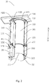
FIG. 3 is a schematic three-dimensional view of an air intake and exhaust assembly according to an embodiment of the present disclosure; and -
FIG. 4 is a schematic three-dimensional view of a packaged air conditioner according to an embodiment of the present disclosure. -
- 10 air intake and exhaust assembly; 20 outdoor heat exchange assembly; 21 outdoor heat exchanger; 22 air exhaust volute; 23 air outlet; 30 air inlet; 40 rear panel;
- 100 air exhaust pipe; 110 air exhaust channel; 120 first joint;
- 200 connecting pipe; 210 first installation port; 211 first buckle; 220 flange;
- 300 air intake pipe; 310 air intake channel; 320 second installation port; 321 second buckle; 330 second joint;
- 400 sealing plate; 410 air intake hole; 420 fixing ring; 421 air exhaust hole; and 430 connecting rib.
- Embodiments of the present disclosure are described below in detail, illustrations of which are shown in the accompanying drawings, where identical or similar reference numerals denote identical or similar elements or elements having the same or similar functions. The embodiments described below by reference to the accompanying drawings are exemplary and are intended only to explain the present disclosure and are not to be construed as limiting the present disclosure.
- In the description of the present disclosure, it should be understood that any orientation/position related description, such as the orientational or positional relationship, such as, up, down, left, right, front, rear, and the like is based on the orientational or positional relationship shown in the accompanying drawings, is only for the purpose of facilitating the description of the present disclosure and simplifying the description, and does not indicate or imply that the device or element indicated or implied must have a specific azimuth, be constructed and operated in a specific orientation or position, and therefore shall not be understood as a limitation to the present disclosure.
- In the description of the present disclosure, several means one or more, and multiple or plurality means more than two. A description of "first" and "second" are for the purpose of distinguishing the technical features, and shall not be understood as indicating or implying relative importance or implying the number of indicated technical features or implying the order of indicated technical features.
- In the description of the present disclosure, words such as setup, installation and connection shall be understood in a broad sense unless otherwise expressly limited, and a person skilled in the art may reasonably determine the specific meaning of the above words in the present disclosure with reference to the context of the technical scheme.
- With reference to
FIG. 1 , an air intake andexhaust assembly 10 according to an embodiment of the present disclosure is applied to a packaged air conditioner employing a dual-air-pipe structure. The air intake andexhaust assembly 10 is connected to an outdoorheat exchange assembly 20 of the packaged air conditioner. The outdoorheat exchange assembly 20 includes anoutdoor heat exchanger 21 and anair exhaust volute 22. One of the air pipes of the air intake andexhaust assembly 10 guides outdoor air to enter from anair inlet 30 of the packaged air conditioner. After the air exchanges heat through theoutdoor heat exchanger 21, the air exhaust volute 22 discharges the air after heat exchange to outdoors through the other air pipe of the air intake andexhaust assembly 10, thus realizing a heat exchange process of the packaged air conditioner. - With reference to
FIG. 1 andFIG. 2 , the air intake andexhaust assembly 10 according to an embodiment of the present disclosure includes anair exhaust pipe 100 and a connectingpipe 200, where anair exhaust channel 110 is provided in theair exhaust pipe 100, one end of the connectingpipe 200 is connected to a lower end of theair exhaust pipe 100 and the other end of the connecting pipe is connected to theair exhaust volute 22, such that theair exhaust channel 110 is communicated with anair outlet 23 of theair exhaust volute 22. It should be noted that the connectingpipe 200 is connected to theair exhaust pipe 100 and the air exhaust volute to form the sealedair exhaust channel 110, which avoids air leakage on a path of exhausting air of theair exhaust channel 110, and ensures that all the air exhausted from theair outlet 23 of theair exhaust volute 22 can be exhausted outdoors through theair exhaust pipe 100. - With reference to
FIG. 1 andFIG. 2 , the air intake andexhaust assembly 10 according to an embodiment of the present disclosure also includes anair intake pipe 300, where theair intake pipe 300 is arranged around theair exhaust pipe 100, anair intake channel 310 is provided between an inner wall of theair intake pipe 300 and an outer wall of theair exhaust pipe 100, and theair intake channel 310 is communicated with theair inlet 30 of the packaged air conditioner, thus forming the sealedair intake channel 310, such that theair intake channel 310 and theair exhaust channel 110 are isolated from each other, which avoids heat exchange between theair intake channel 310 and theair exhaust channel 110 to affect a heat exchange efficiency of the packaged air conditioner. Moreover, the connectingpipe 200 makes connection between theair exhaust pipe 100 and the air exhaust volute more reliable, thus improving a sealing performance of theair exhaust channel 110, and further avoiding air crossing between theintake duct 310 and theexhaust duct 110, thus theair intake channel 310, the outdoorheat exchange assembly 20 and theair exhaust channel 110 are connected to form a sealed heat exchange duct, improving a heat exchange effect between the packaged air conditioner and an outdoor environment, and improving an energy efficiency of the packaged air conditioner. Moreover, the air intake and exhaust assembly is simpler and more convenient to assemble. - It should be further illustrated that the air intake and
exhaust assembly 10 according to the embodiment of the present disclosure forms a dual-air-pipe structure by providing theair exhaust pipe 100 and theair intake pipe 300 arranged around theair exhaust pipe 100. Compared with a dual-air-pipe structure composed of two separate independent air pipes, the air intake andexhaust assembly 10 according to the embodiment of the present disclosure has a simple and aesthetically favorable structure, which is convenient for users to install and adjust the dual-air-pipe structure, and improves user experience. Moreover, the packaged air conditioner employing the dual-air-pipe structure can realize whole house cooling or heating, and improve the heat exchange efficiency of the packaged air conditioner. - With reference to
FIG. 2 , in some embodiments, one end of the connectingpipe 200 facing theair exhaust pipe 100 is provided with afirst installation port 210, and the lower end of theair exhaust pipe 100 is provided with afirst joint 120 matching thefirst installation port 210. Specifically, thefirst joint 120 is installed at the lower end of theair exhaust pipe 100, and thefirst joint 120 and thefirst installation port 210 may be fixedly connected by buckle connection, screw connection, etc., which will not be specifically limited here. - In some embodiments, the
first installation port 210 is provided with a plurality offirst buckles 211 at intervals along a circumferential direction, and the plurality offirst buckles 211 are clamped with thefirst joint 120, which is convenient to install and disassemble and has a stable connection structure by using the clamping manner. It may be understood that a number of thefirst buckle 211 may be set to be one, two, three or more than three. When the number of thefirst buckle 211 is set to be multiple, the multiplefirst buckles 211 are uniformly distributed on thefirst installation port 210, and the number of thefirst buckle 211 may be designed according to different sizes ofair exhaust pipes 100 adopted by the packaged air conditioner in actual production. In addition, the plurality offirst buckles 211 may be designed to be clamped with an outer wall of the first joint 120 (with reference toFIG. 2 ), and may also be designed to be clamped with an inner wall of thefirst joint 120, so as to realize sealing assembly of a joint between theair exhaust pipe 100 and the connectingpipe 200. - It is also illustrated that a lower end of the connecting
pipe 200 is connected to an upper end of the air exhaust volute 22, such that theair outlet 23 of theair exhaust volute 22 is in sealed communication with theair exhaust channel 110, which prevents the air after heat exchange in theair exhaust channel 110 from leaking outside. Specifically, the lower end of the connectingpipe 200 is provided with aflange 220 along a circumferential direction, and theflange 220 abuts against theair outlet 23 of theair exhaust volute 22, thereby further avoiding air crossing between theair intake channel 310 and theair exhaust channel 110 at a joint between the connectingpipe 200 and theair exhaust volute 22. - With reference to
FIG. 1 andFIG. 2 , in some embodiments, theair inlet 30 is provided with asecond installation port 320, and one end of theair intake pipe 300 facing theair inlet 30 is provided with a second joint 330 matching thesecond installation port 320. Specifically, the second joint 330 is installed at the lower end of theair intake pipe 300, and the second joint 330 and thesecond installation port 320 may be fixedly connected by buckle connection, screw connection, etc., which will not be specifically limited here. - In some embodiments, with reference to
FIG. 2 andFIG. 4 , thesecond installation port 320 is provided with a plurality ofsecond buckles 321 at intervals along the circumferential direction, and the plurality ofsecond buckles 321 are clamped with the second joint 330, which is convenient to install and disassemble and has a stable connection structure by using a clamping mechanism. It may be understood that a number of thesecond buckle 321 may be set to be one, two, three or more than three. When the number of thesecond buckle 321 is set to be multiple, the multiplesecond buckles 321 are uniformly distributed on thesecond installation port 320, and the number of thesecond buckle 321 may be designed according to different sizes ofair intake pipes 300 adopted by the packaged air conditioner in actual production. In addition, the plurality ofsecond buckles 321 may be designed to be clamped with an outer wall of the second joint 330, and may also be designed to be clamped with an inner wall of the second joint 330, and theair inlet 30 may be arranged on arear panel 40 of the packaged air conditioner and faces upwards, so as to realize sealing assembly of theair intake pipe 300 and therear panel 40 of the packaged air conditioner to avoid air leakage between theair intake channel 310 and the external environment. - With reference to
FIG. 2 andFIG. 3 , in some embodiments, a sealingplate 400 is further included, where the sealingplate 400 is provided with anair intake hole 410, and theair intake hole 410 is connected to one end of theair intake pipe 300 away from theair inlet 30, such that the sealingplate 400 is fixedly connected to theair intake pipe 300, such that a user can realize synchronous operation of theair intake pipe 300 by operating the sealingplate 400, which is convenient for the user to stretch and install or contract and fold theair intake pipe 300, and improves a usability of theair intake pipe 300. In addition, it is also convenient for the user to stretch or fold theair exhaust pipe 100 through theair intake hole 410. - In some embodiments, with reference to
FIG. 2 andFIG. 3 , the sealingplate 400 also includes a fixingring 420. The fixingring 420 is arranged in theair intake hole 410 and defines anair exhaust hole 421, theair exhaust hole 421 is connected to one end of theair exhaust pipe 100 away from theair outlet 23, the sealingplate 400 and the fixingring 420 fix theair intake pipe 300 with theair exhaust pipe 100, and a connectingrib 430 is arranged between the fixingring 420 and the sealingplate 400, such that the sealingplate 400 and the fixingring 420 are integrally arranged, such that the user can synchronously stretch and install or contract and fold theair intake pipe 300 and theair exhaust pipe 100 while operating the sealingplate 400, which is convenient for the user to integrally stretch and contract the air intake andexhaust assembly 10, thus improving an efficiency of installation and disassembly of the air intake andexhaust assembly 10 and further improving a usability of the air intake andexhaust assembly 10. It is also illustrated that the sealingplate 400, the fixingring 420 and the connectingrib 430 may be formed by integral injection molding, which are convenient to process and more stable in structure. - With reference to
FIG. 3 , in some embodiments, a plurality of connectingribs 430 are provided, and the plurality of connectingribs 430 are arranged at intervals along a circumferential direction of the fixingring 420, which improves a stability of the connection between the fixingring 420 and the sealingplate 400, improves a structural strength of the sealingplate 400, and further prolongs a service life of the air intake andexhaust assembly 10. - With reference to
FIG. 1 andFIG. 3 , in some embodiments, theair exhaust pipe 100, the connectingpipe 200 and theair intake pipe 300 are all cylindrical, which are convenient to process, assemble and use. It should be noted that corrugated hoses may be used as theair exhaust pipe 100 and theair intake pipe 300, which have good flexibility, light weight and good durability and are convenient to contract and fold. - With reference to
FIG. 4 , a packaged air conditioner according to an embodiment of the present disclosure includes the air intake andexhaust assembly 10 according to the above embodiments. According to the packaged air conditioner of this embodiment, a dual-air-pipe structure is formed by arranging theair exhaust pipe 100 and theair intake pipe 300 arranged around theair exhaust pipe 100 in the air intake andexhaust assembly 10, which is simple and aesthetically favorable in structure, is convenient for users to install and adjust the air intake andexhaust assembly 10, and improves the user experience. With reference toFIG. 1 , in the packaged air conditioner according to the embodiment of the present disclosure, theair intake channel 310 is provided between theair intake pipe 300 and theair exhaust pipe 100, such that theair intake channel 310 is communicated with theair inlet 30 of the packaged air conditioner to transfer outdoor air to theoutdoor heat exchanger 21; theair exhaust channel 110 is provided in theair exhaust pipe 100 and connected to theair exhaust volute 22 through the connectingpipe 200, such that theair outlet 23 of theair exhaust volute 22 is communicated with theair exhaust channel 110 to discharge the air after heat exchange outdoors, thereby forming a sealed heat exchange duct and improving the heat exchange effect between the packaged air conditioner and the outdoor environment; and the connectingpipe 200 makes the connection between theair exhaust pipe 100 and theair exhaust volute 22 more reliable, improves a sealing performance of theair exhaust channel 110, avoids air crossing between theair intake channel 310 and theair exhaust channel 110, and improves the energy efficiency of the packaged air conditioner. - The embodiments of the present disclosure have been described in detail above with reference to the accompanying drawings, but the present disclosure is not limited to the embodiments described above, and various changes may be made without departing from the purposes of the present disclosure within the scope of knowledge possessed by those of ordinary skill in the art.
Claims (10)
- An air intake and exhaust assembly for a packaged air conditioner, comprising:an air exhaust pipe, an air exhaust channel is defined in the air exhaust pipe;a connecting pipe, wherein an end of the connecting pipe is connected to a lower end of the air exhaust pipe and an other end of the connecting pipe is connected to an air exhaust volute of the packaged air conditioner, such that the air exhaust channel is communicated with an air outlet of the air exhaust volute;an air intake pipe, wherein the air intake pipe is arranged around the air exhaust pipe, an air intake channel is defined between an inner wall of the air intake pipe and an outer wall of the air exhaust pipe, the air intake channel is communicated with an air inlet of the packaged air conditioner.
- The air intake and exhaust assembly according to claim 1, wherein an end of the connecting pipe facing the air exhaust pipe is provided with a first installation port, the lower end of the air exhaust pipe is provided with a first joint , the first joint matching the first installation port.
- The air intake and exhaust assembly according to claim 2, wherein the first installation port is provided with a plurality of first buckles at an interval along a circumferential direction, the plurality of first buckles are snapped to the first joint.
- The air intake and exhaust assembly according to claim 1, wherein the air inlet is provided with a second installation port, an end of the air intake pipe facing the air inlet is provided with a second joint, the second joint matching the second installation port.
- The air intake and exhaust assembly according to claim 4, wherein the second installation port is provided with a plurality of second buckles at an interval along a circumferential direction, the plurality of second buckles are snapped to the second joint.
- The air intake and exhaust assembly according to claim 1, further comprising a sealing plate, wherein the sealing plate is provided with an air intake hole, the air intake hole is connected to an end of the air intake pipe away from the air inlet.
- The air intake and exhaust assembly according to claim 6, wherein the sealing plate further comprises a fixing ring, the fixing ring is arranged in the air intake hole and defines an air exhaust hole, the air exhaust hole is connected to an end of the air exhaust pipe away from the air outlet, a connecting rib is provided between the fixing ring and the sealing plate.
- The air intake and exhaust assembly according to claim 7, wherein a plurality of connecting ribs are provided, and the plurality of connecting ribs are arranged at an interval along a circumferential direction of the fixing ring.
- The air intake and exhaust assembly according to claim 1, wherein the air exhaust pipe, the connecting pipe and the air intake pipe are cylindrical.
- A packaged air conditioner, comprising an air intake and exhaust assembly according to any one of claims 1 to 9.
Applications Claiming Priority (3)
| Application Number | Priority Date | Filing Date | Title |
|---|---|---|---|
| CN202010161781.8A CN111237887A (en) | 2020-03-10 | 2020-03-10 | Air intake and exhaust components and integrated air conditioning |
| CN202020288838.6U CN211667920U (en) | 2020-03-10 | 2020-03-10 | Air intake and exhaust assembly and integral air conditioner |
| PCT/CN2020/088358 WO2021179421A1 (en) | 2020-03-10 | 2020-04-30 | Air inlet and exhaust assembly, and integrated air conditioner |
Publications (4)
| Publication Number | Publication Date |
|---|---|
| EP3907434A1 true EP3907434A1 (en) | 2021-11-10 |
| EP3907434A4 EP3907434A4 (en) | 2022-04-13 |
| EP3907434C0 EP3907434C0 (en) | 2024-08-07 |
| EP3907434B1 EP3907434B1 (en) | 2024-08-07 |
Family
ID=77663207
Family Applications (1)
| Application Number | Title | Priority Date | Filing Date |
|---|---|---|---|
| EP20914758.6A Active EP3907434B1 (en) | 2020-03-10 | 2020-04-30 | Air inlet and exhaust assembly, and integrated air conditioner |
Country Status (3)
| Country | Link |
|---|---|
| US (1) | US12007140B2 (en) |
| EP (1) | EP3907434B1 (en) |
| CA (1) | CA3126372A1 (en) |
Family Cites Families (12)
| Publication number | Priority date | Publication date | Assignee | Title |
|---|---|---|---|---|
| DE1454560A1 (en) | 1964-01-31 | 1969-03-20 | Alvaro Frigerio | Device for improving the air or air conditioning of rooms |
| US3712649A (en) * | 1965-10-11 | 1973-01-23 | D Martin | Apparatus for supporting and retaining low density webs |
| CN2211032Y (en) | 1995-01-20 | 1995-10-25 | 沈志坚 | Air conditioner |
| CN2779294Y (en) | 2005-04-18 | 2006-05-10 | 倪伯杨 | Wall tubing for air-conditioner |
| JP4886617B2 (en) | 2007-06-26 | 2012-02-29 | オリオン機械株式会社 | Cooling system |
| JP2008051498A (en) | 2007-11-12 | 2008-03-06 | Mitsubishi Electric Corp | Air conditioner and separate type air conditioner |
| TWM371855U (en) | 2009-03-13 | 2010-01-01 | Mao-Tsai Ku | Venting pipe for air conditioner |
| FR3010015B1 (en) * | 2013-09-05 | 2015-09-18 | Valeo Vision | LUMINOUS ASSEMBLY COMPRISING AN OPTICAL DEVICE INTEGRATED IN A CLIMATE ASSEMBLY OF THE MOTOR VEHICLE |
| CN204830382U (en) * | 2015-08-13 | 2015-12-02 | 苏州格兰斯柯光电科技有限公司 | Exhaust pipe for air purifier |
| CN209068701U (en) | 2018-11-07 | 2019-07-05 | 珠海格力电器股份有限公司 | Pipe connection joint, pipe connection structure and air conditioner indoor unit |
| CN110822561A (en) | 2019-11-29 | 2020-02-21 | 广东美的制冷设备有限公司 | Air intake and exhaust assembly and integral air conditioner |
| CN209926557U (en) | 2019-12-11 | 2020-01-10 | 杭州卓尔净化工程有限公司 | An exhaust device for a central air-conditioning system |
-
2020
- 2020-04-30 EP EP20914758.6A patent/EP3907434B1/en active Active
- 2020-04-30 US US17/430,126 patent/US12007140B2/en active Active
- 2020-04-30 CA CA3126372A patent/CA3126372A1/en active Pending
Also Published As
| Publication number | Publication date |
|---|---|
| US20220307723A1 (en) | 2022-09-29 |
| EP3907434A4 (en) | 2022-04-13 |
| CA3126372A1 (en) | 2021-09-10 |
| EP3907434C0 (en) | 2024-08-07 |
| US12007140B2 (en) | 2024-06-11 |
| EP3907434B1 (en) | 2024-08-07 |
Similar Documents
| Publication | Publication Date | Title |
|---|---|---|
| WO2021179421A1 (en) | Air inlet and exhaust assembly, and integrated air conditioner | |
| US9151512B2 (en) | Ventilation system | |
| WO2020124758A1 (en) | Duct type air conditioner | |
| WO2020093571A1 (en) | Connecting pipe structure and air conditioner indoor unit having same | |
| CN209689057U (en) | Air duct components of air conditioner indoor unit and air conditioner indoor unit | |
| CN111237886A (en) | Air intake and exhaust assembly and integral air conditioner | |
| EP3916313A1 (en) | Air feeding and exhausting assembly, and integral air conditioner | |
| CN215523553U (en) | Hydraulic module and air conditioner outdoor unit | |
| WO2017206305A1 (en) | Fuel gas water heater and heat exchanger for use in fuel gas water heater | |
| CN106907795A (en) | Wall-hanging air conditioner all-in-one | |
| EP3907434A1 (en) | Air inlet and exhaust assembly, and integrated air conditioner | |
| EP4269902A2 (en) | A heat pump unit and a split heat pump water heater | |
| CN111237887A (en) | Air intake and exhaust components and integrated air conditioning | |
| CN211667920U (en) | Air intake and exhaust assembly and integral air conditioner | |
| CN208253799U (en) | Outdoor pipe connecting structure and air conditioner indoor unit with same | |
| CN211695168U (en) | Air intake and exhaust assembly and integral air conditioner | |
| CN110410876B (en) | Air conditioner outdoor unit and air conditioner | |
| WO2021179423A1 (en) | Air supply and discharging assembly and packaged air conditioner | |
| CN206626700U (en) | Wall-hanging air conditioner all-in-one | |
| CN206771553U (en) | Wall-hanging air conditioner all-in-one | |
| CA3125719C (en) | Air intake and exhaust assembly and packaged air conditioner | |
| CN212005974U (en) | Joint assembly, air intake and exhaust assembly and integrated air conditioner | |
| CN116123621A (en) | Outdoor unit and air conditioner | |
| CN222230827U (en) | Air outlet component for kitchen air conditioner and kitchen air conditioner | |
| CN221593090U (en) | Basement condensation treatment device |
Legal Events
| Date | Code | Title | Description |
|---|---|---|---|
| STAA | Information on the status of an ep patent application or granted ep patent |
Free format text: STATUS: UNKNOWN |
|
| STAA | Information on the status of an ep patent application or granted ep patent |
Free format text: STATUS: THE INTERNATIONAL PUBLICATION HAS BEEN MADE |
|
| PUAI | Public reference made under article 153(3) epc to a published international application that has entered the european phase |
Free format text: ORIGINAL CODE: 0009012 |
|
| STAA | Information on the status of an ep patent application or granted ep patent |
Free format text: STATUS: REQUEST FOR EXAMINATION WAS MADE |
|
| 17P | Request for examination filed |
Effective date: 20210727 |
|
| AK | Designated contracting states |
Kind code of ref document: A1 Designated state(s): AL AT BE BG CH CY CZ DE DK EE ES FI FR GB GR HR HU IE IS IT LI LT LU LV MC MK MT NL NO PL PT RO RS SE SI SK SM TR |
|
| RIN1 | Information on inventor provided before grant (corrected) |
Inventor name: ZHAO, ELI Inventor name: XING, ZHIGANG |
|
| A4 | Supplementary search report drawn up and despatched |
Effective date: 20220314 |
|
| RIC1 | Information provided on ipc code assigned before grant |
Ipc: F16L 9/19 20060101ALI20220308BHEP Ipc: F24F 13/02 20060101ALI20220308BHEP Ipc: F24F 1/028 20190101AFI20220308BHEP |
|
| DAV | Request for validation of the european patent (deleted) | ||
| DAX | Request for extension of the european patent (deleted) | ||
| GRAP | Despatch of communication of intention to grant a patent |
Free format text: ORIGINAL CODE: EPIDOSNIGR1 |
|
| STAA | Information on the status of an ep patent application or granted ep patent |
Free format text: STATUS: GRANT OF PATENT IS INTENDED |
|
| RIC1 | Information provided on ipc code assigned before grant |
Ipc: F16L 9/19 20060101ALI20240515BHEP Ipc: F24F 13/02 20060101ALI20240515BHEP Ipc: F24F 1/028 20190101AFI20240515BHEP |
|
| INTG | Intention to grant announced |
Effective date: 20240607 |
|
| GRAS | Grant fee paid |
Free format text: ORIGINAL CODE: EPIDOSNIGR3 |
|
| GRAA | (expected) grant |
Free format text: ORIGINAL CODE: 0009210 |
|
| STAA | Information on the status of an ep patent application or granted ep patent |
Free format text: STATUS: THE PATENT HAS BEEN GRANTED |
|
| AK | Designated contracting states |
Kind code of ref document: B1 Designated state(s): AL AT BE BG CH CY CZ DE DK EE ES FI FR GB GR HR HU IE IS IT LI LT LU LV MC MK MT NL NO PL PT RO RS SE SI SK SM TR |
|
| REG | Reference to a national code |
Ref country code: GB Ref legal event code: FG4D |
|
| REG | Reference to a national code |
Ref country code: CH Ref legal event code: EP |
|
| REG | Reference to a national code |
Ref country code: DE Ref legal event code: R096 Ref document number: 602020035555 Country of ref document: DE |
|
| REG | Reference to a national code |
Ref country code: IE Ref legal event code: FG4D |
|
| U01 | Request for unitary effect filed |
Effective date: 20240820 |
|
| U07 | Unitary effect registered |
Designated state(s): AT BE BG DE DK EE FI FR IT LT LU LV MT NL PT RO SE SI Effective date: 20240902 |
|
| PG25 | Lapsed in a contracting state [announced via postgrant information from national office to epo] |
Ref country code: NO Free format text: LAPSE BECAUSE OF FAILURE TO SUBMIT A TRANSLATION OF THE DESCRIPTION OR TO PAY THE FEE WITHIN THE PRESCRIBED TIME-LIMIT Effective date: 20241107 |
|
| PG25 | Lapsed in a contracting state [announced via postgrant information from national office to epo] |
Ref country code: GR Free format text: LAPSE BECAUSE OF FAILURE TO SUBMIT A TRANSLATION OF THE DESCRIPTION OR TO PAY THE FEE WITHIN THE PRESCRIBED TIME-LIMIT Effective date: 20241108 Ref country code: PL Free format text: LAPSE BECAUSE OF FAILURE TO SUBMIT A TRANSLATION OF THE DESCRIPTION OR TO PAY THE FEE WITHIN THE PRESCRIBED TIME-LIMIT Effective date: 20240807 |
|
| PG25 | Lapsed in a contracting state [announced via postgrant information from national office to epo] |
Ref country code: IS Free format text: LAPSE BECAUSE OF FAILURE TO SUBMIT A TRANSLATION OF THE DESCRIPTION OR TO PAY THE FEE WITHIN THE PRESCRIBED TIME-LIMIT Effective date: 20241207 |
|
| PG25 | Lapsed in a contracting state [announced via postgrant information from national office to epo] |
Ref country code: HR Free format text: LAPSE BECAUSE OF FAILURE TO SUBMIT A TRANSLATION OF THE DESCRIPTION OR TO PAY THE FEE WITHIN THE PRESCRIBED TIME-LIMIT Effective date: 20240807 |
|
| PG25 | Lapsed in a contracting state [announced via postgrant information from national office to epo] |
Ref country code: ES Free format text: LAPSE BECAUSE OF FAILURE TO SUBMIT A TRANSLATION OF THE DESCRIPTION OR TO PAY THE FEE WITHIN THE PRESCRIBED TIME-LIMIT Effective date: 20240807 Ref country code: RS Free format text: LAPSE BECAUSE OF FAILURE TO SUBMIT A TRANSLATION OF THE DESCRIPTION OR TO PAY THE FEE WITHIN THE PRESCRIBED TIME-LIMIT Effective date: 20241107 |
|
| PG25 | Lapsed in a contracting state [announced via postgrant information from national office to epo] |
Ref country code: RS Free format text: LAPSE BECAUSE OF FAILURE TO SUBMIT A TRANSLATION OF THE DESCRIPTION OR TO PAY THE FEE WITHIN THE PRESCRIBED TIME-LIMIT Effective date: 20241107 Ref country code: PL Free format text: LAPSE BECAUSE OF FAILURE TO SUBMIT A TRANSLATION OF THE DESCRIPTION OR TO PAY THE FEE WITHIN THE PRESCRIBED TIME-LIMIT Effective date: 20240807 Ref country code: NO Free format text: LAPSE BECAUSE OF FAILURE TO SUBMIT A TRANSLATION OF THE DESCRIPTION OR TO PAY THE FEE WITHIN THE PRESCRIBED TIME-LIMIT Effective date: 20241107 Ref country code: IS Free format text: LAPSE BECAUSE OF FAILURE TO SUBMIT A TRANSLATION OF THE DESCRIPTION OR TO PAY THE FEE WITHIN THE PRESCRIBED TIME-LIMIT Effective date: 20241207 Ref country code: HR Free format text: LAPSE BECAUSE OF FAILURE TO SUBMIT A TRANSLATION OF THE DESCRIPTION OR TO PAY THE FEE WITHIN THE PRESCRIBED TIME-LIMIT Effective date: 20240807 Ref country code: GR Free format text: LAPSE BECAUSE OF FAILURE TO SUBMIT A TRANSLATION OF THE DESCRIPTION OR TO PAY THE FEE WITHIN THE PRESCRIBED TIME-LIMIT Effective date: 20241108 Ref country code: ES Free format text: LAPSE BECAUSE OF FAILURE TO SUBMIT A TRANSLATION OF THE DESCRIPTION OR TO PAY THE FEE WITHIN THE PRESCRIBED TIME-LIMIT Effective date: 20240807 |
|
| PG25 | Lapsed in a contracting state [announced via postgrant information from national office to epo] |
Ref country code: SM Free format text: LAPSE BECAUSE OF FAILURE TO SUBMIT A TRANSLATION OF THE DESCRIPTION OR TO PAY THE FEE WITHIN THE PRESCRIBED TIME-LIMIT Effective date: 20240807 |
|
| PG25 | Lapsed in a contracting state [announced via postgrant information from national office to epo] |
Ref country code: CZ Free format text: LAPSE BECAUSE OF FAILURE TO SUBMIT A TRANSLATION OF THE DESCRIPTION OR TO PAY THE FEE WITHIN THE PRESCRIBED TIME-LIMIT Effective date: 20240807 |
|
| PG25 | Lapsed in a contracting state [announced via postgrant information from national office to epo] |
Ref country code: SK Free format text: LAPSE BECAUSE OF FAILURE TO SUBMIT A TRANSLATION OF THE DESCRIPTION OR TO PAY THE FEE WITHIN THE PRESCRIBED TIME-LIMIT Effective date: 20240807 |
|
| U20 | Renewal fee for the european patent with unitary effect paid |
Year of fee payment: 6 Effective date: 20250422 |
|
| PLBE | No opposition filed within time limit |
Free format text: ORIGINAL CODE: 0009261 |
|
| STAA | Information on the status of an ep patent application or granted ep patent |
Free format text: STATUS: NO OPPOSITION FILED WITHIN TIME LIMIT |
|
| 26N | No opposition filed |
Effective date: 20250508 |
|
| REG | Reference to a national code |
Ref country code: CH Ref legal event code: H13 Free format text: ST27 STATUS EVENT CODE: U-0-0-H10-H13 (AS PROVIDED BY THE NATIONAL OFFICE) Effective date: 20251125 |
|
| PG25 | Lapsed in a contracting state [announced via postgrant information from national office to epo] |
Ref country code: MC Free format text: LAPSE BECAUSE OF FAILURE TO SUBMIT A TRANSLATION OF THE DESCRIPTION OR TO PAY THE FEE WITHIN THE PRESCRIBED TIME-LIMIT Effective date: 20240807 |
|
| GBPC | Gb: european patent ceased through non-payment of renewal fee |
Effective date: 20250430 |
|
| PG25 | Lapsed in a contracting state [announced via postgrant information from national office to epo] |
Ref country code: GB Free format text: LAPSE BECAUSE OF NON-PAYMENT OF DUE FEES Effective date: 20250430 |
|
| PG25 | Lapsed in a contracting state [announced via postgrant information from national office to epo] |
Ref country code: CH Free format text: LAPSE BECAUSE OF NON-PAYMENT OF DUE FEES Effective date: 20250430 |
|
| PG25 | Lapsed in a contracting state [announced via postgrant information from national office to epo] |
Ref country code: IE Free format text: LAPSE BECAUSE OF NON-PAYMENT OF DUE FEES Effective date: 20250430 |