EP3907390A1 - Stromerzeugungsanlage - Google Patents
Stromerzeugungsanlage Download PDFInfo
- Publication number
- EP3907390A1 EP3907390A1 EP20382368.7A EP20382368A EP3907390A1 EP 3907390 A1 EP3907390 A1 EP 3907390A1 EP 20382368 A EP20382368 A EP 20382368A EP 3907390 A1 EP3907390 A1 EP 3907390A1
- Authority
- EP
- European Patent Office
- Prior art keywords
- compressed air
- power generation
- storage
- thermal energy
- working fluid
- Prior art date
- Legal status (The legal status is an assumption and is not a legal conclusion. Google has not performed a legal analysis and makes no representation as to the accuracy of the status listed.)
- Withdrawn
Links
Images


Classifications
-
- F—MECHANICAL ENGINEERING; LIGHTING; HEATING; WEAPONS; BLASTING
- F02—COMBUSTION ENGINES; HOT-GAS OR COMBUSTION-PRODUCT ENGINE PLANTS
- F02C—GAS-TURBINE PLANTS; AIR INTAKES FOR JET-PROPULSION PLANTS; CONTROLLING FUEL SUPPLY IN AIR-BREATHING JET-PROPULSION PLANTS
- F02C6/00—Plural gas-turbine plants; Combinations of gas-turbine plants with other apparatus; Adaptations of gas- turbine plants for special use
- F02C6/14—Gas-turbine plants having means for storing energy, e.g. for meeting peak loads
- F02C6/16—Gas-turbine plants having means for storing energy, e.g. for meeting peak loads for storing compressed air
-
- F—MECHANICAL ENGINEERING; LIGHTING; HEATING; WEAPONS; BLASTING
- F01—MACHINES OR ENGINES IN GENERAL; ENGINE PLANTS IN GENERAL; STEAM ENGINES
- F01K—STEAM ENGINE PLANTS; STEAM ACCUMULATORS; ENGINE PLANTS NOT OTHERWISE PROVIDED FOR; ENGINES USING SPECIAL WORKING FLUIDS OR CYCLES
- F01K3/00—Plants characterised by the use of steam or heat accumulators, or intermediate steam heaters, therein
- F01K3/12—Plants characterised by the use of steam or heat accumulators, or intermediate steam heaters, therein having two or more accumulators
-
- F—MECHANICAL ENGINEERING; LIGHTING; HEATING; WEAPONS; BLASTING
- F01—MACHINES OR ENGINES IN GENERAL; ENGINE PLANTS IN GENERAL; STEAM ENGINES
- F01K—STEAM ENGINE PLANTS; STEAM ACCUMULATORS; ENGINE PLANTS NOT OTHERWISE PROVIDED FOR; ENGINES USING SPECIAL WORKING FLUIDS OR CYCLES
- F01K3/00—Plants characterised by the use of steam or heat accumulators, or intermediate steam heaters, therein
- F01K3/18—Plants characterised by the use of steam or heat accumulators, or intermediate steam heaters, therein having heaters
-
- F—MECHANICAL ENGINEERING; LIGHTING; HEATING; WEAPONS; BLASTING
- F02—COMBUSTION ENGINES; HOT-GAS OR COMBUSTION-PRODUCT ENGINE PLANTS
- F02C—GAS-TURBINE PLANTS; AIR INTAKES FOR JET-PROPULSION PLANTS; CONTROLLING FUEL SUPPLY IN AIR-BREATHING JET-PROPULSION PLANTS
- F02C1/00—Gas-turbine plants characterised by the use of hot gases or unheated pressurised gases, as the working fluid
- F02C1/04—Gas-turbine plants characterised by the use of hot gases or unheated pressurised gases, as the working fluid the working fluid being heated indirectly
- F02C1/05—Gas-turbine plants characterised by the use of hot gases or unheated pressurised gases, as the working fluid the working fluid being heated indirectly characterised by the type or source of heat, e.g. using nuclear or solar energy
-
- F—MECHANICAL ENGINEERING; LIGHTING; HEATING; WEAPONS; BLASTING
- F03—MACHINES OR ENGINES FOR LIQUIDS; WIND, SPRING, OR WEIGHT MOTORS; PRODUCING MECHANICAL POWER OR A REACTIVE PROPULSIVE THRUST, NOT OTHERWISE PROVIDED FOR
- F03G—SPRING, WEIGHT, INERTIA OR LIKE MOTORS; MECHANICAL-POWER PRODUCING DEVICES OR MECHANISMS, NOT OTHERWISE PROVIDED FOR OR USING ENERGY SOURCES NOT OTHERWISE PROVIDED FOR
- F03G6/00—Devices for producing mechanical power from solar energy
- F03G6/06—Devices for producing mechanical power from solar energy with solar energy concentrating means
- F03G6/064—Devices for producing mechanical power from solar energy with solar energy concentrating means having a gas turbine cycle, i.e. compressor and gas turbine combination
-
- F—MECHANICAL ENGINEERING; LIGHTING; HEATING; WEAPONS; BLASTING
- F03—MACHINES OR ENGINES FOR LIQUIDS; WIND, SPRING, OR WEIGHT MOTORS; PRODUCING MECHANICAL POWER OR A REACTIVE PROPULSIVE THRUST, NOT OTHERWISE PROVIDED FOR
- F03G—SPRING, WEIGHT, INERTIA OR LIKE MOTORS; MECHANICAL-POWER PRODUCING DEVICES OR MECHANISMS, NOT OTHERWISE PROVIDED FOR OR USING ENERGY SOURCES NOT OTHERWISE PROVIDED FOR
- F03G6/00—Devices for producing mechanical power from solar energy
- F03G6/06—Devices for producing mechanical power from solar energy with solar energy concentrating means
- F03G6/065—Devices for producing mechanical power from solar energy with solar energy concentrating means having a Rankine cycle
- F03G6/067—Binary cycle plants where the fluid from the solar collector heats the working fluid via a heat exchanger
-
- F—MECHANICAL ENGINEERING; LIGHTING; HEATING; WEAPONS; BLASTING
- F03—MACHINES OR ENGINES FOR LIQUIDS; WIND, SPRING, OR WEIGHT MOTORS; PRODUCING MECHANICAL POWER OR A REACTIVE PROPULSIVE THRUST, NOT OTHERWISE PROVIDED FOR
- F03G—SPRING, WEIGHT, INERTIA OR LIKE MOTORS; MECHANICAL-POWER PRODUCING DEVICES OR MECHANISMS, NOT OTHERWISE PROVIDED FOR OR USING ENERGY SOURCES NOT OTHERWISE PROVIDED FOR
- F03G6/00—Devices for producing mechanical power from solar energy
- F03G6/071—Devices for producing mechanical power from solar energy with energy storage devices
- F03G6/074—Devices for producing mechanical power from solar energy with energy storage devices of the non-thermal type, e.g. springs or batteries
-
- F—MECHANICAL ENGINEERING; LIGHTING; HEATING; WEAPONS; BLASTING
- F05—INDEXING SCHEMES RELATING TO ENGINES OR PUMPS IN VARIOUS SUBCLASSES OF CLASSES F01-F04
- F05D—INDEXING SCHEME FOR ASPECTS RELATING TO NON-POSITIVE-DISPLACEMENT MACHINES OR ENGINES, GAS-TURBINES OR JET-PROPULSION PLANTS
- F05D2220/00—Application
- F05D2220/70—Application in combination with
- F05D2220/72—Application in combination with a steam turbine
-
- F—MECHANICAL ENGINEERING; LIGHTING; HEATING; WEAPONS; BLASTING
- F05—INDEXING SCHEMES RELATING TO ENGINES OR PUMPS IN VARIOUS SUBCLASSES OF CLASSES F01-F04
- F05D—INDEXING SCHEME FOR ASPECTS RELATING TO NON-POSITIVE-DISPLACEMENT MACHINES OR ENGINES, GAS-TURBINES OR JET-PROPULSION PLANTS
- F05D2260/00—Function
- F05D2260/20—Heat transfer, e.g. cooling
- F05D2260/24—Heat transfer, e.g. cooling for draft enhancement in chimneys, using solar or other heat sources
-
- F—MECHANICAL ENGINEERING; LIGHTING; HEATING; WEAPONS; BLASTING
- F05—INDEXING SCHEMES RELATING TO ENGINES OR PUMPS IN VARIOUS SUBCLASSES OF CLASSES F01-F04
- F05D—INDEXING SCHEME FOR ASPECTS RELATING TO NON-POSITIVE-DISPLACEMENT MACHINES OR ENGINES, GAS-TURBINES OR JET-PROPULSION PLANTS
- F05D2260/00—Function
- F05D2260/42—Storage of energy
-
- Y—GENERAL TAGGING OF NEW TECHNOLOGICAL DEVELOPMENTS; GENERAL TAGGING OF CROSS-SECTIONAL TECHNOLOGIES SPANNING OVER SEVERAL SECTIONS OF THE IPC; TECHNICAL SUBJECTS COVERED BY FORMER USPC CROSS-REFERENCE ART COLLECTIONS [XRACs] AND DIGESTS
- Y02—TECHNOLOGIES OR APPLICATIONS FOR MITIGATION OR ADAPTATION AGAINST CLIMATE CHANGE
- Y02B—CLIMATE CHANGE MITIGATION TECHNOLOGIES RELATED TO BUILDINGS, e.g. HOUSING, HOUSE APPLIANCES OR RELATED END-USER APPLICATIONS
- Y02B10/00—Integration of renewable energy sources in buildings
- Y02B10/20—Solar thermal
-
- Y—GENERAL TAGGING OF NEW TECHNOLOGICAL DEVELOPMENTS; GENERAL TAGGING OF CROSS-SECTIONAL TECHNOLOGIES SPANNING OVER SEVERAL SECTIONS OF THE IPC; TECHNICAL SUBJECTS COVERED BY FORMER USPC CROSS-REFERENCE ART COLLECTIONS [XRACs] AND DIGESTS
- Y02—TECHNOLOGIES OR APPLICATIONS FOR MITIGATION OR ADAPTATION AGAINST CLIMATE CHANGE
- Y02E—REDUCTION OF GREENHOUSE GAS [GHG] EMISSIONS, RELATED TO ENERGY GENERATION, TRANSMISSION OR DISTRIBUTION
- Y02E10/00—Energy generation through renewable energy sources
- Y02E10/40—Solar thermal energy, e.g. solar towers
- Y02E10/46—Conversion of thermal power into mechanical power, e.g. Rankine, Stirling or solar thermal engines
-
- Y—GENERAL TAGGING OF NEW TECHNOLOGICAL DEVELOPMENTS; GENERAL TAGGING OF CROSS-SECTIONAL TECHNOLOGIES SPANNING OVER SEVERAL SECTIONS OF THE IPC; TECHNICAL SUBJECTS COVERED BY FORMER USPC CROSS-REFERENCE ART COLLECTIONS [XRACs] AND DIGESTS
- Y02—TECHNOLOGIES OR APPLICATIONS FOR MITIGATION OR ADAPTATION AGAINST CLIMATE CHANGE
- Y02E—REDUCTION OF GREENHOUSE GAS [GHG] EMISSIONS, RELATED TO ENERGY GENERATION, TRANSMISSION OR DISTRIBUTION
- Y02E20/00—Combustion technologies with mitigation potential
- Y02E20/14—Combined heat and power generation [CHP]
-
- Y—GENERAL TAGGING OF NEW TECHNOLOGICAL DEVELOPMENTS; GENERAL TAGGING OF CROSS-SECTIONAL TECHNOLOGIES SPANNING OVER SEVERAL SECTIONS OF THE IPC; TECHNICAL SUBJECTS COVERED BY FORMER USPC CROSS-REFERENCE ART COLLECTIONS [XRACs] AND DIGESTS
- Y02—TECHNOLOGIES OR APPLICATIONS FOR MITIGATION OR ADAPTATION AGAINST CLIMATE CHANGE
- Y02E—REDUCTION OF GREENHOUSE GAS [GHG] EMISSIONS, RELATED TO ENERGY GENERATION, TRANSMISSION OR DISTRIBUTION
- Y02E20/00—Combustion technologies with mitigation potential
- Y02E20/16—Combined cycle power plant [CCPP], or combined cycle gas turbine [CCGT]
-
- Y—GENERAL TAGGING OF NEW TECHNOLOGICAL DEVELOPMENTS; GENERAL TAGGING OF CROSS-SECTIONAL TECHNOLOGIES SPANNING OVER SEVERAL SECTIONS OF THE IPC; TECHNICAL SUBJECTS COVERED BY FORMER USPC CROSS-REFERENCE ART COLLECTIONS [XRACs] AND DIGESTS
- Y02—TECHNOLOGIES OR APPLICATIONS FOR MITIGATION OR ADAPTATION AGAINST CLIMATE CHANGE
- Y02E—REDUCTION OF GREENHOUSE GAS [GHG] EMISSIONS, RELATED TO ENERGY GENERATION, TRANSMISSION OR DISTRIBUTION
- Y02E60/00—Enabling technologies; Technologies with a potential or indirect contribution to GHG emissions mitigation
- Y02E60/16—Mechanical energy storage, e.g. flywheels or pressurised fluids
-
- Y—GENERAL TAGGING OF NEW TECHNOLOGICAL DEVELOPMENTS; GENERAL TAGGING OF CROSS-SECTIONAL TECHNOLOGIES SPANNING OVER SEVERAL SECTIONS OF THE IPC; TECHNICAL SUBJECTS COVERED BY FORMER USPC CROSS-REFERENCE ART COLLECTIONS [XRACs] AND DIGESTS
- Y02—TECHNOLOGIES OR APPLICATIONS FOR MITIGATION OR ADAPTATION AGAINST CLIMATE CHANGE
- Y02E—REDUCTION OF GREENHOUSE GAS [GHG] EMISSIONS, RELATED TO ENERGY GENERATION, TRANSMISSION OR DISTRIBUTION
- Y02E70/00—Other energy conversion or management systems reducing GHG emissions
- Y02E70/30—Systems combining energy storage with energy generation of non-fossil origin
Definitions
- the present invention belongs to the field of energy production plants and, more particularly, to the field of thermal solar power combined cycle plants with thermal energy and compressed air storage systems.
- the energy market favors the peak demand periods with higher energy purchase prices, and keeps the low demand periods, or off-peak demand, in the lower range of prices.
- Another available large-scale energy storage technology are flow batteries, or battery electric storage in general.
- CSP concentrated solar power
- the problem concerning central receiver solar thermal plants is the fact that the solar-to-thermal and the thermal-to-electric conversion efficiencies correlate conversely when upscaling the power plant.
- the solar-to-thermal energy conversion process (heliostat field and solar receiver) works best for small solar fields and low nominal power of the solar receiver.
- the power cycle becomes more efficient and also cheaper per kWe, the higher the power output is. Therefore, when upscaling a central receiver plant, this trade-off needs to be considered and does not allow very high-capacity plants and thus limits the economic competitiveness of CSP central receiver technology.
- the present invention provides an alternative solution for the aforementioned problems, by a power generation plant according to claim 1.
- a power generation plant according to claim 1.
- preferred embodiments of the invention are defined.
- the invention provides a power generation plant, comprising:
- the working fluid will be understood as any fluid which fulfils the requirements of compressibility, heat capacity, density, melting point and other properties which enable the use of the fluid in the heat exchangers, the thermodynamic cycles, as a coolant or as a thermal fluid.
- the second working fluid is air, which is suitable as a working fluid of the topping cycle, it is stable along a wide range of temperatures and can store energy when compressed.
- the fourth working fluid, used in the bottoming Rankine cycle which involves a phase change is steam.
- the low temperature heat exchanger is capable of switching from a series configuration of the third working fluid circuitry during the compressed air heating process (prior to expansion), and a parallel configuration of the third working fluid circuitry during the cooling of the compressed air between the compressor system's stages.
- this configuration switch is achieved by means of selectively operating valves (pressurized ducts) and dampers (atmospheric ducts).
- the arrangement of the heat exchangers and energy storage systems allows for a higher efficiency of the power plant, by recovering the heat produced during the compression of air, and by pre-heating the compressed air prior to the expansion in the topping cycle subsystem. Furthermore, the arrangement of the compressed air storage and the thermal energy storage allow for the storage of electric energy during low demand periods, and the release of the stored energy during peak demand periods, thus adapting the production of energy to the energy demand of the grid.
- the power plant of the invention allows time shifting between Brayton cycle air compression and actual usage of the compressed air in the power cycle.
- the compression of the working fluid can be carried out applying low-price electricity from the grid during high renewable output, as is the case for solar generation or wind power, or coupling the compressor to such solar or/and wind system (hybrid plant layout).
- the conversion efficiency of the power cycle is remarkably increased.
- the compressed air is stored and later released when electric power needs to be produced by the plant, as is the case during high peak demand hours. Then, the pressurized air is drawn from the storage, heated up and expanded in an air turbine.
- the compressed air storage allows using excess generation capacity of the power grid to compress air and store it in an underground cavern or aboveground in man-made vessels.
- this layout provides a renewable power plant, such as a solar power plant, subjected to the drawback of variable power output, with adaptive capabilities that enables it to produce electric power and meet the demand during high peak demand hours.
- a renewable power plant such as a solar power plant
- variable power output with adaptive capabilities that enables it to produce electric power and meet the demand during high peak demand hours.
- the thermal-to-electric energy conversion efficiency of concentrated solar power system is increased compared to the existing power plants. Therefore, the specific cost of the power cycle of the present invention is reduced, so that small and compact power tower plants with high optical efficiency become economically viable.
- the low temperature heat exchanger is further configured to selectively heat with the thermal energy stored in the second thermal energy storage the compressed air upon release from the compressed air storage prior to expansion to turbine inlet pressure to feed the gas turbine subsystem
- the gas turbine subsystem comprises a compound turbine with a high pressure part and a low pressure part, and a reheat heat exchanger configured to reheat the air with the first working fluid before entering the low pressure part.
- the reheating of the air after the high pressure part of the gas turbine subsystem increases the energy of the air flow, and thus improves the efficiency and output of the gas turbine subsystem.
- the boiler of the steam turbine subsystem is further configured to heat the fourth working fluid with the remaining thermal energy of the outlet flow of the reheat heat exchanger.
- feeding the excess heat of the reheat heat exchanger increases the energy transferred to the fourth working fluid, and thus improves the efficiency and output of the steam turbine subsystem.
- the first heat storage is a high temperature thermocline storage.
- the high temperature storage provides a storage with a high energy density; the thermocline or stratified storage provides a cost effective storage of thermal energy.
- the second heat storage is a low temperature thermocline storage.
- the low temperature thermocline storage provides a long lasting storage of thermal energy recovered from the compressor system.
- the compressed air storage comprises a pressure vessel configured to store the compressed air.
- pressure vessel should be understood as any kind of receptacle capable of storing a fluid, in particular a gas, at a different pressure in respect to the atmospheric pressure.
- the pressure vessel provides a reliable and long lasting storage of energy in the form of compressed air, which can be used on demand.
- the pressure vessel of the compressed air storage is immersed in water.
- the immersion of the pressure vessel in a fluid allows for the balance of the pressure of the fluid with the hydrostatic pressure, thus enabling the use of inexpensive, low resistance materials for the pressure vessel.
- the pressure vessel of the compressed air storage is configured as a geological formation, such as a cave, configured to store the compressed air.
- a natural or artificial geological formation is used as a pressure vessel.
- the geological formation is a mine; in other embodiments, the geological formation is a natural cave.
- the compressor system is configured to receive a power supply from a renewable energy power plant.
- a renewable energy power source such as wind power, solar power, hydro power or a combination thereof, for the power supply of the compressor system allows for a sustainable power generation dispensing the use of fossil fuels.
- the first and / or the second thermal energy storage system comprise thermochemical energy storage technology.
- thermochemical energy storage technology allows for a higher energy density than non-reactive thermal energy storage systems.
- the first and / or the second thermal energy storage systems comprise latent and / or sensible heat thermal energy storage technology.
- the high temperature heat exchanger and / or the reheat heat exchanger are regenerative heat exchangers.
- a regenerative heat exchanger or regenerator, allows for a simple and effective heat exchange.
- the regenerative heat exchangers comprise valve means configured to expand compressed air from the compressed air storage in a controlled manner.
- valves of the regenerator allow for the regulation of the pressure of the compressed air prior to the expansion in the gas turbine subsystem.
- the outlet of the high temperature heat exchanger and / or the outlet of the boiler of the Rankine subsystem are in fluid communication with an external element, such that the residual heat of the fluids is exploited in low temperature applications.
- the low temperature heat exchanger is in fluid communication with an external element, such that part or all the heat recovered in the low temperature heat exchanger is exploited in low temperature applications.
- the use of residual heat from the power plant allows for a further recovery of heat from the power plant.
- This feature is particularly advantageous for its use in low temperature heat applications such as hot water supply, domestic heating, or desalination processes.
- the Rankine cycle steam turbine subsystem is configured as an organic Rankine cycle (ORC) and the fourth working fluid is an organic compound.
- ORC organic Rankine cycle
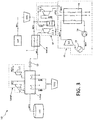
- FIG 1 shows a preferred embodiment of the power generation plant (10) of the invention
- the main source of energy of the power generation plant is a concentrated solar power system (CSP) of the central tower receiver type, working with air as heat transfer fluid or first working fluid (WF1).
- the nominal solar receiver outlet temperature is about 800 °C, but depending on the solar concentrating and receiver technology, it is possible to have higher or lower nominal temperatures.
- the solar receiver is of open volumetric type and comprises a ceramic or metallic absorber matrix.
- the solar receiver could either be of fixed matrix type, or active/moving matrix type (e.g. a rotary disc receiver).
- the fluid communication between the concentrated solar power system (CSP) and the first thermal energy storage system (TES1) is implemented for example by means of insulated ducts.
- the hot air (WF1) is released at a controlled rate from the first thermal energy storage system (TES1) and led to the high temperature heat exchanger (H-HEX), where the hot air (WF1) will transfer the heat to the second working fluid (WF2), the compressed air, prior to the intake of compressed air (WF2) in the gas turbine subsystem (GT).
- TES1 first thermal energy storage system
- H-HEX high temperature heat exchanger
- the second working fluid (WF2) is compressed by means of a compressor system (COMP), and stored at the compressed air storage (CAS).
- the compressor system (COMP) in this embodiment is a four-stage compression train (simplified in the figures as a two-stage (11.1, 11.2) compressor train), with three intercoolers and an aftercooler, implemented by the low temperature heat exchanger (L-HEX).
- L-HEX low temperature heat exchanger
- the thermal energy recovered by the intercoolers and aftercooler by means of the third working fluid (WF3) is stored in a low-temperature packed-bed thermocline, the second thermal energy storage (TES2).
- the heat generated during compression is then reused for preheating the compressed air (WF2) released from the compressed air storage (CAS) before throttling the compressed air (WF2) to the inlet pressure of the gas turbine subsystem (GT).
- WF2 compressed air
- CAS compressed air storage
- GT gas turbine subsystem
- the low temperature heat exchanger (L-HEX) is configured such that the intercoolers and aftercoolers can be also used as heaters before the expansion process.
- the layout of this heat exchanger (L-HEX) is of shell-and-tube type, where the third working fluid (WF3), in this embodiment atmospheric air, for cooling or heating, flows on the shell side and the compressed air flows on the tube side; in a preferred embodiment the third working fluid (WF3) circuitry of the low temperature heat exchanger (L-HEX), is configured to switch between a parallel flow for air cooling during compression and serial flow for air heating during the release of the compressed air (WF2).
- Electricity production is achieved by means of a combined cycle power generation system comprising a topping Brayton cycle gas turbine subsystem (GT) and a bottoming Rankine cycle steam turbine subsystem (ST).
- GT topping Brayton cycle gas turbine subsystem
- ST bottoming Rankine cycle steam turbine subsystem
- the topping gas turbine subsystem comprises a gas turbine (12) fed with the compressed air (WF2) heated in the high temperature heat exchanger (H-HEX) and expanded therein, such that the turbine (12) is coupled with a turbo-generator (17).
- the second working fluid (WF2) is at a relatively low pressure, but it still retains energy in the form of heat; this energy is employed as the hot source for the bottoming steam turbine subsystem (ST).
- the outlet of the gas turbine subsystem (GT) is in fluid communication with the boiler (B) of the steam turbine subsystem (ST), where the heat is transferred to a fourth working fluid (WF4) with phase change behavior in the range of working temperatures.
- this fourth working fluid (WF4) is water, i.e. steam, while in another embodiment is an organic compound and the steam turbine subsystem (ST) is an ORC, organic Rankine cycle subsystem.
- the fourth working fluid (WF4) is expanded in a steam turbine (14), and then condensed (15) and compressed (16) again before re-entering the boiler (B); the steam turbine (14) is coupled to a turbo-generator (18), such that its rotation generates electricity.
- Figure 2 shows an embodiment of the invention with a modified combined cycle
- the topping gas turbine subsystem comprises a compound gas turbine (12), with a high pressure part (12.1) and a low pressure part (12.2), or high and low pressure turbines (12.1, 12.2); thus, the high pressure turbine (12.1) receives compressed air (WF2) at high pressure, produces its expansion, and then conveys the partially expanded compressed air (WF2) to the re-heat heat exchanger, or re-heater (R-HEX).
- GT topping gas turbine subsystem
- the partially expanded compressed air (WF2) is heated with hot air (WF1) from the first heat storage (TES1), its enthalpy increased, and the compressed air (WF2) led to the inlet of the low pressure turbine (12.2).
- the expansion ratio of the high pressure turbine (12.1) is chosen such that the exit temperature of the high pressure turbine (12.1) is very similar to the exit temperature of low pressure turbine (12.2).
- FIG 3 shows an improvement of the previous embodiment, where the exhaust of the re-heater (R-HEX) is in fluid communication with the boiler (B) of the steam turbine subsystem (ST), where the remaining thermal energy of the hot air (WF1) is transferred to the fourth working fluid (WF4). If this residual heat of the hot air (WF1) was not used, the return air (WF1) would have to be wasted by rejection to the ambient.
- the positive effect of the reuse of the reheat air (WF1) return stream is that the power output and overall energy conversion ratio of the power plant (10) is increased. Also, the rated power output of the bottoming steam turbine subsystem (ST) is increased, in some cases roughly doubled, which increases the steam cycle efficiency.
- the compressed air storage is implemented in an embodiment by means of a geological formation, such as a natural cavern.
- a geological formation such as a natural cavern.
- an artificial pressure vessel such as a storage tank
- An improvement over the previous embodiment is represented by a pressure vessel immersed in a body of water. By immersing the pressure vessel, the surrounding pressure, dependent on the depth at which the vessel is immersed, balances the stresses produced by the pressure of the compressed air (WF2) against the walls of the vessel; thus, less resistant, and therefore not very costly materials can be used in the manufacturing of the pressure vessel.
- the high temperature heat exchanger (H-HEX) and/or the reheat heat exchanger (R-HEX) are either of conventional shell-and-tube type, or alternatively a fixed-bed regenerative systems, or regenerator.
- the fixed-bed regenerative system is charged under atmospheric pressure and discharged under pressurized conditions.
- the vessel size of this regenerative heat exchange system is limited due to the pressurization process, which requires several two-vessel subunits in parallel depending on the power rating.
- the second reason for arranging several two-vessel subunits in parallel is the requirement for a continuous thermal power transfer: while one system is pressurized or depressurized, the parallel systems need to take over.
- the power supply required to power the compressor system (COMP) comes conventionally from the grid, generated by unspecified sources; however, in order to enhance the sustainability of the power generation, environmentally friendly power sources for the compressor system (COMP) such as the following are preferred:
- thermocline thermal energy storage systems incorporate thermochemical energy storage technology or latent heat storage.
- the overall functionality as described above remains the same, but the energy storage density and/or the discharge/charge behavior (e.g. outlet temperature stabilization) of the thermal energy storage systems (TES1, TES2) could improve dramatically, reducing the size and costs of the thermal energy storage systems (TES1, TES2) for a given thermal storage capacity.
- the residual heat of the first and/or second working fluid can be used for applications where the temperature level is suitable; some examples of low temperature applications where the utilization of the heat might be possible are desalination, district or local heating, water heating, food production, etc.
Landscapes
- Engineering & Computer Science (AREA)
- Chemical & Material Sciences (AREA)
- Combustion & Propulsion (AREA)
- Mechanical Engineering (AREA)
- General Engineering & Computer Science (AREA)
- Life Sciences & Earth Sciences (AREA)
- Sustainable Development (AREA)
- Sustainable Energy (AREA)
- Physics & Mathematics (AREA)
- High Energy & Nuclear Physics (AREA)
- Engine Equipment That Uses Special Cycles (AREA)
Priority Applications (1)
| Application Number | Priority Date | Filing Date | Title |
|---|---|---|---|
| EP20382368.7A EP3907390A1 (de) | 2020-05-05 | 2020-05-05 | Stromerzeugungsanlage |
Applications Claiming Priority (1)
| Application Number | Priority Date | Filing Date | Title |
|---|---|---|---|
| EP20382368.7A EP3907390A1 (de) | 2020-05-05 | 2020-05-05 | Stromerzeugungsanlage |
Publications (1)
| Publication Number | Publication Date |
|---|---|
| EP3907390A1 true EP3907390A1 (de) | 2021-11-10 |
Family
ID=70779633
Family Applications (1)
| Application Number | Title | Priority Date | Filing Date |
|---|---|---|---|
| EP20382368.7A Withdrawn EP3907390A1 (de) | 2020-05-05 | 2020-05-05 | Stromerzeugungsanlage |
Country Status (1)
| Country | Link |
|---|---|
| EP (1) | EP3907390A1 (de) |
Cited By (5)
| Publication number | Priority date | Publication date | Assignee | Title |
|---|---|---|---|---|
| CN114592935A (zh) * | 2022-03-30 | 2022-06-07 | 西安热工研究院有限公司 | 一种燃气轮机-双压Kalina联合循环发电系统及方法 |
| CN114704380A (zh) * | 2022-03-14 | 2022-07-05 | 国网浙江省电力有限公司电力科学研究院 | 耦合热化学储能的燃煤机组调峰发电系统及方法 |
| CN114810243A (zh) * | 2022-05-27 | 2022-07-29 | 华能国际电力股份有限公司 | 一种锅炉烟气耦合压缩空气储能的燃煤发电系统及运行方法 |
| CN117266944A (zh) * | 2023-11-22 | 2023-12-22 | 泉州装备制造研究所 | 一种基于储气罐温度控制的绝热压缩空气储能系统 |
| CN114592935B (zh) * | 2022-03-30 | 2024-05-14 | 西安热工研究院有限公司 | 一种燃气轮机-双压Kalina联合循环发电系统及方法 |
Citations (3)
| Publication number | Priority date | Publication date | Assignee | Title |
|---|---|---|---|---|
| WO2011053411A1 (en) * | 2009-10-30 | 2011-05-05 | General Electric Company | Adiabatic compressed air energy storage system with liquid thermal energy storage |
| US20160047361A1 (en) * | 2014-08-15 | 2016-02-18 | King Fahd University Of Petroleum And Minerals | System and method using solar thermal energy for power, cogeneration and/or poly-generation using supercritical brayton cycles |
| WO2016079485A1 (en) * | 2014-11-17 | 2016-05-26 | Demetair Systems Ltd | A waste heat recovery system combined with compressed air energy storage |
-
2020
- 2020-05-05 EP EP20382368.7A patent/EP3907390A1/de not_active Withdrawn
Patent Citations (3)
| Publication number | Priority date | Publication date | Assignee | Title |
|---|---|---|---|---|
| WO2011053411A1 (en) * | 2009-10-30 | 2011-05-05 | General Electric Company | Adiabatic compressed air energy storage system with liquid thermal energy storage |
| US20160047361A1 (en) * | 2014-08-15 | 2016-02-18 | King Fahd University Of Petroleum And Minerals | System and method using solar thermal energy for power, cogeneration and/or poly-generation using supercritical brayton cycles |
| WO2016079485A1 (en) * | 2014-11-17 | 2016-05-26 | Demetair Systems Ltd | A waste heat recovery system combined with compressed air energy storage |
Non-Patent Citations (2)
| Title |
|---|
| BARD SVE WALLENTINSEN ET AL: "Concentrated Solar Power Gas Turbine Hybrid with Thermal Storage", 1 August 2016 (2016-08-01), XP055739374, Retrieved from the Internet <URL:https://ntnuopen.ntnu.no/ntnu-xmlui/bitstream/handle/11250/2402290/14810_FULLTEXT.pdf?sequence=1> [retrieved on 20201013] * |
| JAVIER GARCÍA-BARBERENA ET AL: "Advanced power cycles and configurations for solar towers: Modeling and optimization of the decoupled solar combined cycle concept", AIP CONFERENCE PROCEEDINGS, vol. 1850, 1 January 2017 (2017-01-01), NEW YORK, US, pages 060002, XP055739369, ISSN: 0094-243X, DOI: 10.1063/1.4984410 * |
Cited By (8)
| Publication number | Priority date | Publication date | Assignee | Title |
|---|---|---|---|---|
| CN114704380A (zh) * | 2022-03-14 | 2022-07-05 | 国网浙江省电力有限公司电力科学研究院 | 耦合热化学储能的燃煤机组调峰发电系统及方法 |
| CN114704380B (zh) * | 2022-03-14 | 2023-07-14 | 国网浙江省电力有限公司电力科学研究院 | 耦合热化学储能的燃煤机组调峰发电系统及方法 |
| CN114592935A (zh) * | 2022-03-30 | 2022-06-07 | 西安热工研究院有限公司 | 一种燃气轮机-双压Kalina联合循环发电系统及方法 |
| CN114592935B (zh) * | 2022-03-30 | 2024-05-14 | 西安热工研究院有限公司 | 一种燃气轮机-双压Kalina联合循环发电系统及方法 |
| CN114810243A (zh) * | 2022-05-27 | 2022-07-29 | 华能国际电力股份有限公司 | 一种锅炉烟气耦合压缩空气储能的燃煤发电系统及运行方法 |
| CN114810243B (zh) * | 2022-05-27 | 2023-05-26 | 华能国际电力股份有限公司 | 一种锅炉烟气耦合压缩空气储能的燃煤发电系统及运行方法 |
| CN117266944A (zh) * | 2023-11-22 | 2023-12-22 | 泉州装备制造研究所 | 一种基于储气罐温度控制的绝热压缩空气储能系统 |
| CN117266944B (zh) * | 2023-11-22 | 2024-02-13 | 泉州装备制造研究所 | 一种基于储气罐温度控制的绝热压缩空气储能系统 |
Similar Documents
| Publication | Publication Date | Title |
|---|---|---|
| US9541070B2 (en) | Plant for energy production | |
| US20120216536A1 (en) | Supercritical carbon dioxide power cycle configuration for use in concentrating solar power systems | |
| EP3907390A1 (de) | Stromerzeugungsanlage | |
| US8739512B2 (en) | Combined cycle power plant | |
| US20140366536A1 (en) | High temperature thermal energy for grid storage and concentrated solar plant enhancement | |
| US20080022683A1 (en) | Storing Thermal Energy and Generating Electricity | |
| EP3927949B1 (de) | Energiespeicheranlage und verfahren | |
| WO2016165932A1 (en) | Energy storage system and method | |
| CN116031913A (zh) | 一种基于卡诺电池储能技术的风电消纳储能系统 | |
| Sun | Hybrid solar power system | |
| US11591957B2 (en) | Energy storage apparatus and method | |
| Green et al. | Nuclear hybrid energy system: Molten salt energy storage | |
| Zaversky et al. | A novel high-efficiency solar thermal power plant featuring electricity storage-Ideal for the future power grid with high shares of renewables | |
| CN206694190U (zh) | 一种风光储能系统 | |
| WO2015077235A1 (en) | Concentrated solar power systems and methods utilizing cold thermal energy storage | |
| EP4118305A1 (de) | System und verfahren zur erzeugung erneuerbarer energie | |
| CN106677988A (zh) | 一种风光储能系统 | |
| US4285203A (en) | Means and method for simultaneously increasing the delivered peak power and reducing the rate of peak heat rejection of a power plant | |
| US20230163622A1 (en) | Hybrid energy storage systems | |
| CN115749998A (zh) | 烟气及新能源弃电耦合加热熔盐的装置系统及应用方法 | |
| Jílek et al. | Electricity storage systems using compressed air | |
| US9634169B1 (en) | Hybrid solar concentrator utilizing a dielectric spectrum splitter | |
| Fathi et al. | Nuclear systems for a low carbon electrical grid | |
| Ciocan et al. | HYBRID ENERGY STORAGE SYSTEMS FOR RENEWABLE ENERGY SOURCES: APPLICATIONS AND CHALLENGES. | |
| ZENARI | Simulation of a Gas Turbine-Organic Rankine Cycle Combined Power Plant with the integration of a direct Thermal Energy Storage to improve flexibility |
Legal Events
| Date | Code | Title | Description |
|---|---|---|---|
| PUAI | Public reference made under article 153(3) epc to a published international application that has entered the european phase |
Free format text: ORIGINAL CODE: 0009012 |
|
| STAA | Information on the status of an ep patent application or granted ep patent |
Free format text: STATUS: THE APPLICATION HAS BEEN PUBLISHED |
|
| STAA | Information on the status of an ep patent application or granted ep patent |
Free format text: STATUS: THE APPLICATION HAS BEEN WITHDRAWN |
|
| AK | Designated contracting states |
Kind code of ref document: A1 Designated state(s): AL AT BE BG CH CY CZ DE DK EE ES FI FR GB GR HR HU IE IS IT LI LT LU LV MC MK MT NL NO PL PT RO RS SE SI SK SM TR |
|
| B565 | Issuance of search results under rule 164(2) epc |
Effective date: 20201026 |
|
| 18W | Application withdrawn |
Effective date: 20211018 |