EP3907389B1 - Gas turbine compressor radial door bleed valve - Google Patents
Gas turbine compressor radial door bleed valve Download PDFInfo
- Publication number
- EP3907389B1 EP3907389B1 EP21172406.7A EP21172406A EP3907389B1 EP 3907389 B1 EP3907389 B1 EP 3907389B1 EP 21172406 A EP21172406 A EP 21172406A EP 3907389 B1 EP3907389 B1 EP 3907389B1
- Authority
- EP
- European Patent Office
- Prior art keywords
- bleed
- door
- doors
- duct
- circumferential end
- Prior art date
- Legal status (The legal status is an assumption and is not a legal conclusion. Google has not performed a legal analysis and makes no representation as to the accuracy of the status listed.)
- Active
Links
Images


Classifications
-
- F—MECHANICAL ENGINEERING; LIGHTING; HEATING; WEAPONS; BLASTING
- F02—COMBUSTION ENGINES; HOT-GAS OR COMBUSTION-PRODUCT ENGINE PLANTS
- F02C—GAS-TURBINE PLANTS; AIR INTAKES FOR JET-PROPULSION PLANTS; CONTROLLING FUEL SUPPLY IN AIR-BREATHING JET-PROPULSION PLANTS
- F02C6/00—Plural gas-turbine plants; Combinations of gas-turbine plants with other apparatus; Adaptations of gas-turbine plants for special use
- F02C6/04—Gas-turbine plants providing heated or pressurised working fluid for other apparatus, e.g. without mechanical power output
- F02C6/06—Gas-turbine plants providing heated or pressurised working fluid for other apparatus, e.g. without mechanical power output providing compressed gas
- F02C6/08—Gas-turbine plants providing heated or pressurised working fluid for other apparatus, e.g. without mechanical power output providing compressed gas the gas being bled from the gas-turbine compressor
-
- F—MECHANICAL ENGINEERING; LIGHTING; HEATING; WEAPONS; BLASTING
- F04—POSITIVE - DISPLACEMENT MACHINES FOR LIQUIDS; PUMPS FOR LIQUIDS OR ELASTIC FLUIDS
- F04D—NON-POSITIVE-DISPLACEMENT PUMPS
- F04D27/00—Control, e.g. regulation, of pumps, pumping installations or pumping systems specially adapted for elastic fluids
- F04D27/02—Surge control
- F04D27/0207—Surge control by bleeding, bypassing or recycling fluids
- F04D27/0215—Arrangements therefor, e.g. bleed or by-pass valves
-
- F—MECHANICAL ENGINEERING; LIGHTING; HEATING; WEAPONS; BLASTING
- F04—POSITIVE - DISPLACEMENT MACHINES FOR LIQUIDS; PUMPS FOR LIQUIDS OR ELASTIC FLUIDS
- F04D—NON-POSITIVE-DISPLACEMENT PUMPS
- F04D27/00—Control, e.g. regulation, of pumps, pumping installations or pumping systems specially adapted for elastic fluids
- F04D27/02—Surge control
- F04D27/0207—Surge control by bleeding, bypassing or recycling fluids
- F04D27/023—Details or means for fluid extraction
-
- F—MECHANICAL ENGINEERING; LIGHTING; HEATING; WEAPONS; BLASTING
- F02—COMBUSTION ENGINES; HOT-GAS OR COMBUSTION-PRODUCT ENGINE PLANTS
- F02K—JET-PROPULSION PLANTS
- F02K3/00—Plants including a gas turbine driving a compressor or a ducted fan
- F02K3/02—Plants including a gas turbine driving a compressor or a ducted fan in which part of the working fluid by-passes the turbine and combustion chamber
- F02K3/04—Plants including a gas turbine driving a compressor or a ducted fan in which part of the working fluid by-passes the turbine and combustion chamber the plant including ducted fans, i.e. fans with high volume, low pressure outputs, for augmenting the jet thrust, e.g. of double-flow type
- F02K3/075—Plants including a gas turbine driving a compressor or a ducted fan in which part of the working fluid by-passes the turbine and combustion chamber the plant including ducted fans, i.e. fans with high volume, low pressure outputs, for augmenting the jet thrust, e.g. of double-flow type controlling flow ratio between flows
-
- F—MECHANICAL ENGINEERING; LIGHTING; HEATING; WEAPONS; BLASTING
- F05—INDEXING SCHEMES RELATING TO ENGINES OR PUMPS IN VARIOUS SUBCLASSES OF CLASSES F01-F04
- F05D—INDEXING SCHEME FOR ASPECTS RELATING TO NON-POSITIVE-DISPLACEMENT MACHINES OR ENGINES, GAS-TURBINES OR JET-PROPULSION PLANTS
- F05D2220/00—Application
- F05D2220/30—Application in turbines
- F05D2220/32—Application in turbines in gas turbines
- F05D2220/323—Application in turbines in gas turbines for aircraft propulsion, e.g. jet engines
-
- F—MECHANICAL ENGINEERING; LIGHTING; HEATING; WEAPONS; BLASTING
- F05—INDEXING SCHEMES RELATING TO ENGINES OR PUMPS IN VARIOUS SUBCLASSES OF CLASSES F01-F04
- F05D—INDEXING SCHEME FOR ASPECTS RELATING TO NON-POSITIVE-DISPLACEMENT MACHINES OR ENGINES, GAS-TURBINES OR JET-PROPULSION PLANTS
- F05D2240/00—Components
- F05D2240/35—Combustors or associated equipment
-
- F—MECHANICAL ENGINEERING; LIGHTING; HEATING; WEAPONS; BLASTING
- F05—INDEXING SCHEMES RELATING TO ENGINES OR PUMPS IN VARIOUS SUBCLASSES OF CLASSES F01-F04
- F05D—INDEXING SCHEME FOR ASPECTS RELATING TO NON-POSITIVE-DISPLACEMENT MACHINES OR ENGINES, GAS-TURBINES OR JET-PROPULSION PLANTS
- F05D2240/00—Components
- F05D2240/55—Seals
-
- F—MECHANICAL ENGINEERING; LIGHTING; HEATING; WEAPONS; BLASTING
- F05—INDEXING SCHEMES RELATING TO ENGINES OR PUMPS IN VARIOUS SUBCLASSES OF CLASSES F01-F04
- F05D—INDEXING SCHEME FOR ASPECTS RELATING TO NON-POSITIVE-DISPLACEMENT MACHINES OR ENGINES, GAS-TURBINES OR JET-PROPULSION PLANTS
- F05D2250/00—Geometry
- F05D2250/40—Movement of components
- F05D2250/41—Movement of components with one degree of freedom
- F05D2250/411—Movement of components with one degree of freedom in rotation
-
- F—MECHANICAL ENGINEERING; LIGHTING; HEATING; WEAPONS; BLASTING
- F05—INDEXING SCHEMES RELATING TO ENGINES OR PUMPS IN VARIOUS SUBCLASSES OF CLASSES F01-F04
- F05D—INDEXING SCHEME FOR ASPECTS RELATING TO NON-POSITIVE-DISPLACEMENT MACHINES OR ENGINES, GAS-TURBINES OR JET-PROPULSION PLANTS
- F05D2260/00—Function
- F05D2260/50—Kinematic linkage, i.e. transmission of position
-
- F—MECHANICAL ENGINEERING; LIGHTING; HEATING; WEAPONS; BLASTING
- F05—INDEXING SCHEMES RELATING TO ENGINES OR PUMPS IN VARIOUS SUBCLASSES OF CLASSES F01-F04
- F05D—INDEXING SCHEME FOR ASPECTS RELATING TO NON-POSITIVE-DISPLACEMENT MACHINES OR ENGINES, GAS-TURBINES OR JET-PROPULSION PLANTS
- F05D2270/00—Control
- F05D2270/01—Purpose of the control system
- F05D2270/10—Purpose of the control system to cope with, or avoid, compressor flow instabilities
- F05D2270/101—Compressor surge or stall
Definitions
- Exemplary embodiments of the present invention pertain to the art of gas turbine engines, and in particular to bleed valve configurations of compressors of gas turbine engines.
- a gas turbine engine typically includes one or more bleed valves to bleed airflow from the compressor section.
- bleed valves may bleed airflow from the compressor section at a high pressure compressor or at a low pressure compressor of the gas turbine engine.
- the bleed valves are opened at operating conditions such as engine start to remove excess airflow from the core flowpath, and also opened during operation for, for example, engine surge avoidance.
- a bleed valve is a low pressure compressor exit bleed valve, which when open allows airflow to bleed from the low compressor section.
- the bleed valve is an annular ring covering a bleed duct, the bleed duct extending from the compressor flow path.
- the annular ring is moved axially and circumferentially. This axial motion of the valve requires additional axial space around the valve location to accommodate the axial travel of the valve.
- placement of flanges and/or other features of the compressor may be limited by the need for this additional axial space.
- US 5,048,286 discloses a bypass valve system wherein valve doors move in an axial and radial direction when actuated by circumferential travel of an actuation ring.
- a bleed system for a gas turbine engine includes a bleed duct having a duct inlet for locating at a flowpath of a gas turbine engine, and a duct outlet for locating outside of the flowpath, the bleed duct extending circumferentially around a central longitudinal axis.
- a plurality of bleed doors are located at the duct reed outlet and are arrayed along a circumferential length on the bleed duct.
- Each bleed door includes a first circumferential end, and a second circumferential end.
- the plurality of bleed doors are arrayed such that when the plurality of bleed doors are in a closed position the first circumferential end is located at the second circumferential end of an adjacent bleed door of the plurality of bleed doors.
- Each bleed door includes a pivot, such that each bleed door rotates about the pivot from the closed position covering the duct outlet to an opened position for allowing a bleed airflow to pass through the duct outlet.
- the bleed doors When the plurality of bleed doors are in the opened position, the bleed doors extend from their pivots in a circumferential swirl direction of the bleed airflow through the bleed duct.
- the bleed system includes a synchronization ring, and a linkage arm extending from the synchronization ring to a bleed door of the plurality of bleed doors such that circumferential movement of the synchronization ring about the central longitudinal axis urges rotation of the bleed door about the pivot between the closed position and the open position.
- the linkage arm is connected to the bleed door between the pivot and the first circumferential end of the bleed door.
- the pivot is located at or near the second circumferential end of the bleed door.
- each bleed door of the plurality of bleed doors circumferentially overlaps the second circumferential end of the adjacent bleed door of the plurality of bleed doors.
- each bleed door of the plurality of bleed doors includes a perimetrical seal to seal the bleed door to the duct outlet when the bleed door is in the closed position.
- each bleed door of the plurality of bleed doors includes an inner radial surface extending through the duct outlet into the bleed duct when the bleed door is in the closed position.
- the inner radial surface is profiled to allow for smooth egress of the bleed airflow from the duct outlet.
- a gas turbine engine includes a combustor, a turbine driven by combustion gases output from the combustor, and a compressor driven by the turbine, the compressor including the bleed system described above.
- the pivot is secured to a fixed structure of the gas turbine engine.
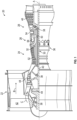
- FIG. 1 schematically illustrates a gas turbine engine 20.
- the gas turbine engine 20 is disclosed herein as a two-spool turbofan that generally incorporates a fan section 22, a compressor section 24, a combustor section 26 and a turbine section 28.
- Alternative engines might include other systems or features.
- the fan section 22 drives air along a bypass flow path B in a bypass duct, while the compressor section 24 drives air along a core flow path C for compression and communication into the combustor section 26 then expansion through the turbine section 28.
- FIG. 1 schematically illustrates a gas turbine engine 20.
- the gas turbine engine 20 is disclosed herein as a two-spool turbofan that generally incorporates a fan section 22, a compressor section 24, a combustor section 26 and a turbine section 28.
- Alternative engines might include other systems or features.
- the fan section 22 drives air along a bypass flow path B in a bypass duct
- the compressor section 24 drives air along a core flow path C for compression and communication into the combustor section 26
- the exemplary engine 20 generally includes a low speed spool 30 and a high speed spool 32 mounted for rotation about an engine central longitudinal axis A relative to an engine static structure 36 via several bearing systems 38. It should be understood that various bearing systems 38 at various locations may alternatively or additionally be provided, and the location of bearing systems 38 may be varied as appropriate to the application.
- the low speed spool 30 generally includes an inner shaft 40 that interconnects a fan 42, a low pressure compressor 44 and a low pressure turbine 46.
- the inner shaft 40 is connected to the fan 42 through a speed change mechanism, which in exemplary gas turbine engine 20 is illustrated as a geared architecture 48 to drive the fan 42 at a lower speed than the low speed spool 30.
- the high speed spool 32 includes an outer shaft 50 that interconnects a high pressure compressor 52 and high pressure turbine 54.
- a combustor 56 is arranged in exemplary gas turbine 20 between the high pressure compressor 52 and the high pressure turbine 54.
- An engine static structure 36 is arranged generally between the high pressure turbine 54 and the low pressure turbine 46.
- the engine static structure 36 further supports bearing systems 38 in the turbine section 28.
- the inner shaft 40 and the outer shaft 50 are concentric and rotate via bearing systems 38 about the engine central longitudinal axis A which is collinear with their longitudinal axes.
- each of the positions of the fan section 22, compressor section 24, combustor section 26, turbine section 28, and fan drive gear system 48 may be varied.
- gear system 48 may be located aft of combustor section 26 or even aft of turbine section 28, and fan section 22 may be positioned forward or aft of the location of gear system 48.
- the engine 20 in one example is a high-bypass geared aircraft engine.
- the engine 20 bypass ratio is greater than about six (6), with an example embodiment being greater than about ten (10)
- the geared architecture 48 is an epicyclic gear train, such as a planetary gear system or other gear system, with a gear reduction ratio of greater than about 2.3
- the low pressure turbine 46 has a pressure ratio that is greater than about five.
- the engine 20 bypass ratio is greater than about ten (10:1)
- the fan diameter is significantly larger than that of the low pressure compressor 44
- the low pressure turbine 46 has a pressure ratio that is greater than about five 5: 1.
- the fan section 22 of the engine 20 is designed for a particular flight condition--typically cruise at about 0.8Mach and about 35,000 feet (10,688 meters).
- 'TSFC' Thrust Specific Fuel Consumption
- Low fan pressure ratio is the pressure ratio across the fan blade alone, without a Fan Exit Guide Vane (“FEGV”) system.
Landscapes
- Engineering & Computer Science (AREA)
- Mechanical Engineering (AREA)
- General Engineering & Computer Science (AREA)
- Life Sciences & Earth Sciences (AREA)
- Sustainable Development (AREA)
- Chemical & Material Sciences (AREA)
- Combustion & Propulsion (AREA)
- Structures Of Non-Positive Displacement Pumps (AREA)
Description
- Exemplary embodiments of the present invention pertain to the art of gas turbine engines, and in particular to bleed valve configurations of compressors of gas turbine engines.
- A gas turbine engine typically includes one or more bleed valves to bleed airflow from the compressor section. For example, such bleed valves may bleed airflow from the compressor section at a high pressure compressor or at a low pressure compressor of the gas turbine engine. The bleed valves are opened at operating conditions such as engine start to remove excess airflow from the core flowpath, and also opened during operation for, for example, engine surge avoidance.
- One example of such a bleed valve is a low pressure compressor exit bleed valve, which when open allows airflow to bleed from the low compressor section. The bleed valve is an annular ring covering a bleed duct, the bleed duct extending from the compressor flow path. To open or close the bleed valve, the annular ring is moved axially and circumferentially. This axial motion of the valve requires additional axial space around the valve location to accommodate the axial travel of the valve. Thus, placement of flanges and/or other features of the compressor may be limited by the need for this additional axial space.
-
US 5,048,286 discloses a bypass valve system wherein valve doors move in an axial and radial direction when actuated by circumferential travel of an actuation ring. - According to a first aspect, a bleed system for a gas turbine engine includes a bleed duct having a duct inlet for locating at a flowpath of a gas turbine engine, and a duct outlet for locating outside of the flowpath, the bleed duct extending circumferentially around a central longitudinal axis. A plurality of bleed doors are located at the duct reed outlet and are arrayed along a circumferential length on the bleed duct. Each bleed door includes a first circumferential end, and a second circumferential end. The plurality of bleed doors are arrayed such that when the plurality of bleed doors are in a closed position the first circumferential end is located at the second circumferential end of an adjacent bleed door of the plurality of bleed doors. Each bleed door includes a pivot, such that each bleed door rotates about the pivot from the closed position covering the duct outlet to an opened position for allowing a bleed airflow to pass through the duct outlet. When the plurality of bleed doors are in the opened position, the bleed doors extend from their pivots in a circumferential swirl direction of the bleed airflow through the bleed duct.
- Optionally, the bleed system includes a synchronization ring, and a linkage arm extending from the synchronization ring to a bleed door of the plurality of bleed doors such that circumferential movement of the synchronization ring about the central longitudinal axis urges rotation of the bleed door about the pivot between the closed position and the open position.
- Optionally, the linkage arm is connected to the bleed door between the pivot and the first circumferential end of the bleed door.
- Optionally, the pivot is located at or near the second circumferential end of the bleed door.
- Optionally, the first circumferential end of each bleed door of the plurality of bleed doors circumferentially overlaps the second circumferential end of the adjacent bleed door of the plurality of bleed doors.
- Optionally, each bleed door of the plurality of bleed doors includes a perimetrical seal to seal the bleed door to the duct outlet when the bleed door is in the closed position.
- Optionally, each bleed door of the plurality of bleed doors includes an inner radial surface extending through the duct outlet into the bleed duct when the bleed door is in the closed position.
- Optionally, the inner radial surface is profiled to allow for smooth egress of the bleed airflow from the duct outlet.
- According to another aspect, a gas turbine engine includes a combustor, a turbine driven by combustion gases output from the combustor, and a compressor driven by the turbine, the compressor including the bleed system described above.
- Optionally, the pivot is secured to a fixed structure of the gas turbine engine.
- The following descriptions of exemplary embodiments are by way of example only and should not be considered limiting in any way. With reference to the accompanying drawings, like elements are numbered alike:
-
FIG. 1 is a partial cross-sectional view of a gas turbine engine; -
FIG. 2 is a partial cross-sectional view of a compressor section of a gas turbine engine; -
FIG. 3 is a partial cross-sectional view of a bleed door system in a closed position; -
FIG. 4 is a partial cross-sectional view of a bleed door system in an opened position; -
FIG. 5 is a partial perspective view of a bleed door system in an opened position; -
FIG. 6 is a partial cross-sectional view of a bleed door system in a closed position; -
FIG. 7 is a partial cross-sectional view of a bleed door system in an opened position. - A detailed description of one or more embodiments of the disclosed apparatus and method are presented herein by way of exemplification and not limitation with reference to the Figures.
-
FIG. 1 schematically illustrates agas turbine engine 20. Thegas turbine engine 20 is disclosed herein as a two-spool turbofan that generally incorporates afan section 22, acompressor section 24, acombustor section 26 and aturbine section 28. Alternative engines might include other systems or features. Thefan section 22 drives air along a bypass flow path B in a bypass duct, while thecompressor section 24 drives air along a core flow path C for compression and communication into thecombustor section 26 then expansion through theturbine section 28. Although depicted as a two-spool turbofan gas turbine engine in the disclosed non-limiting embodiment, it should be understood that the concepts described herein are not limited to use with two-spool turbofans as the teachings may be applied to other types of turbine engines including three-spool architectures. - The
exemplary engine 20 generally includes alow speed spool 30 and ahigh speed spool 32 mounted for rotation about an engine central longitudinal axis A relative to an enginestatic structure 36 viaseveral bearing systems 38. It should be understood thatvarious bearing systems 38 at various locations may alternatively or additionally be provided, and the location ofbearing systems 38 may be varied as appropriate to the application. - The
low speed spool 30 generally includes aninner shaft 40 that interconnects afan 42, alow pressure compressor 44 and alow pressure turbine 46. Theinner shaft 40 is connected to thefan 42 through a speed change mechanism, which in exemplarygas turbine engine 20 is illustrated as a gearedarchitecture 48 to drive thefan 42 at a lower speed than thelow speed spool 30. Thehigh speed spool 32 includes anouter shaft 50 that interconnects ahigh pressure compressor 52 andhigh pressure turbine 54. Acombustor 56 is arranged inexemplary gas turbine 20 between thehigh pressure compressor 52 and thehigh pressure turbine 54. An enginestatic structure 36 is arranged generally between thehigh pressure turbine 54 and thelow pressure turbine 46. The enginestatic structure 36 further supports bearingsystems 38 in theturbine section 28. Theinner shaft 40 and theouter shaft 50 are concentric and rotate viabearing systems 38 about the engine central longitudinal axis A which is collinear with their longitudinal axes. - The core airflow is compressed by the
low pressure compressor 44 then thehigh pressure compressor 52, mixed and burned with fuel in thecombustor 56, then expanded over thehigh pressure turbine 54 andlow pressure turbine 46. Theturbines low speed spool 30 andhigh speed spool 32 in response to the expansion. It will be appreciated that each of the positions of thefan section 22,compressor section 24,combustor section 26,turbine section 28, and fandrive gear system 48 may be varied. For example,gear system 48 may be located aft ofcombustor section 26 or even aft ofturbine section 28, andfan section 22 may be positioned forward or aft of the location ofgear system 48. - The
engine 20 in one example is a high-bypass geared aircraft engine. In a further example, theengine 20 bypass ratio is greater than about six (6), with an example embodiment being greater than about ten (10), the gearedarchitecture 48 is an epicyclic gear train, such as a planetary gear system or other gear system, with a gear reduction ratio of greater than about 2.3 and thelow pressure turbine 46 has a pressure ratio that is greater than about five. In one disclosed embodiment, theengine 20 bypass ratio is greater than about ten (10:1), the fan diameter is significantly larger than that of thelow pressure compressor 44, and thelow pressure turbine 46 has a pressure ratio that is greater than about five 5: 1.Low pressure turbine 46 pressure ratio is pressure measured prior to inlet oflow pressure turbine 46 as related to the pressure at the outlet of thelow pressure turbine 46 prior to an exhaust nozzle. The gearedarchitecture 48 may be an epicycle gear train, such as a planetary gear system or other gear system, with a gear reduction ratio of greater than about 2.3:1. It should be understood, however, that the above parameters are only exemplary of one embodiment of a geared architecture engine and that the present disclosure is applicable to other gas turbine engines including direct drive turbofans. - A significant amount of thrust is provided by the bypass flow B due to the high bypass ratio. The
fan section 22 of theengine 20 is designed for a particular flight condition--typically cruise at about 0.8Mach and about 35,000 feet (10,688 meters). The flight condition of 0.8 Mach and 35,000 ft (10,688 meters), with the engine at its best fuel consumption--also known as "bucket cruise Thrust Specific Fuel Consumption ('TSFC')"--is the industry standard parameter of lbm of fuel being burned divided by lbf of thrust the engine produces at that minimum point. "Low fan pressure ratio" is the pressure ratio across the fan blade alone, without a Fan Exit Guide Vane ("FEGV") system. The low fan pressure ratio as disclosed herein according to one non-limiting embodiment is less than about 1.45. "Low corrected fan tip speed" is the actual fan tip speed in ft/sec divided by an industry standard temperature correction of [(Tram °R)/(518.7 °R)]0.5. The "Low corrected fan tip speed" as disclosed herein according to one non-limiting embodiment is less than about 1150 ft/second (350.5 m/sec). - Referring now to
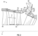
FIG. 2 , illustrated is a partial cross-section of thelow pressure compressor 44. The low pressure compressor includes one or morelow compressor rotors 60 disposed in acompressor case 62 or other static structure. Aninner wall 64 of thecompressor case 62 at least partially defines core flowpath C through thelow pressure compressor 44. Thelow pressure compressor 44 further includes one ormore bleed ducts 66 extending outwardly from the core flowpath C to selectablydirect bleed airflow 68 from the core flowpath C to a location outside of thelow pressure compressor 44, such as to theturbine section 28 to be utilized for component cooling, or overboard. Thebleed duct 66 extends from aduct inlet 70 at the core flowpath C to aduct outlet 72 radially outboard of the core flowpath C. Further, thebleed duct 66 has anupstream duct wall 74 defining an upstream extent of thebleed duct 66 relative to the engine central longitudinal axis A, and adownstream duct wall 76 opposite theupstream duct wall 74 thereby defining anaxial width 78 of thebleed duct 66. Theupstream duct wall 74 and thedownstream duct wall 76 extend circumferentially about the engine longitudinal axis A. In some embodiments, one or more duct struts 80 extend from theupstream duct wall 74 to thedownstream duct wall 76 to provide structural support to thebleed duct 66, and divide thebleed duct 66 into a plurality of circumferentialbleed duct segments 82, as best shown inFIG. 3 . - Referring now to
FIG. 3 ,4 and5 , illustrated is an embodiment of ableed door system 84. Thebleed door system 84 includes a plurality ofbleed doors 86 arrayed circumferentially about thebleed duct 66. In some embodiments, each bleeddoor 86 of the plurality of bleed doors is located at a correspondingbleed duct segment 82 of the plurality ofbleed duct segments 82. The plurality ofbleed doors 86 are located at theduct outlet 72, closing theduct outlet 72 when thebleed doors 86 are in a closed position as inFIG. 3 , and allowingbleed airflow 68 to pass through theduct outlet 72 when thebleed doors 86 are in an open position as shown inFIG. 4 . - Each
bleed door 86 has aninner door surface 88 closed to theduct outlet 72 and anouter door surface 90 opposite theinner door surface 88. Thebleed door 86 includes a firstcircumferential end 92 and a secondcircumferential end 94 opposite the firstcircumferential end 92. Thebleed doors 86 are circumferentially arrayed such that a firstcircumferential end 92 of ableed door 86 abuts a secondcircumferential end 94 of anadjacent bleed door 86. In some embodiments, the firstcircumferential end 92 includes alip 96, which overlaps the secondcircumferential end 94 of theadjacent bleed door 86, as shown inFIG. 3 . In some embodiments, a seal (not shown) extends around a perimeter of thebleed door 86 to improve sealing to theduct outlet 72 when thebleed doors 86 are in the closed position. While in some embodiments, thebleed door 86 seals to theduct outlet 72, in other embodiments theadjacent bleed doors 86 may seal to each other in addition to or as an alternative to sealing to theduct outlet 72. - The
bleed door system 84 further includes asynchronization ring 100 that is driven circumferentially about the engine central longitudinal axis A, by an actuator (not shown). Thesynchronization ring 100 is operably connected to each of thebleed doors 86 such that the circumferential movement of thesynchronization ring 100 moves thebleed doors 86 between the closed position and open position as shown inFIGs. 3 and4 . - The
synchronization ring 100 is connected to thebleed doors 86 by alinkage arm 102 extending between thesynchronization ring 100 and thebleed doors 86. Thebleed doors 86 each include apivot 104 at which thebleed door 86 is rotationally connected to a static structure, such ascase 106. In some embodiments thepivot 104 is located at or near the secondcircumferential end 94. Thelinkage arm 102 connects to thebleed door 86 between thepivot 104 and the firstcircumferential end 92. In some embodiments, thebleed door 86 includes ribs orprotrusions 108 extending from theouter door surface 90 to accommodate thepivot 104 and attachment of thelinkage arm 102. As shown inFIG. 4 , circumferential rotation of thesynchronization ring 100 urges thebleed doors 86 to each rotate radially outwardly about theirrespective pivot 104 and move from the closed position to the open position, thereby allowing thebleed airflow 68 therethrough. - As shown in
FIG. 4 , thebleed airflow 68 in thebleed duct 66 has a circumferential component, or swirl. Thebleed doors 86 are oriented such that when in the opened position, thebleed doors 86 extend from thepivot 104 in the swirl direction. This orientation reduces flow losses when thebleed doors 86 are open. Further, referring again toFIG. 3 , when thebleed doors 86 are closed, thesynchronization ring 100 is aligned so that maximum mechanical advantage from the corresponding position of thelinkage arms 102 is applied to thebleed doors 86 during high load conditions, thus maintaining closure of thebleed doors 86. Conversely, motion of thelinkage arms 102 increases in the opening direction when air is required to be dumped quickly. - In some embodiments, such as shown in
FIGs. 6 and7 , theinner door surface 88 extends at least partially into thebleed duct 66, reducing an effective length of thebleed duct 66 from theduct inlet 70 to theinner door surface 88. This reduction in effective length increases an effective acoustic frequency of thebleed duct 66 consistent with the length reduction when thebleed door 86 is in the closed position, as shown inFIG. 6 . Further, theinner door surface 88 may be contoured or profiled to allow smooth egress of thebleed airflow 68 when thebleed door 86 is in the open position, as shown inFIG. 7 . - The
bleed door system 84 configurations illustrated and described herein require less axial space than the typical axially-opening bleed valve configuration and reduces or removes axial design constraints due to the bleed valve. Further, thebleed doors 86 may be configured to extend radially into thebleed duct 66 to provide frequency tuning solutions to address flowpath resonance issues. - The term "about" is intended to include the degree of error associated with measurement of the particular quantity based upon the equipment available at the time of filing the application. For example, "about" can include a range of ± 8% or 5%, or 2% of a given value.
- The terminology used herein is for the purpose of describing particular embodiments only and is not intended to be limiting of the present disclosure. As used herein, the singular forms "a", "an" and "the" are intended to include the plural forms as well, unless the context clearly indicates otherwise. It will be further understood that the terms "comprises" and/or "comprising," when used in this specification, specify the presence of stated features, integers, steps, operations, elements, and/or components, but do not preclude the presence or addition of one or more other features, integers, steps, operations, element components, and/or groups thereof.
- While the present disclosure has been described with reference to an exemplary embodiment or embodiments, it will be understood by those skilled in the art that various changes may be made without departing from the scope of the present invention as defined by the claims. In addition, many modifications may be made to adapt a particular situation or material to the teachings of the present disclosure without departing from the scope of the claims. Therefore, it is intended that the present invention not be limited to the particular embodiment disclosed as the best mode contemplated for carrying out this present disclosure, but that the present invention will include all embodiments falling within the scope of the claims.
Claims (10)
- A bleed system for a gas turbine engine (20), comprising:a bleed duct (66) having a duct inlet (70) for locating at a flowpath of a gas turbine engine, and a duct outlet (72) for locating outside of the flowpath, the bleed duct extending circumferentially around a central longitudinal axis;a plurality of bleed doors (86) located at the duct outlet and arrayed along a circumferential length on the bleed duct, each bleed door including:a first circumferential end (92);a second circumferential end (94), the plurality of bleed doors arrayed such that when the plurality of bleed doors are in a closed position the first circumferential end is located at the second circumferential end of an adjacent bleed door of the plurality of bleed doors; anda pivot (104), such that each bleed door rotates about the pivot from the closed position covering the duct outlet (72) to an opened position for allowing a bleed airflow (68) to pass through the duct outlet;characterized in that, when the plurality of bleed doors (86) are in the opened position, the bleed doors extend from their pivots (104) in a circumferential swirl direction of the bleed airflow (68) through the bleed duct (66).
- The bleed system of claim 1, further comprising:a synchronization ring (100); anda linkage arm (102) extending from the synchronization ring to a bleed door (86) of the plurality of bleed doors such that circumferential movement of the synchronization ring about the central longitudinal axis urges rotation of the bleed door about the pivot (104) between the closed position and the open position.
- The bleed system of claim 2, wherein the linkage arm (102) is connected to the bleed door (86) between the pivot (104) and the first circumferential end (92) of the bleed door.
- The bleed system of any preceding claim, wherein the pivot (104) is located at or near the second circumferential end (94) of the bleed door (86).
- The bleed system of any preceding claim, wherein the first circumferential end (92) of each bleed door (86) of the plurality of bleed doors circumferentially overlaps the second circumferential end (94) of the adjacent bleed door of the plurality of bleed doors.
- The bleed system of any preceding claim, wherein each bleed door (86) of the plurality of bleed doors includes a perimetrical seal to seal the bleed door to the duct outlet (72) when the bleed door is in the closed position.
- The bleed system of any preceding claim, wherein each bleed door (86) of the plurality of bleed doors includes an inner radial surface (88) extending through the duct outlet (72) into the bleed duct (66) when the bleed door is in the closed position.
- The bleed system of claim 7, wherein the inner radial surface (88) is profiled to allow for smooth egress of the bleed airflow (68) from the duct outlet (72).
- A gas turbine engine (20), comprising:a combustor (56);a turbine (46, 54) driven by combustion gases output from the combustor; anda compressor (44, 52) driven by the turbine, the compressor including the bleed system of any preceding claim.
- The gas turbine engine (20) of claim 9, wherein the pivot (104) is secured to a fixed structure of the gas turbine engine (20).
Applications Claiming Priority (1)
| Application Number | Priority Date | Filing Date | Title |
|---|---|---|---|
| US16/869,847 US11428234B2 (en) | 2020-05-08 | 2020-05-08 | Gas turbine compressor radial door bleed valve |
Publications (2)
| Publication Number | Publication Date |
|---|---|
| EP3907389A1 EP3907389A1 (en) | 2021-11-10 |
| EP3907389B1 true EP3907389B1 (en) | 2025-06-25 |
Family
ID=75825623
Family Applications (1)
| Application Number | Title | Priority Date | Filing Date |
|---|---|---|---|
| EP21172406.7A Active EP3907389B1 (en) | 2020-05-08 | 2021-05-06 | Gas turbine compressor radial door bleed valve |
Country Status (2)
| Country | Link |
|---|---|
| US (1) | US11428234B2 (en) |
| EP (1) | EP3907389B1 (en) |
Family Cites Families (8)
| Publication number | Priority date | Publication date | Assignee | Title |
|---|---|---|---|---|
| DE1114980B (en) * | 1959-10-02 | 1961-10-12 | Entwicklungsbau Pirna Veb | Air blow-off device on axial compressors of gas turbines |
| US5048286A (en) * | 1990-06-29 | 1991-09-17 | General Electric Company | Bypass valve door |
| US5054286A (en) | 1990-06-29 | 1991-10-08 | General Electric Company | Bypass valve system |
| US6048171A (en) | 1997-09-09 | 2000-04-11 | United Technologies Corporation | Bleed valve system |
| GB2443982B (en) | 2006-01-20 | 2011-06-22 | Rolls Royce Power Eng | Bleed off valve system |
| DE102013215371A1 (en) * | 2013-08-05 | 2015-02-05 | Rolls-Royce Deutschland Ltd & Co Kg | Apparatus and method for blowing off compressor air in an engine |
| US10287992B2 (en) | 2015-08-26 | 2019-05-14 | General Electric Company | Gas turbine engine hybrid variable bleed valve |
| US10830179B2 (en) | 2017-03-01 | 2020-11-10 | General Electric Company | Variable bleed valve door assembly and system for gas turbine engines |
-
2020
- 2020-05-08 US US16/869,847 patent/US11428234B2/en active Active
-
2021
- 2021-05-06 EP EP21172406.7A patent/EP3907389B1/en active Active
Also Published As
| Publication number | Publication date |
|---|---|
| US20210348618A1 (en) | 2021-11-11 |
| EP3907389A1 (en) | 2021-11-10 |
| US11428234B2 (en) | 2022-08-30 |
Similar Documents
| Publication | Publication Date | Title |
|---|---|---|
| US11092030B2 (en) | Adaptive case for a gas turbine engine | |
| EP3536912B1 (en) | Profiled bellcrank vane actuation system | |
| EP3760838B1 (en) | Gas turbine variable vane system and method | |
| EP3869024B1 (en) | High bypass ratio engine bypass duct nozzle with controlled nozzle area | |
| EP3748147B1 (en) | Gas turbine engine bleed valve damping guide link | |
| EP3772570A1 (en) | Hydrostatic seal with extended carrier arm | |
| EP3907389B1 (en) | Gas turbine compressor radial door bleed valve | |
| EP3623587B1 (en) | Airfoil assembly for a gas turbine engine | |
| EP3470656B1 (en) | Modulated combustor bypass | |
| EP3502455B1 (en) | Bleed valve system | |
| EP3611358B1 (en) | Bleed valve actuation system | |
| US11181004B2 (en) | Confinement of a rope seal about a passage using a backing plate | |
| EP3508790B1 (en) | Gas turbine engine with modulated combustor bypass and combustor bypass valve | |
| EP4556684A1 (en) | Slider seal for gas turbine engine | |
| EP4372208A1 (en) | Seal for gas turbine engine | |
| US20200141264A1 (en) | Gas turbine engine structure with integrated actuation features | |
| EP3715641B1 (en) | Notched axial flange for a split case compressor | |
| EP3460226B1 (en) | Moveable exhaust plug liner | |
| EP3495621B1 (en) | Support ring for a gas turbine engine | |
| EP3550113A2 (en) | Gas turbine engine having cantilevered stators with sealing members | |
| EP3428404A1 (en) | Stator vane assembly for a gas turbine engine |
Legal Events
| Date | Code | Title | Description |
|---|---|---|---|
| PUAI | Public reference made under article 153(3) epc to a published international application that has entered the european phase |
Free format text: ORIGINAL CODE: 0009012 |
|
| STAA | Information on the status of an ep patent application or granted ep patent |
Free format text: STATUS: THE APPLICATION HAS BEEN PUBLISHED |
|
| AK | Designated contracting states |
Kind code of ref document: A1 Designated state(s): AL AT BE BG CH CY CZ DE DK EE ES FI FR GB GR HR HU IE IS IT LI LT LU LV MC MK MT NL NO PL PT RO RS SE SI SK SM TR |
|
| B565 | Issuance of search results under rule 164(2) epc |
Effective date: 20211008 |
|
| STAA | Information on the status of an ep patent application or granted ep patent |
Free format text: STATUS: REQUEST FOR EXAMINATION WAS MADE |
|
| 17P | Request for examination filed |
Effective date: 20220510 |
|
| RBV | Designated contracting states (corrected) |
Designated state(s): AL AT BE BG CH CY CZ DE DK EE ES FI FR GB GR HR HU IE IS IT LI LT LU LV MC MK MT NL NO PL PT RO RS SE SI SK SM TR |
|
| STAA | Information on the status of an ep patent application or granted ep patent |
Free format text: STATUS: EXAMINATION IS IN PROGRESS |
|
| 17Q | First examination report despatched |
Effective date: 20230613 |
|
| RAP3 | Party data changed (applicant data changed or rights of an application transferred) |
Owner name: RTX CORPORATION |
|
| GRAP | Despatch of communication of intention to grant a patent |
Free format text: ORIGINAL CODE: EPIDOSNIGR1 |
|
| STAA | Information on the status of an ep patent application or granted ep patent |
Free format text: STATUS: GRANT OF PATENT IS INTENDED |
|
| INTG | Intention to grant announced |
Effective date: 20250117 |
|
| GRAS | Grant fee paid |
Free format text: ORIGINAL CODE: EPIDOSNIGR3 |
|
| GRAA | (expected) grant |
Free format text: ORIGINAL CODE: 0009210 |
|
| STAA | Information on the status of an ep patent application or granted ep patent |
Free format text: STATUS: THE PATENT HAS BEEN GRANTED |
|
| AK | Designated contracting states |
Kind code of ref document: B1 Designated state(s): AL AT BE BG CH CY CZ DE DK EE ES FI FR GB GR HR HU IE IS IT LI LT LU LV MC MK MT NL NO PL PT RO RS SE SI SK SM TR |
|
| REG | Reference to a national code |
Ref country code: GB Ref legal event code: FG4D |
|
| REG | Reference to a national code |
Ref country code: CH Ref legal event code: EP |
|
| REG | Reference to a national code |
Ref country code: CH Ref legal event code: EP |
|
| REG | Reference to a national code |
Ref country code: IE Ref legal event code: FG4D |
|
| REG | Reference to a national code |
Ref country code: DE Ref legal event code: R096 Ref document number: 602021032696 Country of ref document: DE |
|
| PG25 | Lapsed in a contracting state [announced via postgrant information from national office to epo] |
Ref country code: FI Free format text: LAPSE BECAUSE OF FAILURE TO SUBMIT A TRANSLATION OF THE DESCRIPTION OR TO PAY THE FEE WITHIN THE PRESCRIBED TIME-LIMIT Effective date: 20250625 |
|
| REG | Reference to a national code |
Ref country code: LT Ref legal event code: MG9D |
|
| PG25 | Lapsed in a contracting state [announced via postgrant information from national office to epo] |
Ref country code: NO Free format text: LAPSE BECAUSE OF FAILURE TO SUBMIT A TRANSLATION OF THE DESCRIPTION OR TO PAY THE FEE WITHIN THE PRESCRIBED TIME-LIMIT Effective date: 20250925 Ref country code: GR Free format text: LAPSE BECAUSE OF FAILURE TO SUBMIT A TRANSLATION OF THE DESCRIPTION OR TO PAY THE FEE WITHIN THE PRESCRIBED TIME-LIMIT Effective date: 20250926 |
|
| PG25 | Lapsed in a contracting state [announced via postgrant information from national office to epo] |
Ref country code: BG Free format text: LAPSE BECAUSE OF FAILURE TO SUBMIT A TRANSLATION OF THE DESCRIPTION OR TO PAY THE FEE WITHIN THE PRESCRIBED TIME-LIMIT Effective date: 20250625 |
|
| PG25 | Lapsed in a contracting state [announced via postgrant information from national office to epo] |
Ref country code: HR Free format text: LAPSE BECAUSE OF FAILURE TO SUBMIT A TRANSLATION OF THE DESCRIPTION OR TO PAY THE FEE WITHIN THE PRESCRIBED TIME-LIMIT Effective date: 20250625 |
|
| PG25 | Lapsed in a contracting state [announced via postgrant information from national office to epo] |
Ref country code: RS Free format text: LAPSE BECAUSE OF FAILURE TO SUBMIT A TRANSLATION OF THE DESCRIPTION OR TO PAY THE FEE WITHIN THE PRESCRIBED TIME-LIMIT Effective date: 20250925 |
|
| PG25 | Lapsed in a contracting state [announced via postgrant information from national office to epo] |
Ref country code: LV Free format text: LAPSE BECAUSE OF FAILURE TO SUBMIT A TRANSLATION OF THE DESCRIPTION OR TO PAY THE FEE WITHIN THE PRESCRIBED TIME-LIMIT Effective date: 20250625 |
|
| REG | Reference to a national code |
Ref country code: NL Ref legal event code: MP Effective date: 20250625 |
|
| PG25 | Lapsed in a contracting state [announced via postgrant information from national office to epo] |
Ref country code: NL Free format text: LAPSE BECAUSE OF FAILURE TO SUBMIT A TRANSLATION OF THE DESCRIPTION OR TO PAY THE FEE WITHIN THE PRESCRIBED TIME-LIMIT Effective date: 20250625 |
|
| PG25 | Lapsed in a contracting state [announced via postgrant information from national office to epo] |
Ref country code: PT Free format text: LAPSE BECAUSE OF FAILURE TO SUBMIT A TRANSLATION OF THE DESCRIPTION OR TO PAY THE FEE WITHIN THE PRESCRIBED TIME-LIMIT Effective date: 20251027 |
|
| REG | Reference to a national code |
Ref country code: AT Ref legal event code: MK05 Ref document number: 1806646 Country of ref document: AT Kind code of ref document: T Effective date: 20250625 |
|
| PG25 | Lapsed in a contracting state [announced via postgrant information from national office to epo] |
Ref country code: IS Free format text: LAPSE BECAUSE OF FAILURE TO SUBMIT A TRANSLATION OF THE DESCRIPTION OR TO PAY THE FEE WITHIN THE PRESCRIBED TIME-LIMIT Effective date: 20251025 |
|
| PG25 | Lapsed in a contracting state [announced via postgrant information from national office to epo] |
Ref country code: AT Free format text: LAPSE BECAUSE OF FAILURE TO SUBMIT A TRANSLATION OF THE DESCRIPTION OR TO PAY THE FEE WITHIN THE PRESCRIBED TIME-LIMIT Effective date: 20250625 Ref country code: SM Free format text: LAPSE BECAUSE OF FAILURE TO SUBMIT A TRANSLATION OF THE DESCRIPTION OR TO PAY THE FEE WITHIN THE PRESCRIBED TIME-LIMIT Effective date: 20250625 |
|
| PG25 | Lapsed in a contracting state [announced via postgrant information from national office to epo] |
Ref country code: CZ Free format text: LAPSE BECAUSE OF FAILURE TO SUBMIT A TRANSLATION OF THE DESCRIPTION OR TO PAY THE FEE WITHIN THE PRESCRIBED TIME-LIMIT Effective date: 20250625 |
|
| PG25 | Lapsed in a contracting state [announced via postgrant information from national office to epo] |
Ref country code: PL Free format text: LAPSE BECAUSE OF FAILURE TO SUBMIT A TRANSLATION OF THE DESCRIPTION OR TO PAY THE FEE WITHIN THE PRESCRIBED TIME-LIMIT Effective date: 20250625 |
|
| PG25 | Lapsed in a contracting state [announced via postgrant information from national office to epo] |
Ref country code: EE Free format text: LAPSE BECAUSE OF FAILURE TO SUBMIT A TRANSLATION OF THE DESCRIPTION OR TO PAY THE FEE WITHIN THE PRESCRIBED TIME-LIMIT Effective date: 20250625 |
|
| PG25 | Lapsed in a contracting state [announced via postgrant information from national office to epo] |
Ref country code: SK Free format text: LAPSE BECAUSE OF FAILURE TO SUBMIT A TRANSLATION OF THE DESCRIPTION OR TO PAY THE FEE WITHIN THE PRESCRIBED TIME-LIMIT Effective date: 20250625 |
|
| PG25 | Lapsed in a contracting state [announced via postgrant information from national office to epo] |
Ref country code: ES Free format text: LAPSE BECAUSE OF FAILURE TO SUBMIT A TRANSLATION OF THE DESCRIPTION OR TO PAY THE FEE WITHIN THE PRESCRIBED TIME-LIMIT Effective date: 20250625 |
|
| PG25 | Lapsed in a contracting state [announced via postgrant information from national office to epo] |
Ref country code: DK Free format text: LAPSE BECAUSE OF FAILURE TO SUBMIT A TRANSLATION OF THE DESCRIPTION OR TO PAY THE FEE WITHIN THE PRESCRIBED TIME-LIMIT Effective date: 20250625 |
|
| PG25 | Lapsed in a contracting state [announced via postgrant information from national office to epo] |
Ref country code: IT Free format text: LAPSE BECAUSE OF FAILURE TO SUBMIT A TRANSLATION OF THE DESCRIPTION OR TO PAY THE FEE WITHIN THE PRESCRIBED TIME-LIMIT Effective date: 20250625 |
|
| PLBE | No opposition filed within time limit |
Free format text: ORIGINAL CODE: 0009261 |
|
| STAA | Information on the status of an ep patent application or granted ep patent |
Free format text: STATUS: NO OPPOSITION FILED WITHIN TIME LIMIT |