EP3907323A1 - Support frame and laundry processing device - Google Patents
Support frame and laundry processing device Download PDFInfo
- Publication number
- EP3907323A1 EP3907323A1 EP19906936.0A EP19906936A EP3907323A1 EP 3907323 A1 EP3907323 A1 EP 3907323A1 EP 19906936 A EP19906936 A EP 19906936A EP 3907323 A1 EP3907323 A1 EP 3907323A1
- Authority
- EP
- European Patent Office
- Prior art keywords
- vertical beam
- support frame
- frame according
- vertical
- sheet
- Prior art date
- Legal status (The legal status is an assumption and is not a legal conclusion. Google has not performed a legal analysis and makes no representation as to the accuracy of the status listed.)
- Granted
Links
Images






Classifications
-
- D—TEXTILES; PAPER
- D06—TREATMENT OF TEXTILES OR THE LIKE; LAUNDERING; FLEXIBLE MATERIALS NOT OTHERWISE PROVIDED FOR
- D06F—LAUNDERING, DRYING, IRONING, PRESSING OR FOLDING TEXTILE ARTICLES
- D06F29/00—Combinations of a washing machine with other separate apparatus in a common frame or the like, e.g. with rinsing apparatus
- D06F29/005—Combinations of a washing machine with other separate apparatus in a common frame or the like, e.g. with rinsing apparatus the other separate apparatus being a drying appliance
-
- D—TEXTILES; PAPER
- D06—TREATMENT OF TEXTILES OR THE LIKE; LAUNDERING; FLEXIBLE MATERIALS NOT OTHERWISE PROVIDED FOR
- D06F—LAUNDERING, DRYING, IRONING, PRESSING OR FOLDING TEXTILE ARTICLES
- D06F39/00—Details of washing machines not specific to a single type of machines covered by groups D06F9/00 - D06F27/00
- D06F39/12—Casings; Tubs
Definitions
- the present application relates to a field of laundry processing technologies, and more particularly to a support frame and a laundry processing device.
- the related art discloses a frame structure, which includes a base and a vertical beam located at a front side of the base and extending upwards above a drying tub. When assembled to the drying tub, a rear side of the base is provided with no vertical beam. Thus, during assembly, the vertical beam located at the front side cannot provide good fixing for the drying tub, and it is easy to shake, to affect assembly effect.
- Embodiments of the present disclosure seek to solve at least one of the problems existing in the related art.
- an objective of the present application is to propose a support frame, which has a simple structure and high structural strength.
- the present application further proposes a laundry processing device having the above-described support frame.
- the support frame according to embodiments of a first aspect of the present application includes a base and a vertical beam extending upwards from the base.
- a plurality of vertical beams are provided, and at least part of the vertical beams is formed by detachably connecting at least two sub-units.
- At least part of the vertical beams is formed by detachably connecting at least two sub-units.
- a mounting space with a large opening is defined in the frame, facilitating assembly of components.
- the support frame is applied in the laundry processing device, a mounting space with a large opening can be defined in the support frame for mounting a laundry processing module. After completion of mounting the laundry processing module, the remaining sub-units are assembled.
- the present embodiment further enhances strength of the frame structure without affecting assembly of components to be mounted.
- the base is formed into a square base, four vertical beams are provided, and the four vertical beams are formed to extend upwards from four corners of the square base.
- two corners located at a side of the square base are provided with a first vertical beam and a second vertical beam respectively, and the first vertical beam and/or the second vertical beam are formed by detachably connecting at least two sub-units.
- the first vertical beam is formed by detachably connecting two sub-units.
- the two sub-units of the first vertical beam are a first lower vertical beam extending upwards from the square base and a first upper vertical beam extending upwards from the first lower vertical beam, and the first upper vertical beam has a lower end detachably connected to an upper end of the first lower vertical beam.
- the second vertical beam is formed by detachably connecting two sub-units.
- the two sub-units of the second vertical beam are a second lower vertical beam extending upwards from the square base and a second upper vertical beam extending upwards from the second lower vertical beam, and the second upper vertical beam has a lower end detachably connected to an upper end of the second lower vertical beam.
- each of the first upper vertical beam and the second upper vertical beam is provided with a vertical beam connecting sheet extending downwards.
- the vertical beam connecting sheet of the first upper vertical beam is connected to the upper end of the first lower vertical beam by a fastener
- the vertical beam connecting sheet of the second upper vertical beam is connected to the upper end of the second lower vertical beam by a fastener.
- the vertical beam connecting sheet is bent outwards and extends downwards relative to the first upper vertical beam or the second upper vertical beam, such that at least part of an outer side of the upper end of the first lower vertical beam or the second lower vertical beam is covered by the vertical beam connecting sheet.
- the square base has a bottom plate and four side enclosure plates connected to sides of the bottom plate, and lower ends of two adjacent vertical beams are connected by the side enclosure plate.
- the support frame further includes a plurality of connecting cross beams, and middle portions of two adjacent vertical beams are connected by the connecting cross beam.
- two corners located at another side of the square base are provided with a third vertical beam and a fourth vertical beam respectively, middle portions of outer surfaces of the third vertical beam and the fourth vertical beam each define a recessed first accommodating recess; and two ends of at least one connecting cross beam are disposed in the first accommodating recesses of the third vertical beam and the fourth vertical beams respectively.
- a bottom wall of the first accommodating recess defines a snapping hole
- the two ends of the connecting cross beam are each provided with a snapping tongue bent towards the vertical beam, and the snapping tongue is inserted downward into the snapping hole.
- the support frame further includes a top connecting frame connected to the upper end of the vertical beam. At least part of the top connecting frame and one sub-unit of the vertical beam are integrally formed from a same plate using a bending forming process.
- the at least part of the top connecting frame is formed by bending one sub-unit of the first vertical beam and/or the second vertical beam.
- two corners located at another side of the square base are provided with a third vertical beam and a fourth vertical beam respectively, an upper end of at least one of the third vertical beam and the fourth vertical beam defines a notch recessed downwards, the top connecting frame has an insertion sheet bent outwards, and the insertion sheet is inserted in the notch.
- the upper end of at least one of the third vertical beam and the fourth vertical beam has a first connecting sheet and a second connecting sheet arranged at a preset angle
- the top connecting frame has a first connecting flange and a second connecting flange extending downwards and arranged at a preset angle.
- the first connecting flange and the second connecting flange are spaced apart, the first connecting sheet is disposed at an outer side of the first connecting flange, and the second connecting sheet is inserted through a gap between the first connecting flange and the second connecting flange to be disposed at an inner side of the second connecting flange.
- the notch is defined in the first connecting sheet, and the insertion sheet is provided to the first connecting flange.
- the first connecting sheet defines a first perforation
- the first connecting flange defines a through hole corresponding in position to the first perforation.
- the first connecting sheet and the first connecting flange are connected by a fastener passing through the first perforation and the first through hole.
- the second connecting sheet defines a second perforation
- the second connecting flange defines a second through hole corresponding in position to the second perforation.
- the second connecting sheet and the second connecting flange are connected by a fastener passing through the second perforation and the second through hole.
- the laundry processing device includes a first laundry processing module, a second laundry processing module, and a support frame according to the above-described embodiments.
- the support frame defines therein a first accommodating space for assembly of the first laundry processing module and a second accommodating space for assembly of the second laundry processing module.
- a laundry processing device 100 according to embodiments of the present application will be described in the following with reference to FIGS. 1 to 42 .
- a support frame 11 includes a base 111 and a vertical beam.
- the vertical beam extends upwards from the base 111.
- a plurality of vertical beams are provided, and at least part of the vertical beams is formed by detachably connecting at least two sub-units.
- the support frame 11 In the support frame 11 according to embodiments of the present application, at least part of the vertical beams is formed by detachably connecting at least two sub-units. Thus, after the two sub-units are separated, an unobstructed large mounting space is defined, facilitating mounting of components.
- a large mounting space for mounting a laundry processing module can be defined by the support frame 11 after the sub-units of the vertical beam are separated. After completion of mounting the laundry processing module, the remaining sub-units are assembled, facilitating assembly.
- the present embodiment further enhances strength of the support frame 11 without affecting mounting of components.
- the base 111 is formed into a square base 111.
- Four vertical beams are provided, i.e. a first vertical beam 115, a second vertical beam 114, a third vertical beam 112 and a fourth vertical beam 113.
- the four vertical beams are formed to extend upwards from four corners of the square base 111, such that the four vertical beams are utilized to define an accommodating space between them.
- two corners located at a side of the square base 111 are provided with the first vertical beam 115 and the second vertical beam 114 respectively, and the first vertical beam 115 and/or the second vertical beam 114 are formed by detachably connecting at least two sub-units. That is, one of the first vertical beam 115 and the second vertical beam 114 is formed by detachably connecting at least two sub-units; or each of the first vertical beam 115 and the second vertical beam 114 is formed by detachably connecting at least two sub-units.
- the first vertical beam 115 is formed by detachably connecting two sub-units.
- the two sub-units of the first vertical beam 111 are a first lower vertical beam 1151 and a first upper vertical beam 1152 respectively.
- the first lower vertical beam 1151 extends upwards from the square base 111
- the first upper vertical beam 1152 extends upwards from the first lower vertical beam 1151
- the first upper vertical beam 1152 has a lower end detachably connected to an upper end of the first lower vertical beam 1151.
- the vertical beams include two short vertical beams and three long vertical beams.
- the two short vertical beams and the three long vertical beams all extend in an up-and-down direction.
- Lower ends of one short vertical beam and the three long vertical beams are connected to four corners of the square base 111 respectively, and the short vertical beam and lower portions of the three long vertical beams are utilized to define a first accommodating space 1101 located at a lower portion.
- the short vertical beam has a small height, thus it will not has an interference effect during mounting upper components. That is, a large mounting space is defined between the fourth vertical beam 113 and the second vertical beam 114, and upper components can be easily assembled into a second accommodating space 1102 through the mounting space. After assembly of the component is completed, the lower end of the second short vertical beam is connected to the upper end of the first short vertical beam, greatly improving assembly efficiency and structural stability.
- the second vertical beam 114 is formed by detachably connecting two sub-units.
- the two sub-units of the second vertical beam 114 are a second lower vertical beam 1141 extending upwards from the square base 111 and a second upper vertical beam 1142 extending upwards from the second lower vertical beam 1141, respectively.
- a lower end of the second upper vertical beam 1142 is detachably connected to an upper end of the second lower vertical beam 1141.
- the vertical beams include four short vertical beams and two long vertical beams.
- the four short vertical beams and the two long vertical beams all extend in the up-and-down direction.
- Lower ends of two short vertical beams and the two long vertical beams are connected to the four corners of the square base 111, such that the two short vertical beams and lower portions of the two long vertical beams define a first accommodating space 1101 located at a lower portion.
- a wide range of mounting space is defined behind the third vertical beam and the fourth vertical beam, and a laundry processing module can be conveniently passed through the mounting space and assembled into the support frame 11.
- the lower ends of the two short vertical beams are connected to the upper ends of the two short vertical beams, greatly improving assembly efficiency and structural stability.
- the present embodiment can make the laundry processing module be assembled into the second accommodating space 1102 more conveniently.
- the lower end of the first upper vertical beam 1152 is provided with a vertical beam connecting sheet 11421 extending downwards, and the vertical beam connecting sheet 11421 of the first upper vertical beam 1152 is connected to the upper end of the first lower vertical beam 1151 by a fastener.
- the lower end of the second upper vertical beam 1142 is provided with a vertical beam connecting sheet 11421 extending downwards, and the vertical beam connecting sheet 11421 of the second upper vertical beam 1142 is connected to the upper end of the second lower vertical beam 1141 by a fastener.
- the vertical beam connecting sheet 11421 defines a perforation adapted for passage of the fastener, facilitating connection.
- the vertical beam connecting sheet 11421 of the first upper vertical beam 1152 is bent outwards and extends downwards relative to the first upper vertical beam 1152, such that at least part of an outer side of the upper end of the first lower vertical beam 1151 is covered by the vertical beam connecting sheet 11421.
- the vertical beam connecting sheet 11421 of the second upper vertical beam 1142 is bent outwards and extends downwards relative to the second upper vertical beam 1142, such that at least part of an outer side of the upper end of the second lower vertical beam 1141 is covered by the vertical beam connecting sheet 11421. This not only facilitates the connection, but also ensures the connection reliability and stability between them.
- the square base 111 has a bottom plate 1111 and four side enclosure plates 1112 connected to sides of the bottom plate 1111. Lower ends of two adjacent vertical beams are connected by the side enclosure plate 1112, to ensure connection reliability and structural stability of the support frame 11.
- the support frame 11 further includes a plurality of connecting cross beams 117. Middle portions of two adjacent vertical beams are connected by the connecting cross beam 117, to further ensure connection reliability and structural stability of the support frame 11.
- two corners located at another side of the square base 111 are provided with a third vertical beam 112 and a fourth vertical beam 113 respectively.
- Middle portions of outer surfaces of the third vertical beam 112 and the fourth vertical beam 113 each define a recessed first accommodating recess 1131, and two ends of at least one connecting cross beam 117 are disposed in the first accommodating recesses 1131 of the third vertical beam 112 and the fourth vertical beam 113, respectively, to prevent the connecting cross beam 117 from occupying excessive space and also to achieve positioning and mounting, which facilitates improvement of assembly efficiency of the support frame 11.
- the design of the first accommodating recess 1131 also enhances strength of the vertical beam, and reduces its deformation and damage.
- a bottom wall of the first accommodating recess 1131 defines a snapping hole 11311, and two ends of the connecting cross beam 117 are each provided with a snapping tongue 1171.
- the snapping tongue 1171 is bent towards the vertical beam (bent rearwards as illustrated in FIGS. 5 and 6 ), and the snapping tongue 1171 is inserted downwards into the snapping hole 11311, to mount the connecting cross beam 117 to the third vertical beam 112 and the fourth vertical beam 113.
- the snapping tongue 1171 may have a hook shape, to hang the connecting cross beam 117 on the two vertical beams.
- the support frame 11 further includes a top connecting frame 118.
- the top connecting frame 118 is connected to the upper end of the vertical beam. At least part of the top connecting frame 118 is integrally formed with one sub-unit of the vertical beam from the same plate using a bending forming process.
- the top connecting frame 118 is connected to the upper end of each of the first upper vertical beam 1152, the second upper vertical beam 1142, the third vertical beam 112 and the fourth vertical beam 113.
- the at least part of the top connecting frame 118 is formed by bending one sub-unit of the first vertical beam 115 and/or the second vertical beam 114.
- a cross beam of the top connecting frame 118 extending in a front-and-rear direction is integrally formed with the first upper vertical beam 1152 from the same plate by using a bending forming process.
- a mounting space having a large opening is defined by upper portions of the third vertical beam 112, the fourth vertical beam 113 and the second vertical beam 114, such that a component to be assembled can be conveniently mounted in the second accommodating space 1102.
- the first upper vertical beam 1152 which is connected with the top connecting frame 118 is connected to the first lower vertical beam 1151.
- the operation is simple, facilitating improvement of the assembly efficiency.
- a cross beams of the top connecting frame 118 extending in the front-and-rear direction and located at a right side is integrally formed with the first upper vertical beam 1152 from the same plate by using a bending forming process
- a cross beam of the top connecting frame 118 extending in the front-and-rear direction and located at a left side is integrally formed with the second upper vertical beam 1142 from the same plate by using a bending forming process
- the first upper vertical beam 1152 is connected to the first lower vertical beam 1151 and the second upper vertical beam 1142 is connected to the second lower vertical beam 1141, only the third vertical beam 112, the fourth vertical beam 113 and the four connecting cross beams 117 are relied on to provide support for the component to be assembled. As this is not a closed structure and will not interfere with or block the component to be assembled during assembly, the mounting of the component to be assembled is further facilitated.
- the first upper vertical beam 1152 and the second upper vertical beam 1142 which are connected with the top connecting frame 118, are connected to the first lower vertical beam 1151 and the second lower vertical beam 1141, respectively.
- the operation is simple, facilitating improvement of assembly efficiency.
- two corners located at another side of the square base 111 are provided with a third vertical beam 112 and a fourth vertical beam 113, respectively.
- the upper end of at least one of the third vertical beam 112 and the fourth vertical beam 113 defines a notch 11331 recessed downwards, the top connecting frame 118 has an insertion sheet 11821 bent outwards, and the insertion sheet 11821 is inserted in the notch 11331.
- the upper end of the fourth vertical beam 113 defines a notch 11331 recessed downwards, and correspondingly, the corner of the top connecting frame 118 located at the front right has an insertion sheet 11821 bent outwards.
- the corner of the top connecting frame 118 located at the front right is snap-fitted with the upper end of the fourth vertical beam 113 through fit between the insertion sheet 11821 and the notch 11331.
- the upper end of the third vertical beam 112 is also snap-fitted with the corner of the top connecting frame 118 located at the front left through fit between the insertion sheet 11821 and the notch 11331.
- the connection is reliable and stable.
- the upper end of at least one of the third vertical beam 112 and the fourth vertical beam 113 has a first connecting sheet 1133 and a second connecting sheet 1134 arranged at a preset angle.
- the top connecting frame 118 has a first connecting flange 1182 and a second connecting flange 1183 that extend downwards, and the first connecting flange 1182 and the second connecting flange 1183 are arranged at a preset angle.
- the aforementioned preset angle may be 90 degrees, and so on.
- the upper end of the fourth vertical beam 113 has the first connecting sheet 1133 and the second connecting sheet 1134, and the corner of the top connecting frame 118 located at the front right has the first connecting flange 1182 and the second connecting flange 1183.
- the first connecting flange 1182 is spaced apart from second connecting flange 1183.
- the first connecting sheet 1133 is disposed at an outer side of the connecting flange 1182.
- the second connecting sheet 1134 is inserted through a gap between the first connecting flange 1182 and the second connecting flange 1183, to be disposed at an inner side of the second connecting flange 1183, such that the fourth vertical beam 113 and the top connecting frame 118 are further snap-fitted, and connection reliability and stability between them are further ensured.
- the notch 11331 is defined in the first connecting sheet 1133, and the insertion sheet 11821 is provided to the first connecting flange 1182. That is, connection reliability and stability of the top connecting frame 118 and the first vertical beam 115 can be ensured by interactions between the first connecting sheet 1133 and the first connecting flange 1182, between the second connecting sheet 1134 and the second connecting flange 1183, and between the notch 11331 and the insertion sheet 11821.
- the first connecting sheet 1133 defines a first perforation 11332
- the first connecting flange 1182 defines a first through hole 11822.
- the first through hole 11822 corresponds in position to the first perforation 11332, and the number of the first perforations 11332 is equal to the number of the first through holes 11822.
- the first connecting sheet 1133 and the first connecting flange 1182 are connected by a fastener passing through the first perforation 11332 and the first through hole 11822, to further ensure the connection reliability and stability of the top connecting frame 118 and the long vertical beam.
- the second connecting sheet 1134 defines a second perforation 11341
- the second connecting flange 1183 defines a second through hole 11831.
- the second through hole 11831 corresponds in position to the second perforation 11341, and the number of the second through holes 11831 is equal to the number of the second perforations 11341.
- the second connecting sheet 1134 and the second connecting flange 1183 are connected by a fastener passing through the second perforation 11341 and the second through hole 11831, to further ensure the connection reliability and stability of the top connecting frame 118 and the long vertical beam.
- the laundry processing device 100 includes a first laundry processing module 20, a second laundry processing module 30 and a support frame 11 according to the above embodiments.
- the support frame 11 defines therein a first accommodating space 1101 for placement of the first laundry processing module 20 and a second accommodating space 1102 for placement of the second laundry processing module 30.
- the laundry processing device 100 by employing the above-described support frame 11, a large mounting space can be defined, such that the second laundry processing module 30 can be conveniently assembled in the second accommodating space 1102. After completion of assembly of the second laundry processing module 30, the remaining sub-units are then assembled.
- the assembly is convenient which facilitates improvement of assembly efficiency.
- the number of the components can be reduced to save redundant connectors, and improvement of structural strength of the support frame 11 can be facilitated.
- the laundry processing device 100 includes a cabinet 10, a door assembly 15, a first laundry processing module 20 and a second laundry processing module 30.
- the cabinet 10 serves as a frame structure of the laundry processing device 100.
- the cabinet 10 includes a support frame 11.
- the support frame 11 includes a square base 111, a plurality of connecting cross beams 117, a top connecting frame 118, and four vertical beams, i.e. a first vertical beam 115, a second vertical beam 114, a third vertical beam 112 and a fourth vertical beam 113.
- the four vertical beams extend upwards from four corners of the square base 111, respectively.
- the first vertical beam 115 and the second vertical beam 114 are disposed at two corners of the square base 111 located at a rear portion, and the third vertical beam 112 and the fourth vertical beam 113 are located at two corners of the square base 111 located at a front portion.
- the square base 111 includes a bottom plate 1111 and four side enclosure plates 1112 disposed around sides of a seat 32. Lower ends of two adjacent vertical beams are connected by the side enclosure plate 1112. Middle portions of two adjacent vertical beams are connected by the connecting cross beam 117. The upper end of each vertical beam is connected to the four corners of the top connecting frame 118.
- a first accommodating space 1101 is defined between the top connecting frame 118, the plurality of connecting cross beams 117 and lower portions of the four vertical beams for assembly of the first laundry processing module 20.
- a second accommodating space 1102 is defined between the top connecting frame 118, the plurality of connecting cross beams 117 and upper portions of the four vertical beams for assembly of the second laundry processing module 30.
- the first vertical beam 115 includes two short vertical beams, i.e. a first lower vertical beam 1151 extending upwards from the square base 111 and a first upper vertical beam 1152 extending upwards from the first lower vertical beam 1151.
- the first upper vertical beam 1152 is integrally formed with a cross beam of the top connecting frame 118 extending in the front-and-rear direction and located at the right side from the same plate by using a bening forming process. That is, in the present embodiment, the first upper vertical beam 1152 and a portion of the top connecting frame 118 are integrally formed, and they do not need to be connected by a connection structure.
- a lower end of the first upper vertical beam 1152 is detachably connected to an upper end of the first lower vertical beam 1151, and to the connecting cross beam 117.
- Each of the second vertical beam 114, the third vertical beam 112 and the fourth vertical beam 113 is a long vertical beam.
- the first lower vertical beam 1151, the second vertical beam 114, the third vertical beam 112 and the fourth vertical beam 113 are assembled by the square base 111 and the plurality of connecting cross beams 117, such that upper portions of the second vertical beam 114, the third vertical beam 112 and the fourth vertical beam 113 define an unobstructed large mounting space to facilitate assembly of the second laundry processing module 30.
- the first upper vertical beam 1152 which is connected with the top connecting frame 118, is connected to the first lower vertical beam 1151.
- the first vertical beam 115 and the second vertical beam 114 each includes two short vertical beams. That is, the first vertical beam 115 includes a first lower vertical beam 1151 extending upwards from the square base 111 and a first upper vertical beam 1152 extending upwards from the first lower vertical beam 1151, and the second vertical beam 114 includes a second lower vertical beam 1141 extending upwards from the square base 111 and a second upper vertical beam 1142 extending upwards from the second lower vertical beam 1141.
- a cross beam of the top connecting frame 118 extending in the front-and-rear direction and located at the right side is integrally formed with the first upper vertical beam 1152 from the same plate using a bending forming process
- a cross beam of the top connecting frame 118 extending in the front-and-rear direction and located at the left side is integrally formed with the second upper vertical beam 1142 from the same plate using a bending forming process. That is, in the present embodiment, the first upper vertical beam 1152 and a portion of the top connecting frame 118 are integrally formed, the second upper vertical beam 1142 and another portion of the top connecting frame 118 are integrally formed, and they do not need to be connected by a connection structure.
- the lower end of the first upper vertical beam 1152 is detachably connected to the upper end of the first lower vertical beam 1151 and they are connected to the connecting cross beam 117 separately.
- the lower end of the second upper vertical beam 1142 is connected to the upper end of the second lower vertical beam 1141 and they are connected to the connecting cross beam 117 separately.
- Each of the third vertical beam 112 and the fourth vertical beam 113 is a long vertical beam.
- the first lower vertical beam 1151, the second lower vertical beam 1141, the third vertical beam 112 and the fourth vertical beam 113 are assembled by the square base 111 and the plurality of connecting cross beams 117, then the second laundry processing module 30 is assembled with the third vertical beam 112, the fourth vertical beam 113 and the connecting cross beams 117, and finally, the first upper vertical beam 1152 and the second upper vertical beam 1142, which are connected with the top connecting frame 118, are connected to the first lower vertical beam 1151 and the second lower vertical beam 1141, respectively.
- connection manner between the upper vertical beam and the lower vertical beam it will be described below by taking the second upper vertical beam 1142 and the second lower vertical beam 1141 as an example.
- the lower end of the second upper vertical beam 1142 is provided with a vertical beam connecting sheet 11421 extending downwards.
- the vertical beam connecting sheet 11421 of the second upper vertical beam 1142 is bent outwards and extends downwards relative to the second upper vertical beam 1142, such that at least part of an outer side of the upper end of the second lower vertical beam 1141 is covered by the vertical beam connecting sheet 11421.
- the vertical beam connecting sheet 11421 of the second upper vertical beam 1142 is connected to the upper end of the second lower vertical beam 1141 by a fastener. The connection is convenient, and the connection reliability and stability of them are ensured.
- middle portions of front side surfaces of the third vertical beam 112 and the fourth vertical beam 113 each define a recessed first accommodating recess 1131.
- a bottom wall of each first accommodating recess 1131 defines a snapping hole 11311.
- Two ends of the connecting cross beam 117 are each provided with a snapping tongue 1171 bent downwards.
- the two ends of the connecting cross beam 117 are disposed in the first accommodating recesses 1131 of the third vertical beam 112 and the fourth vertical beam 113, respectively, and the snapping tongue 1171 is inserted downwards into the snapping hole 11311, to mount the connecting cross beam 117 to the third vertical beam 112 and the fourth vertical beam 113.
- the fourth vertical beam 113 As illustrated in FIGS. 5 , 7 and 8 , the upper end of the fourth vertical beam 113 has a first connecting sheet 1133 and a second connecting sheet 1134 arranged at an angle of 90 degrees.
- the first connecting sheet 1133 defines a notch 11331 and a first perforation 11332
- the second connecting sheet 1134 defines a second perforation 11341.
- a corner of the top connecting frame 118 corresponding in position to the fourth vertical beam 113 is provided with a first connecting flange 1182 and a second connecting flange 1183 that extend downwards.
- the first connecting flange 1182 is spaced apart from the second connecting flange 1183.
- the first connecting flange 1182 is provided with an insertion sheet 11821 bent outwards and a first through hole 11822, and the second connecting flange 1183 defines a second through hole 11831.
- the first connecting sheet 1133 When assembling, the first connecting sheet 1133 is disposed at an outer side of the first connecting flange 1182, the second connecting sheet 1134 is inserted through a gap between the first connecting flange 1182 and the second connecting flange 1183, and the insertion sheet 11821 is fitted in the notch 11331.
- the first connecting sheet 1133 and the first connecting flange 1182 are connected by a fastener passing through the first perforation 11332 and the first through hole 11822
- the second connecting sheet 1134 and the second connecting flange 1183 are connected by a fastener passing through the second perforation 11341 and the second through hole 11831, to ensure connection reliability and stability of the top connecting frame 118 and the fourth vertical beam 113.
- the frame structure further includes a plurality of panels, i.e. a front panel 12, two side panels 13, a back panel and a top panel 14.
- the front panel 12 covers a front region of the support frame 11, and the front panel 12 defines two openings 1201 spaced in the up-and-down direction. Positions of the two openings 1201 correspond to positions of laundry access ports 311 of the first laundry processing module 20 and the second laundry processing module 30.
- the back panel covers a rear region of the support frame 11, and the two side panels 13 cover a left region and a right region of the support frame 11.
- the third vertical beam 112 is disposed at a corner of the square base 111 located at the front left.
- a front side surface of the third vertical beam 112 defines a frame connecting hole 1104, a frame positioning hole 1106, and a frame perforation 1105.
- a left side of the front panel 12 has a panel mounting portion 121 recessed relative to an outer surface of the front panel 12.
- the panel mounting portion 121 defines a panel connecting hole 1211 corresponding in position to the frame connecting hole 1104, a panel positioning hole 1213 corresponding in position to the frame positioning hole 1106, and a panel perforation 1212 corresponding in position to the frame perforation 1105.
- a front side of the side panel 13 located at the left side has a panel covering portion 131 bent towards the front panel 12, and an inner side of the panel covering portion 131 defines a snapping slot 11311.
- the panel mounting portion 121 is connected to the third vertical beam 112 by a panel connecting member 122 passing through the panel connecting hole 1211 and the frame connecting hole 1104.
- the panel connecting member 122 includes a panel connecting portion 1221, a positioning post 1223 and a connecting post 1222.
- the panel connecting portion 1221 is provided with a connecting protrusion 1224 to define a groove 1225 recessed downwards.
- the connecting post 1222 includes two legs 12221 that are spaced apart.
- the panel mounting portion 121 of the front panel 12 can be fixed to the third vertical beam 112 by a screw, then the two legs 12221 of the panel connecting member 122 are squeezed to allow the connecting post 1222 to pass through the panel connecting hole 1211 and the frame connecting hole 114 sequentially, and the two legs 12221 are released to achieve an anti-separation effect.
- the positioning post 1223 is passed through the frame positioning hole 1206 and the panel positioning hole 1213, and a fastener is passed through the connecting perforation 12211, the panel perforation 1212 and the frame perforation 1105 to further ensure connection reliability of the panel connecting member 122, the panel mounting portion 121 and the third vertical beam 112.
- the side panel 13 is mounted such that the panel covering portion 131 of the side panel 13 covers the panel mounting portion 121 of the front panel 12, and then the side panel 13 is pushed downwards or the gravity of the side panel 13 is utilized to snap an upper edge of the snapping slot 1311 of the panel covering portion 131 into the groove 1225 of the panel connecting member 122.
- the panel covering portion 131 of the side panel 13 will shield the panel mounting portion 121 of the front panel 12, and the screw and panel connecting member 122 on the panel mounting portion 121, without affecting appearance of the frame structure.
- a front surface of the connecting cross beam 117 located between the third vertical beam 112 and the fourth vertical beam 113 is provided with a first hinge mounting seat 1172.
- a front surface of the side enclosure plate 1112 located between the third vertical beam 112 and the fourth vertical beam 113 is provided with a second hinge mounting seat 1113.
- An upper surface of the top connecting frame 118 is provided with a second hinge mounting seat 1184.
- Middle portion of the front panel 12 defines a mounting recess 1202.
- a bottom wall of the mounting recess 1202 defines a mounting hole 3325 corresponding in position to a perforation in the first hinge mounting seat 1172.
- a lower portion of the front panel 12 also defines a mounting recess 1202, and a bottom wall of this mounting recess 1202 defines a mounting hole 3325 corresponding in position to a perforation in the second hinge mounting seat 1113 (1184).
- the door assembly 15 of the laundry processing device 100 includes a first door 151 and a second door 152.
- the first door 151 is located below the second door 152, and an upper end of the first door 151 and a lower end of the second door 152 are connected to the support frame 11 by an intermediate hinge 153.
- the intermediate hinge 153 includes an intermediate mounting portion 1531 and an intermediate connecting portion 1532.
- the intermediate mounting portion 1531 is disposed in the mounting recess 1202 and is connected to the first hinge mounting seat 1172 by a fastener, to be fixed to the front portion of the support frame 11.
- the intermediate connecting portion 1532 is connected to the intermediate mounting portion 1531.
- An upper surface of the intermediate connecting portion 1532 has an upper fixing shaft 1533 extending upwards, and the upper fixing shaft 1533 is fitted with the second door 152.
- a lower surface of the intermediate connecting portion 1532 has a lower fixing shaft 1534 extending downwards, and the lower fixing shaft 1534 is fitted with the first door 151.
- a lower end of the first door 151 is connected to the lower end of the support frame 11 by a first end hinge 154.
- the first end hinge 154 includes a first end face mounting portion 1541 and a first end face connecting portion 1542.
- the first end face mounting portion 1541 is provided in the mounting recess 1202 and is connected to the second hinge mounting seat 1113 by a fastener, to be fixed to the lower portion of the support frame 11.
- the first end face connecting portion 1542 is connected to the first end face mounting portion 1541.
- the first end face connecting portion 1542 has a lower connecting shaft 1543 extending upwards, and the lower connecting shaft 1543 is fitted with a lower end face of the first door 151.
- the second end hinge 155 includes a second end face mounting portion 1551 and a second end face connecting portion 1552.
- the second end face mounting portion 1551 is connected to the second hinge mounting seat 1184 on the upper surface of the top connecting frame 118 by a fastener, to be fixed to an upper portion of the support frame 11.
- the second end face connecting portion 1552 is connected to the second end face mounting portion 1551, the second end face connecting portion 1552 has an upper connecting shaft 1553 extending downwards, and the upper connecting shaft 1553 is fitted with an upper end face of the second door 152.
- an inward side of the second door 152 defines a mounting opening 1521
- a control panel 1523 is mounted in a mounting cavity 1520 of the second door 152 via the mounting opening 1521
- a cover plate 1522 is adapted to detachably close the mounting opening 1521, such that the control panel 1523 is closed in the mounting cavity 1520 of the second door 152.
- the first laundry processing module 20 includes a first laundry processing tub 21.
- the first laundry processing module 20 may be a washing module and is mounted in the first accommodating space 1101 located in the lower portion.
- the second laundry processing module 30 includes a second laundry processing tub 31.
- the second laundry processing module 30 may be a drying module and is mounted in a second accommodating space 1102 located at the upper portion.
- the drying module is provided with a control board in communication with the control panel 1523. The operational environment of the drying module has relatively low moisture, and will not cause damage to the control board.
- the drying module includes a drying unit and a reinforcing plate 33 provided below a seat 32 of the drying unit.
- the drying module is connected to the support frame 11 by the reinforcing plate 33 pre-mounted on the drying unit, and a gap is defined between the seat 32 and the front panel 12.
- the seat 32 of the drying unit includes a suction area 321 for mounting a cooling fan, a blower mounting cavity 322 and a heat pump mounting cavity 323.
- the reinforcing plate 33 defines a plurality of first vent holes 3311 in communication with the blower mounting cavity 322, a plurality of second vent holes 3321 and an avoidance notch 336 corresponding in position to the suction area 321.
- a peripheral edge of the reinforcing plate 33 is provided with a first mounting flange 334 bent upwards, for connecting with the connecting cross beam 117.
- the peripheral edge of the reinforcing plate 33 is further provided with a second mounting flange 335 bent upwards and located at an inner side of the first mounting flange 334, for connecting with the seat 32 of the drying unit.
- the reinforcing plate 33 is substantially formed into a square plate member and includes a first plate portion 331 and a second plate portion 332 which is recessed relative to the first plate portion 331 and surrounds the first plate portion 331.
- a front portion of the second plate portion 332 forms an extension portion beyond the peripheral edge of the seat 32.
- the plurality of second vent holes 3321 are defined in the extension portion.
- a plurality of reinforcing recesses 3313 are defined in the first plate portion 331 and spaced apart in the front-and-rear direction. Each reinforcing recess 3313 extends in a left-and-right direction.
- a plurality of reinforcing protrusions 3323 are provided to the second plate portion 332 and spaced apart in a circumferential direction of the first plate portion 331.
- the peripheral edge of the reinforcing plate 33 is further provided with a fixing flange 333 bent upwards.
- the fixing flange 333 defines a fixing hole 3331.
- the fixing flange 333 further defines an insertion hole 3332 through its thickness direction.
- the reinforcing plate 33 is provided with a mounting boss 3324 close to the position of the insertion hole 3332, and the top of the mounting boss 3324 defines a mounting hole 3325.
- the support structure 312 has an insertion portion adapted to be inserted into the insertion hole 3332, to connect the mounting boss 3324.
- part of air located in the washing module flows into the suction area 321 through the avoidance notch 336 and a gap between the suction area 321 and the front panel 12, for cooling the heat pump system. Furthermore, air between the drying module and the washing module can also achieve circulation through the plurality of second vent holes 3321.
- the drying unit includes a drying tub and support structures 312 provided to a front end and a rear end of the drying tub.
- the support structure 312 located at the front end of the drying tub is connected to the third vertical beam 112 and the fourth vertical beam 113 by two frame connecting members 313.
- the frame connecting member 313 includes a connecting body 3134 and two connecting arms 3135.
- the connecting body 3134 extends in a length direction of the third vertical beam 112 or the fourth vertical beam 113.
- the two connecting arms 3135 are connected to two ends of the connecting body 3134 and extend towards the support structure 312.
- the connecting arms 3135 are recessed inwards towards the second accommodating space 1102 relative to the connecting body 3134.
- Each connecting arm 3135 defines a first connecting hole 3131.
- the connecting body 3134 is provided with a first fixing protrusion 3132 and a second fixing protrusion 3133 that are bent towards the third vertical beam 112 or the fourth vertical beam 113.
- the support structure 312 defines a second connecting hole 3121 corresponding in portion to the first connecting hole 3131, and the frame connecting member 313 and the support structure 312 are connected by a fastener passing through the first connecting hole 3131 and the second connecting hole 3121.
- a front side surface of each of the third vertical beam 112 and the fourth vertical beam 113 defines a recessed second accommodating recess 1132.
- a bottom wall of the second accommodating recess 1132 in the third vertical beam 112 defines a first fixing perforation 11321
- a bottom wall of the second accommodating recess 1132 in the fourth vertical beam 113 defines a first fixing perforation 11321.
- the frame connecting member 313 is provided in the second accommodating recess 1132.
- the first fixing protrusion 3132 of the frame connecting member 313 provided on the third vertical beam 112 is fitted in the first fixing perforation 11321 and the second fixing protrusion 3133 thereof is fitted in the second fixing perforation 11322, to achieve connection of the third vertical beam 112 and the frame connecting member 313.
- the first fixing protrusion 3132 of the frame connecting member 313 provided on fourth vertical beam 113 is fitted in the first fixing perforation 11321, and the second fixing protrusion 3133 thereof is fitted in the second fixing perforation 11322, to achieve connection of the fourth vertical beam 113 and the frame connecting member 313.
Landscapes
- Engineering & Computer Science (AREA)
- Textile Engineering (AREA)
- Main Body Construction Of Washing Machines And Laundry Dryers (AREA)
- Assembled Shelves (AREA)
Abstract
Description
- This application is based on and claims priority to
Chinese Patent Applications Serial No. 201910005456.X 201920010370.1, filed on January 3, 2019 - The present application relates to a field of laundry processing technologies, and more particularly to a support frame and a laundry processing device.
- Most of frame structures in the related art are one-piece, which guarantees stability of the frames. When mounting a component with a large size, the frame itself may block the mounting of the component, and thus the component is hard to be assembled into the frame. As to this problem, the related art discloses a frame structure, which includes a base and a vertical beam located at a front side of the base and extending upwards above a drying tub. When assembled to the drying tub, a rear side of the base is provided with no vertical beam. Thus, during assembly, the vertical beam located at the front side cannot provide good fixing for the drying tub, and it is easy to shake, to affect assembly effect.
- Embodiments of the present disclosure seek to solve at least one of the problems existing in the related art. To this end, an objective of the present application is to propose a support frame, which has a simple structure and high structural strength.
- The present application further proposes a laundry processing device having the above-described support frame.
- The support frame according to embodiments of a first aspect of the present application includes a base and a vertical beam extending upwards from the base. A plurality of vertical beams are provided, and at least part of the vertical beams is formed by detachably connecting at least two sub-units.
- In the support frame according to embodiments of the present application, at least part of the vertical beams is formed by detachably connecting at least two sub-units. Thus, after the two sub-units are separated, a mounting space with a large opening is defined in the frame, facilitating assembly of components. For example, if the support frame is applied in the laundry processing device, a mounting space with a large opening can be defined in the support frame for mounting a laundry processing module. After completion of mounting the laundry processing module, the remaining sub-units are assembled. Furthermore, compared to a support frame in the related art, the present embodiment further enhances strength of the frame structure without affecting assembly of components to be mounted.
- According to an embodiment of the present application, the base is formed into a square base, four vertical beams are provided, and the four vertical beams are formed to extend upwards from four corners of the square base.
- In some embodiments, two corners located at a side of the square base are provided with a first vertical beam and a second vertical beam respectively, and the first vertical beam and/or the second vertical beam are formed by detachably connecting at least two sub-units.
- According to an optional embodiment of the present application, the first vertical beam is formed by detachably connecting two sub-units. The two sub-units of the first vertical beam are a first lower vertical beam extending upwards from the square base and a first upper vertical beam extending upwards from the first lower vertical beam, and the first upper vertical beam has a lower end detachably connected to an upper end of the first lower vertical beam.
- According to another optional embodiment of the present application, the second vertical beam is formed by detachably connecting two sub-units. The two sub-units of the second vertical beam are a second lower vertical beam extending upwards from the square base and a second upper vertical beam extending upwards from the second lower vertical beam, and the second upper vertical beam has a lower end detachably connected to an upper end of the second lower vertical beam.
- In some examples, the lower end of each of the first upper vertical beam and the second upper vertical beam is provided with a vertical beam connecting sheet extending downwards. The vertical beam connecting sheet of the first upper vertical beam is connected to the upper end of the first lower vertical beam by a fastener, and the vertical beam connecting sheet of the second upper vertical beam is connected to the upper end of the second lower vertical beam by a fastener.
- In some examples, the vertical beam connecting sheet is bent outwards and extends downwards relative to the first upper vertical beam or the second upper vertical beam, such that at least part of an outer side of the upper end of the first lower vertical beam or the second lower vertical beam is covered by the vertical beam connecting sheet.
- According to an embodiment of the present application, the square base has a bottom plate and four side enclosure plates connected to sides of the bottom plate, and lower ends of two adjacent vertical beams are connected by the side enclosure plate.
- According to an embodiment of the present application, the support frame further includes a plurality of connecting cross beams, and middle portions of two adjacent vertical beams are connected by the connecting cross beam.
- In some embodiments, two corners located at another side of the square base are provided with a third vertical beam and a fourth vertical beam respectively, middle portions of outer surfaces of the third vertical beam and the fourth vertical beam each define a recessed first accommodating recess; and two ends of at least one connecting cross beam are disposed in the first accommodating recesses of the third vertical beam and the fourth vertical beams respectively.
- In some examples, a bottom wall of the first accommodating recess defines a snapping hole, the two ends of the connecting cross beam are each provided with a snapping tongue bent towards the vertical beam, and the snapping tongue is inserted downward into the snapping hole.
- According to further embodiments of the present application, the support frame further includes a top connecting frame connected to the upper end of the vertical beam. At least part of the top connecting frame and one sub-unit of the vertical beam are integrally formed from a same plate using a bending forming process.
- In some embodiments, the at least part of the top connecting frame is formed by bending one sub-unit of the first vertical beam and/or the second vertical beam.
- In some embodiments, two corners located at another side of the square base are provided with a third vertical beam and a fourth vertical beam respectively, an upper end of at least one of the third vertical beam and the fourth vertical beam defines a notch recessed downwards, the top connecting frame has an insertion sheet bent outwards, and the insertion sheet is inserted in the notch.
- In some embodiments, the upper end of at least one of the third vertical beam and the fourth vertical beam has a first connecting sheet and a second connecting sheet arranged at a preset angle, and the top connecting frame has a first connecting flange and a second connecting flange extending downwards and arranged at a preset angle. The first connecting flange and the second connecting flange are spaced apart, the first connecting sheet is disposed at an outer side of the first connecting flange, and the second connecting sheet is inserted through a gap between the first connecting flange and the second connecting flange to be disposed at an inner side of the second connecting flange.
- In some examples, the notch is defined in the first connecting sheet, and the insertion sheet is provided to the first connecting flange.
- In some examples, the first connecting sheet defines a first perforation, and the first connecting flange defines a through hole corresponding in position to the first perforation. The first connecting sheet and the first connecting flange are connected by a fastener passing through the first perforation and the first through hole.
- In some examples, the second connecting sheet defines a second perforation, and the second connecting flange defines a second through hole corresponding in position to the second perforation. The second connecting sheet and the second connecting flange are connected by a fastener passing through the second perforation and the second through hole.
- The laundry processing device according to embodiments of a second aspect of the present application includes a first laundry processing module, a second laundry processing module, and a support frame according to the above-described embodiments. The support frame defines therein a first accommodating space for assembly of the first laundry processing module and a second accommodating space for assembly of the second laundry processing module.
- Additional aspects and advantages of the present application will be given in part in the following descriptions, become apparent in part from the following descriptions, or be learned from the practice of the present application.
- These and other aspects and advantages of embodiments of the present application will become apparent and more readily appreciated from the following descriptions made with reference to the drawings, in which:
-
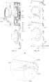
FIG. 1 is a front view of a laundry processing device according to an embodiment of the present application; -
FIG. 2 is a perspective view of a laundry processing device according to an embodiment of the present application; -
FIG. 3 is a structural schematic view of a cabinet of a laundry processing device according to an embodiment of the present application; -
FIG. 4 is an exploded view of a structure illustrated inFIG. 3 ; -
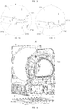
FIG. 5 is an exploded view of a support frame of a laundry processing device according to an embodiment of the present application; -
FIG. 6 is an enlarged view of portion A illustrated inFIG. 5 ; -
FIG. 7 is an enlarged view of portion B illustrated inFIG. 5 ; -
FIG. 8 is an enlarged view of portion C illustrated inFIG. 5 ; -
FIG. 9 is an assembly diagram of the support frame illustrated inFIG. 5 ; -
FIG. 10 is an exploded view of a support frame of a laundry processing device according to another embodiment of the present application; -
FIG. 11 is an assembly diagram of the support frame illustrated inFIG. 10 ; -
FIG. 12 is an enlarged view of portion X illustrated inFIG. 11 ; -
FIG. 13 is an exploded view of a door assembly of a laundry processing device inFIG. 3 according to an embodiment of the present application; -
FIG. 14 is a structural schematic view of a door assembly of a laundry processing device inFIG. 3 according to an embodiment of the present application; -
FIG. 15 is an enlarged view of portion D illustrated inFIG. 14 ; -
FIG. 16 is an enlarged view of portion E illustrated inFIG. 14 ; -
FIG. 17 is an enlarged view of portion F illustrated inFIG. 14 ; -
FIG. 18 is a structural schematic view of a drying module of a laundry processing device according to an embodiment of the present application from a perspective; -
FIG. 19 is a structural schematic view of a drying module of a laundry processing device according to an embodiment of the present application from another perspective; -
FIG. 20 is a structural schematic view of a reinforcing plate of a laundry processing device according to an embodiment of the present application; -
FIG. 21 is an enlarged view of portion G illustrated inFIG. 20 ; -
FIG. 22 is an enlarged view of portion H illustrated inFIG. 20 ; -
FIG. 23 is a top view of a reinforcing plate illustrated inFIG. 20 ; -
FIG. 24 is an assembly diagram of a reinforcing plate and a seat of a drying unit; -
FIG. 25 is a bottom view of a structure illustrated inFIG. 24 ; -
FIG. 26 is a side view of a structure illustrated inFIG. 24 ; -
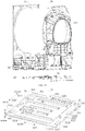
FIG. 27 is an assembly diagram of a support frame and a support structure of a laundry processing device according to an embodiment of the present application; -
FIG. 28 is an enlarged view of portion I illustrated inFIG. 27 ; -
FIG. 29 is an exploded view of a support frame and a support structure of a laundry processing device according to an embodiment of the present application; -
FIG. 30 is an enlarged view of portion J illustrated inFIG. 29 ; -
FIG. 31 is a structural schematic view of a frame connecting member of a laundry processing device according to an embodiment of the present application; -
FIG. 32 is an exploded view of a support frame of a laundry processing device according to an embodiment of the present application; -
FIG. 33 is an assembly view of a part of a support frame of a laundry processing device according to an embodiment of the present application; -
FIG. 34 is a top view of a structure illustrated inFIG. 33 ; -
FIG. 35 is another assembly view of a part of a support frame of a laundry processing device according to an embodiment of the present application; -
FIG. 36 is an enlarged view of portion K illustrated inFIG. 35 ; -
FIG. 37 is an enlarged view of portion L illustrated inFIG. 35 ; -
FIG. 38 is a top view of a structure illustrated inFIG. 35 ; -
FIG. 39 is an enlarged view of portion M illustrated inFIG. 38 ; -
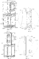
FIG. 40 is a structural schematic view of a side panel and a panel connecting member of a laundry processing device according to an embodiment of the present application; -
FIG. 41 is an enlarged view of portion N illustrated inFIG. 40 ; -
FIG. 42 is a structural schematic view of a panel connecting member of a laundry processing device according to an embodiment of the present application; - Reference numerals:
-
laundry processing device 100; -
cabinet 10; -
support frame 11; first accommodatingspace 1101; secondaccommodating space 1102;frame connecting hole 1104;frame perforation 1105;frame positioning hole 1106; - base 111;
bottom plate 1111;side enclosure plate 1112; second hinge mounting seat 1113 (1184); - third
vertical beam 112; - fourth
vertical beam 113; firstaccommodating recess 1131; snappinghole 11311; secondaccommodating recess 1132; first fixingperforation 11321; second fixingperforation 11322; first connectingsheet 1133;notch 11331;first perforation 11332; second connectingsheet 1134;second perforation 11341; - second
vertical beam 114; second lowervertical beam 1141; second uppervertical beam 1142; verticalbeam connecting sheet 11421; - first
vertical beam 115; first lowervertical beam 1151; first uppervertical beam 1152; - connecting
cross beam 117; snappingtongue 1171; firsthinge mounting seat 1172; - top connecting
frame 118; first connectingflange 1182;insertion sheet 11821; first throughhole 11822; second connectingflange 1183; second throughhole 11831; -
front panel 12;opening 1201; mountingrecess 1202; -
panel mounting portion 121;panel connecting hole 1211;panel perforation 1212;panel positioning hole 1213; -
panel connecting member 122,panel connecting portion 1221, connectingperforation 12211, connectingpost 1222,leg 12221,positioning post 1223, connectingprotrusion 1224,groove 1225; -
side panel 13,panel covering portion 131, snappingslot 1311,top panel 14; -
door assembly 15; -
first door 151;second door 152; mountingcavity 1520; mountingopening 1521;cover plate 1522;control panel 1523; -
intermediate hinge 153;intermediate mounting portion 1531, intermediate connectingportion 1532,upper fixing shaft 1533;lower fixing shaft 1534; -
first end hinge 154, first endface mounting portion 1541; first endface connecting portion 1542; lower connectingshaft 1543; -
second end hinge 155, second endface mounting portion 1551; second endface connecting portion 1552; upper connectingshaft 1553; - first
laundry processing module 20; firstlaundry processing tub 21; - second
laundry processing module 30; secondlaundry processing tub 311;laundry access port 311; -
support structure 312; second connectinghole 3121; -
frame connecting member 313; first connectinghole 3131; first fixingprotrusion 3132; second fixingprotrusion 3133; connectingbody 3134; connectingarm 3135; -
seat 32;suction area 321;blower mounting cavity 322; heatpump mounting cavity 323; - reinforcing
plate 33; raisedring 3301;first plate portion 331;first vent hole 3311; reinforcingrecess 3313;second plate portion 332;second vent hole 3321; reinforcingprotrusion 3323; mountingboss 3324; mountinghole 3325; fixingflange 333; fixinghole 3331;insertion hole 3332; first mountingflange 334; second mountingflange 335;avoidance notch 336. - Embodiments of the present application will be described in detail and examples of the embodiments will be illustrated in the drawings, where same or similar reference numerals are used to indicate same or similar members or members with same or similar functions. The embodiments described herein with reference to drawings are explanatory, illustrative, and only used to generally understand the present application. The embodiments shall not be construed to limit the present application.
- A
laundry processing device 100 according to embodiments of the present application will be described in the following with reference toFIGS. 1 to 42 . - As illustrated in
FIGS. 1 to 12 , asupport frame 11 according to embodiments of the present application includes abase 111 and a vertical beam. The vertical beam extends upwards from thebase 111. A plurality of vertical beams are provided, and at least part of the vertical beams is formed by detachably connecting at least two sub-units. - In the
support frame 11 according to embodiments of the present application, at least part of the vertical beams is formed by detachably connecting at least two sub-units. Thus, after the two sub-units are separated, an unobstructed large mounting space is defined, facilitating mounting of components. For example, if thesupport frame 11 is applied in thelaundry processing device 100, a large mounting space for mounting a laundry processing module can be defined by thesupport frame 11 after the sub-units of the vertical beam are separated. After completion of mounting the laundry processing module, the remaining sub-units are assembled, facilitating assembly. Furthermore, compared to asupport frame 11 in the related art, the present embodiment further enhances strength of thesupport frame 11 without affecting mounting of components. - According to an embodiment of the present application, the
base 111 is formed into asquare base 111. Four vertical beams are provided, i.e. a firstvertical beam 115, a secondvertical beam 114, a thirdvertical beam 112 and a fourthvertical beam 113. The four vertical beams are formed to extend upwards from four corners of thesquare base 111, such that the four vertical beams are utilized to define an accommodating space between them. - In some embodiments, two corners located at a side of the
square base 111 are provided with the firstvertical beam 115 and the secondvertical beam 114 respectively, and the firstvertical beam 115 and/or the secondvertical beam 114 are formed by detachably connecting at least two sub-units. That is, one of the firstvertical beam 115 and the secondvertical beam 114 is formed by detachably connecting at least two sub-units; or each of the firstvertical beam 115 and the secondvertical beam 114 is formed by detachably connecting at least two sub-units. - According to an optional embodiment of the present application, the first
vertical beam 115 is formed by detachably connecting two sub-units. The two sub-units of the firstvertical beam 111 are a first lowervertical beam 1151 and a first uppervertical beam 1152 respectively. The first lowervertical beam 1151 extends upwards from thesquare base 111, the first uppervertical beam 1152 extends upwards from the first lowervertical beam 1151, and the first uppervertical beam 1152 has a lower end detachably connected to an upper end of the first lowervertical beam 1151. - Specifically, as illustrated in
FIGS. 5 to 9 , the vertical beams include two short vertical beams and three long vertical beams. The two short vertical beams and the three long vertical beams all extend in an up-and-down direction. Lower ends of one short vertical beam and the three long vertical beams are connected to four corners of thesquare base 111 respectively, and the short vertical beam and lower portions of the three long vertical beams are utilized to define a firstaccommodating space 1101 located at a lower portion. The short vertical beam has a small height, thus it will not has an interference effect during mounting upper components. That is, a large mounting space is defined between the fourthvertical beam 113 and the secondvertical beam 114, and upper components can be easily assembled into a secondaccommodating space 1102 through the mounting space. After assembly of the component is completed, the lower end of the second short vertical beam is connected to the upper end of the first short vertical beam, greatly improving assembly efficiency and structural stability. - According to another optional embodiment of the present application, the second
vertical beam 114 is formed by detachably connecting two sub-units. The two sub-units of the secondvertical beam 114 are a second lowervertical beam 1141 extending upwards from thesquare base 111 and a second uppervertical beam 1142 extending upwards from the second lowervertical beam 1141, respectively. A lower end of the second uppervertical beam 1142 is detachably connected to an upper end of the second lowervertical beam 1141. - Specifically, as illustrated in
FIGS. 10 to 12 , the vertical beams include four short vertical beams and two long vertical beams. The four short vertical beams and the two long vertical beams all extend in the up-and-down direction. Lower ends of two short vertical beams and the two long vertical beams are connected to the four corners of thesquare base 111, such that the two short vertical beams and lower portions of the two long vertical beams define a firstaccommodating space 1101 located at a lower portion. When first upper vertical beam is separated from the first lower vertical beam, and the second upper vertical beam is separated from the second lower vertical beam, a large mounting space is defined in an upper portion of the frame. That is, a wide range of mounting space is defined behind the third vertical beam and the fourth vertical beam, and a laundry processing module can be conveniently passed through the mounting space and assembled into thesupport frame 11. After completion of assembly of the component, the lower ends of the two short vertical beams are connected to the upper ends of the two short vertical beams, greatly improving assembly efficiency and structural stability. Thus, the present embodiment can make the laundry processing module be assembled into the secondaccommodating space 1102 more conveniently. - In some examples, the lower end of the first upper
vertical beam 1152 is provided with a verticalbeam connecting sheet 11421 extending downwards, and the verticalbeam connecting sheet 11421 of the first uppervertical beam 1152 is connected to the upper end of the first lowervertical beam 1151 by a fastener. The lower end of the second uppervertical beam 1142 is provided with a verticalbeam connecting sheet 11421 extending downwards, and the verticalbeam connecting sheet 11421 of the second uppervertical beam 1142 is connected to the upper end of the second lowervertical beam 1141 by a fastener. For example, the verticalbeam connecting sheet 11421 defines a perforation adapted for passage of the fastener, facilitating connection. - In some examples, the vertical
beam connecting sheet 11421 of the first uppervertical beam 1152 is bent outwards and extends downwards relative to the first uppervertical beam 1152, such that at least part of an outer side of the upper end of the first lowervertical beam 1151 is covered by the verticalbeam connecting sheet 11421. The verticalbeam connecting sheet 11421 of the second uppervertical beam 1142 is bent outwards and extends downwards relative to the second uppervertical beam 1142, such that at least part of an outer side of the upper end of the second lowervertical beam 1141 is covered by the verticalbeam connecting sheet 11421. This not only facilitates the connection, but also ensures the connection reliability and stability between them. - According to an embodiment of the present application, the
square base 111 has abottom plate 1111 and fourside enclosure plates 1112 connected to sides of thebottom plate 1111. Lower ends of two adjacent vertical beams are connected by theside enclosure plate 1112, to ensure connection reliability and structural stability of thesupport frame 11. - According to an embodiment of the present application, the
support frame 11 further includes a plurality of connecting cross beams 117. Middle portions of two adjacent vertical beams are connected by the connectingcross beam 117, to further ensure connection reliability and structural stability of thesupport frame 11. - In some embodiments, two corners located at another side of the
square base 111 are provided with a thirdvertical beam 112 and a fourthvertical beam 113 respectively. Middle portions of outer surfaces of the thirdvertical beam 112 and the fourthvertical beam 113 each define a recessed firstaccommodating recess 1131, and two ends of at least one connectingcross beam 117 are disposed in the firstaccommodating recesses 1131 of the thirdvertical beam 112 and the fourthvertical beam 113, respectively, to prevent the connectingcross beam 117 from occupying excessive space and also to achieve positioning and mounting, which facilitates improvement of assembly efficiency of thesupport frame 11. Meanwhile, the design of the firstaccommodating recess 1131 also enhances strength of the vertical beam, and reduces its deformation and damage. - In some examples, a bottom wall of the first
accommodating recess 1131 defines asnapping hole 11311, and two ends of the connectingcross beam 117 are each provided with asnapping tongue 1171. The snappingtongue 1171 is bent towards the vertical beam (bent rearwards as illustrated inFIGS. 5 and6 ), and thesnapping tongue 1171 is inserted downwards into the snappinghole 11311, to mount the connectingcross beam 117 to the thirdvertical beam 112 and the fourthvertical beam 113. In some specific examples, the snappingtongue 1171 may have a hook shape, to hang the connectingcross beam 117 on the two vertical beams. - According to further embodiments of the present application, the
support frame 11 further includes a top connectingframe 118. The top connectingframe 118 is connected to the upper end of the vertical beam. At least part of the top connectingframe 118 is integrally formed with one sub-unit of the vertical beam from the same plate using a bending forming process. - Referring to
FIGS. 5 and10 , the top connectingframe 118 is connected to the upper end of each of the first uppervertical beam 1152, the second uppervertical beam 1142, the thirdvertical beam 112 and the fourthvertical beam 113. - It could be understood that, the at least part of the top connecting
frame 118 is formed by bending one sub-unit of the firstvertical beam 115 and/or the secondvertical beam 114. - Specifically, in an example illustrated in
FIG. 5 , a cross beam of the top connectingframe 118 extending in a front-and-rear direction is integrally formed with the first uppervertical beam 1152 from the same plate by using a bending forming process. Before the first uppervertical beam 1152 is connected to the first lowervertical beam 1151, a mounting space having a large opening is defined by upper portions of the thirdvertical beam 112, the fourthvertical beam 113 and the secondvertical beam 114, such that a component to be assembled can be conveniently mounted in the secondaccommodating space 1102. After completion of assembly, the first uppervertical beam 1152 which is connected with the top connectingframe 118 is connected to the first lowervertical beam 1151. The operation is simple, facilitating improvement of the assembly efficiency. - In an example illustrated in
FIG. 10 , a cross beams of the top connectingframe 118 extending in the front-and-rear direction and located at a right side is integrally formed with the first uppervertical beam 1152 from the same plate by using a bending forming process, and a cross beam of the top connectingframe 118 extending in the front-and-rear direction and located at a left side is integrally formed with the second uppervertical beam 1142 from the same plate by using a bending forming process. Before the first uppervertical beam 1152 is connected to the first lowervertical beam 1151 and the second uppervertical beam 1142 is connected to the second lowervertical beam 1141, only the thirdvertical beam 112, the fourthvertical beam 113 and the four connectingcross beams 117 are relied on to provide support for the component to be assembled. As this is not a closed structure and will not interfere with or block the component to be assembled during assembly, the mounting of the component to be assembled is further facilitated. After completion of assembly, the first uppervertical beam 1152 and the second uppervertical beam 1142, which are connected with the top connectingframe 118, are connected to the first lowervertical beam 1151 and the second lowervertical beam 1141, respectively. The operation is simple, facilitating improvement of assembly efficiency. - In some embodiments, two corners located at another side of the
square base 111 are provided with a thirdvertical beam 112 and a fourthvertical beam 113, respectively. The upper end of at least one of the thirdvertical beam 112 and the fourthvertical beam 113 defines anotch 11331 recessed downwards, the top connectingframe 118 has aninsertion sheet 11821 bent outwards, and theinsertion sheet 11821 is inserted in thenotch 11331. - Specifically, as illustrated in
FIGS. 5 and7-8 , the upper end of the fourthvertical beam 113 defines anotch 11331 recessed downwards, and correspondingly, the corner of the top connectingframe 118 located at the front right has aninsertion sheet 11821 bent outwards. The corner of the top connectingframe 118 located at the front right is snap-fitted with the upper end of the fourthvertical beam 113 through fit between theinsertion sheet 11821 and thenotch 11331. Furthermore, the upper end of the thirdvertical beam 112 is also snap-fitted with the corner of the top connectingframe 118 located at the front left through fit between theinsertion sheet 11821 and thenotch 11331. The connection is reliable and stable. - In some embodiments, the upper end of at least one of the third
vertical beam 112 and the fourthvertical beam 113 has a first connectingsheet 1133 and a second connectingsheet 1134 arranged at a preset angle. The top connectingframe 118 has a first connectingflange 1182 and a second connectingflange 1183 that extend downwards, and the first connectingflange 1182 and the second connectingflange 1183 are arranged at a preset angle. The aforementioned preset angle may be 90 degrees, and so on. - As illustrated in
FIGS. 7 and 8 , the upper end of the fourthvertical beam 113 has the first connectingsheet 1133 and the second connectingsheet 1134, and the corner of the top connectingframe 118 located at the front right has the first connectingflange 1182 and the second connectingflange 1183. The first connectingflange 1182 is spaced apart from second connectingflange 1183. The first connectingsheet 1133 is disposed at an outer side of the connectingflange 1182. The second connectingsheet 1134 is inserted through a gap between the first connectingflange 1182 and the second connectingflange 1183, to be disposed at an inner side of the second connectingflange 1183, such that the fourthvertical beam 113 and the top connectingframe 118 are further snap-fitted, and connection reliability and stability between them are further ensured. - In some examples, the
notch 11331 is defined in the first connectingsheet 1133, and theinsertion sheet 11821 is provided to the first connectingflange 1182. That is, connection reliability and stability of the top connectingframe 118 and the firstvertical beam 115 can be ensured by interactions between the first connectingsheet 1133 and the first connectingflange 1182, between the second connectingsheet 1134 and the second connectingflange 1183, and between thenotch 11331 and theinsertion sheet 11821. - In some specific examples, the first connecting
sheet 1133 defines afirst perforation 11332, and the first connectingflange 1182 defines a first throughhole 11822. The first throughhole 11822 corresponds in position to thefirst perforation 11332, and the number of thefirst perforations 11332 is equal to the number of the first throughholes 11822. The first connectingsheet 1133 and the first connectingflange 1182 are connected by a fastener passing through thefirst perforation 11332 and the first throughhole 11822, to further ensure the connection reliability and stability of the top connectingframe 118 and the long vertical beam. - In some specific examples, the second connecting
sheet 1134 defines asecond perforation 11341, and the second connectingflange 1183 defines a second throughhole 11831. The second throughhole 11831 corresponds in position to thesecond perforation 11341, and the number of the second throughholes 11831 is equal to the number of thesecond perforations 11341. The second connectingsheet 1134 and the second connectingflange 1183 are connected by a fastener passing through thesecond perforation 11341 and the second throughhole 11831, to further ensure the connection reliability and stability of the top connectingframe 118 and the long vertical beam. - The
laundry processing device 100 according to embodiments of the present application includes a firstlaundry processing module 20, a secondlaundry processing module 30 and asupport frame 11 according to the above embodiments. Thesupport frame 11 defines therein a firstaccommodating space 1101 for placement of the firstlaundry processing module 20 and a secondaccommodating space 1102 for placement of the secondlaundry processing module 30. - In the
laundry processing device 100 according to embodiments of the present application, by employing the above-describedsupport frame 11, a large mounting space can be defined, such that the secondlaundry processing module 30 can be conveniently assembled in the secondaccommodating space 1102. After completion of assembly of the secondlaundry processing module 30, the remaining sub-units are then assembled. The assembly is convenient which facilitates improvement of assembly efficiency. The number of the components can be reduced to save redundant connectors, and improvement of structural strength of thesupport frame 11 can be facilitated. - In combination with
FIGS. 1 to 42 , a specific embodiment of thelaundry processing device 100 according to the present application will be described in detail below. - As illustrated in
FIGS. 1 to 4 , thelaundry processing device 100 includes acabinet 10, adoor assembly 15, a firstlaundry processing module 20 and a secondlaundry processing module 30. - The
cabinet 10 serves as a frame structure of thelaundry processing device 100. Thecabinet 10 includes asupport frame 11. Thesupport frame 11 includes asquare base 111, a plurality of connectingcross beams 117, a top connectingframe 118, and four vertical beams, i.e. a firstvertical beam 115, a secondvertical beam 114, a thirdvertical beam 112 and a fourthvertical beam 113. The four vertical beams extend upwards from four corners of thesquare base 111, respectively. The firstvertical beam 115 and the secondvertical beam 114 are disposed at two corners of thesquare base 111 located at a rear portion, and the thirdvertical beam 112 and the fourthvertical beam 113 are located at two corners of thesquare base 111 located at a front portion. - The
square base 111 includes abottom plate 1111 and fourside enclosure plates 1112 disposed around sides of aseat 32. Lower ends of two adjacent vertical beams are connected by theside enclosure plate 1112. Middle portions of two adjacent vertical beams are connected by the connectingcross beam 117. The upper end of each vertical beam is connected to the four corners of the top connectingframe 118. - A first
accommodating space 1101 is defined between the top connectingframe 118, the plurality of connectingcross beams 117 and lower portions of the four vertical beams for assembly of the firstlaundry processing module 20. A secondaccommodating space 1102 is defined between the top connectingframe 118, the plurality of connectingcross beams 117 and upper portions of the four vertical beams for assembly of the secondlaundry processing module 30. - As illustrated in
FIGS. 5 to 9 , in some optional examples, the firstvertical beam 115 includes two short vertical beams, i.e. a first lowervertical beam 1151 extending upwards from thesquare base 111 and a first uppervertical beam 1152 extending upwards from the first lowervertical beam 1151. The first uppervertical beam 1152 is integrally formed with a cross beam of the top connectingframe 118 extending in the front-and-rear direction and located at the right side from the same plate by using a bening forming process. That is, in the present embodiment, the first uppervertical beam 1152 and a portion of the top connectingframe 118 are integrally formed, and they do not need to be connected by a connection structure. A lower end of the first uppervertical beam 1152 is detachably connected to an upper end of the first lowervertical beam 1151, and to the connectingcross beam 117. Each of the secondvertical beam 114, the thirdvertical beam 112 and the fourthvertical beam 113 is a long vertical beam. - Before assembly of the second
laundry processing module 30, the first lowervertical beam 1151, the secondvertical beam 114, the thirdvertical beam 112 and the fourthvertical beam 113 are assembled by thesquare base 111 and the plurality of connectingcross beams 117, such that upper portions of the secondvertical beam 114, the thirdvertical beam 112 and the fourthvertical beam 113 define an unobstructed large mounting space to facilitate assembly of the secondlaundry processing module 30. After completion of the assembly, the first uppervertical beam 1152, which is connected with the top connectingframe 118, is connected to the first lowervertical beam 1151. - As illustrated in
FIGS. 10 to 12 , in some other optional examples, the firstvertical beam 115 and the secondvertical beam 114 each includes two short vertical beams. That is, the firstvertical beam 115 includes a first lowervertical beam 1151 extending upwards from thesquare base 111 and a first uppervertical beam 1152 extending upwards from the first lowervertical beam 1151, and the secondvertical beam 114 includes a second lowervertical beam 1141 extending upwards from thesquare base 111 and a second uppervertical beam 1142 extending upwards from the second lowervertical beam 1141. - A cross beam of the top connecting
frame 118 extending in the front-and-rear direction and located at the right side is integrally formed with the first uppervertical beam 1152 from the same plate using a bending forming process, and a cross beam of the top connectingframe 118 extending in the front-and-rear direction and located at the left side is integrally formed with the second uppervertical beam 1142 from the same plate using a bending forming process. That is, in the present embodiment, the first uppervertical beam 1152 and a portion of the top connectingframe 118 are integrally formed, the second uppervertical beam 1142 and another portion of the top connectingframe 118 are integrally formed, and they do not need to be connected by a connection structure. The lower end of the first uppervertical beam 1152 is detachably connected to the upper end of the first lowervertical beam 1151 and they are connected to the connectingcross beam 117 separately. The lower end of the second uppervertical beam 1142 is connected to the upper end of the second lowervertical beam 1141 and they are connected to the connectingcross beam 117 separately. Each of the thirdvertical beam 112 and the fourthvertical beam 113 is a long vertical beam. - Before assembly of the second
laundry processing module 30, the first lowervertical beam 1151, the second lowervertical beam 1141, the thirdvertical beam 112 and the fourthvertical beam 113 are assembled by thesquare base 111 and the plurality of connectingcross beams 117, then the secondlaundry processing module 30 is assembled with the thirdvertical beam 112, the fourthvertical beam 113 and the connectingcross beams 117, and finally, the first uppervertical beam 1152 and the second uppervertical beam 1142, which are connected with the top connectingframe 118, are connected to the first lowervertical beam 1151 and the second lowervertical beam 1141, respectively. - As regard to connection manner between the upper vertical beam and the lower vertical beam, it will be described below by taking the second upper
vertical beam 1142 and the second lowervertical beam 1141 as an example. As illustrated inFIGS. 11 and 12 , the lower end of the second uppervertical beam 1142 is provided with a verticalbeam connecting sheet 11421 extending downwards. The verticalbeam connecting sheet 11421 of the second uppervertical beam 1142 is bent outwards and extends downwards relative to the second uppervertical beam 1142, such that at least part of an outer side of the upper end of the second lowervertical beam 1141 is covered by the verticalbeam connecting sheet 11421. The verticalbeam connecting sheet 11421 of the second uppervertical beam 1142 is connected to the upper end of the second lowervertical beam 1141 by a fastener. The connection is convenient, and the connection reliability and stability of them are ensured. - As regard to connection manner between the vertical beam and the connecting
cross beam 117, it will be described below by taking the thirdvertical beam 112 and the fourthvertical beam 113 as an example. As illustrated inFIGS. 5 and6 , middle portions of front side surfaces of the thirdvertical beam 112 and the fourthvertical beam 113 each define a recessed firstaccommodating recess 1131. A bottom wall of each firstaccommodating recess 1131 defines asnapping hole 11311. Two ends of the connectingcross beam 117 are each provided with asnapping tongue 1171 bent downwards. The two ends of the connectingcross beam 117 are disposed in the firstaccommodating recesses 1131 of the thirdvertical beam 112 and the fourthvertical beam 113, respectively, and thesnapping tongue 1171 is inserted downwards into the snappinghole 11311, to mount the connectingcross beam 117 to the thirdvertical beam 112 and the fourthvertical beam 113. - As regard to connection manner between the vertical beam and the top connecting
frame 118, it will be described below by taking the fourthvertical beam 113 as an example. As illustrated inFIGS. 5 ,7 and 8 , the upper end of the fourthvertical beam 113 has a first connectingsheet 1133 and a second connectingsheet 1134 arranged at an angle of 90 degrees. The first connectingsheet 1133 defines anotch 11331 and afirst perforation 11332, and the second connectingsheet 1134 defines asecond perforation 11341. A corner of the top connectingframe 118 corresponding in position to the fourthvertical beam 113 is provided with a first connectingflange 1182 and a second connectingflange 1183 that extend downwards. The first connectingflange 1182 is spaced apart from the second connectingflange 1183. The first connectingflange 1182 is provided with aninsertion sheet 11821 bent outwards and a first throughhole 11822, and the second connectingflange 1183 defines a second throughhole 11831. - When assembling, the first connecting
sheet 1133 is disposed at an outer side of the first connectingflange 1182, the second connectingsheet 1134 is inserted through a gap between the first connectingflange 1182 and the second connectingflange 1183, and theinsertion sheet 11821 is fitted in thenotch 11331. The first connectingsheet 1133 and the first connectingflange 1182 are connected by a fastener passing through thefirst perforation 11332 and the first throughhole 11822, and the second connectingsheet 1134 and the second connectingflange 1183 are connected by a fastener passing through thesecond perforation 11341 and the second throughhole 11831, to ensure connection reliability and stability of the top connectingframe 118 and the fourthvertical beam 113. - As illustrated in
FIGS. 32 to 42 , the frame structure further includes a plurality of panels, i.e. afront panel 12, twoside panels 13, a back panel and atop panel 14. Thefront panel 12 covers a front region of thesupport frame 11, and thefront panel 12 defines twoopenings 1201 spaced in the up-and-down direction. Positions of the twoopenings 1201 correspond to positions oflaundry access ports 311 of the firstlaundry processing module 20 and the secondlaundry processing module 30. The back panel covers a rear region of thesupport frame 11, and the twoside panels 13 cover a left region and a right region of thesupport frame 11. - The connection manner of the
front panel 12, theside panel 13 located at the left side and thesupport frame 11 will be described in detail below. The thirdvertical beam 112 is disposed at a corner of thesquare base 111 located at the front left. A front side surface of the thirdvertical beam 112 defines aframe connecting hole 1104, aframe positioning hole 1106, and aframe perforation 1105. A left side of thefront panel 12 has apanel mounting portion 121 recessed relative to an outer surface of thefront panel 12. Thepanel mounting portion 121 defines apanel connecting hole 1211 corresponding in position to theframe connecting hole 1104, apanel positioning hole 1213 corresponding in position to theframe positioning hole 1106, and apanel perforation 1212 corresponding in position to theframe perforation 1105. A front side of theside panel 13 located at the left side has apanel covering portion 131 bent towards thefront panel 12, and an inner side of thepanel covering portion 131 defines asnapping slot 11311. - The
panel mounting portion 121 is connected to the thirdvertical beam 112 by apanel connecting member 122 passing through thepanel connecting hole 1211 and theframe connecting hole 1104. Thepanel connecting member 122 includes apanel connecting portion 1221, apositioning post 1223 and a connectingpost 1222. Thepanel connecting portion 1221 is provided with a connectingprotrusion 1224 to define agroove 1225 recessed downwards. The connectingpost 1222 includes twolegs 12221 that are spaced apart. - When assembling, the
panel mounting portion 121 of thefront panel 12 can be fixed to the thirdvertical beam 112 by a screw, then the twolegs 12221 of thepanel connecting member 122 are squeezed to allow the connectingpost 1222 to pass through thepanel connecting hole 1211 and theframe connecting hole 114 sequentially, and the twolegs 12221 are released to achieve an anti-separation effect. Furthermore, thepositioning post 1223 is passed through the frame positioning hole 1206 and thepanel positioning hole 1213, and a fastener is passed through the connectingperforation 12211, thepanel perforation 1212 and theframe perforation 1105 to further ensure connection reliability of thepanel connecting member 122, thepanel mounting portion 121 and the thirdvertical beam 112. Finally, theside panel 13 is mounted such that thepanel covering portion 131 of theside panel 13 covers thepanel mounting portion 121 of thefront panel 12, and then theside panel 13 is pushed downwards or the gravity of theside panel 13 is utilized to snap an upper edge of thesnapping slot 1311 of thepanel covering portion 131 into thegroove 1225 of thepanel connecting member 122. Thus, thepanel covering portion 131 of theside panel 13 will shield thepanel mounting portion 121 of thefront panel 12, and the screw andpanel connecting member 122 on thepanel mounting portion 121, without affecting appearance of the frame structure. - As illustrated in
FIGS. 9 and33 , a front surface of the connectingcross beam 117 located between the thirdvertical beam 112 and the fourthvertical beam 113 is provided with a firsthinge mounting seat 1172. A front surface of theside enclosure plate 1112 located between the thirdvertical beam 112 and the fourthvertical beam 113 is provided with a secondhinge mounting seat 1113. An upper surface of the top connectingframe 118 is provided with a secondhinge mounting seat 1184. Middle portion of thefront panel 12 defines a mountingrecess 1202. A bottom wall of the mountingrecess 1202 defines a mountinghole 3325 corresponding in position to a perforation in the firsthinge mounting seat 1172. A lower portion of thefront panel 12 also defines a mountingrecess 1202, and a bottom wall of this mountingrecess 1202 defines a mountinghole 3325 corresponding in position to a perforation in the second hinge mounting seat 1113 (1184). - As illustrated in
FIGS. 13 to 17 , thedoor assembly 15 of thelaundry processing device 100 includes afirst door 151 and asecond door 152. Thefirst door 151 is located below thesecond door 152, and an upper end of thefirst door 151 and a lower end of thesecond door 152 are connected to thesupport frame 11 by anintermediate hinge 153. Specifically, theintermediate hinge 153 includes anintermediate mounting portion 1531 and an intermediate connectingportion 1532. Theintermediate mounting portion 1531 is disposed in the mountingrecess 1202 and is connected to the firsthinge mounting seat 1172 by a fastener, to be fixed to the front portion of thesupport frame 11. The intermediate connectingportion 1532 is connected to theintermediate mounting portion 1531. An upper surface of the intermediate connectingportion 1532 has anupper fixing shaft 1533 extending upwards, and theupper fixing shaft 1533 is fitted with thesecond door 152. A lower surface of the intermediate connectingportion 1532 has alower fixing shaft 1534 extending downwards, and thelower fixing shaft 1534 is fitted with thefirst door 151. - A lower end of the
first door 151 is connected to the lower end of thesupport frame 11 by afirst end hinge 154. Thefirst end hinge 154 includes a first endface mounting portion 1541 and a first endface connecting portion 1542. The first endface mounting portion 1541 is provided in the mountingrecess 1202 and is connected to the secondhinge mounting seat 1113 by a fastener, to be fixed to the lower portion of thesupport frame 11. The first endface connecting portion 1542 is connected to the first endface mounting portion 1541. The first endface connecting portion 1542 has a lower connectingshaft 1543 extending upwards, and the lower connectingshaft 1543 is fitted with a lower end face of thefirst door 151. - An upper end of the
second door 152 is connected to the upper end of thesupport frame 11 by asecond end hinge 155. Thesecond end hinge 155 includes a second endface mounting portion 1551 and a second endface connecting portion 1552. The second endface mounting portion 1551 is connected to the secondhinge mounting seat 1184 on the upper surface of the top connectingframe 118 by a fastener, to be fixed to an upper portion of thesupport frame 11. The second endface connecting portion 1552 is connected to the second endface mounting portion 1551, the second endface connecting portion 1552 has an upper connectingshaft 1553 extending downwards, and the upper connectingshaft 1553 is fitted with an upper end face of thesecond door 152. - As illustrated in
FIG. 13 , an inward side of thesecond door 152 defines a mountingopening 1521, acontrol panel 1523 is mounted in a mountingcavity 1520 of thesecond door 152 via the mountingopening 1521, and acover plate 1522 is adapted to detachably close the mountingopening 1521, such that thecontrol panel 1523 is closed in the mountingcavity 1520 of thesecond door 152. - The first
laundry processing module 20 includes a firstlaundry processing tub 21. The firstlaundry processing module 20 may be a washing module and is mounted in the firstaccommodating space 1101 located in the lower portion. The secondlaundry processing module 30 includes a secondlaundry processing tub 31. The secondlaundry processing module 30 may be a drying module and is mounted in a secondaccommodating space 1102 located at the upper portion. The drying module is provided with a control board in communication with thecontrol panel 1523. The operational environment of the drying module has relatively low moisture, and will not cause damage to the control board. - As illustrated in
FIGS. 18 to 26 , the drying module includes a drying unit and a reinforcingplate 33 provided below aseat 32 of the drying unit. The drying module is connected to thesupport frame 11 by the reinforcingplate 33 pre-mounted on the drying unit, and a gap is defined between theseat 32 and thefront panel 12. - The
seat 32 of the drying unit includes asuction area 321 for mounting a cooling fan, ablower mounting cavity 322 and a heatpump mounting cavity 323. The reinforcingplate 33 defines a plurality offirst vent holes 3311 in communication with theblower mounting cavity 322, a plurality of second vent holes 3321 and anavoidance notch 336 corresponding in position to thesuction area 321. A peripheral edge of the reinforcingplate 33 is provided with a first mountingflange 334 bent upwards, for connecting with the connectingcross beam 117. The peripheral edge of the reinforcingplate 33 is further provided with asecond mounting flange 335 bent upwards and located at an inner side of the first mountingflange 334, for connecting with theseat 32 of the drying unit. - The reinforcing
plate 33 is substantially formed into a square plate member and includes afirst plate portion 331 and asecond plate portion 332 which is recessed relative to thefirst plate portion 331 and surrounds thefirst plate portion 331. A front portion of thesecond plate portion 332 forms an extension portion beyond the peripheral edge of theseat 32. The plurality of second vent holes 3321 are defined in the extension portion. A plurality of reinforcingrecesses 3313 are defined in thefirst plate portion 331 and spaced apart in the front-and-rear direction. Each reinforcingrecess 3313 extends in a left-and-right direction. A plurality of reinforcingprotrusions 3323 are provided to thesecond plate portion 332 and spaced apart in a circumferential direction of thefirst plate portion 331. The peripheral edge of the reinforcingplate 33 is further provided with a fixingflange 333 bent upwards. The fixingflange 333 defines afixing hole 3331. The fixingflange 333 further defines aninsertion hole 3332 through its thickness direction. The reinforcingplate 33 is provided with a mountingboss 3324 close to the position of theinsertion hole 3332, and the top of the mountingboss 3324 defines a mountinghole 3325. For example, thesupport structure 312 has an insertion portion adapted to be inserted into theinsertion hole 3332, to connect the mountingboss 3324. - During the operation of the drying module, part of air located in the washing module flows into the
suction area 321 through theavoidance notch 336 and a gap between thesuction area 321 and thefront panel 12, for cooling the heat pump system. Furthermore, air between the drying module and the washing module can also achieve circulation through the plurality of second vent holes 3321. - As illustrated in
FIGS. 27 to 31 , the drying unit includes a drying tub andsupport structures 312 provided to a front end and a rear end of the drying tub. Thesupport structure 312 located at the front end of the drying tub is connected to the thirdvertical beam 112 and the fourthvertical beam 113 by twoframe connecting members 313. - The
frame connecting member 313 includes a connectingbody 3134 and two connectingarms 3135. The connectingbody 3134 extends in a length direction of the thirdvertical beam 112 or the fourthvertical beam 113. The two connectingarms 3135 are connected to two ends of the connectingbody 3134 and extend towards thesupport structure 312. The connectingarms 3135 are recessed inwards towards the secondaccommodating space 1102 relative to the connectingbody 3134. Each connectingarm 3135 defines a first connectinghole 3131. The connectingbody 3134 is provided with afirst fixing protrusion 3132 and asecond fixing protrusion 3133 that are bent towards the thirdvertical beam 112 or the fourthvertical beam 113. - The
support structure 312 defines a second connectinghole 3121 corresponding in portion to the first connectinghole 3131, and theframe connecting member 313 and thesupport structure 312 are connected by a fastener passing through the first connectinghole 3131 and the second connectinghole 3121. - A front side surface of each of the third
vertical beam 112 and the fourthvertical beam 113 defines a recessed secondaccommodating recess 1132. A bottom wall of the secondaccommodating recess 1132 in the thirdvertical beam 112 defines a first fixingperforation 11321, and a bottom wall of the secondaccommodating recess 1132 in the fourthvertical beam 113 defines a first fixingperforation 11321. Theframe connecting member 313 is provided in the secondaccommodating recess 1132. Thefirst fixing protrusion 3132 of theframe connecting member 313 provided on the thirdvertical beam 112 is fitted in the first fixingperforation 11321 and thesecond fixing protrusion 3133 thereof is fitted in the second fixingperforation 11322, to achieve connection of the thirdvertical beam 112 and theframe connecting member 313. Thefirst fixing protrusion 3132 of theframe connecting member 313 provided on fourthvertical beam 113 is fitted in the first fixingperforation 11321, and thesecond fixing protrusion 3133 thereof is fitted in the second fixingperforation 11322, to achieve connection of the fourthvertical beam 113 and theframe connecting member 313. - In the specification, it is to be understood that terms such as "central," "longitudinal," "lateral," "length," "width," "thickness," "upper," "lower," "front," "rear," "left," "right," "vertical," "horizontal," "top," "bottom," "inner," "outer," "axial," "radial" and "circumferential" should be construed to refer to the orientation as then described or as shown in the drawings under discussion. These relative terms are for convenience of description and do not require that the present disclosure be constructed or operated in a particular orientation.
- Other constitutions and operations of the
air conditioner 100 according to embodiments of the present application are well known by those skilled in the art, which will not be described in detail herein. - Reference throughout this specification to "an embodiment," "some embodiments," "an illustrative embodiment," "an example," "a specific example," or "some examples," means that a particular feature, structure, material, or characteristic described in connection with the embodiment or example is included in at least one embodiment or example of the present application. Thus, the appearances of the phrases in various places throughout this specification are not necessarily referring to the same embodiment or example of the present disclosure. Furthermore, the particular features, structures, materials, or characteristics may be combined in any suitable manner in one or more embodiments or examples.
- Although embodiments of the present application have been shown and illustrated, it shall be understood by those skilled in the art that various changes, modifications, alternatives and variants without departing from the principle of the present application are acceptable. The scope of the present application is defined by the claims or the like.
Claims (19)
- A support frame, comprising:a base; anda vertical beam extending upwards from the base, a plurality of vertical beams being provided, at least part of the vertical beams being formed by detachably connecting at least two sub-units.
- The support frame according to claim 1, wherein the base is formed into a square base, four vertical beams are provided, and the four vertical beams are formed to extend upwards from four corners of the square base.
- The support frame according to claim 2, wherein two corners located at a side of the square base are provided with a first vertical beam and a second vertical beam respectively, and the first vertical beam and/or the second vertical beam are formed by detachably connecting at least two sub-units.
- The support frame according to claim 3, wherein the first vertical beam is formed by detachably connecting two sub-units,
wherein the two sub-units of the first vertical beam are a first lower vertical beam extending upwards from the square base and a first upper vertical beam extending upwards from the first lower vertical beam, and the first upper vertical beam has a lower end detachably connected to an upper end of the first lower vertical beam. - The support frame according to claim 4, wherein the second vertical beam is formed by detachably connecting two sub-units,
wherein the two sub-units of the second vertical beam are a second lower vertical beam extending upwards from the square base and a second upper vertical beam extending upwards from the second lower vertical beam, and the second upper vertical beam has a lower end detachably connected to an upper end of the second lower vertical beam. - The support frame according to claim 5, wherein the lower end of each of the first upper vertical beam and the second upper vertical beam is provided with a vertical beam connecting sheet extending downwards,
wherein the vertical beam connecting sheet of the first upper vertical beam is connected to the upper end of the first lower vertical beam by a fastener, and the vertical beam connecting sheet of the second upper vertical beam is connected to the upper end of the second lower vertical beam by a fastener. - The support frame according to claim 6, wherein the vertical beam connecting sheet is bent outwards and extends downwards relative to the first upper vertical beam or the second upper vertical beam, such that at least part of an outer side of the upper end of the first lower vertical beam or the second lower vertical beam is covered by the vertical beam connecting sheet.
- The support frame according to any one of claims 2 to 7, wherein the square base has a bottom plate and four side enclosure plates connected to sides of the bottom plate, and lower ends of two adjacent vertical beams are connected by the side enclosure plate.
- The support frame according to any one of claims 2 to 8, further comprising a plurality of connecting cross beams, middle portions of two adjacent vertical beams are connected by the connecting cross beam.
- The support frame according to claim 9, wherein two corners located at another side of the square base are provided with a third vertical beam and a fourth vertical beam, respectively, middle portions of outer surfaces of the third vertical beam and the fourth vertical beam each define a recessed first accommodating recess, and two ends of at least one connecting cross beam are disposed in the first accommodating recesses of the third vertical beam and the fourth vertical beam respectively.
- The support frame according to claim 10, wherein a bottom wall of the first accommodating recess defines a snapping hole, the two ends of the connecting cross beam are each provided with a snapping tongue bent towards the vertical beam, and the snapping tongue is inserted downward into the snapping hole.
- The support frame according to any one of claims 3 to 7, further comprising:a top connecting frame connected to an upper end of the vertical beam,wherein at least part of the top connecting frame and one sub-unit of the vertical beam are integrally formed from a same plate using a bending forming process.
- The support frame according to claim 12, wherein the at least part of the top connecting frame is formed by bending one sub-unit of the first vertical beam and/or the second vertical beam.
- The support frame according to claim 12, wherein two corners located at another side of the square base are provided with a third vertical beam and a fourth vertical beam respectively, an upper end of at least one of the third vertical beam and the fourth vertical beam defines a notch recessed downwards, the top connecting frame has an insertion sheet bent outwards, and the insertion sheet is inserted in the notch.
- The support frame according to claim 14, wherein the upper end of at least one of the third vertical beam and the fourth vertical beam has a first connecting sheet and a second connecting sheet arranged at a preset angle, and the top connecting frame has a first connecting flange and a second connecting flange extending downwards and arranged at a preset angle,
wherein the first connecting flange and the second connecting flange are spaced apart, the first connecting sheet is disposed at an outer side of the first connecting flange, and the second connecting sheet is inserted through a gap between the first connecting flange and the second connecting flange to be disposed at an inner side of the second connecting flange. - The support frame according to claim 15, wherein the notch is defined in the first connecting sheet, and the insertion sheet is provided to the first connecting flange.
- The support frame according to claim 15, wherein the first connecting sheet defines a first perforation, and the first connecting flange defines a first through hole corresponding in position to the first perforation,
wherein the first connecting sheet and the first connecting flange are connected by a fastener passing through the first perforation and the first through hole. - The support frame according to claim 15, wherein the second connecting sheet defines a second perforation, and the second connecting flange defines a second through hole corresponding in position to the second perforation,
wherein the second connecting sheet and the second connecting flange are connected by a fastener passing through the second perforation and the second through hole. - A laundry processing device, comprising a first laundry processing module, a second laundry processing module and a support frame according to any one of claims 1 to 18,
wherein the support frame defines therein a first accommodating space for assembly of the first laundry processing module and a second accommodating space for assembly of the second laundry processing module.
Applications Claiming Priority (3)
| Application Number | Priority Date | Filing Date | Title |
|---|---|---|---|
| CN201920010370.1U CN209669546U (en) | 2019-01-03 | 2019-01-03 | Braced frame and device for clothing processing |
| CN201910005456.XA CN111394950B (en) | 2019-01-03 | 2019-01-03 | Support frame and clothes treating device |
| PCT/CN2019/084798 WO2020140352A1 (en) | 2019-01-03 | 2019-04-28 | Support frame and laundry processing device |
Publications (3)
| Publication Number | Publication Date |
|---|---|
| EP3907323A1 true EP3907323A1 (en) | 2021-11-10 |
| EP3907323A4 EP3907323A4 (en) | 2022-03-09 |
| EP3907323B1 EP3907323B1 (en) | 2025-02-12 |
Family
ID=71407250
Family Applications (1)
| Application Number | Title | Priority Date | Filing Date |
|---|---|---|---|
| EP19906936.0A Active EP3907323B1 (en) | 2019-01-03 | 2019-04-28 | Support frame and laundry processing device |
Country Status (3)
| Country | Link |
|---|---|
| US (1) | US12221734B2 (en) |
| EP (1) | EP3907323B1 (en) |
| WO (1) | WO2020140352A1 (en) |
Family Cites Families (15)
| Publication number | Priority date | Publication date | Assignee | Title |
|---|---|---|---|---|
| CN2136263Y (en) * | 1992-09-04 | 1993-06-16 | 赵志忠 | Miniature, heating and drying device |
| JPH08215485A (en) * | 1995-02-20 | 1996-08-27 | Matsushita Electric Ind Co Ltd | Washing machine |
| TR200300569A2 (en) * | 2003-04-30 | 2004-12-21 | Tolon Maki̇na Teksti̇l Gida Sanayi̇ Ve Ti̇caret Li̇mi̇ted Şi̇rketi̇ | Industrial type stacked washing and squeezing and drying machine. |
| DE202006017077U1 (en) | 2006-11-08 | 2007-03-01 | Korte, Hermann, Dipl.-Ing. | Storage and transport device, has admission sleeves which is provided with detachable locking means to strength and form-locking cooperating with support bar |
| US8616388B2 (en) * | 2011-06-07 | 2013-12-31 | Advance Caster & Wheel Co., Inc. | Adjustable shelving assembly |
| US10301756B2 (en) * | 2013-07-09 | 2019-05-28 | Haier Group Corporation | Dual-drum washing machine |
| US10024569B2 (en) * | 2013-10-10 | 2018-07-17 | William Christopher Duffy | Fire-rated modular duct assembly and improvements therein |
| CN103806251B (en) * | 2014-02-21 | 2016-04-20 | 惠而浦(中国)股份有限公司 | Box body of double-drum washing machine |
| CN203741597U (en) * | 2014-02-21 | 2014-07-30 | 合肥荣事达三洋电器股份有限公司 | Box body of double-drum washing machine |
| EP3124675B1 (en) * | 2015-07-27 | 2026-04-22 | Electrolux Appliances Aktiebolag | Washing and/or drying appliance |
| CN207537778U (en) * | 2017-10-20 | 2018-06-26 | 青岛海尔洗衣机有限公司 | A kind of clothes treatment device |
| CN208151705U (en) * | 2018-02-13 | 2018-11-27 | 青岛海尔滚筒洗衣机有限公司 | A kind of device for clothing processing shell structure and device for clothing processing |
| CN208151725U (en) * | 2018-02-13 | 2018-11-27 | 青岛海尔滚筒洗衣机有限公司 | A kind of back plate structure and device for clothing processing of device for clothing processing |
| CN208151704U (en) * | 2018-02-13 | 2018-11-27 | 青岛海尔滚筒洗衣机有限公司 | A kind of lateral plate structure and device for clothing processing of device for clothing processing |
| CN108301176B (en) * | 2018-04-10 | 2023-07-07 | 深圳市绿创青芒科技有限公司 | Multipurpose folding warm air clothes drying device and drying method |
-
2019
- 2019-04-28 WO PCT/CN2019/084798 patent/WO2020140352A1/en not_active Ceased
- 2019-04-28 US US17/420,392 patent/US12221734B2/en active Active
- 2019-04-28 EP EP19906936.0A patent/EP3907323B1/en active Active
Also Published As
| Publication number | Publication date |
|---|---|
| EP3907323B1 (en) | 2025-02-12 |
| WO2020140352A1 (en) | 2020-07-09 |
| US12221734B2 (en) | 2025-02-11 |
| BR112021013169A2 (en) | 2021-09-28 |
| EP3907323A4 (en) | 2022-03-09 |
| US20220081819A1 (en) | 2022-03-17 |
Similar Documents
| Publication | Publication Date | Title |
|---|---|---|
| US12203209B2 (en) | Frame assembly of clothes treatment apparatus and clothes treatment apparatus | |
| US5593219A (en) | Mainframe housing of a personal computer | |
| CN111394930B (en) | Clothes treating apparatus | |
| CN109487481B (en) | A clothing treatment device | |
| CN111394970B (en) | Reinforcement plate, clothes drying module and clothes treating device | |
| US12221734B2 (en) | Support frame and laundry processing device | |
| CN111394950B (en) | Support frame and clothes treating device | |
| JP3862847B2 (en) | Air conditioner electrical parts box | |
| CN111394952B (en) | Clothes treatment device | |
| CN209798343U (en) | Clothes treating device | |
| CN111394929A (en) | Clothes treating device | |
| CN107780166B (en) | Washing machine with low control panel seat | |
| CN111455609B (en) | Clothes treatment device | |
| CN212435818U (en) | A wall-mounted rivet embedded TV back shell and a TV | |
| CN111394951B (en) | Frame structure and clothes processing device | |
| CN111691152B (en) | Washing machine top cover, installation method and washing machine | |
| KR20030067256A (en) | Top cover fix structure of air conditioner | |
| WO2020140351A1 (en) | Laundry treatment device | |
| BR112021013169B1 (en) | SUPPORT FRAME, AND CLOTHES PROCESSING DEVICE | |
| CN207963098U (en) | The housing unit and air conditioner of air conditioner | |
| KR20030038031A (en) | Air conditioner | |
| CN218633031U (en) | Outdoor electric control cabinet | |
| CN219547355U (en) | Clothes treating apparatus | |
| CN215686863U (en) | Panel assembly and cooking utensil with same | |
| CN216672255U (en) | Power distribution cabinet convenient for heat dissipation |
Legal Events
| Date | Code | Title | Description |
|---|---|---|---|
| STAA | Information on the status of an ep patent application or granted ep patent |
Free format text: STATUS: THE INTERNATIONAL PUBLICATION HAS BEEN MADE |
|
| PUAI | Public reference made under article 153(3) epc to a published international application that has entered the european phase |
Free format text: ORIGINAL CODE: 0009012 |
|
| STAA | Information on the status of an ep patent application or granted ep patent |
Free format text: STATUS: REQUEST FOR EXAMINATION WAS MADE |
|
| 17P | Request for examination filed |
Effective date: 20210802 |
|
| AK | Designated contracting states |
Kind code of ref document: A1 Designated state(s): AL AT BE BG CH CY CZ DE DK EE ES FI FR GB GR HR HU IE IS IT LI LT LU LV MC MK MT NL NO PL PT RO RS SE SI SK SM TR |
|
| A4 | Supplementary search report drawn up and despatched |
Effective date: 20220204 |
|
| RIC1 | Information provided on ipc code assigned before grant |
Ipc: D06F 39/12 20060101AFI20220131BHEP |
|
| DAV | Request for validation of the european patent (deleted) | ||
| DAX | Request for extension of the european patent (deleted) | ||
| STAA | Information on the status of an ep patent application or granted ep patent |
Free format text: STATUS: EXAMINATION IS IN PROGRESS |
|
| 17Q | First examination report despatched |
Effective date: 20230728 |
|
| GRAP | Despatch of communication of intention to grant a patent |
Free format text: ORIGINAL CODE: EPIDOSNIGR1 |
|
| STAA | Information on the status of an ep patent application or granted ep patent |
Free format text: STATUS: GRANT OF PATENT IS INTENDED |
|
| INTG | Intention to grant announced |
Effective date: 20240930 |
|
| GRAS | Grant fee paid |
Free format text: ORIGINAL CODE: EPIDOSNIGR3 |
|
| GRAA | (expected) grant |
Free format text: ORIGINAL CODE: 0009210 |
|
| STAA | Information on the status of an ep patent application or granted ep patent |
Free format text: STATUS: THE PATENT HAS BEEN GRANTED |
|
| AK | Designated contracting states |
Kind code of ref document: B1 Designated state(s): AL AT BE BG CH CY CZ DE DK EE ES FI FR GB GR HR HU IE IS IT LI LT LU LV MC MK MT NL NO PL PT RO RS SE SI SK SM TR |
|
| REG | Reference to a national code |
Ref country code: GB Ref legal event code: FG4D |
|
| REG | Reference to a national code |
Ref country code: CH Ref legal event code: EP |
|
| REG | Reference to a national code |
Ref country code: DE Ref legal event code: R096 Ref document number: 602019065967 Country of ref document: DE |
|
| REG | Reference to a national code |
Ref country code: IE Ref legal event code: FG4D |
|
| REG | Reference to a national code |
Ref country code: NL Ref legal event code: MP Effective date: 20250212 |
|
| PG25 | Lapsed in a contracting state [announced via postgrant information from national office to epo] |
Ref country code: RS Free format text: LAPSE BECAUSE OF FAILURE TO SUBMIT A TRANSLATION OF THE DESCRIPTION OR TO PAY THE FEE WITHIN THE PRESCRIBED TIME-LIMIT Effective date: 20250512 |
|
| PG25 | Lapsed in a contracting state [announced via postgrant information from national office to epo] |
Ref country code: FI Free format text: LAPSE BECAUSE OF FAILURE TO SUBMIT A TRANSLATION OF THE DESCRIPTION OR TO PAY THE FEE WITHIN THE PRESCRIBED TIME-LIMIT Effective date: 20250212 |
|
| PG25 | Lapsed in a contracting state [announced via postgrant information from national office to epo] |
Ref country code: PL Free format text: LAPSE BECAUSE OF FAILURE TO SUBMIT A TRANSLATION OF THE DESCRIPTION OR TO PAY THE FEE WITHIN THE PRESCRIBED TIME-LIMIT Effective date: 20250212 |
|
| PGFP | Annual fee paid to national office [announced via postgrant information from national office to epo] |
Ref country code: DE Payment date: 20250417 Year of fee payment: 7 |
|
| PG25 | Lapsed in a contracting state [announced via postgrant information from national office to epo] |
Ref country code: ES Free format text: LAPSE BECAUSE OF FAILURE TO SUBMIT A TRANSLATION OF THE DESCRIPTION OR TO PAY THE FEE WITHIN THE PRESCRIBED TIME-LIMIT Effective date: 20250212 |
|
| REG | Reference to a national code |
Ref country code: LT Ref legal event code: MG9D |
|
| PG25 | Lapsed in a contracting state [announced via postgrant information from national office to epo] |
Ref country code: NO Free format text: LAPSE BECAUSE OF FAILURE TO SUBMIT A TRANSLATION OF THE DESCRIPTION OR TO PAY THE FEE WITHIN THE PRESCRIBED TIME-LIMIT Effective date: 20250512 Ref country code: IS Free format text: LAPSE BECAUSE OF FAILURE TO SUBMIT A TRANSLATION OF THE DESCRIPTION OR TO PAY THE FEE WITHIN THE PRESCRIBED TIME-LIMIT Effective date: 20250612 |
|
| PG25 | Lapsed in a contracting state [announced via postgrant information from national office to epo] |
Ref country code: NL Free format text: LAPSE BECAUSE OF FAILURE TO SUBMIT A TRANSLATION OF THE DESCRIPTION OR TO PAY THE FEE WITHIN THE PRESCRIBED TIME-LIMIT Effective date: 20250212 |
|
| PG25 | Lapsed in a contracting state [announced via postgrant information from national office to epo] |
Ref country code: HR Free format text: LAPSE BECAUSE OF FAILURE TO SUBMIT A TRANSLATION OF THE DESCRIPTION OR TO PAY THE FEE WITHIN THE PRESCRIBED TIME-LIMIT Effective date: 20250212 |
|
| PG25 | Lapsed in a contracting state [announced via postgrant information from national office to epo] |
Ref country code: LV Free format text: LAPSE BECAUSE OF FAILURE TO SUBMIT A TRANSLATION OF THE DESCRIPTION OR TO PAY THE FEE WITHIN THE PRESCRIBED TIME-LIMIT Effective date: 20250212 Ref country code: PT Free format text: LAPSE BECAUSE OF FAILURE TO SUBMIT A TRANSLATION OF THE DESCRIPTION OR TO PAY THE FEE WITHIN THE PRESCRIBED TIME-LIMIT Effective date: 20250612 |
|
| PG25 | Lapsed in a contracting state [announced via postgrant information from national office to epo] |
Ref country code: GR Free format text: LAPSE BECAUSE OF FAILURE TO SUBMIT A TRANSLATION OF THE DESCRIPTION OR TO PAY THE FEE WITHIN THE PRESCRIBED TIME-LIMIT Effective date: 20250513 Ref country code: BG Free format text: LAPSE BECAUSE OF FAILURE TO SUBMIT A TRANSLATION OF THE DESCRIPTION OR TO PAY THE FEE WITHIN THE PRESCRIBED TIME-LIMIT Effective date: 20250212 |
|
| REG | Reference to a national code |
Ref country code: AT Ref legal event code: MK05 Ref document number: 1766132 Country of ref document: AT Kind code of ref document: T Effective date: 20250212 |
|
| PG25 | Lapsed in a contracting state [announced via postgrant information from national office to epo] |
Ref country code: SE Free format text: LAPSE BECAUSE OF FAILURE TO SUBMIT A TRANSLATION OF THE DESCRIPTION OR TO PAY THE FEE WITHIN THE PRESCRIBED TIME-LIMIT Effective date: 20250212 |
|
| PG25 | Lapsed in a contracting state [announced via postgrant information from national office to epo] |
Ref country code: SM Free format text: LAPSE BECAUSE OF FAILURE TO SUBMIT A TRANSLATION OF THE DESCRIPTION OR TO PAY THE FEE WITHIN THE PRESCRIBED TIME-LIMIT Effective date: 20250212 |
|
| PG25 | Lapsed in a contracting state [announced via postgrant information from national office to epo] |
Ref country code: DK Free format text: LAPSE BECAUSE OF FAILURE TO SUBMIT A TRANSLATION OF THE DESCRIPTION OR TO PAY THE FEE WITHIN THE PRESCRIBED TIME-LIMIT Effective date: 20250212 |
|
| PG25 | Lapsed in a contracting state [announced via postgrant information from national office to epo] |
Ref country code: IT Free format text: LAPSE BECAUSE OF FAILURE TO SUBMIT A TRANSLATION OF THE DESCRIPTION OR TO PAY THE FEE WITHIN THE PRESCRIBED TIME-LIMIT Effective date: 20250212 |
|
| PG25 | Lapsed in a contracting state [announced via postgrant information from national office to epo] |
Ref country code: AT Free format text: LAPSE BECAUSE OF FAILURE TO SUBMIT A TRANSLATION OF THE DESCRIPTION OR TO PAY THE FEE WITHIN THE PRESCRIBED TIME-LIMIT Effective date: 20250212 |
|
| PG25 | Lapsed in a contracting state [announced via postgrant information from national office to epo] |
Ref country code: EE Free format text: LAPSE BECAUSE OF FAILURE TO SUBMIT A TRANSLATION OF THE DESCRIPTION OR TO PAY THE FEE WITHIN THE PRESCRIBED TIME-LIMIT Effective date: 20250212 Ref country code: CZ Free format text: LAPSE BECAUSE OF FAILURE TO SUBMIT A TRANSLATION OF THE DESCRIPTION OR TO PAY THE FEE WITHIN THE PRESCRIBED TIME-LIMIT Effective date: 20250212 |
|
| PG25 | Lapsed in a contracting state [announced via postgrant information from national office to epo] |
Ref country code: RO Free format text: LAPSE BECAUSE OF FAILURE TO SUBMIT A TRANSLATION OF THE DESCRIPTION OR TO PAY THE FEE WITHIN THE PRESCRIBED TIME-LIMIT Effective date: 20250212 |
|
| PG25 | Lapsed in a contracting state [announced via postgrant information from national office to epo] |
Ref country code: SK Free format text: LAPSE BECAUSE OF FAILURE TO SUBMIT A TRANSLATION OF THE DESCRIPTION OR TO PAY THE FEE WITHIN THE PRESCRIBED TIME-LIMIT Effective date: 20250212 |
|
| REG | Reference to a national code |
Ref country code: DE Ref legal event code: R097 Ref document number: 602019065967 Country of ref document: DE |
|
| REG | Reference to a national code |
Ref country code: CH Ref legal event code: H13 Free format text: ST27 STATUS EVENT CODE: U-0-0-H10-H13 (AS PROVIDED BY THE NATIONAL OFFICE) Effective date: 20251125 |
|
| PG25 | Lapsed in a contracting state [announced via postgrant information from national office to epo] |
Ref country code: LU Free format text: LAPSE BECAUSE OF NON-PAYMENT OF DUE FEES Effective date: 20250428 |
|
| PLBE | No opposition filed within time limit |
Free format text: ORIGINAL CODE: 0009261 |
|
| STAA | Information on the status of an ep patent application or granted ep patent |
Free format text: STATUS: NO OPPOSITION FILED WITHIN TIME LIMIT |
|
| PG25 | Lapsed in a contracting state [announced via postgrant information from national office to epo] |
Ref country code: MC Free format text: LAPSE BECAUSE OF FAILURE TO SUBMIT A TRANSLATION OF THE DESCRIPTION OR TO PAY THE FEE WITHIN THE PRESCRIBED TIME-LIMIT Effective date: 20250212 |
|
| REG | Reference to a national code |
Ref country code: BE Ref legal event code: MM Effective date: 20250430 |
|
| PG25 | Lapsed in a contracting state [announced via postgrant information from national office to epo] |
Ref country code: FR Free format text: LAPSE BECAUSE OF NON-PAYMENT OF DUE FEES Effective date: 20250430 |
|
| PG25 | Lapsed in a contracting state [announced via postgrant information from national office to epo] |
Ref country code: BE Free format text: LAPSE BECAUSE OF NON-PAYMENT OF DUE FEES Effective date: 20250430 |
|
| PG25 | Lapsed in a contracting state [announced via postgrant information from national office to epo] |
Ref country code: CH Free format text: LAPSE BECAUSE OF NON-PAYMENT OF DUE FEES Effective date: 20250430 |
|
| 26N | No opposition filed |
Effective date: 20251113 |
|
| GBPC | Gb: european patent ceased through non-payment of renewal fee |
Effective date: 20250512 |
|
| PG25 | Lapsed in a contracting state [announced via postgrant information from national office to epo] |
Ref country code: GB Free format text: LAPSE BECAUSE OF NON-PAYMENT OF DUE FEES Effective date: 20250512 |
|
| PG25 | Lapsed in a contracting state [announced via postgrant information from national office to epo] |
Ref country code: IE Free format text: LAPSE BECAUSE OF NON-PAYMENT OF DUE FEES Effective date: 20250428 |