EP3907021A1 - Calibrating multiple laser beams for additive manufacturing - Google Patents
Calibrating multiple laser beams for additive manufacturing Download PDFInfo
- Publication number
- EP3907021A1 EP3907021A1 EP20173271.6A EP20173271A EP3907021A1 EP 3907021 A1 EP3907021 A1 EP 3907021A1 EP 20173271 A EP20173271 A EP 20173271A EP 3907021 A1 EP3907021 A1 EP 3907021A1
- Authority
- EP
- European Patent Office
- Prior art keywords
- calibration
- image
- calibration pattern
- scan vectors
- top face
- Prior art date
- Legal status (The legal status is an assumption and is not a legal conclusion. Google has not performed a legal analysis and makes no representation as to the accuracy of the status listed.)
- Granted
Links
Images






Classifications
-
- B—PERFORMING OPERATIONS; TRANSPORTING
- B22—CASTING; POWDER METALLURGY
- B22F—WORKING METALLIC POWDER; MANUFACTURE OF ARTICLES FROM METALLIC POWDER; MAKING METALLIC POWDER; APPARATUS OR DEVICES SPECIALLY ADAPTED FOR METALLIC POWDER
- B22F10/00—Additive manufacturing of workpieces or articles from metallic powder
- B22F10/30—Process control
- B22F10/36—Process control of energy beam parameters
- B22F10/366—Scanning parameters, e.g. hatch distance or scanning strategy
-
- B—PERFORMING OPERATIONS; TRANSPORTING
- B33—ADDITIVE MANUFACTURING TECHNOLOGY
- B33Y—ADDITIVE MANUFACTURING, i.e. MANUFACTURING OF THREE-DIMENSIONAL [3D] OBJECTS BY ADDITIVE DEPOSITION, ADDITIVE AGGLOMERATION OR ADDITIVE LAYERING, e.g. BY 3D PRINTING, STEREOLITHOGRAPHY OR SELECTIVE LASER SINTERING
- B33Y10/00—Processes of additive manufacturing
-
- B—PERFORMING OPERATIONS; TRANSPORTING
- B22—CASTING; POWDER METALLURGY
- B22F—WORKING METALLIC POWDER; MANUFACTURE OF ARTICLES FROM METALLIC POWDER; MAKING METALLIC POWDER; APPARATUS OR DEVICES SPECIALLY ADAPTED FOR METALLIC POWDER
- B22F10/00—Additive manufacturing of workpieces or articles from metallic powder
- B22F10/20—Direct sintering or melting
- B22F10/28—Powder bed fusion, e.g. selective laser melting [SLM] or electron beam melting [EBM]
-
- B—PERFORMING OPERATIONS; TRANSPORTING
- B22—CASTING; POWDER METALLURGY
- B22F—WORKING METALLIC POWDER; MANUFACTURE OF ARTICLES FROM METALLIC POWDER; MAKING METALLIC POWDER; APPARATUS OR DEVICES SPECIALLY ADAPTED FOR METALLIC POWDER
- B22F10/00—Additive manufacturing of workpieces or articles from metallic powder
- B22F10/30—Process control
- B22F10/31—Calibration of process steps or apparatus settings, e.g. before or during manufacturing
-
- B—PERFORMING OPERATIONS; TRANSPORTING
- B22—CASTING; POWDER METALLURGY
- B22F—WORKING METALLIC POWDER; MANUFACTURE OF ARTICLES FROM METALLIC POWDER; MAKING METALLIC POWDER; APPARATUS OR DEVICES SPECIALLY ADAPTED FOR METALLIC POWDER
- B22F10/00—Additive manufacturing of workpieces or articles from metallic powder
- B22F10/80—Data acquisition or data processing
- B22F10/85—Data acquisition or data processing for controlling or regulating additive manufacturing processes
-
- B—PERFORMING OPERATIONS; TRANSPORTING
- B22—CASTING; POWDER METALLURGY
- B22F—WORKING METALLIC POWDER; MANUFACTURE OF ARTICLES FROM METALLIC POWDER; MAKING METALLIC POWDER; APPARATUS OR DEVICES SPECIALLY ADAPTED FOR METALLIC POWDER
- B22F12/00—Apparatus or devices specially adapted for additive manufacturing; Auxiliary means for additive manufacturing; Combinations of additive manufacturing apparatus or devices with other processing apparatus or devices
- B22F12/30—Platforms or substrates
- B22F12/33—Platforms or substrates translatory in the deposition plane
-
- B—PERFORMING OPERATIONS; TRANSPORTING
- B22—CASTING; POWDER METALLURGY
- B22F—WORKING METALLIC POWDER; MANUFACTURE OF ARTICLES FROM METALLIC POWDER; MAKING METALLIC POWDER; APPARATUS OR DEVICES SPECIALLY ADAPTED FOR METALLIC POWDER
- B22F12/00—Apparatus or devices specially adapted for additive manufacturing; Auxiliary means for additive manufacturing; Combinations of additive manufacturing apparatus or devices with other processing apparatus or devices
- B22F12/40—Radiation means
- B22F12/44—Radiation means characterised by the configuration of the radiation means
- B22F12/45—Two or more
-
- B—PERFORMING OPERATIONS; TRANSPORTING
- B22—CASTING; POWDER METALLURGY
- B22F—WORKING METALLIC POWDER; MANUFACTURE OF ARTICLES FROM METALLIC POWDER; MAKING METALLIC POWDER; APPARATUS OR DEVICES SPECIALLY ADAPTED FOR METALLIC POWDER
- B22F12/00—Apparatus or devices specially adapted for additive manufacturing; Auxiliary means for additive manufacturing; Combinations of additive manufacturing apparatus or devices with other processing apparatus or devices
- B22F12/90—Means for process control, e.g. cameras or sensors
-
- B—PERFORMING OPERATIONS; TRANSPORTING
- B29—WORKING OF PLASTICS; WORKING OF SUBSTANCES IN A PLASTIC STATE IN GENERAL
- B29C—SHAPING OR JOINING OF PLASTICS; SHAPING OF MATERIAL IN A PLASTIC STATE, NOT OTHERWISE PROVIDED FOR; AFTER-TREATMENT OF THE SHAPED PRODUCTS, e.g. REPAIRING
- B29C64/00—Additive manufacturing, i.e. manufacturing of three-dimensional [3D] objects by additive deposition, additive agglomeration or additive layering, e.g. by 3D printing, stereolithography or selective laser sintering
- B29C64/10—Processes of additive manufacturing
- B29C64/141—Processes of additive manufacturing using only solid materials
- B29C64/153—Processes of additive manufacturing using only solid materials using layers of powder being selectively joined, e.g. by selective laser sintering or melting
-
- B—PERFORMING OPERATIONS; TRANSPORTING
- B29—WORKING OF PLASTICS; WORKING OF SUBSTANCES IN A PLASTIC STATE IN GENERAL
- B29C—SHAPING OR JOINING OF PLASTICS; SHAPING OF MATERIAL IN A PLASTIC STATE, NOT OTHERWISE PROVIDED FOR; AFTER-TREATMENT OF THE SHAPED PRODUCTS, e.g. REPAIRING
- B29C64/00—Additive manufacturing, i.e. manufacturing of three-dimensional [3D] objects by additive deposition, additive agglomeration or additive layering, e.g. by 3D printing, stereolithography or selective laser sintering
- B29C64/20—Apparatus for additive manufacturing; Details thereof or accessories therefor
- B29C64/264—Arrangements for irradiation
- B29C64/268—Arrangements for irradiation using laser beams; using electron beams [EB]
-
- B—PERFORMING OPERATIONS; TRANSPORTING
- B29—WORKING OF PLASTICS; WORKING OF SUBSTANCES IN A PLASTIC STATE IN GENERAL
- B29C—SHAPING OR JOINING OF PLASTICS; SHAPING OF MATERIAL IN A PLASTIC STATE, NOT OTHERWISE PROVIDED FOR; AFTER-TREATMENT OF THE SHAPED PRODUCTS, e.g. REPAIRING
- B29C64/00—Additive manufacturing, i.e. manufacturing of three-dimensional [3D] objects by additive deposition, additive agglomeration or additive layering, e.g. by 3D printing, stereolithography or selective laser sintering
- B29C64/20—Apparatus for additive manufacturing; Details thereof or accessories therefor
- B29C64/264—Arrangements for irradiation
- B29C64/277—Arrangements for irradiation using multiple radiation means, e.g. micromirrors or multiple light-emitting diodes [LED]
- B29C64/282—Arrangements for irradiation using multiple radiation means, e.g. micromirrors or multiple light-emitting diodes [LED] of the same type, e.g. using different energy levels
-
- B—PERFORMING OPERATIONS; TRANSPORTING
- B29—WORKING OF PLASTICS; WORKING OF SUBSTANCES IN A PLASTIC STATE IN GENERAL
- B29C—SHAPING OR JOINING OF PLASTICS; SHAPING OF MATERIAL IN A PLASTIC STATE, NOT OTHERWISE PROVIDED FOR; AFTER-TREATMENT OF THE SHAPED PRODUCTS, e.g. REPAIRING
- B29C64/00—Additive manufacturing, i.e. manufacturing of three-dimensional [3D] objects by additive deposition, additive agglomeration or additive layering, e.g. by 3D printing, stereolithography or selective laser sintering
- B29C64/30—Auxiliary operations or equipment
- B29C64/386—Data acquisition or data processing for additive manufacturing
- B29C64/393—Data acquisition or data processing for additive manufacturing for controlling or regulating additive manufacturing processes
-
- B—PERFORMING OPERATIONS; TRANSPORTING
- B33—ADDITIVE MANUFACTURING TECHNOLOGY
- B33Y—ADDITIVE MANUFACTURING, i.e. MANUFACTURING OF THREE-DIMENSIONAL [3D] OBJECTS BY ADDITIVE DEPOSITION, ADDITIVE AGGLOMERATION OR ADDITIVE LAYERING, e.g. BY 3D PRINTING, STEREOLITHOGRAPHY OR SELECTIVE LASER SINTERING
- B33Y30/00—Apparatus for additive manufacturing; Details thereof or accessories therefor
-
- B—PERFORMING OPERATIONS; TRANSPORTING
- B33—ADDITIVE MANUFACTURING TECHNOLOGY
- B33Y—ADDITIVE MANUFACTURING, i.e. MANUFACTURING OF THREE-DIMENSIONAL [3D] OBJECTS BY ADDITIVE DEPOSITION, ADDITIVE AGGLOMERATION OR ADDITIVE LAYERING, e.g. BY 3D PRINTING, STEREOLITHOGRAPHY OR SELECTIVE LASER SINTERING
- B33Y40/00—Auxiliary operations or equipment, e.g. for material handling
-
- B—PERFORMING OPERATIONS; TRANSPORTING
- B33—ADDITIVE MANUFACTURING TECHNOLOGY
- B33Y—ADDITIVE MANUFACTURING, i.e. MANUFACTURING OF THREE-DIMENSIONAL [3D] OBJECTS BY ADDITIVE DEPOSITION, ADDITIVE AGGLOMERATION OR ADDITIVE LAYERING, e.g. BY 3D PRINTING, STEREOLITHOGRAPHY OR SELECTIVE LASER SINTERING
- B33Y50/00—Data acquisition or data processing for additive manufacturing
- B33Y50/02—Data acquisition or data processing for additive manufacturing for controlling or regulating additive manufacturing processes
-
- Y—GENERAL TAGGING OF NEW TECHNOLOGICAL DEVELOPMENTS; GENERAL TAGGING OF CROSS-SECTIONAL TECHNOLOGIES SPANNING OVER SEVERAL SECTIONS OF THE IPC; TECHNICAL SUBJECTS COVERED BY FORMER USPC CROSS-REFERENCE ART COLLECTIONS [XRACs] AND DIGESTS
- Y02—TECHNOLOGIES OR APPLICATIONS FOR MITIGATION OR ADAPTATION AGAINST CLIMATE CHANGE
- Y02P—CLIMATE CHANGE MITIGATION TECHNOLOGIES IN THE PRODUCTION OR PROCESSING OF GOODS
- Y02P10/00—Technologies related to metal processing
- Y02P10/25—Process efficiency
Definitions
- the present disclosure relates generally to an additive manufacturing device with multi-beam irradiation using multiple scanning optics. Moreover, the present disclosure relates to a method of automated alignment of scanning optics of an additive manufacturing device.
- a powdered material such as a metal or ceramic powder is irradiated with electromagnetic radiation.
- successiveively, thin layers of powder are provided within a chamber on a building platform to form three-dimensional objects by irradiating the respective layers of powder with an irradiation beam such as a laser beam.
- Respective devices are referred to as additive manufacturing devices, 3D-printing systems, selective laser sintering machines, or selective laser melting machines and the like. For the operation of such a device, it is referred to EP 2 732 890 A2 , for example.
- multiple irradiation beams can be used within one additive manufacturing device and for one building platform.
- the alignment of the coordinate systems of the underlying scanning optics that each direct a laser beam is to be maintained during the complete building process in order to guarantee a proper alignment of the scanned laser trajectories in the layer plane.
- an accuracy of the alignment between different laser beams/scanning optics is preferred to be in the range of 50 % of a laser beam diameter and less.
- a proper alignment of multiple laser scanners/scanning optics is in particular essential if a single object is manufactured with multiple irradiation beams. It is noted that in particular for large parts and temperature fluctuations, thermal effects onto the various components and the built part may require continuous calibration of the laser scanners during the manufacturing.
- the present disclosure is directed, at least in part, to improving or overcoming one or more aspects of the prior systems, and in particular to provide an efficient approach for calibrating/aligning coordinate systems associated to respective irradiation beams in a multi-beam additive manufacturing device.
- the present disclosure is directed, at least in part, to improving or overcoming one or more aspects of prior systems.
- Some of the objects may be achieved by a method of automated alignment of a first scanning optic and a second scanning optic as recited in claim 1 and device for additive manufacturing of three-dimensional objects as recited in claim 15. Further aspects and developments are given in the dependent claims.
- the present disclosure is directed to a method of automated alignment of a first scanning optic associated to a first irradiation beam and a second scanning optic associated to a second irradiation beam during additive manufacturing of a target object.
- the method comprises the steps:
- a device for additive manufacturing of three-dimensional objects from powdered material comprises:
- the calibration area when forming the intermediate top face of the calibration object, can be irradiated in a plurality of portions, wherein at least one of
- the method may further comprise the step:
- an illuminating light beam is directed onto the intermediate top face and an image is acquired, and the method may further comprise:
- the method may further comprise the step:
- a second portion of the plurality of portions can be irradiated by guiding at least one of the first irradiation beam and the second irradiation beam along scan vectors that run parallel to each other or deviate from running parallel by less than 10°, and wherein the scan vectors of the second portion differ in orientation with respect to the scan vectors of the first portion by an angle in the range from 45° to 90°, preferably by an angle in the range from 80° to 90°.
- At least one of the plurality of straight-line segments can extend in the second portion and is oriented with respect to the scan vectors used for the second portion under an intersecting angle in the range from 45° to 90°, preferably under an intersecting angle in the range from 60° to 90° or from 60° to 80°.
- the calibration area may include two pairs of opposing portions, each pair of portions is irradiated by guiding at least one of the first irradiation beam and the second irradiation beam along scan vectors, wherein the scan vectors of the two pairs are oriented with respect to each other under an angle in the range from 45° to 90°, preferably under an angle in the range from 80° to 90°,
- the first calibration pattern can include a pair of straight-line segments that cross in a first reference point defining the first geometrical feature, and each of the straight-line segments can extend sufficiently long enough within one of the pairs of opposing portions of the calibration area that an orientation of a straight-line segment can be estimated (e.g., for small calibration objects, e.g.
- the second calibration pattern can include a pair of straight-line segments that cross in a second reference point defining the second geometrical feature and each of the straight-line segments extends sufficiently long enough within one of the pairs of opposing portions of the calibration area that an orientation of a straight-line segment can be estimated (e.g., for small calibration objects, e.g.
- the spatial offset is the difference in positions of the first reference point and the second reference point
- the straight-line segments are respectively generated by moving the respective irradiation beam along linear scan vectors, wherein orientations of the linear scan vectors of the first calibration pattern are inclined with respect to orientations of the linear scan vectors of the second calibration pattern, and preferably the linear scan vectors of the first calibration pattern and the linear scan vectors of the second calibration pattern respectively cross under an angle in the range from 80° to 90°.
- the calibration area can include at least two portions and the at least two portions are irradiated by guiding at least one of the first irradiation beam and the second irradiation beam along scan vectors, wherein the scan vectors in one of the at least two portions are oriented with respect the scan vectors in another one of the at least two portions under an angle in the range from 45° to 90°, preferably under an angle in the range from 80° to 90°, and the first calibration pattern and the second calibration pattern can each include straight-line segments generated by guiding the respective irradiation beam along linear scan vectors, wherein orientations of the linear scan vectors of the first calibration pattern are inclined with respect to orientations of the linear scan vectors of the second calibration pattern, and the straight-line segments can be associated to linear extensions that respectively cross in a first reference point defining the first geometrical feature or a second reference point defining the second geometrical feature, wherein the linear extensions respectively cross for the first calibration pattern and the second calibration pattern preferably under an angle in the range from
- the first calibration pattern and the second calibration pattern can each include straight-line segments and the method may further comprise:
- aligning the first scanning optic or the second scanning optic can include setting an optical beam path through a respective scanning optic or a zero-point associated to the respective scanning optic for guiding the laser beams across the powder bed in line with a machine coordinate system; and/or a first layer associated to the calibration object can be attached to the building platform and preferably the calibration object can be positioned at a border region of the building platform.
- the first calibration pattern and the second calibration pattern can be melted into respective intermediate top faces of the calibration object to repeatedly perform the alignment of the first scanning optic and the second scanning optic throughout the additive manufacturing.
- the device may further comprise:
- the illuminator can be configured to emit a light beam onto an intermediate top face of the calibration object under an incidence direction in the range from 25° to 80°, preferably in the range from 40° to 60°, with respect to a normal direction of a layer of a powdered material.
- At least one of the calibration camera can be positioned vertically above the calibration section, the calibration camera can be configured to image the complete work surface, the calibration section can be located at a border region of the building platform opening, or the device can further comprises a powder system configured for distributing powdered material across the work surface with a powder depositing tool to provide the powdered material layer by layer on the building platform during the additive manufacturing.
- the alignment of the first and second scanning optics preferably such that, when repeating the calibration procedure in a subsequent layer of powdered material, the first feature/reference point and the second feature/reference point differ in position by less than a threshold value.
- the threshold value may optionally be wet to be equal to or smaller than a laser beam spot size, e.g. 50 % of the laser beam spot size on the layer of powdered material.
- control unit when reading an additive manufacturing instruction protocol that includes irradiation instructions for manufacturing the target object into a control unit, the control unit adds irradiation instructions for manufacturing the calibration object layer by layer and calibration instructions that perform the image analysis and the offset determination.
- Another aspect relates to a method for marking and analyzing an intermediate layer in particular for optical calibration of one or more scanning optics.
- the method includes:
- the disclosure is based in part on the realization that proper alignment of a multi-beam irradiation system can be ensured by growing a calibration structure additionally during the additive manufacturing process (i.e., at the same time of growing the 3D-object and preferably separate from the same).
- the calibration structure includes specific intermediate calibration layers that are used for analyzing the calibration status of the multi-beam irradiation system.
- the intermediate calibration layers may include specific calibration patterns each generated with one of the irradiation systems and each defining a reference point for that irradiation system.
- detection of calibration patterns can be improved by forming the same on a specifically prepared intermediate calibration layer that improves the image acquisition, specifically the contrast, under respectively set illumination conditions.
- an additive manufacturing device is described in connection with Fig. 1 .
- An exemplary implementation of the herein proposed concept for calibrating multiple radiation sources is described for multi-laser beam based additive manufacturing in connection with Figs. 2 to 6B .
- Figs. 7A and 7B an alternative geometrical implementation as well as a further use of the herein described imaging concepts is described.
- Exemplary implementations of the concept for calibrating multiple scanning optics into an additive manufacturing process is finally described in connection with Figs. 8A and 8B .
- Fig. 1 illustrates schematically a device 1 for additive manufacturing of three-dimensional objects 3 (herein also referred to as target objects) from a powdered material 5.
- Device 1 includes an object forming chamber 7 within a housing that provides for the required environment of the manufacturing process.
- Fig.1 schematically shows a top cover 9A and a work surface 9B delimiting the chamber 7.
- the chamber 7 is further delimited by sidewalls and a back wall (not shown).
- a front door (also not shown) may provide access to the chamber 7.
- the additive manufacturing process is performed on the work surface 9B, specifically on a building platform 11.
- the building platform 11 can be lowered along direction Z to successively provide new layers of powdered material for a layer-by-layer manufacturing process.
- the powdered material can be evenly spread onto the building platform 11 by a powder depositing tool 13 to form a powder bed.
- the powder depositing tool 13 extends in direction Y and can be moved in direction X across the work surface 9B to a building platform opening 11A in which the powder bed is formed on top of the building platform 11.
- the layers of powdered material 5 extend within a layer plane, here the X-Y -plane.
- the scan field that can be reached with a scanning optic is associated to the machine coordinate system within the layer plane (X-Y-plane).
- Each scanning optic 17A, 17B is calibrated on its respective scan field (the scan field is not necessary to be 100% of the entire powder bed).
- the calibration of the scan field is usually performed by a software/digital calibration of parameters used for driving the scanning optic 17A, 17B.
- the parameters allow, setting an X-Y-offset of a zero-point with respect to the powder bed as well as a rotation angle of a scan movement (e.g. one or more basic directions of a scan movement over the powder bed, e.g., the X-Y-directions).
- an amplitude and/or speed of a scan movement can be set.
- an exemplary third scanning optic 17C is indicated in Fig. 1 in dashed lines.
- the laser source(s) such as a fiber or a disc laser may be provided on top of the top cover 9A or may be positioned differently such that the laser beams need to be guided, e.g., by light fibers to the scanning optics 17A, 17B.
- the CAD/CAM control file can include parameter values for the laser system, the lowering of the building platform 11, the powder depositing tool 13 etc.
- the herein proposed calibration can be performed every couple layers, i.e., an intermediate layer, such as every fourth layer.
- the calibration may also be initiated depending on need.
- Fig. 1 shows a plurality of intermediated layers 29 schematically in the calibration object 21. Intermediate layers 29 were used for calibration of the offset, for example. "Intermediate” relates here to the fact that the layers are used for calibration but then are grown over.
- a first intermediate layer 29_1 may be attached to the building platform 11 and allow a first calibration.
- An intermediate layer 29A is "currently" processed in Fig. 1 and to be used for the calibration.
- the calibration camera 23 takes pictures of top face 31 with the marked cross-like structures.
- the controller 20 is data-connected to the calibration camera 23 (as well as optionally the monitoring camera 19) for receiving image data.
- the controller 20 is data-connected to the two illuminators 25, 27 for controlling an illumination condition. (See exemplary data lines 20C in Fig. 1 .)
- the calibration procedure uses, for example, a calibration algorithm that can be executed in the microprocessor 20A of the controller 20.
- the calibration algorithm can include an image analysis sub-routine and a calibration-setting sub-routine.
- the image analysis sub-routine is programmed to identify a reference point for each cross such as a center or crossing point, and calculate an offset between the two crosses.
- the calibration-setting sub-routine is programmed to derive an offset compensation value as a control parameter to one or both of the scanning optics 17A, 17B. By applying the control parameter, the alignment of the laser beams 15A, 15B is improved.
- Fig. 2 shows a superimposed image 35 of the top face 31.
- the superimposed image 35 is the result of two images acquired based on the procedure explained in connection with Figs. 3A to 3C . Specifically, two images were superposed onto each other that were imaged for different illumination settings.
- a crossing point 37C, 39C of the respective straight lines is schematically indicated.
- the crossing points 37C, 39C can be considered reference points in the manufacturing coordinate system that are supposed to be at specific preset positions of the work surface 9B.
- the crossing points 37C, 39C should coincide for perfect alignment.
- At least an offset (spatial distance) between the crossing points 37C, 39C should be less than a preset value such as less than, e.g., 50 % of a beam spot size.
- the image analysis sub-routine derives image points corresponding to the crossing points and the calibration-setting sub-routine derives from the distance in the image plane between the image points the distance of the respective points in the work surface 9B, which is related to the offset of the scanning optics 17A, 17B.
- a re-melting process can be used to increase the viewability of the crosses 37 and 39 in the images acquired with the calibration camera 23.
- Fig. 3 shows a flowchart for an exemplary calibration procedure.
- the re-melting process requires as a first step 101 irradiating a calibration area 21A of the layer of the powdered material 5 with at least one of the first irradiation beam (laser beam 15A in Fig. 1 ) and the second irradiation beam (laser beam 15B in Fig. 1 ) and forming an intermediate top face 31 of the calibration object 21; the calibration area 21A is associated with a cross-section of the calibration object 21 in the X-Y-plane (see Fig. 1 ).
- the one intermediate layer 29A of the calibration object 21 processed in step 101 may include several layers of one of the objects 3, if, e.g., thinner layers are required.
- step 103 may be performed several times before a sufficient thickness of a powder layer is accumulated for the calibration procedure. In principle this can also be the case vice versa.
- step 105A the first irradiation beam is guided with the first scanning optic 17A over the calibration area 21A. Thereby, the first irradiation beam melts a first calibration pattern having a first geometrical feature (e.g., the cross 37 has a crossing point of the lines) into the top face 31.
- step 105B the second irradiation beam is guided with the second scanning optic 17B over the calibration area 21A. Thereby, the second irradiation beam melts a second calibration pattern having a second geometrical feature (e.g., the cross 39 has a crossing point of the lines) into the top face 31.
- Steps 105A and 105B can be performed sequentially or simultaneously.
- the calibration-setting sub-routine derives in step 111 a spatial offset defined in the layer of the powdered material 5 (i.e., at the level of the work surface 9B).
- the offset is defined between X-Y-positions in the work surface 9B that correspond to the first feature and the second feature that were identified in the acquired images.
- at least one of the first scanning optic 17A or the second scanning optic 17B is set to reduce the spatial offset, i.e., to increase the alignment of the laser beams 15A, 15B (step 113).
- a plurality of layers may be processed for the objects 3 with those "calibrated" settings of the scanning optics (additional steps 103). This growing is accompanied by growing also the calibration object 21 (additional layer forming steps 101' are performed only). Then, the calibration can be initiated again (step 101) followed with steps 105A and 105B etc. as described above.
- the re-melting process can be adapted to affect the reflective properties of the intermediate top face 31 (here those areas that are not re-melted in steps 105A and 105B).
- the intermediate layer 29A the top face 31
- the underlying concepts are described in connection with Figs. 4A to Fig. 6B .
- Fig. 4A shows a schematic top view onto the top face 31 (and the surrounding powder bed/powdered material 5).
- the illuminating light beams 25A, 27A are indicated to fall onto the top face 31 from orthogonal directions (or at least almost orthogonal directions, e.g., under 60° to 90°).
- Projections of the central rays of the incident illuminating light beams 25A, 27A onto the work surface 9B are shown in Figs. 4A to 4E by lines 25B, 27B (extending in Y- and X-direction, respectively; i.e., the line 25B and the line 27B run orthogonal to each other in the plane of the work surface 9B).
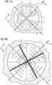
- the hatching strategy divides the top face 31 in four portions I, II, III, IV.
- the four portions I, II, III, IV are segments of, e.g., 90° angular width (i.e., quadrants) of the circular cross-section of the calibration object 21.
- the portions I, II, III, IV are aligned with respect to the illuminating light beams 25A, 27A such that respective bisectors of portions I, IV extends along the line 25B and respective bisectors of the portions II, IIII extends along the line 27B.
- the hatching strategy can be specifically selected to increase the reflection of light of the illuminating light beams 25A, 27A towards the calibration camera 23.
- the portions I, II, III, IV can be irradiated by guiding an irradiation beam along (essential) parallel scan vectors 41 or along scan vectors 41' deviating from parallel by less than 10° as schematically illustrated for portion IV in Fig. 4A .
- That hatching strategy within the calibration area 21A can be applied, for example, to any one or both of the laser beams 15A, 15B.
- the portion when irradiating a portion of the calibration area 21A using a laser beam with parallel or largely parallel scan vectors (see, e.g., scan vectors 41, 41' in X-direction in portions I and IV or scan vectors 42 in Y-direction in portions II and III in Fig. 4A ), the portion can develop a wave-shaped surface 43 with ridges 43A and recesses 43B extending in Y-direction (e.g., given in portions II and III).
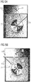
- the consequence is that light of the illuminating light beam 27B is reflected into a variety of directions (arrows 45), inter alia towards the calibration camera 23, which even can be saturated as in Fig. 6A , for example.
- an azimuthal component ⁇ can lie in the range from 45° to 90° with respect to the scan vectors 41, 42; 53A, 53B of one of the portions of the calibration area 21A (see Fig. 4A , where ⁇ equals about 90°).
- an inclination component ⁇ lies in the range from 25° to 80°, preferably in the range from 40° to 60°, with respect to a normal direction n of the layer of a powdered material 5.
- the top face 31 appears bright in an image 47 of the calibration camera 23 (see Fig. 5C white color for portions II and III with the exception of a dark line 49 that is explained below).
- Exemplary "real" images 51A, 51B taken under those two illumination conditions are shown in Figs. 6A and 6B . In each illumination condition, one sees opposite quadrants appearing bright or dark.
- the black or white quadrants of the top face 31 are related to the specific orientation of the hatching and illumination direction.
- the hatching strategy shown in Fig. 4A two different images can be taken with respectively different illumination conditions (i.e., different illumination directions) in order to improve the contrast of the calibration pattern in the images.
- Fig. 4B illustrates the first calibration pattern 37 shown in Fig. 2 with the two crossed lines 37A, 37B illustrated as hatched lines. Each line is an example of a straight-line segment.
- the crossed lines 37A, 37B are marked/created with a re-melting process just after the processing of the intermediate layer 29 was completed and without an additional layer of powdered material being coated onto the calibration area 21A.
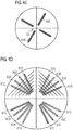
- Each of the lines 37A, 37B is created by moving the (same) laser beam 15A linearly, i.e., with linear scan vectors 44 across the calibration area 21A.
- Each of the lines 37A, 37B can be irradiated by a plurality such as eight or ten etc. parallel scan vectors 44A, 44B.
- a central region 58 of the top face 31 may be not used for the lines 37A, 37B, because in the crossing area of the lines 37A, 37B, overheating of the powder/calibration object may occur during irradiation.
- scan trajectories 44A end before the central region 58 (e.g. by blocking of the laser beam) and continuing the scan on the other side of the central region, thereby respectively forming the scan trajectories 44B.
- the image analysis sub-routine may not need the extension of the lines 37A, 37B in that central region 58, as the crossing point 37C of the lines 37A, 37B can also be determined purely on the remaining (imaged) parts of the lines 37A, 37B outside of the central region 58.
- the linear movement of the laser beam moving along the linear scan vectors 44, 44A, 44B results in a flat surface region extending in a linear shape across the wave-shaped surface 43 (at least in outer portions as discussed above).
- the line 37A extends mainly in the portions I and IV and it is oriented with respect to the scan vectors 41, 41' used for those portions under an intersecting angle ⁇ in the range from 45° to 90°, preferably under an intersecting angle ⁇ in the range from 60° to 80°, exemplarily under 70°.
- the line 37B extends mainly in the portions II and III and it is oriented with respect to the scan vectors 42 used for those portions under an intersecting angle ⁇ in the range from 45° to 90°, preferably under an intersecting angle ⁇ in the range from 60° to 80°, exemplarily under 70°.
- Fig. 4B further shows that the crossing point 37C of the lines 37A, 37B is located in the portion II and is displaced with respect to a center of the top face 31 by ⁇ X and ⁇ Y.
- the crossing point 37C is a feature of the first calibration pattern (here the cross 37) that is to be identified based on image(s) taken with the calibration camera 23.
- the surface of the intermediate layer 29A may deviate from the above described general surface features, for example, in the area in the center of the top face 31 (where all portions come together) as well as the area of the crossing of the straight-line segments.
- the image analysis sub-routine can focus on those segments within the portions that are less affected and show the expected surface features, usually the inner areas of the portions.
- the image analysis sub-routine may identify two linear line segments in portions I and IV for line 37A in image data acquired under illumination with the illuminator 25. Similarly, the image analysis sub-routine may identify linear line segments in portions II and III for line 37B in image data acquired under illumination with the illuminator 27. The image analysis sub-routine may then calculate extensions of the linear line segments and identify the position first in the image plane (i.e., in the image data) and then transfer the position onto the work surface 9B.
- Fig. 4E the top face 31 is shown additionally with a second calibration pattern, here the cross formed by lines 39A, 39B. As discussed in connection with Fig. 4B , the crossing point 39C can be identified and its position in the work surface 9B derived.
- a magnified part 59 of the central area of the top face 31 is shown in Fig. 4E .
- the scanning optics 17A, 17B can be aligned for correct guiding of the laser beams onto the work surface 9B.
- the images 51A, 51B can be processed by the image analysis sub-routine for deriving image points corresponding to the respective crossing points as described above.
- the above exemplary implementation of the calibration was based on a cylindrical shaped calibration object and a separation of the top face into for equal quadrants.
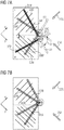
- FIG. 7A another implementation is based on a rectangular cross-section of the calibration object.
- the cross-section is divided into two rectangular portions I', II' and each of the portions is subject to a specific hatching strategy as indicated by scan vectors 53A and 53B (e.g., configurations of parallel scan vectors or essentially parallel scan vectors).
- the scan vectors 53A, 53B are oriented with respect to each other under an angle ⁇ ' that is in the range from 45° to 90°, preferably in the range from 80° to 90°.
- the calibration patterns each include linear line segments 37A', 37B'; 39A', 39B' that were generated by moving the respective irradiation beam along linear scan vectors 44'.
- the calibration patterns are V-shaped, for example, and respectively include two inclined line segments.
- the V-shaped pattern are not required to cross within the calibration area 21A, instead by extending the detected linear segments (extensions 55, 57), reference point 37C', 39C' are defined that usually lie next to the calibration object 21.
- the linear extensions 55, 57 respectively cross preferably under an angle ⁇ ' in the range from 80° to 90°.
- orientations of the linear scan vectors 44' of the first V-shaped calibration pattern are inclined with respect to orientations of the linear scan vectors 44' of the second V-shaped calibration pattern.
- the linear scan vectors 44' of the first calibration pattern or the second calibration pattern, respectively, extend within the at least two portions I', II'.
- the first reference point 37C' and the second reference point 39C' differ in position by (i.e., have an offset of) less than a threshold value.
- the threshold value is optionally equal to or smaller than a laser beam spot size (e.g., about 50 ⁇ m to 100 ⁇ m).
- the one or the other of the rectangular portions I', II' will appear bright/dark in an image acquired by the calibration camera 23.
- the straight-line segments 37A', 37B'; 39A', 39B' can appear dark in the respective lit-up rectangular portions I', II' such that an image analysis sub-routine can derive the respective image points for the reference points of the calibration patterns and initiate an alignment of the scanning optics 17A, 17B.
- the herein described concepts further allow the calibration of a scanning optics when patterns are compared generated with the same laser beam.
- the straight-line segments 61A, 61B and 63A, 63B were generated with one of the laser beams 15A, 15B, for example. This allows tuning the scanning optic and/or setting a zero-point of the scanning optic to properly displace/move the laser beam spot across the powder bed in line with a machine coordinate system.
- the herein disclosed concepts can reach accuracies in the range of 20 ⁇ m and smaller for a 50% spot size of about 30 ⁇ m.
- Fig. 8A four types of calibration measurements are performed in a repeating manner with two laser beams L and R guided by respective scanning optics.
- the sequence is set such that a specific type of a measurement is repeated every twelfth layer, for example. Accordingly in that example, crosses may be generated for:
- measurements (2) and (4) can be utilized for the zero setting of the measurement system, specifically of each scanning optics. Similar to the scale for weighing: before to weigh something, you have to press the "ZERO” button. In this way, we are “pressing the ZERO button” in every measurement (12 layers).
- the offset O can be maintained below a preset threshold value.
- Fig. 8B illustrates an exemplary development of a measurement of the offset O over a large number of layers N in an "alignment accuracy" graph.
- the calibration procedure is not performed such that at the layer S a large offset of above 50 ⁇ m is measured.
- the offset O is reduced and stabilized below an acceptable threshold value 71 such as, for example, a threshold value of 20 ⁇ m.
- lines 81A/81B - 81C/81D, lines 83A/83B - 83C/83D, lines 85A/85B - 85C/85D, and lines 87A/87B - 87C/87D respectively form a cross and define a respective crossing point for calibration.
- the lines are used to mark a calibration object selected in size depending on the resolution of the calibration camera and quality of the image analysis. As shown in Fig. 4D , still all pairs of crossing lines can be marked with an angle near to 45 deg. In particular in this case, one can reduce the laser irradiation/marking in the central region to avoid an increase of energy density beyond some threshold.
- a contrast enhancement may be achieved by specifically adapting the additive manufacturing process of the calibration layer to available illumination conditions. For example, essentially parallel scanned vectors may be used with specific portions, thereby increasing the reflection of light toward the calibration camera. In contrast, if the laser marking includes linear sections in the direction of the incident light, the calibration camera may receive less scattered light from those laser markings.
- an algorithm can process and analyze the image data to calculate an offset between laser markings produced with different laser beams (relative calibration), i.e. different laser sources guided by different scanning optics. A respective feedback can then be sent to the scanning optics in order to maintain the correct alignment of the laser beams/scanning optics.
- calibration of a single scanning optic can be done when producing the laser markings with the same laser beam.
- Fig. 9A a plurality of monitoring cameras 19, 19' are schematically shown.
- Fig. 9A corresponds to Fig. 1 with the exception of the number and position of the monitoring cameras 19, 19'.
- Fig. 9A corresponds to Fig. 1 with the exception of the number and position of the monitoring cameras 19, 19'.
- the controller 20 is data-connected to the monitoring cameras 19, 19' for receiving image data.
- Fig. 9B illustrates an image 201 of the building platform 11 as well as portions 219, 219' of the building platform 11 associated to each of the monitoring cameras 19, 19', respectively.
- the images of the monitoring cameras 19, 19' need to be combined, also referred to as image stitching or recordation of images.
- the stitching needs to be as accurate as possible if the combined image 201 is used for an analysis of, e.g., the powder bed surface provided on the building platform 11.
- the surface of the powder bed section does not have specific characteristic features that could be used for image analysis due to the diffuse scattering of the powder 5.
- the simple conventional procedures mentioned above for the combination of images based on specific features cannot be applied.
- the in the following described stitching procedure can enable the composition of a combined image even if no recorded high-contrast features are available or lie within an overlap region 221 indicated in Fig. 9B .
- the above calibration analysis may be performed on a stitched image, if, e.g., multiple calibration objects are created at different regions of the powder bed because generally the positioning of multiple calibration objects may depend on the specific manufacturing job and the areas available for the calibration objects.
- the task of the image analysis is in the specific example of the images of Figs 10A and 10B to derive information on the movement of the camera, i.e., direction and length of the shift of the imaged areas with respect to each other, or generally the relative shift a group of essentially identical image data within the two images 225A, 225B.
- a search window of for example, 200 x 200 pixels is selected in a region that falls within each of the two images 225A, 225B.
- cross-correlation values were calculated based on the above formula.
- Exemplary graphs of the correlation values Corr for relative shifts in a X-direction (graph 229A) and a Y-direction (graph 229B) are indicated in Fig. 11A .
- the graphs are selected to pass through a highest correlation value Corr_max (see Fig. 11B )
- a combined image 335 is based - as superposed image 333 - on the correlation value Corr_max.
- the combined image 335 includes at each pixel only a contribution from one of the images. In the combined image 335, one cannot see a transition line or break that would indicate a stitching.
- FIG. 13 another example of a superposed image 337 is shown, indicating that the algorithm also provides for good stitching results of a corner-shaped laser mark 337A.
Landscapes
- Engineering & Computer Science (AREA)
- Chemical & Material Sciences (AREA)
- Materials Engineering (AREA)
- Manufacturing & Machinery (AREA)
- Toxicology (AREA)
- Health & Medical Sciences (AREA)
- Physics & Mathematics (AREA)
- Optics & Photonics (AREA)
- Automation & Control Theory (AREA)
- General Health & Medical Sciences (AREA)
- Mechanical Engineering (AREA)
- Analytical Chemistry (AREA)
- Plasma & Fusion (AREA)
- Microelectronics & Electronic Packaging (AREA)
- Powder Metallurgy (AREA)
Abstract
Description
- The present disclosure relates generally to an additive manufacturing device with multi-beam irradiation using multiple scanning optics. Moreover, the present disclosure relates to a method of automated alignment of scanning optics of an additive manufacturing device.
- In additive manufacturing such as selective laser sintering or selective laser melting, a powdered material such as a metal or ceramic powder is irradiated with electromagnetic radiation. Successively, thin layers of powder are provided within a chamber on a building platform to form three-dimensional objects by irradiating the respective layers of powder with an irradiation beam such as a laser beam. Respective devices are referred to as additive manufacturing devices, 3D-printing systems, selective laser sintering machines, or selective laser melting machines and the like. For the operation of such a device, it is referred to
EP 2 732 890 A2 , for example. - For increasing the speed of the building process or the size of an object that can be built, multiple irradiation beams can be used within one additive manufacturing device and for one building platform. For example, in an additive manufacturing device using multiple laser beams, the alignment of the coordinate systems of the underlying scanning optics that each direct a laser beam is to be maintained during the complete building process in order to guarantee a proper alignment of the scanned laser trajectories in the layer plane. In particular, an accuracy of the alignment between different laser beams/scanning optics is preferred to be in the range of 50 % of a laser beam diameter and less.
- With respect to calibrating an irradiation system of an apparatus for producing a three-dimensional workpiece,
WO 2019/158394 A1 discloses irradiating a first irradiation beam and a second irradiation beam onto an irradiation plane such that operating axes of irradiation patterns traverse each other. A calibration is performed by determining a position of an intersection point between the irradiation patterns of the first irradiation beam and the second irradiation beam. Moreover,EP 2 983 898 A1 discloses determining a relative positional deviation between a first and second test pattern generated by two laser beams in a target within a powder layer for calibrating respective scanners. Furthermore,WO 2019/161886 A1 discloses building a first test structure by a first radiation beam and a second test structure by a second radiation beam and determining an offset between the two test structures. - A proper alignment of multiple laser scanners/scanning optics is in particular essential if a single object is manufactured with multiple irradiation beams. It is noted that in particular for large parts and temperature fluctuations, thermal effects onto the various components and the built part may require continuous calibration of the laser scanners during the manufacturing.
- Therefore, it is in particular an object of the present disclosure to provide a calibration procedure that can easily be performed in an automated manner, can be implemented in a simple manner also in existing additive manufacturing devices, and can be performed preferably throughout the manufacturing process.
- In general, the present disclosure is directed, at least in part, to improving or overcoming one or more aspects of the prior systems, and in particular to provide an efficient approach for calibrating/aligning coordinate systems associated to respective irradiation beams in a multi-beam additive manufacturing device.
- Thus, the present disclosure is directed, at least in part, to improving or overcoming one or more aspects of prior systems.
- Some of the objects may be achieved by a method of automated alignment of a first scanning optic and a second scanning optic as recited in
claim 1 and device for additive manufacturing of three-dimensional objects as recited in claim 15. Further aspects and developments are given in the dependent claims. - In a first aspect, the present disclosure is directed to a method of automated alignment of a first scanning optic associated to a first irradiation beam and a second scanning optic associated to a second irradiation beam during additive manufacturing of a target object. The method comprises the steps:
- irradiating an object area of a layer of a powdered material provided on a building platform with at least one of the first irradiation beam or the second irradiation beam, wherein the object area is associated with a cross-section of the target object;
- irradiating a calibration area of the layer of the powdered material with at least one of the first irradiation beam and the second irradiation beam, where the calibration area is associated with a cross-section of a calibration object, thereby forming an intermediate top face of the calibration object;
- guiding the first irradiation beam with the first scanning optic over the intermediate top face and thereby melting a first calibration pattern having a first geometrical feature into the intermediate top face;
- guiding the second irradiation beam with the second scanning optic over the intermediate top face and thereby melting a second calibration pat-tern having a second geometrical feature into the intermediate top face;
- acquiring at least one image of the intermediate top face having the first calibration pattern and the second calibration pattern thereon;
- using the at least one image, identifying image points related to the first geometrical feature and the second geometrical feature;
- from the image points, deriving a spatial offset between positions of the first geometrical feature and the second geometrical feature within the layer of the powdered material; and
- aligning at least one of the first scanning optic or the second scanning optic under consideration of the spatial offset.
- In another aspect, a device for additive manufacturing of three-dimensional objects from powdered material comprises:
- an object forming chamber with a work surface and a building plat-form, wherein the building platform is adjustable in a vertical position with respect to a building platform opening for layer-by-layer manufacturing of a three-dimensional object and a calibration object on the building platform;
- a calibration camera configured to acquire an image of at least a calibration section of the work surface that is associated to the calibration object; and
- an irradiation system including at least two scanning optics configured for guiding respective irradiation beams onto a layer of powdered material distributed on top of the building platform; and
- a controller with at least one microprocessor and at least one storage device storing instructions that are operable, when executed by the at least one micro-processor, to cause the device to control the vertical position of the building plat-form, receive image data from the calibration camera, control the irradiation system, and execute a method as described above.
- Further embodiments of the above aspects, are disclosed in the dependent claims, which are incorporated herein by reference.
- For example, in some embodiments of the method, when forming the intermediate top face of the calibration object, the calibration area can be irradiated in a plurality of portions, wherein at least one of
- at least of the plurality of portions is manufactured to have a wave-shaped surface, and
- In some embodiments, the method may further comprise the step:
- directing an illuminating light beam onto the intermediate top face having the first calibration pattern and the second calibration pattern, wherein an incident direction of the illuminating light beam has
- an azimuthal component in the range from 45° to 90° with respect to the scan vectors of one of the portions of the calibration area and
- an inclination component in the range from 25° to 80°, preferably in the range from 40° to 60°, with respect to a normal direction of the layer of a powdered material, and wherein
- the at least one image of the intermediate top face with the first calibration pattern and the second calibration pattern is acquired while the illuminating light beam is directed onto the intermediate top face.
- In some embodiments, for each orientation of parallel scan vectors, an illuminating light beam is directed onto the intermediate top face and an image is acquired, and the method may further comprise:
- generating a superposition of the images acquired for each configuration of scan vectors, and
- the image points of the first feature and the second feature are identified based on the superposition of the images.
- In some embodiments, the method may further comprise the step:
- for each of the first calibration pattern and the second calibration pattern, melting a plurality of straight-line segments with a flat surface region, wherein
- for each of the first calibration pattern and the second calibration pattern, at least one of the plurality of straight-line segments extends in the first portion and is oriented with respect to the scan vectors used for the first portion under a first intersecting angle in the range from 45° to 90°, preferably under a first intersecting angle in the range from 60° to 90° or from 60° to 80°.
- In some embodiments, a second portion of the plurality of portions can be irradiated by guiding at least one of the first irradiation beam and the second irradiation beam along scan vectors that run parallel to each other or deviate from running parallel by less than 10°, and
wherein the scan vectors of the second portion differ in orientation with respect to the scan vectors of the first portion by an angle in the range from 45° to 90°, preferably by an angle in the range from 80° to 90°. - In some embodiments, for each of the first calibration pattern and the second calibration pattern, at least one of the plurality of straight-line segments can extend in the second portion and is oriented with respect to the scan vectors used for the second portion under an intersecting angle in the range from 45° to 90°, preferably under an intersecting angle in the range from 60° to 90° or from 60° to 80°.
- In some embodiments of the method, the calibration area may include two pairs of opposing portions, each pair of portions is irradiated by guiding at least one of the first irradiation beam and the second irradiation beam along scan vectors, wherein the scan vectors of the two pairs are oriented with respect to each other under an angle in the range from 45° to 90°, preferably under an angle in the range from 80° to 90°,
the first calibration pattern can include a pair of straight-line segments that cross in a first reference point defining the first geometrical feature, and each of the straight-line segments can extend sufficiently long enough within one of the pairs of opposing portions of the calibration area that an orientation of a straight-line segment can be estimated (e.g., for small calibration objects, e.g. in a range from 20% up),
the second calibration pattern can include a pair of straight-line segments that cross in a second reference point defining the second geometrical feature and each of the straight-line segments extends sufficiently long enough within one of the pairs of opposing portions of the calibration area that an orientation of a straight-line segment can be estimated (e.g., for small calibration objects, e.g. in a range from 20% up),
the spatial offset is the difference in positions of the first reference point and the second reference point,
the straight-line segments are respectively generated by moving the respective irradiation beam along linear scan vectors, wherein orientations of the linear scan vectors of the first calibration pattern are inclined with respect to orientations of the linear scan vectors of the second calibration pattern, and preferably the linear scan vectors of the first calibration pattern and the linear scan vectors of the second calibration pattern respectively cross under an angle in the range from 80° to 90°. - In an exemplary embodiment, one may create a length of a line segment to be, e.g., 8 mm on a cylindrical column of 36 mm diameter.
- In some embodiments of the method, the calibration area can include at least two portions and the at least two portions are irradiated by guiding at least one of the first irradiation beam and the second irradiation beam along scan vectors, wherein the scan vectors in one of the at least two portions are oriented with respect the scan vectors in another one of the at least two portions under an angle in the range from 45° to 90°, preferably under an angle in the range from 80° to 90°, and
the first calibration pattern and the second calibration pattern can each include straight-line segments generated by guiding the respective irradiation beam along linear scan vectors, wherein orientations of the linear scan vectors of the first calibration pattern are inclined with respect to orientations of the linear scan vectors of the second calibration pattern, and
the straight-line segments can be associated to linear extensions that respectively cross in a first reference point defining the first geometrical feature or a second reference point defining the second geometrical feature, wherein the linear extensions respectively cross for the first calibration pattern and the second calibration pattern preferably under an angle in the range from 80° to 90°. - In some embodiments of the method, the first calibration pattern and the second calibration pattern can each include straight-line segments and the method may further comprise:
- in the at least one image, deriving straight lines that extend through the images of the straight-line segments and identifying the image points at a crossing of the straight lines, and
- deriving the spatial offset in the layer of the powdered material from the distance between the image points in the image.
- In some embodiments of the method, aligning the first scanning optic or the second scanning optic can include setting an optical beam path through a respective scanning optic or a zero-point associated to the respective scanning optic for guiding the laser beams across the powder bed in line with a machine coordinate system; and/or
a first layer associated to the calibration object can be attached to the building platform and preferably the calibration object can be positioned at a border region of the building platform. In addition or alternatively, for a plurality of layers of the powdered material applied for the manufacturing of the target object, the first calibration pattern and the second calibration pattern can be melted into respective intermediate top faces of the calibration object to repeatedly perform the alignment of the first scanning optic and the second scanning optic throughout the additive manufacturing. - In some embodiments of the device, the device may further comprise:
- an illuminator positioned to direct an illuminating light beam onto the calibration section, and
- wherein the at least one storage device can further store instructions that are operable, when executed by the at least one microprocessor, to activate the illuminator to illuminate the calibration section, and control the calibration camera to acquire an image while the illuminator is activated.
- In some embodiments of the device, the illuminator can be configured to emit a light beam onto an intermediate top face of the calibration object under an incidence direction in the range from 25° to 80°, preferably in the range from 40° to 60°, with respect to a normal direction of a layer of a powdered material.
- In some embodiments of the device, at least one of
the calibration camera can be positioned vertically above the calibration section,
the calibration camera can be configured to image the complete work surface,
the calibration section can be located at a border region of the building platform opening, or
the device can further comprises a powder system configured for distributing powdered material across the work surface with a powder depositing tool to provide the powdered material layer by layer on the building platform during the additive manufacturing. The alignment of the first and second scanning optics preferably such that, when repeating the calibration procedure in a subsequent layer of powdered material, the first feature/reference point and the second feature/reference point differ in position by less than a threshold value. The threshold value may optionally be wet to be equal to or smaller than a laser beam spot size, e.g. 50 % of the laser beam spot size on the layer of powdered material. - Another aspect relates to a computer program product comprising instructions to cause the herein disclosed device for additive manufacturing to execute the steps of the method of automated alignment.
- In some embodiments, when reading an additive manufacturing instruction protocol that includes irradiation instructions for manufacturing the target object into a control unit, the control unit adds irradiation instructions for manufacturing the calibration object layer by layer and calibration instructions that perform the image analysis and the offset determination.
- Another aspect relates to a method for marking and analyzing an intermediate layer in particular for optical calibration of one or more scanning optics. The method includes:
- generating an intermediate layer to have a diffuse scattering and/or rough surface, wherein the intermediate layer is generated by additive manufacturing based on a first irradiation strategy;
- marking the intermediate layer with a laser beam used for the additive manufacturing at the top face based on a second irradiation strategy;
- illuminating the top face with a light beam at an angle generating increased scattering; and
- taking an image of the top face, in which an imaging signal/detected light is increased a region generated with the first irradiation strategy only, e.g. for the diffuse scattering and/or rough surface, with respect to an imaging signal for the region marked with the second irradiation strategy.
- An advantage of the herein disclosed calibration is that any part/object can be produced with multiple laser beams without any lack of quality due to a misalignment of laser beams, specifically a misalignment of the scanning optics.
- Other features and aspects of this disclosure will be apparent from the following description and the accompanying drawings.
- The accompanying drawings, which are incorporated herein and constitute a part of the specification, illustrate exemplary embodiments of the disclosure and, together with the description, serve to explain the principles of the disclosure. In the drawings:
-
Fig. 1 is a schematic view of an exemplary additive manufacturing device; -
Fig. 2 is a schematic image of a top-face of a calibration structure having two pairs of crossing lines as calibration patterns thereon; -
Fig. 3 a flowchart illustrating an exemplary calibration procedure during additive manufacturing; -
Fig. 4A is a schematic illustration of an exemplary two-beam scan procedure used for preparing an intermediate calibration layer with varying reflective properties in different portions of a respective intermediate top face; -
Fig. 4B is a schematic illustration of a first pair of crossing lines applied with a first laser beam onto the calibration layer prepared as shown inFig. 3A ; -
Fig. 4C is a schematic illustration of the use of scan vectors for generating crossing lines; -
Fig. 4D is a schematic illustration of calibrating a plurality of scanning optics; -
Fig. 4E is a schematic illustration of a second pair of crossing lines applied with a second laser beam onto the calibration layer as shown inFig. 3B ; -
Fig. 5A is a schematic cut-view of the calibration layer through portions II or III as indicated inFig. 3A for illustrating partial redirection of light of an illuminator onto a calibration camera; -
Fig. 5B is a schematic cut-view of a calibration layer along a line of a calibration pattern for illustrating specular reflection of light of the illuminator to pass by the camera; -
Figs. 6A and 6B show images of an intermediate calibration layer with two pairs of crossing scan lines being illuminated with respective illuminators from the side; -
Figs. 7A and 7B are schematic illustrations of an alternative configuration of a calibration object and a further calibration procedure, respectively; -
Figs. 8A und 8B are schematic illustrations repeating calibrating and readjusting irradiation systems during additive manufacturing and the resulting offset reduction; -
Figs. 9A and 9B are a schematic view of an exemplary additive manufacturing device with two powder bed cameras and an image of a powder bed, respectively; -
Figs. 10A and 10B are two images shifted with respect to each other; -
Figs. 11A and 11B are a plot with correlation curves and respective a correlation map, respectively for the images ofFigs. 10A and 10B ; -
Figs. 12A and 12B are an overlaid image and a resulting composite image, respectively; and -
Fig. 13 is an overlaid image, where a stitching applies over a corner of the images. - The following is a detailed description of exemplary embodiments of the present disclosure. The exemplary embodiments described therein and illustrated in the drawings are intended to teach the principles of the present disclosure, enabling those of ordinary skill in the art to implement and use the present disclosure in many different environments and for many different applications. Therefore, the exemplary embodiments are not intended to be, and should not be considered as, a limiting description of the scope of patent protection. Rather, the scope of patent protection shall be defined by the appended claims.
- The disclosure is based in part on the realization that proper alignment of a multi-beam irradiation system can be ensured by growing a calibration structure additionally during the additive manufacturing process (i.e., at the same time of growing the 3D-object and preferably separate from the same). The calibration structure includes specific intermediate calibration layers that are used for analyzing the calibration status of the multi-beam irradiation system. The intermediate calibration layers may include specific calibration patterns each generated with one of the irradiation systems and each defining a reference point for that irradiation system. Moreover, it was realized that detection of calibration patterns can be improved by forming the same on a specifically prepared intermediate calibration layer that improves the image acquisition, specifically the contrast, under respectively set illumination conditions.
- In the following, an additive manufacturing device is described in connection with
Fig. 1 . An exemplary implementation of the herein proposed concept for calibrating multiple radiation sources is described for multi-laser beam based additive manufacturing in connection withFigs. 2 to 6B . In connection withFigs. 7A and 7B , an alternative geometrical implementation as well as a further use of the herein described imaging concepts is described. Exemplary implementations of the concept for calibrating multiple scanning optics into an additive manufacturing process is finally described in connection withFigs. 8A and 8B . -
Fig. 1 illustrates schematically adevice 1 for additive manufacturing of three-dimensional objects 3 (herein also referred to as target objects) from apowdered material 5.Device 1 includes an object forming chamber 7 within a housing that provides for the required environment of the manufacturing process.Fig.1 schematically shows atop cover 9A and awork surface 9B delimiting the chamber 7. The chamber 7 is further delimited by sidewalls and a back wall (not shown). A front door (also not shown) may provide access to the chamber 7. - The additive manufacturing process is performed on the
work surface 9B, specifically on abuilding platform 11. Thebuilding platform 11 can be lowered along direction Z to successively provide new layers of powdered material for a layer-by-layer manufacturing process. The powdered material can be evenly spread onto thebuilding platform 11 by apowder depositing tool 13 to form a powder bed. Thepowder depositing tool 13 extends in direction Y and can be moved in direction X across thework surface 9B to a building platform opening 11A in which the powder bed is formed on top of thebuilding platform 11. Thus, the layers ofpowdered material 5 extend within a layer plane, here the X-Y -plane. - The powder bed is prepared for being irradiated with laser radiation to initiate a powder melting process by absorption of the laser radiation and followed by a solidification process within the respective cross-sections of the
objects 3. - For that purpose, the powdered material is irradiated with a plurality of
laser beams laser beam scanning optic work surface 9B. Thescanning optic scanning optic scanning optic - As the herein disclosed concepts are applicable also to more than two laser beams, an exemplary
third scanning optic 17C is indicated inFig. 1 in dashed lines. The laser source(s) such as a fiber or a disc laser may be provided on top of thetop cover 9A or may be positioned differently such that the laser beams need to be guided, e.g., by light fibers to thescanning optics - The manufacturing process can be monitored with a
monitoring camera 19 that is, for example, positioned centrally above thebuilding platform 11. The monitoringcamera 19 can have a resolution of about 90 µm per pixel and may be configured for a low distortion of the acquired images of thework surface 9B. Providing a dedicated camera for monitoring the generative growing can offer an improved performance. However, as explained below, various tasks can be performed by a single camera, e.g., the monitoringcamera 19 may also be used for the calibration procedure. - Each of the
laser beams objects 3 as defined in a CAD/CAM control file (also referred herein to as additive manufacturing instruction protocol) of a specific manufacturing job. - For controlling the additive manufacturing, the
device 1 includes acontroller 20 with at least onemicroprocessor 20A and at least onestorage device 20B. The at least onestorage device 20B stores instructions that are operable, when executed by the at least onemicroprocessor 20A, to cause thedevice 1 to control the vertical position of thebuilding platform 11, receive image data from cameras, and control the irradiation system (e.g., setting the laser parameters and guiding the laser beams over the powder bed. For example, the CAD/CAM control file can be loaded into the at least onestorage device 20B to provide the instructions to themicroprocessor 20A. - The CAD/CAM control file includes instructions that, when executed by the at least one
microprocessor 20A of thecontroller 20, define which laser beam is directed onto which portion of the cross-section. For that purpose, thecontroller 20 is, for example, connected to thescanning optics different laser beams different laser beams - In addition, the CAD/CAM control file can include parameter values for the laser system, the lowering of the
building platform 11, thepowder depositing tool 13 etc. - For the herein disclosed calibration, the CAD/CAM file is extended with instructions to form a
calibration object 21 at the same time as forming theobjects 3. As shown inFig. 1 , thecalibration object 21 is, for example, cylinder shaped with a diameter of, for example, about 8 mm to 10 mm. Thecalibration object 21 is located close to the border of thebuilding platform 11, thereby taking only a limited space for the arrangement ofobjects 3 to be build. - For the calibration, the
device 1 further includes acalibration camera 23 and twoilluminators work surface 9B and in particular a top layer of thecalibration object 21. Schematically, two illuminatinglight beams Fig.1 . Theilluminators work surface 9B, specifically an intermediate top face of thecalibration object 21. - The herein proposed calibration can be performed every couple layers, i.e., an intermediate layer, such as every fourth layer. The calibration may also be initiated depending on need.
Fig. 1 shows a plurality of intermediatedlayers 29 schematically in thecalibration object 21.Intermediate layers 29 were used for calibration of the offset, for example. "Intermediate" relates here to the fact that the layers are used for calibration but then are grown over. A first intermediate layer 29_1 may be attached to thebuilding platform 11 and allow a first calibration. Anintermediate layer 29A is "currently" processed inFig. 1 and to be used for the calibration. - For the
intermediate layer 29A,Fig. 1 shows an illustration of a circular (intermediate)top face 31 of the cylinder-shapedcalibration object 21. An image of thetop face 31 can be acquired with thecalibration camera 23. In reference to the following discussion of the herein disclosed concepts of calibration, laser generated calibration patterns 33 are schematically indicated on thetop face 31 shown. - Specifically, as shown in more detail in
Fig. 2 , a cross-like structure (two pairs of linear lines crossing each other or linear lines associated to an identified structure) can be created with eachlaser beam calibration object 21 by a re-melting process, i.e., after the intermediate layer was processed. - The
calibration camera 23 takes pictures oftop face 31 with the marked cross-like structures. Thecontroller 20 is data-connected to the calibration camera 23 (as well as optionally the monitoring camera 19) for receiving image data. Similarly, thecontroller 20 is data-connected to the twoilluminators exemplary data lines 20C inFig. 1 .) - The calibration procedure uses, for example, a calibration algorithm that can be executed in the
microprocessor 20A of thecontroller 20. The calibration algorithm can include an image analysis sub-routine and a calibration-setting sub-routine. - The image analysis sub-routine is programmed to identify a reference point for each cross such as a center or crossing point, and calculate an offset between the two crosses. The calibration-setting sub-routine is programmed to derive an offset compensation value as a control parameter to one or both of the
scanning optics laser beams - For the calibration, a beam spot size of each of the
laser beams work surface 9B in the area of the calibration object 21 - can be, for example, in the range from 50 µm up to 100 µm. Thecalibration camera 23 can have, for example, a resolution of 25 µm per pixel and may be dedicated specifically to the calibration procedure. While the configuration ofdevice 1 shown inFig. 1 has themonitoring camera 19 located above a center of the building platform 11 (also referred to as substrate) and thecalibration camera 23 above a border area of the substrate, in some embodiments themonitoring camera 19 may also be used for the calibration procedure. -
Fig. 2 shows asuperimposed image 35 of thetop face 31. Thesuperimposed image 35 is the result of two images acquired based on the procedure explained in connection withFigs. 3A to 3C . Specifically, two images were superposed onto each other that were imaged for different illumination settings. - The
superimposed image 35 shows twocrosses 37, 39 (calibration patterns) formed of respective pairs of orthogonal straight-line segments (short straight lines) 37A, 37B and 39A, 39B (the lines are line shaped surface areas that were created by re-melting the top face 31). Each of the illumination settings increases the contrast for straight lines extending essentially along the respective illumination direction, such aslines lines - For each of the
crosses crossing point work surface 9B. For example, the crossing points 37C, 39C should coincide for perfect alignment. At least an offset (spatial distance) between the crossing points 37C, 39C should be less than a preset value such as less than, e.g., 50 % of a beam spot size. When determining an offset associated to the irradiation system of thedevice 1, specifically thescanning optics crosses work surface 9B, which is related to the offset of thescanning optics - As mentioned above, a re-melting process can be used to increase the viewability of the
crosses calibration camera 23. -
Fig. 3 shows a flowchart for an exemplary calibration procedure. The re-melting process requires as afirst step 101 irradiating acalibration area 21A of the layer of thepowdered material 5 with at least one of the first irradiation beam (laser beam 15A inFig. 1 ) and the second irradiation beam (laser beam 15B inFig. 1 ) and forming an intermediatetop face 31 of thecalibration object 21; thecalibration area 21A is associated with a cross-section of thecalibration object 21 in the X-Y-plane (seeFig. 1 ). - As said, the formation of the
intermediate layer 29A of thecalibration object 21 takes place during the layer-wise manufacturing of theobjects 3, e.g., while or shortly before or after irradiating (step 103 inFig. 2 ) anobject area 3A of the layer of powdered material 5 (seeFig. 1 ) with at least one of the first irradiation beam and the second irradiation beam; theobject area 3A is associated with a cross-section of the (target)object 3 in the X-Y-layer plane. In other words,steps powdered material 5. - It is noted that in principle the one
intermediate layer 29A of thecalibration object 21 processed instep 101 may include several layers of one of theobjects 3, if, e.g., thinner layers are required. I.e., step 103 may be performed several times before a sufficient thickness of a powder layer is accumulated for the calibration procedure. In principle this can also be the case vice versa. - Once the intermediate
top face 31 is formed, instep 105A, the first irradiation beam is guided with thefirst scanning optic 17A over thecalibration area 21A. Thereby, the first irradiation beam melts a first calibration pattern having a first geometrical feature (e.g., thecross 37 has a crossing point of the lines) into thetop face 31. Similarly, instep 105B, the second irradiation beam is guided with thesecond scanning optic 17B over thecalibration area 21A. Thereby, the second irradiation beam melts a second calibration pattern having a second geometrical feature (e.g., thecross 39 has a crossing point of the lines) into thetop face 31.Steps - Now, having re-melted the two calibration patterns on the
intermediate calibration layer 29A, thecalibration camera 23 takes one or more images from the top face 31 (step 107). The one or more images are processed by the image analysis sub-routine. The image analysis sub-routine identifies an image point (e.g., crossingpoint 37C inFig. 2 ) related the first feature of the first calibration pattern and an image point (e.g., crossingpoint 39C inFig. 2 ) of the second feature of the second calibration pattern (step 109). - Based on the image points (corresponding to the crossing points 37C, 39C), generally from an image data-based offset, the calibration-setting sub-routine derives in step 111 a spatial offset defined in the layer of the powdered material 5 (i.e., at the level of the
work surface 9B). Thus, the offset is defined between X-Y-positions in thework surface 9B that correspond to the first feature and the second feature that were identified in the acquired images. Using the information on the derived spatial offset O, at least one of thefirst scanning optic 17A or thesecond scanning optic 17B is set to reduce the spatial offset, i.e., to increase the alignment of thelaser beams - As further illustrated in
Fig. 3 , a plurality of layers may be processed for theobjects 3 with those "calibrated" settings of the scanning optics (additional steps 103). This growing is accompanied by growing also the calibration object 21 (additional layer forming steps 101' are performed only). Then, the calibration can be initiated again (step 101) followed withsteps - To further increase the viewability of the
crosses calibration camera 23, the re-melting process can be adapted to affect the reflective properties of the intermediate top face 31 (here those areas that are not re-melted insteps intermediate layer 29A (the top face 31), it is proposed to apply a specific hatching strategy to the powder bed within the calibratingarea 21A that increases an image contrast for specific directions of illumination. The underlying concepts are described in connection withFigs. 4A to Fig. 6B . -
Fig. 4A shows a schematic top view onto the top face 31 (and the surrounding powder bed/powdered material 5). The illuminatinglight beams top face 31 from orthogonal directions (or at least almost orthogonal directions, e.g., under 60° to 90°). Projections of the central rays of the incident illuminatinglight beams work surface 9B are shown inFigs. 4A to 4E bylines line 25B and theline 27B run orthogonal to each other in the plane of thework surface 9B). - The hatching strategy divides the
top face 31 in four portions I, II, III, IV. The four portions I, II, III, IV are segments of, e.g., 90° angular width (i.e., quadrants) of the circular cross-section of thecalibration object 21. The portions I, II, III, IV are aligned with respect to the illuminatinglight beams line 25B and respective bisectors of the portions II, IIII extends along theline 27B. - In each of the four portions I, II, III, IV, the hatching strategy can be specifically selected to increase the reflection of light of the illuminating
light beams calibration camera 23. For example, the portions I, II, III, IV can be irradiated by guiding an irradiation beam along (essential)parallel scan vectors 41 or along scan vectors 41' deviating from parallel by less than 10° as schematically illustrated for portion IV inFig. 4A . That hatching strategy within thecalibration area 21A can be applied, for example, to any one or both of thelaser beams - As illustrated in
Fig. 5A , when irradiating a portion of thecalibration area 21A using a laser beam with parallel or largely parallel scan vectors (see, e.g., scanvectors 41, 41' in X-direction in portions I and IV or scanvectors 42 in Y-direction in portions II and III inFig. 4A ), the portion can develop a wave-shapedsurface 43 withridges 43A and recesses 43B extending in Y-direction (e.g., given in portions II and III). The consequence is that light of the illuminatinglight beam 27B is reflected into a variety of directions (arrows 45), inter alia towards thecalibration camera 23, which even can be saturated as inFig. 6A , for example. This is in particular the case if a specific azimuthal direction of incidence is selected, e.g. the light beam'sprojection line 27B extends along the X-direction. Generally, an azimuthal component ϑ can lie in the range from 45° to 90° with respect to thescan vectors calibration area 21A (seeFig. 4A , where ϑ equals about 90°). Moreover, an inclination component ϕ lies in the range from 25° to 80°, preferably in the range from 40° to 60°, with respect to a normal direction n of the layer of apowdered material 5. - Under such an illumination condition, the
top face 31 appears bright in animage 47 of the calibration camera 23 (seeFig. 5C white color for portions II and III with the exception of adark line 49 that is explained below). - Referring back to
Fig. 4A , in an image taken by thecalibration camera 23 when theilluminator 27 is activated, the portions II and III appear bright, while the portions I and IV appear dark. In contrast, when theilluminator 25 is activated, the portions I and IV appear bright and the portions II and III appear dark. - Exemplary "real"
images Figs. 6A and 6B . In each illumination condition, one sees opposite quadrants appearing bright or dark. - In other words, the black or white quadrants of the
top face 31 are related to the specific orientation of the hatching and illumination direction. With the hatching strategy shown inFig. 4A , two different images can be taken with respectively different illumination conditions (i.e., different illumination directions) in order to improve the contrast of the calibration pattern in the images. -
Fig. 4B illustrates thefirst calibration pattern 37 shown inFig. 2 with the two crossedlines lines intermediate layer 29 was completed and without an additional layer of powdered material being coated onto thecalibration area 21A. Each of thelines laser beam 15A linearly, i.e., withlinear scan vectors 44 across thecalibration area 21A. - Referring to
Fig. 4C , the use of scan vectors is further illustrated. Each of thelines parallel scan vectors central region 58 of thetop face 31 may be not used for thelines lines trajectories 44A end before the central region 58 (e.g. by blocking of the laser beam) and continuing the scan on the other side of the central region, thereby respectively forming thescan trajectories 44B. It is noted that, in some embodiments, the image analysis sub-routine may not need the extension of thelines central region 58, as thecrossing point 37C of thelines lines central region 58. - In any case, the linear movement of the laser beam moving along the
linear scan vectors - As illustrated in
Fig. 5B , when irradiating aflat surface region 46 as generated essentially for the calibration patterns, incident light of the illuminatinglight beam 27A is specular reflected. A specular reflectedlight beam 27A' is not received by thecalibration camera 23 as long as thecalibration camera 23 is not positioned in the area of the specular reflectedlight beam 27A'. Such a situation can be generated for line segments of the crossedlines Fig. 4B , the light beam'sprojection line 27B as well as theline 37B extend along the X-direction. Under such an illumination condition, thedark line 49 appears in theimage 47 acquired by thecalibration camera 23 as shown exemplarily for the straight-line segment extending through the portions II and III inFig. 5C . - As shown in
Fig. 4B , theline 37A extends mainly in the portions I and IV and it is oriented with respect to thescan vectors 41, 41' used for those portions under an intersecting angle αin the range from 45° to 90°, preferably under an intersecting angle α in the range from 60° to 80°, exemplarily under 70°. Similarly, theline 37B extends mainly in the portions II and III and it is oriented with respect to thescan vectors 42 used for those portions under an intersecting angle β in the range from 45° to 90°, preferably under an intersecting angle β in the range from 60° to 80°, exemplarily under 70°. -
Fig. 4B further shows that thecrossing point 37C of thelines top face 31 by ΔX and ΔY. Thecrossing point 37C is a feature of the first calibration pattern (here the cross 37) that is to be identified based on image(s) taken with thecalibration camera 23. - It is noted that the surface of the
intermediate layer 29A may deviate from the above described general surface features, for example, in the area in the center of the top face 31 (where all portions come together) as well as the area of the crossing of the straight-line segments. Thus, the image analysis sub-routine can focus on those segments within the portions that are less affected and show the expected surface features, usually the inner areas of the portions. - Regarding the identification of the position of the
crossing point 37C, the image analysis sub-routine may identify two linear line segments in portions I and IV forline 37A in image data acquired under illumination with theilluminator 25. Similarly, the image analysis sub-routine may identify linear line segments in portions II and III forline 37B in image data acquired under illumination with theilluminator 27. The image analysis sub-routine may then calculate extensions of the linear line segments and identify the position first in the image plane (i.e., in the image data) and then transfer the position onto thework surface 9B. - In
Fig. 4E , thetop face 31 is shown additionally with a second calibration pattern, here the cross formed bylines Fig. 4B , thecrossing point 39C can be identified and its position in thework surface 9B derived. - In addition, a magnified
part 59 of the central area of thetop face 31 is shown inFig. 4E . One can see a spatial offset O between thecrossing point 37C and thecrossing point 39C. Based thereon thescanning optics work surface 9B. - Referring again to the
images calibration section 21A shown inFigs. 6A and 6B , one sees in each case two dark lines extending through the lit-up portions II, III and I, IV, respectively. The dark lines relate to thelines lines - It is noted that in each case also a lit-up line in the dark quadrants can be seen due to curvature present across the otherwise flat surfaces, resulting in partial redirecting of the light beam towards the
calibration camera 23. - For example, the
images - The above exemplary implementation of the calibration was based on a cylindrical shaped calibration object and a separation of the top face into for equal quadrants.
- However, the concepts can be applied to a variety of geometries.
- Referring to
Fig. 7A , another implementation is based on a rectangular cross-section of the calibration object. The cross-section is divided into two rectangular portions I', II' and each of the portions is subject to a specific hatching strategy as indicated byscan vectors scan vectors - The calibration patterns each include
linear line segments 37A', 37B'; 39A', 39B' that were generated by moving the respective irradiation beam along linear scan vectors 44'. InFig. 7A , the calibration patterns are V-shaped, for example, and respectively include two inclined line segments. The V-shaped pattern are not required to cross within thecalibration area 21A, instead by extending the detected linear segments (extensions 55, 57),reference point 37C', 39C' are defined that usually lie next to thecalibration object 21. Thelinear extensions - In a status of alignment of the first and
second scanning optics first reference point 37C' and thesecond reference point 39C' differ in position by (i.e., have an offset of) less than a threshold value. The threshold value is optionally equal to or smaller than a laser beam spot size (e.g., about 50 µm to 100 µm). - For enhancing the contrast, applying again specific illumination directions with respect to the hatching strategy/orientation of the scan vectors, the one or the other of the rectangular portions I', II' will appear bright/dark in an image acquired by the
calibration camera 23. Similarly, the straight-line segments 37A', 37B'; 39A', 39B' can appear dark in the respective lit-up rectangular portions I', II' such that an image analysis sub-routine can derive the respective image points for the reference points of the calibration patterns and initiate an alignment of thescanning optics - Referring to
Fig. 7B , in addition to determining an offset between the respective scanning optics by comparing crossing lines associated to different laser beams, the herein described concepts further allow the calibration of a scanning optics when patterns are compared generated with the same laser beam. InFig. 7B , the straight-line segments laser beams - In general, the herein disclosed concepts can reach accuracies in the range of 20 µm and smaller for a 50% spot size of about 30 µm.
- As will be explained the above calibration of an individual scanning optics as well as the relative calibration between scanning optics can be down with varying response times.
- As shown in
Fig. 8A , four types of calibration measurements are performed in a repeating manner with two laser beams L and R guided by respective scanning optics. The sequence is set such that a specific type of a measurement is repeated every twelfth layer, for example. Accordingly in that example, crosses may be generated for: - (1) a relative calibration of laser beams L and R at an
initial layer 1, - (2) a calibration of laser beam L at layer 4,
- (3) a relative calibration of laser beams R and L at layer 7,
- (4) a calibration of laser beam R at
layer 10, and so on... - It is noted the inverse reference to laser beams L and R in measurements (1) and (3) according to which the crosses are associated in an alternating manner to the laser beams L and R to reduce systematic errors.
- It is noted that measurements (2) and (4) can be utilized for the zero setting of the measurement system, specifically of each scanning optics. Similar to the scale for weighing: before to weigh something, you have to press the "ZERO" button. In this way, we are "pressing the ZERO button" in every measurement (12 layers).
- Based on such a sequence of calibration measurements, the offset O can be maintained below a preset threshold value.
Fig. 8B illustrates an exemplary development of a measurement of the offset O over a large number of layers N in an "alignment accuracy" graph. Until a layer S, the calibration procedure is not performed such that at the layer S a large offset of above 50 µm is measured. As soon as the correction is enabled, the offset O is reduced and stabilized below anacceptable threshold value 71 such as, for example, a threshold value of 20 µm. - While the forgoing discussion exemplarily referred to the calibration of two laser systems, large powder beds may even require more than two laser beams and thus calibration of more than two scanning optics. Similarly, this may be the case, if several laser beams are used to accelerate the manufacturing.
- The skilled person will acknowledge that a pair-wise calibration of scanning optics can be performed. The pair-wise calibration may be performed during the growing of the calibration object by alternating the irradiation of the to be calibrated laser beams. Alternatively, several calibration objects, one for each to be calibrated pair of laser beams, may be grown, or a large calibration object with different sections assigned to the respective pairs of laser beams can be used (e.g. having a rectangular shape of lined up sections, or a circular shape with equally distributed sections. In this case, usually one of the laser beams will be considered a master laser beam and the "other" scanning optics will be calibrated each with respect to the scanning optic of the master laser beam, e.g. for four
laser beams laser beam 1 being the master laser beam. - Moreover, referring to
Fig. 4D , it will be understood that by increasing the size (e.g., the diameter) of the calibration object, it becomes possible to discriminate a plurality of different lines, being marked into thetop face 31 of only one calibration object. The discrimination can become possible even if the different lines differ in orientation only a little bit, such as having angular differences in the range of only a few degrees.Fig. 4D illustrates four pairs of crossing lines, each composed of two sections: i.e.lines 81A/81B - 81C/81D, lines 83A/83B - 83C/83D, lines 85A/85B - 85C/85D, andlines 87A/87B - 87C/87D respectively form a cross and define a respective crossing point for calibration. The lines are used to mark a calibration object selected in size depending on the resolution of the calibration camera and quality of the image analysis. As shown inFig. 4D , still all pairs of crossing lines can be marked with an angle near to 45 deg. In particular in this case, one can reduce the laser irradiation/marking in the central region to avoid an increase of energy density beyond some threshold. - Even in this case, one will consider a selected one of the laser beams as the master laser beam. All the other laser beams are calibrated, i.e., the scanning optics are shifted with respect to the zero-points, to over-position themselves with respect to the master scanning optic.
- To summarize, during an additive manufacturing process, am, e.g., column-like, calibration object can be grown together with one or more target objects. Repeatedly during the additive manufacturing process (for example, periodically), laser markings are written onto specifically selected intermediate calibration layers of the calibration object. A laser marking may be for example a calibration pattern such as across that at a specific moment is melted into a top face of the column-like calibration object. Then, a calibration camera is used to acquire images of that laser marking.
- A contrast enhancement may be achieved by specifically adapting the additive manufacturing process of the calibration layer to available illumination conditions. For example, essentially parallel scanned vectors may be used with specific portions, thereby increasing the reflection of light toward the calibration camera. In contrast, if the laser marking includes linear sections in the direction of the incident light, the calibration camera may receive less scattered light from those laser markings. Based on one or more acquired images, an algorithm can process and analyze the image data to calculate an offset between laser markings produced with different laser beams (relative calibration), i.e. different laser sources guided by different scanning optics. A respective feedback can then be sent to the scanning optics in order to maintain the correct alignment of the laser beams/scanning optics. Alternatively, calibration of a single scanning optic can be done when producing the laser markings with the same laser beam.
- Another aspect disclosed herein relates to image acquisition and in particular to image acquisition based on multiple cameras. For image acquisition and also for metrological applications in mechanical engineering, an image often is composed of several individual images taken for portions of a desired to be imaged area. In some situations, a lack of high-contrast structures makes automated stitching difficult or leads to a loss of precision for subsequent metrological measurements. Stitching if images via the detection and assignment of edges and/or corners and generally marked points, as examples of characteristic features, may therefore not be effective and applicable.
- In particular for additive manufacturing devices with large building platforms, a single monitoring camera/view point may not be sufficient to provide a complete view of the building platform. For example, if a building platform exceeds a certain size (e.g., with diameters in the range of about 500 mm and more), a single monitoring camera will not provide the required detail resolution for the complete area of building platform. Thus, the required monitoring image is assembled from several images taken by different monitoring cameras or by a camera moving over the building platform.
- In
Fig. 9A , a plurality ofmonitoring cameras 19, 19' are schematically shown.Fig. 9A corresponds toFig. 1 with the exception of the number and position of themonitoring cameras 19, 19'. For the respective description of the remaining features of the additive manufacturing device, it is referred accordingly to the description ofFig. 1 above. - The manufacturing process can be monitored with the
monitoring cameras 19, 19'. Themonitoring cameras 19, 19' are positioned above thebuilding platform 11 and, for example, symmetrically with respect to a center of thebuilding platform 11. Thebuilding platform 11 and in particular the powder bed can be considered a to be imaged area. Due to their purpose, themonitoring cameras 19, 19' may also be referred to as powder bed cameras. Themonitoring cameras 19, 19' can have a resolution of about 90 µm per pixel and may be configured for a low distortion of the acquired images of thework surface 9B. - As explained in connection with
Fig. 1 , thecontroller 20 is data-connected to themonitoring cameras 19, 19' for receiving image data. - Each of the
monitoring cameras 19, 19' is associated with a portion of thebuilding platform 11 and provides respective images of the associated portion. -
Fig. 9B illustrates an image 201 of thebuilding platform 11 as well asportions 219, 219' of thebuilding platform 11 associated to each of themonitoring cameras 19, 19', respectively. For the complete image 201 of thebuilding platform 11, the images of themonitoring cameras 19, 19' need to be combined, also referred to as image stitching or recordation of images. However, the stitching needs to be as accurate as possible if the combined image 201 is used for an analysis of, e.g., the powder bed surface provided on thebuilding platform 11. - In additive manufacturing, as can be seen in
Fig. 9B , the surface of the powder bed section does not have specific characteristic features that could be used for image analysis due to the diffuse scattering of thepowder 5. Thus, the simple conventional procedures mentioned above for the combination of images based on specific features cannot be applied. - The in the following described stitching procedure can enable the composition of a combined image even if no recorded high-contrast features are available or lie within an
overlap region 221 indicated inFig. 9B . - Specifically, it is suggested to use a correlation algorithm that compares the texture of the images to be recorded. For the recordation, a point of maximum cross-correlation is identified. Based on the point of maximum cross-correlation, a displacement vector can be derived that indicates the shift between the images. Thus, no presence of a specific feature and the respective feature recognition is required.
- Also, in other fields of the metal or steel handling industry, similar optical situations may be given such that stitching together a combined image from several individual images becomes a metrological task. An example is seam tracking within monitoring of laser cutting or laser welding procedures, in particular as respective laser cutting or laser welding devices often have (one or more) on-axis observation camera. A correctly assembled image of the seam, for example, can be used for path control of the robot arm guiding a laser head across the material to be processed. Also, in these types of applications, the individual images to be recorded have none or only few high-contrast features because welded metal surfaces may have a very smooth homogenous appearance.
- In the following, the stitching procedure is described exemplarily for images of a metal surface with a laser marking such that the observer has at least some perception of relative positions. However, it is noted that in particular the images of a powder bed (such as shown in
Fig. 9B ) can specifically be stitched in the respective manner as will be acknowledged by the skilled person. - In this context, it is a further object of an invention disclosed herein to provide an image stitching procedure that allows combination of images, in particular images with a rather smooth appearance such as an image of a powder bed. For example, the above calibration analysis may be performed on a stitched image, if, e.g., multiple calibration objects are created at different regions of the powder bed because generally the positioning of multiple calibration objects may depend on the specific manufacturing job and the areas available for the calibration objects.
- The inventors realized that although the images of powder or metal surfaces may appear homogeneously grey, they contain a texture typical for the respective material. While for the powder bed, the texture may be created due to the different orientation of the powder grains resulting in, e.g. diffuse scattering, the texture of a metal surface is given by its processing traces during manufacture of the metal workpiece.
- The concepts disclosed herein are based on the fact that the resulting texture is physically connected to the workpiece. Applying a control procedure that is based on maximizing a cross-correlation function of the individual images to be stitched, individual features are not required for the registration as mentioned. The procedure is as follows.
- (i) Within a search window (
portion 223 inFig. 9B ), image data of the two images to be stitched are shifted against each other step by step, e.g., within a range of assumed misalignment. For the (remaining) overlap within the search window, a common cross-correlation value Corr is calculated. An exemplary cross-correlation calculation can be based on the following definition of the cross-correlation value Corr:
- (ii) The calculated correlation values Corr can be stored in a correlation data map that associates a correlation value with its underlying shift. In other words, the correlation data map stores the correlation value Corr as a function of the image shift.
- (iii) A maximum of the calculated correlation values Corr can be derived, for example, based on the entries of the correlation data map. The maximum of the calculated correlation values Corr indicates an image offset with a large (the highest measured) overlap of image information.
- (iv) The registration of the images is then performed based on the position of the maximum of the calculated correlation values Corr in the correlation data map, the position indicating the shift between the image data.
- It is noted that all pixels of the images contribute to the correlation peak because all image information from within the search window is coded within the underlying correlation function. Even very small offsets (shifts) can therefore be detected immediately.
- Furthermore, it is noted that the shift can use translations as well as rotations to consider not only linear shifts but also rotations within the camera installations.
- Referring to
Fig. 10A and 10B and step (i) mentioned above, two slightly shifted images are shown. The images includeimage data contour 227. The images were taken with the help of a robot arm that moved the camera essentially along the engraving. Thus, the images represent first image data and second image data that relate to image acquisitions performed for different positions of one or more cameras with respect to an to be imaged area. When stitching the images, the stitching is based on a relative position of the images. The relative position indicates, within the coordinate system spanned by the pixels, the displacement of the pixels of one image with respect to the pixels of the other image. - The task of the image analysis is in the specific example of the images of
Figs 10A and 10B to derive information on the movement of the camera, i.e., direction and length of the shift of the imaged areas with respect to each other, or generally the relative shift a group of essentially identical image data within the twoimages - For the image analysis, a search window of for example, 200 x 200 pixels is selected in a region that falls within each of the two
images - Exemplary graphs of the correlation values Corr for relative shifts in a X-direction (
graph 229A) and a Y-direction (graph 229B) are indicated inFig. 11A . Exemplarily, the graphs are selected to pass through a highest correlation value Corr_max (seeFig. 11B ) -
Fig. 11B shows acorrelation data map 331 for all possible shifts based on the selected size and for the possible combinations of shifts in X-direction and Y-direction. A peak is shown inFig. 11B for the highest correlation value Corr_max as a white spot in thecorrelation data map 331. - Referring to
Fig. 12A , asuperposed image 333 can be created by a superposition of theimages - Referring to
Fig. 12B , a combinedimage 335 is based - as superposed image 333 - on the correlation value Corr_max. The combinedimage 335 includes at each pixel only a contribution from one of the images. In the combinedimage 335, one cannot see a transition line or break that would indicate a stitching. - Referring to
Fig. 13 , another example of asuperposed image 337 is shown, indicating that the algorithm also provides for good stitching results of a corner-shapedlaser mark 337A. - In the following, aspects relating to the image recording are summarized:
-
Aspect 1. A method for stitching two images of a to be imaged area, wherein the images include first image data (225A) and second image data (225B), respectively, each of the first image data (225A) and second image data (225B) includes image data of a respective portion (219, 219') of the to be imaged area, the portions (219, 219') overlapping in a common overlap region (221) of the to be imaged area, the method comprising:- defining a search window portion (223) within each of the first image data (225A) and second image data (225B);
- deriving a correlation value (Corr) between the image data within the search window portions (223) of the first image data (225A) and the second image data (225B) for a plurality of relative positions of the first image data (225A) and the second image data (225B);
- identifying a maximum correlation value (Corr_max) among the derived correlation values; and
- stitching the two images for the relative position of the first image data (225A) and the second image data (225B) associated with the maximum correlation value (Corr_max).
- Aspect 2. The method of
aspect 1, wherein deriving the correlation value (Corr) includes a pixel by pixel multiplication of the pixel values of the image data within the respective search window portion (223), in particular in line with the respective relative position, and a formation of a sum over the results of the pixel by pixel multiplications. -
Aspect 3. The method ofaspect 1 or 2, wherein deriving a correlation value (Corr) includes a normalization based on the image data or the respective image data within the search window portion (223). - Aspect 4. The method of any one of
aspects 1 to 3, wherein the plurality of relative positions is generated by relative translations and/or rotations of the first image data (225A) and the second image data (225B). -
Aspect 5. The method of any one ofaspects 1 to 4, further comprising:
storing the derived correlation values (Corr) in a correlation data map (331) or function of the relative position that associates a correlation value (Corr) with the underlying relative position, in particular a shift between the images. - Aspect 6. The method of any one of
aspects 1 to 5, wherein the search window portion (223) is selected to extend over a subset of pixels in the first image data and the second image data, respectively, and the subsets correspond to sub-areas of the to be imaged area that are of the same size, and wherein the subsets in particular includes the same number of pixels; and/or
wherein the search window portion (223) is preferably selected to include image data associated with the common overlap region. - Aspect 7. The method of any one of
aspects 1 to 6, wherein pixels (also referred to as data points or image points) in each of the image data correspond essentially to pixel areas of the to be imaged area that have the same size. - Aspect 8. The method of any one of
aspects 1 to 7, further comprising:- acquiring an image of a first portion (219, 219') of the to be imaged area, the image including the first image data (225A),
- acquiring an image of a second portion (219, 219') of the to be imaged area, the image including the second image data (225B),
- wherein the images are acquired such that each of the first image data (225A) and second image data (225B) includes image data of the common overlap region (221) of the to be imaged area.
- Aspect 9. The method of any one of
aspects 1 to 8, wherein the first image data (225A) and the second image data (225B) relate to images acquired with two monitoring cameras (19, 19') located at different positions with respect to the building platform (11) or with one monitoring camera (19, 19') moved into two positions with respect to the to be imaged area. -
Aspect 10. The method of any one ofaspects 1 to 9, wherein the to be imaged area is in particular an essentially plane surface area and/or wherein the to be imaged area is a building platform (119) with a powder bed or a metal surface, optionally acquired during additive manufacturing of an object. -
Aspect 11. A device (1) for additive manufacturing of three-dimensional objects (3) from powdered material (5), the device (1) comprising:- an object forming chamber (7) with a work surface (9B) and a building platform (11), wherein the building platform (11) is adjustable in a vertical position with respect to a building platform opening (11A) for layer-by-layer manufacturing of a three-dimensional object (3) and a calibration object (21) on the building platform (11);
- two monitoring cameras (19, 19') each configured to acquire an image of at least a part of the building platform (11); and
- an irradiation system for guiding an irradiation beam (15A, 15B) onto a layer of powdered material (5) distributed on top of the building platform (11); and
- a controller (20) with at least one microprocessor (20A) and at least one storage device (20B) storing instructions that are operable, when executed by the at least one microprocessor (20A), to execute the method according to any one of the
aspects 1 to 9.
- Finally, examples of additive manufacturing machines in which the herein disclosed concepts can be applied include selective laser sintering or selective laser melting machines such as the "mysint100", "
mysint 200", "mysint 300", "TruPrint 1000", "TruPrint 2000", "TruPrint 3000", and "TruPrint 5000" manufactured by TRUMPF SISMA und/or TRUMPF. The manufacturing of metal or ceramic based elements in line with the herein disclosed concepts may find applications in various technical fields such as in medical, dental, aerospace, and automobile applications. - It is explicitly stated that all features disclosed in the description and/or the claims are intended to be disclosed separately and independently from each other for the purpose of original disclosure as well as for the purpose of restricting the claimed invention independent of the composition of the features in the embodiments and/or the claims. It is explicitly stated that all value ranges or indications of groups of entities disclose every possible intermediate value or intermediate entity for the purpose of original disclosure as well as for the purpose of restricting the claimed invention, in particular as limits of value ranges.
- Although the preferred embodiments of this invention have been described herein, improvements and modifications may be incorporated without departing from the scope of the following claims.
Claims (15)
- A method of automated alignment of a first scanning optic (17A) associated to a first irradiation beam (15A) and a second scanning optic (17B) associated to a second irradiation beam (15B) during additive manufacturing of a target object (3), the method comprising:irradiating (step 101) an object area (3A) of a layer of a powdered material (5) provided on a building platform (11) with at least one of the first irradiation beam (15A) or the second irradiation beam (15B), wherein the object area (3A) is associated with a cross-section of the target object (3);irradiating (step 103) a calibration area (21A) of the layer of the powdered material (5) with at least one of the first irradiation beam (15A) and the second irradiation beam (15B), where the calibration area (21A) is associated with a cross-section of a calibration object (21), thereby forming an intermediate top face (31) of the calibration object (21);guiding (step 105A) the first irradiation beam (15A) with the first scanning optic (17A) over the intermediate top face (31) and thereby melting a first calibration pattern (37) having a first geometrical feature into the intermediate top face (31);guiding (step 105B) the second irradiation beam (15B) with the second scanning optic (17B) over the intermediate top face (31) and thereby melting a second calibration pattern (39) having a second geometrical feature into the intermediate top face (31);acquiring (step 107) at least one image (35, 51A, 51B) of the intermediate top face (31) having the first calibration pattern (37) and the second calibration pattern (39) thereon;using the at least one image (35, 51A, 51B), identifying (step 109) image points related to the first geometrical feature and the second geometrical feature;from the image points, deriving (step 111) a spatial offset (O) between positions of the first geometrical feature and the second geometrical feature within the layer of the powdered material (5); andaligning (step 113) at least one of the first scanning optic (17A) or the second scanning optic (17B) under consideration of the spatial offset (O).
- The method of claim 1, wherein, when forming the intermediate top face (31) of the calibration object (21), the calibration area (21A) is irradiated in a plurality of portions (I, II, III, IV), wherein at least one of- at least of the plurality of portions (I, II, III, IV) is manufactured to have a wave-shaped surface (43), anda first portion (I) of the plurality of portions (I, II, III, IV) is irradiated by guiding at least one of the first irradiation beam (15A) or the second irradiation beam (15B) along scan vectors (41,41') that run parallel to each other or deviate from running parallel by less than 10°.
- The method of claim 2, further comprising:directing (step 115) an illuminating light beam (25A, 27A) onto the intermediate top face (31) having the first calibration pattern (37) and the second calibration pattern (39), wherein an incident direction of the illuminating light beam (25A, 27A) hasan azimuthal component (ϑ) in the range from 45° to 90° with respect to the scan vectors (41, 42; 53A, 53B) of one of the portions of the calibration area (21A) andan inclination component (ϕ) in the range from 25° to 80°, preferably in the range from 40° to 60°, with respect to a normal direction (n) of the layer of a powdered material (5), and whereinthe at least one image of the intermediate top face (31) with the first calibration pattern (37) and the second calibration pattern (37) is acquired while the illuminating light beam (25A, 27A) is directed onto the intermediate top face (31).
- The method of claim 3, wherein, for each orientation of parallel scan vectors (41, 42, 41'; 53A, 53B), an illuminating light beam (25A, 27A) is directed onto the intermediate top face (31) and an image (51A, 51B) is acquired, and the method further comprises:generating a superposition of the images (51A, 51B) acquired for each configuration of scan vectors (41, 42, 41'; 53A, 53B), andthe image points of the first feature and the second feature are identified based on the superposition of the images (51A, 51B).
- The method of any one of claims 2 to 4, further comprising:for each of the first calibration pattern (37) and the second calibration pattern (39), melting a plurality of straight-line segments (37A, 37B; 39A, 39B) with a flat surface region (46), whereinfor each of the first calibration pattern (37) and the second calibration pattern (39), at least one of the plurality of straight-line segments (37A, 37B; 39A, 39B) extends in the first portion (I) and is oriented with respect to the scan vectors (41, 41') used for the first portion (I) under a first intersecting angle (α) in the range from 45° to 90°, preferably under a first intersecting angle (α) in the range from 60° to 90° or from 60° to 80°.
- The method of claim 5, wherein a second portion (II) of the plurality of portions (I, II, III, IV) is irradiated by guiding at least one of the first irradiation beam (15A) and the second irradiation beam (15B) along scan vectors (42) that run parallel to each other or deviate from running parallel by less than 10°, and
wherein the scan vectors (42) of the second portion (II) differ in orientation with respect to the scan vectors (41, 41') of the first portion (I) by an angle (γ) in the range from 45° to 90°, preferably by an angle (γ) in the range from 80° to 90°. - The method of claim 6, wherein, for each of the first calibration pattern (37) and the second calibration pattern (39), at least one of the plurality of straight-line segments (37A, 37B; 39A, 39B) extends in the second portion (II) and is oriented with respect to the scan vectors (42) used for the second portion (II) under an intersecting angle (β) in the range from 45° to 90°, preferably under an intersecting angle (β) in the range from 60° to 90° or from 60° to 80°.
- The method of any one of the preceding claims, wherein
the calibration area (21A) includes two pairs of opposing portions, each pair of portions is irradiated by guiding at least one of the first irradiation beam (15A) and the second irradiation beam (15B) along scan vectors (41, 42), wherein the scan vectors (41, 42) of the two pairs are oriented with respect to each other under an angle (γ) in the range from 45° to 90°, preferably under an angle (γ) in the range from 80° to 90°,
the first calibration pattern (37) includes a pair of straight-line segments (37A, 37B) that cross in a first reference point (37C) defining the first geometrical feature and each of the straight-line segments (37A, 37B) extends sufficiently long enough within one of the pairs of opposing portions of the calibration area (21A) that an orientation of a straight-line segment can be estimated,
the second calibration pattern (39) includes a pair of straight-line segments (39A, 39B) that cross in a second reference point (39C) defining the second geometrical feature and each of the straight-line segments (39A, 39B) extends sufficiently long enough within one of the pairs of opposing portions of the calibration area (21A) that an orientation of a straight-line segment can be estimated,
the spatial offset (O) is the difference in positions of the first reference point (37C) and the second reference point (39C),
the straight-line segments (37A, 37B, 39A, 39B) are respectively generated by moving the respective irradiation beam along linear scan vectors (44), wherein orientations of the linear scan vectors (44) of the first calibration pattern (37) are inclined with respect to orientations of the linear scan vectors (44) of the second calibration pattern (39), and preferably the linear scan vectors (44) of the first calibration pattern (37) and the linear scan vectors (44) of the second calibration pattern (39) respectively cross under an angle (δ) in the range from 80° to 90°. - The method of any one of claims 1 to 7, wherein
the calibration area (21A) includes at least two portions (I', II') and the at least two portions (I', II') are irradiated by guiding at least one of the first irradiation beam (15A) and the second irradiation beam (15B) along scan vectors (53A, 53B), wherein the scan vectors (53A, 53B) in one of the at least two portions (I', II') are oriented with respect the scan vectors (53A, 53B) in another one of the at least two portions (I', II') under an angle (γ') in the range from 45° to 90°, preferably under an angle (γ') in the range from 80° to 90°, and
the first calibration pattern and the second calibration pattern each include straight-line segments (37A', 37B'; 39A', 39B') generated by guiding the respective irradiation beam along linear scan vectors (44'), wherein orientations of the linear scan vectors (44') of the first calibration pattern are inclined with respect to orientations of the linear scan vectors (44') of the second calibration pattern, and
the straight-line segments (37A', 37B'; 39A', 39B') are associated to linear extensions (55, 57) that respectively cross in a first reference point (37C') defining the first geometrical feature or a second reference point (39C') defining the second geometrical feature, wherein the linear extensions (55, 57) respectively cross for the first calibration pattern and the second calibration pattern preferably under an angle (δ') in the range from 80° to 90°. - The method of any one of the preceding claims, wherein the first calibration pattern (37) and the second calibration pattern (39) each include straight-line segments, the method further comprises:in the at least one image, deriving straight lines that extend through the images of the straight-line segments and identifying the image points at a crossing of the straight lines, andderiving the spatial offset (O) in the layer of the powdered material (5) from the distance between the image points in the image.
- The method of any one of the preceding claims, wherein
aligning (step 113) the first scanning optic (17A) or the second scanning optic (17B) includes setting an optical beam path through a respective scanning optic or a zero-point associated to the respective scanning optic for guiding the laser beams across the powder bed in line with a machine coordinate system; and/or
a first layer (29_1) associated to the calibration object (21) is attached to the building platform (11) and preferably the calibration object (21) is positioned at a border region of the building platform (11), and/or
for a plurality of layers of the powdered material (5) applied for the manufacturing of the target object (3), the first calibration pattern (37) and the second calibration pattern (39) are melted into respective intermediate top faces (31) of the calibration object (21) to repeatedly perform the alignment of the first scanning optic (17A) and the second scanning optic (17B) throughout the additive manufacturing. - A device (1) for additive manufacturing of three-dimensional objects (3) from powdered material (5), the device (1) comprising:an object forming chamber (7) with a work surface (9B) and a building platform (11), wherein the building platform (11) is adjustable in a vertical position with respect to a building platform opening (11A) for layer-by-layer manufacturing of a three-dimensional object (3) and a calibration object (21) on the building platform (11);a calibration camera (23) configured to acquire an image of at least a calibration section (21A) of the work surface (9B) that is associated to the calibration object (21); andan irradiation system including at least two scanning optics (17A, 17B) configured for guiding respective irradiation beams (15A, 15B) onto a layer of powdered material (5) distributed on top of the building platform (11); anda controller (20) with at least one microprocessor (20A) and at least one storage device (20B) storing instructions that are operable, when executed by the at least one micro-processor (20A), to cause the device (1) to control the vertical position of the building platform (11), receive image data from the calibration camera (23), control the irradiation system, and execute the method of any one of claim 1 to claim 11.
- The device (1) of claim 12, further comprising:an illuminator (25, 27) positioned to direct an illuminating light beam (25A, 27A) onto the calibration section (21A), andwherein the at least one storage device (20B) further stores instructions that are operable, when executed by the at least one microprocessor (20A), to activate the illuminator (25, 27) to illuminate the calibration section (21A), and control the calibration camera (23) to acquire an image while the illuminator (25, 27) is activated.
- The device (1) of claim 13, wherein the illuminator (25, 27) is configured to emit a light beam onto an intermediate top face (31) of the calibration object (21) under an incidence direction in the range from 25° to 80°, preferably in the range from 40° to 60°, with respect to a normal direction (n) of a layer of a powdered material (5).
- The device (1) of any one of claims 12 to 14, wherein at least one of
the calibration camera (23) is positioned vertically above the calibration section (21A),
the calibration camera (23) is configured to image the complete work surface (9B),
the calibration section (21A) is located at a border region of the building platform opening (11A), or
the device (1) further comprises a powder system configured for distributing powdered material (5) across the work surface (9B) with a powder depositing tool (13) to provide the powdered material (5) layer by layer on the building platform (11) during the additive manufacturing.
Priority Applications (4)
| Application Number | Priority Date | Filing Date | Title |
|---|---|---|---|
| EP20173271.6A EP3907021B1 (en) | 2020-05-06 | 2020-05-06 | Calibrating multiple laser beams for additive manufacturing |
| PCT/EP2021/061246 WO2021224099A1 (en) | 2020-05-06 | 2021-04-29 | Calibrating multiple laser beams for additive manufacturing |
| CN202180033156.8A CN115485124B (en) | 2020-05-06 | 2021-04-29 | Collimating multiple laser beams for additive manufacturing |
| US18/052,582 US20240075529A1 (en) | 2020-05-06 | 2022-11-04 | Calibrating multiple laser beams for additive manufacturing |
Applications Claiming Priority (1)
| Application Number | Priority Date | Filing Date | Title |
|---|---|---|---|
| EP20173271.6A EP3907021B1 (en) | 2020-05-06 | 2020-05-06 | Calibrating multiple laser beams for additive manufacturing |
Publications (2)
| Publication Number | Publication Date |
|---|---|
| EP3907021A1 true EP3907021A1 (en) | 2021-11-10 |
| EP3907021B1 EP3907021B1 (en) | 2026-04-22 |
Family
ID=70613656
Family Applications (1)
| Application Number | Title | Priority Date | Filing Date |
|---|---|---|---|
| EP20173271.6A Active EP3907021B1 (en) | 2020-05-06 | 2020-05-06 | Calibrating multiple laser beams for additive manufacturing |
Country Status (4)
| Country | Link |
|---|---|
| US (1) | US20240075529A1 (en) |
| EP (1) | EP3907021B1 (en) |
| CN (1) | CN115485124B (en) |
| WO (1) | WO2021224099A1 (en) |
Cited By (8)
| Publication number | Priority date | Publication date | Assignee | Title |
|---|---|---|---|---|
| DE102022108442A1 (en) | 2022-04-07 | 2023-10-12 | Trumpf Laser- Und Systemtechnik Gmbh | Method for the layer-by-layer production of at least one object, with step-by-step updating of the coordinate transformation of scanners |
| CN117428210A (en) * | 2023-12-20 | 2024-01-23 | 中国商用飞机有限责任公司 | Multi-laser selective fusion lapping method |
| US20240066598A1 (en) * | 2022-08-29 | 2024-02-29 | Arcam Ab | Devices, systems, and methods for monitoring a spot quality of an electron beam |
| WO2024141376A1 (en) | 2022-12-30 | 2024-07-04 | Nikon Slm Solutions Ag | Technique for calibration of an irradiation system of an apparatus for additive manufacturing |
| EP4410454A1 (en) * | 2023-01-31 | 2024-08-07 | TRUMPF Additive Manufacturing Italia S.r.l. | Method for calibrating at least one beam scanner in a manufacturing device, method for additively manufacturing an object from a powder material, and manufacturing device |
| EP4450191A1 (en) * | 2023-04-17 | 2024-10-23 | General Electric Company | System and method for eliminating surface defects in an additively manufactured component |
| FR3148154A1 (en) * | 2023-04-25 | 2024-11-01 | Safran Additive Manufacturing Campus | Method for calibrating a fusion device comprising at least one beam emitter |
| CN119549754A (en) * | 2024-11-27 | 2025-03-04 | 南京中科煜宸激光技术有限公司 | Array laser increase-measurement-reduction multi-field collaborative composite manufacturing system |
Families Citing this family (6)
| Publication number | Priority date | Publication date | Assignee | Title |
|---|---|---|---|---|
| DE102022101771B4 (en) * | 2022-01-26 | 2023-10-26 | SLM Solutions Group AG | Method and device for calibrating an irradiation system, computer program product and device for producing a three-dimensional workpiece |
| CN116198119B (en) * | 2023-03-15 | 2025-09-12 | 湖南华曙高科技股份有限公司 | A 3D printing method, equipment and laser position calibration method and device |
| DE102024109299A1 (en) * | 2024-04-03 | 2025-10-09 | TRUMPF Laser- und Systemtechnik SE | Method for monitoring a powder material layer of a manufacturing device, and a manufacturing device |
| JP7829644B1 (en) * | 2024-09-12 | 2026-03-13 | 株式会社ソディック | Additive manufacturing method and additive manufacturing apparatus |
| CN119426617B (en) * | 2024-10-31 | 2025-10-28 | 湖南云箭集团有限公司 | Multi-laser rapid lapping method for additive manufacturing equipment |
| KR102948304B1 (en) * | 2024-12-20 | 2026-04-07 | 주식회사 매이드 | BinderJet 3D Printers with Abnormal Monitoring Devices and Their Methods |
Citations (8)
| Publication number | Priority date | Publication date | Assignee | Title |
|---|---|---|---|---|
| EP2732890A2 (en) | 2012-11-20 | 2014-05-21 | Sisma S.p.A. | A machine for making three-dimensional objects from powdered materials |
| EP2983898A1 (en) | 2013-05-10 | 2016-02-17 | EOS GmbH Electro Optical Systems | Method for automatic calibration of a device for generative production of a three-dimensional object |
| DE102016200043A1 (en) * | 2016-01-05 | 2017-07-06 | Eos Gmbh Electro Optical Systems | Method for calibrating a device for producing a three-dimensional object |
| WO2017187147A1 (en) * | 2016-04-25 | 2017-11-02 | Renishaw Plc | Calibration method of plurality of scanners in an additive manufacturing apparatus |
| WO2018122696A1 (en) * | 2016-12-27 | 2018-07-05 | Dws S.R.L. | Calibration method and calibration device obtainable by said method. |
| WO2019158394A1 (en) | 2018-02-15 | 2019-08-22 | SLM Solutions Group AG | Device and method for calibrating an irradiation system of an apparatus for producing a three-dimensional work piece |
| WO2019161886A1 (en) | 2018-02-20 | 2019-08-29 | SLM Solutions Group AG | Method for aligning a multi beam irradiation system |
| EP3626433A1 (en) * | 2018-09-19 | 2020-03-25 | Concept Laser GmbH | Method for calibrating an irradiation device |
Family Cites Families (1)
| Publication number | Priority date | Publication date | Assignee | Title |
|---|---|---|---|---|
| DE202010010771U1 (en) * | 2010-07-28 | 2011-11-14 | Cl Schutzrechtsverwaltungs Gmbh | Laser melting apparatus for producing a three-dimensional component |
-
2020
- 2020-05-06 EP EP20173271.6A patent/EP3907021B1/en active Active
-
2021
- 2021-04-29 CN CN202180033156.8A patent/CN115485124B/en active Active
- 2021-04-29 WO PCT/EP2021/061246 patent/WO2021224099A1/en not_active Ceased
-
2022
- 2022-11-04 US US18/052,582 patent/US20240075529A1/en active Pending
Patent Citations (8)
| Publication number | Priority date | Publication date | Assignee | Title |
|---|---|---|---|---|
| EP2732890A2 (en) | 2012-11-20 | 2014-05-21 | Sisma S.p.A. | A machine for making three-dimensional objects from powdered materials |
| EP2983898A1 (en) | 2013-05-10 | 2016-02-17 | EOS GmbH Electro Optical Systems | Method for automatic calibration of a device for generative production of a three-dimensional object |
| DE102016200043A1 (en) * | 2016-01-05 | 2017-07-06 | Eos Gmbh Electro Optical Systems | Method for calibrating a device for producing a three-dimensional object |
| WO2017187147A1 (en) * | 2016-04-25 | 2017-11-02 | Renishaw Plc | Calibration method of plurality of scanners in an additive manufacturing apparatus |
| WO2018122696A1 (en) * | 2016-12-27 | 2018-07-05 | Dws S.R.L. | Calibration method and calibration device obtainable by said method. |
| WO2019158394A1 (en) | 2018-02-15 | 2019-08-22 | SLM Solutions Group AG | Device and method for calibrating an irradiation system of an apparatus for producing a three-dimensional work piece |
| WO2019161886A1 (en) | 2018-02-20 | 2019-08-29 | SLM Solutions Group AG | Method for aligning a multi beam irradiation system |
| EP3626433A1 (en) * | 2018-09-19 | 2020-03-25 | Concept Laser GmbH | Method for calibrating an irradiation device |
Cited By (12)
| Publication number | Priority date | Publication date | Assignee | Title |
|---|---|---|---|---|
| DE102022108442A1 (en) | 2022-04-07 | 2023-10-12 | Trumpf Laser- Und Systemtechnik Gmbh | Method for the layer-by-layer production of at least one object, with step-by-step updating of the coordinate transformation of scanners |
| WO2023194041A1 (en) | 2022-04-07 | 2023-10-12 | Trumpf Laser- Und Systemtechnik Gmbh | Method for producing at least one object in layers, with step-by-step updating of the coordinate transformation of scanners |
| US20240066598A1 (en) * | 2022-08-29 | 2024-02-29 | Arcam Ab | Devices, systems, and methods for monitoring a spot quality of an electron beam |
| WO2024141376A1 (en) | 2022-12-30 | 2024-07-04 | Nikon Slm Solutions Ag | Technique for calibration of an irradiation system of an apparatus for additive manufacturing |
| DE102022135050A1 (en) | 2022-12-30 | 2024-07-11 | Nikon Slm Solutions Ag | TECHNIQUE FOR CALIBRATING AN IRRADIATION SYSTEM OF AN ADDITIVE MANUFACTURING DEVICE |
| EP4410454A1 (en) * | 2023-01-31 | 2024-08-07 | TRUMPF Additive Manufacturing Italia S.r.l. | Method for calibrating at least one beam scanner in a manufacturing device, method for additively manufacturing an object from a powder material, and manufacturing device |
| WO2024160547A1 (en) * | 2023-01-31 | 2024-08-08 | TRUMPF Additive Manufacturing Italia S.r.l. | Method for calibrating at least one beam scanner in a manufacturing device, method for additively manufacturing an object from a powder material, and manufacturing device |
| EP4450191A1 (en) * | 2023-04-17 | 2024-10-23 | General Electric Company | System and method for eliminating surface defects in an additively manufactured component |
| FR3148154A1 (en) * | 2023-04-25 | 2024-11-01 | Safran Additive Manufacturing Campus | Method for calibrating a fusion device comprising at least one beam emitter |
| CN117428210A (en) * | 2023-12-20 | 2024-01-23 | 中国商用飞机有限责任公司 | Multi-laser selective fusion lapping method |
| CN117428210B (en) * | 2023-12-20 | 2024-03-08 | 中国商用飞机有限责任公司 | Multi-laser selective fusion lapping method |
| CN119549754A (en) * | 2024-11-27 | 2025-03-04 | 南京中科煜宸激光技术有限公司 | Array laser increase-measurement-reduction multi-field collaborative composite manufacturing system |
Also Published As
| Publication number | Publication date |
|---|---|
| CN115485124A (en) | 2022-12-16 |
| WO2021224099A1 (en) | 2021-11-11 |
| US20240075529A1 (en) | 2024-03-07 |
| CN115485124B (en) | 2025-09-05 |
| EP3907021B1 (en) | 2026-04-22 |
Similar Documents
| Publication | Publication Date | Title |
|---|---|---|
| EP3907021B1 (en) | Calibrating multiple laser beams for additive manufacturing | |
| EP2183544B1 (en) | Non-contact measurement apparatus and method | |
| JP6858211B2 (en) | Devices and methods for positioning a multi-aperture optical system with multiple optical channels relative to an image sensor. | |
| US12589436B2 (en) | Device and apparatus | |
| US6067165A (en) | Position calibrating method for optical measuring apparatus | |
| CA3118012A1 (en) | Method and computer program product for oct measurement beam adjustment | |
| US12521817B2 (en) | Determination of contour fidelity for a laser cutting machine | |
| Eisert et al. | A mathematical model and calibration procedure for galvanometric laser scanning systems | |
| JP4402458B2 (en) | Method for determining corresponding points in 3D measurement | |
| KR20200020802A (en) | Focus calibration of the output radiation source of additive manufacturing devices | |
| WO2007018118A1 (en) | Method for measuring decentralization of optical axis on the front and the rear surface of lens | |
| JP6600930B1 (en) | X-ray diffraction measurement system | |
| US20220152739A1 (en) | Laser Ablation Method for Engraving a Workpiece with a Texture | |
| WO2023089788A1 (en) | Three-dimensional measuring device | |
| JP2019074470A (en) | Adjustment method of image measurement device | |
| JPH07260444A (en) | Three-dimensional measuring method of object by light cutting method and its apparatus | |
| US12578571B2 (en) | Focus assessment in dynamically focused laser system | |
| US11933597B2 (en) | System and method for optical object coordinate determination | |
| Clark et al. | Measuring range using a triangulation sensor with variable geometry | |
| US12536691B2 (en) | Machine vision system utilizing measurement marking device | |
| JP2025538162A (en) | CALIBRATION SYSTEM AND METHOD FOR CALIBRATING A BUILD PLATFORM SYSTEM IN ADDITIVE MANUFACTURING APPARATUS - Patent application | |
| JP7386531B2 (en) | Markers, devices and systems for measuring the position and orientation of objects | |
| JP2000146532A (en) | Non-contact dimension measurement method by laser autofocus | |
| JP2000326082A (en) | Laser beam machine | |
| WO1996030718A1 (en) | System identification |
Legal Events
| Date | Code | Title | Description |
|---|---|---|---|
| PUAI | Public reference made under article 153(3) epc to a published international application that has entered the european phase |
Free format text: ORIGINAL CODE: 0009012 |
|
| STAA | Information on the status of an ep patent application or granted ep patent |
Free format text: STATUS: THE APPLICATION HAS BEEN PUBLISHED |
|
| AK | Designated contracting states |
Kind code of ref document: A1 Designated state(s): AL AT BE BG CH CY CZ DE DK EE ES FI FR GB GR HR HU IE IS IT LI LT LU LV MC MK MT NL NO PL PT RO RS SE SI SK SM TR |
|
| B565 | Issuance of search results under rule 164(2) epc |
Effective date: 20201027 |
|
| STAA | Information on the status of an ep patent application or granted ep patent |
Free format text: STATUS: REQUEST FOR EXAMINATION WAS MADE |
|
| 17P | Request for examination filed |
Effective date: 20220210 |
|
| RBV | Designated contracting states (corrected) |
Designated state(s): AL AT BE BG CH CY CZ DE DK EE ES FI FR GB GR HR HU IE IS IT LI LT LU LV MC MK MT NL NO PL PT RO RS SE SI SK SM TR |
|
| RAP3 | Party data changed (applicant data changed or rights of an application transferred) |
Owner name: TRUMPF LASER- UND SYSTEMTECHNIK GMBH Owner name: TRUMPF ADDITIVE MANUFACTURING ITALIA S.R.L. |
|
| RAP1 | Party data changed (applicant data changed or rights of an application transferred) |
Owner name: TRUMPF LASER- UND SYSTEMTECHNIK SE Owner name: TRUMPF ADDITIVE MANUFACTURING ITALIA S.R.L. |
|
| REG | Reference to a national code |
Ref country code: DE Ref legal event code: R079 Free format text: PREVIOUS MAIN CLASS: B22F0003105000 Ipc: B29C0064153000 Ref document number: 602020070657 Country of ref document: DE |
|
| GRAP | Despatch of communication of intention to grant a patent |
Free format text: ORIGINAL CODE: EPIDOSNIGR1 |
|
| STAA | Information on the status of an ep patent application or granted ep patent |
Free format text: STATUS: GRANT OF PATENT IS INTENDED |
|
| RIC1 | Information provided on ipc code assigned before grant |
Ipc: B29C 64/153 20170101AFI20251024BHEP Ipc: B29C 64/282 20170101ALI20251024BHEP Ipc: B29C 64/393 20170101ALI20251024BHEP Ipc: B33Y 10/00 20150101ALI20251024BHEP Ipc: B33Y 50/02 20150101ALI20251024BHEP Ipc: B29C 64/268 20170101ALI20251024BHEP Ipc: B33Y 30/00 20150101ALI20251024BHEP Ipc: B22F 10/28 20210101ALI20251024BHEP Ipc: B22F 10/31 20210101ALI20251024BHEP Ipc: B22F 12/45 20210101ALI20251024BHEP Ipc: B22F 12/90 20210101ALI20251024BHEP |
|
| INTG | Intention to grant announced |
Effective date: 20251119 |
|
| GRAS | Grant fee paid |
Free format text: ORIGINAL CODE: EPIDOSNIGR3 |
|
| GRAA | (expected) grant |
Free format text: ORIGINAL CODE: 0009210 |
|
| STAA | Information on the status of an ep patent application or granted ep patent |
Free format text: STATUS: THE PATENT HAS BEEN GRANTED |
|
| AK | Designated contracting states |
Kind code of ref document: B1 Designated state(s): AL AT BE BG CH CY CZ DE DK EE ES FI FR GB GR HR HU IE IS IT LI LT LU LV MC MK MT NL NO PL PT RO RS SE SI SK SM TR |
|
| REG | Reference to a national code |
Ref country code: CH Ref legal event code: F10 Free format text: ST27 STATUS EVENT CODE: U-0-0-F10-F00 (AS PROVIDED BY THE NATIONAL OFFICE) Effective date: 20260422 Ref country code: GB Ref legal event code: FG4D |