EP3906961A1 - Inserter, medical long item set, and method for using inserter - Google Patents
Inserter, medical long item set, and method for using inserter Download PDFInfo
- Publication number
- EP3906961A1 EP3906961A1 EP20760257.4A EP20760257A EP3906961A1 EP 3906961 A1 EP3906961 A1 EP 3906961A1 EP 20760257 A EP20760257 A EP 20760257A EP 3906961 A1 EP3906961 A1 EP 3906961A1
- Authority
- EP
- European Patent Office
- Prior art keywords
- inserter
- elongated body
- distal
- lumen
- medical
- Prior art date
- Legal status (The legal status is an assumption and is not a legal conclusion. Google has not performed a legal analysis and makes no representation as to the accuracy of the status listed.)
- Pending
Links
Images



Classifications
-
- A—HUMAN NECESSITIES
- A61—MEDICAL OR VETERINARY SCIENCE; HYGIENE
- A61B—DIAGNOSIS; SURGERY; IDENTIFICATION
- A61B17/00—Surgical instruments, devices or methods
- A61B17/34—Trocars; Puncturing needles
- A61B17/3478—Endoscopic needles, e.g. for infusion
-
- A—HUMAN NECESSITIES
- A61—MEDICAL OR VETERINARY SCIENCE; HYGIENE
- A61M—DEVICES FOR INTRODUCING MEDIA INTO, OR ONTO, THE BODY; DEVICES FOR TRANSDUCING BODY MEDIA OR FOR TAKING MEDIA FROM THE BODY; DEVICES FOR PRODUCING OR ENDING SLEEP OR STUPOR
- A61M25/00—Catheters; Hollow probes
- A61M25/002—Packages specially adapted therefor ; catheter kit packages
-
- A—HUMAN NECESSITIES
- A61—MEDICAL OR VETERINARY SCIENCE; HYGIENE
- A61M—DEVICES FOR INTRODUCING MEDIA INTO, OR ONTO, THE BODY; DEVICES FOR TRANSDUCING BODY MEDIA OR FOR TAKING MEDIA FROM THE BODY; DEVICES FOR PRODUCING OR ENDING SLEEP OR STUPOR
- A61M25/00—Catheters; Hollow probes
- A61M25/0097—Catheters; Hollow probes characterised by the hub
-
- A—HUMAN NECESSITIES
- A61—MEDICAL OR VETERINARY SCIENCE; HYGIENE
- A61M—DEVICES FOR INTRODUCING MEDIA INTO, OR ONTO, THE BODY; DEVICES FOR TRANSDUCING BODY MEDIA OR FOR TAKING MEDIA FROM THE BODY; DEVICES FOR PRODUCING OR ENDING SLEEP OR STUPOR
- A61M25/00—Catheters; Hollow probes
- A61M25/01—Introducing, guiding, advancing, emplacing or holding catheters
- A61M25/06—Body-piercing guide needles or the like
- A61M25/0612—Devices for protecting the needle; Devices to help insertion of the needle, e.g. wings or holders
- A61M25/0618—Devices for protecting the needle; Devices to help insertion of the needle, e.g. wings or holders having means for protecting only the distal tip of the needle, e.g. a needle guard
-
- A—HUMAN NECESSITIES
- A61—MEDICAL OR VETERINARY SCIENCE; HYGIENE
- A61M—DEVICES FOR INTRODUCING MEDIA INTO, OR ONTO, THE BODY; DEVICES FOR TRANSDUCING BODY MEDIA OR FOR TAKING MEDIA FROM THE BODY; DEVICES FOR PRODUCING OR ENDING SLEEP OR STUPOR
- A61M25/00—Catheters; Hollow probes
- A61M25/01—Introducing, guiding, advancing, emplacing or holding catheters
- A61M25/09—Guide wires
- A61M25/09041—Mechanisms for insertion of guide wires
-
- A—HUMAN NECESSITIES
- A61—MEDICAL OR VETERINARY SCIENCE; HYGIENE
- A61M—DEVICES FOR INTRODUCING MEDIA INTO, OR ONTO, THE BODY; DEVICES FOR TRANSDUCING BODY MEDIA OR FOR TAKING MEDIA FROM THE BODY; DEVICES FOR PRODUCING OR ENDING SLEEP OR STUPOR
- A61M29/00—Dilators with or without means for introducing media, e.g. remedies
-
- A—HUMAN NECESSITIES
- A61—MEDICAL OR VETERINARY SCIENCE; HYGIENE
- A61M—DEVICES FOR INTRODUCING MEDIA INTO, OR ONTO, THE BODY; DEVICES FOR TRANSDUCING BODY MEDIA OR FOR TAKING MEDIA FROM THE BODY; DEVICES FOR PRODUCING OR ENDING SLEEP OR STUPOR
- A61M39/00—Tubes, tube connectors, tube couplings, valves, access sites or the like, specially adapted for medical use
- A61M39/08—Tubes; Storage means specially adapted therefor
-
- A—HUMAN NECESSITIES
- A61—MEDICAL OR VETERINARY SCIENCE; HYGIENE
- A61M—DEVICES FOR INTRODUCING MEDIA INTO, OR ONTO, THE BODY; DEVICES FOR TRANSDUCING BODY MEDIA OR FOR TAKING MEDIA FROM THE BODY; DEVICES FOR PRODUCING OR ENDING SLEEP OR STUPOR
- A61M39/00—Tubes, tube connectors, tube couplings, valves, access sites or the like, specially adapted for medical use
- A61M39/10—Tube connectors; Tube couplings
-
- A—HUMAN NECESSITIES
- A61—MEDICAL OR VETERINARY SCIENCE; HYGIENE
- A61M—DEVICES FOR INTRODUCING MEDIA INTO, OR ONTO, THE BODY; DEVICES FOR TRANSDUCING BODY MEDIA OR FOR TAKING MEDIA FROM THE BODY; DEVICES FOR PRODUCING OR ENDING SLEEP OR STUPOR
- A61M25/00—Catheters; Hollow probes
- A61M25/01—Introducing, guiding, advancing, emplacing or holding catheters
- A61M25/09—Guide wires
- A61M2025/09058—Basic structures of guide wires
- A61M2025/09083—Basic structures of guide wires having a coil around a core
-
- A—HUMAN NECESSITIES
- A61—MEDICAL OR VETERINARY SCIENCE; HYGIENE
- A61M—DEVICES FOR INTRODUCING MEDIA INTO, OR ONTO, THE BODY; DEVICES FOR TRANSDUCING BODY MEDIA OR FOR TAKING MEDIA FROM THE BODY; DEVICES FOR PRODUCING OR ENDING SLEEP OR STUPOR
- A61M25/00—Catheters; Hollow probes
- A61M25/01—Introducing, guiding, advancing, emplacing or holding catheters
- A61M25/09—Guide wires
- A61M2025/09175—Guide wires having specific characteristics at the distal tip
- A61M2025/09183—Guide wires having specific characteristics at the distal tip having tools at the distal tip
-
- A—HUMAN NECESSITIES
- A61—MEDICAL OR VETERINARY SCIENCE; HYGIENE
- A61M—DEVICES FOR INTRODUCING MEDIA INTO, OR ONTO, THE BODY; DEVICES FOR TRANSDUCING BODY MEDIA OR FOR TAKING MEDIA FROM THE BODY; DEVICES FOR PRODUCING OR ENDING SLEEP OR STUPOR
- A61M39/00—Tubes, tube connectors, tube couplings, valves, access sites or the like, specially adapted for medical use
- A61M39/10—Tube connectors; Tube couplings
- A61M2039/1077—Adapters, e.g. couplings adapting a connector to one or several other connectors
-
- A—HUMAN NECESSITIES
- A61—MEDICAL OR VETERINARY SCIENCE; HYGIENE
- A61M—DEVICES FOR INTRODUCING MEDIA INTO, OR ONTO, THE BODY; DEVICES FOR TRANSDUCING BODY MEDIA OR FOR TAKING MEDIA FROM THE BODY; DEVICES FOR PRODUCING OR ENDING SLEEP OR STUPOR
- A61M25/00—Catheters; Hollow probes
- A61M25/01—Introducing, guiding, advancing, emplacing or holding catheters
- A61M25/0105—Steering means as part of the catheter or advancing means; Markers for positioning
- A61M25/0113—Mechanical advancing means, e.g. catheter dispensers
Definitions
- the present invention relates to an inserter that assists a medical elongated body to be inserted into a medical device, a medical elongated body set that accommodates a medical elongated body, and a method of using an inserter.
- an electrical signal flowing through the impulse conducting system is abnormally generated or transmitted, the heart cannot contract and expand at proper timings, thereby resulting in arrhythmia.
- a method is known in which a signal conduction path that causes the arrhythmia is ablated and blocked through heating or cooling.
- a device for performing the treatment method a device is known which can be percutaneously inserted into a left atrium to ablate the signal conduction path located in a pulmonary vein opening.
- the ablation device configured in this way is widely used since the ablation device is minimally invasive and achieves highly advantageous effects.
- Atrial septal puncture When the ablation is performed in the left atrium, a medical procedure called atrial septal puncture (Brockenbrough method) is required.
- a needle punctures a thin partition wall called a fossa ovalis of an atrial septum from a right atrium to open a hole leading to the left atrium from the right atrium.
- a device for performing the atrial septal puncture is called a transseptal needle.
- the transseptal needle including a mechanical needle is mainly used owing to low cost. However, when the mechanical needle is used, there is a risk of erroneous puncture since the needle is excessively pressed.
- a guide wire type As one of the mechanical needles, a guide wire type is known.
- a puncture needle is disposed in a distal portion of a flexible guide wire.
- the mechanical needle of the guidewire type comes into contact with a wall of the left atrium after opening a hole in the atrial septum and reaching the left atrium, the mechanical needle is bent like the flexible guidewire. In this manner, the erroneous puncture is prevented when the puncture needle is used.
- PTL 1 discloses an accommodation tool in which an assisting tool for assisting a guide wire to be inserted into a catheter is provided on a distal side of a tube for holding the guide wire.
- the accommodation tool can perform the priming on a proximal portion of the guide wire.
- the accommodation tool disclosed in PTL 1 can perform the priming on the proximal portion of the guide wire (medical elongated body), but cannot perform the priming on a distal portion. Therefore, when the distal portion of the guide wire removed from the accommodation tool is inserted into the living body, air remaining in the distal portion of the guide wire may cause a possibility of a complication such as air embolism.
- the present invention is made to solve the above-described problem, and an object thereof is to provide an inserter, a medical elongated body set, and a method of using an inserter, which can effectively remove air remaining inside a distal portion of a medical elongated body by effectively performing priming on the distal portion of the medical elongated body.
- an inserter that assists a medical elongated body to be inserted into a medical device.
- the inserter includes a tubular portion having a proximal opening portion into which the medical elongated body is inserted, a distal opening portion that guides the medical elongated body to the medical device, and a main lumen through which the proximal opening portion and the distal opening portion communicate with each other, and a connector that communicates with the main lumen of the tubular portion, and connects a liquid injection tool.
- a medical elongated body set including a medical elongated body in which a needle portion and a cover portion that covers the needle portion to be exposed are disposed in a distal portion of an elongated shaft portion, a holder which is a pipe body that accommodates at least a portion of the medical elongated body, and an inserter connected to an end portion of the holder.
- the inserter has a tubular portion having a proximal opening portion into which a distal portion of the medical elongated body is inserted, a distal opening portion that guides the medical elongated body to the medical device, and a main lumen through which the proximal opening portion and the distal opening portion communicate with each other, and a connector that communicates with the main lumen of the tubular portion, and connects a liquid injection tool.
- the method includes a step of connecting a liquid injection tool to an inserter connected to an end portion of a holder which is a pipe body that accommodates at least a portion of a medical elongated body, a step of supplying a liquid to the inserter from the liquid injection tool, and performing priming on the medical elongated body, a step of inserting the inserter into the medical device, and a step of inserting the medical elongated body into the medical device from the inserter.
- a liquid is injected from a liquid injection tool connected to a connector.
- priming can be performed from a distal portion on a medical elongated body located inside a tubular portion. Therefore, air remaining in the distal portion of the medical elongated body can be effectively removed by effectively performing the priming on the distal portion of the medical elongated body.
- distal side a side to be inserted into a lumen
- proximal side a side to be inserted into a lumen
- an inserter 20 is a device included in a medical elongated body set 10 that accommodates a medical elongated body 40 which is a guide wire in order to store and transport the medical elongated body 40.
- the inserter 20 assists a distal portion of the medical elongated body 40 to be inserted into a medical device 61 (to be described later, refer to Fig. 4(D) ).
- the medical elongated body set 10 has a holder 50 which is a pipe body for accommodating at least a portion of the medical elongated body 40, a holding portion 51 for holding the holder 50, an inserter 20 connected to an end portion of the holder 50, and the medical elongated body 40 held by the holder 50 and the inserter 20.
- a holder 50 which is a pipe body for accommodating at least a portion of the medical elongated body 40, a holding portion 51 for holding the holder 50, an inserter 20 connected to an end portion of the holder 50, and the medical elongated body 40 held by the holder 50 and the inserter 20.
- a tube extending with a predetermined length is wound around the holder 50, and the holder 50 has a spiral shape as a whole.
- a shape of the holder 50 is not particularly limited, and may be an elliptical shape, for example.
- a length of the holder 50 in a major axis direction is shorter than a length of the medical elongated body 40.
- the inserter 20 is connected to one first end portion 52 of the holder 50.
- a proximal portion of the medical elongated body 40 is pulled out from a second end portion 53 of the holder 50 to which the inserter 20 is not connected.
- an operator can grip the proximal portion of the medical elongated body 40 pulled out from the second end portion 53 of the holder 50, and can push the proximal portion toward a distal side, can pull the proximal portion toward a proximal side, or can rotates the proximal portion.
- the holding portion 51 is a member that holds a shape of the holder 50 having a spiral shape.
- the holding portions 51 are disposed at several locations in a winding direction of the holder 50, and fix adjacent tubes to each other in an aligned state.
- the medical elongated body 40 is a guide wire having a puncturing function.
- the medical elongated body 40 is used to puncture a fossa ovalis of an atrial septum from a right atrium to form a hole leading from the right atrium to a left atrium. Furthermore, the medical elongated body 40 guides a movement of a dilator (not illustrated) from the right atrium to the left atrium.
- the medical elongated body 40 includes a shaft portion 41 which is an elongated wire rod, a needle portion 42 having a sharp needle tip, and a cover portion 43 for accommodating the needle portion 42.
- the cover portion 43 has a spiral wire rod. Therefore, although the cover portion 43 accommodates the needle portion 42, the cover portion 43 can expose the needle tip of the needle portion 42 by contracting to reduce pitches of a spiral.
- the guide wire has a certain degree of rigidity and high flexibility so that the guide wire does not damage an insertion target body lumen and can be pushed forward into a meandering body lumen. Therefore, when the medical elongated body 40 which is the guide wire receives a force acting toward the proximal side in the distal end of the cover portion 43 in a state where bending (deformation in a radial direction) is not restricted, any site of the medical elongated body 40 is bent, and the force escapes to the other site from the distal end of the cover portion 43. Therefore, even when the cover portion 43 receives the force acting toward the proximal side in the distal end, the force required for contracting the cover portion 43 does not act on the cover portion 43.
- the cover portion 43 is bent by receiving the force acting toward the proximal side in a freely bendable state, and maintains a state where the needle portion 42 is accommodated.
- the medical elongated body 40 is inserted into a pipe body such as a medical device 61 and a dilator (to be described later), the bending is restricted. In this state, the distal end of the medical elongated body 40 butts against the fossa ovalis so that the cover portion 43 contracts and the needle portion 42 protrudes. In this manner, the medical elongated body 40 can form a hole in the fossa ovalis.
- the inserter 20 has a tubular portion 21 connected to the holder 50 and a connector 31 connectable to the tubular portion 21.
- the tubular portion 21 has a proximal opening portion 22 connected to the holder 50, a distal opening portion 23 that can be connected to the connector 31, and a decreased diameter portion 24 located between the proximal opening portion 22 and the distal opening portion 23.
- the proximal opening portion 22 covers an end portion of the holder 50, and is connected to the holder 50.
- the proximal opening portion 22 can be detached from the holder 50.
- the tubular portion 21 internally has a main lumen 25 penetrating the distal opening portion 23 from the proximal opening portion 22.
- an inner diameter of the decreased diameter portion 24 may be the same as an inner diameter of the tubular portion 21.
- the proximal opening portion 22 may be separated from the end portion of the holder 50.
- the distal opening portion 23 can be connected to the connector 31, and can be inserted into the medical device 61 in order to guide the medical elongated body 40 to the medical device 61.
- the outer diameter and the inner diameter of the distal opening portion 23 are smaller than the outer diameter and the inner diameter of the proximal opening portion 22. Furthermore, the outer diameter and the inner diameter of the distal opening portion 23 are smaller than the inner diameter of the medical device 61. Therefore, the distal opening portion 23 can easily guide the medical elongated body 40 to the thin medical device 61.
- the outer diameter of the distal end of the distal opening portion 23 decreases toward the distal side in a tapered shape. In this manner, the distal opening portion 23 is likely to be inserted into the connector 31 or the medical device 61.
- the medical device 61 is a reinforcement tube formed by the medical elongated body 40 and inserted into a dilator to widen a hole in the fossa ovalis in an atrial septal puncture, for example.
- the medical device 61 may be the dilator.
- the decreased diameter portion 24 is a portion where the inner diameter and the outer diameter are changed between the thick proximal opening portion 22 that can cover the holder 50 and the thin distal opening portion 23 that can be inserted into the medical device 61.
- the inner diameter and the outer diameter of the decreased diameter portion 24 decrease toward the distal side in a tapered shape.
- a tapered inner surface of the decreased diameter portion 24 serves to smoothly guide the medical elongated body 40 located therein to the distal side.
- the connector 31 has an interlock portion 32 that can be interlocked with the distal opening portion 23 of the tubular portion 21 and an injection tool interlock portion 33 that can be connected to a liquid injection tool 60 (refer to Fig. 4 ).
- the distal opening portion 23 can be connected to an inner surface of the interlock portion 32.
- the connection means combination or contact. Therefore, the inner diameter of the interlock portion 32 substantially coincides with the outer diameter of the distal opening portion 23.
- a distal tube of the liquid injection tool 60 which is a syringe can be fitted to an inner surface of the injection tool interlock portion 33. Therefore, the inner diameter of the injection tool interlock portion 33 substantially coincides with the outer diameter of the distal tube of the liquid injection tool 60.
- An outer surface of the injection tool interlock portion 33 has a projection portion 34 that can be connected to a rotary connector (not illustrated) rotatably provided on the distal tube of the liquid injection tool 60.
- the projection portion 34 may not be formed.
- the connector 31 has a connector lumen 35 penetrating the interlock portion 32 from the injection tool interlock portion 33.
- the inner diameter of the distal opening portion 23 is not particularly limited, but is 0.1 to 10 mm, for example.
- the outer diameter of the distal opening portion 23 is not particularly limited, but is 0.2 to 20 mm, for example.
- the inner diameter of the proximal opening portion 22 is not particularly limited, but is 0.5 to 25 mm, for example.
- the outer diameter of the proximal opening portion 22 is not particularly limited, but is 1 to 50 mm, for example.
- the inner diameter of the injection tool interlock portion 33 is not particularly limited, but is 0.4 to 40 mm, for example.
- Each configuration material of the tubular portion 21 and the connector 31 is not particularly limited as long as the materials have a certain level of strength.
- polyolefin such as polyethylene, polypropylene, and ethylene-propylene copolymer, or various resin materials such as polyvinyl chloride, polystyrene, polyamide, and polycarbonate, and acrylic resins can be adopted.
- the configuration material of the tubular portion 21 and the connector 31 may be a metallic material.
- an operator inserts the distal tube of the liquid injection tool 60 into the injection tool interlock portion 33 of the connector 31.
- the connector 31 is connected to the liquid injection tool 60 (Step S10).
- the distal portion of the medical elongated body 40 is in a state where the distal portion is pulled out to the distal side from the distal opening portion 23 of the inserter 20.
- the operator pulls the proximal portion of the medical elongated body 40 pulled out from a second end portion 53 on a side opposite to a side to which the inserter 20 of the holder 50 is connected.
- the distal portion of the medical elongated body 40 is pulled into the main lumen 25 inside the inserter 20 (Step S11).
- the inserter 20 is in a state where the distal opening portion 23 of the tubular portion 21 can be connected to the interlock portion 32 of the connector 31.
- the operator connects the distal opening portion 23 of the tubular portion 21 to the interlock portion 32 of the connector 31 (Step S12).
- a distal surface or an outer peripheral surface located in the distal portion of the distal opening portion 23 is attached to a first attachment portion 36 located on an inner peripheral surface of the interlock portion 32.
- the operator releases a liquid such as a physiological salt solution from the liquid injection tool 60.
- the liquid is injected into the main lumen 25 of the tubular portion 21 through the connector 31.
- the liquid injected into the main lumen 25 fills the inside of the inserter 20, and further flows into the holder 50.
- the liquid flowing into the holder 50 fills the inside of the holder 50, and is removed from a second end portion 53 of the holder 50. In this manner, priming can be performed from the distal side on the medical elongated body 40 inside the inserter 20 and the holder 50 (Step S13).
- Step S14 the operator separates the distal opening portion 23 of the tubular portion 21 from the interlock portion 32 of the connector 31 .
- Step S15 the operator inserts the distal opening portion 23 of the tubular portion 21 into an opening portion on the proximal side of the medical device 61 (Step S15).
- a distal surface or an outer peripheral surface located in the distal portion of the distal opening portion 23 is attached to a second attachment portion 63 located on an inner peripheral surface of a hub 62 of the medical device 61.
- the hub 62 is a portion that enables other devices to be inserted or to be connected.
- Step S16 the operator pushes the medical elongated body 40 pulled out from the second end portion 53 of the holder 50, and inserts the medical elongated body 40 into the medical device 61 (Step S16).
- Step S17 the distal opening portion 23 of the tubular portion 21 is removed from the medical device 61.
- the holder 50 may be detached from the proximal opening portion 22 of the tubular portion 21, before the distal opening portion 23 of the tubular portion 21 is removed from the medical device 61.
- the whole medical elongated body 40 is taken out to the distal side from the holder 50 and the inserter 20 (Step S18) . Thereafter, the operator can perform a medical procedure using the medical device 61.
- the inserter 20 is the inserter 20 that assists the medical elongated body 40 to be inserted into the medical device 61, and has the tubular portion 21 having the proximal opening portion 22 into which the medical elongated body 40 is inserted and the distal opening portion 23 that guides the medical elongated body 40 to the medical device 61, and having the main lumen 25 through which the proximal opening portion 22 and the distal opening portion 23 communicate with each other, and the connector 31 that can communicate with the main lumen 25 of the tubular portion 21 and can connect the liquid injection tool 60.
- the inserter 20 configured as described above injects the liquid from the liquid injection tool 60 connected to the connector 31. In this manner, priming can be performed from the distal portion on the medical elongated body 40 located in the main lumen 25 of the tubular portion 21. Therefore, the inserter 20 can effectively remove air remaining inside the distal portion by effectively performing the priming on the distal portion of the medical elongated body 40.
- the connector 31 can be connected to the distal opening portion 23 of the tubular portion 21.
- the inserter 20 injects the liquid from the connector 31 connected to the distal opening portion 23 so that the priming can be effectively performed from the distal side on the medical elongated body 40 located in the main lumen 25 of the tubular portion 21.
- the medical elongated body set 10 in the present embodiment has the medical elongated body 40 in which the needle portion 42 and the cover portion 43 that covers the needle portion 42 to be exposed are disposed in the distal portion of the elongated shaft portion 41, the holder 50 which is a pipe body that accommodates at least a portion of the medical elongated body 40, and the inserter 20 connected to an end portion of the holder 50.
- the inserter 20 has the tubular portion 21 having the proximal opening portion 22 into which the distal portion of the medical elongated body 40 is inserted and the distal opening portion 23 that guides the medical elongated body 40 to the medical device 61, and having the main lumen 25 through which the proximal opening portion 22 and the distal opening portion 23 communicate with each other, and the connector 31 that communicates with the main lumen 25 of the tubular portion 21, and connects the liquid injection tool 60.
- the medical elongated body set 10 configured as described above injects the liquid from the liquid injection tool 60 connected to the connector 31 of the inserter 20 so that the priming can be performed from the distal portion on the medical elongated body 40 located in the main lumen 25 of the tubular portion 21. Therefore, the medical elongated body set 10 can effectively remove the air remaining inside the cover portion 43 located in the distal portion of the medical elongated body 40.
- the medical elongated body set 10 has the dilator or the reinforcement tube that can be inserted into the dilator as the medical device 61.
- the connector 31 has the interlock portion 32 which the distal opening portion 23 can be inserted into and connected to.
- the inner diameter of the lumen of the hub 62 of the medical device 61 is substantially coincides with the inner diameter of the interlock portion 32. In this manner, the distal opening portion 23 of the tubular portion 21 can be satisfactorily connected to the interlock portion 32 of the connector 31, and can be satisfactorily connected to the hub 62 of the medical device 61.
- distal portion of the distal opening portion 23 can be attached to the first attachment portion 36 of the connector 31 and the second attachment portion 63 of the hub 62 of the medical device 61. In this manner, the distal portion of the distal opening portion 23 can be satisfactorily connected to the hub 62 and the interlock portion 32 of the medical device 61.
- the method of using the inserter 20 in the present embodiment includes Step S10 of connecting the liquid injection tool 60 to the inserter 20 connected to the end portion of the holder 50 which is the pipe body that accommodates at least a portion of a medical elongated body 40, Step S13 of supplying the liquid to the inserter 20 from the liquid injection tool 60, and performing priming on the medical elongated body 40, Step S15 of inserting the inserter 20 into the medical device 61, and Step S16 of inserting the medical elongated body 40 into the medical device 61 from the inserter 20.
- the liquid is injected from the liquid injection tool 60 connected to the inserter 20 so that the priming can be performed from the distal portion on the medical elongated body 40 disposed inside the inserter 20. Therefore, the inserter 20 can effectively remove the air remaining inside the distal portion of the medical elongated body 40. Then, the medical elongated body 40 on which the priming is satisfactorily performed can be easily inserted into the medical device 61 via the inserter 20 by an operator.
- the above-described method of using the inserter 20 has Step S11 of pulling the distal portion of the medical elongated body 40 protruding to the distal side from the inserter 20 into the inserter 20, before the step of connecting the liquid injection tool 60 to the inserter 20.
- the liquid can be injected into the inserter 20 in a state where the distal portion of the medical elongated body 40 is disposed inside the inserter 20. Therefore, the operator can effectively perform the priming on the distal portion of the medical elongated body 40 disposed inside the medical elongated body 40.
- An inserter 70 according to a second embodiment is different from that according to the first embodiment in that a connector 71 is integrated with the tubular portion 21 as illustrated in Fig. 6(A) .
- the connector 71 is formed in an auxiliary tube 73 bifurcated from the tubular portion 21.
- the auxiliary tube 73 has an auxiliary lumen 72 communicating with the main lumen 25.
- the connector 71 is not disposed in the distal opening portion 23. Accordingly, the movement of the medical elongated body 40 from the proximal opening portion 22 to the distal opening portion 23 is not hindered by the liquid injection tool 60 connected to the connector 71.
- the liquid injection tool 60 can be connected to the connector 71 without using a separate connector. Accordingly, the priming can be easily performed.
- the connector 71 may be disposed in the auxiliary tube 73 to be detachable therefrom.
- a detachable structure can be similar to a structure (refer to Fig. 3 ) of the connector 31 with respect to the distal opening portion 23 according to the first embodiment.
- the connector 71 may be inserted into the liquid injection tool 60 instead of covering the liquid injection tool 60.
- the connector 71 has the outer diameter that can be inserted into the liquid injection tool 60. It is preferable that the outer diameter of the connector 71 is different from the outer diameter of the distal opening portion 23. In this manner, the connector 71 can be connected only to the liquid injection tool 60, and the distal opening portion 23 can be connected only to the medical device 61. Therefore, it is possible to suppress a possibility that the operator may make a mistake in selecting a connecting destination of the liquid injection tool 60 and the medical device 61.
- the outer diameter of the connector 71 may be the same as the outer diameter of the distal opening portion 23.
- the connector 71 and the distal opening portion 23 can be connected to both the liquid injection tool 60 and the medical device 61. Therefore, for example, the liquid injection tool 60 can be connected to the distal opening portion 23, and the priming can be performed from the distal opening portion 23.
- the distal opening portion 23 also functions as the connector 71.
- the auxiliary tube 73 and the auxiliary lumen 72 in Fig. 6(B) may be omitted.
- An inserter 80 according to a third embodiment is different from that according to the first embodiment in that a distal opening portion 92 which can be connected to the medical device 61 can protrude from the connector 83 as illustrated in Fig. 7 .
- the inserter 80 has an outer tubular portion 81, a moving tube 91 disposed to be movable inside the outer tubular portion 81, and a connector 83 integrally formed with the outer tubular portion 81.
- the outer tubular portion 81 has a proximal opening portion 82 connected to the holder 50.
- the proximal opening portion 82 covers the first end portion 52 of the holder 50, and is connected to the holder 50 to be detachable therefrom.
- the outer tubular portion 81 internally has an outer lumen 84 penetrating the connector 83 from the proximal opening portion 82.
- the outer tubular portion 81 has a lateral exposure surface 85 whose inner surface is exposed in a direction intersecting with an axis of the outer lumen 84.
- the lateral exposure surface 85 is also a portion of the outer lumen 84.
- the moving tube 91 is exposed from the lateral exposure surface 85.
- a distal locking portion 86 and a proximal locking portion 87 whose inner diameter decreases are formed on the distal side and the proximal side on which the lateral exposure surface 85 of the outer lumen 84 is pinched therebetween.
- a convex portion 88 for slip stopping is formed on the outer peripheral surface of the outer tubular portion 81. It is preferable that the convex portion 88 is formed on the outer peripheral surface of the lateral exposure surface 85. In this manner, the operator is likely to operate a portion exposed from the lateral exposure surface 85.
- the convex portion 88 may be formed in another portion on the outer peripheral surface of the outer tubular portion 81.
- the moving tube 91 has a tubular distal opening portion 92 having the moving lumen 96, and a support portion 93 located on the proximal side from the distal opening portion 92.
- the outer peripheral surface of the proximal portion of the distal opening portion 92 has a locking convex portion 94 protruding toward the lateral exposure surface 85, and an operating convex portion 95 protruding in a direction opposite thereto.
- the moving tube 91 moves to the distal side inside the outer lumen 84 of the outer tubular portion 81. In this manner, the locking convex portion 94 comes into contact with the distal locking portion 86, and the movement is restricted.
- the moving tube 91 moves to the proximal side inside the outer lumen 84 of the outer tubular portion 81. In this manner, the locking convex portion 94 comes into contact with the proximal locking portion 87, and the movement is restricted. In this manner, the moving tube 91 is satisfactorily held without falling off from the outer tubular portion 81.
- the operating convex portion 95 is a portion operated by the operator with a finger, when the moving tube 91 is moved to the distal side or the proximal side with respect to the outer tubular portion 81.
- the liquid injection tool 60 can be connected to the connector 83 in a state where the moving tube 91 is located inside the outer tubular portion 81.
- a length L1 along the axis of the moving lumen 96 formed in the distal opening portion 92 is longer than a length L2 along the axis of the lateral exposure surface 85. Therefore, the liquid injected from the liquid injection tool 60 does not leak from the lateral exposure surface 85, and can flow to the proximal side through the moving lumen 96.
- the distal opening portion 92 can be inserted into the medical device 61 in a state where the moving tube 91 protrudes to the distal side from the outer tubular portion 81.
- the moving tube 91 having the distal opening portion 92 and the outer tubular portion 81 having the proximal opening portion 82 form the tubular portion having the main lumen. That is, the main lumen is formed by the moving lumen 96 and the outer lumen 84.
- the support portion 93 is located on the proximal side from the moving lumen 96, and is disposed on a side where the lateral exposure surface 85 is located with respect to the axis of the outer lumen 84.
- the medical elongated body 40 passes through the moving lumen 96 to be located away from the lateral exposure surface 85 on the proximal side of the moving lumen 96.
- the support portion 93 supports the medical elongated body 40 located away from the lateral exposure surface 85.
- the inserter 80 has the outer tubular portion 81 integrated with the connector 83, and having the proximal opening portion 82 and the outer lumen 84 through which the proximal opening portion 82 communicates with the connector 83, and the moving tube 91 disposed to be movable along the axis of the outer lumen 84 inside the outer lumen 84, and internally having the moving lumen 96.
- the moving tube 91 has the distal opening portion 92 formed on the distal side.
- the moving lumen 96 communicates with the outer lumen 84.
- the moving tube 91 can protrude to the distal side from the connector 83.
- the inserter 80 can connect the liquid injection tool 60 to the connector 83 by moving the moving tube 91 to the proximal side. Therefore, the distal opening portion 92 does not interfere with the connection, when the liquid injection tool 60 is connected to the connector 83. Furthermore, the inserter 80 can insert the moving tube 91 into the medical device 61 by moving the moving tube 91 to the distal side and causing the moving tube 91 to protrude to the distal side from the connector 83.
- the outer tubular portion 81 has the lateral exposure surface 85 whose inner surface is exposed in a direction intersecting with the axis of the outer lumen 84.
- the medical elongated body 40 can be exposed outward from the lateral exposure surface 85. Therefore, the operator can operate the medical elongated body 40 exposed from the lateral exposure surface 85. Accordingly, for example, the operator can operate the medical elongated body 40 exposed from the lateral exposure surface 85 with fingers of a hand gripping the inserter 80. Therefore, the operator can operate the inserter 80 and the medical elongated body 40 with one hand, and can operate the other device with the other hand.
- the needle portion 42 is disposed in the distal portion of the medical elongated body 40, the operator can safely operate the medical elongated body 40 without touching the needle tip of the needle portion 42. In addition, the operator does not need to touch the distal portion of the medical elongated body 40. Accordingly, it is possible to suppress damage to the distal portion of the medical elongated body 40.
- the outer tubular portion 81 has the lateral exposure surface 85 whose inner surface is exposed in the direction intersecting with the axis of the outer lumen 84, and the length in the direction along the axis of the moving lumen 96 is longer than the length in the direction along the axis of the lateral exposure surface 85.
- the moving tube 91 accommodated in the outer tubular portion 81 can close the lateral exposure surface 85. Therefore, it is possible to suppress a possibility that a priming liquid injected from the connector 83 may leak out.
- the outer tubular portion 81 has the lateral exposure surface 85 whose inner surface is exposed in the direction intersecting with the axis of the outer lumen 84.
- the moving tube 91 has the support portion 93 disposed on the proximal side from the moving lumen 96, and disposed on a side where the lateral exposure surface 85 is located with respect to the axis of the outer lumen 84. In a state where the moving tube 91 protrudes to the distal side from the outer tubular portion 81, the support portion 93 is exposed on the lateral exposure surface 85.
- a portion from the distal end to the proximal end of the support portion 93 is located inside the outer tubular portion 81.
- the medical elongated body 40 can be exposed outward while being supported by the support portion 93 on the lateral exposure surface 85 exposed outward. Therefore, the operator can satisfactorily operate the medical elongated body 40 exposed outward.
- the medical elongated body 40 located away from the lateral exposure surface 85 passes through the moving lumen 96 to be supported by the support portion 93 located on the proximal side of the moving lumen 96. Therefore, the operator is likely to transmit a force to the medical elongated body 40.
- the operator can operate the medical elongated body 40 exposed from the lateral exposure surface 85 with the fingers of the hand gripping the inserter 80. Therefore, the operator can operate the inserter 80 with one hand, and can operate the other device with the other hand.
- the operator can safely operate the medical elongated body 40 without touching the needle tip of the needle portion 42.
- the operator does not need to touch the distal portion of the medical elongated body 40. Accordingly, it is possible to suppress damage to the distal portion of the medical elongated body 40.
- An inserter 100 according to a fourth embodiment is different from that according to the first embodiment in that a lateral exposure surface 102 is formed in a tubular portion 101 as illustrated in Fig. 8 .
- the tubular portion 101 has the lateral exposure surface 102 whose inner surface is exposed in the direction intersecting with the axis of the main lumen 25. Therefore, the operator can satisfactorily operate the medical elongated body 40 exposed outward from the lateral exposure surface 102.
- the operator can operate the medical elongated body 40 exposed from the lateral exposure surface 102 with the fingers of the hand gripping the inserter 100.
- the lateral exposure surface 102 has at least one supporting convex portion 103.
- the supporting convex portion 103 serves to cause the medical elongated body 40 to float from the lateral exposure surface 102. In this manner, the operator is likely to touch the medical elongated body 40, and easily operates the medical elongated body 40.
- An inserter 110 according to a fifth embodiment is different from that according to the first embodiment in that a support body 112 is provided between the proximal opening portion 22 and the distal opening portion 23 of a tubular portion 111 as illustrated in Fig. 9 .
- the tubular portion 111 has the support body 112 having a holding portion 113 for holding the holder 50 to be wound.
- the support body 112 extends to be curved in a direction away from the main lumen 25 from each of the proximal opening portion 22 and the distal opening portion 23. Therefore, a space is formed between the proximal opening portion 22 and the distal opening portion 23. Therefore, the operator can easily operate the medical elongated body 40 located in this space.
- the medical elongated body 40 is not particularly limited as long as the medical elongated body 40 is an elongated device inserted into a living body.
- a device such as a guide wire or a catheter having no needle portion may be adopted.
- the lateral exposure surface 85 may not be formed, and the moving tube 91 may not be exposed in an intermediate portion of the outer tubular portion 81.
- a spring that biases the moving tube 91 in a distal direction may be disposed inside the outer tubular portion 81.
- a structure similar to the supporting convex portion 103 formed on the lateral exposure surface 102 of the inserter 100 according to the fourth embodiment may be formed in the support portion 93 of the inserter 80 according to the third embodiment.
Landscapes
- Health & Medical Sciences (AREA)
- Life Sciences & Earth Sciences (AREA)
- Heart & Thoracic Surgery (AREA)
- Public Health (AREA)
- Biomedical Technology (AREA)
- Engineering & Computer Science (AREA)
- Animal Behavior & Ethology (AREA)
- General Health & Medical Sciences (AREA)
- Veterinary Medicine (AREA)
- Anesthesiology (AREA)
- Hematology (AREA)
- Pulmonology (AREA)
- Biophysics (AREA)
- Surgery (AREA)
- Pathology (AREA)
- Nuclear Medicine, Radiotherapy & Molecular Imaging (AREA)
- Medical Informatics (AREA)
- Molecular Biology (AREA)
- Infusion, Injection, And Reservoir Apparatuses (AREA)
- Media Introduction/Drainage Providing Device (AREA)
- Surgical Instruments (AREA)
Abstract
Description
- The present invention relates to an inserter that assists a medical elongated body to be inserted into a medical device, a medical elongated body set that accommodates a medical elongated body, and a method of using an inserter.
- An electric current flows to a myocardial tissue called an impulse conducting system so that a heart circulates blood by repeatedly contracting and expanding at proper timings. When an electrical signal flowing through the impulse conducting system is abnormally generated or transmitted, the heart cannot contract and expand at proper timings, thereby resulting in arrhythmia.
- As a treatment method for the arrhythmia, a method is known in which a signal conduction path that causes the arrhythmia is ablated and blocked through heating or cooling. As a device for performing the treatment method, a device is known which can be percutaneously inserted into a left atrium to ablate the signal conduction path located in a pulmonary vein opening. The ablation device configured in this way is widely used since the ablation device is minimally invasive and achieves highly advantageous effects.
- When the ablation is performed in the left atrium, a medical procedure called atrial septal puncture (Brockenbrough method) is required. In the medical procedure, a needle punctures a thin partition wall called a fossa ovalis of an atrial septum from a right atrium to open a hole leading to the left atrium from the right atrium. A device for performing the atrial septal puncture is called a transseptal needle. The transseptal needle including a mechanical needle is mainly used owing to low cost. However, when the mechanical needle is used, there is a risk of erroneous puncture since the needle is excessively pressed. When the erroneous puncture of the needle occurs, there is a possibility that the erroneous puncture may cause a serious complication of cardiac tamponade (condition in which a heart failure appears due to the blood accumulated between a pericardium and a myocardium).
- As one of the mechanical needles, a guide wire type is known. In the mechanical needle of the guide wire type, a puncture needle is disposed in a distal portion of a flexible guide wire. When the mechanical needle of the guidewire type comes into contact with a wall of the left atrium after opening a hole in the atrial septum and reaching the left atrium, the mechanical needle is bent like the flexible guidewire. In this manner, the erroneous puncture is prevented when the puncture needle is used.
- Incidentally, in general, a medical device inserted into a living body requires work (priming) of internally or externally filling the medical device with a physiological salt solution. For example, PTL 1 discloses an accommodation tool in which an assisting tool for assisting a guide wire to be inserted into a catheter is provided on a distal side of a tube for holding the guide wire. The accommodation tool can perform the priming on a proximal portion of the guide wire.
- PTL 1:
US Patent. No. 6,059,484 - The accommodation tool disclosed in PTL 1 can perform the priming on the proximal portion of the guide wire (medical elongated body), but cannot perform the priming on a distal portion. Therefore, when the distal portion of the guide wire removed from the accommodation tool is inserted into the living body, air remaining in the distal portion of the guide wire may cause a possibility of a complication such as air embolism.
- The present invention is made to solve the above-described problem, and an object thereof is to provide an inserter, a medical elongated body set, and a method of using an inserter, which can effectively remove air remaining inside a distal portion of a medical elongated body by effectively performing priming on the distal portion of the medical elongated body.
- In order to achieve the above-described object, there is provided an inserter that assists a medical elongated body to be inserted into a medical device. The inserter includes a tubular portion having a proximal opening portion into which the medical elongated body is inserted, a distal opening portion that guides the medical elongated body to the medical device, and a main lumen through which the proximal opening portion and the distal opening portion communicate with each other, and a connector that communicates with the main lumen of the tubular portion, and connects a liquid injection tool.
- In order to achieve the above-described object, there is provided a medical elongated body set including a medical elongated body in which a needle portion and a cover portion that covers the needle portion to be exposed are disposed in a distal portion of an elongated shaft portion, a holder which is a pipe body that accommodates at least a portion of the medical elongated body, and an inserter connected to an end portion of the holder. The inserter has a tubular portion having a proximal opening portion into which a distal portion of the medical elongated body is inserted, a distal opening portion that guides the medical elongated body to the medical device, and a main lumen through which the proximal opening portion and the distal opening portion communicate with each other, and a connector that communicates with the main lumen of the tubular portion, and connects a liquid injection tool.
- In order to achieve the above-described object, there is provided a method of using an inserter. The method includes a step of connecting a liquid injection tool to an inserter connected to an end portion of a holder which is a pipe body that accommodates at least a portion of a medical elongated body, a step of supplying a liquid to the inserter from the liquid injection tool, and performing priming on the medical elongated body, a step of inserting the inserter into the medical device, and a step of inserting the medical elongated body into the medical device from the inserter.
- According to the inserter, the medical elongated body set, and the method of using the inserter which are configured as described above, a liquid is injected from a liquid injection tool connected to a connector. In this manner, priming can be performed from a distal portion on a medical elongated body located inside a tubular portion. Therefore, air remaining in the distal portion of the medical elongated body can be effectively removed by effectively performing the priming on the distal portion of the medical elongated body.
-
- [
Fig. 1] Fig. 1 is a plan view illustrating a medical elongated body set including an inserter according to a first embodiment. - [
Fig. 2] Fig. 2 is a cross-sectional view illustrating a medical elongated body. - [
Fig. 3] Fig. 3 is a view illustrating the inserter according to the first embodiment,Fig. 3(A) is a plan view, andFig. 3(B) is a cross-sectional view. - [
Fig. 4] Fig. 4 is a cross-sectional view illustrating a method of using the inserter according to the first embodiment,Fig. 4 (A) illustrates a state where a connector is connected to a liquid injection tool,Fig. 4 (B) illustrates a state where a distal portion of the medical elongated body is accommodated in the inserter,Fig. 4 (C) illustrates a state where the connector is connected to a tubular portion, andFig. 4 (D) illustrates a state where the medical elongated body is inserted into a medical device by the inserter. - [
Fig. 5] Fig. 5 is a flowchart illustrating a method of using the inserter according to the first embodiment. - [
Fig. 6] Fig. 6 is a plan view illustrating an inserter according to a second embodiment,Fig. 6(A) illustrates a first example, andFig. 6(B) illustrates a modification example. - [
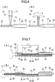
Fig. 7] Fig. 7 is a cross-sectional view illustrating an inserter according to a third embodiment,Fig. 7 (A) illustrates a state where a moving tube is located inside an outer tubular portion, andFig. 7 (B) illustrates a state where the moving tube protrudes to a distal side from the outer tubular portion. - [
Fig. 8] Fig. 8 is a plan view illustrating an inserter according to a fourth embodiment. - [
Fig. 9] Fig. 9 is a plan view illustrating an inserter according to a fifth embodiment. - Hereinafter, embodiments according to the present invention will be described with reference to the drawings. In some case, dimensions in the drawings may be exaggerated and differ from actual dimensions for convenience of description. In addition, in the present specification and the drawings, the same reference numerals will be assigned to configuration elements having substantially the same function, and thus, repeated description will be omitted. In the present specification, a side to be inserted into a lumen will be referred to as a "distal side", and an operating hand-side will be referred to as a "proximal side".
- As illustrated in
Fig. 1 , aninserter 20 according to a first embodiment is a device included in a medical elongated body set 10 that accommodates a medicalelongated body 40 which is a guide wire in order to store and transport the medicalelongated body 40. Theinserter 20 assists a distal portion of the medicalelongated body 40 to be inserted into a medical device 61 (to be described later, refer toFig. 4(D) ). - The medical elongated body set 10 has a
holder 50 which is a pipe body for accommodating at least a portion of the medicalelongated body 40, aholding portion 51 for holding theholder 50, aninserter 20 connected to an end portion of theholder 50, and the medicalelongated body 40 held by theholder 50 and theinserter 20. - A tube extending with a predetermined length is wound around the
holder 50, and theholder 50 has a spiral shape as a whole. A shape of theholder 50 is not particularly limited, and may be an elliptical shape, for example. A length of theholder 50 in a major axis direction is shorter than a length of the medicalelongated body 40. Theinserter 20 is connected to onefirst end portion 52 of theholder 50. A proximal portion of the medicalelongated body 40 is pulled out from asecond end portion 53 of theholder 50 to which theinserter 20 is not connected. Therefore, an operator can grip the proximal portion of the medicalelongated body 40 pulled out from thesecond end portion 53 of theholder 50, and can push the proximal portion toward a distal side, can pull the proximal portion toward a proximal side, or can rotates the proximal portion. - The holding
portion 51 is a member that holds a shape of theholder 50 having a spiral shape. The holdingportions 51 are disposed at several locations in a winding direction of theholder 50, and fix adjacent tubes to each other in an aligned state. - As illustrated in
Fig. 2 , the medicalelongated body 40 is a guide wire having a puncturing function. The medicalelongated body 40 is used to puncture a fossa ovalis of an atrial septum from a right atrium to form a hole leading from the right atrium to a left atrium. Furthermore, the medicalelongated body 40 guides a movement of a dilator (not illustrated) from the right atrium to the left atrium. - The medical
elongated body 40 includes ashaft portion 41 which is an elongated wire rod, aneedle portion 42 having a sharp needle tip, and acover portion 43 for accommodating theneedle portion 42. For example, thecover portion 43 has a spiral wire rod. Therefore, although thecover portion 43 accommodates theneedle portion 42, thecover portion 43 can expose the needle tip of theneedle portion 42 by contracting to reduce pitches of a spiral. - In general, the guide wire has a certain degree of rigidity and high flexibility so that the guide wire does not damage an insertion target body lumen and can be pushed forward into a meandering body lumen. Therefore, when the medical
elongated body 40 which is the guide wire receives a force acting toward the proximal side in the distal end of thecover portion 43 in a state where bending (deformation in a radial direction) is not restricted, any site of the medicalelongated body 40 is bent, and the force escapes to the other site from the distal end of thecover portion 43. Therefore, even when thecover portion 43 receives the force acting toward the proximal side in the distal end, the force required for contracting thecover portion 43 does not act on thecover portion 43. Therefore, thecover portion 43 is bent by receiving the force acting toward the proximal side in a freely bendable state, and maintains a state where theneedle portion 42 is accommodated. When the medicalelongated body 40 is inserted into a pipe body such as amedical device 61 and a dilator (to be described later), the bending is restricted. In this state, the distal end of the medicalelongated body 40 butts against the fossa ovalis so that thecover portion 43 contracts and theneedle portion 42 protrudes. In this manner, the medicalelongated body 40 can form a hole in the fossa ovalis. - As illustrated in
Figs. 1 and3 , theinserter 20 has atubular portion 21 connected to theholder 50 and aconnector 31 connectable to thetubular portion 21. - The
tubular portion 21 has aproximal opening portion 22 connected to theholder 50, adistal opening portion 23 that can be connected to theconnector 31, and adecreased diameter portion 24 located between theproximal opening portion 22 and thedistal opening portion 23. Theproximal opening portion 22 covers an end portion of theholder 50, and is connected to theholder 50. Theproximal opening portion 22 can be detached from theholder 50. Thetubular portion 21 internally has amain lumen 25 penetrating thedistal opening portion 23 from theproximal opening portion 22. Depending on an outer diameter of theholder 50 and an inner diameter of theconnector 31, an inner diameter of the decreaseddiameter portion 24 may be the same as an inner diameter of thetubular portion 21. In addition, theproximal opening portion 22 may be separated from the end portion of theholder 50. - The
distal opening portion 23 can be connected to theconnector 31, and can be inserted into themedical device 61 in order to guide the medicalelongated body 40 to themedical device 61. The outer diameter and the inner diameter of thedistal opening portion 23 are smaller than the outer diameter and the inner diameter of theproximal opening portion 22. Furthermore, the outer diameter and the inner diameter of thedistal opening portion 23 are smaller than the inner diameter of themedical device 61. Therefore, thedistal opening portion 23 can easily guide the medicalelongated body 40 to the thinmedical device 61. The outer diameter of the distal end of thedistal opening portion 23 decreases toward the distal side in a tapered shape. In this manner, thedistal opening portion 23 is likely to be inserted into theconnector 31 or themedical device 61. Themedical device 61 is a reinforcement tube formed by the medicalelongated body 40 and inserted into a dilator to widen a hole in the fossa ovalis in an atrial septal puncture, for example. Themedical device 61 may be the dilator. - The decreased
diameter portion 24 is a portion where the inner diameter and the outer diameter are changed between the thickproximal opening portion 22 that can cover theholder 50 and the thindistal opening portion 23 that can be inserted into themedical device 61. The inner diameter and the outer diameter of the decreaseddiameter portion 24 decrease toward the distal side in a tapered shape. A tapered inner surface of the decreaseddiameter portion 24 serves to smoothly guide the medicalelongated body 40 located therein to the distal side. - The
connector 31 has aninterlock portion 32 that can be interlocked with thedistal opening portion 23 of thetubular portion 21 and an injectiontool interlock portion 33 that can be connected to a liquid injection tool 60 (refer toFig. 4 ). Thedistal opening portion 23 can be connected to an inner surface of theinterlock portion 32. For example, the connection means combination or contact. Therefore, the inner diameter of theinterlock portion 32 substantially coincides with the outer diameter of thedistal opening portion 23. For example, a distal tube of theliquid injection tool 60 which is a syringe can be fitted to an inner surface of the injectiontool interlock portion 33. Therefore, the inner diameter of the injectiontool interlock portion 33 substantially coincides with the outer diameter of the distal tube of theliquid injection tool 60. An outer surface of the injectiontool interlock portion 33 has aprojection portion 34 that can be connected to a rotary connector (not illustrated) rotatably provided on the distal tube of theliquid injection tool 60. Theprojection portion 34 may not be formed. Theconnector 31 has aconnector lumen 35 penetrating theinterlock portion 32 from the injectiontool interlock portion 33. - The inner diameter of the
distal opening portion 23 is not particularly limited, but is 0.1 to 10 mm, for example. The outer diameter of thedistal opening portion 23 is not particularly limited, but is 0.2 to 20 mm, for example. The inner diameter of theproximal opening portion 22 is not particularly limited, but is 0.5 to 25 mm, for example. The outer diameter of theproximal opening portion 22 is not particularly limited, but is 1 to 50 mm, for example. The inner diameter of the injectiontool interlock portion 33 is not particularly limited, but is 0.4 to 40 mm, for example. - Each configuration material of the
tubular portion 21 and theconnector 31 is not particularly limited as long as the materials have a certain level of strength. For example, polyolefin such as polyethylene, polypropylene, and ethylene-propylene copolymer, or various resin materials such as polyvinyl chloride, polystyrene, polyamide, and polycarbonate, and acrylic resins can be adopted. The configuration material of thetubular portion 21 and theconnector 31 may be a metallic material. - Next, a method of using the
inserter 20 according to the first embodiment will be described with reference to a flowchart illustrated inFig. 5 . - First, as illustrated in
Fig. 4(A) , an operator inserts the distal tube of theliquid injection tool 60 into the injectiontool interlock portion 33 of theconnector 31. In this manner, theconnector 31 is connected to the liquid injection tool 60 (Step S10). The distal portion of the medicalelongated body 40 is in a state where the distal portion is pulled out to the distal side from thedistal opening portion 23 of theinserter 20. - Next, as illustrated in
Fig. 4(B) , the operator pulls the proximal portion of the medicalelongated body 40 pulled out from asecond end portion 53 on a side opposite to a side to which theinserter 20 of theholder 50 is connected. In this manner, the distal portion of the medicalelongated body 40 is pulled into themain lumen 25 inside the inserter 20 (Step S11). In this manner, theinserter 20 is in a state where thedistal opening portion 23 of thetubular portion 21 can be connected to theinterlock portion 32 of theconnector 31. - Next, as illustrated in
Fig. 4(C) , the operator connects thedistal opening portion 23 of thetubular portion 21 to theinterlock portion 32 of the connector 31 (Step S12). A distal surface or an outer peripheral surface located in the distal portion of thedistal opening portion 23 is attached to afirst attachment portion 36 located on an inner peripheral surface of theinterlock portion 32. Next, the operator releases a liquid such as a physiological salt solution from theliquid injection tool 60. In this manner, the liquid is injected into themain lumen 25 of thetubular portion 21 through theconnector 31. The liquid injected into themain lumen 25 fills the inside of theinserter 20, and further flows into theholder 50. The liquid flowing into theholder 50 fills the inside of theholder 50, and is removed from asecond end portion 53 of theholder 50. In this manner, priming can be performed from the distal side on the medicalelongated body 40 inside theinserter 20 and the holder 50 (Step S13). - Next, the operator separates the
distal opening portion 23 of thetubular portion 21 from theinterlock portion 32 of the connector 31 (Step S14). Next, as illustrated inFig. 4(D) , the operator inserts thedistal opening portion 23 of thetubular portion 21 into an opening portion on the proximal side of the medical device 61 (Step S15). A distal surface or an outer peripheral surface located in the distal portion of thedistal opening portion 23 is attached to asecond attachment portion 63 located on an inner peripheral surface of ahub 62 of themedical device 61. Thehub 62 is a portion that enables other devices to be inserted or to be connected. Next, the operator pushes the medicalelongated body 40 pulled out from thesecond end portion 53 of theholder 50, and inserts the medicalelongated body 40 into the medical device 61 (Step S16). Next, in a state where the medicalelongated body 40 is left inside themedical device 61, thedistal opening portion 23 of thetubular portion 21 is removed from the medical device 61 (Step S17). Theholder 50 may be detached from theproximal opening portion 22 of thetubular portion 21, before thedistal opening portion 23 of thetubular portion 21 is removed from themedical device 61. Next, the whole medicalelongated body 40 is taken out to the distal side from theholder 50 and the inserter 20 (Step S18) . Thereafter, the operator can perform a medical procedure using themedical device 61. - As described above, the
inserter 20 according to the first embodiment is theinserter 20 that assists the medicalelongated body 40 to be inserted into themedical device 61, and has thetubular portion 21 having theproximal opening portion 22 into which the medicalelongated body 40 is inserted and thedistal opening portion 23 that guides the medicalelongated body 40 to themedical device 61, and having themain lumen 25 through which theproximal opening portion 22 and thedistal opening portion 23 communicate with each other, and theconnector 31 that can communicate with themain lumen 25 of thetubular portion 21 and can connect theliquid injection tool 60. - The
inserter 20 configured as described above injects the liquid from theliquid injection tool 60 connected to theconnector 31. In this manner, priming can be performed from the distal portion on the medicalelongated body 40 located in themain lumen 25 of thetubular portion 21. Therefore, theinserter 20 can effectively remove air remaining inside the distal portion by effectively performing the priming on the distal portion of the medicalelongated body 40. - In addition, the
connector 31 can be connected to thedistal opening portion 23 of thetubular portion 21. In this manner, theinserter 20 injects the liquid from theconnector 31 connected to thedistal opening portion 23 so that the priming can be effectively performed from the distal side on the medicalelongated body 40 located in themain lumen 25 of thetubular portion 21. - In addition, the medical elongated body set 10 in the present embodiment has the medical
elongated body 40 in which theneedle portion 42 and thecover portion 43 that covers theneedle portion 42 to be exposed are disposed in the distal portion of theelongated shaft portion 41, theholder 50 which is a pipe body that accommodates at least a portion of the medicalelongated body 40, and theinserter 20 connected to an end portion of theholder 50. Theinserter 20 has thetubular portion 21 having theproximal opening portion 22 into which the distal portion of the medicalelongated body 40 is inserted and thedistal opening portion 23 that guides the medicalelongated body 40 to themedical device 61, and having themain lumen 25 through which theproximal opening portion 22 and thedistal opening portion 23 communicate with each other, and theconnector 31 that communicates with themain lumen 25 of thetubular portion 21, and connects theliquid injection tool 60. - The medical elongated body set 10 configured as described above injects the liquid from the
liquid injection tool 60 connected to theconnector 31 of theinserter 20 so that the priming can be performed from the distal portion on the medicalelongated body 40 located in themain lumen 25 of thetubular portion 21. Therefore, the medical elongated body set 10 can effectively remove the air remaining inside thecover portion 43 located in the distal portion of the medicalelongated body 40. - In addition, the medical elongated body set 10 has the dilator or the reinforcement tube that can be inserted into the dilator as the
medical device 61. Theconnector 31 has theinterlock portion 32 which thedistal opening portion 23 can be inserted into and connected to. The inner diameter of the lumen of thehub 62 of themedical device 61 is substantially coincides with the inner diameter of theinterlock portion 32. In this manner, thedistal opening portion 23 of thetubular portion 21 can be satisfactorily connected to theinterlock portion 32 of theconnector 31, and can be satisfactorily connected to thehub 62 of themedical device 61. - In addition, the distal portion of the
distal opening portion 23 can be attached to thefirst attachment portion 36 of theconnector 31 and thesecond attachment portion 63 of thehub 62 of themedical device 61. In this manner, the distal portion of thedistal opening portion 23 can be satisfactorily connected to thehub 62 and theinterlock portion 32 of themedical device 61. - In addition, the method of using the
inserter 20 in the present embodiment includes Step S10 of connecting theliquid injection tool 60 to theinserter 20 connected to the end portion of theholder 50 which is the pipe body that accommodates at least a portion of a medicalelongated body 40, Step S13 of supplying the liquid to theinserter 20 from theliquid injection tool 60, and performing priming on the medicalelongated body 40, Step S15 of inserting theinserter 20 into themedical device 61, and Step S16 of inserting the medicalelongated body 40 into themedical device 61 from theinserter 20. - According to the method of using the
inserter 20 configured as described above, the liquid is injected from theliquid injection tool 60 connected to theinserter 20 so that the priming can be performed from the distal portion on the medicalelongated body 40 disposed inside theinserter 20. Therefore, theinserter 20 can effectively remove the air remaining inside the distal portion of the medicalelongated body 40. Then, the medicalelongated body 40 on which the priming is satisfactorily performed can be easily inserted into themedical device 61 via theinserter 20 by an operator. - In addition, the above-described method of using the
inserter 20 has Step S11 of pulling the distal portion of the medicalelongated body 40 protruding to the distal side from theinserter 20 into theinserter 20, before the step of connecting theliquid injection tool 60 to theinserter 20. In this manner, the liquid can be injected into theinserter 20 in a state where the distal portion of the medicalelongated body 40 is disposed inside theinserter 20. Therefore, the operator can effectively perform the priming on the distal portion of the medicalelongated body 40 disposed inside the medicalelongated body 40. - An
inserter 70 according to a second embodiment is different from that according to the first embodiment in that aconnector 71 is integrated with thetubular portion 21 as illustrated inFig. 6(A) . - The
connector 71 is formed in anauxiliary tube 73 bifurcated from thetubular portion 21. Theauxiliary tube 73 has anauxiliary lumen 72 communicating with themain lumen 25. In this manner, in theinserter 70, the liquid is injected from theconnector 71 formed in theauxiliary tube 73 so that the priming can be effectively performed from the distal side on the medicalelongated body 40 located in themain lumen 25 of thetubular portion 21. Furthermore, theconnector 71 is not disposed in thedistal opening portion 23. Accordingly, the movement of the medicalelongated body 40 from theproximal opening portion 22 to thedistal opening portion 23 is not hindered by theliquid injection tool 60 connected to theconnector 71. In addition, theliquid injection tool 60 can be connected to theconnector 71 without using a separate connector. Accordingly, the priming can be easily performed. - The
connector 71 may be disposed in theauxiliary tube 73 to be detachable therefrom. A detachable structure can be similar to a structure (refer toFig. 3 ) of theconnector 31 with respect to thedistal opening portion 23 according to the first embodiment. - As a modification example of the
inserter 70 according to the second embodiment, as illustrated inFig. 6(B) , theconnector 71 may be inserted into theliquid injection tool 60 instead of covering theliquid injection tool 60. In this case, theconnector 71 has the outer diameter that can be inserted into theliquid injection tool 60. It is preferable that the outer diameter of theconnector 71 is different from the outer diameter of thedistal opening portion 23. In this manner, theconnector 71 can be connected only to theliquid injection tool 60, and thedistal opening portion 23 can be connected only to themedical device 61. Therefore, it is possible to suppress a possibility that the operator may make a mistake in selecting a connecting destination of theliquid injection tool 60 and themedical device 61. The outer diameter of theconnector 71 may be the same as the outer diameter of thedistal opening portion 23. In this case, theconnector 71 and thedistal opening portion 23 can be connected to both theliquid injection tool 60 and themedical device 61. Therefore, for example, theliquid injection tool 60 can be connected to thedistal opening portion 23, and the priming can be performed from thedistal opening portion 23. In this case, thedistal opening portion 23 also functions as theconnector 71. In a case where thedistal opening portion 23 can also function as theconnector 71, theauxiliary tube 73 and theauxiliary lumen 72 inFig. 6(B) may be omitted. - An
inserter 80 according to a third embodiment is different from that according to the first embodiment in that adistal opening portion 92 which can be connected to themedical device 61 can protrude from theconnector 83 as illustrated inFig. 7 . - The
inserter 80 has an outertubular portion 81, a movingtube 91 disposed to be movable inside the outertubular portion 81, and aconnector 83 integrally formed with the outertubular portion 81. - The outer
tubular portion 81 has aproximal opening portion 82 connected to theholder 50. Theproximal opening portion 82 covers thefirst end portion 52 of theholder 50, and is connected to theholder 50 to be detachable therefrom. The outertubular portion 81 internally has anouter lumen 84 penetrating theconnector 83 from theproximal opening portion 82. The outertubular portion 81 has alateral exposure surface 85 whose inner surface is exposed in a direction intersecting with an axis of theouter lumen 84. Thelateral exposure surface 85 is also a portion of theouter lumen 84. The movingtube 91 is exposed from thelateral exposure surface 85. Adistal locking portion 86 and aproximal locking portion 87 whose inner diameter decreases are formed on the distal side and the proximal side on which thelateral exposure surface 85 of theouter lumen 84 is pinched therebetween. Aconvex portion 88 for slip stopping is formed on the outer peripheral surface of the outertubular portion 81. It is preferable that theconvex portion 88 is formed on the outer peripheral surface of thelateral exposure surface 85. In this manner, the operator is likely to operate a portion exposed from thelateral exposure surface 85. Theconvex portion 88 may be formed in another portion on the outer peripheral surface of the outertubular portion 81. - The moving
tube 91 has a tubulardistal opening portion 92 having the movinglumen 96, and asupport portion 93 located on the proximal side from thedistal opening portion 92. The outer peripheral surface of the proximal portion of thedistal opening portion 92 has a lockingconvex portion 94 protruding toward thelateral exposure surface 85, and an operatingconvex portion 95 protruding in a direction opposite thereto. The movingtube 91 moves to the distal side inside theouter lumen 84 of the outertubular portion 81. In this manner, the lockingconvex portion 94 comes into contact with thedistal locking portion 86, and the movement is restricted. The movingtube 91 moves to the proximal side inside theouter lumen 84 of the outertubular portion 81. In this manner, the lockingconvex portion 94 comes into contact with theproximal locking portion 87, and the movement is restricted. In this manner, the movingtube 91 is satisfactorily held without falling off from the outertubular portion 81. The operatingconvex portion 95 is a portion operated by the operator with a finger, when the movingtube 91 is moved to the distal side or the proximal side with respect to the outertubular portion 81. - As illustrated in
Fig. 7(A) , theliquid injection tool 60 can be connected to theconnector 83 in a state where the movingtube 91 is located inside the outertubular portion 81. In this case, a length L1 along the axis of the movinglumen 96 formed in thedistal opening portion 92 is longer than a length L2 along the axis of thelateral exposure surface 85. Therefore, the liquid injected from theliquid injection tool 60 does not leak from thelateral exposure surface 85, and can flow to the proximal side through the movinglumen 96. - As illustrated in
Fig. 7(B) , thedistal opening portion 92 can be inserted into themedical device 61 in a state where the movingtube 91 protrudes to the distal side from the outertubular portion 81. The movingtube 91 having thedistal opening portion 92 and the outertubular portion 81 having theproximal opening portion 82 form the tubular portion having the main lumen. That is, the main lumen is formed by the movinglumen 96 and theouter lumen 84. Thesupport portion 93 is located on the proximal side from the movinglumen 96, and is disposed on a side where thelateral exposure surface 85 is located with respect to the axis of theouter lumen 84. The medicalelongated body 40 passes through the movinglumen 96 to be located away from thelateral exposure surface 85 on the proximal side of the movinglumen 96. Thesupport portion 93 supports the medicalelongated body 40 located away from thelateral exposure surface 85. - As described above, the
inserter 80 according to the third embodiment has the outertubular portion 81 integrated with theconnector 83, and having theproximal opening portion 82 and theouter lumen 84 through which theproximal opening portion 82 communicates with theconnector 83, and the movingtube 91 disposed to be movable along the axis of theouter lumen 84 inside theouter lumen 84, and internally having the movinglumen 96. The movingtube 91 has thedistal opening portion 92 formed on the distal side. The movinglumen 96 communicates with theouter lumen 84. The movingtube 91 can protrude to the distal side from theconnector 83. In this manner, theinserter 80 can connect theliquid injection tool 60 to theconnector 83 by moving the movingtube 91 to the proximal side. Therefore, thedistal opening portion 92 does not interfere with the connection, when theliquid injection tool 60 is connected to theconnector 83. Furthermore, theinserter 80 can insert the movingtube 91 into themedical device 61 by moving the movingtube 91 to the distal side and causing the movingtube 91 to protrude to the distal side from theconnector 83. - In addition, the outer
tubular portion 81 has thelateral exposure surface 85 whose inner surface is exposed in a direction intersecting with the axis of theouter lumen 84. In this manner, in theinserter 80, the medicalelongated body 40 can be exposed outward from thelateral exposure surface 85. Therefore, the operator can operate the medicalelongated body 40 exposed from thelateral exposure surface 85. Accordingly, for example, the operator can operate the medicalelongated body 40 exposed from thelateral exposure surface 85 with fingers of a hand gripping theinserter 80. Therefore, the operator can operate theinserter 80 and the medicalelongated body 40 with one hand, and can operate the other device with the other hand. In addition, although theneedle portion 42 is disposed in the distal portion of the medicalelongated body 40, the operator can safely operate the medicalelongated body 40 without touching the needle tip of theneedle portion 42. In addition, the operator does not need to touch the distal portion of the medicalelongated body 40. Accordingly, it is possible to suppress damage to the distal portion of the medicalelongated body 40. - In addition, the outer
tubular portion 81 has thelateral exposure surface 85 whose inner surface is exposed in the direction intersecting with the axis of theouter lumen 84, and the length in the direction along the axis of the movinglumen 96 is longer than the length in the direction along the axis of thelateral exposure surface 85. In this manner, the movingtube 91 accommodated in the outertubular portion 81 can close thelateral exposure surface 85. Therefore, it is possible to suppress a possibility that a priming liquid injected from theconnector 83 may leak out. - In addition, the outer
tubular portion 81 has thelateral exposure surface 85 whose inner surface is exposed in the direction intersecting with the axis of theouter lumen 84. The movingtube 91 has thesupport portion 93 disposed on the proximal side from the movinglumen 96, and disposed on a side where thelateral exposure surface 85 is located with respect to the axis of theouter lumen 84. In a state where the movingtube 91 protrudes to the distal side from the outertubular portion 81, thesupport portion 93 is exposed on thelateral exposure surface 85. In a state where the movingtube 91 is located inside the outertubular portion 81, a portion from the distal end to the proximal end of thesupport portion 93 is located inside the outertubular portion 81. In this manner, in theinserter 80, the medicalelongated body 40 can be exposed outward while being supported by thesupport portion 93 on thelateral exposure surface 85 exposed outward. Therefore, the operator can satisfactorily operate the medicalelongated body 40 exposed outward. In this case, the medicalelongated body 40 located away from thelateral exposure surface 85 passes through the movinglumen 96 to be supported by thesupport portion 93 located on the proximal side of the movinglumen 96. Therefore, the operator is likely to transmit a force to the medicalelongated body 40. In addition, the operator can operate the medicalelongated body 40 exposed from thelateral exposure surface 85 with the fingers of the hand gripping theinserter 80. Therefore, the operator can operate theinserter 80 with one hand, and can operate the other device with the other hand. In addition, when theneedle portion 42 is located in the distal end of the medicalelongated body 40, the operator can safely operate the medicalelongated body 40 without touching the needle tip of theneedle portion 42. In addition, the operator does not need to touch the distal portion of the medicalelongated body 40. Accordingly, it is possible to suppress damage to the distal portion of the medicalelongated body 40. - An
inserter 100 according to a fourth embodiment is different from that according to the first embodiment in that alateral exposure surface 102 is formed in atubular portion 101 as illustrated inFig. 8 . - The
tubular portion 101 has thelateral exposure surface 102 whose inner surface is exposed in the direction intersecting with the axis of themain lumen 25. Therefore, the operator can satisfactorily operate the medicalelongated body 40 exposed outward from thelateral exposure surface 102. The operator can operate the medicalelongated body 40 exposed from thelateral exposure surface 102 with the fingers of the hand gripping theinserter 100. Thelateral exposure surface 102 has at least one supportingconvex portion 103. The supportingconvex portion 103 serves to cause the medicalelongated body 40 to float from thelateral exposure surface 102. In this manner, the operator is likely to touch the medicalelongated body 40, and easily operates the medicalelongated body 40. - An
inserter 110 according to a fifth embodiment is different from that according to the first embodiment in that asupport body 112 is provided between theproximal opening portion 22 and thedistal opening portion 23 of atubular portion 111 as illustrated inFig. 9 . - The
tubular portion 111 has thesupport body 112 having a holdingportion 113 for holding theholder 50 to be wound. Thesupport body 112 extends to be curved in a direction away from themain lumen 25 from each of theproximal opening portion 22 and thedistal opening portion 23. Therefore, a space is formed between theproximal opening portion 22 and thedistal opening portion 23. Therefore, the operator can easily operate the medicalelongated body 40 located in this space. - The present invention is not limited only to the above-described embodiments, and various modifications can be made by those skilled in the art within the technical idea of the present invention. For example, the medical
elongated body 40 is not particularly limited as long as the medicalelongated body 40 is an elongated device inserted into a living body. For example, a device such as a guide wire or a catheter having no needle portion may be adopted. - In addition, in the
inserter 80 according to the third embodiment, thelateral exposure surface 85 may not be formed, and the movingtube 91 may not be exposed in an intermediate portion of the outertubular portion 81. A spring that biases the movingtube 91 in a distal direction may be disposed inside the outertubular portion 81. - In addition, a structure similar to the supporting
convex portion 103 formed on thelateral exposure surface 102 of theinserter 100 according to the fourth embodiment may be formed in thesupport portion 93 of theinserter 80 according to the third embodiment. - In addition, the structure in each of the above-described embodiments can be appropriately applied to other embodiments.
- This application is based on
Japanese Patent Application No. 2019-026188 filed on February 18, 2019 -
- 10 medical elongated body set
- 20, 70, 80, 100, 110 inserter
- 21, 21, 101, 111 tubular portion
- 22, 82 proximal opening portion
- 23, 92 distal opening portion
- 25 main lumen
- 31, 71, 83, 83 connector
- 32 interlock portion
- 33 injection tool interlock portion
- 36 first attachment portion
- 40 medical elongated body
- 41 shaft portion
- 42 needle portion
- 43 cover portion
- 50 holder
- 52 first end portion
- 53 second end portion
- 60 liquid injection tool
- 61 medical device
- 62 hub
- 63 second attachment portion
- 72 auxiliary lumen
- 73 auxiliary tube
- 81 outer tubular portion
- 84 outer lumen
- 85, 92, 102 lateral exposure surface
- 91 moving tube
- 93 support portion
- 96 moving lumen
- 103 supporting convex portion
Claims (13)
- An inserter that assists a medical elongated body to be inserted into a medical device, comprising:a tubular portion having a proximal opening portion into which the medical elongated body is inserted, a distal opening portion that guides the medical elongated body to the medical device, and a main lumen through which the proximal opening portion and the distal opening portion communicate with each other; anda connector that communicates with the main lumen of the tubular portion, and connects a liquid injection tool.
- The inserter according to Claim 1,
wherein the connector is formed in or is connected to the distal opening portion of the tubular portion. - The inserter according to Claim 1,
wherein the connector is formed in an auxiliary tube having an auxiliary lumen bifurcated from the tubular portion and communicating with the main lumen, or is connected to the auxiliary tube. - The inserter according to Claim 2, further comprising:an outer tubular portion integrated with the connector, and having the proximal opening portion and an outer lumen through which the proximal opening portion communicates with the connector; anda moving tube disposed inside the outer lumen to be movable along an axis of the outer lumen, and internally having the moving lumen,wherein a distal side of the moving tube has the distal opening portion, and the moving lumen communicates with the outer lumen, andthe moving tube protrudes to the distal side from the connector.
- The inserter according to any one of Claims 1 to 4,
wherein the outer tubular portion has a lateral exposure surface whose inner surface is exposed in a direction intersecting with an axis of the outer lumen. - The inserter according to Claim 4,wherein the outer tubular portion has a lateral exposure surface whose inner surface is exposed in a direction intersecting the axis of the outer lumen, anda length of the moving lumen in a direction extending along the axis is equal to or longer than a length of the lateral exposure surface in a direction extending along the axis.
- The inserter according to Claim 4,wherein the outer tubular portion has a lateral exposure surface whose inner surface is exposed in a direction intersecting with the axis of the outer lumen,the moving tube has a support portion disposed on a proximal side of the moving lumen, and disposed on a side where the lateral exposure surface is located with respect to the axis of the outer lumen,in a state where the moving tube protrudes to the distal side from the outer tubular portion, the support portion is exposed on the lateral exposure surface, andin a state where the moving tube is located inside the outer tubular portion, a portion from a distal end to a proximal end of the support portion is located inside the outer tubular portion.
- The inserter according to any one of Claims 1 to 7,wherein the connector has an outer diameter insertable into the liquid injection tool, andthe outer diameter of the connector is different from an outer diameter of the distal opening portion.
- A medical elongated body set comprising:a medical elongated body in which a needle portion and a cover portion that covers the needle portion to be exposed are disposed in a distal portion of an elongated shaft portion;a holder which is a pipe body that accommodates at least a portion of the medical elongated body; andan inserter connected to an end portion of the holder,wherein the inserter hasa tubular portion having a proximal opening portion into which a distal portion of the medical elongated body is inserted, a distal opening portion that guides the medical elongated body to the medical device, and a main lumen through which the proximal opening portion and the distal opening portion communicate with each other, anda connector that communicates with the main lumen of the tubular portion, and connects a liquid injection tool.
- The medical elongated body set according to Claim 9,wherein a dilator or a reinforcement tube insertable into the dilator is provided as the medical device,the connector has an interlock portion which the distal opening portion is inserted into and interlocked with, andan inner diameter of a lumen of a hub of the medical device substantially coincides with an inner diameter of the interlock portion.
- The medical elongated body set according to Claim 10, wherein a distal portion of the distal opening portion is attachable to a first attachment portion of the connector and a second attachment portion of the hub of the medical device.
- A method of using an inserter, comprising:a step of connecting a liquid injection tool to an inserter connected to an end portion of a holder which is a pipe body that accommodates at least a portion of a medical elongated body;a step of supplying a liquid to the inserter from the liquid injection tool, and performing priming on the medical elongated body;a step of inserting the inserter into the medical device; anda step of inserting the medical elongated body into the medical device from the inserter.
- The method of using an inserter according to Claim 12, further comprising:a step of pulling a distal portion of the medical elongated body protruding to a distal side from the inserter into the inserter, before the step of connecting the liquid injection tool to the inserter.
Applications Claiming Priority (2)
| Application Number | Priority Date | Filing Date | Title |
|---|---|---|---|
| JP2019026188 | 2019-02-18 | ||
| PCT/JP2020/003455 WO2020170755A1 (en) | 2019-02-18 | 2020-01-30 | Inserter, medical long item set, and method for using inserter |
Publications (2)
| Publication Number | Publication Date |
|---|---|
| EP3906961A1 true EP3906961A1 (en) | 2021-11-10 |
| EP3906961A4 EP3906961A4 (en) | 2022-03-30 |
Family
ID=72144260
Family Applications (1)
| Application Number | Title | Priority Date | Filing Date |
|---|---|---|---|
| EP20760257.4A Pending EP3906961A4 (en) | 2019-02-18 | 2020-01-30 | INSERT DEVICE, MEDICAL ELONGATED ARTICLE ASSEMBLY AND METHOD OF USING INSERT DEVICE |
Country Status (5)
| Country | Link |
|---|---|
| US (1) | US12478766B2 (en) |
| EP (1) | EP3906961A4 (en) |
| JP (1) | JP7407788B2 (en) |
| CN (1) | CN113301940B (en) |
| WO (1) | WO2020170755A1 (en) |
Families Citing this family (1)
| Publication number | Priority date | Publication date | Assignee | Title |
|---|---|---|---|---|
| CN114159675A (en) * | 2020-09-11 | 2022-03-11 | 约翰·威廉·彼得·马尔斯曼 | Guide wire kit |
Family Cites Families (18)
| Publication number | Priority date | Publication date | Assignee | Title |
|---|---|---|---|---|
| US5273052A (en) * | 1992-01-08 | 1993-12-28 | Danforth Biomedical, Incorporated | Guidewire with reversible contact seal for releasable securement to catheter |
| US5320613A (en) * | 1993-01-06 | 1994-06-14 | Scimed Life Systems, Inc. | Medical lumen flushing and guide wire loading device and method |
| DE19542912C2 (en) | 1995-11-17 | 1999-07-08 | Michael Greive | Insertion aid for stretching a guide wire and securing the guide wire in a dispenser tube and connecting element for connecting the insertion aid to the dispenser tube |
| US6606515B1 (en) * | 1996-09-13 | 2003-08-12 | Scimed Life Systems, Inc. | Guide wire insertion and re-insertion tools and methods of use |
| JP3325798B2 (en) * | 1997-04-25 | 2002-09-17 | 川澄化学工業株式会社 | Guide wire slider and insertion aid |
| US20040147908A1 (en) * | 2003-01-24 | 2004-07-29 | Niall Duffy | Accessory for over the wire catheter with short wire capability |
| JP4280526B2 (en) * | 2003-03-26 | 2009-06-17 | テルモ株式会社 | Medical instruments |
| JP4653958B2 (en) * | 2004-03-01 | 2011-03-16 | テルモ株式会社 | Guide wire inserter |
| DE602005007397D1 (en) | 2004-03-01 | 2008-07-24 | Terumo Corp | Device for introducing elongated medical goods |
| JP4710280B2 (en) * | 2004-08-31 | 2011-06-29 | 株式会社ジェイ・エム・エス | Flushing device and catheter set |
| JP4758688B2 (en) * | 2005-06-21 | 2011-08-31 | テルモ株式会社 | Puncture tool and guide wire insertion tool |
| JP4763553B2 (en) * | 2006-08-28 | 2011-08-31 | 株式会社パイオラックスメディカルデバイス | Guide wire holder |
| US20150306356A1 (en) * | 2014-03-31 | 2015-10-29 | Sukhjit Gill | Catheter Insertion Device |
| US20170014599A1 (en) * | 2015-07-14 | 2017-01-19 | Smiths Medical Asd, Inc. | Device for dispensing a flexible member |
| CA2994368A1 (en) * | 2015-08-23 | 2017-03-02 | Microbot Medical Ltd | Double concentric guidewire |
| WO2018163899A1 (en) * | 2017-03-06 | 2018-09-13 | テルモ株式会社 | Puncture device, medical device, and treatment method |
| AU2018243038B2 (en) * | 2017-03-31 | 2021-02-04 | Terumo Kabushiki Kaisha | Guide wire, medical device, and treatment method |
| JP2019026188A (en) | 2017-08-03 | 2019-02-21 | 本田技研工業株式会社 | Hybrid drive unit |
-
2020
- 2020-01-30 WO PCT/JP2020/003455 patent/WO2020170755A1/en not_active Ceased
- 2020-01-30 EP EP20760257.4A patent/EP3906961A4/en active Pending
- 2020-01-30 CN CN202080008876.4A patent/CN113301940B/en active Active
- 2020-01-30 JP JP2021501789A patent/JP7407788B2/en active Active
-
2021
- 2021-08-18 US US17/405,214 patent/US12478766B2/en active Active
Also Published As
| Publication number | Publication date |
|---|---|
| JPWO2020170755A1 (en) | 2021-12-16 |
| CN113301940B (en) | 2024-04-09 |
| US20210379342A1 (en) | 2021-12-09 |
| WO2020170755A1 (en) | 2020-08-27 |
| EP3906961A4 (en) | 2022-03-30 |
| US12478766B2 (en) | 2025-11-25 |
| JP7407788B2 (en) | 2024-01-04 |
| CN113301940A (en) | 2021-08-24 |
Similar Documents
| Publication | Publication Date | Title |
|---|---|---|
| JP6721735B2 (en) | Catheter assembly | |
| US9408667B2 (en) | Guide sheath and guide sheath system | |
| US20050234507A1 (en) | Medical tool for access to internal tissue | |
| CN107530526B (en) | Catheter assembly | |
| US20160243355A1 (en) | Catheters for deploying implantable medical devices, and associated tethering assemblies and methods | |
| US20100274129A1 (en) | Apparatus And Methods for Separating Pericardial Tissue From The Epicardium of the Heart | |
| JP5248659B2 (en) | Dilator device for ventricular puncture | |
| JP2008518672A (en) | Universal catheter inserter | |
| GB2240926A (en) | An expansible cannula | |
| US8996135B2 (en) | Device and method for inserting a cardiac catheter | |
| US20240065731A1 (en) | Catheter system for left heart access | |
| US11660119B2 (en) | Catheter system for left heart access | |
| CN111741788A (en) | Guide wire and medical device | |
| EP3060137B1 (en) | Transseptal crossing needle device | |
| US12478766B2 (en) | Inserter, medical elongated body set that includes inserter, and method of using inserter | |
| EP4137074A1 (en) | Puncture needle assembly and puncture system | |
| JP4231304B2 (en) | Guide wire inserter | |
| CN114642481A (en) | Bendable puncture needle and puncture system | |
| JP2010012052A (en) | Gastric fistula catheter and gastric fistula catheter kit | |
| EP3294399B1 (en) | Catheter system for left heart access | |
| EP1013304B1 (en) | A device for guiding and positioning leads |
Legal Events
| Date | Code | Title | Description |
|---|---|---|---|
| STAA | Information on the status of an ep patent application or granted ep patent |
Free format text: STATUS: THE INTERNATIONAL PUBLICATION HAS BEEN MADE |
|
| PUAI | Public reference made under article 153(3) epc to a published international application that has entered the european phase |
Free format text: ORIGINAL CODE: 0009012 |
|
| STAA | Information on the status of an ep patent application or granted ep patent |
Free format text: STATUS: REQUEST FOR EXAMINATION WAS MADE |
|
| 17P | Request for examination filed |
Effective date: 20210804 |
|
| AK | Designated contracting states |
Kind code of ref document: A1 Designated state(s): AL AT BE BG CH CY CZ DE DK EE ES FI FR GB GR HR HU IE IS IT LI LT LU LV MC MK MT NL NO PL PT RO RS SE SI SK SM TR |
|
| A4 | Supplementary search report drawn up and despatched |
Effective date: 20220302 |
|
| RIC1 | Information provided on ipc code assigned before grant |
Ipc: A61M 39/10 20060101ALI20220224BHEP Ipc: A61M 25/00 20060101ALI20220224BHEP Ipc: A61B 17/34 20060101ALI20220224BHEP Ipc: A61M 39/08 20060101ALI20220224BHEP Ipc: A61M 39/02 20060101ALI20220224BHEP Ipc: A61M 25/09 20060101AFI20220224BHEP |
|
| DAV | Request for validation of the european patent (deleted) | ||
| DAX | Request for extension of the european patent (deleted) | ||
| STAA | Information on the status of an ep patent application or granted ep patent |
Free format text: STATUS: EXAMINATION IS IN PROGRESS |
|
| 17Q | First examination report despatched |
Effective date: 20250324 |