EP3906211B1 - Valve closure with concentric spring-loaded moving valve members, the internal valve member having axial protrusions - Google Patents
Valve closure with concentric spring-loaded moving valve members, the internal valve member having axial protrusions Download PDFInfo
- Publication number
- EP3906211B1 EP3906211B1 EP19848937.9A EP19848937A EP3906211B1 EP 3906211 B1 EP3906211 B1 EP 3906211B1 EP 19848937 A EP19848937 A EP 19848937A EP 3906211 B1 EP3906211 B1 EP 3906211B1
- Authority
- EP
- European Patent Office
- Prior art keywords
- valve
- valve closure
- coupler according
- dispensing coupler
- closure
- Prior art date
- Legal status (The legal status is an assumption and is not a legal conclusion. Google has not performed a legal analysis and makes no representation as to the accuracy of the status listed.)
- Active
Links
- 239000000523 sample Substances 0.000 claims description 19
- 238000007789 sealing Methods 0.000 claims description 9
- 230000004323 axial length Effects 0.000 claims description 3
- 239000007788 liquid Substances 0.000 description 15
- 235000013405 beer Nutrition 0.000 description 3
- 235000013361 beverage Nutrition 0.000 description 3
- 235000014171 carbonated beverage Nutrition 0.000 description 3
- 238000000855 fermentation Methods 0.000 description 2
- 239000012263 liquid product Substances 0.000 description 2
- 238000000071 blow moulding Methods 0.000 description 1
- 230000001419 dependent effect Effects 0.000 description 1
- 230000004151 fermentation Effects 0.000 description 1
- 239000012530 fluid Substances 0.000 description 1
- 239000000463 material Substances 0.000 description 1
- 239000012528 membrane Substances 0.000 description 1
- 230000004048 modification Effects 0.000 description 1
- 238000012986 modification Methods 0.000 description 1
- 230000002093 peripheral effect Effects 0.000 description 1
- 229920003023 plastic Polymers 0.000 description 1
- 239000004033 plastic Substances 0.000 description 1
- 239000000047 product Substances 0.000 description 1
- 238000003466 welding Methods 0.000 description 1
Images


Classifications
-
- B—PERFORMING OPERATIONS; TRANSPORTING
- B67—OPENING, CLOSING OR CLEANING BOTTLES, JARS OR SIMILAR CONTAINERS; LIQUID HANDLING
- B67D—DISPENSING, DELIVERING OR TRANSFERRING LIQUIDS, NOT OTHERWISE PROVIDED FOR
- B67D1/00—Apparatus or devices for dispensing beverages on draught
- B67D1/08—Details
- B67D1/0829—Keg connection means
- B67D1/0831—Keg connection means combined with valves
- B67D1/0832—Keg connection means combined with valves with two valves disposed concentrically
-
- B—PERFORMING OPERATIONS; TRANSPORTING
- B67—OPENING, CLOSING OR CLEANING BOTTLES, JARS OR SIMILAR CONTAINERS; LIQUID HANDLING
- B67D—DISPENSING, DELIVERING OR TRANSFERRING LIQUIDS, NOT OTHERWISE PROVIDED FOR
- B67D1/00—Apparatus or devices for dispensing beverages on draught
- B67D1/04—Apparatus utilising compressed air or other gas acting directly or indirectly on beverages in storage containers
-
- B—PERFORMING OPERATIONS; TRANSPORTING
- B67—OPENING, CLOSING OR CLEANING BOTTLES, JARS OR SIMILAR CONTAINERS; LIQUID HANDLING
- B67D—DISPENSING, DELIVERING OR TRANSFERRING LIQUIDS, NOT OTHERWISE PROVIDED FOR
- B67D1/00—Apparatus or devices for dispensing beverages on draught
- B67D2001/0093—Valves
-
- Y—GENERAL TAGGING OF NEW TECHNOLOGICAL DEVELOPMENTS; GENERAL TAGGING OF CROSS-SECTIONAL TECHNOLOGIES SPANNING OVER SEVERAL SECTIONS OF THE IPC; TECHNICAL SUBJECTS COVERED BY FORMER USPC CROSS-REFERENCE ART COLLECTIONS [XRACs] AND DIGESTS
- Y10—TECHNICAL SUBJECTS COVERED BY FORMER USPC
- Y10T—TECHNICAL SUBJECTS COVERED BY FORMER US CLASSIFICATION
- Y10T137/00—Fluid handling
- Y10T137/2931—Diverse fluid containing pressure systems
- Y10T137/3115—Gas pressure storage over or displacement of liquid
- Y10T137/3127—With gas maintenance or application
- Y10T137/314—Unitary mounting for gas pressure inlet and liquid outlet
Definitions
- This invention relates to valve closures for dispensing liquids, particularly (but not exclusively) carbonated beverages such as beer.
- Kegs containing carbonated beverages are under internal pressure which is is dependent on the level of carbonation (amount of dissolved CO 2 ) and the temperature of the beverage. Furthermore, some beer brewers use a post-fermentation process where fermentation and hence CO 2 generation can continue after initial filling. Kegs may also be used for non-carbonated beverages; in this case, the internal pressure is introduced only during the dispensing phase.
- Such containers are provided with a valve closure which, prior to dispensing, seals the liquid beverage inside the container along with any pressurised gas. When a suitable dispensing coupler is connected to the valve closure the valve is operated to open a liquid path for the product. At the same time, a separate gas path is opened through which a gas can be fed into the container to dispense the liquid.
- valve closure Many different kinds of valve closure currently exit, common valve formats being A, G, S, D and M types.
- An A-type valve is similar to a G-type valve. Both have a fixed central core pin and a single spring-loaded valve member which controls two ports.
- S, D and M types are similar to each other in that they all have no fixed central core pin but have two concentric spring-loaded moving valve members which separately control the two ports.
- the valve members are operated by respective spring elements, but the valve members may be cascaded such that closure of one spring-loaded valve member causes closure of the other.
- each valve format requires the use of a different dispensing coupler.
- One particular coupler has a sliding probe with a distal end that is specifically designed to lock onto a detachable closing element, but this kind of coupler cannot be used to dispense from any of the standard valve formats.
- a further form of valve closure as disclosed in US 3 353 724 has a spring-loaded valve member to control the liquid flow path which incorporates a generally U-shaped actuator stem.
- the stem consists of a pair of spaced legs which are notched at their upper ends to form shoulders for receiving the lower end of a coupler probe. When the dispensing coupler is connected, the probe slides over the upper end of the actuator stem and engages the notches to drive the valve member downwardly and opens the liquid flow path.
- this form of dispensing coupler is specific to the kind of valve closure described.
- the present invention proposes a valve closure when used in combination with a dispensing coupler:-
- valve member (21) incorporates at least three projections (26).
- a lower end of the socket (16) is defined by an inwardly directed shoulder (17) which provides the inner valve seat (18).
- the height of the projections (26) measured axially of the inner sleeve (12) is less than the axial length of the shoulder (17) at the lower end of the socket (16).
- the inner sleeve (12) is disposed within an outer sleeve (10) adapted (2, 4) to engage the neck of a container.
- outer sleeve (10) is connected to an annular top wall (6) forming an outer valve seat (9).
- the inner sleeve (12) is provided with a ring seal (14) co-operable with the outer valve seat (9).
- outer spring means (15) urges the inner sleeve (12) towards the outer valve seat (9).
- annular top wall (6) projects radially outwards and has a plurality of circumferential notches (8).
- circumferential locking recess (48) has opposing upper and lower faces (48.1 and 48.2).
- the upper face (48.1) of the locking recess (48) is wider than the lower face (48.2) and projects radially outwards beyond the lower face.
- the housing (39) has a gas inlet port (40).
- the dispensing coupler has a bayonet fitting (41) to engage the valve closure.
- the valve closure V which is shown in Fig.s 1 and 2 comprises a closure body 1 which is adapted to be fitted onto the neck of a beverage container such as a beer keg (not shown), which is typically formed by stretch blow moulding. All components of the valve closure may be moulded of polymeric materials (plastics) so that the closure is fully recyclable.
- a valve closure is described in EP 2 585 400 A1 .
- the closure body 1 has an internally threaded cylindrical side wall 2 for screw-engagement with the neck of the container, and an annular end wall 3 which may include a sealing ring 4 for sealing contact with the neck of the container.
- a short cylindrical connecting wall 5 extends upwardly from the inner edge of the end wall 3 to join an annular top wall 6.
- An outer periphery of the top wall 6 projects beyond the connecting wall 5 to form a connecting flange 7 which typically has three circumferentially-spaced notches 8 for engagement by a dispensing coupler of the kind described below.
- the inner periphery of the top wall 6 forms an outer valve seat 9. Spaced inwardly of the side wall 2, an outer sleeve 10 is engaged with the top wall 3 for reception within the neck of the container.
- An inner sleeve 12 forming an outer valve member includes a resilient ring seal 14 and is spring-loaded by an outer spring 15 located within the outer sleeve 10 to sealingly urge the ring seal 14 against the outer valve seat 9.
- An upper end of the inner sleeve 12 forms an cylindrical socket 16 which is accessible through the annular top wall 6. (See Fig. 2 .)
- a lower end of the socket 16 is defined by an inwardly directed shoulder 17 which provides an inner valve seat 18.
- a draw tube, indicated at 19, may be connected to the bottom end of the sleeve 12 for removing liquid from the container.
- An inner valve member 20 is mounted inside the lower end of the sleeve 12.
- the valve member has a disc-shaped head 21, formed with peripheral guide projections 22, which provides an annular valve face 23.
- the head 21 of the valve member also includes a plurality of upstanding projections 26 which are spaced inside the annular valve face 23 to project through the shoulder 17 towards the socket 16.
- the projections 26 are circumferentially spaced apart by intervening gaps 27. It will be noted that the height of the projections 26 measured axially of the inner sleeve 12 is less than the axial length of the shoulder 17 at the lower end of the socket 16. At least three such upstanding projections 26 are preferred to ensure that the valve member is not likely to tilt and jam during opening.
- the dispensing coupler includes a housing 39 with a gas inlet port 40.
- the coupler can be connected to a suitable valve closure by means of a bayonet fitting 41 formed with three internal flanges 42.
- a tubular probe 43 with a central bore 44 is received within the housing 39, such that the probe can be axially moved within the housing by means of a pivotable handle 45.
- the proximal end of the probe 43 which is remote from the valve closure in use, forms a liquid dispensing port.
- the distal end of the probe 43 has an annular end face 46, and carries a circumferentially-extending ring seal 47 which, when the coupler is connected with a valve closure, forms a fluid seal with the closure enabling liquid to flow out of the container through the bore 44.
- a circumferential locking recess 48 which is intended to receive locking fingers on a detachable closing element incorporated in another form of valve closure.
- the locking recess 48 is configured to lock onto the fingers in use, with opposing upper and lower faces 48.1 and 48.2. It will be noted that the upper face 48.1 is wide than the lower face 48.2 to project radially outwards beyond the lower face.
- the bayonet fitting 41 is engaged with the annular top wall 6 of the present valve closure - see Fig. 5 .
- the handle 45 is then pivoted to advance the probe 43 into the socket 16 of the inner sleeve 12 wherein the ring seal 47 makes sealing contact with the socket.
- the distal end face 46 contacts the projections 26 urging the valve head 21 to move out of contact with the inner valve seat 18 against the action of the inner spring 24.
- the projections 26 do not enter the liquid flow path within the central bore 44, thus maintaining an unrestricted flow path through the bore.
- the upper face 48.1 of the locking recess 48 engages the top of the shoulder 17 of the inner sleeve 12.
- the downward force of the probe acting on the inner sleeve 12 thus causes the sleeve 12 to move against the upward action of the outer spring 15, moving the ring seal 14 away from the outer valve seat 9.
- the opening of the valve closure by the dispensing coupler 30 thus opens up separate gas and liquid flow paths through the valve closure.
- Pressurised gas is fed into the container through the gas inlet port 40, along the outside of the probe 43, between the ring seal 14 and the outer valve seat 9, entering the container through the lower end of the outer sleeve 10.
- Liquid simultaneously flows out of the container through the draw tube 19, flowing between the valve head 21 and the inner valve seat 18 and passing into the probe 43 through the gaps between the projections 26.
- the dispensing coupler is disconnected, so that the inner sleeve 12 and the valve member 20 both return to their sealing positions, holding the internal gas pressure within the container along with any remaining liquid.
- the present valve closure can be used with existing dispensing couplers intended to operate S, D and M type closures as well as couplers of the kind described which are intended to engage the locking fingers of a closing element. Reliable connection, dispensing, and closing of the valve, along with improved liquid flow characteristics, can be obtained with the present valve closure. Similarly, the dispensing coupler can be used with the present valve closure, or those with a detachable closing element, without modification.
- the liquid product is held within an inner flexible bag formed of a thin impermeable non-structural membrane which is sealingly joined, e.g. by welding, to an adapter which is connected to the outer sleeve 10.
- the pressurised gas is fed into the space between the flexible bag and the outer container.
Description
- This invention relates to valve closures for dispensing liquids, particularly (but not exclusively) carbonated beverages such as beer.
- Kegs containing carbonated beverages are under internal pressure which is is dependent on the level of carbonation (amount of dissolved CO2) and the temperature of the beverage. Furthermore, some beer brewers use a post-fermentation process where fermentation and hence CO2 generation can continue after initial filling. Kegs may also be used for non-carbonated beverages; in this case, the internal pressure is introduced only during the dispensing phase. Such containers are provided with a valve closure which, prior to dispensing, seals the liquid beverage inside the container along with any pressurised gas. When a suitable dispensing coupler is connected to the valve closure the valve is operated to open a liquid path for the product. At the same time, a separate gas path is opened through which a gas can be fed into the container to dispense the liquid.
- Many different kinds of valve closure currently exit, common valve formats being A, G, S, D and M types. An A-type valve is similar to a G-type valve. Both have a fixed central core pin and a single spring-loaded valve member which controls two ports. Operationally, S, D and M types are similar to each other in that they all have no fixed central core pin but have two concentric spring-loaded moving valve members which separately control the two ports. Generally the valve members are operated by respective spring elements, but the valve members may be cascaded such that closure of one spring-loaded valve member causes closure of the other.
- Generally speaking, each valve format requires the use of a different dispensing coupler. One particular coupler has a sliding probe with a distal end that is specifically designed to lock onto a detachable closing element, but this kind of coupler cannot be used to dispense from any of the standard valve formats.
- A further form of valve closure as disclosed in
US 3 353 724 has a spring-loaded valve member to control the liquid flow path which incorporates a generally U-shaped actuator stem. The stem consists of a pair of spaced legs which are notched at their upper ends to form shoulders for receiving the lower end of a coupler probe. When the dispensing coupler is connected, the probe slides over the upper end of the actuator stem and engages the notches to drive the valve member downwardly and opens the liquid flow path. Again, this form of dispensing coupler is specific to the kind of valve closure described. - When viewed from one aspect the present invention proposes a valve closure when used in combination with a dispensing coupler:-
- the valve closure having:
- an inner sleeve (12) which includes a socket (16) and an annular inner valve seat (18);
- a valve member (21) having an annular sealing face (23) co-operable with the inner valve seat (18);
- spring means (24) urging the valve member (21) against the inner valve seat (18);
- wherein the valve member (21) incorporates a plurality of projections (26) spaced radially inwards from the annular sealing face (23) and projecting towards the socket (16);
- the dispensing coupler having:
- a housing (39);
- a tubular probe (43) slidably received within the housing, the tubular probe having a central bore (44);
- wherein a distal end of the tubular probe (43) has an end face (46), a circumferentially-extending ring seal (47), and a circumferential locking recess (48) disposed between the ring seal (47) and the end face (46) to engage a detachable closing element.
- In a preferred embodiment the valve member (21) incorporates at least three projections (26).
- In a preferred embodiment a lower end of the socket (16) is defined by an inwardly directed shoulder (17) which provides the inner valve seat (18).
- In a preferred embodiment the height of the projections (26) measured axially of the inner sleeve (12) is less than the axial length of the shoulder (17) at the lower end of the socket (16).
- In a preferred embodiment the inner sleeve (12) is disposed within an outer sleeve (10) adapted (2, 4) to engage the neck of a container.
- In a preferred embodiment the outer sleeve (10) is connected to an annular top wall (6) forming an outer valve seat (9).
- In a preferred embodiment the inner sleeve (12) is provided with a ring seal (14) co-operable with the outer valve seat (9).
- In a preferred embodiment outer spring means (15) urges the inner sleeve (12) towards the outer valve seat (9).
- In a preferred embodiment an outer periphery (7) of the annular top wall (6) projects radially outwards and has a plurality of circumferential notches (8).
- In a preferred embodiment the circumferential locking recess (48) has opposing upper and lower faces (48.1 and 48.2).
- In a preferred embodiment the upper face (48.1) of the locking recess (48) is wider than the lower face (48.2) and projects radially outwards beyond the lower face.
- In a preferred embodiment the housing (39) has a gas inlet port (40).
- In a preferred embodiment the dispensing coupler has a bayonet fitting (41) to engage the valve closure.
- The following description and the accompanying drawings referred to therein are included by way of non-limiting example in order to illustrate how the invention may be put into practice. In the drawings:
-
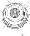
Figure 1 is a general top view of a valve closure; -
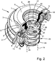
Figure 2 is another general view of the valve closure which is partially sectioned; -
Figure 3 is a general view of a known dispensing coupler with which the valve closure can be used; -
Figure 4 is an enlarged detail of a lower end of the dispensing coupler; -
Figure 5 is general view of the dispensing coupler engaged with the valve closure, both shown partially in axial section. - The valve closure V which is shown in
Fig.s 1 and2 comprises aclosure body 1 which is adapted to be fitted onto the neck of a beverage container such as a beer keg (not shown), which is typically formed by stretch blow moulding. All components of the valve closure may be moulded of polymeric materials (plastics) so that the closure is fully recyclable. An example of such a valve closure is described inEP 2 585 400 A1Fig. 2 , theclosure body 1 has an internally threadedcylindrical side wall 2 for screw-engagement with the neck of the container, and anannular end wall 3 which may include asealing ring 4 for sealing contact with the neck of the container. A short cylindrical connectingwall 5 extends upwardly from the inner edge of theend wall 3 to join an annulartop wall 6. An outer periphery of thetop wall 6 projects beyond the connectingwall 5 to form a connectingflange 7 which typically has three circumferentially-spacednotches 8 for engagement by a dispensing coupler of the kind described below. The inner periphery of thetop wall 6 forms anouter valve seat 9. Spaced inwardly of theside wall 2, anouter sleeve 10 is engaged with thetop wall 3 for reception within the neck of the container. - An
inner sleeve 12 forming an outer valve member includes aresilient ring seal 14 and is spring-loaded by anouter spring 15 located within theouter sleeve 10 to sealingly urge thering seal 14 against theouter valve seat 9. An upper end of theinner sleeve 12 forms ancylindrical socket 16 which is accessible through the annulartop wall 6. (SeeFig. 2 .) A lower end of thesocket 16 is defined by an inwardly directedshoulder 17 which provides aninner valve seat 18. A draw tube, indicated at 19, may be connected to the bottom end of thesleeve 12 for removing liquid from the container. Aninner valve member 20 is mounted inside the lower end of thesleeve 12. The valve member has a disc-shapedhead 21, formed withperipheral guide projections 22, which provides anannular valve face 23. Aninner spring 24, which is preferably integrally formed as part of thevalve member 20, urges theannular valve face 23 into sealing contact with theinner valve seat 18, the lower end of this spring bearing against the bottom of theinner sleeve 12. Thehead 21 of the valve member also includes a plurality ofupstanding projections 26 which are spaced inside theannular valve face 23 to project through theshoulder 17 towards thesocket 16. Theprojections 26 are circumferentially spaced apart by interveninggaps 27. It will be noted that the height of theprojections 26 measured axially of theinner sleeve 12 is less than the axial length of theshoulder 17 at the lower end of thesocket 16. At least three suchupstanding projections 26 are preferred to ensure that the valve member is not likely to tilt and jam during opening. - To dispense a liquid product from the container the
valve member 6 is engaged by a known dispensingcoupler 30 of the kind which is shown inFig.s 3 and 4 . The dispensing coupler includes ahousing 39 with agas inlet port 40. The coupler can be connected to a suitable valve closure by means of a bayonet fitting 41 formed with threeinternal flanges 42. Atubular probe 43 with acentral bore 44 is received within thehousing 39, such that the probe can be axially moved within the housing by means of apivotable handle 45. The proximal end of theprobe 43 which is remote from the valve closure in use, forms a liquid dispensing port. As can be seen inFig. 4 , the distal end of theprobe 43 has anannular end face 46, and carries a circumferentially-extendingring seal 47 which, when the coupler is connected with a valve closure, forms a fluid seal with the closure enabling liquid to flow out of the container through thebore 44. Between thering seal 47 and theend face 46 the probe has acircumferential locking recess 48 which is intended to receive locking fingers on a detachable closing element incorporated in another form of valve closure. The lockingrecess 48 is configured to lock onto the fingers in use, with opposing upper and lower faces 48.1 and 48.2. It will be noted that the upper face 48.1 is wide than the lower face 48.2 to project radially outwards beyond the lower face. - To dispense liquid from the container the bayonet fitting 41 is engaged with the annular
top wall 6 of the present valve closure - seeFig. 5 . Thehandle 45 is then pivoted to advance theprobe 43 into thesocket 16 of theinner sleeve 12 wherein thering seal 47 makes sealing contact with the socket. As the probe advances further into the socket the distal end face 46 contacts theprojections 26 urging thevalve head 21 to move out of contact with theinner valve seat 18 against the action of theinner spring 24. Theprojections 26 do not enter the liquid flow path within thecentral bore 44, thus maintaining an unrestricted flow path through the bore. At the same time, the upper face 48.1 of the lockingrecess 48 engages the top of theshoulder 17 of theinner sleeve 12. The downward force of the probe acting on theinner sleeve 12 thus causes thesleeve 12 to move against the upward action of theouter spring 15, moving thering seal 14 away from theouter valve seat 9. - The opening of the valve closure by the dispensing
coupler 30 thus opens up separate gas and liquid flow paths through the valve closure. Pressurised gas is fed into the container through thegas inlet port 40, along the outside of theprobe 43, between thering seal 14 and theouter valve seat 9, entering the container through the lower end of theouter sleeve 10. Liquid simultaneously flows out of the container through thedraw tube 19, flowing between thevalve head 21 and theinner valve seat 18 and passing into theprobe 43 through the gaps between theprojections 26. When dispensing is finished the dispensing coupler is disconnected, so that theinner sleeve 12 and thevalve member 20 both return to their sealing positions, holding the internal gas pressure within the container along with any remaining liquid. - The present valve closure can be used with existing dispensing couplers intended to operate S, D and M type closures as well as couplers of the kind described which are intended to engage the locking fingers of a closing element. Reliable connection, dispensing, and closing of the valve, along with improved liquid flow characteristics, can be obtained with the present valve closure. Similarly, the dispensing coupler can be used with the present valve closure, or those with a detachable closing element, without modification.
- In bag-in-keg containers the liquid product is held within an inner flexible bag formed of a thin impermeable non-structural membrane which is sealingly joined, e.g. by welding, to an adapter which is connected to the
outer sleeve 10. During dispensing the pressurised gas is fed into the space between the flexible bag and the outer container. - Whilst the above description places emphasis on the areas which are believed to be new and addresses specific problems which have been identified, it is intended that the features disclosed herein may be used in any combination which is capable of providing a new and useful advance in the art.
Claims (12)
- A valve closure and a dispensing coupler configured to operate the valve closure:-the valve closure having:- an inner sleeve (12) which includes a socket (16) and an annular inner valve seat (18);- a valve member (21) having an annular sealing face (23) co-operable with the inner valve seat (18);- spring means (24) urging the valve member (21) against the inner valve seat (18);- wherein the valve member (21) incorporates a plurality of projections (26) spaced radially inwards from the annular sealing face (23) and projecting towards the socket (16);the dispensing coupler having:- a housing (39);- a tubular probe (43) slidably received within the housing, the tubular probe having a central bore (44);- wherein a distal end of the tubular probe (43) has an end face (46), a circumferentially-extending ring seal (47), and a circumferential locking recess (48) disposed between the ring seal (47) and the end face (46) to engage a detachable closing element;characterised in thatthe circumferential locking recess (48) has opposing upper and lower faces (48.1 and 48.2).
- A valve closure and a dispensing coupler according to claim 1 wherein the valve member (21) incorporates at least three projections (26).
- A valve closure and a dispensing coupler according to claim 1 wherein a lower end of the socket (16) is defined by an inwardly directed shoulder (17) which provides the inner valve seat (18).
- A valve closure and a dispensing coupler according to claim 3 wherein the height of the projections (26) measured axially of the inner sleeve (12) is less than the axial length of the shoulder (17) at the lower end of the socket (16).
- A valve closure and a dispensing coupler according to claim 1 wherein the inner sleeve (12) is disposed within an outer sleeve (10) adapted (2, 4) to engage the neck of a container.
- A valve closure and a dispensing coupler according to claim 5 wherein the outer sleeve (10) is connected to an annular top wall (6) forming an outer valve seat (9).
- A valve closure and a dispensing coupler according to claim 6 wherein the inner sleeve (12) is provided with a ring seal (14) co-operable with the outer valve seat (9).
- A valve closure and a dispensing coupler according to claim 6 wherein outer spring means (15) urges the inner sleeve (12) towards the outer valve seat (9).
- A valve closure and a dispensing coupler according to claim 6 wherein an outer periphery (7) of the annular top wall (6) projects radially outwards and has a plurality of circumferential notches (8).
- A valve closure and a dispensing coupler according to claim 1 wherein the upper face (48.1) of the locking recess (48) is wider than the lower face (48.2) and projects radially outwards beyond the lower face.
- A valve closure and a dispensing coupler according to claim 1 wherein the housing (39) has a gas inlet port (40).
- A valve closure and a dispensing coupler according to claim 1 wherein the dispensing coupler has a bayonet fitting (41) to engage the valve closure.
Applications Claiming Priority (2)
| Application Number | Priority Date | Filing Date | Title |
|---|---|---|---|
| GB1900002.5A GB2580335B (en) | 2019-01-01 | 2019-01-01 | Valve closure with concentric spring-loaded moving valve members |
| PCT/GB2019/053709 WO2020141320A1 (en) | 2019-01-01 | 2019-12-31 | Valve closure with concentric spring-loaded moving valve members, the internal valve member having axial protrusions |
Publications (2)
| Publication Number | Publication Date |
|---|---|
| EP3906211A1 EP3906211A1 (en) | 2021-11-10 |
| EP3906211B1 true EP3906211B1 (en) | 2022-12-21 |
Family
ID=65364668
Family Applications (1)
| Application Number | Title | Priority Date | Filing Date |
|---|---|---|---|
| EP19848937.9A Active EP3906211B1 (en) | 2019-01-01 | 2019-12-31 | Valve closure with concentric spring-loaded moving valve members, the internal valve member having axial protrusions |
Country Status (4)
| Country | Link |
|---|---|
| US (1) | US11524885B2 (en) |
| EP (1) | EP3906211B1 (en) |
| GB (1) | GB2580335B (en) |
| WO (1) | WO2020141320A1 (en) |
Families Citing this family (1)
| Publication number | Priority date | Publication date | Assignee | Title |
|---|---|---|---|---|
| GB2609930A (en) | 2021-08-17 | 2023-02-22 | Polykeg S R L | Compact beverage dispenser |
Citations (1)
| Publication number | Priority date | Publication date | Assignee | Title |
|---|---|---|---|---|
| US86196A (en) * | 1869-01-26 | Improvement in atttomatic plugs por barrel s |
Family Cites Families (11)
| Publication number | Priority date | Publication date | Assignee | Title |
|---|---|---|---|---|
| US3353724A (en) * | 1965-10-22 | 1967-11-21 | Mack S Johnston | Beer tapping device |
| US3439844A (en) * | 1965-10-22 | 1969-04-22 | Johnston Enterprises Inc | Tapping device for beer kegs and the like |
| US3422448A (en) * | 1966-10-18 | 1969-01-14 | Johnston Enterprises Inc | Tapping device for beer kegs and the like |
| US3591058A (en) * | 1968-11-05 | 1971-07-06 | Republic Corp | Tapping device for beer kegs and the like |
| US3599843A (en) * | 1969-04-14 | 1971-08-17 | Republic Corp | Keg tapping device |
| US4180189A (en) * | 1978-01-11 | 1979-12-25 | Vending Components, Inc. | Single valve dispensing tube |
| NL1009812C2 (en) * | 1998-08-05 | 2000-02-08 | Euro Maintenance Lease Prod Bv | Shut-off valve for a container. |
| GB2446396A (en) | 2007-02-12 | 2008-08-13 | Inbev Sa | Valve assembly for a beer keg |
| PT2014608T (en) * | 2007-07-10 | 2016-12-01 | Eurokeg Bv | Dispense head |
| GB2481577A (en) | 2010-06-24 | 2012-01-04 | Silvia Romana Marabini | Valve closure for containers such as beer kegs |
| IT201800004912A1 (en) * | 2018-04-27 | 2019-10-27 | SPRING DEVICE AND VALVE UNIT FOR A BEVERAGE CONTAINER |
-
2019
- 2019-01-01 GB GB1900002.5A patent/GB2580335B/en active Active
- 2019-12-31 US US17/418,835 patent/US11524885B2/en active Active
- 2019-12-31 EP EP19848937.9A patent/EP3906211B1/en active Active
- 2019-12-31 WO PCT/GB2019/053709 patent/WO2020141320A1/en unknown
Patent Citations (1)
| Publication number | Priority date | Publication date | Assignee | Title |
|---|---|---|---|---|
| US86196A (en) * | 1869-01-26 | Improvement in atttomatic plugs por barrel s |
Also Published As
| Publication number | Publication date |
|---|---|
| US11524885B2 (en) | 2022-12-13 |
| GB2580335B (en) | 2022-12-14 |
| EP3906211A1 (en) | 2021-11-10 |
| GB2580335A (en) | 2020-07-22 |
| GB201900002D0 (en) | 2019-02-13 |
| WO2020141320A4 (en) | 2020-08-06 |
| US20220073333A1 (en) | 2022-03-10 |
| WO2020141320A1 (en) | 2020-07-09 |
Similar Documents
| Publication | Publication Date | Title |
|---|---|---|
| EP2726398B1 (en) | Beverage dispensing system | |
| US9643829B2 (en) | Keg closure with safety mechanism | |
| JP2009083938A (en) | Tapping rod | |
| GB2481577A (en) | Valve closure for containers such as beer kegs | |
| CN113165859A (en) | Kit for dispensing a beverage through a dispensing tube comprising a dispensing valve | |
| EP3906211B1 (en) | Valve closure with concentric spring-loaded moving valve members, the internal valve member having axial protrusions | |
| WO2004063087A1 (en) | Keg filling and dispensing system with valve assembly fitted from exterior | |
| WO2012062874A1 (en) | Keg closure with safety mechanism | |
| EP3877321B1 (en) | Bag-in-keg container with valve sealing lip | |
| US9475684B2 (en) | Container, and method for filling a container | |
| EP3877324B1 (en) | Bag-in-keg container with fixed pressure pressure relief valve | |
| WO2000020326A1 (en) | Closure valves | |
| WO1991000240A1 (en) | A valve assembly | |
| US20230035704A1 (en) | Sealing Unit for a Container | |
| AU2004205049B2 (en) | Keg filling and dispensing system with valve assembly fitted from exterior | |
| JPH04279494A (en) | Bottling device |
Legal Events
| Date | Code | Title | Description |
|---|---|---|---|
| STAA | Information on the status of an ep patent application or granted ep patent |
Free format text: STATUS: UNKNOWN |
|
| STAA | Information on the status of an ep patent application or granted ep patent |
Free format text: STATUS: THE INTERNATIONAL PUBLICATION HAS BEEN MADE |
|
| PUAI | Public reference made under article 153(3) epc to a published international application that has entered the european phase |
Free format text: ORIGINAL CODE: 0009012 |
|
| STAA | Information on the status of an ep patent application or granted ep patent |
Free format text: STATUS: REQUEST FOR EXAMINATION WAS MADE |
|
| 17P | Request for examination filed |
Effective date: 20210720 |
|
| AK | Designated contracting states |
Kind code of ref document: A1 Designated state(s): AL AT BE BG CH CY CZ DE DK EE ES FI FR GB GR HR HU IE IS IT LI LT LU LV MC MK MT NL NO PL PT RO RS SE SI SK SM TR |
|
| DAV | Request for validation of the european patent (deleted) | ||
| DAX | Request for extension of the european patent (deleted) | ||
| GRAP | Despatch of communication of intention to grant a patent |
Free format text: ORIGINAL CODE: EPIDOSNIGR1 |
|
| STAA | Information on the status of an ep patent application or granted ep patent |
Free format text: STATUS: GRANT OF PATENT IS INTENDED |
|
| INTG | Intention to grant announced |
Effective date: 20220725 |
|
| GRAS | Grant fee paid |
Free format text: ORIGINAL CODE: EPIDOSNIGR3 |
|
| GRAA | (expected) grant |
Free format text: ORIGINAL CODE: 0009210 |
|
| STAA | Information on the status of an ep patent application or granted ep patent |
Free format text: STATUS: THE PATENT HAS BEEN GRANTED |
|
| AK | Designated contracting states |
Kind code of ref document: B1 Designated state(s): AL AT BE BG CH CY CZ DE DK EE ES FI FR GB GR HR HU IE IS IT LI LT LU LV MC MK MT NL NO PL PT RO RS SE SI SK SM TR |
|
| REG | Reference to a national code |
Ref country code: GB Ref legal event code: FG4D |
|
| RIN1 | Information on inventor provided before grant (corrected) |
Inventor name: SONZOGNI, SERGIO Inventor name: WALTON, PHILIP ANDREW |
|
| REG | Reference to a national code |
Ref country code: DE Ref legal event code: R096 Ref document number: 602019023521 Country of ref document: DE |
|
| REG | Reference to a national code |
Ref country code: CH Ref legal event code: EP |
|
| REG | Reference to a national code |
Ref country code: AT Ref legal event code: REF Ref document number: 1538976 Country of ref document: AT Kind code of ref document: T Effective date: 20230115 |
|
| REG | Reference to a national code |
Ref country code: IE Ref legal event code: FG4D |
|
| REG | Reference to a national code |
Ref country code: LT Ref legal event code: MG9D |
|
| REG | Reference to a national code |
Ref country code: NL Ref legal event code: MP Effective date: 20221221 |
|
| PG25 | Lapsed in a contracting state [announced via postgrant information from national office to epo] |
Ref country code: SE Free format text: LAPSE BECAUSE OF FAILURE TO SUBMIT A TRANSLATION OF THE DESCRIPTION OR TO PAY THE FEE WITHIN THE PRESCRIBED TIME-LIMIT Effective date: 20221221 Ref country code: NO Free format text: LAPSE BECAUSE OF FAILURE TO SUBMIT A TRANSLATION OF THE DESCRIPTION OR TO PAY THE FEE WITHIN THE PRESCRIBED TIME-LIMIT Effective date: 20230321 Ref country code: LT Free format text: LAPSE BECAUSE OF FAILURE TO SUBMIT A TRANSLATION OF THE DESCRIPTION OR TO PAY THE FEE WITHIN THE PRESCRIBED TIME-LIMIT Effective date: 20221221 Ref country code: FI Free format text: LAPSE BECAUSE OF FAILURE TO SUBMIT A TRANSLATION OF THE DESCRIPTION OR TO PAY THE FEE WITHIN THE PRESCRIBED TIME-LIMIT Effective date: 20221221 |
|
| REG | Reference to a national code |
Ref country code: AT Ref legal event code: MK05 Ref document number: 1538976 Country of ref document: AT Kind code of ref document: T Effective date: 20221221 |
|
| PG25 | Lapsed in a contracting state [announced via postgrant information from national office to epo] |
Ref country code: RS Free format text: LAPSE BECAUSE OF FAILURE TO SUBMIT A TRANSLATION OF THE DESCRIPTION OR TO PAY THE FEE WITHIN THE PRESCRIBED TIME-LIMIT Effective date: 20221221 Ref country code: LV Free format text: LAPSE BECAUSE OF FAILURE TO SUBMIT A TRANSLATION OF THE DESCRIPTION OR TO PAY THE FEE WITHIN THE PRESCRIBED TIME-LIMIT Effective date: 20221221 Ref country code: HR Free format text: LAPSE BECAUSE OF FAILURE TO SUBMIT A TRANSLATION OF THE DESCRIPTION OR TO PAY THE FEE WITHIN THE PRESCRIBED TIME-LIMIT Effective date: 20221221 Ref country code: GR Free format text: LAPSE BECAUSE OF FAILURE TO SUBMIT A TRANSLATION OF THE DESCRIPTION OR TO PAY THE FEE WITHIN THE PRESCRIBED TIME-LIMIT Effective date: 20230322 |
|
| PG25 | Lapsed in a contracting state [announced via postgrant information from national office to epo] |
Ref country code: NL Free format text: LAPSE BECAUSE OF FAILURE TO SUBMIT A TRANSLATION OF THE DESCRIPTION OR TO PAY THE FEE WITHIN THE PRESCRIBED TIME-LIMIT Effective date: 20221221 |
|
| REG | Reference to a national code |
Ref country code: DE Ref legal event code: R119 Ref document number: 602019023521 Country of ref document: DE |
|
| PG25 | Lapsed in a contracting state [announced via postgrant information from national office to epo] |
Ref country code: SM Free format text: LAPSE BECAUSE OF FAILURE TO SUBMIT A TRANSLATION OF THE DESCRIPTION OR TO PAY THE FEE WITHIN THE PRESCRIBED TIME-LIMIT Effective date: 20221221 Ref country code: RO Free format text: LAPSE BECAUSE OF FAILURE TO SUBMIT A TRANSLATION OF THE DESCRIPTION OR TO PAY THE FEE WITHIN THE PRESCRIBED TIME-LIMIT Effective date: 20221221 Ref country code: PT Free format text: LAPSE BECAUSE OF FAILURE TO SUBMIT A TRANSLATION OF THE DESCRIPTION OR TO PAY THE FEE WITHIN THE PRESCRIBED TIME-LIMIT Effective date: 20230421 Ref country code: IT Free format text: LAPSE BECAUSE OF NON-PAYMENT OF DUE FEES Effective date: 20221231 Ref country code: ES Free format text: LAPSE BECAUSE OF FAILURE TO SUBMIT A TRANSLATION OF THE DESCRIPTION OR TO PAY THE FEE WITHIN THE PRESCRIBED TIME-LIMIT Effective date: 20221221 Ref country code: EE Free format text: LAPSE BECAUSE OF FAILURE TO SUBMIT A TRANSLATION OF THE DESCRIPTION OR TO PAY THE FEE WITHIN THE PRESCRIBED TIME-LIMIT Effective date: 20221221 Ref country code: CZ Free format text: LAPSE BECAUSE OF FAILURE TO SUBMIT A TRANSLATION OF THE DESCRIPTION OR TO PAY THE FEE WITHIN THE PRESCRIBED TIME-LIMIT Effective date: 20221221 Ref country code: AT Free format text: LAPSE BECAUSE OF FAILURE TO SUBMIT A TRANSLATION OF THE DESCRIPTION OR TO PAY THE FEE WITHIN THE PRESCRIBED TIME-LIMIT Effective date: 20221221 |
|
| REG | Reference to a national code |
Ref country code: CH Ref legal event code: PL |
|
| REG | Reference to a national code |
Ref country code: BE Ref legal event code: MM Effective date: 20221231 |
|
| PG25 | Lapsed in a contracting state [announced via postgrant information from national office to epo] |
Ref country code: SK Free format text: LAPSE BECAUSE OF FAILURE TO SUBMIT A TRANSLATION OF THE DESCRIPTION OR TO PAY THE FEE WITHIN THE PRESCRIBED TIME-LIMIT Effective date: 20221221 Ref country code: PL Free format text: LAPSE BECAUSE OF FAILURE TO SUBMIT A TRANSLATION OF THE DESCRIPTION OR TO PAY THE FEE WITHIN THE PRESCRIBED TIME-LIMIT Effective date: 20221221 Ref country code: LU Free format text: LAPSE BECAUSE OF NON-PAYMENT OF DUE FEES Effective date: 20221231 Ref country code: IS Free format text: LAPSE BECAUSE OF FAILURE TO SUBMIT A TRANSLATION OF THE DESCRIPTION OR TO PAY THE FEE WITHIN THE PRESCRIBED TIME-LIMIT Effective date: 20230421 Ref country code: AL Free format text: LAPSE BECAUSE OF FAILURE TO SUBMIT A TRANSLATION OF THE DESCRIPTION OR TO PAY THE FEE WITHIN THE PRESCRIBED TIME-LIMIT Effective date: 20221221 |
|
| PG25 | Lapsed in a contracting state [announced via postgrant information from national office to epo] |
Ref country code: MC Free format text: LAPSE BECAUSE OF FAILURE TO SUBMIT A TRANSLATION OF THE DESCRIPTION OR TO PAY THE FEE WITHIN THE PRESCRIBED TIME-LIMIT Effective date: 20221221 |
|
| PLBE | No opposition filed within time limit |
Free format text: ORIGINAL CODE: 0009261 |
|
| STAA | Information on the status of an ep patent application or granted ep patent |
Free format text: STATUS: NO OPPOSITION FILED WITHIN TIME LIMIT |
|
| PG25 | Lapsed in a contracting state [announced via postgrant information from national office to epo] |
Ref country code: LI Free format text: LAPSE BECAUSE OF NON-PAYMENT OF DUE FEES Effective date: 20221231 Ref country code: IE Free format text: LAPSE BECAUSE OF NON-PAYMENT OF DUE FEES Effective date: 20221231 Ref country code: DK Free format text: LAPSE BECAUSE OF FAILURE TO SUBMIT A TRANSLATION OF THE DESCRIPTION OR TO PAY THE FEE WITHIN THE PRESCRIBED TIME-LIMIT Effective date: 20221221 Ref country code: DE Free format text: LAPSE BECAUSE OF NON-PAYMENT OF DUE FEES Effective date: 20230701 Ref country code: CH Free format text: LAPSE BECAUSE OF NON-PAYMENT OF DUE FEES Effective date: 20221231 |
|
| 26N | No opposition filed |
Effective date: 20230922 |
|
| PG25 | Lapsed in a contracting state [announced via postgrant information from national office to epo] |
Ref country code: BE Free format text: LAPSE BECAUSE OF NON-PAYMENT OF DUE FEES Effective date: 20221231 |
|
| PG25 | Lapsed in a contracting state [announced via postgrant information from national office to epo] |
Ref country code: SI Free format text: LAPSE BECAUSE OF FAILURE TO SUBMIT A TRANSLATION OF THE DESCRIPTION OR TO PAY THE FEE WITHIN THE PRESCRIBED TIME-LIMIT Effective date: 20221221 Ref country code: FR Free format text: LAPSE BECAUSE OF NON-PAYMENT OF DUE FEES Effective date: 20230221 |
|
| PGFP | Annual fee paid to national office [announced via postgrant information from national office to epo] |
Ref country code: IT Payment date: 20231228 Year of fee payment: 5 |