EP3906115B1 - Ewod-kartuschenpositionserfassung beim andocken in ein ewod-instrument - Google Patents
Ewod-kartuschenpositionserfassung beim andocken in ein ewod-instrument Download PDFInfo
- Publication number
- EP3906115B1 EP3906115B1 EP20712407.4A EP20712407A EP3906115B1 EP 3906115 B1 EP3906115 B1 EP 3906115B1 EP 20712407 A EP20712407 A EP 20712407A EP 3906115 B1 EP3906115 B1 EP 3906115B1
- Authority
- EP
- European Patent Office
- Prior art keywords
- locator
- array
- ewod
- microfluidic
- cartridge
- Prior art date
- Legal status (The legal status is an assumption and is not a legal conclusion. Google has not performed a legal analysis and makes no representation as to the accuracy of the status listed.)
- Active
Links
Images





Classifications
-
- B—PERFORMING OPERATIONS; TRANSPORTING
- B01—PHYSICAL OR CHEMICAL PROCESSES OR APPARATUS IN GENERAL
- B01L—CHEMICAL OR PHYSICAL LABORATORY APPARATUS FOR GENERAL USE
- B01L3/00—Containers or dishes for laboratory use, e.g. laboratory glassware; Droppers
- B01L3/50—Containers for the purpose of retaining a material to be analysed, e.g. test tubes
- B01L3/502—Containers for the purpose of retaining a material to be analysed, e.g. test tubes with fluid transport, e.g. in multi-compartment structures
- B01L3/5027—Containers for the purpose of retaining a material to be analysed, e.g. test tubes with fluid transport, e.g. in multi-compartment structures by integrated microfluidic structures, i.e. dimensions of channels and chambers are such that surface tension forces are important, e.g. lab-on-a-chip
- B01L3/502769—Containers for the purpose of retaining a material to be analysed, e.g. test tubes with fluid transport, e.g. in multi-compartment structures by integrated microfluidic structures, i.e. dimensions of channels and chambers are such that surface tension forces are important, e.g. lab-on-a-chip characterised by multiphase flow arrangements
- B01L3/502784—Containers for the purpose of retaining a material to be analysed, e.g. test tubes with fluid transport, e.g. in multi-compartment structures by integrated microfluidic structures, i.e. dimensions of channels and chambers are such that surface tension forces are important, e.g. lab-on-a-chip characterised by multiphase flow arrangements specially adapted for droplet or plug flow, e.g. digital microfluidics
- B01L3/502792—Containers for the purpose of retaining a material to be analysed, e.g. test tubes with fluid transport, e.g. in multi-compartment structures by integrated microfluidic structures, i.e. dimensions of channels and chambers are such that surface tension forces are important, e.g. lab-on-a-chip characterised by multiphase flow arrangements specially adapted for droplet or plug flow, e.g. digital microfluidics for moving individual droplets on a plate, e.g. by locally altering surface tension
-
- G—PHYSICS
- G02—OPTICS
- G02B—OPTICAL ELEMENTS, SYSTEMS OR APPARATUS
- G02B26/00—Optical devices or arrangements for the control of light using movable or deformable optical elements
- G02B26/004—Optical devices or arrangements for the control of light using movable or deformable optical elements based on a displacement or a deformation of a fluid
- G02B26/005—Optical devices or arrangements for the control of light using movable or deformable optical elements based on a displacement or a deformation of a fluid based on electrowetting
-
- B—PERFORMING OPERATIONS; TRANSPORTING
- B01—PHYSICAL OR CHEMICAL PROCESSES OR APPARATUS IN GENERAL
- B01L—CHEMICAL OR PHYSICAL LABORATORY APPARATUS FOR GENERAL USE
- B01L2200/00—Solutions for specific problems relating to chemical or physical laboratory apparatus
- B01L2200/02—Adapting objects or devices to another
- B01L2200/025—Align devices or objects to ensure defined positions relative to each other
-
- B—PERFORMING OPERATIONS; TRANSPORTING
- B01—PHYSICAL OR CHEMICAL PROCESSES OR APPARATUS IN GENERAL
- B01L—CHEMICAL OR PHYSICAL LABORATORY APPARATUS FOR GENERAL USE
- B01L2200/00—Solutions for specific problems relating to chemical or physical laboratory apparatus
- B01L2200/06—Fluid handling related problems
- B01L2200/061—Counting droplets
-
- B—PERFORMING OPERATIONS; TRANSPORTING
- B01—PHYSICAL OR CHEMICAL PROCESSES OR APPARATUS IN GENERAL
- B01L—CHEMICAL OR PHYSICAL LABORATORY APPARATUS FOR GENERAL USE
- B01L2200/00—Solutions for specific problems relating to chemical or physical laboratory apparatus
- B01L2200/06—Fluid handling related problems
- B01L2200/0673—Handling of plugs of fluid surrounded by immiscible fluid
-
- B—PERFORMING OPERATIONS; TRANSPORTING
- B01—PHYSICAL OR CHEMICAL PROCESSES OR APPARATUS IN GENERAL
- B01L—CHEMICAL OR PHYSICAL LABORATORY APPARATUS FOR GENERAL USE
- B01L2300/00—Additional constructional details
- B01L2300/06—Auxiliary integrated devices, integrated components
- B01L2300/0627—Sensor or part of a sensor is integrated
- B01L2300/0645—Electrodes
-
- B—PERFORMING OPERATIONS; TRANSPORTING
- B01—PHYSICAL OR CHEMICAL PROCESSES OR APPARATUS IN GENERAL
- B01L—CHEMICAL OR PHYSICAL LABORATORY APPARATUS FOR GENERAL USE
- B01L2300/00—Additional constructional details
- B01L2300/06—Auxiliary integrated devices, integrated components
- B01L2300/0627—Sensor or part of a sensor is integrated
- B01L2300/0663—Whole sensors
-
- B—PERFORMING OPERATIONS; TRANSPORTING
- B01—PHYSICAL OR CHEMICAL PROCESSES OR APPARATUS IN GENERAL
- B01L—CHEMICAL OR PHYSICAL LABORATORY APPARATUS FOR GENERAL USE
- B01L2300/00—Additional constructional details
- B01L2300/08—Geometry, shape and general structure
- B01L2300/0809—Geometry, shape and general structure rectangular shaped
- B01L2300/0819—Microarrays; Biochips
-
- B—PERFORMING OPERATIONS; TRANSPORTING
- B01—PHYSICAL OR CHEMICAL PROCESSES OR APPARATUS IN GENERAL
- B01L—CHEMICAL OR PHYSICAL LABORATORY APPARATUS FOR GENERAL USE
- B01L2400/00—Moving or stopping fluids
- B01L2400/04—Moving fluids with specific forces or mechanical means
- B01L2400/0403—Moving fluids with specific forces or mechanical means specific forces
- B01L2400/0415—Moving fluids with specific forces or mechanical means specific forces electrical forces, e.g. electrokinetic
- B01L2400/0427—Electrowetting
Definitions
- the present invention relates to droplet microfluidic devices, and more specifically to Active Matrix Electrowetting-On-Dielectric (AM-EWOD) devices, and to methods of AM-EWOD operation to adjust a reaction protocol or script to account for misalignment of an AM-EWOD cartridge relative to an AM-EWOD instrument.
- AM-EWOD Active Matrix Electrowetting-On-Dielectric
- Electrowetting on dielectric is a well-known technique for manipulating droplets of fluid by application of an electric field.
- Active Matrix EWOD refers to implementation of EWOD in an active matrix array incorporating transistors, for example by using thin film transistors (TFTs). It is thus a candidate technology for digital microfluidics for lab-on-a-chip technology. An introduction to the basic principles of the technology can be found in " Digital microfluidics: is a true lab-on-a-chip possible?", R.B. Fair, Microfluid Nanofluid (2007) 3:245-281 ).
- Fig. 1 is a drawing depicting an exemplary EWOD based microfluidic system.
- the microfluidic system includes a reader 32 and a cartridge 34.
- the cartridge 34 may contain a microfluidic device, such as an AM-EWOD device 36, as well as (not shown) fluid input ports into the device and an electrical connection as are conventional.
- the fluid input ports may perform the function of inputting fluid into the AM-EWOD device 36 and generating droplets within the device, for example by dispensing from input reservoirs as controlled by electrowetting.
- the microfluidic device includes an electrode array configured to receive the inputted fluid droplets.
- the microfluidic system further may include a control system configured to control actuation voltages applied to the electrode array of the microfluidic device to perform manipulation operations to the fluid droplets.
- the reader 32 may contain such a control system configured as control electronics 38 and a storage device 40 that may store any application software and any data associated with the system.
- the control electronics 38 may include suitable circuitry and/or processing devices that are configured to carry out various control operations relating to control of the AM-EWOD device 36, such as a CPU, microcontroller or microprocessor.
- an external sensor module 35 is provided for sensor droplet properties.
- optical sensors as are known in the art may be employed as external sensors for sensing droplet properties, which may be incorporated into a probe that can be located in proximity to the EWOD device. Suitable optical sensors include camera devices, light sensors, charged coupled devices (CCD) and similar image sensors, and the like.
- CCD charged coupled devices
- a sensor additionally or alternatively may be configured as internal sensor circuitry incorporated as part of the drive circuitry in each array element. Such sensor circuitry may sense droplet properties by the detection of an electrical property at the array element, such as impedance or capacitance.
- Fig. 2 is a drawing depicting additional details of the exemplary AM-EWOD device 36 in a perspective view.
- the AM-EWOD device 36 has a lower substrate assembly 44 with thin film electronics 46 disposed upon the lower substrate assembly 44.
- the thin film electronics 46 are arranged to drive array element electrodes 48.
- a plurality of array element electrodes 48 are arranged in an electrode or element two-dimensional array 50, having N rows by M columns of array elements where N and M may be any integer.
- a liquid droplet 52 which may include any polar liquid and which typically may be aqueous, is enclosed between the lower substrate 44 and a top substrate 54 separated by a spacer 56, although it will be appreciated that multiple liquid droplets 52 can be present.
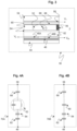
- Fig. 3 is a drawing depicting a cross section through some of the array elements of the exemplary AM-EWOD 36 device of Fig. 2 .
- the device includes a pair of the array element electrodes 48A and 48B that are shown in cross section that may be utilized in the electrode or element array 50 of the AM-EWOD device 36 of Fig. 3 .
- the AM-EWOD device 36 further incorporates the thin-film electronics 46 disposed on the lower substrate 44, which is separated from the upper substrate 54 by the spacer 56.
- the uppermost layer of the lower substrate 44 (which may be considered a part of the thin film electronics layer 46) is patterned so that a plurality of the array element electrodes 48 (e.g. specific examples of array element electrodes are 48A and 48B in Fig. 3 ) are realized.
- the term element electrode 48 may be taken in what follows to refer both to the physical electrode structure 48 associated with a particular array element, and also to the node of an electrical circuit directly connected to this physical structure.
- a reference electrode 58 is shown in Fig. 3 disposed upon the top substrate 54, but the reference electrode alternatively may be disposed upon the lower substrate 44 to realize an in-plane reference electrode geometry.
- the term reference electrode 58 may also be taken in what follows to refer to both or either of the physical electrode structure and also to the node of an electrical circuit directly connected to this physical structure.
- a non-polar fluid 60 (e.g. oil) may be used to occupy the volume not occupied by the liquid droplet 52.
- An insulator layer 62 may be disposed upon the lower substrate 44 that separates the conductive element electrodes 48A and 48B from a first hydrophobic coating 64 upon which the liquid droplet 52 sits with a contact angle 66 represented by ⁇ .
- the hydrophobic coating is formed from a hydrophobic material (commonly, but not necessarily, a fluoropolymer).
- On the top substrate 54 is a second hydrophobic coating 68 with which the liquid droplet 52 may come into contact.
- the reference electrode 58 is interposed between the top substrate 54 and the second hydrophobic coating 68.
- EW drive voltages may be externally applied to different electrodes (e.g. reference electrode 58, element electrodes 48A and 48B, respectively).
- electrodes e.g. reference electrode 58, element electrodes 48A and 48B, respectively.
- EW drive voltages e.g. V 0 and V 00
- element electrodes e.g. 48A and 48B
- Fig. 4A shows a circuit representation of the electrical load 70A between the element electrode 48 and the reference electrode 58 in the case when a liquid droplet 52 is present.
- the liquid droplet 52 can usually be modeled as a resistor and capacitor in parallel.
- the resistance of the droplet will be relatively low (e.g. if the droplet contains ions) and the capacitance of the droplet will be relatively high (e.g. because the relative permittivity of polar liquids is relatively high, e.g. ⁇ 80 if the liquid droplet is aqueous).
- the droplet resistance is relatively small, such that at the frequencies of interest for electrowetting, the liquid droplet 52 may function effectively as an electrical short circuit.
- the hydrophobic coatings 64 and 68 have electrical characteristics that may be modelled as capacitors, and the insulator 62 may also be modelled as a capacitor.
- the overall impedance between the element electrode 48 and the reference electrode 58 may be approximated by a capacitor whose value is typically dominated by the contribution of the insulator 62 and hydrophobic coatings 64 and 68 contributions, and which for typical layer thicknesses and materials may be on the order of a pico-Farad in value.
- Fig. 4B shows a circuit representation of the electrical load 70B between the element electrode 48 and the reference electrode 58 in the case when no liquid droplet is present.
- the liquid droplet components are replaced by a capacitor representing the capacitance of the non-polar fluid 60 which occupies the space between the top and lower substrates.
- the overall impedance between the element electrode 48 and the reference electrode 58 may be approximated by a capacitor whose value is dominated by the capacitance of the non-polar fluid and which is typically small, on the order of femto-Farads.
- the electrical load 70A/70B overall functions in effect as a capacitor, whose value depends on whether a liquid droplet 52 is present or not at a given element electrode 48.
- the capacitance is relatively high (typically of order pico-Farads), whereas if there is no liquid droplet present the capacitance is low (typically of order femto-Farads). If a droplet partially covers a given electrode 48 then the capacitance may approximately represent the extent of coverage of the element electrode 48 by the liquid droplet 52.
- US 7,163,612 (Sterling et al., issued Jan. 16, 2007 ) describes how TFT based thin film electronics may be used to control the addressing of voltage pulses to an EWOD array by using circuit arrangements very similar to those employed in active matrix display technologies.
- the approach of US 7,163,612 may be termed "Active Matrix Electrowetting on Dielectric" (AM-EWOD).
- AM-EWOD Active Matrix Electrowetting on Dielectric
- Fig. 5 is a drawing depicting an exemplary arrangement of thin film electronics 46 in the exemplary AM-EWOD device 36 of Fig. 2 .
- the thin film electronics 46 is located upon the lower substrate 44.
- Each array element 51 of the array of elements 50 contains an array element circuit 72 for controlling the electrode potential of a corresponding element electrode 48.
- Integrated row driver 74 and column driver 76 circuits are also implemented in thin film electronics 46 to supply control signals to the array element circuit 72.
- the array element circuit 72 may also contain a sensor capability for detecting the presence or absence of a liquid droplet in the location of the array element.
- Integrated sensor row addressing 78 and column detection circuits 80 may further be implemented in thin film electronics for the addressing and readout of the sensor circuitry in each array element.
- a serial interface 82 may also be provided to process a serial input data stream and facilitate the programming of the required voltages to the element electrodes 48 in the array 50.
- a voltage supply interface 84 provides the corresponding supply voltages, top substrate drive voltages, and other requisite voltage inputs as further described herein.
- a number of connecting wires 86 between the lower substrate 44 and external control electronics, power supplies and any other components can be made relatively few, even for large array sizes.
- the serial data input may be partially parallelized. For example, if two data input lines are used the first may supply data for columns 1 to X/2, and the second for columns (1+X/2) to M with minor modifications to the column driver circuits 76. In this way the rate at which data can be programmed to the array is increased, which is a standard technique used in liquid crystal display driving circuitry.
- Fig. 6 is a drawing depicting an exemplary arrangement of the array element circuit 72 present in each array element 51, which may be used as part of the thin film electronics of Fig. 5 .
- the array element circuit 72 may contain an actuation circuit 88, having inputs ENABLE, DATA and ACTUATE, and an output which is connected to an element electrode 48.
- the array element circuit 72 also may contain a droplet sensing circuit 90, which may be in electrical communication with the element electrode 48.
- the read-out of the droplet sensing circuit 90 may be controlled by one or more addressing lines (e.g. RW) that may be common to elements in the same row of the array, and may also have one or more outputs, e.g. OUT, which may be common to all elements in the same column of the array.
- addressing lines e.g. RW
- the array element circuit 72 may typically perform the functions of:
- AM-EWOD devices having integrated actuation and sensing circuits are described, for example, in Applicant's commonly assigned patent documents as follows: US 8,653,832 (Hadwen et al., issued February 18, 2014 ); US 2018/0078934 (Hadwen et al., published March 22, 2018 ); US 2017/0076676 (Hadwen, published March 16, 2017 ); and US 8,173,000 (Hadwen et al., issued May 8, 2012 ).
- the enhanced method of operation described in the current application may be employed in connection with any suitable array element circuitry 72 including any suitable integrated impedance sensing circuitry 90.
- sensing of a remote object such as a stylus can be performed using an active matrix TFT array, as described for example in US 2014/0168539 (Kim et al., published June 19, 2014 ).
- active matrix TFT array as described for example in US 2014/0168539 (Kim et al., published June 19, 2014 ).
- Such principles have not been applied in the context of a microfluidic device, such as an AM-EWOD device in particular.
- a disposable AM-EWOD cartridge that includes the element array and thin film electronics is inserted into a broader AM-EWOD instrument that controls and supplies actuation voltages, reads out sensor information and related output signals, inputs and extracts fluid, and provides the operator interface. It is of significant importance, therefore, that the AM-EWOD cartridge be properly docked into and aligned with the AM-EWOD instrument at a position optimized for the desired reaction protocols or scripts.
- the AM-EWOD instrument and/or AM-EWOD cartridge typically include docking features, but such features may only provide a relatively gross positioning of the AM-EWOD cartridge relative to pertinent AM-EWOD instrument components.
- a high precision of mechanical alignment is required or beneficial, as pixel size of the individual array elements may be on the order of 0.2 mm or less. In some AM-EWOD cartridges, pixel size may be on the order of 0.1 mm or 0.05 mm, which requires even higher alignment precision.
- the requirement for precise cartridge alignment can relate to the alignment of instrument magnets located in the AM-EWOD instrument relative to the electrode array, such as for example in connection with magnetic bead-based washing operations. High precision alignment of the magnets relative to the electrode array is required for bead-based washing to be reliable and effective. In addition to alignment to the magnets, as another example cartridge alignment to optical and/or thermal components in the AM-EWOD instrument also may be important.
- Precise mechanical cartridge alignment may be difficult to achieve given the cumulative tolerance stack of the mechanical components.
- tolerance contributions from glass cutting of the cartridge substrates, alignment of the glass substrates within the plastic housing of the AM-EWOD instrument, alignment of instrument magnets relative to mechanical docking features for the cartridge, and the like can combine to accumulate an overall tolerance range that may not preclude significant misalignment for certain high-precision applications.
- Conventional configurations do not address the potential for such misalignment of the AM-EWOD cartridge relative to the AM-EWOD instrument components.
- US 2017/0138901 proposes an electrode drive and sensing circuit and method for a fluidics droplet actuator apparatus.
- the circuit comprises a droplet operations electrode.
- An electrowetting (EW) driver is connected to the droplet operations electrode by a signal path.
- the EW driver is to supply an electrowetting drive signal component to the droplet operations electrode.
- a capacitance measurement (CM) device is connected to the droplet operations electrode by the signal path.
- the CM device is to sense a sensing signal component indicative of at least one of a presence or absence of a droplet at the droplet operations electrode.
- a first coupling circuit is positioned between the EW driver and the droplet operations electrode along the signal path.
- a second coupling circuit is positioned between the CM device and the same droplet operations electrode along the signal path.
- US 2016/0129437 proposes a multiplex fluid processing cartridge includes a sample well, a deformable fluid chamber, a mixing well with a mixer disposed therein, a lysis chamber including a lysis mixer, an electrowetting grid for microdroplet manipulation, and electrosensor arrays configured to detect analytes of interest.
- An instrument for processing the cartridge is configured to receive the cartridge and to selectively apply thermal energy, magnetic force, and electrical connections to one or more discrete locations on the cartridge and is further configured to compress the deformable chamber(s) in a specified sequence.
- the present invention addresses such deficiencies of conventional configurations by sensing components of the AM-EWOD instrument that are external to the AM-EWOD cartridge, and modifying a reaction protocol or script of droplet manipulations in a manner that accounts for mechanical tolerances of the AM-EWOD system.
- sensor circuitry within the array element circuitry of the array elements can perform dual functions of both sensing liquid droplets that are positioned internally within the AM-EWOD cartridge, and sensing external locators that may be positioned within the broader AM-EWOD instrument but external to the AM-EWOD cartridge.
- Outputs from the sensor circuitry is used for adjusting the position of droplet manipulation operations as part of the reaction protocol or script to account for mechanical misalignment within the AM-EWOD system, and particularly misalignment of the AM-EWOD cartridge relative to components of the AM-EWOD instrument.
- each AM-EWOD array element contains an impedance or capacitance sensor function integrated into the array element circuitry.
- this sensing circuitry is used for sensing droplet position in relation to droplet manipulation operations, but in accordance with embodiments of the present invention, the sensing circuity also is configured to sense the position of a conductive locator positioned within the AM-EWOD instrument, when such locator is brought close to, or into contact with, the outer surfaces of the glass substrates of the AM-EWOD cartridge.
- the conductive locator may be one of the magnets in the instrument used for magnetic bead-based washing.
- the conductivity of the locator needs only to be sufficient to conduct electrical signals through the locator to perform the described sensing function. Because the electrical current conducted through the locator in the described embodiments is small, the locator only needs to be slightly conductive, for example having a resistance of 1 Mohm or less.
- a voltage signal is applied to a magnet element in the instrument.
- a sensor image is generated based on the outputs of the array element sensing circuitry, and the sensor image shows the transduced position of the magnet element.
- a passive arrangement may be implemented in which there is no electrical signal applied to the locator, whereby highly sensitive sensing circuity is capable of detecting the locator without application of a voltage signal to the locator.
- the sensing circuitry of the array elements is thus capable of detecting the position of locators within the AM-EWOD instrument, for example the instrument magnets referenced above, relative to the electrode array. Two or more locator points may be detected to account for rotational as well as translational misalignment within a plane of the element array.
- the misalignment is determined by the AM-EWOD control system, and based on the extent of misalignment, the control system compensates for the misalignment by adjusting the reaction protocol or script. For example, the control system may control actuation voltages to nudge or slightly move the centroid of a droplet relative to an array element so the centroid becomes optimally located relative to the instrument magnet or other desired instrument component.
- An advantage of the present invention is that accounting for misalignment by adjusting the reaction protocol or script relaxes the mechanical tolerance requirements on cartridge/instrument alignment, which may make the cartridge and/or instrument easier and cheaper to produce.
- a further advantage is that the efficacy of the wash operation or other droplet operations may be improved by more accurate alignment by precise droplet position adjustments, which may reduce the volume of supernatant fluid surrounding a bead pellet, or otherwise may reduce the amounts of sample or reagent fluids that are required for a reaction protocol.
- An aspect of the invention is a microfluidic system and related method of operation that accounts for misalignment of an AM-EWOD cartridge relative to a microfluidic instrument (i.e. an instrument that controls the microfluidic cartridge) by determining a position of a locator component of the microfluidic instrument, and modifying a reaction protocol or script of droplet manipulation operations in a manner that compensates for the misalignment.
- a microfluidic instrument i.e. an instrument that controls the microfluidic cartridge
- the microfluidic system includes: an electro-wetting on dielectric (EWOD) cartridge comprising an element array configured to receive liquid droplets, the element array comprising a plurality of individual array elements each including array element circuity comprising sensing circuitry that is integrated into the array element circuitry; a microfluidic instrument that is configured to receive the EWOD cartridge and having an electrically conductive locator that is external to the EWOD cartridge; and a control system configured perform electrowetting operations by controlling actuation voltages applied to the element array to perform manipulation operations as to liquid droplets present on the element array.
- EWOD electro-wetting on dielectric
- the control system further is configured to: read an output from the sensing circuitry, determine a position of the locator relative to the element array based on the output, and determine a misalignment of the EWOD cartridge relative to the microfluidic instrument based on the position of the locator.
- the microfluidic system further may include a voltage supply that applies a voltage perturbation to the locator, and the control system reads the output from the sensing circuitry in response to the voltage perturbation applied to the locator.
- the control system further is configured to adjust a droplet manipulation operation to compensate for the determined misalignment.
- the control system may perform such operations by executing program code stored on a non-transitory computer readable medium.
- the present invention pertains to an improved system and method for AM-EWOD device operation that can account for component misalignment from a mechanical tolerance range that may not be suitable for certain high-precision device operations.
- the present invention operates by sensing components of the AM-EWOD instrument that are external to the AM-EWOD cartridge, and modifying a reaction protocol or script of droplet manipulations in a manner that accounts for mechanical tolerances of the AM-EWOD system.
- sensor circuitry within the array element circuitry of the array elements can perform dual functions of both sensing liquid droplets that are positioned internally within the AM-EWOD cartridge, and sensing external locators that may be positioned within the broader AM-EWOD instrument but external to the AM-EWOD cartridge.
- Outputs from the sensor circuitry may be used for adjusting the position of droplet manipulation operations as part of the reaction protocol or script to account for mechanical misalignment within the AM-EWOD system, and particularly misalignment of the AM-EWOD cartridge relative to components of the AM-EWOD instrument.
- the sensing circuitry of the array elements is thus capable of detecting the position of locators within the AM-EWOD instrument, for example the instrument magnets referenced above, relative to the electrode array. Two or more locator points may be detected to account for rotational as well as translational misalignment within a plane of the element array.
- the misalignment is determined by the AM-EWOD control system, and based on the extent of misalignment, the control system compensates for the misalignment by adjusting the reaction protocol or script. For example, the control system may control actuation voltages to nudge or slightly move the centroid of a droplet relative to an array element so the centroid becomes optimally located relative to the instrument magnet or other desired instrument component.
- Fig. 7 is a drawing depicting a perspective view of an exemplary AM-EWOD based microfluidic system 100 in accordance with embodiments of the present invention.
- Fig. 8 is a schematic drawing depicting a cross-sectional view of the microfluidic system 100 of Fig. 7 .
- the microfluidic system 100 includes a microfluidic cartridge 102, which typically is disposable and intended for one-time use, and a microfluidic instrument 104 into which the microfluidic cartridge 102 is docked.
- the term microfluidic instrument generally refers to a control device or control unit that controls the microfluidic cartridge.
- the microfluidic cartridge 102 is configured for EWOD or AM-EWOD operation and thus typically includes a thin film transistor (TFT) glass substrate 106, a top substrate 108, and a plastic housing 110 into which the glass substrates are embedded.
- the plastic housing may incorporate adhesives for securing the components in place, and internal spacer elements for spacing and sealing the two glass substrates.
- the microfluidic cartridge 102 also includes a first electrical connector 112 for mating to the microfluidic instrument 104 in a manner that permits electrical signals to be exchanged between the microfluidic cartridge 102 and the microfluidic instrument 104.
- the microfluidic cartridge 102 is configured for EWOD or AM-EWOD operation, and thus the TFT substrate 106 and related components may include array elements, array element circuitry, and control signal lines as described above with reference to Figs. 1-6 .
- the microfluidic instrument 104 is configured to receive the microfluidic cartridge 102 and is designed to make insertion and removal of a microfluidic cartridge straightforward for the user.
- the microfluidic instrument 104 includes a second electrical connector 114 that mates with the first electrical connector 112 to permit the electrical signals to be exchanged between the microfluidic cartridge 102 and the microfluidic instrument 104.
- the microfluidic instrument 104 further includes docking features 116a and 116b for mechanically supporting and positioning the microfluidic cartridge 102 during insertion and removal.
- the docking features may interact with housing features 118 of the microfluidic cartridge 102 to aid in the insertion, removal, and positioning of the microfluidic cartridge 102 within the microfluidic instrument 104. It will be appreciated that any suitable configuration of docking features and cooperating housing features may be employed. Docking may be achieved by sliding insertion, clamping, or any other mechanical means suitable for positioning the microfluidic cartridge within the instrument.
- the microfluidic instrument 104 may have a benchtop format, that for example is designed for use in an analytical laboratory.
- the microfluidic instrument 104 also may be miniaturized into a hand-held format that for example is appropriate for point-of-care applications in medical treatment facilities.
- the microfluidic instrument 104 includes components that permit control of the microfluidic cartridge 102 to perform a variety of chemical and biochemical reaction protocols and scripts by AM-EWOD operation.
- the microfluidic instrument 104 may include the following components: control electronics for supplying voltage supplies and timing signals for controlling actuation and de-actuation of the AM-EWOD array elements; heater elements 120 for heating portions of the AM-EWOD array elements to control the temperature of the liquid droplets, which is desired or required for certain reaction protocols; optical components or sensors 122 that measure optical properties of droplets on the AM-EWOD element array; magnet elements 124 for applying magnetic fields to the liquid droplets and the AM-EWOD element array; and features for liquid input or extraction, such as for example pipettes incorporated into the microfluidic instrument.
- control electronics for supplying voltage supplies and timing signals for controlling actuation and de-actuation of the AM-EWOD array elements
- heater elements 120 for heating portions of the AM-EWOD array elements to control the temperature of the liquid droplets, which is desired or required for certain reaction protocols
- optical components or sensors 122 that measure optical properties of droplets on the AM-EWOD element array
- magnet elements 124 for applying magnetic fields to the liquid drop
- the optical components 122 may include both light sources, such as for example light-emitting diodes (LEDs) or laser diodes, for illuminating liquid droplets, and also detection elements, such as for example photodiodes or other image sensors for detecting the optical signals returned from the liquid droplet.
- Optical measurements of liquid droplets may employ sensing techniques such as absorbance, fluorescence, chemiluminescence, and the like.
- the magnets 124 many reaction protocols employ the use of magnetic beads within liquid droplets to perform purification or "washing" steps. By using magnetic fields applied from magnets in the microfluidic instrument, magnetic beads may be clumped together or released and be moved through the body of the liquid droplet to perform such washing steps.
- the microfluidic cartridge 102 includes a two-dimensional active matrix array of array elements having electrodes on which the droplets are manipulated, such as described above with respect to Figs. 1-6 .
- Actuation patterns applied to individual electrodes are controlled to perform various droplet manipulations as described above in connection with Figs. 1-6 .
- Typical electrode widths are 200um, 100um, or may be as small as 50um.
- the liquid droplets may be of corresponding size and may be positioned in x-y space to array-element size precision for performing droplet manipulation operations.
- Fig. 9 is a drawing depicting a block diagram of operative portions of the exemplary microfluidic system 100 of Figs. 7 and 8 .
- the microfluidic instrument 104 may include a computer-based control system 126 that controls instrument electronics 128 via a data link 130. Under such control, the instrument electronics supplies actuation data signals 132, and reads out sensor data signals 134, via an instrument/cartridge electrical connector interface 136 (e.g., including the electrical connectors 112 and 114 of Fig. 8 ).
- the control system 126 may include a storage device 138 that may store any application software and any data associated with the system.
- the control system 126 and instrument electronics 128 may include suitable circuitry and/or processing devices that are configured to carry out various control operations relating to control of the microfluidic cartridge 102, such as a CPU, microcontroller or microprocessor.
- the microfluidic cartridge 102 includes an element array 140 of individual array elements 142 comparably as described above, upon which liquid droplets 144 may be dispensed to perform droplet manipulation operations by actuating and de-actuating one or more array elements in accordance with the actuation data signals 132.
- the sensor data signals 134 further may be outputted by circuitry of the microfluidic cartridge 102 to the instrument electronics 128.
- control system 126 may execute program code embodied as a control application stored within the storage device 138. It will be apparent to a person having ordinary skill in the art of computer programming, and specifically in application programming for electronic control devices, how to program the control system to operate and carry out logical functions associated with the stored control application. Accordingly, details as to specific programming code have been left out for the sake of brevity.
- the storage device 138 may be configured as a non-transitory computer readable medium, such as a random access memory (RAM), a read-only memory (ROM), an erasable programmable read-only memory (EPROM or Flash memory), or any other suitable medium.
- RAM random access memory
- ROM read-only memory
- EPROM or Flash memory erasable programmable read-only memory
- control system functionality could also be carried out via dedicated hardware, firmware, software, or combinations thereof, without departing from the scope of the invention.
- the control system may be configured to perform some or all of the following functions:
- the control system 126 may supply and control the actuation voltages applied to the electrode array of the microfluidic cartridge 102, such as required voltage and timing signals to perform droplet manipulation operations and sense liquid droplets on the AM-EWOD element array.
- the control system further may execute the application software to generate and output control voltages for droplet sensing and performing sensing operations.
- a reaction protocol including series and/or parallel combinations of droplet manipulation operations are typically conducted in accordance with software instructions that form a script, which may include a script specific to the particular reaction protocol being executed by the droplets.
- the reaction protocol also is typically conducted using feedback, whereby information from the sensors of droplet sizes and droplet positions is fed back to the software, and the sequence of droplet manipulation operations in time and/or space is adjusted.
- the magnets, heaters, or optical components need to be reliably and reproducibly positioned with respect to the array of element electrodes, so that typically an instrument feature (e.g. position of a magnet) is co-located to within one pixel precision relative to a liquid droplet.
- an instrument feature e.g. position of a magnet
- precise mechanical cartridge alignment particularly for the smaller ranges of array element (pixel) sizes, may be difficult to achieve given the cumulative tolerance stack of the mechanical components.
- tolerance contributions from glass cutting of the cartridge substrates, alignment of the glass substrates within the plastic housing of the AM-EWOD instrument, alignment of instrument magnets relative to mechanical docking features for the cartridge, and the like can combine to accumulate an overall tolerance range that may not preclude significant misalignment for certain high-precision applications.
- Magnetic bead-based operations such as for example droplet washing operations, require the actuation patterns aligned with the array element electrodes to be correlated with the magnet positions so as to achieve the best results.
- An example of such a washing method is described in Applicant's US 9,492,824 (Jacobs et al., issued November 15, 2017 ). Droplets are manipulated into precise shapes and magnetic beads are moved through a narrow neck formed in the liquid droplet. If the magnets are misaligned relative to the liquid droplet, the washing operation may not be successful. High precision alignment becomes even more significant for reaction protocols, and in particular washing operations, using relatively small droplets, such as for example of diameter on the order of one array element (pixel).
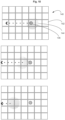
- Fig. 10 is a drawing depicting an exemplary washing operation with bead separation based on the use of instrument magnets.
- a liquid droplet 144 is dispensed onto the element array 140 of individual array elements 142.
- Magnetic beads are incorporated into the liquid droplet 144, which form a magnetic bead clump 146 under the magnetic field generated by one or more instrument magnets (not shown).
- a separation operation can be performed whereby the clumped magnetic beads 146 is split away from the liquid droplet 144.
- Fig. 10 shows that due to the magnet position relative to the liquid droplet 144, following the washing process a separation operation can be performed whereby the clumped magnetic beads 146 is split away from the liquid droplet 144.
- the droplet 144 containing the magnetic beads 146 is moved as indicated by the arrow in the figure by electrowetting forces across the element array 140.
- a region of high magnetic field is created by positioning an instrument magnet close the element array.
- the magnetic beads within the liquid droplet clump together as shown in the region of a high magnetic field gradient.
- a split occurs with the magnetic beads 146 (and a small surrounding shell of liquid) becoming separated from the liquid droplet 144.
- the separation operation does not work as intended as shown in Fig. 10 .
- the present invention enhances the implementation of droplet manipulation operations on the AM-EWOD element array of the microfluidic cartridge. This is achieved by ensuring the manipulation operations are performed at a position on the element array that is optimally aligned to a component of the microfluidic instrument.
- Embodiments of the enhanced system and method operate to measure the alignment of the microfluidic cartridge relative to the microfluidic instrument based on the position of a locator component of the microfluidic instrument, and adjust the software reaction protocol or script to control the position of the liquid droplet manipulation operations accordingly.
- An aspect of the invention is a microfluidic system and related method of operation that accounts for misalignment of an AM-EWOD cartridge relative to a microfluidic instrument by determining a position of a locator component of the microfluidic instrument, and modifying a reaction protocol or script of droplet manipulation operations in a manner that compensates for the misalignment.
- the microfluidic system includes: an electro-wetting on dielectric (EWOD) cartridge comprising an element array configured to receive liquid droplets, the element array comprising a plurality of individual array elements each including array element circuity comprising sensing circuitry that is integrated into the array element circuitry; a microfluidic instrument that is configured to receive the EWOD cartridge and having an electrically conductive locator that is external to the EWOD cartridge; and a control system configured perform electrowetting operations by controlling actuation voltages applied to the element array to perform manipulation operations as to liquid droplets present on the element array.
- EWOD electro-wetting on dielectric
- the control system further is configured to: read an output from the sensing circuitry, determine a position of the locator relative to the element array based on the output, and determine a misalignment of the EWOD cartridge relative to the microfluidic instrument based on the position of the locator.
- the microfluidic system further may include a voltage supply that applies a voltage perturbation to the locator, and the control system reads the output from the sensing circuitry in response to the voltage perturbation applied to the locator.
- the control system further is configured to adjust a droplet manipulation operation to compensate for the determined misalignment.
- the control system may perform such operations by executing program code stored on a non-transitory computer readable medium.
- Fig. 11 is a cross-sectional schematic drawing depicting a portion of an exemplary microfluidic system 150 in accordance with embodiments of the present invention.
- the microfluidic system 150 includes a microfluidic cartridge 152 having an element array 153 that is inserted into a microfluidic instrument 154 as previously described.
- instrument docking features 156 are shown with other instrument components being omitted from the figure for illustration purposes.
- the microfluidic instrument 154 includes a conductive locator 158 to which an electrical signal is applied by a voltage supply 160 via any suitable electrical connection 162.
- the conductive locator 158 is positioned, or can be moved within the microfluidic instrument so as to be positioned, within close proximity to or touching the lower surface of the microfluidic cartridge 152 corresponding to the TFT substrate.
- the locator 158 may be an existing feature in the microfluidic instrument 154, for example a magnet, optical component, heater, or the like. In a preferred implementation, accurate results are best achieved when the locator 158 is the same instrument component as to which precise alignment is desired to perform a droplet manipulation operation, e.g., an instrument magnet for a washing operation, a heater for a temperature-controlled reaction step, an optical component for an optical illumination or optical sensing operation, and so on. Accordingly, the locator 158 is a component of the microfluidic instrument 154 that is external from the microfluidic cartridge 152. In addition, different instrument components potentially may act as a locator, with the specific locator being selected by the control system from among the potential locators depending upon the operation to be performed at a given point or step in a reaction protocol or script.
- the microfluidic cartridge 152 is inserted into the microfluidic instrument 154 at an inserted position relative to the locator 158, as for example may be dictated by the instrument docking features 156.
- each array element in the element array 153 has integrated impedance or capacitance sensing circuity that is integrated into the array element circuitry.
- the sensing circuitry is used for sensing droplet position, and in accordance with embodiments of the present invention the sensing circuity also is configured to sense the position of the locator 158 when such locator is brought close to, or into contact with, the outer surface of one of the glass substrates of the AM-EWOD cartridge 152 as positioned within the microfluidic instrument 154.
- a voltage signal is applied to the locator 158 by the electrically connected voltage supply 160.
- a sensor image is read out by the instrument electronics and control system, which shows the transduced position of the locator 158 relative to the element array 153 of the microfluidic cartridge 152.
- a misalignment is determined by the control system analysis of the sensor image. Typically, two or more locator points may be detected to account for rotational as well as two-dimensional translational misalignment along the element array.
- the control system compensates for the misalignment by adjusting the reaction protocol or script. For example, the control system may control actuation voltages to nudge or slightly move the centroid of a liquid droplet relative to the element array so the centroid becomes optimally located relative to the conductive locator in the microfluidic instrument for performing the desired operation.
- Fig. 12 is a drawing depicting a two-dimensional array of elements including exemplary array element circuitry for an AM-EWOD device that embodies a previous design of Applicant.
- Fig. 12 depicts a 2 x 2 element array, although it will be appreciated that comparable principles are applicable to any array size.
- This basic array element circuitry has three thin film transistors (TFTs T1, T2, and T3) and two capacitors (C1 and C2), and is associated with seven addressing lines. The boundaries of a pixel are denoted by the dotted line. Row and column addressing lines are shown passing through the pixel in the horizontal and vertical directions respectively.
- Power supply connections which could in principle be supplied either in row or column lines, are shown by short horizontal lines (e.g. VCCA in Fig. 12 ). Connecting wires are shown with a solder dot, and without the dot, crossing lines do not connect.
- the R drop and C drop represent the resistance and capacitance across the device from the reference (top) electrode TP to the hydrophobic coating on which the liquid droplet may sit, and any other insulator layers incorporated into the device are represented by the capacitance CI.
- the values of R drop and C drop will vary based on the presence or absence of a liquid droplet, as described above with respect to Figs. 4A and 4B .
- Example AM-EWOD devices having this basic circuit design are described in Applicant's commonly assigned US 8,653,832 (Hadwen et al., issued February 18, 2014 ) and US 2018/0078934 (Hadwen et al., published March 22, 2018 ).
- the circuitry of Fig. 12 generally is operated as follows as to each array element.
- the voltage to be programmed is loaded onto addressing line SL, and a pulse is applied to the gate line GL appropriate for the row being programmed.
- This turns on a drive transistor T1
- the circuit node connected to the electrode is charged to the programmed voltage.
- GL is taken low, this voltage is preserved, stored on a storage capacitor C1.
- C1 is larger than the second or sensor capacitor C2 by at least about an order of magnitude.
- a reset transistor T2 is turned on by an RST signal, so the gate of a sensor readout transistor T3 charges to VCCA.
- VCCA is a reset potential chosen below the threshold voltage of T3 such that T3 remains off and any previous voltage is cleared.
- the RST signal is set low so that the gate of sensor readout transistor T3 is not driven and an addressing line RWS is pulsed.
- the electrode potential is perturbed to a higher voltage.
- the change in voltage achieved is principally a function of the ratio of capacitor C1 to the total capacitance at the electrode, which includes the load associated with whether the droplet is present or absent.
- the perturbation is coupled through the sensor capacitor C2 to the gate of T3, and transistor T3 is accordingly turned on to an extent determined by the amplitude of the pulse as coupled.
- Fig. 13 is a timing diagram for operation of the circuitry of Fig. 12 to sense a locator in accordance with embodiments of the present invention.
- a perturbation voltage is applied to an addressing line such as RWS.
- RWS addressing line
- the RWS line instead is maintained at a DC voltage and a perturbing voltage is applied directly to the locator (LOC), which is illustrated schematically in Fig. 11 by the electrical connection of the voltage supply 160 to the locator 158.
- LOC locator
- the resultant perturbation is coupled to the element electrodes of array elements in proximity to the locator.
- the magnitude of the perturbation of an element electrode potential varies in accordance with the degree of proximity to the locator.
- the magnitude of the perturbation of an element electrode potential in close proximity to the locator is greater as compared to the magnitude of the perturbation of an element electrode potential farther away from the locator.
- the magnitude of the electrode perturbation may be measured by measuring the resultant output current down the output column line COL.
- the magnitude of the output current measured from an element electrode in close proximity to the locator is greater as compared to the magnitude of the output current measured from an element electrode farther away from the locator.
- Fig. 14 is a drawing depicting an exemplary portion of an AM-EWOD cartridge 163 in relation to a locator 164 of a microfluidic instrument.
- the microfluid cartridge 163 includes a first hydrophobic coating 165 and a second hydrophobic coating 166 that define a channel 168 into which liquid droplets and a filler fluid (e.g., oil) may be dispensed.
- the cartridge 163 further may include a TFT glass substrate 170 onto which there is patterned an array of element electrodes 172.
- element electrodes 172a-d are shown in this example, although comparable principles apply to any size electrode array.
- the element electrodes 172a-d are spaced apart from the first hydrophobic coating 165 by an ion barrier 174, and a reference electrode 176 may be deposited on the second hydrophobic coating 166 opposite from the channel 168.
- Fig. 14 depicts a state in which a voltage is applied to the locator 164, which is conductive.
- the voltage perturbation applied to the locator 164 couples to the electrode array 172 capacitively through the glass substrate, as illustrated by representative field lines 178.
- the resultant electric field is strongest at the element electrode in closest proximity to the locator 164, which in this example is element electrode 172b.
- the electric field is weaker at element electrodes 172a and 172c, and essentially is negligible at element electrode 172d.
- the modified method of driving causes the element array to function as a capacitive array sensor that can detect the position and proximity of a conductive locator 164 that is external to the microfluidic cartridge 163.
- Fig. 15 is a drawing depicting an output image 180 that is derived from output currents measured from the element array 172 when a voltage perturbation is applied to the locator 164.
- the electrical interaction of the locator with the element array is indicated by the output image, with the shading in this example representing the degree of proximity of array elements to the locator with the darkest image portion 182 corresponding to the array element closest to the locator.
- Image portions that correspond to array elements farther form the locator are illustrated with less dark shading, with the shading darkness decreasing with distance from the locator. In this manner, the position of the locator relative to the element array is detectable to a resolution of around one array element (pixel).
- the output image 180 may be generated by the control system, and based on the output image 180, the control system can modify the reaction protocol or script to adjust droplet positioning as warranted for optimal positioning of the liquid droplet for a droplet manipulation operation.
- the locator sensing is considered active sensing in that the output image is derived from measuring the output current in response to a voltage perturbation applied to the locator.
- passive sensing of a conductive locator can be sufficient provided such circuitry is sufficiently sensitive to detect a passive conductive locator to which no electrical signal or perturbation is applied.
- An example of such a high-sensitive circuit is described in Applicant's Appl Serial No. 16/207,789 filed on December 3, 2018 .
- the sensing circuitry is improved by enhancing the sensitivity to very small capacitance variations, which for the present invention can be associated with locator positioning even without applying a voltage perturbation to the locator.
- a pre-charging effect is applied whereby the sensor readout transistor in an array element is altered to turn on the sensor readout transistor during a sensing phase.
- a positive pre-charging voltage may be applied across the gate and source of the sensor readout transistor to turn said transistor on, or a negative voltage may be applied across the gate and source of a p-type sensor readout transistor to turn on the sensor readout transistor.
- the element array may be operated in either a self or mutual capacitance mode as described in the '789 Application. The positioning of the locator in near proximity to the element array results in interaction with the electric field distribution in a similar way as shown in Fig. 14 , which results in a change in the capacitance measured as "present" at an electrode within the array.
- the present invention thus provides a way of measuring the microfluidic instrument/microfluidic cartridge alignment.
- the alignment information subsequently is utilized by the control system to perform a compensation operation that includes feedback of the measured position information to align droplet manipulation operations, and adjustment of the reaction protocol or script to optimally align the droplet manipulation operations relative to pertinent microfluidic instrument components that are external to the microfluidic cartridge, such as for example instrument magnets, heater, or optical components (which also may act as the locators in the compensation method).
- this may be accomplished by the control system controlling actuation voltages to nudge or slightly move the centroid of a liquid droplet relative to the element array so the droplet centroid becomes optimally located relative to the pertinent instrument component.
- An advantage of the present invention is that accounting for misalignment by adjusting the reaction protocol or script relaxes the mechanical tolerance requirements on cartridge/instrument alignment, which may make the cartridge and/or instrument easier and cheaper to produce.
- a further advantage is that the efficacy of a wash operation or other droplet manipulation operation may be improved by more accurate alignment by precise droplet position adjustments, which in the context of a wash operation in particular may reduce the volume of supernatant fluid surrounding a bead pellet, or otherwise may reduce the amounts of sample or reagent fluids that are required for a reaction protocol.
- the result is improved performance of droplet manipulation operations requiring critical or precise alignment, such as for example magnetic bead-based droplet operations (requiring precision alignment to instrument magnets), optical illumination and sensing (requiring precision alignment to optical components), and thermal control (requiring precision alignment to heater elements).
- Fig. 16 is a cross-sectional drawing depicting a variation on the embodiment of Fig. 11 , in which the exemplary portion on of the AM-EWOD cartridge 150 is positioned in relation to multiple locators, e.g., a first locator 158 and a second locator 159 of a microfluidic instrument 154.
- Fig. 17 is a drawing depicting a top view of the array of element electrodes 153 of Fig. 16 in relation to the locators 158 and 159.
- the locators 158 and 159 are positioned respectively at Positions A and B relative to the element array 153.
- the position of the cartridge 153 relative to the microfluidic instrument may be measured in two dimensions relative to the x-y plane of the element array. With such measurements, compensation of the reaction protocol or script for errors in position may be implemented accounting for planar x-y and rotational misalignment.
- Fig. 18 is a drawing depicting a variation on the embodiment of Figs. 11 and 16 , in which the exemplary portion on of the AM-EWOD cartridge 150 is positioned in relation to multiple locators e.g., a first locator 158 and a second locator 159 of a microfluidic instrument, and the locators may be positioned at different distances spaced apart from or relative to the element array 153.
- locators may correspond to instrument components utilized for certain operations, such as magnets for bead-based washing, heaters for thermal control, optical components for illumination and making optical measurements, and the like.
- magnets it is desirable to move the magnets to be adjacent to or nearly touching the cartridge substrate when bead-based washing is performed, and moved farther away from the cartridge substrate when washing is not being performed to preclude any undesirable effects from magnetic fields.
- location measurements with respect to multiple locators located at different distances with respect to the element array, and particularly instrument magnets may provide an enhanced measurement of cartridge position relative to the locators to aid in determining planar x-y or rotational misalignment.
- Fig. 19 is a drawing depicting an output image 184 that is derived from output currents measured from the element array 153 when a voltage perturbation is applied to the first and second locators 158 and 159.
- first locator 158 is essentially touching or near touching the cartridge substrate and second locator 159 is spaced farther apart from the cartridge substrate.
- the electrical interaction of the locators with the element array is illustrated with shading representing the degree of proximity of array elements to the locator, with the darker image portions corresponding to the array elements closest to the locator.
- image portion 186 is darkest as corresponding to the array element that is nearest to the first locator 158 that is essentially touching or near touching the cartridge substrate.
- Image portion 188 corresponds to an array element nearest to the second locator 159. Image portion 188 thus appears less darkly shaded as compared to image portion 186 because the second locator 159 is farther from the cartridge substrate than the first locator 158.
- Such measurements based on locators at different distances relative to the cartridge substrate may be used to detect the position of the cartridge in a "z" direction perpendicular to a plane of the electrode array 153.
- such measurements may be used to compensate functions performed by the instrument for which z-alignment is significant, such as for example intensity of a light source (e.g., when the cartridge is further away, light intensity is increased), positioning of pipettes for fluid input or extraction, or for focus adjustment of detection optics such as a camera.
- intensity of a light source e.g., when the cartridge is further away, light intensity is increased
- positioning of pipettes for fluid input or extraction e.g., when the cartridge is further away, light intensity is increased
- detection optics e.g., a camera
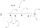
- Fig. 20 is a cross-sectional drawing depicting a variation on the embodiment of Fig. 18 , in which the exemplary portion on of the AM-EWOD cartridge 150 is positioned in relation to a magnet array 190 of a microfluidic instrument.
- the magnet array 190 includes multiple magnet elements 192 that may act as multiple locators. As seen in such figure, some of the magnet elements may be located essentially touching or near touching the cartridge substrate, while some of the magnet elements may be spaced apart from the substrate and maybe at different distances. As a matter of manufacturing, the magnet elements are movable toward and away from the cartridge substrate as needed for fluidic operations, and it desirable that all magnet elements be essentially touching the cartridge substrate when in the "up" position for use.
- the magnet elements 192 that form the magnet array 190 are to be moved up or down as a single component with a common drive mechanism. When brought into the "up" position adjacent to the cartridge substrate, however, not all magnet elements will be precisely touching the cartridge substrate due to the mechanical tolerances. Measurement of the intensity of coupling from each magnet position can be used to determine which magnets are touching, how far away non-touching magnets are, and whether this configuration is within a requisite specification. If not, an error can be reported. In this manner, using the magnet elements as locators for measuring cartridge positioning may be used as a quality control function to ensure that any mechanical misalignments or deviations of magnet elements or other instrument components fall within acceptable specification ranges.
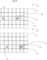
- FIG. 21 is a drawing depicting an exemplary compensation operation performed in accordance with embodiments of the present invention.
- an element array 200 of individual array elements 201 has dispensed thereon a liquid droplet 202 as to which a manipulation operation is to be performed as denoted by the arrow 204 (e.g., moving the position of the droplet).
- This operation is to be performed in relation to a locator 206 located within the microfluidic instrument, for example a magnet element.
- Fig. 21 illustrates the expected position of the locator 206 relative to the element array 200 based on mechanical insertion of the microfluidic cartridge relative to the microfluidic instrument. Based on simple mechanical assertion, the locator is expected to be adjacent to array element 208, and thus the initial reaction protocol or script calls for electrowetting forces to move the liquid droplet 202 to be positioned at the array element 208. As shown in the bottom potion of Fig. 21 , however, due to mechanical tolerances, the actual position of the locator 206 as measured using any of the embodiments above is adjacent to array element 210. In this example, therefore, there is a misalignment of one pixel down and one pixel right from the expected position (based on the orientation of the figure).
- the droplet 202 would not be placed optimally to perform the desired droplet manipulation operation, e.g., a bead-based washing using a magnet 206 followed by magnet separation such as shown in Fig. 10 when moving the droplet.
- the initial reaction protocol or script is modified to an adjusted reaction protocol or script, whereby the position of the liquid droplet 202 is modified from array element 208 to array element 210 to compensate for the misalignment.
- such compensation methods may be employed for any suitable reaction protocol in which certain droplet manipulation operations should be performed at fixed positions.
- Examples (without limitation) of such operations include fluid input and extraction, magnetic bead-based washing, thermal control, optical illumination and sensing, and the like.
- a single droplet operation is positionally adjusted.
- the position of the whole reaction protocol is adjusted.
- Comprehensive positional adjustment may be advantageous, for example, when fluid loading and/or extraction is automatically performed by the microfluidic instrument whereby it is advantageous to align the fluid ports with the loading/extracting instrument, and it would thus be beneficial that all the droplet operations in the reaction protocol be adjusted in accordance with fluid input and/or extraction positions.
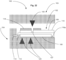
- Fig. 22 is a cross-sectional schematic drawing depicting a variation on the exemplary microfluidic system 100 of Fig. 8 , wherein the microfluidic instrument 104 includes an automated input/extraction component 103.
- the automated input/extraction component 103 may be an automated pipetting device integrated into the microfluidic instrument 104, or may be a component separate from the portion of the microfluidic instrument that receives the microfluidic cartridge.
- the position of an input/extraction element 105 such as for example a pipette, in the x-y plane above the plane of the element array of the microfluidic cartridge 102 may be adjusted in accordance with the measured position of the locators, which in this example are the magnets 124 although any suitable locators may be used.
- the position of the locators in turn is used to measure the position of the microfluidic cartridge 102.
- the microfluidic cartridge 102 includes a fluid port 107 that may be used for fluid input and/or extraction, and thus the position of the microfluidic cartridge is indicative of the position of the fluid port 107 relative to the pipette 105.
- the position of the automated input/extraction component 103 may be adjusted to optimally align the pipette 105 with the fluid port 107.
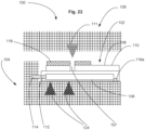
- Fig. 23 is a schematic drawing depicting a variation on the exemplary microfluidic system 100 of Fig. 22 , wherein the microfluidic instrument 104 includes an optical instrument 109.
- the optical instrument 109 implements optical illumination and/or sensing using an optics system 111, which may include for example an illumination light source (e.g., laser, LED) and/or an optical sensor (e.g. photodiode, avalanche photodiode), with the position of the optical instrument 109 being precisely determined relative to the element array.
- the optical instrument 109 may be integrated as part of the microfluidic instrument or a component separate from the portion of the microfluidic instrument that receives the microfluidic cartridge.
- the position of the optical instrument 109 relative to the element array of the microfluidic cartridge 102 may be adjusted in accordance with the measured position of the locators, which in this example again are the magnets 124 although any suitable locators may be used. If there is a misalignment of the microfluidic cartridge relative to the optical instrument 109 based on the measurements of the locator positions, the position of the optical instrument 109 may be adjusted to optimally align the optics system 111 with any array element that has a liquid droplet that is to be optically illuminated and/or sensed.
- An aspect of the invention is a microfluidic system and related method of operation that accounts for misalignment of an AM-EWOD cartridge relative to a microfluidic instrument (i.e. an instrument that controls the microfluidic cartridge) by determining a position of a locator component of the microfluidic instrument, and modifying a reaction protocol or script of droplet manipulation operations in a manner that compensates for the misalignment.
- a microfluidic instrument i.e. an instrument that controls the microfluidic cartridge
- the microfluidic system includes: an electro-wetting on dielectric (EWOD) cartridge comprising an element array configured to receive liquid droplets, the element array comprising a plurality of individual array elements each including array element circuity comprising sensing circuitry that is integrated into the array element circuitry; a microfluidic instrument that is configured to receive the EWOD cartridge and having an electrically conductive locator that is external to the EWOD cartridge; and a control system configured to perform electrowetting operations by controlling actuation voltages applied to the element array to perform manipulation operations as to liquid droplets present on the element array.
- EWOD electro-wetting on dielectric
- the control system further is configured to: read an output from the sensing circuitry; determine a position of the locator relative to the element array based on the output; and determine a misalignment of the EWOD cartridge relative to the microfluidic instrument based on the determined position of the locator.
- the microfluidic system may include one or more of the following features, either individually or in combination.
- the system further includes a voltage supply that applies a voltage perturbation to the locator, and the control system reads the output from the sensing circuitry in response to the voltage perturbation applied to the locator.
- the locator includes a magnet element.
- the locator comprises a magnet array comprising a plurality of magnet elements that are movable relative to the EWOD cartridge, and the controller is configured to determine the position of each magnet element relative to the element array.
- the locator comprises a plurality of locator elements and the controller is configured to determine the position of each locator element relative to the element array.
- the locator includes one or more of a magnet element, a heater, and an optical component.
- the controller further is configured to adjust a manipulation operation of a liquid droplet to compensate for the determined misalignment of the EWOD cartridge relative to the microfluidic instrument.
- the controller is configured to adjust the manipulation operation by performing an electrowetting operation to move a liquid droplet to a position that is optimal relative to a component of the microfluidic instrument that is employed during the manipulation operation.
- the component of the microfluidic instrument that is employed during the manipulation operation includes the locator.
- the method of operating includes the steps of: reading an output from the sensing circuitry; determining a position of the locator relative to the element array based on the output; determining a misalignment of the EWOD cartridge relative to the microfluidic instrument based on the position of the locator; and adjusting a manipulation operation of a liquid droplet to compensate for the determined misalignment of the EWOD cartridge relative to the microfluidic instrument.
- the method of operating may include one or more of the following features, either individually or in combination.
- the method further includes applying a voltage perturbation to the locator, and reading the output from the sensing circuitry in response to the voltage perturbation applied to the locator.
- the method further includes determining a misalignment of the EWOD cartridge relative to a component of the microfluidic instrument that is employed during the manipulation operation; and adjusting the manipulation operation by performing an electrowetting operation to move a liquid droplet to a position that is optimal relative to the component of the microfluidic instrument that is employed during the manipulation operation.
- the component of the microfluidic instrument that is employed during the manipulation operation includes the locator.
- the locator is a magnet element and the manipulation operation is a magnetic bead-based washing and separation operation.
- a reaction protocol comprises a plurality of manipulation operations
- the method further comprises performing an electrowetting operation to move one or more liquid droplets to respective positions that are optimal relative to components of the microfluidic instrument that are employed during a plurality of manipulation operations that are part of the reaction protocol.
- the locator includes multiple locator elements, and the method further comprises determining a misalignment of the EWOD cartridge relative to the microfluidic instrument in the two-dimensional x-y plane corresponding to the element array, and/or determining a rotational misalignment of the EWOD cartridge relative to the microfluidic instrument.
- the locator comprises a magnet array having plurality of magnet elements that is movable between a first position closest to the EWOD cartridge and a second position farthest from the EWOD cartridge, the method comprising the steps of: moving the magnet array to the first position; determining a distance of each magnet element from the EWOD cartridge; determining whether the distances satisfy a specification; and outputting the result of the determination of whether the distances satisfy the specification.
- the method further includes generating an output image based on the output from the sensing circuitry that indicates the position of the locator relative to the element array.
- Another aspect of the invention is a non-transitory computer-readable medium storing program code which is executed by a processing device for controlling a microfluidic system, the processing device being configured to perform electrowetting operations by controlling actuation voltages applied to the element array to perform manipulation operations as to liquid droplets present on the element array.
- the program code is executable by the processing device to perform the method steps accordingly to any of the embodiments.
- the described embodiments could be used to provide an enhanced AM-EWOD device.
- the AM-EWOD device could form a part of a lab-on-a-chip system.
- Such devices could be used for optical detection of biochemical or physiological materials, such as for cell detection and cell counting.
- Applications include healthcare diagnostic testing, material testing, chemical or biochemical material synthesis, proteomics, tools for research in life sciences and forensic science.
Landscapes
- Chemical & Material Sciences (AREA)
- Dispersion Chemistry (AREA)
- Health & Medical Sciences (AREA)
- Physics & Mathematics (AREA)
- Analytical Chemistry (AREA)
- General Health & Medical Sciences (AREA)
- Hematology (AREA)
- Clinical Laboratory Science (AREA)
- Chemical Kinetics & Catalysis (AREA)
- General Physics & Mathematics (AREA)
- Optics & Photonics (AREA)
- Physical Or Chemical Processes And Apparatus (AREA)
Claims (15)
- Mikrofluidsystem, umfassend:eine Elektrobenetzungskartusche auf Dielektrikum (EWOD) (105,152,163), die eine Elementanordnung (140, 153, 200) umfasst, die so konfiguriert ist, dass sie Flüssigkeitströpfchen aufnimmt, wobei die Elementanordnung eine Vielzahl einzelner Anordnungslemente (142, 201, 208, 210) umfasst, die jeweils eine Anordnungslementschaltung umfassen, die eine Sensorschaltung (90) umfasst, die in die Anordnungslementschaltung integriert ist;ein mikrofluidisches Instrument (104, 154), das so konfiguriert ist, dass es die EWOD-Kartusche (105, 152, 163) aufnimmt und einen elektrisch leitfähigen Ortungsempfänger (158, 159, 164, 206, LOC) aufweist, der sich außerhalb der EWOD-Kartusche befindet; undein Steuersystem (126), das so konfiguriert ist, dass es Elektrobenetzungsvorgänge durch Steuern der an die Elementanordnung (140, 153, 200) angelegten Betätigungsspannungen durchführt, um Manipulationsvorgänge an auf der Elementanordnung vorhandenen Flüssigkeitströpfchen (144,202) durchzuführen;wobei das Steuersystem (126) ferner dazu konfiguriert ist:eine Ausgabe von der Sensorschaltung (90) liest;eine Position des Ortungsempfängers (158, 159, 164, 206) relativ zu der Elementanordnung (140, 153, 172, 200) basierend auf der Ausgabe bestimmt;eine Fehlausrichtung der EWOD-Kartusche (105, 152, 163) relativ zu dem mikrofluidischen Instrument (104, 154) basierend auf der bestimmten Position des Ortungsempfängers (158, 159, 164, 206) bestimmt; undeinen Manipulationsvorgang eines Flüssigkeitströpfchens (144,202) anpasst, um die bestimmte Fehlausrichtung der EWOD-Kartusche (105, 152, 163) relativ zu dem mikrofluidischen Instrument (104, 154) auszugleichen.
- Mikrofluidsystem nach Anspruch 1, ferner umfassend eine Spannungsversorgung (160), die dazu ausgebildet ist, eine Spannungsstörung auf den Ortungsempfänger (158, 159, 164, 206, LOC) anzuwenden, und wobei das Steuersystem (126) dazu ausgebildet ist, die Ausgabe von der Sensorschaltung als Reaktion auf die auf den Ortungsempfänger angewendete Spannungsstörung zu lesen.
- Mikrofluidsystem nach einem der Ansprüche 1 bis 2, wobei der Ortungsempfänger ein Magnetelement (124) umfasst;und/oder wobei der Ortungsempfänger eine Magnetanordnung (190) umfasst, das eine Vielzahl von Magnetelementen (192) umfasst, die relativ zur EWOD-Kartusche beweglich sind, und wobei die Steuerung so konfiguriert ist, dass er die Position jedes Magnetelements relativ zur Elementanordnung bestimmt;und/oder wobei der Ortungsempfänger eine Vielzahl von Lokalisierungselementen umfasst und die Steuerung so konfiguriert ist, dass er die Position jedes Lokalisierungselements relativ zur Elementanordnung bestimmt;und/oder wobei der Ortungsempfänger ein oder mehrere eines Magnetelement (124), einer Heizung (120) und einer optischen Komponente (122) umfasst.
- Mikrofluidsystem nach Anspruch 1, 2 oder 3, wobei das Steuersystem (126) dazu konfiguriert ist, den Manipulationsvorgang durch Ausführen eines Elektrobenetzungsvorgangs anzupassen, um einen Flüssigkeitströpfchen (202) an eine Position zu bewegen, die im Verhältnis zu einer Komponente des Mikrofluidinstruments, das während des Manipulationsvorgangs verwendet wird, optimal ist.
- Mikrofluidsystem nach Anspruch 4, wobei die Komponente des Mikrofluidinstruments, die während des Manipulationsvorgangs verwendet wird, den Ortungsempfänger umfasst.
- Betriebsverfahren zum Betreiben eines Mikrofluidsystems;
wobei das Mikrofluidsystem Folgendes umfasst:eine Elektrobenetzungskartusche auf Dielektrikum (EWOD) (105, 152, 163), die eine Elementanordnung (140, 153, 200) umfasst, die so konfiguriert ist, dass sie Flüssigkeitströpfchen (144,202) aufnimmt, wobei die Elementanordnung eine Vielzahl einzelner Anordnungslemente (142, 201, 208, 210) umfasst, die jeweils eine Anordnungslementschaltung umfassen, die Sensorschaltung (90) umfasst, die in die Anordnungslementschaltung integriert ist;ein mikrofluidisches Instrument (104, 154), das so konfiguriert ist, dass es die EWOD-Kartusche (105, 152, 163) aufnimmt und einen elektrisch leitfähigen Ortungsempfänger (158, 159, 164, 206, LOC) aufweist, der sich außerhalb der EWOD-Kartusche befindet; undein Steuersystem (126), das so konfiguriert ist, dass es Elektrobenetzungsvorgänge durch Steuern der an die Elementanordnung (140, 153, 200) angelegten Betätigungsspannungen durchführt, um Manipulationsvorgänge an auf der Elementanordnung vorhandenen Flüssigkeitströpfchen (144,202) durchzuführen;wobei Betriebsverfahren die folgende Schritte umfasst:Lesen einer Ausgabe von der Sensorschaltung (90);Bestimmen einer Position des Ortungsempfängers (158, 159, 164, 206, LOC) relativ zu der Elementanordnung (140, 153, 200) basierend auf der Ausgabe;Bestimmen einer Fehlausrichtung der EWOD-Kartusche (105, 152, 163) relativ zu dem mikrofluidischen Instrument (104, 154) basierend auf der Position des Ortungsempfängers; undAnpassen eines Manipulationsvorgangs eines Flüssigkeitströpfchens (144,202), um die bestimmte Fehlausrichtung der EWOD-Kartusche (105, 152, 163) relativ zu dem mikrofluidischen Instrument (104, 154) auszugleichen. - Betriebsverfahren nach Anspruch 6, ferner umfassend das Anlegen einer Spannungsstörung an den Ortungsempfänger (158, 159, 164, 206, LOC) und das Lesen der Ausgabe von der Sensorschaltung (90) als Reaktion auf die an den Ortungsempfänger angelegte Spannungsstörung.
- Betriebsverfahren nach einem der Ansprüche 6 bis 7, das weiterhin Folgendes umfasst:Bestimmen einer Fehlausrichtung der EWOD-Kartusche (105, 152, 163) relativ zu einer Komponente des mikrofluidischen Instruments, das während des Manipulationsvorgangs verwendet wird; undAnpassen des Manipulationsvorgangs durch Ausführen eines Elektrobenetzungsvorgangs, um einen Flüssigkeitströpfchen (202) in eine Position zu bewegen, die relativ zu der Komponente des mikrofluidischen Instruments, das während des Manipulationsvorgangs verwendet wird, optimal ist.
- Betriebsverfahren nach Anspruch 8, wobei die Komponente des mikrofluidischen Instruments, die während des Manipulationsvorgangs verwendet wird, den Ortungsempfänger (158, 159, 164, 206, LOC) umfasst.
- Betriebsverfahren nach einem der Ansprüche 6 bis 9, wobei der Ortungsempfänger (158, 159, 164, 206, LOC) ein Magnetelement (124) ist und der Manipulationsvorgang ein auf magnetischen Perlen basierender Wasch- und Trennvorgang ist.
- Betriebsverfahren nach einem der Ansprüche 6 bis 10, wobei ein Reaktionsprotokoll eine Vielzahl von Manipulationsvorgängen umfasst und das Verfahren weiterhin das Durchführen eines Elektrobenetzungsvorgangs umfasst, um ein oder mehrere Flüssigkeitströpfchen (144,202) an jeweilige Positionen zu bewegen, die im Verhältnis zu den Komponenten des Mikrofluidinstruments (104, 154), die während einer Vielzahl von Manipulationsvorgängen verwendet werden, die Teil des Reaktionsprotokolls sind, optimal sind.
- Betriebsverfahren nach einem der Ansprüche 6 bis 11, wobei der Ortungsempfänger mehrere Lokalisierungselemente (158, 159) umfasst und das Verfahren ferner das Bestimmen einer Fehlausrichtung der EWOD-Kartusche (105, 152, 163) relativ zu dem mikrofluidischen Instrument in der zweidimensionalen x-y-Ebene, die der Elementanordnung entspricht, und/oder das Bestimmen einer Rotationsfehlausrichtung der EWOD-Kartusche (105, 152, 163) relativ zu dem mikrofluidischen Instrument umfasst.
- Betriebsverfahren nach einem der Ansprüche 6 bis 12, wobei der Ortungsempfänger eine Magnetanordnung (190) mit einer Vielzahl von Magnetelementen (192) umfasst, die zwischen einer ersten Position, die der EWOD-Kartusche (105, 152, 163) am nächsten ist, und einer zweiten Position, die am weitesten von der EWOD-Kartusche (105, 152, 163) entfernt ist, beweglich ist, wobei das Verfahren die folgenden Schritte umfasst:Bewegen der Magnetanordnung (190) in die erste Position;Bestimmen eines Abstands jedes Magnetelements (192) von der EWOD-Kartusche (105, 152, 163);Bestimmen, ob die Abstände eine Spezifikation erfüllen; undAusgeben des Ergebnisses der Bestimmung, ob die Abstände die Spezifikation erfüllen.
- Betriebsverfahren nach einem der Ansprüche 6 bis 13, ferner umfassend das Erzeugen eines Ausgabebildes auf der Grundlage der Ausgabe der Sensorschaltung, das die Position des Ortungsempfängers (158, 159, 164, 206, LOC) relativ zur Elementanordnung (140, 153, 172, 200) angibt.
- Nicht-flüchtiges computerlesbares Medium, das Programmcode speichert, der von einer Verarbeitungsvorrichtung zur Steuerung eines Mikrofluidsystems ausgeführt wird;wobei das Mikrofluidsystem eine Elektrobenetzungskartusche (EWOD) (105, 152, 163) umfasst, die eine Elementanordnung (140, 153, 172, 200) umfasst, die so konfiguriert ist, dass sie Flüssigkeitströpfchen (144,202) aufnimmt, wobei die Elementanordnung eine Vielzahl einzelner Anordnungslemente (142, 201, 208, 210) umfasst, die jeweils eine Anordnungslementschaltung umfassen, die eine Sensorschaltung (90) umfasst, die in die Anordnungslementschaltung integriert ist; und ein Mikrofluidinstrument (104, 154), das so konfiguriert ist, dass es die EWOD-Kartusche (105, 152, 163) aufnimmt und einen elektrisch leitfähigen Ortungsempfänger aufweist, der sich außerhalb der EWOD-Kartusche (105, 152, 163) befindet;wobei die Verarbeitungsvorrichtung so konfiguriert ist, dass sie Elektrobenetzungsvorgänge durch Steuern der an die Elementanordnung (140, 153, 172, 200) angelegten Betätigungsspannungen durchführt, um Manipulationsvorgänge an Flüssigkeitströpfchen (144,202) durchzuführen, die auf der Elementanordnung (140, 153, 172, 200) vorhanden sind;wobei der Programmcode durch die Verarbeitungsvorrichtung ausführbar ist, um die Schritte eines Verfahrens nach einem der Ansprüche 6 bis 14 durchzuführen.
Applications Claiming Priority (2)
| Application Number | Priority Date | Filing Date | Title |
|---|---|---|---|
| US16/298,063 US10870114B2 (en) | 2019-03-11 | 2019-03-11 | EWOD cartridge position sensing when docked in EWOD instrument |
| PCT/IB2020/051914 WO2020183303A1 (en) | 2019-03-11 | 2020-03-05 | Ewod cartridge position sensing when docked in ewod instrument |
Publications (2)
| Publication Number | Publication Date |
|---|---|
| EP3906115A1 EP3906115A1 (de) | 2021-11-10 |
| EP3906115B1 true EP3906115B1 (de) | 2024-12-25 |
Family
ID=69846152
Family Applications (1)
| Application Number | Title | Priority Date | Filing Date |
|---|---|---|---|
| EP20712407.4A Active EP3906115B1 (de) | 2019-03-11 | 2020-03-05 | Ewod-kartuschenpositionserfassung beim andocken in ein ewod-instrument |
Country Status (4)
| Country | Link |
|---|---|
| US (1) | US10870114B2 (de) |
| EP (1) | EP3906115B1 (de) |
| CN (1) | CN113573813B (de) |
| WO (1) | WO2020183303A1 (de) |
Families Citing this family (3)
| Publication number | Priority date | Publication date | Assignee | Title |
|---|---|---|---|---|
| EP3812042A1 (de) * | 2019-10-25 | 2021-04-28 | Sharp Life Science (EU) Limited | Ewod-vorrichtung mit erfassungsvorrichtung |
| CN115646565B (zh) * | 2022-11-11 | 2023-03-21 | 杭州毫厘科技有限公司 | 微流体检测装置、流体质量监测设备及部件更换方法 |
| GB202307494D0 (en) | 2023-05-18 | 2023-07-05 | Oxford Nanopore Tech Ltd | Nanopore sequencing and preparation modular instrument |
Citations (1)
| Publication number | Priority date | Publication date | Assignee | Title |
|---|---|---|---|---|
| WO2020249804A2 (en) * | 2019-06-14 | 2020-12-17 | Sharp Life Science (Eu) Limited | Magnetic particle extraction in an ewod instrument |
Family Cites Families (16)
| Publication number | Priority date | Publication date | Assignee | Title |
|---|---|---|---|---|
| US7163612B2 (en) | 2001-11-26 | 2007-01-16 | Keck Graduate Institute | Method, apparatus and article for microfluidic control via electrowetting, for chemical, biochemical and biological assays and the like |
| US7939021B2 (en) * | 2007-05-09 | 2011-05-10 | Advanced Liquid Logic, Inc. | Droplet actuator analyzer with cartridge |
| US8685325B2 (en) * | 2010-03-09 | 2014-04-01 | Sparkle Power Inc. | Field-programmable lab-on-a-chip based on microelectrode array architecture |
| US8653832B2 (en) | 2010-07-06 | 2014-02-18 | Sharp Kabushiki Kaisha | Array element circuit and active matrix device |
| US8173000B1 (en) | 2011-01-18 | 2012-05-08 | Sharp Kabushiki Kaisha | Active matrix device and method of driving the same |
| CN102671722B (zh) * | 2011-02-17 | 2015-03-11 | 王崇智 | 基于微电极阵列结构的现场可编程芯片实验室 |
| KR102045809B1 (ko) | 2012-12-13 | 2019-11-18 | 엘지디스플레이 주식회사 | 터치센서 일체형 표시장치 |
| US9492824B2 (en) | 2013-01-16 | 2016-11-15 | Sharp Kabushiki Kaisha | Efficient dilution method, including washing method for immunoassay |
| US10005080B2 (en) * | 2014-11-11 | 2018-06-26 | Genmark Diagnostics, Inc. | Instrument and cartridge for performing assays in a closed sample preparation and reaction system employing electrowetting fluid manipulation |
| US20160178559A1 (en) * | 2014-12-17 | 2016-06-23 | Lifescan Scotland Limited | Universal strip port connector |
| GB2533951A (en) | 2015-01-08 | 2016-07-13 | Sharp Kk | Active matrix device and method of driving |
| EP3313760B1 (de) | 2015-06-23 | 2021-12-15 | Siti - B&T Group S.p.A. | Aufbewahrungsvorrichtung für keramikprodukte und dergleichen |
| US20170056887A1 (en) * | 2015-08-28 | 2017-03-02 | Sharp Kabushiki Kaisha | Droplet microfluidic device and methods of sensing the results of an assay therein |
| US10078986B2 (en) | 2015-09-15 | 2018-09-18 | Sharp Life Science (Eu) Limited | Active matrix device and method of driving |
| US20170138901A1 (en) * | 2015-11-17 | 2017-05-18 | IIIumina, Inc. | Electrode drive and sensing circuits and methods |
| CN107497509B (zh) * | 2017-10-11 | 2020-05-26 | 京东方科技集团股份有限公司 | 微流控系统及其驱动方法 |
-
2019
- 2019-03-11 US US16/298,063 patent/US10870114B2/en active Active
-
2020
- 2020-03-05 EP EP20712407.4A patent/EP3906115B1/de active Active
- 2020-03-05 CN CN202080020525.5A patent/CN113573813B/zh active Active
- 2020-03-05 WO PCT/IB2020/051914 patent/WO2020183303A1/en not_active Ceased
Patent Citations (1)
| Publication number | Priority date | Publication date | Assignee | Title |
|---|---|---|---|---|
| WO2020249804A2 (en) * | 2019-06-14 | 2020-12-17 | Sharp Life Science (Eu) Limited | Magnetic particle extraction in an ewod instrument |
Also Published As
| Publication number | Publication date |
|---|---|
| WO2020183303A1 (en) | 2020-09-17 |
| US10870114B2 (en) | 2020-12-22 |
| US20200290050A1 (en) | 2020-09-17 |
| CN113573813B (zh) | 2023-06-16 |
| CN113573813A (zh) | 2021-10-29 |
| EP3906115A1 (de) | 2021-11-10 |
Similar Documents
| Publication | Publication Date | Title |
|---|---|---|
| EP3381557B1 (de) | Am-ewod-vorrichtung und steuerungsverfahren mit intermittierenden betätigungsmustern | |
| EP3350584B1 (de) | Aktivmatrixvorrichtung und verfahren zur ansteuerung | |
| US10870114B2 (en) | EWOD cartridge position sensing when docked in EWOD instrument | |
| CN111250178B (zh) | 具有感测列检测电路的am-ewod电路配置 | |
| US20030021725A1 (en) | Indicator components for microfluidic systems | |
| EP3417940B1 (de) | Ewod-vorrichtung mit rückhaltefunktion für flüssigkeitsbeladung | |
| EP3613506B1 (de) | Mikrofluidische vorrichtung und verfahren für digitale assays in biologischen analysen | |
| US11577244B2 (en) | Microfluidic device and a method of loading fluid therein | |
| US12502673B2 (en) | Magnetic particle extraction in an EWOD instrument | |
| US11224877B2 (en) | Systems and methods for analyzing droplets | |
| US10682874B2 (en) | Droplet dispensing apparatus | |
| EP3662999B1 (de) | Am-ewod-array-elementschaltung mit hoher empfindlichkeit für kleine kapazität | |
| EP3623049A1 (de) | Mikrofluidische vorrichtung und verfahren zum laden von fluid darin | |
| EP3663000B1 (de) | Am-ewod-array-elementschaltung mit integrierter erfassung und verfahren zur erfassung der tröpfchenverbindung | |
| EP3586967B1 (de) | Adaptive verfahren zur tröpfchenströmung in einem vorrichtung mit aktiv-matrix-elektrobenetzung | |
| US11364497B2 (en) | Embedded microfluidic devices | |
| US20260009762A1 (en) | Flexible capillary array device and related systems and methods |
Legal Events
| Date | Code | Title | Description |
|---|---|---|---|
| STAA | Information on the status of an ep patent application or granted ep patent |
Free format text: STATUS: UNKNOWN |
|
| STAA | Information on the status of an ep patent application or granted ep patent |
Free format text: STATUS: THE INTERNATIONAL PUBLICATION HAS BEEN MADE |
|
| PUAI | Public reference made under article 153(3) epc to a published international application that has entered the european phase |
Free format text: ORIGINAL CODE: 0009012 |
|
| STAA | Information on the status of an ep patent application or granted ep patent |
Free format text: STATUS: REQUEST FOR EXAMINATION WAS MADE |
|
| 17P | Request for examination filed |
Effective date: 20210806 |
|
| AK | Designated contracting states |
Kind code of ref document: A1 Designated state(s): AL AT BE BG CH CY CZ DE DK EE ES FI FR GB GR HR HU IE IS IT LI LT LU LV MC MK MT NL NO PL PT RO RS SE SI SK SM TR |
|
| DAV | Request for validation of the european patent (deleted) | ||
| DAX | Request for extension of the european patent (deleted) | ||
| P01 | Opt-out of the competence of the unified patent court (upc) registered |
Effective date: 20230525 |
|
| GRAP | Despatch of communication of intention to grant a patent |
Free format text: ORIGINAL CODE: EPIDOSNIGR1 |
|
| STAA | Information on the status of an ep patent application or granted ep patent |
Free format text: STATUS: GRANT OF PATENT IS INTENDED |
|
| INTG | Intention to grant announced |
Effective date: 20240910 |
|
| GRAS | Grant fee paid |
Free format text: ORIGINAL CODE: EPIDOSNIGR3 |
|
| GRAA | (expected) grant |
Free format text: ORIGINAL CODE: 0009210 |
|
| STAA | Information on the status of an ep patent application or granted ep patent |
Free format text: STATUS: THE PATENT HAS BEEN GRANTED |
|
| AK | Designated contracting states |
Kind code of ref document: B1 Designated state(s): AL AT BE BG CH CY CZ DE DK EE ES FI FR GB GR HR HU IE IS IT LI LT LU LV MC MK MT NL NO PL PT RO RS SE SI SK SM TR |
|
| REG | Reference to a national code |
Ref country code: GB Ref legal event code: FG4D |
|
| REG | Reference to a national code |
Ref country code: CH Ref legal event code: EP |
|
| REG | Reference to a national code |
Ref country code: DE Ref legal event code: R096 Ref document number: 602020043634 Country of ref document: DE |
|
| REG | Reference to a national code |
Ref country code: IE Ref legal event code: FG4D |
|
| REG | Reference to a national code |
Ref country code: NL Ref legal event code: FP |
|
| REG | Reference to a national code |
Ref country code: LT Ref legal event code: MG9D |
|
| PG25 | Lapsed in a contracting state [announced via postgrant information from national office to epo] |
Ref country code: HR Free format text: LAPSE BECAUSE OF FAILURE TO SUBMIT A TRANSLATION OF THE DESCRIPTION OR TO PAY THE FEE WITHIN THE PRESCRIBED TIME-LIMIT Effective date: 20241225 |
|
| PGFP | Annual fee paid to national office [announced via postgrant information from national office to epo] |
Ref country code: DE Payment date: 20250327 Year of fee payment: 6 |
|
| PG25 | Lapsed in a contracting state [announced via postgrant information from national office to epo] |
Ref country code: FI Free format text: LAPSE BECAUSE OF FAILURE TO SUBMIT A TRANSLATION OF THE DESCRIPTION OR TO PAY THE FEE WITHIN THE PRESCRIBED TIME-LIMIT Effective date: 20241225 |
|
| PGFP | Annual fee paid to national office [announced via postgrant information from national office to epo] |
Ref country code: NL Payment date: 20250327 Year of fee payment: 6 |
|
| PG25 | Lapsed in a contracting state [announced via postgrant information from national office to epo] |
Ref country code: BG Free format text: LAPSE BECAUSE OF FAILURE TO SUBMIT A TRANSLATION OF THE DESCRIPTION OR TO PAY THE FEE WITHIN THE PRESCRIBED TIME-LIMIT Effective date: 20241225 |
|
| PG25 | Lapsed in a contracting state [announced via postgrant information from national office to epo] |
Ref country code: NO Free format text: LAPSE BECAUSE OF FAILURE TO SUBMIT A TRANSLATION OF THE DESCRIPTION OR TO PAY THE FEE WITHIN THE PRESCRIBED TIME-LIMIT Effective date: 20250325 |
|
| PG25 | Lapsed in a contracting state [announced via postgrant information from national office to epo] |
Ref country code: LV Free format text: LAPSE BECAUSE OF FAILURE TO SUBMIT A TRANSLATION OF THE DESCRIPTION OR TO PAY THE FEE WITHIN THE PRESCRIBED TIME-LIMIT Effective date: 20241225 Ref country code: GR Free format text: LAPSE BECAUSE OF FAILURE TO SUBMIT A TRANSLATION OF THE DESCRIPTION OR TO PAY THE FEE WITHIN THE PRESCRIBED TIME-LIMIT Effective date: 20250326 |
|
| PGFP | Annual fee paid to national office [announced via postgrant information from national office to epo] |
Ref country code: FR Payment date: 20250325 Year of fee payment: 6 |
|
| PGFP | Annual fee paid to national office [announced via postgrant information from national office to epo] |
Ref country code: GB Payment date: 20250327 Year of fee payment: 6 |
|
| PG25 | Lapsed in a contracting state [announced via postgrant information from national office to epo] |
Ref country code: RS Free format text: LAPSE BECAUSE OF FAILURE TO SUBMIT A TRANSLATION OF THE DESCRIPTION OR TO PAY THE FEE WITHIN THE PRESCRIBED TIME-LIMIT Effective date: 20250325 |
|
| REG | Reference to a national code |
Ref country code: AT Ref legal event code: MK05 Ref document number: 1753729 Country of ref document: AT Kind code of ref document: T Effective date: 20241225 |
|
| PG25 | Lapsed in a contracting state [announced via postgrant information from national office to epo] |
Ref country code: SM Free format text: LAPSE BECAUSE OF FAILURE TO SUBMIT A TRANSLATION OF THE DESCRIPTION OR TO PAY THE FEE WITHIN THE PRESCRIBED TIME-LIMIT Effective date: 20241225 |
|
| PG25 | Lapsed in a contracting state [announced via postgrant information from national office to epo] |
Ref country code: PL Free format text: LAPSE BECAUSE OF FAILURE TO SUBMIT A TRANSLATION OF THE DESCRIPTION OR TO PAY THE FEE WITHIN THE PRESCRIBED TIME-LIMIT Effective date: 20241225 |
|
| PG25 | Lapsed in a contracting state [announced via postgrant information from national office to epo] |
Ref country code: ES Free format text: LAPSE BECAUSE OF FAILURE TO SUBMIT A TRANSLATION OF THE DESCRIPTION OR TO PAY THE FEE WITHIN THE PRESCRIBED TIME-LIMIT Effective date: 20241225 |
|
| PG25 | Lapsed in a contracting state [announced via postgrant information from national office to epo] |
Ref country code: IS Free format text: LAPSE BECAUSE OF FAILURE TO SUBMIT A TRANSLATION OF THE DESCRIPTION OR TO PAY THE FEE WITHIN THE PRESCRIBED TIME-LIMIT Effective date: 20250425 |
|
| PG25 | Lapsed in a contracting state [announced via postgrant information from national office to epo] |
Ref country code: PT Free format text: LAPSE BECAUSE OF FAILURE TO SUBMIT A TRANSLATION OF THE DESCRIPTION OR TO PAY THE FEE WITHIN THE PRESCRIBED TIME-LIMIT Effective date: 20250428 |
|
| PG25 | Lapsed in a contracting state [announced via postgrant information from national office to epo] |
Ref country code: EE Free format text: LAPSE BECAUSE OF FAILURE TO SUBMIT A TRANSLATION OF THE DESCRIPTION OR TO PAY THE FEE WITHIN THE PRESCRIBED TIME-LIMIT Effective date: 20241225 |
|
| PG25 | Lapsed in a contracting state [announced via postgrant information from national office to epo] |
Ref country code: AT Free format text: LAPSE BECAUSE OF FAILURE TO SUBMIT A TRANSLATION OF THE DESCRIPTION OR TO PAY THE FEE WITHIN THE PRESCRIBED TIME-LIMIT Effective date: 20241225 Ref country code: RO Free format text: LAPSE BECAUSE OF FAILURE TO SUBMIT A TRANSLATION OF THE DESCRIPTION OR TO PAY THE FEE WITHIN THE PRESCRIBED TIME-LIMIT Effective date: 20241225 |
|
| PG25 | Lapsed in a contracting state [announced via postgrant information from national office to epo] |
Ref country code: SK Free format text: LAPSE BECAUSE OF FAILURE TO SUBMIT A TRANSLATION OF THE DESCRIPTION OR TO PAY THE FEE WITHIN THE PRESCRIBED TIME-LIMIT Effective date: 20241225 |
|
| PG25 | Lapsed in a contracting state [announced via postgrant information from national office to epo] |
Ref country code: CZ Free format text: LAPSE BECAUSE OF FAILURE TO SUBMIT A TRANSLATION OF THE DESCRIPTION OR TO PAY THE FEE WITHIN THE PRESCRIBED TIME-LIMIT Effective date: 20241225 |
|
| PG25 | Lapsed in a contracting state [announced via postgrant information from national office to epo] |
Ref country code: IT Free format text: LAPSE BECAUSE OF FAILURE TO SUBMIT A TRANSLATION OF THE DESCRIPTION OR TO PAY THE FEE WITHIN THE PRESCRIBED TIME-LIMIT Effective date: 20241225 |
|
| PG25 | Lapsed in a contracting state [announced via postgrant information from national office to epo] |
Ref country code: SE Free format text: LAPSE BECAUSE OF FAILURE TO SUBMIT A TRANSLATION OF THE DESCRIPTION OR TO PAY THE FEE WITHIN THE PRESCRIBED TIME-LIMIT Effective date: 20241225 |
|
| REG | Reference to a national code |
Ref country code: DE Ref legal event code: R097 Ref document number: 602020043634 Country of ref document: DE |
|
| PG25 | Lapsed in a contracting state [announced via postgrant information from national office to epo] |
Ref country code: DK Free format text: LAPSE BECAUSE OF FAILURE TO SUBMIT A TRANSLATION OF THE DESCRIPTION OR TO PAY THE FEE WITHIN THE PRESCRIBED TIME-LIMIT Effective date: 20241225 |
|
| PG25 | Lapsed in a contracting state [announced via postgrant information from national office to epo] |
Ref country code: MC Free format text: LAPSE BECAUSE OF FAILURE TO SUBMIT A TRANSLATION OF THE DESCRIPTION OR TO PAY THE FEE WITHIN THE PRESCRIBED TIME-LIMIT Effective date: 20241225 |
|
| REG | Reference to a national code |
Ref country code: CH Ref legal event code: H13 Free format text: ST27 STATUS EVENT CODE: U-0-0-H10-H13 (AS PROVIDED BY THE NATIONAL OFFICE) Effective date: 20251023 |
|
| PLBE | No opposition filed within time limit |
Free format text: ORIGINAL CODE: 0009261 |
|
| STAA | Information on the status of an ep patent application or granted ep patent |
Free format text: STATUS: NO OPPOSITION FILED WITHIN TIME LIMIT |
|
| PG25 | Lapsed in a contracting state [announced via postgrant information from national office to epo] |
Ref country code: LU Free format text: LAPSE BECAUSE OF NON-PAYMENT OF DUE FEES Effective date: 20250305 |
|
| 26N | No opposition filed |
Effective date: 20250926 |
|
| REG | Reference to a national code |
Ref country code: BE Ref legal event code: MM Effective date: 20250331 |
|
| PG25 | Lapsed in a contracting state [announced via postgrant information from national office to epo] |
Ref country code: BE Free format text: LAPSE BECAUSE OF NON-PAYMENT OF DUE FEES Effective date: 20250331 |
|
| PG25 | Lapsed in a contracting state [announced via postgrant information from national office to epo] |
Ref country code: CH Free format text: LAPSE BECAUSE OF NON-PAYMENT OF DUE FEES Effective date: 20250331 |
|
| PG25 | Lapsed in a contracting state [announced via postgrant information from national office to epo] |
Ref country code: IE Free format text: LAPSE BECAUSE OF NON-PAYMENT OF DUE FEES Effective date: 20250305 |