EP3905941B1 - Endoscopic device removal system - Google Patents
Endoscopic device removal system Download PDFInfo
- Publication number
- EP3905941B1 EP3905941B1 EP20736103.1A EP20736103A EP3905941B1 EP 3905941 B1 EP3905941 B1 EP 3905941B1 EP 20736103 A EP20736103 A EP 20736103A EP 3905941 B1 EP3905941 B1 EP 3905941B1
- Authority
- EP
- European Patent Office
- Prior art keywords
- insertion device
- instrument
- elongate shaft
- removal
- endoscopic
- Prior art date
- Legal status (The legal status is an assumption and is not a legal conclusion. Google has not performed a legal analysis and makes no representation as to the accuracy of the status listed.)
- Active
Links
Images



Classifications
-
- A—HUMAN NECESSITIES
- A61—MEDICAL OR VETERINARY SCIENCE; HYGIENE
- A61B—DIAGNOSIS; SURGERY; IDENTIFICATION
- A61B1/00—Instruments for performing medical examinations of the interior of cavities or tubes of the body by visual or photographical inspection, e.g. endoscopes; Illuminating arrangements therefor
- A61B1/00131—Accessories for endoscopes
Definitions
- the present disclosure systems and methods for removing medical devices, instruments, accessories or components that are placed over, or on, other medical devices, instruments or components, and more particularly, to systems and methods for removing endoscopic devices from medical instruments or endoscopes.
- Endoscopes are medical instruments that are used for the visual examination of the interior of the body, including lumens, a body cavity or various organs like the heart, liver, pancreas, stomach, colon, bladder, reproductive systems and other parts of the body.
- Typical endoscopes are long and slender, with a lighted optical feature, to allow ease of introduction into the patient as well as visualization in the process.
- Endoscopes can be used with other medical devices, instruments or components, such as for example, cutting or cauterizing instruments, for treatment in addition to examination of the body cavity or organ.
- endoscopic companion devices or components can be placed over, or onto, the endoscope, such as for example, endoscopic caps, endoscopic shields, sheaths, optical couplers, lenses, variceal banding devices, and endoscopic submucosal resection devices, to name a few. These devices further enhance the functionality of the endoscope and/or provide protection from contamination.
- Document US 2016/022120 A1 discloses a system for removing a device from an endoscopic instrument, the system being according to the preamble of claim 1.
- a system for removing a device from an endoscopic instrument includes a removal element for gripping the device and an insertion element coupled to the removal element.
- the removal element has a body comprising a central portion and first and second gripping arms pivotally coupled to the central portion for allowing the operator to obtain a firm grip on the device.
- the insertion device has a projection configured for advancement into an opening within the device. The insertion device provides a firmer grip on the device for the operator. In addition, it allows the operator to apply a force from within the device to facilitate withdrawal of the device from the endoscopic instrument.
- the projection comprises an elongate shaft configured to pass through the opening into an internal channel of the device.
- the elongate shaft of the insertion device is collapsible such that at least a portion of the shaft has a reduced diameter for advancing through the internal channel of the device. This facilitates advancement of the shaft into the device and allows for the shaft to then expand outwards and create a friction fit within the internal channel of the device to provide a firmer grip on the device.
- This friction fit also allows the user to apply a force from within the device as it is withdrawn. Applying a force from within the device spreads the application of force so that it is applied from the outside of the device (through the gripping arms) and from the inside through the insertion device. This reduces the local pressure applied to any one portion of the device, which results in a more precise and atraumatic removal, thereby reducing the wear and tear on the instrument and minimizing damage to epoxy joints and other sealed areas.
- the shaft comprises one or more slits extending in a substantially longitudinal direction to allow for the shaft to collapse upon external pressure from the internal channel of the device. This facilitates advancement of the shaft into the device to be removed.
- the shaft includes ridges on at least one portion of its outer surface to enhance the grip between the shaft and the device.
- the removal system further comprises an expanding instrument configured for insertion into the insertion device.
- the expanding instrument preferably has at least one portion with a larger diameter than the internal diameter of the insertion device (at least in its collapsed configuration).
- the expanding instrument expands the shaft of the insertion device against the internal channel of the device to be removed to further increase the friction fit therebetween.
- the expanding instrument comprises an elongate shaft with an enlarged head on a distal end portion of the shaft. The enlarged head serves to expand the shaft of the insertion device as it advances therethrough.
- the expanding instrument terminates in a tapered tip to facilitate advancement of the expanding instrument into the insertion device.
- the first and second gripping arms are pivotally coupled to the central portion of the removal element.
- the first and second gripping arms are configured to pivot from a substantially parallel orientation relative to the central portion to a transverse or perpendicular orientation. This design allows the operator to pivot the gripping arms against the device.
- the gripping arms further include one or more ridges on their inner surfaces for providing additional grip against the device.
- the gripping arms may also include finger gripping elements on their outer surfaces to facilitate handling of the gripping arms.
- the finger gripping elements comprise a projection extending laterally outward from each of the gripping arms.
- the projection may include a curved distal surface (distal being the surface away from the operator) that allows the operator to place his/her fingers against the curved surfaces.
- the finger gripping elements provide additional leverage for the operator to provide sufficient force to pull the removal element and device away from the endoscopic instrument.
- the device to be removed is selected from the group consisting of endoscopic caps, endoscopic shields, sheaths, optical couplers, lenses, variceal banding devices, and endoscopic submucosal resection devices.
- the device to be removed may be an endoscopic device, such as an optical coupler or an endoscopic cap, attached to the distal or proximal end portion of an endoscope.
- a non claimed method for removing a device from an endoscopic instrument comprises gripping a portion of the device with a removal element, inserting a projection of the removal element into an opening in the device and applying a force to the removal element to withdraw the device from the endoscopic instrument.
- the projection comprises an elongate shaft coupled to the removal element. The elongate shaft is advanced through an internal channel in the device to be removed. In an exemplary embodiment, the elongate shaft is collapsed as it advances into the internal channel to facilitate the insertion of the shaft into the device.
- the method further comprises expanding at least a portion of the elongate shaft after it has been inserted into the channel or opening of the device.
- the shaft may be expanded by inserting an expanding instrument through an internal channel in the shaft.
- the expanding instrument may include an elongate shaft with an enlarged head that serves to expand the insertion device.
- the method further includes contacting first and second sides of the device with first and second gripping arms of the removal element.
- the gripping arms may be pivotally coupled to a central portion of the removal element such that the operator pivots the gripping arms into position against the device.
- the applying step may include gripping the first and second gripping arms against the device and pulling the central portion of the removal element away from the device to remove the device from the endoscopic instrument.
- the present disclosure provides a system that enables the precise, predictable and less traumatic removal of a variety of devices used in endoscopic procedures.
- the devices that can be removed include, for example, endoscopic caps, endoscopic shields, sheaths, optical couplers, lenses, variceal banding devices, endoscopic submucosal resection devices, balloons and other such devices that can be placed on, within, or over an endoscope or other devices used endoscopically, interventionally or in other procedures where an instrument or other device is inserted in a body.
- the present disclosure is particularly useful for removing devices from endoscopes, such as optical couplers and conductive optical elements that may be removably coupled to the distal end portion of an endoscope.
- a removal system 100 includes a removal element 20 configured to atraumatically grip and apply force to the outer surface or end of the device being removed, allowing the user to grasp and apply force to the device subject to removal from the endoscope or instrument.
- the removal element 20 comprises an elongate body 22 having a central portion 24 flanked by adjacent tabs or gripping arms 26a, 26b connected to the central portion 24 at scored areas 28.
- the scored areas 28 between central portion 24 and gripping arms 26a, 26b enable the gripping arms 26a, 26b to fold or pivot relative to the central portion 24, as shown in FIGS. 1C and 1D .
- gripping arms 26a, 26b may be pivotally coupled to central portion 24 through a variety of different mechanisms, such as a hinge or other suitable articulation mechanisms.
- surface protrusions such as ridges 36 or other suitable gripping elements, can be provided, as shown in FIG. 1B , to increase the grip and application of force to grasp and remove the device subject to removal.
- the removal element 20 or any other aspect of the system 100 may include finger grip elements 38 on its outer surface 34, as shown in FIG. 1A , to improve the ergonomic aspects of the system by making it easier to hold and apply force to the system 100.
- finger grip elements 38 are protrusions extending outwardly from gripping arms 26a, 26b. These protrusions preferably include a curved inner surface configured for contacting the operator's fingers to allow the operator to hold onto grip elements 38 as removal element 20 is being pulled in the proximal direction (or the direction opposite the curved surfaces).
- the system 100 includes an insertion device 40, as shown in FIG. 2 , which may be a collet or other suitable element capable of being inserted into the working channel of an endoscopic shield, an optical coupler, an endoscopic cap or other device subject to removal that includes an internal channel.
- the insertion device 40 may be attachable to the removal element 20, so that the insertion element is advanced into the internal channel of the device subject to removal.
- insertion device 40 may be an integral part of removal element 20 (i.e., manufactured together in the same mold).
- the insertion device 40 preferably comprises an elongate shaft 42 with slits 44 or other suitable cutout or design features that allow the insertion device 40 to collapse or otherwise reduce the diameter of its elongate shaft 42 upon insertion.
- insertion device 40 This allows insertion device 40 to be advanced easily through the internal channel of the device subject to removal. In addition, insertion device 40 will then naturally expand outward within the device to create a friction fit between insertion device 40 and the device to be removed. This friction fit allows the user to apply a force from within the device as it is withdrawn. Applying a force from within the device spreads the application of force so that the force being applied is from the outside of the device (through gripping arms 26a, 26b) and from the inside through insertion device 40. This reduces the local pressure applied to any one portion of the device, which results in a more precise and atraumatic removal.
- the removal element 20 may be configured to provide a radial pressure or force from the inside of the device to be removed, or it may be used to spread the ends to capture the device to be removed. In other words, the removal element 20 may be used to effectively grab and pull the device away from the instrument or endoscope on which it is attached by spreading the opening end and pulling the device towards the user.
- the insertion device 40 can have one or more ridges 48 or other surface features or variations on its outer surface to increase the amount of adhesion and grip in the internal channel when the removal system 100 is applied to remove the device. Ridges 48 may, for example, be disposed on the outer or distal surfaces of shaft 42.
- an expanding instrument 60 may be provided for use with the removal system 100.
- insertion device 40 may include an opening 46 (see FIG. 3B ) leading into an internal channel (not shown) within elongate shaft 42 for receiving expanding instrument 60.
- expanding instrument 60 has a larger outer diameter than the inner diameter of the internal channel of insertion device 40 such that expanding instrument 60 expands insertion device 40.
- the outer diameter of expanding instrument 60 is only larger than the collapsed internal dimeter of insertion device 40 (i.e., after it has been inserted into device and collapsed due to the slits 44 on shaft 42).
- the expanding instrument 60 may include an enlarged head portion 62 and an elongate shaft 64 extending from the head portion 62.
- the enlarged head portion 62 serves to expand insertion device 40 (i.e., the outer diameter of expanding instrument 60 may be equal to or less than the inner diameter of insertion device 40).
- advancing insertion device 40 through opening 46 and into the internal channel of insertion device 40 increases the diameter of elongate shaft 42 and therefore the amount of resistance and transfer of force when the insertion device 40 is used to remove the device subject to removal.
- the elongate shaft 64 of expanding instrument 60 may terminate in a tip 66.
- the tip 66 may be tapered and either blunt or sharp. Tip 66 serves to facilitate advancement of expanding instrument through the internal channel in insertion device 40.
- Insertion device 40 is advanced through an opening and into the interior of device, as shown in FIG. 3C .
- Slits 44 allow shaft 42 of insertion device 40 to collapse to facilitate its advancement through the opening of device 200.
- the gripping arms 26a, 26b of removal element 20 may then be folded onto the device 200, as shown in FIG. 3A .
- the ridges 36 on the inner surface 32 of the removal element 20 may allow a secure grip when the user applies pressure using the finger grip elements 38 to fold the removal element 20 over the device 200 to be removed.
- the expanding instrument 60 may be inserted through opening 46 of the insertion device 60, as shown in FIG. 3B . This expands the diameter of the elongate shaft 42 of the insertion device 40 and further secures the device 200 within the removal system, as shown in FIG. 3C .
- the user may grip the entire removal system 100 and pull the device 200 away from the instrument or endoscope, thereby removing the device 200 in a precise, predictable and less traumatic manner than current methods.
- the components of the removal system 100 may be made of any medical grade material, including for example, but not by way of limitation, elastomeric materials, rigid materials, combinations of materials to achieve various performance elements that may include both elastic and rigid materials, which may include polypropylenes, PET materials, PTFE materials, thermoplastic elastomers, polycarbonates, acrylics, and any other elastic or rigid medical grade material.
- the removal system 100 may be sterilized using any acceptable method or may be non-sterile.
- the removal system 100 may be provided as a disposable or single-use system.
Landscapes
- Health & Medical Sciences (AREA)
- Life Sciences & Earth Sciences (AREA)
- Surgery (AREA)
- Biomedical Technology (AREA)
- Medical Informatics (AREA)
- Optics & Photonics (AREA)
- Pathology (AREA)
- Radiology & Medical Imaging (AREA)
- Biophysics (AREA)
- Engineering & Computer Science (AREA)
- Physics & Mathematics (AREA)
- Heart & Thoracic Surgery (AREA)
- Nuclear Medicine, Radiotherapy & Molecular Imaging (AREA)
- Molecular Biology (AREA)
- Animal Behavior & Ethology (AREA)
- General Health & Medical Sciences (AREA)
- Public Health (AREA)
- Veterinary Medicine (AREA)
- Endoscopes (AREA)
- Surgical Instruments (AREA)
Description
- This application claims the benefit of
U.S. Provisional Application No. 62/788,901, filed January 6, 2019 - The present disclosure systems and methods for removing medical devices, instruments, accessories or components that are placed over, or on, other medical devices, instruments or components, and more particularly, to systems and methods for removing endoscopic devices from medical instruments or endoscopes.
- Recent advances in optical imaging technology have allowed many medical procedures to be performed today in a minimally invasive manner. The evolution of the more sophisticated, flexible scope with advanced visual capabilities has allowed access to regions deep within the human body that could only be achieved before with invasive surgical intervention. This modem day convenience has resulted in an increase in the demand for, as well as the number of, endoscopic, laparoscopic, arthroscopic, ophthalmoscopic, or other remote imaging visualization procedures performed every year in the U.S. While these procedures are relatively safe, they are not without risks.
- Endoscopes are medical instruments that are used for the visual examination of the interior of the body, including lumens, a body cavity or various organs like the heart, liver, pancreas, stomach, colon, bladder, reproductive systems and other parts of the body. Typical endoscopes are long and slender, with a lighted optical feature, to allow ease of introduction into the patient as well as visualization in the process. Endoscopes can be used with other medical devices, instruments or components, such as for example, cutting or cauterizing instruments, for treatment in addition to examination of the body cavity or organ. Some of these endoscopic companion devices or components can be placed over, or onto, the endoscope, such as for example, endoscopic caps, endoscopic shields, sheaths, optical couplers, lenses, variceal banding devices, and endoscopic submucosal resection devices, to name a few. These devices further enhance the functionality of the endoscope and/or provide protection from contamination.
- Increasing amounts of evidence show that continuous removal of these various devices from endoscopes over time results in the loosening of epoxy joints and other areas that are supposed to remain sealed to avoid contamination from biomatter during an endoscopic procedure, as well as subjecting the endoscopes to unnecessary wear and tear. Failure to maintain these seals results in areas where biomatter can accumulate, making cleaning and reprocessing of the scope or instrument difficult and therefore potentially prone to harboring pathogens that can colonize and lead to dangerous drug resistant infections, as well as increased scope maintenance costs and shorter useful life for the scopes.
- Accordingly, it would be desirable to provide an improved system for effective removal of these endoscopic devices from the endoscope or medical instrument.
- Document
US 2016/022120 A1 discloses a system for removing a device from an endoscopic instrument, the system being according to the preamble of claim 1. - The present disclosure addresses a long-standing need for a removal system to make the removal of various endoscopic devices from instruments and endoscopes more precise, predictable and less traumatic to the instrument or the endoscope upon which the device is installed. According to one aspect of the present disclosure, a system for removing a device from an endoscopic instrument is defined in claim 1 and includes a removal element for gripping the device and an insertion element coupled to the removal element. The removal element has a body comprising a central portion and first and second gripping arms pivotally coupled to the central portion for allowing the operator to obtain a firm grip on the device. The insertion device has a projection configured for advancement into an opening within the device. The insertion device provides a firmer grip on the device for the operator. In addition, it allows the operator to apply a force from within the device to facilitate withdrawal of the device from the endoscopic instrument.
- According to the invention, the projection comprises an elongate shaft configured to pass through the opening into an internal channel of the device. The elongate shaft of the insertion device is collapsible such that at least a portion of the shaft has a reduced diameter for advancing through the internal channel of the device. This facilitates advancement of the shaft into the device and allows for the shaft to then expand outwards and create a friction fit within the internal channel of the device to provide a firmer grip on the device. This friction fit also allows the user to apply a force from within the device as it is withdrawn. Applying a force from within the device spreads the application of force so that it is applied from the outside of the device (through the gripping arms) and from the inside through the insertion device. This reduces the local pressure applied to any one portion of the device, which results in a more precise and atraumatic removal, thereby reducing the wear and tear on the instrument and minimizing damage to epoxy joints and other sealed areas.
- In an exemplary embodiment, the shaft comprises one or more slits extending in a substantially longitudinal direction to allow for the shaft to collapse upon external pressure from the internal channel of the device. This facilitates advancement of the shaft into the device to be removed. In another exemplary embodiment, the shaft includes ridges on at least one portion of its outer surface to enhance the grip between the shaft and the device.
- In certain embodiments, the removal system further comprises an expanding instrument configured for insertion into the insertion device. The expanding instrument preferably has at least one portion with a larger diameter than the internal diameter of the insertion device (at least in its collapsed configuration). The expanding instrument expands the shaft of the insertion device against the internal channel of the device to be removed to further increase the friction fit therebetween. In an exemplary embodiment, the expanding instrument comprises an elongate shaft with an enlarged head on a distal end portion of the shaft. The enlarged head serves to expand the shaft of the insertion device as it advances therethrough. In an exemplary embodiment, the expanding instrument terminates in a tapered tip to facilitate advancement of the expanding instrument into the insertion device.
- According to the invention, the first and second gripping arms are pivotally coupled to the central portion of the removal element. In certain embodiments, the first and second gripping arms are configured to pivot from a substantially parallel orientation relative to the central portion to a transverse or perpendicular orientation. This design allows the operator to pivot the gripping arms against the device. In an exemplary embodiment, the gripping arms further include one or more ridges on their inner surfaces for providing additional grip against the device. The gripping arms may also include finger gripping elements on their outer surfaces to facilitate handling of the gripping arms. In an exemplary embodiment, the finger gripping elements comprise a projection extending laterally outward from each of the gripping arms. The projection may include a curved distal surface (distal being the surface away from the operator) that allows the operator to place his/her fingers against the curved surfaces. The finger gripping elements provide additional leverage for the operator to provide sufficient force to pull the removal element and device away from the endoscopic instrument.
- In some embodiments, the device to be removed is selected from the group consisting of endoscopic caps, endoscopic shields, sheaths, optical couplers, lenses, variceal banding devices, and endoscopic submucosal resection devices. For example, the device to be removed may be an endoscopic device, such as an optical coupler or an endoscopic cap, attached to the distal or proximal end portion of an endoscope.
- In another aspect of the invention, a non claimed method for removing a device from an endoscopic instrument comprises gripping a portion of the device with a removal element, inserting a projection of the removal element into an opening in the device and applying a force to the removal element to withdraw the device from the endoscopic instrument. In certain embodiments, the projection comprises an elongate shaft coupled to the removal element. The elongate shaft is advanced through an internal channel in the device to be removed. In an exemplary embodiment, the elongate shaft is collapsed as it advances into the internal channel to facilitate the insertion of the shaft into the device.
- In certain embodiments, the method further comprises expanding at least a portion of the elongate shaft after it has been inserted into the channel or opening of the device. The shaft may be expanded by inserting an expanding instrument through an internal channel in the shaft. The expanding instrument may include an elongate shaft with an enlarged head that serves to expand the insertion device.
- In certain embodiments, the method further includes contacting first and second sides of the device with first and second gripping arms of the removal element. The gripping arms may be pivotally coupled to a central portion of the removal element such that the operator pivots the gripping arms into position against the device. The applying step may include gripping the first and second gripping arms against the device and pulling the central portion of the removal element away from the device to remove the device from the endoscopic instrument.
- It is to be understood that both the foregoing general description and the following detailed description are exemplary and explanatory only and are not restrictive of the disclosure. Additional features of the disclosure will be set forth in part in the description which follows or may be learned by practice of the disclosure.
- The accompanying drawings, which are incorporated in and constitute a part of this specification, illustrate several embodiments of the disclosure and together with the description, serve to explain the principles of the disclosure.
-
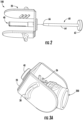
FIG. 1A shows an isometric outer view of a removal system according to the present disclosure in an unfolded configuration; -
FIG. 1B shows an isometric inner view of the removal system ofFIG. 1A ; -
FIG. 1C shows a top-down view of the removal system ofFIG. 1A in a folded configuration; -
FIG. 1D shows an isometric inner view of the removal system ofFIG. 1C . -
FIG. 2 is an exploded view of the removal system ofFIG. 1A . -
FIG. 3A illustrates a step in a method of removing a device from an endoscopic instrument according to the present disclosure; -
FIG. 3B shows a step of securing the endoscopic device to the removal system by inserting an insertion device; and -
FIG. 3C is an isometric inner view of the removal system and endoscopic device ready to be removed. - This description and the accompanying drawings illustrate exemplary embodiments and should not be taken as limiting, with the claims defining the scope of the present disclosure, including equivalents. In some instances, well-known structures and techniques have not been shown or described in detail so as not to obscure the disclosure. Like numbers in two or more figures represent the same or similar elements. Furthermore, elements and their associated aspects that are described in detail with reference to one embodiment may, whenever practical, be included in other embodiments in which they are not specifically shown or described. For example, if an element is described in detail with reference to one embodiment and is not described with reference to a second embodiment, the element may nevertheless be claimed as included in the second embodiment. Moreover, the depictions herein are for illustrative purposes only and do not necessarily reflect the actual shape, size, or dimensions of the system or illustrated components.
- It is noted that, as used in this specification and the appended claims, the singular forms "a," "an," and "the," and any singular use of any word, include plural referents unless expressly and unequivocally limited to one referent. As used herein, the term "include" and its grammatical variants are intended to be nonlimiting, such that recitation of items in a list is not to the exclusion of other like items that can be substituted or added to the listed items.
- The present disclosure provides a system that enables the precise, predictable and less traumatic removal of a variety of devices used in endoscopic procedures. The devices that can be removed include, for example, endoscopic caps, endoscopic shields, sheaths, optical couplers, lenses, variceal banding devices, endoscopic submucosal resection devices, balloons and other such devices that can be placed on, within, or over an endoscope or other devices used endoscopically, interventionally or in other procedures where an instrument or other device is inserted in a body. The present disclosure is particularly useful for removing devices from endoscopes, such as optical couplers and conductive optical elements that may be removably coupled to the distal end portion of an endoscope. Optical coupling devices suitable for removal by the systems and methods of the present invention, for example, are described in International Application Nos:
PCT/US2016/043371, filed July 21, 2016 ,PCT/US2016/035566, filed June 2, 2016 andU.S. Patent No. 8,905,921 . - According to one exemplary embodiment shown in
FIGS. 1A-1D , aremoval system 100 includes aremoval element 20 configured to atraumatically grip and apply force to the outer surface or end of the device being removed, allowing the user to grasp and apply force to the device subject to removal from the endoscope or instrument. Theremoval element 20 comprises anelongate body 22 having acentral portion 24 flanked by adjacent tabs orgripping arms central portion 24 at scoredareas 28. The scoredareas 28 betweencentral portion 24 andgripping arms arms central portion 24, as shown inFIGS. 1C and 1D . Of course, other configurations are possible. For example, grippingarms central portion 24 through a variety of different mechanisms, such as a hinge or other suitable articulation mechanisms. - On the
inner surface 32 of theremoval element 20, surface protrusions, such asridges 36 or other suitable gripping elements, can be provided, as shown inFIG. 1B , to increase the grip and application of force to grasp and remove the device subject to removal. Theremoval element 20 or any other aspect of thesystem 100 may includefinger grip elements 38 on itsouter surface 34, as shown inFIG. 1A , to improve the ergonomic aspects of the system by making it easier to hold and apply force to thesystem 100. In one embodiment,finger grip elements 38 are protrusions extending outwardly fromgripping arms grip elements 38 asremoval element 20 is being pulled in the proximal direction (or the direction opposite the curved surfaces). - According to the present invention, the
system 100 includes aninsertion device 40, as shown inFIG. 2 , which may be a collet or other suitable element capable of being inserted into the working channel of an endoscopic shield, an optical coupler, an endoscopic cap or other device subject to removal that includes an internal channel. Theinsertion device 40 may be attachable to theremoval element 20, so that the insertion element is advanced into the internal channel of the device subject to removal. Alternatively,insertion device 40 may be an integral part of removal element 20 (i.e., manufactured together in the same mold). Theinsertion device 40 preferably comprises anelongate shaft 42 withslits 44 or other suitable cutout or design features that allow theinsertion device 40 to collapse or otherwise reduce the diameter of itselongate shaft 42 upon insertion. This allowsinsertion device 40 to be advanced easily through the internal channel of the device subject to removal. In addition,insertion device 40 will then naturally expand outward within the device to create a friction fit betweeninsertion device 40 and the device to be removed. This friction fit allows the user to apply a force from within the device as it is withdrawn. Applying a force from within the device spreads the application of force so that the force being applied is from the outside of the device (through grippingarms insertion device 40. This reduces the local pressure applied to any one portion of the device, which results in a more precise and atraumatic removal. - It is of course understood that the
removal element 20 may be configured to provide a radial pressure or force from the inside of the device to be removed, or it may be used to spread the ends to capture the device to be removed. In other words, theremoval element 20 may be used to effectively grab and pull the device away from the instrument or endoscope on which it is attached by spreading the opening end and pulling the device towards the user. - In alternative embodiments, the
insertion device 40 comprises a projection (not shown), such as a knob, flange, lip, extension or other protrusion, that can be inserted into an opening in the device to be removed. In these embodiments, the projection is configured to expand outward upon insertion into the opening to create a friction fit within the device. The projection may, for example, comprise a flexible material that is biased outward by a spring or the natural composition of the material. The user may exert force upon the projection to collapse it and insert it into the opening, whereby it then expands outward to create the friction fit. In one such embodiment, the projection is configured to spread outward upon insertion into the opening such that the projection applies force to the inside proximal surface of the device as it is being withdrawn by the user. In these embodiments, theinsertion device 40 may, for example, be used to remove devices that have an opening, but no internal channel therein. - In some embodiments, the
insertion device 40 can have one ormore ridges 48 or other surface features or variations on its outer surface to increase the amount of adhesion and grip in the internal channel when theremoval system 100 is applied to remove the device.Ridges 48 may, for example, be disposed on the outer or distal surfaces ofshaft 42. - As shown in
FIG. 2 , an expandinginstrument 60 may be provided for use with theremoval system 100. According to another aspect of the exemplary embodiment,insertion device 40 may include an opening 46 (seeFIG. 3B ) leading into an internal channel (not shown) withinelongate shaft 42 for receiving expandinginstrument 60. In some embodiments, expandinginstrument 60 has a larger outer diameter than the inner diameter of the internal channel ofinsertion device 40 such that expandinginstrument 60 expandsinsertion device 40. In some cases, the outer diameter of expandinginstrument 60 is only larger than the collapsed internal dimeter of insertion device 40 (i.e., after it has been inserted into device and collapsed due to theslits 44 on shaft 42). In other embodiments, the expandinginstrument 60 may include anenlarged head portion 62 and anelongate shaft 64 extending from thehead portion 62. In these embodiments, theenlarged head portion 62 serves to expand insertion device 40 (i.e., the outer diameter of expandinginstrument 60 may be equal to or less than the inner diameter of insertion device 40). In all of these embodiments, advancinginsertion device 40 throughopening 46 and into the internal channel ofinsertion device 40 increases the diameter ofelongate shaft 42 and therefore the amount of resistance and transfer of force when theinsertion device 40 is used to remove the device subject to removal. - The
elongate shaft 64 of expandinginstrument 60 may terminate in atip 66. In some embodiments, thetip 66 may be tapered and either blunt or sharp.Tip 66 serves to facilitate advancement of expanding instrument through the internal channel ininsertion device 40. - Referring now to
FIGS. 3A-3C , an exemplary method of removing arepresentative device 200 that is attached onto an instrument or endoscope according to the present disclosure will now be described.Insertion device 40 is advanced through an opening and into the interior of device, as shown inFIG. 3C .Slits 44 allowshaft 42 ofinsertion device 40 to collapse to facilitate its advancement through the opening ofdevice 200. The grippingarms removal element 20 may then be folded onto thedevice 200, as shown inFIG. 3A . Theridges 36 on theinner surface 32 of theremoval element 20 may allow a secure grip when the user applies pressure using thefinger grip elements 38 to fold theremoval element 20 over thedevice 200 to be removed. Next, the expandinginstrument 60 may be inserted through opening 46 of theinsertion device 60, as shown inFIG. 3B . This expands the diameter of theelongate shaft 42 of theinsertion device 40 and further secures thedevice 200 within the removal system, as shown inFIG. 3C . Once theinsertion device 60 has been inserted, the user may grip theentire removal system 100 and pull thedevice 200 away from the instrument or endoscope, thereby removing thedevice 200 in a precise, predictable and less traumatic manner than current methods. - The components of the
removal system 100 may be made of any medical grade material, including for example, but not by way of limitation, elastomeric materials, rigid materials, combinations of materials to achieve various performance elements that may include both elastic and rigid materials, which may include polypropylenes, PET materials, PTFE materials, thermoplastic elastomers, polycarbonates, acrylics, and any other elastic or rigid medical grade material. - It is of course understood that the
removal system 100 may be sterilized using any acceptable method or may be non-sterile. For example, theremoval system 100 may be provided as a disposable or single-use system.
Claims (8)
- A system for removing a device from an endoscopic instrument, the system comprising:a removal element for gripping the device, the removal element having a body comprising a central portion and first and second gripping arms coupled to the central portion; andan insertion device coupled to and extending from the central portion of the removal element and having an elongate shaft configured for advancement through an opening within the device into an internal channel in the device,wherein the elongate shaft is collapsible such that an outer diameter of at least a portion of the elongate shaft is reduced upon advancement into the internal channel of the device,characterised in that the first and second gripping arms are pivotally coupled to the central portion.
- The system of claim 1, further comprising an expanding instrument configured for insertion into the insertion device.
- The system of claim 2, wherein the insertion device comprises an internal open channel for receiving the expanding instrument.
- The system of claim 2, wherein the insertion device is expandable upon advancement of the expanding instrument into the internal open channel.
- The system of claim 2, wherein the insertion device comprises slits along the elongate shaft allowing for expansion of the elongate shaft.
- The system of claim 1, wherein the first and second gripping arms include ridges or finger gripping elements on an inner surface.
- The system of claim 1, wherein the insertion device includes ridges on the projection.
- The system of claim 2, wherein the expanding instrument comprises an elongate shaft having an enlarged distal head and terminates in a tapered tip.
Applications Claiming Priority (2)
| Application Number | Priority Date | Filing Date | Title |
|---|---|---|---|
| US201962788901P | 2019-01-06 | 2019-01-06 | |
| PCT/US2020/012251 WO2020142736A1 (en) | 2019-01-06 | 2020-01-03 | Endoscopic device removal system and method |
Publications (3)
| Publication Number | Publication Date |
|---|---|
| EP3905941A1 EP3905941A1 (en) | 2021-11-10 |
| EP3905941A4 EP3905941A4 (en) | 2022-12-28 |
| EP3905941B1 true EP3905941B1 (en) | 2025-03-26 |
Family
ID=71407415
Family Applications (1)
| Application Number | Title | Priority Date | Filing Date |
|---|---|---|---|
| EP20736103.1A Active EP3905941B1 (en) | 2019-01-06 | 2020-01-03 | Endoscopic device removal system |
Country Status (5)
| Country | Link |
|---|---|
| US (2) | US12137875B2 (en) |
| EP (1) | EP3905941B1 (en) |
| JP (2) | JP7526497B2 (en) |
| CA (1) | CA3125490A1 (en) |
| WO (1) | WO2020142736A1 (en) |
Families Citing this family (1)
| Publication number | Priority date | Publication date | Assignee | Title |
|---|---|---|---|---|
| NZ785602A (en) * | 2019-09-11 | 2025-12-19 | Whiteley Corp Pty Ltd | Medical lubricant applicator |
Family Cites Families (15)
| Publication number | Priority date | Publication date | Assignee | Title |
|---|---|---|---|---|
| JPH07199089A (en) * | 1993-12-29 | 1995-08-04 | Olympus Optical Co Ltd | Attaching auxiliary tool for endoscopic device |
| ATE299687T1 (en) | 1996-03-19 | 2005-08-15 | Sherwood Serv Ag | GASTROINTESTINAL TUBE INSERTION OR REMOVAL DEVICE |
| JPH10127578A (en) * | 1996-11-06 | 1998-05-19 | Olympus Optical Co Ltd | Endoscope |
| US7905830B2 (en) * | 2005-05-13 | 2011-03-15 | Ethicon Endo-Surgery, Inc. | Sheath for use with an endoscope |
| US7811251B2 (en) | 2005-10-13 | 2010-10-12 | Tyco Healthcare Group Lp | Trocar anchor |
| WO2008098124A1 (en) * | 2007-02-07 | 2008-08-14 | Boston Scientific Scimed, Inc. | Attachment clamp |
| CN103961049B (en) * | 2008-03-31 | 2017-04-12 | 智能医疗系统有限公司 | Assemblies for use with an endoscope |
| GB0909820D0 (en) | 2009-06-08 | 2009-07-22 | Scopeguard Ltd | Endoscope sheath removal |
| WO2012002091A1 (en) * | 2010-06-28 | 2012-01-05 | オリンパスメディカルシステムズ株式会社 | Forceps for endoscope |
| US20130036586A1 (en) | 2011-08-12 | 2013-02-14 | Fujifilm Corporation | Attachment jig for attaching self-propelled device to endoscope |
| EP2982307A4 (en) * | 2013-11-26 | 2016-11-09 | Olympus Corp | Balloon removing device |
| JP6265827B2 (en) | 2014-05-01 | 2018-01-24 | オリンパス株式会社 | Endoscope optical adapter attachment / detachment aid and endoscope system |
| GB201418173D0 (en) * | 2014-10-14 | 2014-11-26 | Meditech Endoscopy Ltd | Instrument tip protector |
| TW201704292A (en) | 2015-07-20 | 2017-02-01 | 奇美實業股份有限公司 | Liquid crystal alignment agent, liquid crystal alignment film, and liquid crystal display element |
| US10066435B2 (en) | 2016-07-08 | 2018-09-04 | ASSA ABLOY Accessories and Door Conrtols Group, Inc. | Modular door rail |
-
2020
- 2020-01-03 JP JP2021539381A patent/JP7526497B2/en active Active
- 2020-01-03 US US17/420,424 patent/US12137875B2/en active Active
- 2020-01-03 WO PCT/US2020/012251 patent/WO2020142736A1/en not_active Ceased
- 2020-01-03 EP EP20736103.1A patent/EP3905941B1/en active Active
- 2020-01-03 CA CA3125490A patent/CA3125490A1/en active Pending
-
2024
- 2024-07-12 JP JP2024112350A patent/JP7795226B2/en active Active
- 2024-10-09 US US18/910,141 patent/US20250025021A1/en active Pending
Also Published As
| Publication number | Publication date |
|---|---|
| JP7526497B2 (en) | 2024-08-01 |
| US20220079425A1 (en) | 2022-03-17 |
| US12137875B2 (en) | 2024-11-12 |
| EP3905941A4 (en) | 2022-12-28 |
| JP2024128090A (en) | 2024-09-20 |
| JP7795226B2 (en) | 2026-01-07 |
| US20250025021A1 (en) | 2025-01-23 |
| WO2020142736A1 (en) | 2020-07-09 |
| CA3125490A1 (en) | 2020-07-09 |
| JP2022518149A (en) | 2022-03-14 |
| EP3905941A1 (en) | 2021-11-10 |
Similar Documents
| Publication | Publication Date | Title |
|---|---|---|
| JP5383999B2 (en) | Mounting device for endoscope | |
| US5217001A (en) | Endoscope sheath and related method | |
| US6171282B1 (en) | Soft cannula and methods for use | |
| US20100063358A1 (en) | Channeled flexible sleeve for medical articles | |
| EP2292165A2 (en) | A foam port introducer | |
| JP2012130677A (en) | Self-expanding opening part protector for body | |
| US12575717B2 (en) | Device delivery tools and systems | |
| US20250025021A1 (en) | Endoscopic Device Removal System and Method | |
| JP2010172694A (en) | Suture management system for surgical portal apparatus including internal tube | |
| JP2014171629A (en) | Auxiliary tool for endoscope apparatus and endoscope apparatus using the same | |
| US10433869B2 (en) | Percuscopic access device and cleaning obturator | |
| EP3698741A1 (en) | Access assembly including flexible cannula | |
| US20220273339A1 (en) | Cannula for preventing tumor seeding |
Legal Events
| Date | Code | Title | Description |
|---|---|---|---|
| STAA | Information on the status of an ep patent application or granted ep patent |
Free format text: STATUS: THE INTERNATIONAL PUBLICATION HAS BEEN MADE |
|
| PUAI | Public reference made under article 153(3) epc to a published international application that has entered the european phase |
Free format text: ORIGINAL CODE: 0009012 |
|
| STAA | Information on the status of an ep patent application or granted ep patent |
Free format text: STATUS: REQUEST FOR EXAMINATION WAS MADE |
|
| 17P | Request for examination filed |
Effective date: 20210806 |
|
| AK | Designated contracting states |
Kind code of ref document: A1 Designated state(s): AL AT BE BG CH CY CZ DE DK EE ES FI FR GB GR HR HU IE IS IT LI LT LU LV MC MK MT NL NO PL PT RO RS SE SI SK SM TR |
|
| DAV | Request for validation of the european patent (deleted) | ||
| DAX | Request for extension of the european patent (deleted) | ||
| RIC1 | Information provided on ipc code assigned before grant |
Ipc: A61B 1/00 20060101AFI20220822BHEP |
|
| A4 | Supplementary search report drawn up and despatched |
Effective date: 20221125 |
|
| RIC1 | Information provided on ipc code assigned before grant |
Ipc: A61B 1/00 20060101AFI20221121BHEP |
|
| GRAP | Despatch of communication of intention to grant a patent |
Free format text: ORIGINAL CODE: EPIDOSNIGR1 |
|
| STAA | Information on the status of an ep patent application or granted ep patent |
Free format text: STATUS: GRANT OF PATENT IS INTENDED |
|
| INTG | Intention to grant announced |
Effective date: 20241030 |
|
| RAP3 | Party data changed (applicant data changed or rights of an application transferred) |
Owner name: GI SCIENTIFIC, LLC |
|
| GRAS | Grant fee paid |
Free format text: ORIGINAL CODE: EPIDOSNIGR3 |
|
| GRAA | (expected) grant |
Free format text: ORIGINAL CODE: 0009210 |
|
| STAA | Information on the status of an ep patent application or granted ep patent |
Free format text: STATUS: THE PATENT HAS BEEN GRANTED |
|
| AK | Designated contracting states |
Kind code of ref document: B1 Designated state(s): AL AT BE BG CH CY CZ DE DK EE ES FI FR GB GR HR HU IE IS IT LI LT LU LV MC MK MT NL NO PL PT RO RS SE SI SK SM TR |
|
| REG | Reference to a national code |
Ref country code: GB Ref legal event code: FG4D |
|
| REG | Reference to a national code |
Ref country code: CH Ref legal event code: EP |
|
| REG | Reference to a national code |
Ref country code: DE Ref legal event code: R096 Ref document number: 602020048310 Country of ref document: DE |
|
| REG | Reference to a national code |
Ref country code: IE Ref legal event code: FG4D |
|
| PG25 | Lapsed in a contracting state [announced via postgrant information from national office to epo] |
Ref country code: RS Free format text: LAPSE BECAUSE OF FAILURE TO SUBMIT A TRANSLATION OF THE DESCRIPTION OR TO PAY THE FEE WITHIN THE PRESCRIBED TIME-LIMIT Effective date: 20250626 |
|
| PG25 | Lapsed in a contracting state [announced via postgrant information from national office to epo] |
Ref country code: FI Free format text: LAPSE BECAUSE OF FAILURE TO SUBMIT A TRANSLATION OF THE DESCRIPTION OR TO PAY THE FEE WITHIN THE PRESCRIBED TIME-LIMIT Effective date: 20250326 |
|
| REG | Reference to a national code |
Ref country code: LT Ref legal event code: MG9D |
|
| PG25 | Lapsed in a contracting state [announced via postgrant information from national office to epo] |
Ref country code: NO Free format text: LAPSE BECAUSE OF FAILURE TO SUBMIT A TRANSLATION OF THE DESCRIPTION OR TO PAY THE FEE WITHIN THE PRESCRIBED TIME-LIMIT Effective date: 20250626 |
|
| PG25 | Lapsed in a contracting state [announced via postgrant information from national office to epo] |
Ref country code: HR Free format text: LAPSE BECAUSE OF FAILURE TO SUBMIT A TRANSLATION OF THE DESCRIPTION OR TO PAY THE FEE WITHIN THE PRESCRIBED TIME-LIMIT Effective date: 20250326 |
|
| PG25 | Lapsed in a contracting state [announced via postgrant information from national office to epo] |
Ref country code: LV Free format text: LAPSE BECAUSE OF FAILURE TO SUBMIT A TRANSLATION OF THE DESCRIPTION OR TO PAY THE FEE WITHIN THE PRESCRIBED TIME-LIMIT Effective date: 20250326 |
|
| PG25 | Lapsed in a contracting state [announced via postgrant information from national office to epo] |
Ref country code: GR Free format text: LAPSE BECAUSE OF FAILURE TO SUBMIT A TRANSLATION OF THE DESCRIPTION OR TO PAY THE FEE WITHIN THE PRESCRIBED TIME-LIMIT Effective date: 20250627 Ref country code: BG Free format text: LAPSE BECAUSE OF FAILURE TO SUBMIT A TRANSLATION OF THE DESCRIPTION OR TO PAY THE FEE WITHIN THE PRESCRIBED TIME-LIMIT Effective date: 20250326 |
|
| REG | Reference to a national code |
Ref country code: NL Ref legal event code: MP Effective date: 20250326 |
|
| PG25 | Lapsed in a contracting state [announced via postgrant information from national office to epo] |
Ref country code: NL Free format text: LAPSE BECAUSE OF FAILURE TO SUBMIT A TRANSLATION OF THE DESCRIPTION OR TO PAY THE FEE WITHIN THE PRESCRIBED TIME-LIMIT Effective date: 20250326 |
|
| PG25 | Lapsed in a contracting state [announced via postgrant information from national office to epo] |
Ref country code: SE Free format text: LAPSE BECAUSE OF FAILURE TO SUBMIT A TRANSLATION OF THE DESCRIPTION OR TO PAY THE FEE WITHIN THE PRESCRIBED TIME-LIMIT Effective date: 20250326 |
|
| REG | Reference to a national code |
Ref country code: AT Ref legal event code: MK05 Ref document number: 1778191 Country of ref document: AT Kind code of ref document: T Effective date: 20250326 |
|
| PG25 | Lapsed in a contracting state [announced via postgrant information from national office to epo] |
Ref country code: SM Free format text: LAPSE BECAUSE OF FAILURE TO SUBMIT A TRANSLATION OF THE DESCRIPTION OR TO PAY THE FEE WITHIN THE PRESCRIBED TIME-LIMIT Effective date: 20250326 |
|
| PG25 | Lapsed in a contracting state [announced via postgrant information from national office to epo] |
Ref country code: PT Free format text: LAPSE BECAUSE OF FAILURE TO SUBMIT A TRANSLATION OF THE DESCRIPTION OR TO PAY THE FEE WITHIN THE PRESCRIBED TIME-LIMIT Effective date: 20250728 Ref country code: ES Free format text: LAPSE BECAUSE OF FAILURE TO SUBMIT A TRANSLATION OF THE DESCRIPTION OR TO PAY THE FEE WITHIN THE PRESCRIBED TIME-LIMIT Effective date: 20250326 |
|
| PG25 | Lapsed in a contracting state [announced via postgrant information from national office to epo] |
Ref country code: IT Free format text: LAPSE BECAUSE OF FAILURE TO SUBMIT A TRANSLATION OF THE DESCRIPTION OR TO PAY THE FEE WITHIN THE PRESCRIBED TIME-LIMIT Effective date: 20250326 Ref country code: PL Free format text: LAPSE BECAUSE OF FAILURE TO SUBMIT A TRANSLATION OF THE DESCRIPTION OR TO PAY THE FEE WITHIN THE PRESCRIBED TIME-LIMIT Effective date: 20250326 |
|
| PG25 | Lapsed in a contracting state [announced via postgrant information from national office to epo] |
Ref country code: AT Free format text: LAPSE BECAUSE OF FAILURE TO SUBMIT A TRANSLATION OF THE DESCRIPTION OR TO PAY THE FEE WITHIN THE PRESCRIBED TIME-LIMIT Effective date: 20250326 |
|
| PG25 | Lapsed in a contracting state [announced via postgrant information from national office to epo] |
Ref country code: EE Free format text: LAPSE BECAUSE OF FAILURE TO SUBMIT A TRANSLATION OF THE DESCRIPTION OR TO PAY THE FEE WITHIN THE PRESCRIBED TIME-LIMIT Effective date: 20250326 |
|
| PG25 | Lapsed in a contracting state [announced via postgrant information from national office to epo] |
Ref country code: RO Free format text: LAPSE BECAUSE OF FAILURE TO SUBMIT A TRANSLATION OF THE DESCRIPTION OR TO PAY THE FEE WITHIN THE PRESCRIBED TIME-LIMIT Effective date: 20250326 |
|
| PG25 | Lapsed in a contracting state [announced via postgrant information from national office to epo] |
Ref country code: SK Free format text: LAPSE BECAUSE OF FAILURE TO SUBMIT A TRANSLATION OF THE DESCRIPTION OR TO PAY THE FEE WITHIN THE PRESCRIBED TIME-LIMIT Effective date: 20250326 |
|
| PG25 | Lapsed in a contracting state [announced via postgrant information from national office to epo] |
Ref country code: IS Free format text: LAPSE BECAUSE OF FAILURE TO SUBMIT A TRANSLATION OF THE DESCRIPTION OR TO PAY THE FEE WITHIN THE PRESCRIBED TIME-LIMIT Effective date: 20250726 |
|
| REG | Reference to a national code |
Ref country code: DE Ref legal event code: R097 Ref document number: 602020048310 Country of ref document: DE |
|
| PG25 | Lapsed in a contracting state [announced via postgrant information from national office to epo] |
Ref country code: DK Free format text: LAPSE BECAUSE OF FAILURE TO SUBMIT A TRANSLATION OF THE DESCRIPTION OR TO PAY THE FEE WITHIN THE PRESCRIBED TIME-LIMIT Effective date: 20250326 |
|
| PG25 | Lapsed in a contracting state [announced via postgrant information from national office to epo] |
Ref country code: CZ Free format text: LAPSE BECAUSE OF FAILURE TO SUBMIT A TRANSLATION OF THE DESCRIPTION OR TO PAY THE FEE WITHIN THE PRESCRIBED TIME-LIMIT Effective date: 20250326 |
|
| PLBE | No opposition filed within time limit |
Free format text: ORIGINAL CODE: 0009261 |
|
| STAA | Information on the status of an ep patent application or granted ep patent |
Free format text: STATUS: NO OPPOSITION FILED WITHIN TIME LIMIT |
|
| REG | Reference to a national code |
Ref country code: CH Ref legal event code: L10 Free format text: ST27 STATUS EVENT CODE: U-0-0-L10-L00 (AS PROVIDED BY THE NATIONAL OFFICE) Effective date: 20260211 |
|
| 26N | No opposition filed |
Effective date: 20260105 |
|
| PGFP | Annual fee paid to national office [announced via postgrant information from national office to epo] |
Ref country code: GB Payment date: 20260130 Year of fee payment: 7 |
|
| PGFP | Annual fee paid to national office [announced via postgrant information from national office to epo] |
Ref country code: DE Payment date: 20260130 Year of fee payment: 7 |
|
| PGFP | Annual fee paid to national office [announced via postgrant information from national office to epo] |
Ref country code: FR Payment date: 20260130 Year of fee payment: 7 |