EP3905803A1 - Data transmission method, base station, user equipment and storage medium - Google Patents
Data transmission method, base station, user equipment and storage medium Download PDFInfo
- Publication number
- EP3905803A1 EP3905803A1 EP18944164.5A EP18944164A EP3905803A1 EP 3905803 A1 EP3905803 A1 EP 3905803A1 EP 18944164 A EP18944164 A EP 18944164A EP 3905803 A1 EP3905803 A1 EP 3905803A1
- Authority
- EP
- European Patent Office
- Prior art keywords
- tci
- signaling
- tbs
- user equipment
- panels
- Prior art date
- Legal status (The legal status is an assumption and is not a legal conclusion. Google has not performed a legal analysis and makes no representation as to the accuracy of the status listed.)
- Pending
Links
Images




Classifications
-
- H—ELECTRICITY
- H04—ELECTRIC COMMUNICATION TECHNIQUE
- H04W—WIRELESS COMMUNICATION NETWORKS
- H04W72/00—Local resource management
- H04W72/20—Control channels or signalling for resource management
- H04W72/23—Control channels or signalling for resource management in the downlink direction of a wireless link, i.e. towards a terminal
- H04W72/231—Control channels or signalling for resource management in the downlink direction of a wireless link, i.e. towards a terminal the control data signalling from the layers above the physical layer, e.g. RRC or MAC-CE signalling
-
- H—ELECTRICITY
- H04—ELECTRIC COMMUNICATION TECHNIQUE
- H04W—WIRELESS COMMUNICATION NETWORKS
- H04W72/00—Local resource management
- H04W72/04—Wireless resource allocation
- H04W72/044—Wireless resource allocation based on the type of the allocated resource
- H04W72/046—Wireless resource allocation based on the type of the allocated resource the resource being in the space domain, e.g. beams
-
- H—ELECTRICITY
- H04—ELECTRIC COMMUNICATION TECHNIQUE
- H04B—TRANSMISSION
- H04B7/00—Radio transmission systems, i.e. using radiation field
- H04B7/02—Diversity systems; Multi-antenna system, i.e. transmission or reception using multiple antennas
- H04B7/04—Diversity systems; Multi-antenna system, i.e. transmission or reception using multiple antennas using two or more spaced independent antennas
- H04B7/0408—Diversity systems; Multi-antenna system, i.e. transmission or reception using multiple antennas using two or more spaced independent antennas using two or more beams, i.e. beam diversity
-
- H—ELECTRICITY
- H04—ELECTRIC COMMUNICATION TECHNIQUE
- H04B—TRANSMISSION
- H04B7/00—Radio transmission systems, i.e. using radiation field
- H04B7/02—Diversity systems; Multi-antenna system, i.e. transmission or reception using multiple antennas
- H04B7/04—Diversity systems; Multi-antenna system, i.e. transmission or reception using multiple antennas using two or more spaced independent antennas
- H04B7/06—Diversity systems; Multi-antenna system, i.e. transmission or reception using multiple antennas using two or more spaced independent antennas at the transmitting station
- H04B7/0686—Hybrid systems, i.e. switching and simultaneous transmission
- H04B7/0695—Hybrid systems, i.e. switching and simultaneous transmission using beam selection
- H04B7/06952—Selecting one or more beams from a plurality of beams, e.g. beam training, management or sweeping
- H04B7/06966—Selecting one or more beams from a plurality of beams, e.g. beam training, management or sweeping using beam correspondence; using channel reciprocity, e.g. downlink beam training based on uplink sounding reference signal [SRS]
-
- H—ELECTRICITY
- H04—ELECTRIC COMMUNICATION TECHNIQUE
- H04B—TRANSMISSION
- H04B7/00—Radio transmission systems, i.e. using radiation field
- H04B7/02—Diversity systems; Multi-antenna system, i.e. transmission or reception using multiple antennas
- H04B7/04—Diversity systems; Multi-antenna system, i.e. transmission or reception using multiple antennas using two or more spaced independent antennas
- H04B7/08—Diversity systems; Multi-antenna system, i.e. transmission or reception using multiple antennas using two or more spaced independent antennas at the receiving station
- H04B7/0868—Hybrid systems, i.e. switching and combining
- H04B7/088—Hybrid systems, i.e. switching and combining using beam selection
-
- H—ELECTRICITY
- H04—ELECTRIC COMMUNICATION TECHNIQUE
- H04L—TRANSMISSION OF DIGITAL INFORMATION, e.g. TELEGRAPHIC COMMUNICATION
- H04L5/00—Arrangements affording multiple use of the transmission path
- H04L5/003—Arrangements for allocating sub-channels of the transmission path
- H04L5/0044—Allocation of payload; Allocation of data channels, e.g. PDSCH or PUSCH
-
- H—ELECTRICITY
- H04—ELECTRIC COMMUNICATION TECHNIQUE
- H04L—TRANSMISSION OF DIGITAL INFORMATION, e.g. TELEGRAPHIC COMMUNICATION
- H04L5/00—Arrangements affording multiple use of the transmission path
- H04L5/003—Arrangements for allocating sub-channels of the transmission path
- H04L5/0053—Allocation of signalling, i.e. of overhead other than pilot signals
-
- H—ELECTRICITY
- H04—ELECTRIC COMMUNICATION TECHNIQUE
- H04L—TRANSMISSION OF DIGITAL INFORMATION, e.g. TELEGRAPHIC COMMUNICATION
- H04L5/00—Arrangements affording multiple use of the transmission path
- H04L5/0091—Signalling for the administration of the divided path, e.g. signalling of configuration information
-
- H—ELECTRICITY
- H04—ELECTRIC COMMUNICATION TECHNIQUE
- H04W—WIRELESS COMMUNICATION NETWORKS
- H04W72/00—Local resource management
- H04W72/12—Wireless traffic scheduling
- H04W72/1263—Mapping of traffic onto schedule, e.g. scheduled allocation or multiplexing of flows
- H04W72/1273—Mapping of traffic onto schedule, e.g. scheduled allocation or multiplexing of flows of downlink data flows
-
- H—ELECTRICITY
- H04—ELECTRIC COMMUNICATION TECHNIQUE
- H04W—WIRELESS COMMUNICATION NETWORKS
- H04W72/00—Local resource management
- H04W72/20—Control channels or signalling for resource management
- H04W72/23—Control channels or signalling for resource management in the downlink direction of a wireless link, i.e. towards a terminal
-
- H—ELECTRICITY
- H04—ELECTRIC COMMUNICATION TECHNIQUE
- H04W—WIRELESS COMMUNICATION NETWORKS
- H04W72/00—Local resource management
- H04W72/20—Control channels or signalling for resource management
- H04W72/23—Control channels or signalling for resource management in the downlink direction of a wireless link, i.e. towards a terminal
- H04W72/232—Control channels or signalling for resource management in the downlink direction of a wireless link, i.e. towards a terminal the control data signalling from the physical layer, e.g. DCI signalling
-
- H—ELECTRICITY
- H04—ELECTRIC COMMUNICATION TECHNIQUE
- H04W—WIRELESS COMMUNICATION NETWORKS
- H04W76/00—Connection management
- H04W76/20—Manipulation of established connections
- H04W76/27—Transitions between radio resource control [RRC] states
-
- H—ELECTRICITY
- H04—ELECTRIC COMMUNICATION TECHNIQUE
- H04L—TRANSMISSION OF DIGITAL INFORMATION, e.g. TELEGRAPHIC COMMUNICATION
- H04L5/00—Arrangements affording multiple use of the transmission path
- H04L5/0001—Arrangements for dividing the transmission path
- H04L5/0014—Three-dimensional division
- H04L5/0023—Time-frequency-space
Definitions
- the present disclosure relates to the field of communication technologies, and more particularly, to a method for data transmission, a base station, user equipment, and a storage medium.
- NR New Radio
- FR2 Frequency Range 2
- TCI Transmission Configuration Indication
- RS Reference Signal
- SSB Synchronization Signal Block
- the base station indicates only one beam direction through signaling. For example, for a reception process of Physical Downlink Shared Channel (PDSCH), different Transport Blocks (TBs) are transmitted by the same panel of the same Transmission Reception Point (TRP), so that the TCI states used by the different TBs are the same. That is, the base station notifies the user equipment to receive these TBs through the same receiving beam.
- PDSCH Physical Downlink Shared Channel
- TRP Transmission Reception Point
- MIMO Multiple-Input Multiple-Output
- the present disclosure provides a method for data transmission, a base station, user equipment, and a storage medium, which enable data transmission between the base station and the user equipment through multiple beams.
- a method for data transmission applied to a base station includes the following operations.
- the base station generates a signaling indicating at least two receiving beams of user equipment.
- the signaling includes TCI states of multiple TBs, the multiple TBs are transmitted by at least two panels, the at least two panels are different panels from the same TRP or panels from different TRPs, and the multiple TBs correspond to the at least two receiving beams of the user equipment.
- the base station transmits the signaling to the user equipment, such that the user equipment determines a respective receiving beam for receiving each of the multiple TBs according to the signaling and receives the TB through the determined respective receiving beam.
- the method further includes the following operations.
- the base station generates a Radio Resource Control (RRC) signaling.
- RRC Radio Resource Control
- the RRC signaling indicates a TCI state group, multiple TCI states included in the TCI state group are divided into at least two TCI state subgroups, and each of the at least two panels corresponds to a respective one of the at least two TCI state subgroups.
- the base station generates a Media Access Control (MAC) signaling.
- MAC Media Access Control
- the MAC signaling indicates activation of M TCI states in each of the TCI state subgroups.
- the operation that the base station generates a signaling indicating at least two receiving beams of user equipment includes the following operations.
- the base station generates a first Downlink Control Information (DCI) signaling that includes at least two TCI fields.
- DCI Downlink Control Information
- the multiple TBs correspond to the at least two TCI fields, and one of the TCI fields indicates TCI states of one or at least two TBs among the multiple TBs.
- the first DCI signaling indicates one TCI state in every M TCI states.
- the operation that the base station generates a signaling indicating at least two receiving beams of user equipment includes the following operations.
- the base station generates a second DCI signaling that includes one TCI field.
- the multiple TBs correspond to the one TCI field, and a part of bits in the one TCI field indicate TCI states of one or at least two TBs among the multiple TBs.
- the second DCI signaling indicates one TCI state in every M TCI states.
- the method further includes the following operations.
- the base station generates at least two RRC signalings.
- each of the at least two RRC signalings indicates a respective one of TCI state groups
- each of the TCI state groups includes multiple TCI states
- each of the at least two panels corresponds to a respective one of the TCI state groups.
- the base station generates at least two MAC signalings.
- each of the at least two MAC signalings indicates activation of N TCI states in a respective one of the TCI state groups.
- the operation that the base station generates a signaling indicating at least two receiving beams of user equipment includes the following operations.
- the base station generates a first DCI signaling that includes at least two TCI fields.
- the multiple TBs correspond to the at least two TCI fields, and one of the TCI fields indicates TCI states of one or at least two TBs among the multiple TBs.
- the first DCI signaling indicates one TCI state in every N TCI states.
- the operation that the base station generates a signaling indicating at least two receiving beams of user equipment includes the following operations.
- the base station generates a second DCI signaling that includes one TCI field.
- the multiple TBs correspond to the one TCI field, and a part of bits in the one TCI field indicate TCI states of one or at least two TBs among the multiple TBs.
- the second DCI signaling indicates one TCI state in every N TCI states.
- a method for data transmission applied to user equipment includes the following operations.
- the user equipment receives, from a base station, a signaling indicating at least two receiving beams of the user equipment.
- the signaling includes TCI states of multiple TBs, the multiple TBs are transmitted by at least two panels, the at least two panels are different panels from the same TRP or panels from different TRPs, and the multiple TBs correspond to the at least two receiving beams of the user equipment.
- the user equipment determines a respective receiving beam for receiving each of the multiple TBs according to the signaling, and receives the TB through the determined respective receiving beam.
- an apparatus for data transmission for use in a base station.
- the apparatus includes a first generation module and a transmitting module.
- the first generation module is configured to generate a signaling indicating at least two receiving beams of user equipment, here, the signaling includes TCI states of multiple TBs, the multiple TBs are transmitted by at least two panels, the at least two panels are different panels from the same TRP or panels from different TRPs, and the multiple TBs correspond to the at least two receiving beams of the user equipment.
- the transmitting module is configured to transmit the signaling to the user equipment, such that the user equipment determines a respective receiving beam for receiving each of the multiple TBs according to the signaling and receives the TB through the determined respective receiving beam.
- the apparatus further includes a second generation module and a third generation module.
- the second generation module is configured to generate a RRC signaling, herein, the RRC signaling indicates a TCI state group, multiple TCI states included in the TCI state group are divided into at least two TCI state subgroups, and each of the at least two panels correspond to a respective one of the at least two TCI state subgroups.
- the third generation module is configured to generate a MAC signaling, here, the MAC signaling indicates activation of M TCI states in each of the TCI state subgroups.
- the first generation module is further configured to generate a first DCI signaling that includes at least two TCI fields.
- the multiple TBs correspond to the at least two TCI fields, and one of the TCI fields indicates TCI states of one or at least two TBs among the multiple TBs.
- the first DCI signaling indicates one TCI state in every M TCI states.
- the first generation module is further configured to generate a second DCI signaling that includes one TCI field.
- the multiple TBs correspond to the one TCI field, and a part of bits in the one TCI field indicate TCI states of one or at least two TBs among the multiple TBs.
- the second DCI signaling indicates one TCI state in every M TCI states.
- the apparatus further includes a second generation module and a third generation module.
- the second generation module is configured to generate at least two RRC signalings, here, each of the at least two RRC signalings indicates a respective one of TCI state groups, each of the TCI state groups includes multiple TCI states, and each of the at least two panels correspond to a respective one of the TCI state groups.
- the third generation module is configured to generate at least two MAC signalings, here, each of the MAC signalings indicates activation of N TCI states in a respective one of the TCI state groups.
- the first generation module is further configured to generate a first DCI signaling that includes at least two TCI fields.
- the multiple TBs correspond to the at least two TCI fields, and one of the TCI fields indicates TCI states of one or at least two TBs among the multiple TBs.
- the first DCI signaling indicates one TCI state in every N TCI states.
- the first generation module is further configured to generate a second DCI signaling that includes one TCI field.
- the multiple TBs correspond to the one TCI field, and a part of bits in the one TCI field indicate TCI states of one or at least two TBs among the multiple TBs.
- the second DCI signaling indicates one TCI state in every N TCI states.
- an apparatus for data transmission for use in user equipment.
- the apparatus includes a first receiving module and a second receiving module.
- the first receiving module is configured to receive, from a base station, a signaling indicating at least two receiving beams of the user equipment, here, the signaling includes TCI states of multiple TBs, the multiple TBs are transmitted by at least two panels, the at least two panels are different panels from the same TRP or panels from different TRPs, and the multiple TBs correspond to the at least two receiving beams of the user equipment.
- the second receiving module is configured to determine a respective receiving beam for receiving each of the multiple TBs according to the signaling and receive the TB through the determined respective receiving beam.
- a base station includes a processor and a memory for storing instructions executable by the processor.
- the processor is configured to: generate a signaling indicating at least two receiving beams of user equipment, here, the signaling includes TCI states of multiple TBs, the multiple TBs are transmitted by at least two panels, the at least two panels are different panels from the same TRP or panels from different TRPs, and the multiple TBs correspond to the at least two receiving beams of the user equipment; and transmit the signaling to the user equipment, such that the user equipment determines a respective receiving beam for receiving each of the multiple TBs according to the signaling and receives the TB through the determined respective receiving beam.
- the signaling includes TCI states of multiple TBs
- the multiple TBs are transmitted by at least two panels
- the at least two panels are different panels from the same TRP or panels from different TRPs
- the multiple TBs correspond to the at least two receiving beams of the user equipment
- the user equipment includes a processor and a memory for storing instructions executable by the processor.
- the processor is configured to: receive, from a base station, a signaling indicating at least two receiving beams of the user equipment, here, the signaling includes TCI states of multiple TBs, the multiple TBs are transmitted by at least two panels, the at least two panels are different panels from the same TRP or panels from different TRPs, and the multiple TBs correspond to the at least two receiving beams of the user equipment; and determine a respective receiving beam for receiving each of the multiple TBs according to the signaling, and receive the TB through the determined respective receiving beam.
- a computer-readable storage medium having stored thereon at least one instruction, the at least one instruction is loaded and executed by a processor to perform the operations in the method for data transmission according to the above first aspect.
- a computer-readable storage medium having stored thereon at least one instruction, the at least one instruction is loaded and executed by a processor to perform operations in the method for data transmission according to the above second aspect.
- a base station in the embodiments of the present disclosure transmits to user equipment a signaling indicating at least two receiving beams, here, the signaling includes TCI states of multiple TBs, the multiple TBs are transmitted by at least two panels, the at least two panels are different panels from the same TRP or panels from different TRPs, and the multiple TBs correspond to the at least two receiving beams of the user equipment, so that the user equipment, after receiving the signaling, determines a respective receiving beam for receiving each of the multiple TBs according to the signaling, and receives the TB through the determined respective receiving beam.
- the signaling includes TCI states of multiple TBs
- the multiple TBs are transmitted by at least two panels
- the at least two panels are different panels from the same TRP or panels from different TRPs
- the multiple TBs correspond to the at least two receiving beams of the user equipment, so that the user equipment, after receiving the signaling, determines a respective receiving beam for receiving each of the multiple TBs according to the signaling, and receives
- the embodiments of the present disclosure design new signaling that enables the user equipment to use the multiple receiving beams for data reception when the base station transmits the data through the multiple transmitting beams.
- Such a method for data transmission can be suitable for data transmission based on the multiple TRPs or the multiple panels, and make it possible to perform data transmission between the base station and the user equipment through multiple beams.
- FIG. 1 is a diagram of an implementation environment involved in a method for data transmission according to an exemplary embodiment. As illustrated in FIG. 1 , the implementation environment includes a base station 101 and user equipment 102, and the base station 101 and the user equipment 102 are connected through a communication network.
- the TCI state is used for notifying the user equipment 102 of a receiving beam to be used when receiving the Physical Downlink Control Channel (PDCCH)/PDSCH, and the receiving beam is the same as a receiving beam for receiving a certain SSB or a certain CSI-RS transmitted by the base station.
- the base station 101 indicates, through the TCI field in the DCI signaling, the receiving beam to be used when the user equipment 102 receives the TB transmitted in the PDSCH.
- the base station 101 indicates only one receiving beam direction through DCI signaling.
- the TCI states corresponding to the two TBs are consistent since the two TBs are transmitted by the same panel of the same TRP.
- the corresponding DCI signaling can be as follows.
- TB1 and TB2 correspond to the same TCI state. That is, the base station 101 notifies the user equipment 102 to receive the two TBs through the same receiving beam. Further, in order to clarify how the base station 101 indicates one receiving beam of the user equipment 102, an example of a reception process of PDSCH is described below. 1.
- the base station 101 generates a RRC signaling, and indicates multiple TCI states through the RRC signaling. Herein, the number of the multiple TCI states may be up to 64 or up to 128, which is not specifically limited in the embodiment of the present disclosure. 2.
- the base station 101 generates a MAC signaling, and indicates activation of a part of the TCI states in the RRC signaling through the MAC signaling.
- the number of the part of the TCI states may be 8, and this embodiment of the present disclosure is not specifically limited thereto.
- the base station 101 may not need to generate the MAC signaling. 3.
- the base station 101 generates a DCI signaling, and indicates, through the DCI signaling, one of multiple TCI states activated by the MAC signaling, for use by the user equipment 102 to receive the PDSCH. That is, the base station 101 notifies the user equipment 102 to use one receiving beam to receive all TBs included in the PDSCH. 4.
- the base station 101 transmits the DCI signaling to the user equipment 102, and the DCI signaling indicates the receiving beam, which used in receiving the RS corresponding to the RS identifier included in the TCI state, used by the user equipment 102 to receive the PDSCH.
- Table 1 TCI state RS index Remarks TCI#0 SSB index#1 If the base station notifies UE to use the TCI#0, this means that the base station notifies the UE to use the receiving beam used in receiving the SSB index#1 to receive the PDSCH.
- TCI#1 SSB index#2 TCI#2 CSI-RS index#5 TCI#3 CSI-RS index#6 ... ... ... ... ...
- the above description is directed to a single receiving beam direction.
- future MIMO needs to support data transmission based on multiple TRPs or multiple panels. That is to say, the base station 101 needs to use multiple transmitting beams for data transmission, and correspondingly, the user equipment 102 needs to use multiple receiving beams for data reception. Therefore, it becomes a problem to be solved in the embodiments of the present disclosure that how to indicate the TCI states.
- the data transmission between the base station 101 and the user equipment 102 through multiple beams is explained in detail based on the following embodiments.
- FIG. 2 is a flowchart of a method for data transmission according to an exemplary embodiment. As illustrated in FIG. 2 , the method is applied to a base station, and includes the following operations.
- the base station generates a signaling indicating at least two receiving beams of user equipment, here, the signaling includes TCI states of multiple TBs, the multiple TBs are transmitted by at least two panels, the at least two panels are different panels from the same TRP or panels from different TRPs, and the multiple TBs correspond to the at least two receiving beams of the user equipment.
- the base station transmits the signaling to the user equipment, such that the user equipment determines a respective receiving beam for receiving each of the multiple TBs according to the signaling and receives the TB through the determined respective receiving beam.
- a base station transmits a signaling indicating at least two receiving beams to user equipment during data transmission, here, the signaling includes TCI states of multiple TBs, the multiple TBs are transmitted by at least two panels, the at least two panels are different panels from the same TRP or panels from different TRPs, and the multiple TBs correspond to the at least two receiving beams of the user equipment.
- the user equipment after receiving the signaling, determines a respective receiving beam for receiving each of the multiple TBs according to the signaling, and receives the TB through the determined respective receiving beam.
- the embodiment of the present disclosure designs new signaling that enables the user equipment to use the multiple receiving beams for data reception when the base station transmits data through the multiple transmitting beam directions.
- Such a method for data transmission can be suitable for data transmission based on the multiple TRPs or the multiple panels, and make it possible to perform data transmission between the base station and the user equipment through multiple beams.
- the method further includes the following operations.
- the base station generates a RRC signaling indicating a TCI state group, here, multiple TCI states included in the TCI state group are divided into at least two TCI state subgroups, and each of the at least two panels corresponds to a respective one of the TCI state subgroups.
- the base station generates a MAC signaling indicating activation of M TCI states in each of the TCI state subgroups.
- the operation that the base station generates a signaling indicating at least two receiving beams of user equipment includes the following operations.
- the base station generates a first DCI signaling including at least two TCI fields.
- the multiple TBs correspond to the at least two TCI fields, and one of the TCI fields is used for indicating TCI states of one or at least two TBs among the multiple TBs.
- the first DCI signaling is used for indicating one TCI state in every M TCI states.
- the operation that the base station generates a signaling indicating at least two receiving beams of user equipment includes the following operations.
- the base station generates a second DCI signaling including one TCI field.
- the multiple TBs correspond to the one TCI field, and a part of bits in the one TCI field are used for indicating TCI states of one or at least two TBs among the multiple TBs.
- the second DCI signaling is used for indicating one TCI state in every M TCI states.
- the method further includes the following operations.
- each of the at least two RRC signalings indicates a respective one of TCI state groups, each of the TCI state groups includes multiple TCI states, and each of the at least two panels corresponds to a respective one of the TCI state groups.
- the base station generates at least two MAC signalings, here, each of the at least two MAC signalings is used for indicating activation of N TCI states in a respective one of the TCI state groups.
- the operation that the base station generates a signaling indicating at least two receiving beams of user equipment includes the following operations.
- the base station generates a first DCI signaling including at least two TCI fields.
- the multiple TBs correspond to the at least two TCI fields, and one of the TCI fields is used for indicating TCI states of one or at least two TBs among the multiple TBs.
- the first DCI signaling is used for indicating one TCI state in every N TCI states.
- the operation that the base station generates a signaling indicating at least two receiving beams of user equipment includes the following operations.
- the base station generates a second DCI signaling including one TCI field.
- the multiple TBs correspond to the one TCI field, and a part of bits in the one TCI field are used for indicating TCI states of one or at least two TBs among the multiple TBs.
- the second DCI signaling is used for indicating one TCI state in every N TCI states.
- FIG. 3 is a flowchart of a method for data transmission according to an exemplary embodiment. As illustrated in FIG. 3 , the method is applied to user equipment, and includes the following operations.
- the user equipment receives, from a base station, a signaling for indicating at least two receiving beams of the user equipment, here, the signaling includes TCI states of multiple TBs, the multiple TBs are transmitted by at least two panels, the at least two panels are different panels from the same TRP or panels from different TRPs, and the multiple TBs correspond to the at least two receiving beams of the user equipment.
- the user equipment determines a respective receiving beam for receiving each of the multiple TBs according to the signaling, and receives the TB through the determined respective receiving beam.
- a base station transmits a signaling indicating at least two receiving beams to user equipment during data transmission, here, the signaling includes TCI states of multiple TBs, the multiple TBs are transmitted by at least two panels, the at least two panels are different panels from the same TRP or panels from different TRPs, and the multiple TBs correspond to the at least two receiving beams of the user equipment.
- the user equipment upon reception of the signaling, determines a respective receiving beam for receiving each of the multiple TBs according to the signaling, and receives the TB through the determined respective receiving beam.
- the embodiment of the present disclosure designs new signaling that enables the user equipment to use the multiple receiving beams for data reception when the base station transmits data through the multiple transmitting beam directions.
- Such a method for data transmission can be suitable for data transmission based on the multiple TRPs or the multiple panels, and make it possible to perform data transmission between the base station and the user equipment through multiple beams.
- FIG. 4 is a flowchart of a method for data transmission according to an exemplary embodiment. As illustrated in FIG. 4 , the interaction subjects are a base station and user equipment, and the method for data transmission includes the following operations.
- the base station generates a RRC signaling indicating a TCI state group, herein, multiple TCI states included in the TCI state group are divided into at least two TCI state subgroups.
- each of at least two panels for transmitting multiple TBs corresponds to a respective one of the at least two TCI state subgroups.
- the multiple TBs are transmitted through PDSCH, which is not specifically limited in the embodiment of the present disclosure.
- the at least two panels are different panels from the same TRP or panels from different TRPs, to enable the base station to transmit data through multiple beam directions.
- the number of TBs to be transmitted is 3.
- two of the three TBs are transmitted by one panel and the other of the three TBs is transmitted by the other panel; and these two panels for transmitting the three TBs are either different panels from the same TRP, or panels from two TRPs respectively.
- the TBs transmitted by the different panels are received by the user equipment through different receiving beams. Therefore, each of the at least two panels corresponds to a respective one of the TCI state subgroups.
- each of the three TBs can also be transmitted by a different panel; and these three panels for transmitting the three TBs are either different panels from the same TRP, or panels from three TRPs respectively.
- the number of TCI states indicated by the RRC signaling may be not less than 64 and not greater than 128 in a case that the base station transmits two TBs through two transmitting beams, so as to form a TCI state group.
- the first X TCI states correspond to one panel, and form a TCI state subgroup; the next Y TCI states correspond to the other panel, and form the other TCI state subgroup.
- the TCI state group may be as follows.
- the X+Y TCI states included in the TCI state group are divided into two TCI state subgroups, where TCI#0 to TCI#X-1 form one TCI state subgroup, and TCI#X to TCI#X+Y-1 form the other TCI state subgroup.
- TCI#0 to TCI#X-1 form one TCI state subgroup
- TCI#X to TCI#X+Y-1 form the other TCI state subgroup.
- the values of X and Y are both 64, TCI#0 to TCI#63 form one TCI state subgroup corresponding to one panel; TCI#64 to TCI#127 form the other TCI state subgroup corresponding to the other panel.
- the base station generates a MAC signaling, herein, the MAC signaling is used for indicating activation of M TCI states in each of the TCI state subgroups.
- the activation of the TCI states is indicated collectively by a single MAC signaling.
- the value of M is a positive integer.
- the value of M may be 8, or the value of M may be different for different TCI state subgroups.
- the value of M is 8 for the TCI state subgroup #1, and the value of M is 6 for the TCI state subgroup #2, which are not specifically limited in the embodiment of the present disclosure.
- the MAC signaling can indicate to activate 16 TCI states among X+Y TCI states indicated by the RRC signaling, and the 16 TCI states may not be from the same TCI state subgroup.
- 8 TCI states among the 16 TCI states are from one TCI state subgroup and the remaining 8 TCI states among the 16 TCI states are from the other TCI state subgroup. Accordingly, the MAC signaling for indicating the activation of the TCI states needs to occupy X+Y bits.
- the MAC CE (Control Element) also needs to indicate a serving cell ID, a BWP (Bandwidth Part) ID, and the like.
- the TCI states activated by indication of the MAC signaling need to be from the respective TCI state subgroups.
- all the TCI states activated by indication of the MAC signaling cannot correspond to only one TRP, because the DCI signaling transmitted by the base station to the user equipment needs to indicate at least two beam directions and for this case, one TRP corresponds to only one beam direction at the same time.
- all the TCI states activated by indication of the MAC signaling may correspond to one TRP, and correspond to different panels of the one TRP, so that the subsequent DCI signaling can indicate at least two beam directions, and each of the beam directions corresponds to a respective one of the panels.
- the base station generates a first DCI signaling including at least two TCI fields, here, the multiple TBs transmitted by the at least two panels correspond to the at least two TCI fields, one of the TCI fields indicates TCI states of one or at least two TBs among the multiple TBs, and the first DCI signaling indicates one TCI state in every M TCI states.
- the first DCI signaling is also referred to as the signaling indicating at least two receiving beams of the user equipment.
- the first DCI signaling includes TCI states of multiple TBs, and all of these TCI states are activated by indication of the MAC signaling.
- the number of TCI fields included in the DCI signaling is not less than 2 and not greater than the number of TBs transmitted.
- the number of TCI fields included in the DCI signaling is not less than 2 and not greater than the number of TBs transmitted.
- two of the three TBs are transmitted by one panel and the other of the three TBs is transmitted by the other panel, the two TBs transmitted by the one panel correspond to one TCI field and the other TB corresponds to the other TCI field.
- the first DCI signaling may be as follows.
- the base station transmits the first DCI signaling to the user equipment.
- the user equipment determines a respective receiving beam for receiving each of the multiple TBs according to the first DCI signaling, and receives the TB through the determined respective receiving beam.
- the DCI signaling received by the user equipment includes TCI states of multiple TBs, and each TCI state includes an RS identifier (also referred to as RS ID or RS index).
- the user equipment determines a corresponding RS according to the RS identifier in the TCI state, and then receives the corresponding TB through a receiving beam for receiving the corresponding RS.
- two panels such as panel#1 and panel#2 are used to transmit multiple TBs.
- the user equipment can obtain, according to the DCI-MAC-RRC signalings, an accurate TCI state of each TB transmitted by the respective panels, thereby obtaining the accurate receiving beams.
- the above operations 403 to 405 may also be replaced by the following operations 406 to 408.
- the base station generates a second DCI signaling including one TCI field, the multiple TBs transmitted by the at least two panels correspond to the one TCI field, and a part of bits in the one TCI field are used for indicating TCI states of one or at least two TBs among the multiple TBs, and the second DCI signaling is used for indicating one TCI state in every M TCI states.
- multiple TCI fields are configured in the first DCI signaling, and the TCI states of the multiple TBs are indicated by at least two TCI fields.
- the embodiment of the present disclosure further supports the second DCI signaling to indicate the TCI states of the multiple TBs collectively by one TCI field.
- a part of bits in the one TCI field are used for indicating TCI states of one or at least two TBs among the multiple TBs.
- two TBs are transmitted, one of which may correspond to the first A bits in the one TCI field and the other of which may correspond to the remaining last B bits in the one TCI field.
- the values of A and B may be the same or different, and this embodiment of the present disclosure is not specifically limited thereto.
- the number of bits in the one TCI field is increased compared to the number of bits in one of the TCI fields in 403.
- the base station transmits the second DCI signaling to the user equipment.
- the user equipment determines a respective receiving beam for receiving each of the multiple TBs according to the second DCI signaling, and receives the TB through the determined respective receiving beam.
- two panels such as panel#1 and panel#2 are used to transmit multiple TBs:
- the user equipment can obtain, according to the DCI-MAC-RRC signalings, an accurate TCI state of each TB transmitted by the respective panels, thereby obtaining accurate receiving beams.
- a base station transmits a signaling indicating at least two receiving beams to user equipment during data transmission, here, the signaling includes TCI states of multiple TBs, the multiple TBs are transmitted by at least two panels, the at least two panels are different panels from the same TRP or panels from different TRPs, and the multiple TBs correspond to the at least two receiving beams of the user equipment.
- the user equipment after receiving the signaling, determines a respective receiving beam for receiving each of the multiple TBs according to the signaling, and receives the TB through the determined respective receiving beam.
- the embodiment of the present disclosure designs new signaling that enables the user equipment to use the multiple receiving beams for data reception when the base station transmits data through the multiple transmitting beam directions.
- Such a method for data transmission can be suitable for data transmission based on the multiple TRPs or the multiple panels, and make it possible to perform data transmission between the base station and the user equipment through multiple beams.
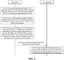
- FIG. 6 is a flowchart of a method for data transmission according to an exemplary embodiment. As illustrated in FIG. 6 , the interaction subjects are a base station and user equipment, and the method includes the following operations.
- the base station generates at least two RRC signalings, here, each of the at least two RRC signalings indicates a respective one of TCI state groups, and each of the TCI state groups includes multiple TCI states.
- the embodiment of the present disclosure also supports indicating the TCI state set by at least two RRC signalings. Accordingly, each of the at least two panels for transmitting the multiple TBs corresponds to a respective one of the TCI state groups. Illustratively, the multiple TBs may be transmitted by the PDSCH.
- the at least two panels are different panels from the same TRP or panels from different TRPs, to enable the base station to transmit data through multiple beam directions.
- the base station transmits the TBs through different panels, and the user equipment also needs to receive the TBs through different receiving beams, so each of the at least two panels corresponds to a respective one of the TCI state groups.
- each RRC signaling includes a TCI state group.
- the TCI state group may be as follows.
- a TCI state group 1 included in a RRC signaling :
- the first TCI state group includes X TCI states and corresponds to one panel
- the second TCI state group includes Y TCI states and corresponds to the other panel.
- one TCI state group includes 64 TCI states (i.e., TCI#0 to TCI#63) and corresponds to one panel
- the other TCI state group also includes 64 TCI states (i.e., TCI#0 to TCI#63) and corresponds to the other panel.
- the two independent TCI state groups may be transmitted to the user equipment at different times through different RRC signalings, or may be simultaneously transmitted to the user equipment through the same RRC signaling.
- the base station generates at least two MAC signalings, here, each of the MAC signalings is used for indicating activation of N TCI states in a respective one of the TCI state groups.
- the embodiment of the present disclosure also indicates the activation of the TCI states through at least two MAC signalings.
- N is a positive integer, for example, the value of N is 8.
- the embodiment of the present disclosure does not specifically limit this.
- the value of N may also be different for different panels. It should be noted that the values of N and M may be the same or different, and the embodiment of the present disclosure is not specifically limited thereto.
- two MAC signalings are needed for the case of transmission through two transmitting beams, one MAC signaling is used for indicating the activation of 8 TCI states in one of the TCI state groups, which need to occupy the X bits; and the other MAC signaling is used for indicating the activation of 8 TCI states in the other of the TCI state groups, which need to occupy the Y bits.
- each of the two MAC CEs is also required to indicate a serving cell ID, a BWP ID, a TRP ID, and the like, and the embodiment of the present disclosure is not specifically limited thereto.
- TCI states activated by indication of each MAC signaling need to be from the respective one of the TCI state groups.
- the two MAC signalings can be transmitted to the user equipment at different times, or may be combined into one MAC signaling and transmitted to the user equipment at the same time.
- the base station generates a first DCI signaling including at least two TCI fields, here, multiple TBs transmitted by at least two panels correspond to the at least two TCI fields, one of the TCI fields is used for indicating TCI states of one or at least two TBs among the multiple TBs, and the first DCI signaling is used for indicating one TCI state in every N TCI states.
- the operation in 603 is similar to the operation in 403 described above, and will not be repeated here.
- the base station transmits the first DCI signaling to the user equipment.
- the user equipment determines a respective receiving beam for receiving each of the multiple TBs according to the first DCI signaling, and receives the TB through the determined respective receiving beam.
- two panels such as panel#1 and panel#2 are used to transmit multiple TBs.
- the user equipment can obtain, according to the DCI-MAC-RRC signalings, an accurate TCI state of each TB transmitted by the respective panels, thereby obtaining accurate receiving beams.
- the base station generates a second DCI signaling including one TCI field, here, multiple TBs transmitted by at least two panels correspond to the one TCI field, and a part of bits in the one TCI field are used for indicating TCI states of one or at least two TBs among the multiple TBs, and the second DCI signaling is used for indicating one TCI state in every N TCI states.
- the operation in 606 is similar to the operation in 406 described above, and will not be repeated here.
- the base station transmits the second DCI signaling to the user equipment.
- the user equipment determines a respective receiving beam for receiving each of the multiple TBs according to the second DCI signaling, and receives the TB through the determined respective receiving beam.
- two panels such as panel#1 and panel#2 are used to transmit multiple TBs.
- the user equipment enables to obtain, according to the DCI-MAC-RRC signalings, an accurate TCI state of each TB transmitted by the respective panels, thereby obtaining accurate receiving beams.
- a base station transmits a signaling indicating at least two receiving beams to user equipment during data transmission, here, the signaling includes TCI states of multiple TBs, the multiple TBs are transmitted by at least two panels, the at least two panels are different panels from the same TRP or panels from different TRPs, and the multiple TBs correspond to the at least two receiving beams of the user equipment, so that the user equipment, after receiving the signaling, determines a respective receiving beam for receiving each of the multiple TBs according to the signaling, and receives the TB through the determined respective receiving beam.
- the signaling includes TCI states of multiple TBs
- the multiple TBs are transmitted by at least two panels
- the at least two panels are different panels from the same TRP or panels from different TRPs
- the multiple TBs correspond to the at least two receiving beams of the user equipment, so that the user equipment, after receiving the signaling, determines a respective receiving beam for receiving each of the multiple TBs according to the signaling, and receives the TB through the
- the embodiment of the present disclosure designs new signaling that enables the user equipment to use the multiple receiving beams for data reception when the base station transmits the data through the multiple transmitting beam directions.
- Such a method for data transmission can be suitable for data transmission based on the multiple TRPs or the multiple panels, and make it possible to perform data transmission between the base station and the user equipment through multiple beams.
- the embodiments of the present disclosure make it possible to perform data transmission between the base station and the user equipment through multiple beams.
- the method for data transmission is capable of supporting data transmission based on multiple TRPs or multiple panels, which is suitable for future evolutions, and improves communication robustness.
- the embodiments of the present disclosure implement the following. 1.
- the base station is capable of scheduling transmission of multiple TBs through one DCI signaling, and the multiple TBs are capable of being transmitted by at least two panels, that is, the multiple TBs can correspond to at least two TCI states, rather than the multiple TBs corresponding to one TCI state.
- One DCI signaling may jointly indicate TCI states of multiple TBs through one TCI field. 3.
- One DCI signaling may independently indicate TCI states of multiple TBs through at least two TCI fields, respectively.
- Multiple TBs can be transmitted by at least two panels, and the at least two panels are different panels from the same TRP or panels from different TRPs, so as to implement multiple beam transmission.
- FIG. 8 is a block diagram of an apparatus for data transmission according to an exemplary embodiment.
- the apparatus includes a first generation module 801 and a transmitting module 802.
- the first generation module 801 is configured to generate a signaling indicating at least two receiving beams of user equipment, here, the signaling includes TCI states of multiple TBs, the multiple TBs are transmitted by at least two panels, the at least two panels are different panels from the same TRP or panels from different TRPs, and the multiple TBs correspond to the at least two receiving beams of the user equipment.
- the transmitting module 802 is configured to transmit the signaling to the user equipment, such that the user equipment determines a respective receiving beam for receiving each of the multiple TBs according to the signaling, and receives the TB through the determined respective receiving beam.
- the apparatus provided in the embodiment of the present disclosure transmits a signaling indicating at least two receiving beams to user equipment during data transmission, herein, the signaling includes TCI states of multiple TBs, the multiple TBs are transmitted by at least two panels, the at least two panels are different panels from the same TRP or panels from different TRPs, and the multiple TBs correspond to the at least two receiving beams of the user equipment, so that the user equipment, after receiving the signaling, determines a respective receiving beam for receiving each of the multiple TBs according to the signaling, and receives the TB through the determined respective receiving beam.
- the embodiment of the present disclosure designs new signaling that enables the user equipment to use the multiple receiving beams for data reception when the base station transmits the data through the multiple transmitting beam directions.
- the method for data transmission can be suitable for data transmission based on the multiple TRPs or the multiple panels, and make it possible to perform data transmission between the base station and the user equipment through multiple beams.
- the apparatus further includes a second generation module 803 and a third generation module 804.
- the second generation module 803 is configured to generate a RRC signaling indicating a TCI state group, here, multiple TCI states included in the TCI state group are divided into at least two TCI state subgroups, and each of the at least two panels corresponds to a respective one of the TCI state subgroups.
- the third generation module 804 is configured to generate a MAC signaling indicating activation of M TCI states in each of the TCI state subgroups.
- the first generation module 801 is further configured to generate a first DCI signaling including at least two TCI fields.
- the multiple TBs correspond to the at least two TCI fields, and one of the TCI fields is used for indicating TCI states of one or at least two TBs among the multiple TBs.
- the first DCI signaling is used for indicating one TCI state in every M TCI states.
- the first generation module 801 is further configured to generate a second DCI signaling including one TCI field.
- the multiple TBs correspond to the one TCI field, and a part of bits in the one TCI field are used for indicating TCI states of one or at least two TBs among the multiple TBs.
- the second DCI signaling is used for indicating one TCI state in every M TCI states.
- the second generation module 803 is configured to generate at least two RRC signalings, herein, each of the at least two RRC signalings indicates a respective one of TCI state groups, each TCI state group includes multiple TCI states, each of the at least two panels corresponds to a respective one of the TCI state groups.
- the third generation module 804 is configured to generate at least two MAC signalings, herein, each of the MAC signalings is used for indicating activation of N TCI states in a respective one of the TCI state groups.
- the first generation module 801 is further configured to generate a first DCI signaling including at least two TCI fields.
- the multiple TBs correspond to the at least two TCI fields, and one of the TCI fields is used for indicating TCI states of one or at least two TBs among the multiple TBs.
- the first DCI signaling is used for indicating one TCI state in every N TCI states.
- the first generation module 801 is further configured to generate a second DCI signaling including one TCI field.
- the multiple TBs correspond to the one TCI field, and a part of bits in the one TCI field are used for indicating TCI states of one or at least two TBs among the multiple TBs.
- the second DCI signaling is used for indicating one TCI state in every N TCI states.
- FIG. 10 is a block diagram of an apparatus for data transmission according to an exemplary embodiment.
- the apparatus includes a first receiving module 1001 and a second receiving module 1002.
- the first receiving module 1001 is configured to receive, from a base station, a signaling indicating at least two receiving beams of user equipment, herein, the signaling includes TCI states of multiple TBs, the multiple TBs are transmitted by at least two panels, the at least two panels are different panels from the same TRP or panels from different TRPs, and the multiple TBs correspond to the at least two receiving beams of the user equipment.
- the second receiving module 1002 is configured to determine a respective receiving beam for receiving each of the multiple TBs according to the signaling and to receive the TB through the determined respective receiving beam.
- the apparatus provided in the embodiment of the present disclosure transmits a signaling indicating at least two receiving beams to user equipment during data transmission
- the signaling includes TCI states of multiple TBs
- the multiple TBs are transmitted by at least two panels, the at least two panels are different panels from the same TRP or panels from different TRPs, and the multiple TBs correspond to the at least two receiving beams of the user equipment, so that the user equipment, after receiving the signaling, determines a respective receiving beam for receiving each of the multiple TBs according to the signaling, and receives the TB through the determined respective receiving beam.
- the embodiment of the present disclosure designs new signaling that enables the user equipment to use the multiple receiving beams for data reception when the base station transmits data through the multiple transmitting beam directions.
- the method for data transmission can be suitable for data transmission based on the multiple TRPs or the multiple panels, and make it possible to perform data transmission between the base station and the user equipment through multiple beams.
- FIG. 11 is a block diagram of user equipment according to an exemplary embodiment.
- the user equipment 1100 may be a mobile phone, a computer, a digital broadcast terminal, a messaging device, a game console, a tablet device, a medical device, a fitness device, a personal digital assistant, or the like.
- the user equipment 1100 may include one or more of following components: a processing component 1102, a memory 1104, a power component 1106, a multimedia component 1108, an audio component 1110, an Input/Output (I/O) interface 1112, a sensor component 1114, and a communication component 1116.
- a processing component 1102 a memory 1104, a power component 1106, a multimedia component 1108, an audio component 1110, an Input/Output (I/O) interface 1112, a sensor component 1114, and a communication component 1116.
- the processing component 1102 typically controls the overall operations of apparatus 1100, such as operations associated with display, telephone calls, data communications, camera operations, and recording operations.
- the processing component 1102 may include one or more processors 1120 to execute instructions to perform all or part of the operations in the abovementioned methods.
- the processing component 1102 may include one or more modules which facilitate interaction between the processing component 1102 and other components.
- the processing component 1102 may include a multimedia module to facilitate interaction between the multimedia component 1108 and the processing component 1102.
- the memory 1104 is configured to store various types of data to support operation of the user equipment 1100. Examples of such data include instructions for any application or method operating on the user equipment 1100, contact data, phone book data, messages, pictures, video, etc.
- the memory 1104 may be implemented by any type of volatile or non-volatile storage device, or a combination thereof, such as a Static Random Access Memory (SRAM), an Electrically Erasable Programmable Read-Only Memory (EEPROM), an Erasable Programmable Read-Only Memory (EPROM), a Programmable Read-Only Memory (PROM), a Read-Only Memory (ROM), a magnetic memory, a flash memory, and a magnetic or optical disk.
- SRAM Static Random Access Memory
- EEPROM Electrically Erasable Programmable Read-Only Memory
- EPROM Erasable Programmable Read-Only Memory
- PROM Programmable Read-Only Memory
- ROM Read-Only Memory
- magnetic memory a magnetic memory
- flash memory and a magnetic or optical disk
- the power component 1106 provides power for various components of the user equipment 1100.
- the power component 1106 may include a power management system, one or more power supplies, and other components associated with generation, management, and distribution of the power for the user equipment 1100.
- the multimedia component 1108 includes a screen providing an output interface between the user equipment 1100 and a user.
- the screen may include Liquid Crystal Display (LCD) and a Touch Panel (TP). If the screen includes the TP, the screen may be implemented as a touch screen to receive an input signal from the user.
- the TP includes one or more touch sensors to sense touches, swipes, and gestures on the TP. The touch sensors may not only sense a boundary of a touch or swipe action, but also detect a duration and pressure associated with the touch or swipe action.
- the multimedia component 1108 includes a front camera and/or a rear camera.
- the front camera and/or the rear camera may receive external multimedia data when the user equipment 1100 is in an operating mode, such as a photographing mode or a video mode.
- an operating mode such as a photographing mode or a video mode.
- Each of the front camera and the rear camera may be a fixed optical lens system or have focusing and optical zooming capabilities.
- the audio component 1110 is configured to output and/or input audio signals.
- the audio component 1110 includes a Microphone (MIC), and the MIC is configured to receive an external audio signal when the user equipment 1100 is in the operation mode, such as a call mode, a recording mode and a voice recognition mode.
- the received audio signal may further be stored in the memory 1104 or sent through the communication component 1116.
- the audio component 1110 further includes a speaker configured to output the audio signal.
- the I/O interface 1112 provides an interface between the processing component 1102 and a peripheral interface module, and the peripheral interface module may be a keyboard, a click wheel, a button and the like.
- the button may include, but not limited to, a home button, a volume button, a starting button, and a locking button.
- the sensor component 1114 includes one or more sensors configured to provide status assessment in various aspects for the user equipment 1100. For instance, the sensor component 1114 may detect the on/off state of the user equipment 1100, relative positioning of components, such as a display and a small keyboard of the user equipment 1100. The sensor component 1114 may further detect a change in a position of the user equipment 1100 or a component of the user equipment 1100, presence or absence of contact between user and the user equipment 1100, orientation or acceleration/deceleration of the user equipment 1100, and a change in the temperature of the user equipment 1100. The sensor component 1114 may include a proximity sensor configured to detect presence of an object nearby without any physical contact.
- the sensor component 1114 may also include a photosensor, such as a Complementary Metal Oxide Semiconductor (CMOS) or Charge Coupled Device (CCD) image sensor, configured for use in an imaging application.
- CMOS Complementary Metal Oxide Semiconductor
- CCD Charge Coupled Device
- the sensor component 1114 may also include an acceleration sensor, a gyroscope sensor, a magnetic sensor, a pressure sensor, or a temperature sensor.
- Communication component 1116 is configured to facilitate wired or wireless communication between the user equipment 1100 and other device.
- the user equipment 1100 may access a communication-standard-based wireless network, such as a Wi-Fi network, a 2nd-Generation (2G) or 3rd-Generation (3G) network or a combination thereof.
- the communication component 1116 receives broadcast signal or broadcast associated information from an external broadcast management system through a broadcast channel.
- the communication component 1116 further includes a Near Field Communication (NFC) module to facilitate short-range communication.
- NFC Near Field Communication
- the user equipment 1100 may be implemented by one or more Application Specific Integrated Circuits (ASICs), Digital Signal Processors (DSPs), Digital Signal Processing Devices (DSPDs), Programmable Logic Devices (PLDs), Field Programmable Gate Arrays (FPGAs), controllers, micro-controllers, microprocessors or other electronic components, and is configured to perform the abovementioned methods.
- ASICs Application Specific Integrated Circuits
- DSPs Digital Signal Processors
- DSPDs Digital Signal Processing Devices
- PLDs Programmable Logic Devices
- FPGAs Field Programmable Gate Arrays
- controllers micro-controllers, microprocessors or other electronic components, and is configured to perform the abovementioned methods.
- a non-transitory computer-readable storage medium including an instruction such as the memory 1104 including an instruction
- the instruction may be executed by the processor 1120 of the user equipment 1100 to implement the abovementioned methods.
- the non-transitory computer-readable storage medium may be a ROM, a Random Access Memory (RAM), a Compact Disc Read-Only Memory (CD-ROM), a magnetic tape, a floppy disc, an optical data storage device and the like.
- Non-transitory computer-readable storage medium having stored thereon instructions that, when executed by a processor of user equipment, cause the user equipment to perform the abovementioned methods for data transmission.
- FIG. 12 is a block diagram of a base station according to an exemplary embodiment.
- the base station includes a processor 1201, a memory 1202 for storing instructions executable by the processor, and a transceiver 1203.
- the processor 1201 is configured to execute the following instructions.
- a signaling indicating at least two receiving beams of user equipment is generated, herein, the signaling includes TCI states of multiple TBs, the multiple TBs are transmitted by at least two panels, the at least two panels are different panels from the same TRP or panels from different TRPs, and the multiple TBs correspond to the at least two receiving beams of the user equipment.
- the signaling is transmitted to the user equipment, such that the user equipment determines, according to the signaling, a respective receiving beam for receiving each of the multiple TBs and receives the TB through the determined respective receiving beam.
- a computer-readable storage medium having stored thereon instructions that, executed by a processor of a base station, cause the base station to perform the abovementioned methods for data transmission.
Landscapes
- Engineering & Computer Science (AREA)
- Signal Processing (AREA)
- Computer Networks & Wireless Communication (AREA)
- Mobile Radio Communication Systems (AREA)
Abstract
Description
- The present disclosure relates to the field of communication technologies, and more particularly, to a method for data transmission, a base station, user equipment, and a storage medium.
- In New Radio (NR), in a cast that the communication band is located in Frequency Range (FR) 2, since the path loss of the high frequency communication is relatively large, data transmission based on beam(s) is generally required in order to ensure coverage and resist the path loss. The FR2 refers to a high frequency band greater than 6 GHz. For example, for a beam-based reception process, the base station indicates the Transmission Configuration Indication (TCI) states corresponding to the type D through signaling, so as to inform the user equipment of the receiving beam to be used when receiving. Each TCI state corresponds to a Reference Signal (RS) identifier, and the RS may be either a non-zero power Channel State Information Reference Signal (CSI-RS) or a Synchronization Signal Block (SSB).
- In the related art, the base station indicates only one beam direction through signaling. For example, for a reception process of Physical Downlink Shared Channel (PDSCH), different Transport Blocks (TBs) are transmitted by the same panel of the same Transmission Reception Point (TRP), so that the TCI states used by the different TBs are the same. That is, the base station notifies the user equipment to receive these TBs through the same receiving beam.
- However, future Multiple-Input Multiple-Output (MIMO) needs to support data transmission based on multiple TRPs or multiple panels. That is, the base station needs to use multiple transmitting beam directions for data transmission, and correspondingly, the user equipment needs to use multiple receiving beams for data reception. Therefore, the signaling for indicating one receiving beam direction in the related art will no longer be suitable for future evolutions. To this end, in the case that such as different TBs are transmitted by different TRPs or different panels, how to design new signaling to enable data transmission between the base station and the user equipment through multiple beams has become an urgent problem to be solved by a person skilled in the art.
- The present disclosure provides a method for data transmission, a base station, user equipment, and a storage medium, which enable data transmission between the base station and the user equipment through multiple beams.
- According to a first aspect of an embodiment of the present disclosure, there is provided a method for data transmission applied to a base station. The method includes the following operations.
- The base station generates a signaling indicating at least two receiving beams of user equipment. Herein, the signaling includes TCI states of multiple TBs, the multiple TBs are transmitted by at least two panels, the at least two panels are different panels from the same TRP or panels from different TRPs, and the multiple TBs correspond to the at least two receiving beams of the user equipment.
- The base station transmits the signaling to the user equipment, such that the user equipment determines a respective receiving beam for receiving each of the multiple TBs according to the signaling and receives the TB through the determined respective receiving beam.
- In a possible implementation, the method further includes the following operations.
- The base station generates a Radio Resource Control (RRC) signaling. Herein, the RRC signaling indicates a TCI state group, multiple TCI states included in the TCI state group are divided into at least two TCI state subgroups, and each of the at least two panels corresponds to a respective one of the at least two TCI state subgroups.
- The base station generates a Media Access Control (MAC) signaling. Herein, the MAC signaling indicates activation of M TCI states in each of the TCI state subgroups.
- In a possible implementation, the operation that the base station generates a signaling indicating at least two receiving beams of user equipment includes the following operations.
- The base station generates a first Downlink Control Information (DCI) signaling that includes at least two TCI fields.
- Herein, the multiple TBs correspond to the at least two TCI fields, and one of the TCI fields indicates TCI states of one or at least two TBs among the multiple TBs.
- Herein, the first DCI signaling indicates one TCI state in every M TCI states.
- In a possible implementation, the operation that the base station generates a signaling indicating at least two receiving beams of user equipment includes the following operations.
- The base station generates a second DCI signaling that includes one TCI field.
- Herein, the multiple TBs correspond to the one TCI field, and a part of bits in the one TCI field indicate TCI states of one or at least two TBs among the multiple TBs.
- Herein, the second DCI signaling indicates one TCI state in every M TCI states.
- In a possible implementation, the method further includes the following operations.
- The base station generates at least two RRC signalings. Herein, each of the at least two RRC signalings indicates a respective one of TCI state groups, each of the TCI state groups includes multiple TCI states, each of the at least two panels corresponds to a respective one of the TCI state groups.
- The base station generates at least two MAC signalings. Herein, each of the at least two MAC signalings indicates activation of N TCI states in a respective one of the TCI state groups.
- In a possible implementation, the operation that the base station generates a signaling indicating at least two receiving beams of user equipment includes the following operations.
- The base station generates a first DCI signaling that includes at least two TCI fields.
- Herein, the multiple TBs correspond to the at least two TCI fields, and one of the TCI fields indicates TCI states of one or at least two TBs among the multiple TBs.
- Herein, the first DCI signaling indicates one TCI state in every N TCI states.
- In a possible implementation, the operation that the base station generates a signaling indicating at least two receiving beams of user equipment includes the following operations.
- The base station generates a second DCI signaling that includes one TCI field.
- Herein, the multiple TBs correspond to the one TCI field, and a part of bits in the one TCI field indicate TCI states of one or at least two TBs among the multiple TBs.
- Herein, the second DCI signaling indicates one TCI state in every N TCI states.
- According to a second aspect of an embodiment of the present disclosure, there is provided a method for data transmission applied to user equipment. The method includes the following operations.
- The user equipment receives, from a base station, a signaling indicating at least two receiving beams of the user equipment. Herein, the signaling includes TCI states of multiple TBs, the multiple TBs are transmitted by at least two panels, the at least two panels are different panels from the same TRP or panels from different TRPs, and the multiple TBs correspond to the at least two receiving beams of the user equipment.
- The user equipment determines a respective receiving beam for receiving each of the multiple TBs according to the signaling, and receives the TB through the determined respective receiving beam.
- According to a third aspect of an embodiment of the present disclosure, there is provided an apparatus for data transmission, for use in a base station. The apparatus includes a first generation module and a transmitting module.
- The first generation module is configured to generate a signaling indicating at least two receiving beams of user equipment, here, the signaling includes TCI states of multiple TBs, the multiple TBs are transmitted by at least two panels, the at least two panels are different panels from the same TRP or panels from different TRPs, and the multiple TBs correspond to the at least two receiving beams of the user equipment.
- The transmitting module is configured to transmit the signaling to the user equipment, such that the user equipment determines a respective receiving beam for receiving each of the multiple TBs according to the signaling and receives the TB through the determined respective receiving beam.
- In a possible implementation, the apparatus further includes a second generation module and a third generation module.
- The second generation module is configured to generate a RRC signaling, herein, the RRC signaling indicates a TCI state group, multiple TCI states included in the TCI state group are divided into at least two TCI state subgroups, and each of the at least two panels correspond to a respective one of the at least two TCI state subgroups.
- The third generation module is configured to generate a MAC signaling, here, the MAC signaling indicates activation of M TCI states in each of the TCI state subgroups.
- In a possible implementation, the first generation module is further configured to generate a first DCI signaling that includes at least two TCI fields.
- Herein, the multiple TBs correspond to the at least two TCI fields, and one of the TCI fields indicates TCI states of one or at least two TBs among the multiple TBs.
- Herein, the first DCI signaling indicates one TCI state in every M TCI states.
- In a possible implementation, the first generation module is further configured to generate a second DCI signaling that includes one TCI field.
- Herein, the multiple TBs correspond to the one TCI field, and a part of bits in the one TCI field indicate TCI states of one or at least two TBs among the multiple TBs.
- Herein, the second DCI signaling indicates one TCI state in every M TCI states.
- In a possible implementation, the apparatus further includes a second generation module and a third generation module.
- The second generation module is configured to generate at least two RRC signalings, here, each of the at least two RRC signalings indicates a respective one of TCI state groups, each of the TCI state groups includes multiple TCI states, and each of the at least two panels correspond to a respective one of the TCI state groups.
- The third generation module is configured to generate at least two MAC signalings, here, each of the MAC signalings indicates activation of N TCI states in a respective one of the TCI state groups.
- In a possible implementation, the first generation module is further configured to generate a first DCI signaling that includes at least two TCI fields.
- Herein, the multiple TBs correspond to the at least two TCI fields, and one of the TCI fields indicates TCI states of one or at least two TBs among the multiple TBs.
- Herein, the first DCI signaling indicates one TCI state in every N TCI states.
- In a possible implementation, the first generation module is further configured to generate a second DCI signaling that includes one TCI field.
- Herein, the multiple TBs correspond to the one TCI field, and a part of bits in the one TCI field indicate TCI states of one or at least two TBs among the multiple TBs.
- Herein, the second DCI signaling indicates one TCI state in every N TCI states.
- According to a fourth aspect of an embodiment of the present disclosure, there is provided an apparatus for data transmission, for use in user equipment. The apparatus includes a first receiving module and a second receiving module.
- The first receiving module is configured to receive, from a base station, a signaling indicating at least two receiving beams of the user equipment, here, the signaling includes TCI states of multiple TBs, the multiple TBs are transmitted by at least two panels, the at least two panels are different panels from the same TRP or panels from different TRPs, and the multiple TBs correspond to the at least two receiving beams of the user equipment.
- The second receiving module is configured to determine a respective receiving beam for receiving each of the multiple TBs according to the signaling and receive the TB through the determined respective receiving beam.
- According to a fifth aspect of the embodiments of the present disclosure, there is provided a base station. The base station includes a processor and a memory for storing instructions executable by the processor.
- Herein, the processor is configured to: generate a signaling indicating at least two receiving beams of user equipment, here, the signaling includes TCI states of multiple TBs, the multiple TBs are transmitted by at least two panels, the at least two panels are different panels from the same TRP or panels from different TRPs, and the multiple TBs correspond to the at least two receiving beams of the user equipment; and transmit the signaling to the user equipment, such that the user equipment determines a respective receiving beam for receiving each of the multiple TBs according to the signaling and receives the TB through the determined respective receiving beam.
- According to a sixth aspect of an embodiment of the present disclosure, there is provided user equipment. The user equipment includes a processor and a memory for storing instructions executable by the processor.
- Herein, the processor is configured to: receive, from a base station, a signaling indicating at least two receiving beams of the user equipment, here, the signaling includes TCI states of multiple TBs, the multiple TBs are transmitted by at least two panels, the at least two panels are different panels from the same TRP or panels from different TRPs, and the multiple TBs correspond to the at least two receiving beams of the user equipment; and determine a respective receiving beam for receiving each of the multiple TBs according to the signaling, and receive the TB through the determined respective receiving beam.
- According to a seventh aspect of an embodiment of the present disclosure, there is provided a computer-readable storage medium having stored thereon at least one instruction, the at least one instruction is loaded and executed by a processor to perform the operations in the method for data transmission according to the above first aspect.
- According to an eighth aspect of an embodiment of the present disclosure, there is provided a computer-readable storage medium having stored thereon at least one instruction, the at least one instruction is loaded and executed by a processor to perform operations in the method for data transmission according to the above second aspect.
- The technical solution provided by the embodiments of the present disclosure includes the following advantages.
- During the data transmission, a base station in the embodiments of the present disclosure transmits to user equipment a signaling indicating at least two receiving beams, here, the signaling includes TCI states of multiple TBs, the multiple TBs are transmitted by at least two panels, the at least two panels are different panels from the same TRP or panels from different TRPs, and the multiple TBs correspond to the at least two receiving beams of the user equipment, so that the user equipment, after receiving the signaling, determines a respective receiving beam for receiving each of the multiple TBs according to the signaling, and receives the TB through the determined respective receiving beam. The embodiments of the present disclosure design new signaling that enables the user equipment to use the multiple receiving beams for data reception when the base station transmits the data through the multiple transmitting beams. Such a method for data transmission can be suitable for data transmission based on the multiple TRPs or the multiple panels, and make it possible to perform data transmission between the base station and the user equipment through multiple beams.
- It should be understood that the foregoing general description and the following detailed description are merely exemplary and not intended to limit the present disclosure.
- The accompanying drawings, which are incorporated in and constitute a part of this specification, illustrate embodiments consistent with the present disclosure and, together with the description, serve to explain the principles of the present disclosure.
-
FIG. 1 is a diagram of an implementation environment involved in a method for data transmission according to an exemplary embodiment. -
FIG. 2 is a flowchart of a method for data transmission according to an exemplary embodiment. -
FIG. 3 is a flowchart of a method for data transmission according to an exemplary embodiment. -
FIG. 4 is a flowchart of a method for data transmission according to an exemplary embodiment. -
FIG. 5 is a flowchart of a method for data transmission according to an exemplary embodiment. -
FIG. 6 is a flowchart of a method for data transmission according to an exemplary embodiment. -
FIG. 7 is a flowchart of a method for data transmission according to an exemplary embodiment. -
FIG. 8 is a block diagram of an apparatus for data transmission according to an exemplary embodiment. -
FIG. 9 is a block diagram of an apparatus for data transmission according to an exemplary embodiment. -
FIG. 10 is a block diagram of an apparatus for data transmission according to an exemplary embodiment. -
FIG. 11 is a block diagram of user equipment according to an exemplary embodiment. -
FIG. 12 is a block diagram of a base station according to an exemplary embodiment. - Reference will now be made in detail to exemplary embodiments, examples of which are illustrated in the accompanying drawings. The following description refers to the accompanying drawings in which the same numbers in different drawings represent the same or similar elements unless otherwise represented. The implementations set forth in the following description of exemplary embodiments do not represent all implementations consistent with the present disclosure. Instead, they are merely examples of apparatuses and methods consistent with the aspects of the present disclosure as recited in the appended claims.
-
FIG. 1 is a diagram of an implementation environment involved in a method for data transmission according to an exemplary embodiment. As illustrated inFIG. 1 , the implementation environment includes abase station 101 anduser equipment 102, and thebase station 101 and theuser equipment 102 are connected through a communication network. - For the beam-based reception process, the TCI state is used for notifying the
user equipment 102 of a receiving beam to be used when receiving the Physical Downlink Control Channel (PDCCH)/PDSCH, and the receiving beam is the same as a receiving beam for receiving a certain SSB or a certain CSI-RS transmitted by the base station. Herein, thebase station 101 indicates, through the TCI field in the DCI signaling, the receiving beam to be used when theuser equipment 102 receives the TB transmitted in the PDSCH. In the related art, thebase station 101 indicates only one receiving beam direction through DCI signaling. Illustratively, for two TBs of one PDSCH, the TCI states corresponding to the two TBs are consistent since the two TBs are transmitted by the same panel of the same TRP. For example, taking the two TBs as TB1 and TB2 respectively, the corresponding DCI signaling can be as follows. -
- Modulation and coding scheme-5 bits
- New data indicator-1 bit
- Redundancy version-2 bits
-
- Modulation and coding scheme-5 bits
- New data indicator-1 bit
- Redundancy version-2 bits
... .... - Transmission configuration indication - 0 bit if higher layer parameter tci-PresentInDCI is not enabled; otherwise 3 bits.
- As can be seen from the above DCI signaling, TB1 and TB2 correspond to the same TCI state. That is, the
base station 101 notifies theuser equipment 102 to receive the two TBs through the same receiving beam. Further, in order to clarify how thebase station 101 indicates one receiving beam of theuser equipment 102, an example of a reception process of PDSCH is described below.
1. Thebase station 101 generates a RRC signaling, and indicates multiple TCI states through the RRC signaling.
Herein, the number of the multiple TCI states may be up to 64 or up to 128, which is not specifically limited in the embodiment of the present disclosure.
2. Thebase station 101 generates a MAC signaling, and indicates activation of a part of the TCI states in the RRC signaling through the MAC signaling.
Herein, the number of the part of the TCI states may be 8, and this embodiment of the present disclosure is not specifically limited thereto. In a possible implementation, when the number of TCI states included in the RRC signaling is less than 8, thebase station 101 may not need to generate the MAC signaling.
3. Thebase station 101 generates a DCI signaling, and indicates, through the DCI signaling, one of multiple TCI states activated by the MAC signaling, for use by theuser equipment 102 to receive the PDSCH. That is, thebase station 101 notifies theuser equipment 102 to use one receiving beam to receive all TBs included in the PDSCH.
4. Thebase station 101 transmits the DCI signaling to theuser equipment 102, and the DCI signaling indicates the receiving beam, which used in receiving the RS corresponding to the RS identifier included in the TCI state, used by theuser equipment 102 to receive the PDSCH. The details are shown in the Table 1 below.Table 1 TCI state RS index Remarks TCI#0 SSB index#1 If the base station notifies UE to use the TCI#0, this means that the base station notifies the UE to use the receiving beam used in receiving the SSB index#1 to receive the PDSCH. TCI#1 SSB index#2 TCI#2 CSI-RS index#5 TCI#3 CSI-RS index#6 ... ... ... ... - The above description is directed to a single receiving beam direction. However, future MIMO needs to support data transmission based on multiple TRPs or multiple panels. That is to say, the
base station 101 needs to use multiple transmitting beams for data transmission, and correspondingly, theuser equipment 102 needs to use multiple receiving beams for data reception. Therefore, it becomes a problem to be solved in the embodiments of the present disclosure that how to indicate the TCI states. In the following, the data transmission between thebase station 101 and theuser equipment 102 through multiple beams is explained in detail based on the following embodiments. -
FIG. 2 is a flowchart of a method for data transmission according to an exemplary embodiment. As illustrated inFIG. 2 , the method is applied to a base station, and includes the following operations. - In 201, the base station generates a signaling indicating at least two receiving beams of user equipment, here, the signaling includes TCI states of multiple TBs, the multiple TBs are transmitted by at least two panels, the at least two panels are different panels from the same TRP or panels from different TRPs, and the multiple TBs correspond to the at least two receiving beams of the user equipment.
- In 202, the base station transmits the signaling to the user equipment, such that the user equipment determines a respective receiving beam for receiving each of the multiple TBs according to the signaling and receives the TB through the determined respective receiving beam.
- According to the method provided in the embodiment of the present disclosure, a base station transmits a signaling indicating at least two receiving beams to user equipment during data transmission, here, the signaling includes TCI states of multiple TBs, the multiple TBs are transmitted by at least two panels, the at least two panels are different panels from the same TRP or panels from different TRPs, and the multiple TBs correspond to the at least two receiving beams of the user equipment. In such a manner, the user equipment, after receiving the signaling, determines a respective receiving beam for receiving each of the multiple TBs according to the signaling, and receives the TB through the determined respective receiving beam. The embodiment of the present disclosure designs new signaling that enables the user equipment to use the multiple receiving beams for data reception when the base station transmits data through the multiple transmitting beam directions. Such a method for data transmission can be suitable for data transmission based on the multiple TRPs or the multiple panels, and make it possible to perform data transmission between the base station and the user equipment through multiple beams.
- In a possible implementation, the method further includes the following operations.
- The base station generates a RRC signaling indicating a TCI state group, here, multiple TCI states included in the TCI state group are divided into at least two TCI state subgroups, and each of the at least two panels corresponds to a respective one of the TCI state subgroups.
- The base station generates a MAC signaling indicating activation of M TCI states in each of the TCI state subgroups.
- In a possible implementation, the operation that the base station generates a signaling indicating at least two receiving beams of user equipment includes the following operations.
- The base station generates a first DCI signaling including at least two TCI fields.
- Herein, the multiple TBs correspond to the at least two TCI fields, and one of the TCI fields is used for indicating TCI states of one or at least two TBs among the multiple TBs.
- Herein, the first DCI signaling is used for indicating one TCI state in every M TCI states.
- In a possible implementation, the operation that the base station generates a signaling indicating at least two receiving beams of user equipment includes the following operations.
- The base station generates a second DCI signaling including one TCI field.
- Herein, the multiple TBs correspond to the one TCI field, and a part of bits in the one TCI field are used for indicating TCI states of one or at least two TBs among the multiple TBs.
- Herein, the second DCI signaling is used for indicating one TCI state in every M TCI states.
- In a possible implementation, the method further includes the following operations.
- The base station generating at least two RRC signalings, here, each of the at least two RRC signalings indicates a respective one of TCI state groups, each of the TCI state groups includes multiple TCI states, and each of the at least two panels corresponds to a respective one of the TCI state groups.
- The base station generates at least two MAC signalings, here, each of the at least two MAC signalings is used for indicating activation of N TCI states in a respective one of the TCI state groups.
- In a possible implementation, the operation that the base station generates a signaling indicating at least two receiving beams of user equipment includes the following operations.
- The base station generates a first DCI signaling including at least two TCI fields.
- Herein, the multiple TBs correspond to the at least two TCI fields, and one of the TCI fields is used for indicating TCI states of one or at least two TBs among the multiple TBs.
- Herein, the first DCI signaling is used for indicating one TCI state in every N TCI states.
- In a possible implementation, the operation that the base station generates a signaling indicating at least two receiving beams of user equipment includes the following operations.
- The base station generates a second DCI signaling including one TCI field.
- Herein, the multiple TBs correspond to the one TCI field, and a part of bits in the one TCI field are used for indicating TCI states of one or at least two TBs among the multiple TBs.
- Herein, the second DCI signaling is used for indicating one TCI state in every N TCI states.
- Any combination of the above alternative solutions may be used for forming alternative embodiments of the present disclosure, and details are not described herein.
-
FIG. 3 is a flowchart of a method for data transmission according to an exemplary embodiment. As illustrated inFIG. 3 , the method is applied to user equipment, and includes the following operations. - In 301, the user equipment receives, from a base station, a signaling for indicating at least two receiving beams of the user equipment, here, the signaling includes TCI states of multiple TBs, the multiple TBs are transmitted by at least two panels, the at least two panels are different panels from the same TRP or panels from different TRPs, and the multiple TBs correspond to the at least two receiving beams of the user equipment.
- In 302, the user equipment determines a respective receiving beam for receiving each of the multiple TBs according to the signaling, and receives the TB through the determined respective receiving beam.
- According to the method provided in the embodiment of the present disclosure, a base station transmits a signaling indicating at least two receiving beams to user equipment during data transmission, here, the signaling includes TCI states of multiple TBs, the multiple TBs are transmitted by at least two panels, the at least two panels are different panels from the same TRP or panels from different TRPs, and the multiple TBs correspond to the at least two receiving beams of the user equipment. In such manner, the user equipment, upon reception of the signaling, determines a respective receiving beam for receiving each of the multiple TBs according to the signaling, and receives the TB through the determined respective receiving beam. The embodiment of the present disclosure designs new signaling that enables the user equipment to use the multiple receiving beams for data reception when the base station transmits data through the multiple transmitting beam directions. Such a method for data transmission can be suitable for data transmission based on the multiple TRPs or the multiple panels, and make it possible to perform data transmission between the base station and the user equipment through multiple beams.
-
FIG. 4 is a flowchart of a method for data transmission according to an exemplary embodiment. As illustrated inFIG. 4 , the interaction subjects are a base station and user equipment, and the method for data transmission includes the following operations. - In 401, the base station generates a RRC signaling indicating a TCI state group, herein, multiple TCI states included in the TCI state group are divided into at least two TCI state subgroups.
- Herein, each of at least two panels for transmitting multiple TBs corresponds to a respective one of the at least two TCI state subgroups. Illustratively, the multiple TBs are transmitted through PDSCH, which is not specifically limited in the embodiment of the present disclosure.
- In an embodiment of the present disclosure, the at least two panels are different panels from the same TRP or panels from different TRPs, to enable the base station to transmit data through multiple beam directions. Illustratively, for example, the number of TBs to be transmitted is 3. In a possible implementation, two of the three TBs are transmitted by one panel and the other of the three TBs is transmitted by the other panel; and these two panels for transmitting the three TBs are either different panels from the same TRP, or panels from two TRPs respectively. Herein, the TBs transmitted by the different panels are received by the user equipment through different receiving beams. Therefore, each of the at least two panels corresponds to a respective one of the TCI state subgroups. In another possible implementation, each of the three TBs can also be transmitted by a different panel; and these three panels for transmitting the three TBs are either different panels from the same TRP, or panels from three TRPs respectively.
- For this operation, all candidate TCI states corresponding to multiple panels are indicated collectively by a single RRC signaling.
- Taking transmitting two TBs as an example. If a RRC signaling indicates 64 TCI states in a case that the base station transmits two TBs through one transmitting beam, the number of TCI states indicated by the RRC signaling may be not less than 64 and not greater than 128 in a case that the base station transmits two TBs through two transmitting beams, so as to form a TCI state group. Herein, in the TCI state group, the first X TCI states correspond to one panel, and form a TCI state subgroup; the next Y TCI states correspond to the other panel, and form the other TCI state subgroup. Correspondingly, the TCI state group may be as follows.
- TCI#0
- TCI#1
- ... ...
- TCI#X-1
- TCI#X
- ... ...
- TCI#X+Y-1
- As described above, the X+Y TCI states included in the TCI state group are divided into two TCI state subgroups, where TCI#0 to TCI#X-1 form one TCI state subgroup, and TCI#X to TCI#X+Y-1 form the other TCI state subgroup. Illustratively, assuming that the values of X and Y are both 64, TCI#0 to TCI#63 form one TCI state subgroup corresponding to one panel; TCI#64 to TCI#127 form the other TCI state subgroup corresponding to the other panel.
- In 402, the base station generates a MAC signaling, herein, the MAC signaling is used for indicating activation of M TCI states in each of the TCI state subgroups.
- For this operation, the activation of the TCI states is indicated collectively by a single MAC signaling.
- Here, the value of M is a positive integer. For example, the value of M may be 8, or the value of M may be different for different TCI state subgroups. For example, the value of M is 8 for the TCI state subgroup #1, and the value of M is 6 for the TCI state subgroup #2, which are not specifically limited in the embodiment of the present disclosure.
- Continuing with the example of transmitting two TBs, if one transmitting beam is used for data transmission for the transmission process of the PDSCH, and the MAC signaling is used for indicating activation of 8 TCI states among the 64 TCI states indicated by the RRC signaling, then for the case of transmission through two transmitting beams, the MAC signaling can indicate to activate 16 TCI states among X+Y TCI states indicated by the RRC signaling, and the 16 TCI states may not be from the same TCI state subgroup. For example, 8 TCI states among the 16 TCI states are from one TCI state subgroup and the remaining 8 TCI states among the 16 TCI states are from the other TCI state subgroup. Accordingly, the MAC signaling for indicating the activation of the TCI states needs to occupy X+Y bits.
- In addition, the MAC CE (Control Element) also needs to indicate a serving cell ID, a BWP (Bandwidth Part) ID, and the like.
- In summary, the TCI states activated by indication of the MAC signaling need to be from the respective TCI state subgroups. Illustratively, in a case that two TRPs transmit multiple TBs, if each TRP has only one panel, all the TCI states activated by indication of the MAC signaling cannot correspond to only one TRP, because the DCI signaling transmitted by the base station to the user equipment needs to indicate at least two beam directions and for this case, one TRP corresponds to only one beam direction at the same time. If two TRPs transmit multiple TBs, and each TRP has at least two panels, then all the TCI states activated by indication of the MAC signaling may correspond to one TRP, and correspond to different panels of the one TRP, so that the subsequent DCI signaling can indicate at least two beam directions, and each of the beam directions corresponds to a respective one of the panels.
- In 403, the base station generates a first DCI signaling including at least two TCI fields, here, the multiple TBs transmitted by the at least two panels correspond to the at least two TCI fields, one of the TCI fields indicates TCI states of one or at least two TBs among the multiple TBs, and the first DCI signaling indicates one TCI state in every M TCI states.
- Herein, the first DCI signaling is also referred to as the signaling indicating at least two receiving beams of the user equipment. As described above, the first DCI signaling includes TCI states of multiple TBs, and all of these TCI states are activated by indication of the MAC signaling.
- In the embodiment of the present disclosure, the number of TCI fields included in the DCI signaling is not less than 2 and not greater than the number of TBs transmitted. Illustratively, assuming that three TBs are transmitted, two of the three TBs are transmitted by one panel and the other of the three TBs is transmitted by the other panel, the two TBs transmitted by the one panel correspond to one TCI field and the other TB corresponds to the other TCI field.
- Taking each of two TBs corresponding to a respective one of two TCI fields as an example, the first DCI signaling may be as follows.
- For transport block 1:
- Modulation and coding scheme-5 bits
- New data indicator-1 bit
- Redundancy version-2 bits
- Transmission configuration indication-0 bit if higher layer parameter tci-PresentInDCI is not enabled; otherwise 3 bits.
- For transport block 2:
- Modulation and coding scheme-5 bits
- New data indicator-1 bit
- Redundancy version-2 bits
- Transmission configuration indication - 0 bit if higher layer parameter tci-PresentInDCI is not enabled; otherwise 3 bits.
- In 404, the base station transmits the first DCI signaling to the user equipment.
- In 405, the user equipment determines a respective receiving beam for receiving each of the multiple TBs according to the first DCI signaling, and receives the TB through the determined respective receiving beam.
- Herein, the DCI signaling received by the user equipment includes TCI states of multiple TBs, and each TCI state includes an RS identifier (also referred to as RS ID or RS index). The user equipment determines a corresponding RS according to the RS identifier in the TCI state, and then receives the corresponding TB through a receiving beam for receiving the corresponding RS.
- In the above process, for example, two panels, such as panel#1 and panel#2, are used to transmit multiple TBs.
- 1. The RRC signaling gives a TCI state subgroup # 1 corresponding to the X candidate TCI states used when the panel#1 transmits the TB(s) and a TCI state subgroup # 2 corresponding to the Y candidate TCI states used when the panel#2 transmits the TB(s).
- 2. The MAC signaling gives the M TCI states activated in the TCI state subgroup # 1 and the M TCI states activated in the TCI state subgroup # 2. Herein, the low X bits in the MAC signaling are used for activating the M TCI states among the X candidate TCI states in the TCI state subgroup # 1, and the high Y bits in the MAC signaling are used for activating the M TCI states among the Y candidate TCI states in the TCI state subgroup # 2.
- 3. The first DCI signaling gives one of the M TCI states activated by the MAC signaling. Herein, the first TCI field in the first DCI signaling is used for indicating one of the M TCI states activated by the low X bits in the MAC signaling, and the second TCI field in the first DCI signaling is used for indicating one of the M TCI states activated by the high Y bits in the MAC signaling.
- Thus, the user equipment can obtain, according to the DCI-MAC-RRC signalings, an accurate TCI state of each TB transmitted by the respective panels, thereby obtaining the accurate receiving beams.
- In a possible implementation, as illustrated in
FIG. 5 , theabove operations 403 to 405 may also be replaced by the following operations 406 to 408. - In 406, the base station generates a second DCI signaling including one TCI field, the multiple TBs transmitted by the at least two panels correspond to the one TCI field, and a part of bits in the one TCI field are used for indicating TCI states of one or at least two TBs among the multiple TBs, and the second DCI signaling is used for indicating one TCI state in every M TCI states.
- In
operation 403 above, multiple TCI fields are configured in the first DCI signaling, and the TCI states of the multiple TBs are indicated by at least two TCI fields. In a possible implementation, the embodiment of the present disclosure further supports the second DCI signaling to indicate the TCI states of the multiple TBs collectively by one TCI field. - It should be noted that a part of bits in the one TCI field are used for indicating TCI states of one or at least two TBs among the multiple TBs. Illustratively, for example, two TBs are transmitted, one of which may correspond to the first A bits in the one TCI field and the other of which may correspond to the remaining last B bits in the one TCI field. The values of A and B may be the same or different, and this embodiment of the present disclosure is not specifically limited thereto.
- In addition, for the case where one TCI field is used, the number of bits in the one TCI field is increased compared to the number of bits in one of the TCI fields in 403.
- In 407, the base station transmits the second DCI signaling to the user equipment.
- In 408, the user equipment determines a respective receiving beam for receiving each of the multiple TBs according to the second DCI signaling, and receives the TB through the determined respective receiving beam.
- In the above process, for example, two panels, such as panel#1 and panel#2, are used to transmit multiple TBs:
- 1. The RRC signaling gives a TCI state subgroup # 1 corresponding to the X candidate TCI states used when the panel#1 transmits the TB(s) and a TCI state subgroup # 2 corresponding to the Y candidate TCI states used when the panel#2 transmits the TB(s).
- 2. The MAC signaling gives the M TCI states activated in the TCI state subgroup # 1 and the M TCI states activated in the TCI state subgroup # 2. Herein, the low X bits in the MAC signaling are used for activating the M TCI states among the X candidate TCI states in the TCI state subgroup # 1, and the high Y bits in the MAC signaling are used for activating the M TCI states among the Y candidate TCI states in the TCI state subgroup # 2.
- 3. The second DCI signaling gives one of the M TCI states activated by the MAC signaling. Herein, the low A bits in the TCI field in the second DCI signaling are used for indicating one of the M TCI states activated by the low X bits in the MAC signaling, and the high B bits in the TCI field in the second DCI signaling are used for indicating one of the M TCI states activated by the high Y bits in the MAC signaling.
- Thus, the user equipment can obtain, according to the DCI-MAC-RRC signalings, an accurate TCI state of each TB transmitted by the respective panels, thereby obtaining accurate receiving beams.
- According to the method provided in the embodiment of the present disclosure, a base station transmits a signaling indicating at least two receiving beams to user equipment during data transmission, here, the signaling includes TCI states of multiple TBs, the multiple TBs are transmitted by at least two panels, the at least two panels are different panels from the same TRP or panels from different TRPs, and the multiple TBs correspond to the at least two receiving beams of the user equipment. In such a manner, the user equipment, after receiving the signaling, determines a respective receiving beam for receiving each of the multiple TBs according to the signaling, and receives the TB through the determined respective receiving beam. The embodiment of the present disclosure designs new signaling that enables the user equipment to use the multiple receiving beams for data reception when the base station transmits data through the multiple transmitting beam directions. Such a method for data transmission can be suitable for data transmission based on the multiple TRPs or the multiple panels, and make it possible to perform data transmission between the base station and the user equipment through multiple beams.
-
FIG. 6 is a flowchart of a method for data transmission according to an exemplary embodiment. As illustrated inFIG. 6 , the interaction subjects are a base station and user equipment, and the method includes the following operations. - In 601, the base station generates at least two RRC signalings, here, each of the at least two RRC signalings indicates a respective one of TCI state groups, and each of the TCI state groups includes multiple TCI states.
- In addition to indicating the TCI state set (i.e., the set of TCI states) by a single RRC signaling in
operation 401 above, in one possible implementation, the embodiment of the present disclosure also supports indicating the TCI state set by at least two RRC signalings. Accordingly, each of the at least two panels for transmitting the multiple TBs corresponds to a respective one of the TCI state groups. Illustratively, the multiple TBs may be transmitted by the PDSCH. Herein, the at least two panels are different panels from the same TRP or panels from different TRPs, to enable the base station to transmit data through multiple beam directions. - Herein, the base station transmits the TBs through different panels, and the user equipment also needs to receive the TBs through different receiving beams, so each of the at least two panels corresponds to a respective one of the TCI state groups.
- Taking transmitting two TBs as an example. In the case where the two TBs are transmitted through two transmitting beams, two RRC signalings are generated, and each RRC signaling includes a TCI state group. Herein, the TCI state group may be as follows.
- A TCI state group 1 included in a RRC signaling:
- TCI#0
- TCI#1
- ... ...
- TCI#X-1
- A TCI state group 2 included in the other RRC signaling:
- TCI#0
- TCI#1
- ... ...
- TCI#Y-1
- As described above, the first TCI state group includes X TCI states and corresponds to one panel, and the second TCI state group includes Y TCI states and corresponds to the other panel. Illustratively, assuming that the values of X and Y are both 64, one TCI state group includes 64 TCI states (i.e., TCI#0 to TCI#63) and corresponds to one panel, and the other TCI state group also includes 64 TCI states (i.e., TCI#0 to TCI#63) and corresponds to the other panel.
- It should be noted that the two independent TCI state groups may be transmitted to the user equipment at different times through different RRC signalings, or may be simultaneously transmitted to the user equipment through the same RRC signaling.
- In 602, the base station generates at least two MAC signalings, here, each of the MAC signalings is used for indicating activation of N TCI states in a respective one of the TCI state groups.
- In the case where at least two RRC signalings are used for indicating the TCI state set, the embodiment of the present disclosure also indicates the activation of the TCI states through at least two MAC signalings.
- Herein, the value of N is a positive integer, for example, the value of N is 8. The embodiment of the present disclosure does not specifically limit this. The value of N may also be different for different panels. It should be noted that the values of N and M may be the same or different, and the embodiment of the present disclosure is not specifically limited thereto.
- Continuing with the example of transmitting two TBs, if one transmitting beam is used for data transmission for the transmission process of the PDSCH, and the MAC signaling is used for indicating activation of 8 TCI states among the 64 TCI states indicated by the RRC signaling, then for the case of transmission through two transmitting beams, two MAC signalings are needed to indicate the activation of the TCI states. In other words, two MAC signalings are needed for the case of transmission through two transmitting beams, one MAC signaling is used for indicating the activation of 8 TCI states in one of the TCI state groups, which need to occupy the X bits; and the other MAC signaling is used for indicating the activation of 8 TCI states in the other of the TCI state groups, which need to occupy the Y bits.
- In addition, each of the two MAC CEs is also required to indicate a serving cell ID, a BWP ID, a TRP ID, and the like, and the embodiment of the present disclosure is not specifically limited thereto.
- In summary, TCI states activated by indication of each MAC signaling need to be from the respective one of the TCI state groups.
- It should be noted that the two MAC signalings can be transmitted to the user equipment at different times, or may be combined into one MAC signaling and transmitted to the user equipment at the same time.
- In 603, the base station generates a first DCI signaling including at least two TCI fields, here, multiple TBs transmitted by at least two panels correspond to the at least two TCI fields, one of the TCI fields is used for indicating TCI states of one or at least two TBs among the multiple TBs, and the first DCI signaling is used for indicating one TCI state in every N TCI states.
- The operation in 603 is similar to the operation in 403 described above, and will not be repeated here.
- In 604, the base station transmits the first DCI signaling to the user equipment.
- In 605, the user equipment determines a respective receiving beam for receiving each of the multiple TBs according to the first DCI signaling, and receives the TB through the determined respective receiving beam.
- In the above process, for example, two panels, such as panel#1 and panel#2, are used to transmit multiple TBs.
- 1. The RRC signaling # 1 gives a TCI state group # 1, and the RRC signaling # 2 gives a TCI state group # 2, in which the TCI state group # 1 corresponds to X candidate TCI states used when the panel#1 transmits the TB(s), and the TCI state group # 2 corresponds to Y candidate TCI states used when the panel#2 transmits the TB(s).
- 2. The MAC signaling # 1 gives the N TCI states activated in the TCI state group # 1, and the MAC signaling # 2 gives the N TCI states activated in the TCI state group # 2.
- 3. The first DCI signaling gives one of the N TCI states activated by the MAC signaling, in which the first TCI field in the first DCI signaling is used for indicating one of the N TCI states activated by the MAC signaling # 1; and the second TCI field in the first DCI signaling is used for indicating one of the N TCI states activated by the MAC signaling # 2.
- Thus, the user equipment can obtain, according to the DCI-MAC-RRC signalings, an accurate TCI state of each TB transmitted by the respective panels, thereby obtaining accurate receiving beams.
- In a possible implementation, as illustrated in
FIG. 7 , the operations 603 to 605 described above may also be replaced by operations 606 to 608 below. - In 606, the base station generates a second DCI signaling including one TCI field, here, multiple TBs transmitted by at least two panels correspond to the one TCI field, and a part of bits in the one TCI field are used for indicating TCI states of one or at least two TBs among the multiple TBs, and the second DCI signaling is used for indicating one TCI state in every N TCI states.
- The operation in 606 is similar to the operation in 406 described above, and will not be repeated here.
- In 607, the base station transmits the second DCI signaling to the user equipment.
- In 608, the user equipment determines a respective receiving beam for receiving each of the multiple TBs according to the second DCI signaling, and receives the TB through the determined respective receiving beam.
- In the above process, for example, two panels, such as panel#1 and panel#2, are used to transmit multiple TBs.
- 1. The RRC signaling # 1 gives a TCI state group # 1, and the RRC signaling # 2 gives a TCI state group # 2, in which the TCI state group # 1 corresponds to X candidate TCI states used when the panel#1 transmits the TB(s), and the TCI state group # 2 corresponds to Y candidate TCI states used when the panel#2 transmits the TB(s).
- 2. The MAC signaling # 1 gives the N TCI states activated in TCI state group # 1, and the MAC signaling # 2 gives the N TCI states activated in TCI state group # 2.
- 3. The second DCI signaling gives one of the N TCI states activated by the MAC signaling, in which the low A bits in the TCI field in the second DCI signaling are used for indicating one of the N TCI states activated by the MAC signaling # 1, and the high B bits in the TCI field in the second DCI signaling are used for indicating one of the N TCI states activated by the MAC signaling # 2.
- Thus, the user equipment enables to obtain, according to the DCI-MAC-RRC signalings, an accurate TCI state of each TB transmitted by the respective panels, thereby obtaining accurate receiving beams.
- According to the method provided in the embodiment of the present disclosure, a base station transmits a signaling indicating at least two receiving beams to user equipment during data transmission, here, the signaling includes TCI states of multiple TBs, the multiple TBs are transmitted by at least two panels, the at least two panels are different panels from the same TRP or panels from different TRPs, and the multiple TBs correspond to the at least two receiving beams of the user equipment, so that the user equipment, after receiving the signaling, determines a respective receiving beam for receiving each of the multiple TBs according to the signaling, and receives the TB through the determined respective receiving beam. The embodiment of the present disclosure designs new signaling that enables the user equipment to use the multiple receiving beams for data reception when the base station transmits the data through the multiple transmitting beam directions. Such a method for data transmission can be suitable for data transmission based on the multiple TRPs or the multiple panels, and make it possible to perform data transmission between the base station and the user equipment through multiple beams.
- In summary, the data transmission between the base station and the user equipment through the multiple beams is explained in detail in the above two embodiments. That is, by designing signaling indicating multiple beams, the embodiments of the present disclosure make it possible to perform data transmission between the base station and the user equipment through multiple beams. The method for data transmission is capable of supporting data transmission based on multiple TRPs or multiple panels, which is suitable for future evolutions, and improves communication robustness. In detail, the embodiments of the present disclosure implement the following. 1. The base station is capable of scheduling transmission of multiple TBs through one DCI signaling, and the multiple TBs are capable of being transmitted by at least two panels, that is, the multiple TBs can correspond to at least two TCI states, rather than the multiple TBs corresponding to one TCI state. 2. One DCI signaling may jointly indicate TCI states of multiple TBs through one TCI field. 3. One DCI signaling may independently indicate TCI states of multiple TBs through at least two TCI fields, respectively. 4. Multiple TBs can be transmitted by at least two panels, and the at least two panels are different panels from the same TRP or panels from different TRPs, so as to implement multiple beam transmission.
-
FIG. 8 is a block diagram of an apparatus for data transmission according to an exemplary embodiment. Referring toFIG. 8 , the apparatus includes afirst generation module 801 and atransmitting module 802. - The
first generation module 801 is configured to generate a signaling indicating at least two receiving beams of user equipment, here, the signaling includes TCI states of multiple TBs, the multiple TBs are transmitted by at least two panels, the at least two panels are different panels from the same TRP or panels from different TRPs, and the multiple TBs correspond to the at least two receiving beams of the user equipment. - The transmitting
module 802 is configured to transmit the signaling to the user equipment, such that the user equipment determines a respective receiving beam for receiving each of the multiple TBs according to the signaling, and receives the TB through the determined respective receiving beam. - The apparatus provided in the embodiment of the present disclosure transmits a signaling indicating at least two receiving beams to user equipment during data transmission, herein, the signaling includes TCI states of multiple TBs, the multiple TBs are transmitted by at least two panels, the at least two panels are different panels from the same TRP or panels from different TRPs, and the multiple TBs correspond to the at least two receiving beams of the user equipment, so that the user equipment, after receiving the signaling, determines a respective receiving beam for receiving each of the multiple TBs according to the signaling, and receives the TB through the determined respective receiving beam. The embodiment of the present disclosure designs new signaling that enables the user equipment to use the multiple receiving beams for data reception when the base station transmits the data through the multiple transmitting beam directions. The method for data transmission can be suitable for data transmission based on the multiple TRPs or the multiple panels, and make it possible to perform data transmission between the base station and the user equipment through multiple beams.
- In a possible implementation, referring to
FIG. 9 , the apparatus further includes asecond generation module 803 and athird generation module 804. - The
second generation module 803 is configured to generate a RRC signaling indicating a TCI state group, here, multiple TCI states included in the TCI state group are divided into at least two TCI state subgroups, and each of the at least two panels corresponds to a respective one of the TCI state subgroups. - The
third generation module 804 is configured to generate a MAC signaling indicating activation of M TCI states in each of the TCI state subgroups. - In a possible implementation, the
first generation module 801 is further configured to generate a first DCI signaling including at least two TCI fields. - Herein, the multiple TBs correspond to the at least two TCI fields, and one of the TCI fields is used for indicating TCI states of one or at least two TBs among the multiple TBs.
- Herein, the first DCI signaling is used for indicating one TCI state in every M TCI states.
- In a possible implementation, the
first generation module 801 is further configured to generate a second DCI signaling including one TCI field. - Herein, the multiple TBs correspond to the one TCI field, and a part of bits in the one TCI field are used for indicating TCI states of one or at least two TBs among the multiple TBs.
- Herein, the second DCI signaling is used for indicating one TCI state in every M TCI states.
- In a possible implementation, the
second generation module 803 is configured to generate at least two RRC signalings, herein, each of the at least two RRC signalings indicates a respective one of TCI state groups, each TCI state group includes multiple TCI states, each of the at least two panels corresponds to a respective one of the TCI state groups. - The
third generation module 804 is configured to generate at least two MAC signalings, herein, each of the MAC signalings is used for indicating activation of N TCI states in a respective one of the TCI state groups. - In a possible implementation, the
first generation module 801 is further configured to generate a first DCI signaling including at least two TCI fields. - Herein, the multiple TBs correspond to the at least two TCI fields, and one of the TCI fields is used for indicating TCI states of one or at least two TBs among the multiple TBs.
- The first DCI signaling is used for indicating one TCI state in every N TCI states.
- In a possible implementation, the
first generation module 801 is further configured to generate a second DCI signaling including one TCI field. - Herein, the multiple TBs correspond to the one TCI field, and a part of bits in the one TCI field are used for indicating TCI states of one or at least two TBs among the multiple TBs.
- Herein, the second DCI signaling is used for indicating one TCI state in every N TCI states.
- Any combination of the above alternative solutions may be used for forming alternative embodiments of the present disclosure, which will not be described here.
-
FIG. 10 is a block diagram of an apparatus for data transmission according to an exemplary embodiment. Referring toFIG. 10 , the apparatus includes afirst receiving module 1001 and asecond receiving module 1002. - The
first receiving module 1001 is configured to receive, from a base station, a signaling indicating at least two receiving beams of user equipment, herein, the signaling includes TCI states of multiple TBs, the multiple TBs are transmitted by at least two panels, the at least two panels are different panels from the same TRP or panels from different TRPs, and the multiple TBs correspond to the at least two receiving beams of the user equipment. - The
second receiving module 1002 is configured to determine a respective receiving beam for receiving each of the multiple TBs according to the signaling and to receive the TB through the determined respective receiving beam. - The apparatus provided in the embodiment of the present disclosure transmits a signaling indicating at least two receiving beams to user equipment during data transmission, herein, the signaling includes TCI states of multiple TBs, and the multiple TBs are transmitted by at least two panels, the at least two panels are different panels from the same TRP or panels from different TRPs, and the multiple TBs correspond to the at least two receiving beams of the user equipment, so that the user equipment, after receiving the signaling, determines a respective receiving beam for receiving each of the multiple TBs according to the signaling, and receives the TB through the determined respective receiving beam. The embodiment of the present disclosure designs new signaling that enables the user equipment to use the multiple receiving beams for data reception when the base station transmits data through the multiple transmitting beam directions. The method for data transmission can be suitable for data transmission based on the multiple TRPs or the multiple panels, and make it possible to perform data transmission between the base station and the user equipment through multiple beams.
- With respect to the apparatus in the above-described embodiments, the specific manners in which the various modules perform the operations have been described in detail in the embodiments related to the methods, and will not be described in detail here.
-
FIG. 11 is a block diagram of user equipment according to an exemplary embodiment. For instance, theuser equipment 1100 may be a mobile phone, a computer, a digital broadcast terminal, a messaging device, a game console, a tablet device, a medical device, a fitness device, a personal digital assistant, or the like. - Referring to
FIG. 11 , theuser equipment 1100 may include one or more of following components: aprocessing component 1102, amemory 1104, apower component 1106, amultimedia component 1108, anaudio component 1110, an Input/Output (I/O)interface 1112, asensor component 1114, and acommunication component 1116. - The
processing component 1102 typically controls the overall operations ofapparatus 1100, such as operations associated with display, telephone calls, data communications, camera operations, and recording operations. Theprocessing component 1102 may include one ormore processors 1120 to execute instructions to perform all or part of the operations in the abovementioned methods. Moreover, theprocessing component 1102 may include one or more modules which facilitate interaction between theprocessing component 1102 and other components. For instance, theprocessing component 1102 may include a multimedia module to facilitate interaction between themultimedia component 1108 and theprocessing component 1102. - The
memory 1104 is configured to store various types of data to support operation of theuser equipment 1100. Examples of such data include instructions for any application or method operating on theuser equipment 1100, contact data, phone book data, messages, pictures, video, etc. Thememory 1104 may be implemented by any type of volatile or non-volatile storage device, or a combination thereof, such as a Static Random Access Memory (SRAM), an Electrically Erasable Programmable Read-Only Memory (EEPROM), an Erasable Programmable Read-Only Memory (EPROM), a Programmable Read-Only Memory (PROM), a Read-Only Memory (ROM), a magnetic memory, a flash memory, and a magnetic or optical disk. - The
power component 1106 provides power for various components of theuser equipment 1100. Thepower component 1106 may include a power management system, one or more power supplies, and other components associated with generation, management, and distribution of the power for theuser equipment 1100. - The
multimedia component 1108 includes a screen providing an output interface between theuser equipment 1100 and a user. In some embodiments, the screen may include Liquid Crystal Display (LCD) and a Touch Panel (TP). If the screen includes the TP, the screen may be implemented as a touch screen to receive an input signal from the user. The TP includes one or more touch sensors to sense touches, swipes, and gestures on the TP. The touch sensors may not only sense a boundary of a touch or swipe action, but also detect a duration and pressure associated with the touch or swipe action. In some embodiments, themultimedia component 1108 includes a front camera and/or a rear camera. The front camera and/or the rear camera may receive external multimedia data when theuser equipment 1100 is in an operating mode, such as a photographing mode or a video mode. Each of the front camera and the rear camera may be a fixed optical lens system or have focusing and optical zooming capabilities. - The
audio component 1110 is configured to output and/or input audio signals. For instance, theaudio component 1110 includes a Microphone (MIC), and the MIC is configured to receive an external audio signal when theuser equipment 1100 is in the operation mode, such as a call mode, a recording mode and a voice recognition mode. The received audio signal may further be stored in thememory 1104 or sent through thecommunication component 1116. In some embodiments, theaudio component 1110 further includes a speaker configured to output the audio signal. - The I/
O interface 1112 provides an interface between theprocessing component 1102 and a peripheral interface module, and the peripheral interface module may be a keyboard, a click wheel, a button and the like. The button may include, but not limited to, a home button, a volume button, a starting button, and a locking button. - The
sensor component 1114 includes one or more sensors configured to provide status assessment in various aspects for theuser equipment 1100. For instance, thesensor component 1114 may detect the on/off state of theuser equipment 1100, relative positioning of components, such as a display and a small keyboard of theuser equipment 1100. Thesensor component 1114 may further detect a change in a position of theuser equipment 1100 or a component of theuser equipment 1100, presence or absence of contact between user and theuser equipment 1100, orientation or acceleration/deceleration of theuser equipment 1100, and a change in the temperature of theuser equipment 1100. Thesensor component 1114 may include a proximity sensor configured to detect presence of an object nearby without any physical contact. Thesensor component 1114 may also include a photosensor, such as a Complementary Metal Oxide Semiconductor (CMOS) or Charge Coupled Device (CCD) image sensor, configured for use in an imaging application. Thesensor component 1114 may also include an acceleration sensor, a gyroscope sensor, a magnetic sensor, a pressure sensor, or a temperature sensor. -
Communication component 1116 is configured to facilitate wired or wireless communication between theuser equipment 1100 and other device. Theuser equipment 1100 may access a communication-standard-based wireless network, such as a Wi-Fi network, a 2nd-Generation (2G) or 3rd-Generation (3G) network or a combination thereof. In an exemplary embodiment, thecommunication component 1116 receives broadcast signal or broadcast associated information from an external broadcast management system through a broadcast channel. In an exemplary embodiment, thecommunication component 1116 further includes a Near Field Communication (NFC) module to facilitate short-range communication. - In an exemplary embodiment, the
user equipment 1100 may be implemented by one or more Application Specific Integrated Circuits (ASICs), Digital Signal Processors (DSPs), Digital Signal Processing Devices (DSPDs), Programmable Logic Devices (PLDs), Field Programmable Gate Arrays (FPGAs), controllers, micro-controllers, microprocessors or other electronic components, and is configured to perform the abovementioned methods. - In an exemplary embodiment, there is also provided a non-transitory computer-readable storage medium including an instruction, such as the
memory 1104 including an instruction, and the instruction may be executed by theprocessor 1120 of theuser equipment 1100 to implement the abovementioned methods. For example, the non-transitory computer-readable storage medium may be a ROM, a Random Access Memory (RAM), a Compact Disc Read-Only Memory (CD-ROM), a magnetic tape, a floppy disc, an optical data storage device and the like. - There is also provided a non-transitory computer-readable storage medium, having stored thereon instructions that, when executed by a processor of user equipment, cause the user equipment to perform the abovementioned methods for data transmission.
-
FIG. 12 is a block diagram of a base station according to an exemplary embodiment. Referring toFIG. 12 , the base station includes aprocessor 1201, amemory 1202 for storing instructions executable by the processor, and atransceiver 1203. Herein, theprocessor 1201 is configured to execute the following instructions. - A signaling indicating at least two receiving beams of user equipment is generated, herein, the signaling includes TCI states of multiple TBs, the multiple TBs are transmitted by at least two panels, the at least two panels are different panels from the same TRP or panels from different TRPs, and the multiple TBs correspond to the at least two receiving beams of the user equipment.
- The signaling is transmitted to the user equipment, such that the user equipment determines, according to the signaling, a respective receiving beam for receiving each of the multiple TBs and receives the TB through the determined respective receiving beam.
- There is also provided a computer-readable storage medium, having stored thereon instructions that, executed by a processor of a base station, cause the base station to perform the abovementioned methods for data transmission.
- Other implementation solutions of the present disclosure will be apparent to those skilled in the art from consideration of the specification and practice of the present disclosure. The present disclosure is intended to cover any variations, uses, or adaptations of the present disclosure following the general principles thereof and including such departures from the present disclosure as come within known or customary practice in the art. It is intended that the specification and examples be considered as exemplary only, with a true scope and spirit of the present disclosure being indicated by the following claims.
- It will be appreciated that the present disclosure is not limited to the exact construction that has been described above and illustrated in the accompanying drawings, and that various modifications and changes may be made without departing from the scope thereof. It is intended that the scope of the present disclosure only be limited by the appended claims.
Claims (20)
- A method for data transmission, applied to a base station, the method comprising:generating, by the base station, a signaling indicating at least two receiving beams of user equipment, wherein the signaling comprises Transmission Configuration Indication (TCI) states of a plurality of Transport Blocks (TBs), the plurality of TBs are transmitted by at least two panels, the at least two panels are different panels from the same Transmission Reception Point (TRP) or panels from different TRPs, and the plurality of TBs correspond to the at least two receiving beams of the user equipment; andtransmitting, by the base station, the signaling to the user equipment, such that the user equipment determines a respective receiving beam for receiving each of the plurality of TBs according to the signaling and receives the TB through the determined respective receiving beam.
- The method of claim 1, further comprising:generating, by the base station, a Radio Resource Control (RRC) signaling, wherein the RRC signaling indicates a TCI state group, a plurality of TCI states comprised in the TCI state group are divided into at least two TCI state subgroups, and each of the at least two panels corresponds to a respective one of the TCI state subgroups; andgenerating, by the base station, a Medium Access Control (MAC) signaling, wherein the MAC signaling indicates activation of M TCI states in each of the TCI state subgroups.
- The method of claim 2, wherein generating, by the base station, the signaling indicating the at least two receiving beams of the user equipment comprises:generating, by the base station, a first Downlink Control Information (DCI) signaling that comprises at least two TCI fields;wherein the plurality of TBs correspond to the at least two TCI fields, and one of the TCI fields indicates TCI states of one or at least two TBs among the plurality of TBs; andwherein the first DCI signaling indicates one TCI state in every M TCI states.
- The method of claim 2, wherein generating, by the base station, the signaling indicating the at least two receiving beams of the user equipment comprises:generating, by the base station, a second Downlink Control Information (DCI) signaling that comprises one TCI field;wherein the plurality of TBs correspond to the one TCI field, and a part of bits in the one TCI field indicate TCI states of one or at least two TBs among the plurality of TBs; andwherein the second DCI signaling indicates one TCI state in every M TCI states.
- The method of claim 1, further comprising:generating, by the base station, at least two Radio Resource Control (RRC) signalings, wherein each of the at least two RRC signalings indicates a respective one of TCI state groups, each of the TCI state groups comprises a plurality of TCI states, and each of the at least two panels corresponds to a respective one of the TCI state groups; andgenerating, by the base station, at least two Medium Access Control (MAC) signalings, wherein each of the at least two MAC signalings indicates activation of N TCI states in a respective one of the TCI state groups.
- The method of claim 5, wherein generating, by the base station, the signaling indicating the at least two receiving beams of the user equipment comprises:generating, by the base station, a first Downlink Control Information (DCI) signaling that comprises at least two TCI fields;wherein the plurality of TBs correspond to the at least two TCI fields, and one of the TCI fields indicates TCI states of one or at least two TBs among the plurality of TBs; andwherein the first DCI signaling indicates one TCI state in every N TCI states.
- The method of claim 5, wherein generating, by the base station, the signaling indicating the at least two receiving beams of the user equipment comprises:generating, by the base station, a second Downlink Control Information (DCI) signaling that comprises one TCI field;wherein the plurality of TBs correspond to the one TCI field, and a part of bits in the one TCI field indicate TCI states of one or at least two TBs among the plurality of TBs; andwherein the second DCI signaling indicates one TCI state in every N TCI states.
- A method for data transmission, applied to user equipment, the method comprising:receiving, by the user equipment, from a base station, a signaling indicating at least two receiving beams of the user equipment, wherein the signaling comprises Transmission Configuration Indication (TCI) states of a plurality of Transport Blocks (TBs), the plurality of TBs are transmitted by at least two panels, the at least two panels are different panels from the same Transmission Reception Point (TRP) or panels from different TRPs, and the plurality of TBs correspond to the at least two receiving beams of the user equipment; anddetermining, by the user equipment, a respective receiving beam for receiving each of the plurality of TBs according to the signaling, and receiving the TB through the determined respective receiving beam.
- An apparatus for data transmission, for use in a base station, the apparatus comprising:a first generation module, configured to generate a signaling indicating at least two receiving beams of user equipment, wherein the signaling comprises Transmission Configuration Indication (TCI) states of a plurality of Transport Blocks (TBs), the plurality of TBs are transmitted by at least two panels, the at least two panels are different panels from the same Transmission Reception Point (TRP) or panels from different TRPs, and the plurality of TBs correspond to the at least two receiving beams of the user equipment; anda transmitting module, configured to transmit the signaling to the user equipment, such that the user equipment determines a respective receiving beam for receiving each of the plurality of TBs according to the signaling and receives the TB through the determined respective receiving beam.
- The apparatus of claim 9, further comprising:a second generation module, configured to generate a Radio Resource Control (RRC) signaling, wherein the RRC signaling indicates a TCI state group, a plurality of TCI states comprised in the TCI state group are divided into at least two TCI state subgroups, and each of the at least two panels corresponds to a respective one of the TCI state subgroups; anda third generation module, configured to generate a Medium Access Control (MAC) signaling, wherein the MAC signaling indicates activation of M TCI states in each of the TCI state subgroups.
- The apparatus of claim 10, wherein the first generation module is further configured to generate a first Downlink Control Information (DCI) signaling that comprises at least two TCI fields;wherein the plurality of TBs correspond to the at least two TCI fields, and one of the TCI fields indicates TCI states of one or at least two TBs among the plurality of TBs; andwherein the first DCI signaling indicates one TCI state in every M TCI states.
- The apparatus of claim 10, wherein the first generation module is further configured to generate a second Downlink Control Information (DCI) signaling that comprises one TCI field;wherein the plurality of TBs correspond to the one TCI field, and a part of bits in the one TCI field indicate TCI stated of one or at least two TBs among the plurality of TBs; andwherein the second DCI signaling indicates one TCI state in every M TCI states.
- The apparatus of claim 9, further comprising:a second generation module, configured to generate at least two Radio Resource Control (RRC) signalings, wherein each of the at least two RRC signalings indicates a respective one of TCI state groups, each of the TCI state groups comprises a plurality of TCI states, and each of the at least two panels corresponds to a respective one of the TCI state groups; anda third generation module, configured to generate at least two Medium Access Control (MAC) signalings, wherein each of the at least two MAC signalings indicates activation of N TCI states in a respective one of the TCI state groups.
- The apparatus of claim 13, wherein the first generation module is further configured to generate a first Downlink Control Information (DCI) signaling that comprises at least two TCI fields;wherein the plurality of TBs correspond to the at least two TCI fields, and one of the TCI fields indicates TCI states of one or at least two TBs among the plurality of TBs; andwherein the first DCI signaling indicates one TCI state in every N TCI states.
- The apparatus of claim 13, wherein the first generation module is further configured to generate a second Downlink Control Information (DCI) signaling that comprises one TCI field;wherein the plurality of TBs correspond to the one TCI field, and a part of bits in the one TCI field indicate TCI states of one or at least two TBs among the plurality of TBs; andwherein the second DCI signaling indicates one TCI state in every N TCI states.
- An apparatus for data transmission, for use in user equipment, the apparatus comprising:a first receiving module, configured to receive, from a base station, a signaling indicating at least two receiving beams of the user equipment, wherein the signaling comprises Transmission Configuration Indication (TCI) states of a plurality of Transport Blocks (TBs), the plurality of TBs are transmitted by at least two panels, the at least two panels are different panels from the same Transmission Reception Point (TRP) or panels from different TRPs, and the plurality of TBs correspond to the at least two receiving beams of the user equipment;a second receiving module, configured to determine a respective receiving beam for receiving each of the plurality of TBs according to the signaling and to receive the TB through the determined respective receiving beam.
- Abase station comprising:a processor; anda memory for storing instructions executable by the processor;wherein the processor is configured to:generate a signaling indicating at least two receiving beams of user equipment, wherein the signaling comprises Transmission Configuration Indication (TCI) states of a plurality of Transport Blocks (TBs), the plurality of TBs are transmitted by at least two panels, the at least two panels are different panels from the same Transmission Reception Point (TRP) or panels from different TRPs, and the plurality of TBs correspond to the at least two receiving beams of the user equipment; andtransmit the signaling to the user equipment, such that the user equipment determines a respective receiving beam for receiving each of the plurality of TBs according to the signaling, and receives the TB through the determined respective receiving beam.
- User equipment, comprising:a processor;a memory for storing instructions executable by the processor;wherein the processor is configured to:receive, from a base station, a signaling indicating at least two receiving beams of the user equipment, wherein the signaling comprises Transmission Configuration Indication (TCI) states of a plurality of Transport Blocks (TBs), the plurality of TBs are transmitted by at least two panels, the at least two panels are different panels from the same Transmission Reception Point (TRP) or panels from different TRPs, and the plurality of TBs correspond to the at least two receiving beams of the user equipment; anddetermine a respective receiving beam for receiving each of the plurality of TBs according to the signaling, and receive the TB through the determined respective receiving beam.
- A computer-readable storage medium, having stored thereon at least one instruction that, when loaded and executed by a processor, causes the processor to perform the method for data transmission according to any one of claims 1 to 7.
- A computer-readable storage medium, having stored thereon at least one instruction that, when loaded and executed by a processor, causes the processor to perform the method for data transmission according to claim 8.
Applications Claiming Priority (1)
| Application Number | Priority Date | Filing Date | Title |
|---|---|---|---|
| PCT/CN2018/123579 WO2020132885A1 (en) | 2018-12-25 | 2018-12-25 | Data transmission method, base station, user equipment and storage medium |
Publications (2)
| Publication Number | Publication Date |
|---|---|
| EP3905803A1 true EP3905803A1 (en) | 2021-11-03 |
| EP3905803A4 EP3905803A4 (en) | 2022-08-10 |
Family
ID=66500754
Family Applications (1)
| Application Number | Title | Priority Date | Filing Date |
|---|---|---|---|
| EP18944164.5A Pending EP3905803A4 (en) | 2018-12-25 | 2018-12-25 | DATA TRANSMISSION METHOD, BASE STATION, USER DEVICE AND STORAGE MEDIUM |
Country Status (8)
| Country | Link |
|---|---|
| US (1) | US11902990B2 (en) |
| EP (1) | EP3905803A4 (en) |
| JP (2) | JP7295958B2 (en) |
| KR (1) | KR102748150B1 (en) |
| CN (2) | CN113891476B (en) |
| BR (1) | BR112021012623A2 (en) |
| SG (1) | SG11202107012UA (en) |
| WO (1) | WO2020132885A1 (en) |
Cited By (2)
| Publication number | Priority date | Publication date | Assignee | Title |
|---|---|---|---|---|
| WO2022066740A1 (en) * | 2020-09-24 | 2022-03-31 | Cirik Ali Cagatay | Default downlink signaling in control channel repetition |
| EP4461056A4 (en) * | 2022-01-06 | 2025-11-05 | Qualcomm Inc | CONFIGURATION OF INDICATOR STATES FOR CANDIDATE TRANSFER CONFIGURATIONS |
Families Citing this family (32)
| Publication number | Priority date | Publication date | Assignee | Title |
|---|---|---|---|---|
| SG11202109985UA (en) * | 2019-03-11 | 2021-10-28 | Beijing Xiaomi Mobile Software Co Ltd | Transmission indication method and apparatus |
| CN114175761B (en) * | 2019-06-13 | 2024-01-09 | 株式会社Ntt都科摩 | Terminal and wireless communication method |
| CN112134598B (en) * | 2019-06-25 | 2022-06-07 | 中国移动通信有限公司研究院 | Indication method, terminal and network side equipment |
| US11317412B2 (en) | 2019-06-28 | 2022-04-26 | Samsung Electronics Co., Ltd. | Method and apparatus for downlink and uplink multi-beam operation |
| CN112218375B (en) * | 2019-07-12 | 2024-11-12 | 华为技术有限公司 | Method and device for determining resource allocation |
| WO2021016777A1 (en) * | 2019-07-26 | 2021-02-04 | Oppo广东移动通信有限公司 | Wireless communication method, terminal device and network device |
| US11425727B2 (en) * | 2019-08-02 | 2022-08-23 | Qualcomm Incorporated | Techniques for reporting user equipment (UE) panel-related information |
| CN113711665A (en) | 2019-08-06 | 2021-11-26 | Oppo广东移动通信有限公司 | Information processing method, network equipment and user equipment |
| WO2021027763A1 (en) * | 2019-08-12 | 2021-02-18 | Guangdong Oppo Mobile Telecommunications Corp., Ltd. | Method and device for beam determination for drx, ue and network device |
| CN114830557B (en) * | 2019-10-15 | 2024-12-31 | 株式会社Ntt都科摩 | Terminal and wireless communication method |
| CN110856258B (en) * | 2019-11-08 | 2022-02-22 | 中国信息通信研究院 | Multipoint transmission beam indication method and equipment |
| US11678339B2 (en) * | 2019-12-13 | 2023-06-13 | Samsung Electronics Co., Ltd. | Method and apparatus for group-based multi-beam operation |
| US12446085B2 (en) * | 2019-12-13 | 2025-10-14 | Beijing Xiaomi Mobile Software Co., Ltd. | Method for wireless communication, and communication device |
| CN113647168A (en) | 2019-12-17 | 2021-11-12 | Oppo广东移动通信有限公司 | Method and apparatus for activating or deactivating transmission configuration indication status |
| JP7335452B2 (en) * | 2020-01-17 | 2023-08-29 | 北京小米移動軟件有限公司 | COMMUNICATION PROCESSING METHOD, APPARATUS AND COMPUTER STORAGE MEDIUM |
| WO2021155571A1 (en) * | 2020-02-07 | 2021-08-12 | Qualcomm Incorporated | Uplink transmission configuration indication state signaling |
| CN115226117B (en) * | 2020-02-07 | 2024-07-02 | 维沃移动通信有限公司 | Beam indication method, device, equipment and medium |
| EP4059294A4 (en) * | 2020-02-12 | 2023-08-02 | Apple Inc. | ROBUST UPLINK AND DOWNLINK BEAM INDICATION |
| CN113347714A (en) | 2020-02-18 | 2021-09-03 | 索尼公司 | Electronic device, wireless communication method, and computer-readable storage medium |
| WO2021164025A1 (en) * | 2020-02-21 | 2021-08-26 | Oppo广东移动通信有限公司 | Transmission method, network device, terminal device, and communication system |
| US12133228B2 (en) * | 2020-03-23 | 2024-10-29 | Qualcomm Incorporated | Two-stage feedback procedures for multiple downlink transmissions |
| WO2022051923A1 (en) * | 2020-09-09 | 2022-03-17 | Qualcomm Incorporated | Activation of joint dl/ul tci state for single dci and multiple trps |
| CN116250194B (en) * | 2020-10-15 | 2025-03-21 | 富士通株式会社 | Wireless communication method, device and system |
| WO2022077464A1 (en) | 2020-10-16 | 2022-04-21 | Apple Inc. | System and method for fast beam tracking in a high frequency wireless communication system |
| CN114765784B (en) * | 2021-01-15 | 2025-01-21 | 北京紫光展锐通信技术有限公司 | A method, device, base station and storage medium for determining a default beam |
| WO2022205055A1 (en) * | 2021-03-31 | 2022-10-06 | Qualcomm Incorporated | Transport block specific beam configuration for multiple transport block transmission |
| US20250047443A1 (en) * | 2022-01-05 | 2025-02-06 | Lenovo (Beijing) Limited | Multi-dci multi-trp based ul transmission in unified tci framework |
| WO2023130394A1 (en) * | 2022-01-07 | 2023-07-13 | 富士通株式会社 | System information providing method and apparatus |
| CN117322042A (en) * | 2022-04-28 | 2023-12-29 | 北京小米移动软件有限公司 | PUSCH transmission configuration method and device, communication equipment and storage medium |
| WO2023207873A1 (en) * | 2022-04-29 | 2023-11-02 | 大唐移动通信设备有限公司 | Beam indication method and apparatus, device, and storage medium |
| EP4651591A1 (en) * | 2023-01-13 | 2025-11-19 | Guangdong Oppo Mobile Telecommunications Corp., Ltd. | Configuration method and apparatus, terminal device, and network device |
| JP7544190B1 (en) | 2023-06-01 | 2024-09-03 | 栗田工業株式会社 | Method for preventing corrosion of metal components |
Family Cites Families (18)
| Publication number | Priority date | Publication date | Assignee | Title |
|---|---|---|---|---|
| CN102714527B (en) * | 2010-01-22 | 2015-04-01 | Lg电子株式会社 | Method and device for providing downlink control information in MIMO wireless communication system |
| ES2423656T3 (en) | 2010-03-22 | 2013-09-23 | Samsung Electronics Co., Ltd. | Multiplexing control and data information from a user equipment in a physical data channel |
| JP6238305B2 (en) | 2011-09-16 | 2017-11-29 | サムスン エレクトロニクス カンパニー リミテッド | Beam allocation apparatus and method in wireless communication system |
| US9137698B2 (en) * | 2012-02-24 | 2015-09-15 | Samsung Electronics Co., Ltd. | Beam management for wireless communication |
| CN104620512B (en) * | 2012-09-25 | 2018-06-08 | 松下电器(美国)知识产权公司 | Wireless communication method for signaling coordinated multipoint status, transmission point and user equipment thereof |
| CN107666682B (en) * | 2016-07-27 | 2023-05-02 | 中兴通讯股份有限公司 | Communication channel transmission method, device and system |
| US11101951B2 (en) | 2016-09-29 | 2021-08-24 | Lg Electronics Inc. | Method for transmitting and receiving data in wireless communication system and apparatus therefor |
| WO2018127335A1 (en) * | 2017-01-05 | 2018-07-12 | Telefonaktiebolaget Lm Ericsson (Publ) | Enhanced transmit point (trp) beam grouping based on ue beams |
| CN108288991B (en) * | 2017-01-09 | 2023-05-09 | 中兴通讯股份有限公司 | Feedback method and device for beam information and configuration information |
| CN108633062B (en) * | 2017-03-26 | 2021-10-29 | 上海朗帛通信技术有限公司 | Method and apparatus for multi-antenna transmission in a base station and user equipment |
| FI4013122T3 (en) | 2017-05-04 | 2025-09-16 | Beijing Xiaomi Mobile Software Co Ltd | RADIATION BEAM BASED MEASUREMENT CONFIGURATION |
| WO2018204571A1 (en) | 2017-05-05 | 2018-11-08 | National Instruments Corporation | Wireless communication system that performs beam reporting based on a combination of reference signal receive power and channel state information metrics |
| US10506587B2 (en) | 2017-05-26 | 2019-12-10 | Samsung Electronics Co., Ltd. | Method and apparatus for beam indication in next generation wireless systems |
| TW201907680A (en) | 2017-06-14 | 2019-02-16 | 美商Idac控股公司 | Unified beam management in a wireless network |
| WO2018232294A1 (en) | 2017-06-16 | 2018-12-20 | Intel IP Corporation | Beam management with multi-transmission reception point multi-panel operation |
| CN108092754B (en) | 2017-11-17 | 2021-10-26 | 中兴通讯股份有限公司 | Reference signal channel characteristic configuration method and device, and communication equipment |
| US11765023B2 (en) * | 2018-07-27 | 2023-09-19 | Beijing Xiaomi Mobile Software Co., Ltd. | Configuration method and apparatus for transmission configuration indication |
| US12047322B2 (en) * | 2022-02-09 | 2024-07-23 | Qualcomm Incorporated | TRP dormancy indication inside C-DRX active time in MTRP |
-
2018
- 2018-12-25 EP EP18944164.5A patent/EP3905803A4/en active Pending
- 2018-12-25 WO PCT/CN2018/123579 patent/WO2020132885A1/en not_active Ceased
- 2018-12-25 CN CN202111272879.1A patent/CN113891476B/en active Active
- 2018-12-25 BR BR112021012623-6A patent/BR112021012623A2/en unknown
- 2018-12-25 KR KR1020217021879A patent/KR102748150B1/en active Active
- 2018-12-25 CN CN201880002595.0A patent/CN109792745B/en active Active
- 2018-12-25 SG SG11202107012UA patent/SG11202107012UA/en unknown
- 2018-12-25 JP JP2021537927A patent/JP7295958B2/en active Active
- 2018-12-25 US US17/418,756 patent/US11902990B2/en active Active
-
2023
- 2023-05-12 JP JP2023079284A patent/JP7522889B2/en active Active
Cited By (5)
| Publication number | Priority date | Publication date | Assignee | Title |
|---|---|---|---|---|
| WO2022066740A1 (en) * | 2020-09-24 | 2022-03-31 | Cirik Ali Cagatay | Default downlink signaling in control channel repetition |
| US11632783B2 (en) | 2020-09-24 | 2023-04-18 | Ofinno, Llc | Default downlink signaling in control channel repetition |
| US12120704B2 (en) | 2020-09-24 | 2024-10-15 | Ofinno, Llc | Default downlink signaling in control channel repetition |
| EP4734630A3 (en) * | 2020-09-24 | 2026-05-06 | Ofinno, LLC | Default downlink signaling in control channel repetition |
| EP4461056A4 (en) * | 2022-01-06 | 2025-11-05 | Qualcomm Inc | CONFIGURATION OF INDICATOR STATES FOR CANDIDATE TRANSFER CONFIGURATIONS |
Also Published As
| Publication number | Publication date |
|---|---|
| CN113891476A (en) | 2022-01-04 |
| JP7522889B2 (en) | 2024-07-25 |
| JP2023091035A (en) | 2023-06-29 |
| US20220078766A1 (en) | 2022-03-10 |
| US11902990B2 (en) | 2024-02-13 |
| JP2022515635A (en) | 2022-02-21 |
| WO2020132885A1 (en) | 2020-07-02 |
| BR112021012623A2 (en) | 2021-09-08 |
| SG11202107012UA (en) | 2021-07-29 |
| JP7295958B2 (en) | 2023-06-21 |
| CN109792745A (en) | 2019-05-21 |
| KR102748150B1 (en) | 2024-12-31 |
| CN109792745B (en) | 2021-11-23 |
| KR20210101295A (en) | 2021-08-18 |
| EP3905803A4 (en) | 2022-08-10 |
| CN113891476B (en) | 2025-08-12 |
Similar Documents
| Publication | Publication Date | Title |
|---|---|---|
| US11902990B2 (en) | Data transmission method, base station, user equipment and storage medium | |
| US12156192B2 (en) | Communication method and apparatus, terminal, base station, and storage medium | |
| US12074814B2 (en) | Measurement configuration method, apparatus, devices, system, and storage medium | |
| EP3833081B1 (en) | Configuration method and apparatus for transmission configuration indication | |
| US11711818B2 (en) | Method and device for configuring transmission | |
| US12574183B2 (en) | Method for indicating or determining transmission configuration indication states, and device, and computer storage medium | |
| US11191085B2 (en) | Method and apparatus for coordinating in-device coexistence interference, user equipment and communication device | |
| US12132558B2 (en) | Method and device for allocating beam failure detection resources | |
| EP4106437A1 (en) | Data transmission method and data transmission apparatus | |
| US20240138017A1 (en) | Beam configuration method, beam configuration apparatus and storage medium | |
| US12192787B2 (en) | Method and apparatus for transmitting data, system and storage medium | |
| US12317104B2 (en) | Method and device for allocating beam failure request resources | |
| US12362814B2 (en) | Data transmission method, data transmission apparatus, and storage medium | |
| US20240381154A1 (en) | Scheduling method, scheduling apparatus, and storage medium | |
| US20220167325A1 (en) | Resource indication method, and device | |
| US11431366B2 (en) | Data transmission method and device | |
| US12004016B2 (en) | Method and apparatus for transmitting configuration information | |
| RU2772489C1 (en) | Data transfer method, base station, subscriber equipment and data carrier | |
| CN120379050A (en) | Signal transmission method, signal transmission device, communication equipment and readable storage medium |
Legal Events
| Date | Code | Title | Description |
|---|---|---|---|
| STAA | Information on the status of an ep patent application or granted ep patent |
Free format text: STATUS: THE INTERNATIONAL PUBLICATION HAS BEEN MADE |
|
| PUAI | Public reference made under article 153(3) epc to a published international application that has entered the european phase |
Free format text: ORIGINAL CODE: 0009012 |
|
| STAA | Information on the status of an ep patent application or granted ep patent |
Free format text: STATUS: REQUEST FOR EXAMINATION WAS MADE |
|
| 17P | Request for examination filed |
Effective date: 20210722 |
|
| AK | Designated contracting states |
Kind code of ref document: A1 Designated state(s): AL AT BE BG CH CY CZ DE DK EE ES FI FR GB GR HR HU IE IS IT LI LT LU LV MC MK MT NL NO PL PT RO RS SE SI SK SM TR |
|
| DAV | Request for validation of the european patent (deleted) | ||
| DAX | Request for extension of the european patent (deleted) | ||
| A4 | Supplementary search report drawn up and despatched |
Effective date: 20220707 |
|
| RIC1 | Information provided on ipc code assigned before grant |
Ipc: H04L 5/00 20060101ALI20220701BHEP Ipc: H04B 7/0408 20170101ALI20220701BHEP Ipc: H04B 7/08 20060101ALI20220701BHEP Ipc: H04B 7/06 20060101ALI20220701BHEP Ipc: H04W 72/04 20090101AFI20220701BHEP |
|
| STAA | Information on the status of an ep patent application or granted ep patent |
Free format text: STATUS: EXAMINATION IS IN PROGRESS |
|
| 17Q | First examination report despatched |
Effective date: 20240418 |