EP3905510A1 - Electric power conversion device - Google Patents
Electric power conversion device Download PDFInfo
- Publication number
- EP3905510A1 EP3905510A1 EP19905321.6A EP19905321A EP3905510A1 EP 3905510 A1 EP3905510 A1 EP 3905510A1 EP 19905321 A EP19905321 A EP 19905321A EP 3905510 A1 EP3905510 A1 EP 3905510A1
- Authority
- EP
- European Patent Office
- Prior art keywords
- phase
- power
- wiring
- jump amount
- calculator
- Prior art date
- Legal status (The legal status is an assumption and is not a legal conclusion. Google has not performed a legal analysis and makes no representation as to the accuracy of the status listed.)
- Pending
Links
Images






Classifications
-
- H—ELECTRICITY
- H02—GENERATION; CONVERSION OR DISTRIBUTION OF ELECTRIC POWER
- H02J—ELECTRIC POWER NETWORKS; CIRCUIT ARRANGEMENTS OR SYSTEMS FOR SUPPLYING OR DISTRIBUTING ELECTRIC POWER; SYSTEMS FOR STORING ELECTRIC ENERGY
- H02J3/00—Circuit arrangements for AC mains or AC distribution networks
- H02J3/12—Arrangements for adjusting voltage in AC networks by changing a characteristic of the network load
- H02J3/16—Arrangements for adjusting voltage in AC networks by changing a characteristic of the network load by adjustment of reactive power
-
- H—ELECTRICITY
- H02—GENERATION; CONVERSION OR DISTRIBUTION OF ELECTRIC POWER
- H02J—ELECTRIC POWER NETWORKS; CIRCUIT ARRANGEMENTS OR SYSTEMS FOR SUPPLYING OR DISTRIBUTING ELECTRIC POWER; SYSTEMS FOR STORING ELECTRIC ENERGY
- H02J3/00—Circuit arrangements for AC mains or AC distribution networks
- H02J3/28—Arrangements for balancing of the load in networks by storage of energy
- H02J3/32—Arrangements for balancing of the load in networks by storage of energy using batteries or super capacitors with converting means
-
- H—ELECTRICITY
- H02—GENERATION; CONVERSION OR DISTRIBUTION OF ELECTRIC POWER
- H02M—APPARATUS FOR CONVERSION BETWEEN AC AND AC, BETWEEN AC AND DC, OR BETWEEN DC AND DC, AND FOR USE WITH MAINS OR SIMILAR POWER SUPPLY SYSTEMS; CONVERSION OF DC OR AC INPUT POWER INTO SURGE OUTPUT POWER; CONTROL OR REGULATION THEREOF
- H02M7/00—Conversion of AC power input into DC power output; Conversion of DC power input into AC power output
- H02M7/003—Constructional details, e.g. physical layout, assembly, wiring or busbar connections
-
- H—ELECTRICITY
- H02—GENERATION; CONVERSION OR DISTRIBUTION OF ELECTRIC POWER
- H02M—APPARATUS FOR CONVERSION BETWEEN AC AND AC, BETWEEN AC AND DC, OR BETWEEN DC AND DC, AND FOR USE WITH MAINS OR SIMILAR POWER SUPPLY SYSTEMS; CONVERSION OF DC OR AC INPUT POWER INTO SURGE OUTPUT POWER; CONTROL OR REGULATION THEREOF
- H02M7/00—Conversion of AC power input into DC power output; Conversion of DC power input into AC power output
- H02M7/42—Conversion of DC power input into AC power output without possibility of reversal
- H02M7/44—Conversion of DC power input into AC power output without possibility of reversal by static converters
- H02M7/48—Conversion of DC power input into AC power output without possibility of reversal by static converters using discharge tubes with control electrode or semiconductor devices with control electrode
-
- H—ELECTRICITY
- H02—GENERATION; CONVERSION OR DISTRIBUTION OF ELECTRIC POWER
- H02M—APPARATUS FOR CONVERSION BETWEEN AC AND AC, BETWEEN AC AND DC, OR BETWEEN DC AND DC, AND FOR USE WITH MAINS OR SIMILAR POWER SUPPLY SYSTEMS; CONVERSION OF DC OR AC INPUT POWER INTO SURGE OUTPUT POWER; CONTROL OR REGULATION THEREOF
- H02M7/00—Conversion of AC power input into DC power output; Conversion of DC power input into AC power output
- H02M7/66—Conversion of AC power input into DC power output; Conversion of DC power input into AC power output with possibility of reversal
- H02M7/68—Conversion of AC power input into DC power output; Conversion of DC power input into AC power output with possibility of reversal by static converters
- H02M7/72—Conversion of AC power input into DC power output; Conversion of DC power input into AC power output with possibility of reversal by static converters using discharge tubes with control electrode or semiconductor devices with control electrode
- H02M7/79—Conversion of AC power input into DC power output; Conversion of DC power input into AC power output with possibility of reversal by static converters using discharge tubes with control electrode or semiconductor devices with control electrode using devices of a triode or transistor type requiring continuous application of a control signal
- H02M7/797—Conversion of AC power input into DC power output; Conversion of DC power input into AC power output with possibility of reversal by static converters using discharge tubes with control electrode or semiconductor devices with control electrode using devices of a triode or transistor type requiring continuous application of a control signal using semiconductor devices only
-
- H—ELECTRICITY
- H02—GENERATION; CONVERSION OR DISTRIBUTION OF ELECTRIC POWER
- H02J—ELECTRIC POWER NETWORKS; CIRCUIT ARRANGEMENTS OR SYSTEMS FOR SUPPLYING OR DISTRIBUTING ELECTRIC POWER; SYSTEMS FOR STORING ELECTRIC ENERGY
- H02J2105/00—Networks for supplying or distributing electric power characterised by their spatial reach or by the load
- H02J2105/30—Networks for supplying or distributing electric power characterised by their spatial reach or by the load the load networks being external to vehicles, i.e. exchanging power with vehicles
- H02J2105/31—Networks for supplying or distributing electric power characterised by their spatial reach or by the load the load networks being external to vehicles, i.e. exchanging power with vehicles for ships or vessels
-
- H—ELECTRICITY
- H02—GENERATION; CONVERSION OR DISTRIBUTION OF ELECTRIC POWER
- H02J—ELECTRIC POWER NETWORKS; CIRCUIT ARRANGEMENTS OR SYSTEMS FOR SUPPLYING OR DISTRIBUTING ELECTRIC POWER; SYSTEMS FOR STORING ELECTRIC ENERGY
- H02J2105/00—Networks for supplying or distributing electric power characterised by their spatial reach or by the load
- H02J2105/30—Networks for supplying or distributing electric power characterised by their spatial reach or by the load the load networks being external to vehicles, i.e. exchanging power with vehicles
- H02J2105/32—Networks for supplying or distributing electric power characterised by their spatial reach or by the load the load networks being external to vehicles, i.e. exchanging power with vehicles for aircrafts
-
- Y—GENERAL TAGGING OF NEW TECHNOLOGICAL DEVELOPMENTS; GENERAL TAGGING OF CROSS-SECTIONAL TECHNOLOGIES SPANNING OVER SEVERAL SECTIONS OF THE IPC; TECHNICAL SUBJECTS COVERED BY FORMER USPC CROSS-REFERENCE ART COLLECTIONS [XRACs] AND DIGESTS
- Y02—TECHNOLOGIES OR APPLICATIONS FOR MITIGATION OR ADAPTATION AGAINST CLIMATE CHANGE
- Y02E—REDUCTION OF GREENHOUSE GAS [GHG] EMISSIONS, RELATED TO ENERGY GENERATION, TRANSMISSION OR DISTRIBUTION
- Y02E40/00—Technologies for an efficient electrical power generation, transmission or distribution
- Y02E40/30—Reactive power compensation
Definitions
- the present disclosure relates to power conversion devices.
- variable-frequency (VF) generator power supply systems that are used in, for example, mobile vehicles such as ships and aircrafts.
- VF variable-frequency
- a load variation a variation in load power
- the range of such a load variation reaches approximately the half of the power generator capacity.
- variable-frequency generator power supply system such a frequency variation caused by a load variation cannot be utilized.
- a prime mover that is used for driving the power generator in the variable-frequency generator power supply system is sufficiently greater than the power generator, even if a load variation occurs, a frequency variation does not easily occur in the AC wiring.
- the rotation speed of the prime mover is not constant, a change in the rotation speed of the prime mover causes a change in frequency.
- An object of the present disclosure is to provide a power conversion device that is capable of performing electric power compensation for a load variation without depending on a frequency variation.
- a power conversion device includes: a power converter disposed between AC wiring, to which a power generator and an electrical load are connected, and DC wiring, to which an energy storage is connected, the power converter being configured to convert AC power inputted to the power converter through the AC wiring into DC power and charge the energy storage with the DC power, and to convert DC power inputted to the power converter through the DC wiring, the DC power being discharged from the energy storage, into AC power and output the AC power to the AC wiring; a voltage detector that detects a system voltage at the AC wiring side of the power converter; and a controller that performs power conversion control between the AC wiring and the DC wiring by transmitting a drive signal to the power converter.
- the controller includes: a phase calculator that calculates a current phase from the system voltage detected by the voltage detector; a phase jump amount calculator that calculates a virtual phase that follows temporal changes in the current phase in a lagging manner, and calculates a phase difference between the current phase and the virtual phase as a phase jump amount; and a drive signal generator that generates the drive signal to the power converter, which is a signal for adjusting active power that is inputted to/outputted from the power converter so as to suppress the phase jump amount.
- a load variation is detected depending on the phase jump amount, which is calculated based on temporal changes in the phase of the AC wiring.
- the phase jump amount indicates a change in an internal phase difference angle of the power generator, and is a value dependent on an active power load of the power generator. Therefore, by adjusting the active power that is inputted to/outputted from the power converter based on the phase jump amount, electric power compensation for the load variation can be performed without depending on a frequency variation.
- the present disclosure makes it possible to perform electric power compensation for a load variation without depending on a frequency variation.
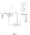
- FIG. 1 is a block diagram showing a schematic configuration of a generator power supply system to which a power conversion device according to Embodiment 1 of the present disclosure is applied.
- a generator power supply system 1 (in the description below, simply referred to as “the power supply system 1") of the present embodiment includes a variable-frequency power generator 2 and AC wiring 3.
- the power generator 2 is connected to the AC wiring 3.
- a breaker (GCB: Generator Circuit Breaker) is provided between the power generator 2 and the AC wiring 3.
- the power generator 2 supplies AC power to an electrical load 5 (in the description below, simply referred to as "the load 5") connected to the AC wiring 3.
- the power supply system 1 further includes DC wiring 6 and an energy storage 7.
- the energy storage 7 is connected to the DC wiring 6.
- a power conversion device 4 includes a power converter 8 and a controller 10.
- the power converter 8 is disposed between the AC wiring 3 and the DC wiring 6.
- the controller 10 controls the power converter 8.
- the power converter 8 is configured to convert AC power inputted to the power converter 8 through the AC wiring 3 into DC power and charge the energy storage 7 with the DC power, and to convert DC power inputted to the power converter 8 through the DC wiring 6, the DC power being discharged from the energy storage 7, into AC power and output the AC power to the AC wiring 3.
- the power converter 8 is constituted by a power conversion circuit that includes a switching element (not shown) such as an IGBT.
- the controller 10 is constituted by, for example, a computer such as a microcontroller, a memory, and/or an electronic circuit. The controller 10 performs power conversion control between the AC wiring 3 and the DC wiring 6 by transmitting, to the power converter 8, a drive signal So for turning ON/OFF the switching element of the power converter 8.
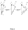
- FIG. 2 show an example in which a vector diagram of a synchronous generator changes due to changes in electric current.
- IIa is a reference vector diagram
- IIb is a vector diagram in a case where an electric current I flowing through the power generator 2 decreases
- IIc is a vector diagram in a case where the electric current I flowing through the power generator 2 increases.
- the internal induced voltage of the power generator 2 is E; the generator reactance of the power generator 2 is X; the electric current flowing through the power generator 2 is I; the voltage of the AC wiring 3 (the system voltage) is V; and the angular velocity of the power generator 2 is ⁇ .
- An internal phase difference angle ⁇ represents the phase difference between the internal induced voltage E of the power generator 2 and the system voltage V, which is the terminal voltage of the power generator 2.
- the internal phase difference angle ⁇ increases in accordance with an increase in the load power, and decreases in accordance with a decrease in the load power.
- the internal phase difference angle ⁇ cannot be directly detected, because, for example, the rotation angle of the power generator 2 cannot be directly detected.
- the present disclosure is characterized by calculating the amount of variation in the internal phase difference angle ⁇ from the system voltage V through arithmetic operation.
- the load power instantaneously increases or decreases
- the internal phase difference angle ⁇ varies in a stepwise manner.
- the amount of such an instantaneous variation in the internal phase difference angle ⁇ is a phase jump amount ⁇ .
- FIG. 3 to FIG. 6 are conceptual diagrams for describing a method of calculating the phase jump amount.
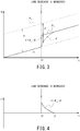
- FIG. 3 is a graph showing temporal changes in the phase (current phase) ⁇ ac of the AC wiring 3 when the load decreases.
- FIG. 3 shows an example case where the rotation speed of the power generator 2 is constant.
- the rotation angle (rotor angle) ⁇ E of the power generator 2 increases linearly with a slope of the angular velocity ⁇ as time elapses.
- the phase ⁇ ac of the AC wiring 3 increases linearly in accordance with an increase in the rotor angle ⁇ E .
- the internal phase difference angle ⁇ decreases as mentioned above. Specifically, at the time t1, the phase ⁇ ac of the AC wiring 3 increases in a stepwise manner. The amount of the increase in the phase ⁇ ac of the AC wiring 3 is the phase jump amount ⁇ .
- the present embodiment adopts the concept of a "virtual phase ⁇ ", which follows temporal changes in the phase ⁇ ac in a lagging manner.
- the virtual phase ⁇ has a value that is slightly lagged from the current phase ⁇ ac .
- the virtual phase ⁇ follows the current phase ⁇ ac with a time lag so as to eliminate the difference between the current phase ⁇ ac and the virtual phase ⁇ .
- the virtual phase ⁇ increases non-linearly from the time t1, at which a load variation occurs.
- the virtual phase ⁇ gradually becomes closer to the current phase ⁇ ac , and the difference between the virtual phase ⁇ and the current phase ⁇ ac becomes 0 again.
- FIG. 4 is a graph showing temporal changes in the phase jump amount ⁇ of FIG. 3 .
- the phase jump amount ⁇ is 0.
- the phase jump amount ⁇ takes a predetermined positive value (i.e., the phase jump amount ⁇ occurs in the leading direction). Thereafter, the phase jump amount ⁇ decreases logarithmic-functionally, and returns to 0.
- FIG. 5 is a graph showing temporal changes in the phase (current phase) ⁇ ac of the AC wiring 3 when the load increases. Also in FIG. 5 , the rotor angle ⁇ E , and the phase ⁇ ac of the AC wiring 3 during a period of no load variation, increase linearly as time elapses.
- the internal phase difference angle ⁇ increases as mentioned above. Specifically, at the time t1, the phase ⁇ ac of the AC wiring 3 decreases in a stepwise manner. The amount of the decrease in the phase ⁇ ac of the AC wiring 3 is the phase jump amount ⁇ .
- the virtual phase ⁇ decreases non-linearly from the time t1, at which a load variation occurs.
- the virtual phase ⁇ gradually becomes closer to the current phase ⁇ ac , and the difference between the virtual phase ⁇ and the current phase ⁇ ac becomes 0 again.
- FIG. 6 is a graph showing temporal changes in the phase jump amount ⁇ of FIG. 5 .
- the phase jump amount ⁇ is 0.
- the phase jump amount ⁇ takes a predetermined negative value (i.e., the phase jump amount ⁇ occurs in the lagging direction).
- the phase jump amount ⁇ increases logarithmic-functionally, and returns to 0.
- the controller 10 of the present embodiment supplies active power to the AC wiring 3 (i.e., discharges the energy storage 7), whereas when the phase jump amount ⁇ takes a negative value, the controller 10 controls the power converter 8 to absorb the active power of the AC wiring 3 (i.e., charges the energy storage 7).
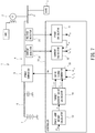
- FIG. 7 is a block diagram showing a schematic configuration of a control system of the power conversion device of Embodiment 1.
- the controller 10 shown in FIG. 7 is configured as a controller of a current-control type.
- the controller 10 of a current-control type controls the power converter 8 by using alternating currents I d and I q of the AC wiring as control elements. Therefore, the power conversion device 4 includes a current detector 21, which detects an output current outputted from the power converter 8 to the AC wiring 3.
- the current detector 21 detects instantaneous current values i a , i b , and i c of the respective phases of a three-phase alternating current.
- a CT Current Transformer
- the controller 10 calculates the current phase ⁇ ac from the system voltage at the AC wiring 3 side of the power converter 8. Therefore, the power conversion device 4 includes a voltage detector 22, which detects the system voltage at the AC wiring 3 side of the power converter 8.
- the voltage detector 22 detects instantaneous voltage values v a , v b , and v c of the respective phases of a three-phase alternating current.
- a PT Pitential Transformer
- the values detected by the detectors 21 and 22 are inputted to the controller 10.
- the controller 10 includes the following control blocks: a phase calculator 11; a current calculator 12; a phase jump amount calculator 13; a target current value calculator 14; and a drive signal generator 15.
- the phase calculator 11 calculates the current phase ⁇ ac of the AC wiring 3 by known PLL (Phase Lock Loop) operation from the system voltage (the instantaneous voltage values v a , v b , and v c of the respective phases) detected by the voltage detector 22.
- PLL Phase Lock Loop
- the current calculator 12 calculates electric currents of the respective coordinate axes in an alternating-current rotating coordinate system (i.e., d-axis current I d and q-axis current I q ) from the instantaneous current values i a , i b , and i c of the respective phases, which are detected by the current detector 21, and the phase ⁇ ac calculated by the phase calculator 11, by using an equation shown below.
- d-axis current I d and q-axis current I q alternating-current rotating coordinate system
- the phase jump amount calculator 13 calculates a phase difference ⁇ ac - ⁇ between the current phase ⁇ ac and the virtual phase ⁇ as a phase jump amount ⁇ .
- FIG. 8 shows one exemplary mode of calculation performed by the phase jump amount calculator of the present embodiment.
- the phase jump amount calculator 13 calculates the virtual phase ⁇ , which follows temporal changes in the current phase ⁇ ac in a lagging manner, and calculates the phase difference ⁇ ac - ⁇ between the current phase ⁇ ac and the virtual phase ⁇ as the phase jump amount ⁇ .
- the phase jump amount calculator 13 calculates the virtual phase ⁇ by performing phase lock loop (PLL) operation on the current phase ⁇ ac .
- PLL phase lock loop
- the phase jump amount calculator 13 includes an estimator 32 and an integrator 33.
- the estimator 32 estimates a past system frequency ⁇ of the AC wiring 3 from the phase jump amount ⁇ in a past time.
- the integrator 33 calculates, as the virtual phase ⁇ , a past phase by integrating the estimated past system frequency ⁇ .
- the estimator 32 is configured as a PI controller.
- a transfer function G 1 (s) of the PI controller is represented by an equation shown below by using a gain K PLL and an integral time T PLL .
- phase jump amount calculator 13 is configured to integrate the past phase jump amount ⁇ twice by the estimator 32 and the integrator 33.
- the current phase ⁇ ac and the virtual phase ⁇ are inputted to a subtracter 31.
- the phase jump amount calculator 13 outputs a phase difference ⁇ ac - ⁇ that is obtained by subtraction by the subtracter 31 as a phase jump amount ⁇ .
- the phase jump amount ⁇ calculated by the subtracter 31 is inputted to the estimator 32 again as a past phase jump amount ⁇ .
- the virtual phase ⁇ which follows temporal changes in the current phase ⁇ ac in a lagging manner, can be calculated from the current phase ⁇ ac by relatively easy calculation.
- FIG. 9 shows one exemplary mode of calculation performed by the target current value calculator of the present embodiment.
- the target current value calculator 14 calculates a target current value I d ref by applying predetermined filters to the phase jump amount ⁇ calculated by the phase jump amount calculator 13 and multiplying an output from the filters by a predetermined proportional gain (-K).
- the target current value calculator 14 of the present embodiment includes a first filter 34, a second filter 35, and a gain multiplier 36.
- the first filter 34 is constituted by a low-pass filter.
- the transfer function of the first filter 34 is expressed as 1 / (1 + T LPF ⁇ s) by using a time constant T LPF .
- the second filter 35 is constituted by a high-pass filter.
- the transfer function of the second filter 35 is expressed as T HPF ⁇ s / (1 + T HPF ⁇ s) by using a time constant T HPF .
- the controller 10 applies the first filter 34 and the second filter 35 to the phase jump amount ⁇ , and multiplies an output from the first filter 34 and the second filter 35 by a proportional gain (-K) to calculate a target value I d ref of the d-axis current outputted from the power converter 8 to the AC wiring 3. Further, the controller 10 outputs a predetermined fixed value (in the example of FIG. 9 , outputs 0) from a fixed value outputter 37 as a target value I q_ref of the q-axis current.
- a predetermined fixed value in the example of FIG. 9 , outputs 0
- response characteristics to the phase jump amount ⁇ can be adjusted, which makes it possible to generate a more optimized drive signal So. For example, in a case where a load variation occurs periodically, suppressing effects in response to the load variation can be increased by setting the time constants T LPF and T HPF of the filters such that the filters have high sensitivity in the load-varying regions.
- the target current value calculator 14 may include either one of the first filter 34 or the second filter 35.
- the target current value calculator 14 may further include a different filter other than the first filter 34 and the second filter 35 (e.g., a band-pass filter). Further, in a case where the filtering process is unnecessary, direct conversion into the target current value I d ref may be performed without the filtering process.
- the phase jump amount ⁇ becomes a positive value (the phase jump amount ⁇ occurs in the leading direction), whereas if the load increases, the phase jump amount ⁇ becomes a negative value (the phase jump amount ⁇ occurs in the lagging direction).
- the controller 10 outputs a negative value as the target value I d ref of the d-axis current, whereas if the load increases, the controller 10 outputs a positive value as the target value I d ref of the d-axis current.
- the drive signal generator 15 generates the drive signal So to the power converter 8, which is a signal for adjusting active power that is inputted to/outputted from the power converter 8 so as to suppress the phase jump amount ⁇ .
- the controller 10 generates the drive signal So for performing feedback control such that the alternating currents I d and I q outputted from the power converter 8 to the AC wiring 3 are adjusted to the target current values I d ref and I q_ref calculated by the target current value calculator 14. Therefore, the alternating currents I d and I q outputted to the AC wiring 3, the current phase ⁇ ac , and the target current values I d ref and I q_ref are inputted to the drive signal generator 15.
- the drive signal generator 15 calculates target voltage values V d_ref and V q_ref from the target current values I d_ref and I q_ref , respectively, by using equations shown below.
- each of K d and K q is a predetermined gain
- each of T id and T iq is a predetermined time constant.
- V d _ ref K d 1 + 1 T id ⁇ s I d _ ref ⁇ I d
- V q _ ref K q 1 + 1 T iq ⁇ s I q _ ref ⁇ I q
- the drive signal generator 15 calculates target values V a_ref , V b_ref , and V c_ref of respective instantaneous voltages V a , V b , and V c of the three-phase AC wiring 3 from the target voltage values V d_ref and V q_ref by using an equation shown below.
- V a _ ref V b _ ref V c _ ref 2 3 cos ⁇ ac ⁇ sin ⁇ ac cos ⁇ ac ⁇ 2 3 ⁇ ⁇ sin ⁇ ac ⁇ 2 3 ⁇ cos ⁇ ac ⁇ 4 3 ⁇ ⁇ sin ⁇ ac ⁇ 4 3 ⁇ V d _ ref V q _ ref
- a load variation is detected depending on the phase jump amount ⁇ , which is calculated based on temporal changes in the phase ⁇ ac of the AC wiring 3.
- the phase jump amount ⁇ indicates a change in the internal phase difference angle ⁇ of the power generator 2, and is a value dependent on an active power load of the power generator 2.
- the controller 10 controls the power converter 8 such that in a case where the phase jump amount ⁇ occurs in the leading direction, the power converter 8 absorbs the active power of the AC wiring 3, whereas in a case where the phase jump amount ⁇ occurs in the lagging direction, the power converter 8 supplies active power to the AC wiring 3. In this manner, a power variation, a voltage variation, and a phase jump of the AC wiring 3 due to a load variation are suppressed.
- the impedance and excitation circuit responsiveness of the variable-frequency power generator 2 vary greatly depending on the frequency. For this reason, in some control modes for stabilization, it is possible that the stability cannot be entirely maintained in all the regions.
- active control of, for example, a governor (speed governor) and an AVR (automatic voltage regulator) of the power generator 2 need not be performed, but passive control is performed so as to suppress a transient variation occurring in the AC wiring 3. For this reason, the control by the power conversion device 4 does not interfere with the control of, for example, the governor and the AVR of the power generator 2. Therefore, the control and adjustments by the power conversion device 4 can be readily performed.
- a period in which electric power is supplied from the power converter 8 to the AC wiring 3, and a period in which the electric power of the AC wiring 3 is absorbed by the power converter 8, are each a short period of time in which a phase jump occurs due to a load variation (the phase jump amount ⁇ is not 0), i.e., a period from the time t1 to the time t2 shown in FIG. 4 and FIG. 6 . Therefore, the energy storage 7 connected to the DC wiring 6 is required to have only a minimum necessary capacity, which makes it possible to suppress an increase in the size of the energy storage 7. For this reason, the energy storage 7 may be constituted by, for example, a secondary battery. Alternatively, the energy storage 7 may be constituted by an electric double-layer capacitor.
- a conventional power conversion device capable of adjusting power supply and demand such as the one disclosed in Patent Literature 2
- an energy storage connected to the direct current side needs to have a great capacity. Therefore, if such a power conversion device is directly applied to a generator power supply system of, for example, a mobile vehicle to perform load power compensation, the system becomes large-sized, which is not preferable in some cases.
- the power conversion device 4 of the present embodiment the energy storage 7 connected to the DC wiring 6 is required to have only a minimum necessary capacity as mentioned above. Therefore, the power conversion device 4 of the present embodiment is more suitably applicable as a power conversion device for suppressing a load variation in the power supply system 1, which has a size limitation.
- Embodiment 2 of the present disclosure a power conversion device according to Embodiment 2 of the present disclosure is described.
- the same configuration elements as those described in Embodiment 1 are denoted by the same reference signs as those used in Embodiment 1, and the description of such configuration elements is omitted.
- FIG. 10 is a block diagram showing a schematic configuration of a control system of the power conversion device according to Embodiment 2 of the present disclosure.
- a power conversion device 4B of the present embodiment also includes the power converter 8, the current detector 21, the voltage detector 22, and a controller 10B.
- the controller 10B is also configured as a controller of a current-control type.
- the controller 10B of the present embodiment is different from the controller 10 of Embodiment 1 in that the controller 10B performs virtual synchronous phase modifier model control of the power converter 8.
- the virtual synchronous phase modifier model control is defined herein as a control mode that is on an assumption that a virtual synchronous phase modifier is connected instead of the power conversion device 4B, and based on the assumption, arithmetic operations are performed. Specifically, a value based on a virtual inertia moment (an inertia constant), an impedance (a reactance), and an internal electromotive force voltage in the virtual synchronous phase modifier are stored in the controller 10B as operation parameters.
- the virtual synchronous phase modifier in the present embodiment does not have a virtual motive power source, and an exciting voltage Ef is a fixed value (in this example, 1 PU (Per Unit)). Accordingly, the power conversion device 4B equivalently acts as a synchronous phase modifier with a constant exciting voltage.
- the controller 10B of the present embodiment also includes the phase calculator 11, the current calculator 12, and the drive signal generator 15.
- the controller 10B further includes a phase jump amount calculator 13B instead of the phase jump amount calculator 13 of Embodiment 1.
- the phase jump amount calculator 13B includes an angular velocity calculator 41 and an integrator 42.
- the angular velocity calculator 41 calculates an angular velocity ⁇ V in the virtual synchronous phase modifier by using active power P ac of the AC wiring 3 and a value (an inertia constant M v ) that is based on a virtual inertia moment in the virtual synchronous phase modifier.
- the integrator 42 calculates, as a virtual phase ⁇ , a phase in the virtual synchronous phase modifier by integrating the angular velocity ⁇ V .
- the controller 10B further includes a target current value calculator 14B instead of the target current value calculator 14 of Embodiment 1.
- the target current value calculator 14B calculates target current values I d ref and I q_ref from voltage differences ⁇ V d and ⁇ V q between internal electromotive force voltages Ef d and Ef q in the virtual synchronous phase modifier and system voltages V d and V q detected by the power detector 22.
- the controller 10B further includes a voltage calculator 16 and an active power calculator 17.
- the current detector 21, the voltage detector 22, the phase calculator 11, the current calculator 12, the voltage calculator 16, and the active power calculator 17 constitute an active power obtainer that obtains active power P ac at the AC wiring 3 side of the power converter 8.
- the voltage calculator 16 calculates voltages of the respective coordinate axes in an AC voltage rotating coordinate system (i.e., d-axis voltage V d and q-axis voltage V q ) from the current phase ⁇ ac calculated by the phase calculator 11, by using an equation shown below.
- V d V q 2 3 cos ⁇ ac cos ⁇ ac ⁇ 2 3 ⁇ cos ⁇ ac ⁇ 4 3 ⁇ ⁇ sin ⁇ ac ⁇ sin ⁇ ac ⁇ 2 3 ⁇ ⁇ sin ⁇ ac ⁇ 4 3 ⁇ v a v b v c
- the active power calculator 17 calculates active power P ac and reactive power Q ac , which are outputted from the power converter 8 to the AC wiring 3, from voltages V d and V q calculated by the voltage calculator 16 and electric currents I d and I q calculated by the current calculator 12, by using equations shown below. It should be noted that since the reactive power Q ac is not used in the present embodiment, the calculation of the reactive power Q ac need not be performed.
- FIG. 11 shows one exemplary mode of calculation performed by the phase jump amount calculator of the present embodiment.
- the current phase ⁇ ac and the active power P ac are inputted to the phase jump amount calculator 13B of the present embodiment.
- the active power P ac is inputted to a phase compensator 44 described below.
- the phase compensator 44 outputs phase-compensated active power, which is inputted to the angular velocity calculator 41.
- the angular velocity calculator 41 applies a transfer function G 2 (s) to the phase-compensated active power.
- the transfer function G 2 (s) is represented by an equation shown below.
- ⁇ o is an angular velocity in a steady state
- M V is an inertia constant that is based on an inertia moment in the virtual synchronous phase modifier.
- the transfer function G 2 (s) in Math. 8 is, in other words, a function of integrating the active power P ac to calculate the degree of increase/decrease in the angular velocity ⁇ V , thereby calculating the angular velocity ⁇ V .
- the angular velocity ⁇ V calculated by the angular velocity calculator 41 is integrated by the integrator 42, and thereby the phase in the virtual synchronous phase modifier is calculated. Consequently, the phase jump amount calculator 13B of the present embodiment is configured to integrate the active power P ac twice by the angular velocity calculator 41 and the integrator 42. In the present embodiment, the output from the integrator 42 is used as the virtual phase ⁇ .
- the current phase ⁇ ac and the virtual phase ⁇ are inputted to a subtracter 43.
- the phase jump amount calculator 13B outputs a phase difference ⁇ ac - ⁇ that is obtained by subtraction by the subtracter 43 as a phase jump amount ⁇ .
- the virtual phase ⁇ which follows temporal changes in the current phase ⁇ ac in a lagging manner, can be calculated relatively easily by taking account of a value (inertia constant M V ) that is based on a virtual inertia moment occurring in the virtual synchronous phase modifier.
- the phase jump amount calculator 13B includes the phase compensator 44, which phase-compensates the active power P ac before the angular velocity calculator 41 calculates the angular velocity ⁇ V from the active power P ac .
- the virtual synchronous phase modifier model adopted by the present embodiment causes the power converter 8 to operate on an assumption that synchronizing power occurs between the power converter 8 and the power generator 2 (the AC wiring 3).
- the virtual synchronous phase modifier at the time is an ideal synchronizer, and has no damping element. For this reason, it is possible that a response to the active power P ac , which is a feedback element, becomes oscillating.
- a damping effect can be in advance added to the active power P ac , which is used for calculating the virtual phase ⁇ . Therefore, an electric power compensation response to a load variation can be prevented from becoming oscillating.
- FIG. 12 shows one exemplary mode of calculation performed by the target current value calculator of the present embodiment.
- the phase jump amount ⁇ and the voltages V d and V q are inputted to the target current value calculator 14B of the present embodiment.
- the inversion amount ⁇ of the phase jump amount ⁇ is inputted to an internal electromotive force voltage calculator 46.
- the internal electromotive force voltages Ef d and Ef q are represented by equations shown below.
- the calculated internal electromotive force voltages Ef d and Ef q and the voltages V d and V q calculated by the voltage calculator 16 are inputted to an impedance model calculator 47.
- the impedance model calculator 47 calculates voltage differences ⁇ V d and ⁇ V q by using equations shown below. Each of the voltage differences ⁇ V d and ⁇ V q is a voltage drop due to a virtual impedance in the virtual synchronous phase modifier.
- the impedance model calculator 47 further calculates target current values I d ref and I q_ref from the obtained voltage differences ⁇ V d and ⁇ V q and a value X s by using equations shown below.
- the value X s is based on a virtual reactance in the virtual synchronous phase modifier.
- the drive signal generator 15 generates the drive signal So to the power converter 8, which is a signal for adjusting active power that is inputted to/outputted from the power converter 8 so as to suppress the phase jump amount ⁇ .
- the controller 10B generates the drive signal So for performing feedback control such that the alternating currents I d and I q outputted from the power converter 8 to the AC wiring 3 are adjusted to the target current values I d_ref and I q_ref calculated by the target current value calculator 14B.
- a load variation is detected depending on the phase jump amount ⁇ , which is calculated based on temporal changes in the phase ⁇ ac of the AC wiring 3.
- the controller 10B controls the power converter 8 such that in a case where the phase jump amount ⁇ occurs in the leading direction, the power converter 8 absorbs the active power of the AC wiring 3, whereas in a case where the phase jump amount ⁇ occurs in the lagging direction, the power converter 8 supplies active power to the AC wiring 3. In this manner, a power variation, a voltage variation, and a phase jump of the AC wiring 3 due to a load variation are suppressed.
- the target current value calculator 14B calculates an active current component I d_ref and a reactive current component I q_ref each as a target current value.
- the drive signal So to the power converter 8, which is outputted from the drive signal generator 15, is configured as a drive signal for adjusting active power that is inputted to/outputted from the power converter 8 so as to suppress the phase jump amount ⁇ by using the calculated active current component I d_ref and for adjusting reactive power that is inputted to/outputted from the power converter 8 so as to suppress a voltage variation, more specifically a voltage amplitude variation, by using the calculated reactive current component I q_ref . Therefore, according to the power conversion device 4B of the present embodiment, electric power compensation for a load variation can be performed not only for active power components, but also for reactive power components. This makes it possible to further suppress the voltage variation in the AC wiring 3.
- FIG. 13 is a block diagram showing a power supply system configuration example for the simulation.
- the same configuration elements as those shown in FIG. 1 are denoted by the same reference signs as those used in FIG. 1 , and the description of such configuration elements is omitted.
- a power supply system 1S is used, in which two loads 5b and 5m are connected to the AC wiring 3.
- the base load 5b simulates, for example, a resistor, and is a steady load in which no load variation occurs.
- the base load 5b is 0.25 PU.
- the varying load 5m simulates, for example, a motor, and is a load in which load variations occur.
- powering consumption of electric power
- regeneration generation of electric power
- the peak during the powering is 0.5 PU
- the peak during the regeneration is -0.3 PU.
- the power generator 2 operates constantly at a predetermined frequency.
- Examples 1 and 2 will be described below.
- load variations of the varying load 5m are caused in the above-described manner, and simulation results obtained in Examples 1 and 2 are compared with simulation results obtained in Comparative Example in which electric power compensation is not performed.
- Comparative Example is the simulation in a case where electric power compensation is not performed in the power supply system 1S of FIG. 13 .
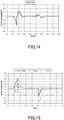
- FIG. 14 to FIG. 16 are graphs showing simulation results in the case where electric power compensation is not performed.
- FIG. 14 is a graph showing temporal changes in the system voltage V bus .
- FIG. 15 is a graph showing temporal changes in various active powers P gen , P load , and P mot .
- FIG. 16 is a graph showing temporal changes in various reactive powers Q gen , Q load , and Q mot .
- the system voltage V bus decreases rapidly from 1 PU, and thereafter increases to become higher than 1 PU. This is because, as shown in FIG. 2 , the load current I of the varying load 5m increases rapidly due to the start of the powering, and in accordance therewith, the voltage decreases. Then, when the powering ends, the load current I of the varying load 5m decreases rapidly, and consequently, the voltage increases.
- the system voltage V bus varies (increases and decreases).
- varying load active power P mot of the varying load 5m indicates the load variations.
- the varying load active power P mot increases by approximately 0.45 PU, and consequently, the power generator active power P gen also increases by approximately 0.4 PU.
- the base load active power P load also varies, which indicates that the influence of the varying load 5m affects the base load 5b. The same is true for the load variation that occurs due to the regeneration.
- Example 1 is the simulation in a case where the electric power compensation based on the control mode of Embodiment 1 is performed in the power supply system 1S of FIG. 13 .
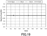
- FIG. 17 to FIG. 19 are graphs showing simulation results in the case where the electric power compensation of Embodiment 1 is performed.
- FIG. 17 to FIG. 19 in Example 1 correspond to FIG. 13 to FIG. 15 in Comparative Example.
- FIG. 17 is a graph showing temporal changes in the system voltage V bus .
- FIG. 18 is a graph showing temporal changes in various active powers P gen , P load , P mot , and P stb .
- FIG. 19 is a graph showing temporal changes in various reactive powers Q gen , Q load , Q mot , and Q stb .
- the system voltage V bus still varies as a result of the load variation occurring in the varying load 5m due to the powering.
- the variation range in this case is sufficiently less than the variation range in Comparative Example shown in FIG. 14 , in which electric power compensation is not performed. This indicates that the voltage variation due to the load variation is suppressed by the electric power compensation.
- Example 1 the varying load active power P mot of the varying load 5m changes in the same manner as in Comparative Example shown in FIG. 15 (i.e., the same load variations occur). However, it is understood that, in Example 1, changes in the power generator active power P gen that occur in accordance with the changes in the varying load active power P mot are less than those in Comparative Example.
- Power conversion device active power P stb in FIG. 18 indicates active power outputted from the power converter 8. Positive values indicate that active power is supplied to the AC wiring 3, whereas negative values indicate that active power is absorbed from the AC wiring 3.
- FIG. 18 shows that when the varying load active power P mot increases rapidly at the start of the powering, the power conversion device active power P stb becomes a positive value. Therefore, it is understood that the power converter 8 supplies active power to the AC wiring 3 in accordance with the rapid increase in the varying load active power P mot . Consequently, the maximum increase amount of the power generator active power P gen , and the increase amount of the power generator active power P gen per unit time, are reduced compared to Comparative Example.
- FIG. 18 also shows that when the varying load active power P mot decreases rapidly at the end of the powering, the power conversion device active power P stb becomes a negative value. Therefore, it is understood that the power converter 8 absorbs active power from the AC wiring 3 in accordance with the rapid decrease in the varying load active power P mot . Consequently, the decrease amount of the power generator active power P gen per unit time is reduced compared to Comparative Example.
- the power conversion device active power P stb becomes a positive value at the start of the regeneration, and the power conversion device active power P stb becomes a negative value at the end of the regeneration. Consequently, the maximum change amount of the power generator active power P gen per unit time, and the change amount of the power generator active power P gen per unit time, are reduced compared to Comparative Example.
- the waveform of the power generator active power P gen in Example 1 has a smaller peak and a wider full width at half maximum than the waveform of the varying load active power P mot and the waveform of the power generator active power P gen in Comparative Example, in which electric power compensation is not performed.
- the variation range (the maximum value) of the active power P gen , and the variation range of the active power P gen per unit time are both reduced in the power generator 2.
- a time during which the power conversion device 4 supplies electric power to the AC wiring 3 i.e., a time during which P stb takes a positive value
- a time during which electric power is supplied from the AC wiring 3 i.e., a time during which P stb takes a negative value
- the energy storage 7 connected to the power conversion device 4S need not have a great capacity.
- the energy storage 7 can be realized by an energy storage having a minimum necessary capacity.
- Example 2 is the simulation in a case where the electric power compensation based on the control mode of Embodiment 2 is performed in the power supply system 1S of FIG. 13 .
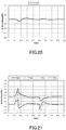
- FIG. 20 to FIG. 22 are graphs showing simulation results in the case where the electric power compensation of Embodiment 2 is performed.
- FIG. 20 to FIG. 22 in Example 2 correspond to FIG. 13 to FIG. 15 in Comparative Example.
- FIG. 20 is a graph showing temporal changes in the system voltage V bus .
- FIG. 21 is a graph showing temporal changes in various active powers P gen , P load , P mot , and P stb .
- FIG. 22 is a graph showing temporal changes in various reactive powers Q gen , Q load , Q mot , and Q stb .
- the waveforms of the respective active powers P gen , P load , P mot , and P stb in Example 2 are substantially the same as those waveforms in Example 1. Therefore, it is understood that by performing the electric power compensation based on the control mode of Embodiment 2 for the load variations of the varying load 5m, the variation range (the maximum value) of the active power P gen , and the variation range of the active power P gen per unit time, are both reduced in the power generator 2.
- the active power P ac is phase-compensated before the angular velocity ⁇ V is calculated by using the active power P ac .
- the power conversion device active power P stb and the power generator active power P gen converge within a short period of time, which is as short as in Example 1, without becoming oscillating for the load variations.
- Example 2 the electric power compensation is performed not only for active power components, but also for reactive power components.
- the power conversion device reactive power Q stb changes in accordance with changes in the power conversion device active power P stb .
- the power generator reactive power Q gen changes in accordance with changes in the power conversion device reactive power Q stb .
- the power generator reactive power Q gen has a waveform inverted from the waveform of the power conversion device reactive power Q stb .
- Example 2 the electric power compensation is performed for both active and reactive power components. Consequently, as shown in FIG. 20 , the variation range of the system voltage V bus is less than that in Example 1 shown in FIG. 17 , in which the electric power compensation is performed only for active power components. From this, it is understood that since the electric power compensation is performed also for reactive power components, voltage variations (voltage amplitude variations) due to the load variations are further suppressed.
- the above embodiments have described the case in which the AC wiring 3 in the power supply system to which the power conversion device is applied is a three-phase system.
- the present disclosure is not thus limited.
- the same power conversion devices as those described in the above embodiments are each applicable to such a power supply system, although in such a case, methods by which to perform the various calculations differ in accordance with the type of the system of the AC wiring 3.
- the power conversion device of the present disclosure is suitably applicable to any power supply system including a power generator, for example, applicable to power supply systems of mobile vehicles, such as hybrid propulsion ships, normal ships, and aircrafts, private power generation systems, etc.
- At least part of the configuration (the control mode) of Embodiment 1 and at least part of the configuration (the control mode) of Embodiment 2 may be combined with each other.
- the controller may be configured in such a manner that the phase jump amount calculator 13 of Embodiment 1 and the target current value calculator 14B of Embodiment 2 are combined with each other.
- the controller may be configured in such a manner that the phase jump amount calculator 13B of Embodiment 2 and the target current value calculator 14 of Embodiment 1 are combined with each other.
- variable-frequency power generator is taken as one example of the power generator 2.
- the power conversion device of the present disclosure is applicable also to a power supply system that includes a power generator different from a variable-frequency power generator (e.g., a frequency-controllable power generator).
- a power conversion device includes: a power converter disposed between AC wiring, to which a power generator and an electrical load are connected, and DC wiring, to which an energy storage is connected, the power converter being configured to convert AC power inputted to the power converter through the AC wiring into DC power and charge the energy storage with the DC power, and to convert DC power inputted to the power converter through the DC wiring, the DC power being discharged from the energy storage, into AC power and output the AC power to the AC wiring; a voltage detector that detects a system voltage at the AC wiring side of the power converter; and a controller that performs power conversion control between the AC wiring and the DC wiring by transmitting a drive signal to the power converter.
- the controller includes: a phase calculator that calculates a current phase from the system voltage detected by the voltage detector; a phase jump amount calculator that calculates a virtual phase that follows temporal changes in the current phase in a lagging manner, and calculates a phase difference between the current phase and the virtual phase as a phase jump amount; and a drive signal generator that generates the drive signal to the power converter, which is a signal for adjusting active power that is inputted to/outputted from the power converter so as to suppress the phase jump amount.
- a load variation is detected depending on the phase jump amount, which is calculated based on temporal changes in the phase of the AC wiring.
- the phase jump amount indicates a change in an internal phase difference angle of the power generator, and is a value dependent on an active power load of the power generator. Therefore, by adjusting the active power that is inputted to/outputted from the power converter based on the phase jump amount, electric power compensation for the load variation can be performed without depending on a frequency variation.
- the phase jump amount calculator may be configured to calculate the virtual phase by integrating twice the phase jump amount in a past time.
- the phase jump amount calculator may include: an estimator that estimates a past system frequency of the AC wiring from the phase jump amount in a past time; and an integrator that calculates, as the virtual phase, a past phase by integrating the estimated past system frequency. According to this configuration, by performing the calculation of estimating the past phase, the virtual phase, which follows temporal changes in the current phase in a lagging manner, can be calculated from the current phase by relatively easy calculation.
- the power conversion device may include an active power obtainer that obtains active power at the AC wiring side of the power converter.
- the phase jump amount calculator may include: an angular velocity calculator that calculates, on an assumption that a virtual synchronous phase modifier is connected instead of the power conversion device, an angular velocity in the virtual synchronous phase modifier by using the obtained active power and a value that is based on a virtual inertia moment in the virtual synchronous phase modifier; and an integrator that calculates, as the virtual phase, a phase in the virtual synchronous phase modifier by integrating the angular velocity.
- the virtual phase which follows temporal changes in the current phase in a lagging manner, can be calculated relatively easily.
- the phase jump amount calculator may include a phase compensator that phase-compensates the active power, and the phase jump amount calculator may be configured to input the phase-compensated active power to the angular velocity calculator. According to this configuration, by means of the phase compensator, a damping effect can be in advance added to the active power, which is used for calculating the virtual phase. Therefore, an electric power compensation response to a load variation can be prevented from becoming oscillating.
- the power conversion device may include a target current value calculator that calculates a target current value by applying a predetermined filter to the phase jump amount and multiplying an output from the filter by a predetermined proportional gain.
- the drive signal generator may generate the drive signal such that an alternating current outputted from the power converter to the AC wiring is adjusted to the target current value. According to this configuration, by applying the filter to the phase jump amount, response characteristics to the phase jump amount can be adjusted, which makes it possible to generate a more optimized drive signal.
- the power conversion device may include a target current value calculator that calculates, on an assumption that a virtual synchronous phase modifier is connected instead of the power conversion device, a target current value from a voltage difference between an internal electromotive force voltage in the virtual synchronous phase modifier and the system voltage detected by the voltage detector.
- the drive signal generator may generate the drive signal such that an alternating current outputted from the power converter to the AC wiring is adjusted to the target current value.
- the target current value calculator may be configured to calculate an active current component and a reactive current component each as the target current value.
- the drive signal generator may be configured to generate the drive signal for adjusting the active power that is inputted to/outputted from the power converter so as to suppress the phase jump amount by using the calculated active current component and for adjusting reactive power that is inputted to/outputted from the power converter so as to suppress a voltage variation by using the calculated reactive current component.
- the present disclosure is useful for performing electric power compensation for a load variation without depending on a frequency variation.
Landscapes
- Engineering & Computer Science (AREA)
- Power Engineering (AREA)
- Inverter Devices (AREA)
- Supply And Distribution Of Alternating Current (AREA)
- Control Of Eletrric Generators (AREA)
- Rectifiers (AREA)
Abstract
Description
- The present disclosure relates to power conversion devices.
- There have been known variable-frequency (VF) generator power supply systems that are used in, for example, mobile vehicles such as ships and aircrafts. In such a generator power supply system, there are cases where a load variation (a variation in load power) that is relatively great for the power generator capacity occurs within a short period of time. For example, in some cases, the range of such a load variation reaches approximately the half of the power generator capacity.
- In order to suppress such a load variation, it is conceivable to connect a power conversion device to AC wiring to which the power generator and the load are connected, and perform load power compensation. Conventionally, for performing load power compensation with use of a power conversion device, there are known methods that utilize a frequency variation caused by a load variation (see
Patent Literatures 1 to 3 listed below). -
- PTL 1:
Japanese Laid-Open Patent Application Publication No. 2012-143018 - PTL2:
Japanese Patent No. 5956991 - PTL 3:
Japanese Patent No. 5631712 - However, in a variable-frequency generator power supply system, such a frequency variation caused by a load variation cannot be utilized. In general, since a prime mover that is used for driving the power generator in the variable-frequency generator power supply system is sufficiently greater than the power generator, even if a load variation occurs, a frequency variation does not easily occur in the AC wiring. In addition, since the rotation speed of the prime mover is not constant, a change in the rotation speed of the prime mover causes a change in frequency.
- For these reasons, in a variable-frequency generator power supply system, load power compensation cannot be performed based on a frequency variation of the AC wiring. Therefore, the configurations disclosed by
Patent Literatures 1 to 3 listed above cannot be applied to a variable-frequency generator power supply system. - There is another conceivable method, which is to perform load power compensation by utilizing a voltage amplitude variation caused by a load variation. However, this method cannot be adopted, because, for example, when a load variation has occurred, including the case of becoming a no load state, there is a possibility that a detected voltage amplitude and load power do not transiently coincide with each other, and thereby system destabilization may be caused.
- The present disclosure has been made to solve the above-described problems. An object of the present disclosure is to provide a power conversion device that is capable of performing electric power compensation for a load variation without depending on a frequency variation.
- A power conversion device according to one aspect of the present disclosure includes: a power converter disposed between AC wiring, to which a power generator and an electrical load are connected, and DC wiring, to which an energy storage is connected, the power converter being configured to convert AC power inputted to the power converter through the AC wiring into DC power and charge the energy storage with the DC power, and to convert DC power inputted to the power converter through the DC wiring, the DC power being discharged from the energy storage, into AC power and output the AC power to the AC wiring; a voltage detector that detects a system voltage at the AC wiring side of the power converter; and a controller that performs power conversion control between the AC wiring and the DC wiring by transmitting a drive signal to the power converter. The controller includes: a phase calculator that calculates a current phase from the system voltage detected by the voltage detector; a phase jump amount calculator that calculates a virtual phase that follows temporal changes in the current phase in a lagging manner, and calculates a phase difference between the current phase and the virtual phase as a phase jump amount; and a drive signal generator that generates the drive signal to the power converter, which is a signal for adjusting active power that is inputted to/outputted from the power converter so as to suppress the phase jump amount.
- According to the above configuration, a load variation is detected depending on the phase jump amount, which is calculated based on temporal changes in the phase of the AC wiring. The phase jump amount indicates a change in an internal phase difference angle of the power generator, and is a value dependent on an active power load of the power generator. Therefore, by adjusting the active power that is inputted to/outputted from the power converter based on the phase jump amount, electric power compensation for the load variation can be performed without depending on a frequency variation.
- The present disclosure makes it possible to perform electric power compensation for a load variation without depending on a frequency variation.
-
-
FIG. 1 is a block diagram showing a schematic configuration of a generator power supply system to which a power conversion device according toEmbodiment 1 of the present disclosure is applied. -
FIG. 2 shows an example in which a vector diagram of a synchronous generator changes due to changes in electric current. -
FIG. 3 is a graph showing temporal changes in the phase (current phase) of AC wiring when the load decreases. -
FIG. 4 is a graph showing temporal changes in a phase jump amount ofFIG. 3 . -
FIG. 5 is a graph showing temporal changes in the phase (current phase) of the AC wiring when the load increases. -
FIG. 6 is a graph showing temporal changes in a phase jump amount ofFIG. 5 . -
FIG. 7 is a block diagram showing a schematic configuration of a control system of the power conversion device ofEmbodiment 1. -
FIG. 8 shows one exemplary mode of calculation performed by a phase jump amount calculator of the present embodiment. -
FIG. 9 shows one exemplary mode of calculation performed by a target current value calculator of the present embodiment. -
FIG. 10 is a block diagram showing a schematic configuration of a control system of a power conversion device according toEmbodiment 2 of the present disclosure. -
FIG. 11 shows one exemplary mode of calculation performed by a phase jump amount calculator of the present embodiment. -
FIG. 12 shows one exemplary mode of calculation performed by a target current value calculator of the present embodiment. -
FIG. 13 is a block diagram showing a power supply system configuration example for simulation. -
FIG. 14 is a graph showing simulation results in a case where electric power compensation is not performed. -
FIG. 15 is a graph showing simulation results in the case where electric power compensation is not performed. -
FIG. 16 is a graph showing simulation results in the case where electric power compensation is not performed. -
FIG. 17 is a graph showing simulation results in a case where electric power compensation ofEmbodiment 1 is performed. -
FIG. 18 is a graph showing simulation results in the case where the electric power compensation ofEmbodiment 1 is performed. -
FIG. 19 is a graph showing simulation results in the case where the electric power compensation ofEmbodiment 1 is performed. -
FIG. 20 is a graph showing simulation results in a case where electric power compensation ofEmbodiment 2 is performed. -
FIG. 21 is a graph showing simulation results in the case where the electric power compensation ofEmbodiment 2 is performed. -
FIG. 22 is a graph showing simulation results in the case where the electric power compensation ofEmbodiment 2 is performed. - Hereinafter, embodiments of the present disclosure are described with reference to the drawings. In the drawings, the same elements or elements having the same functions are denoted by the same reference signs, and repeating the same descriptions is avoided below.
- Hereinafter,
Embodiment 1 of the present disclosure is described.FIG. 1 is a block diagram showing a schematic configuration of a generator power supply system to which a power conversion device according toEmbodiment 1 of the present disclosure is applied. A generator power supply system 1 (in the description below, simply referred to as "thepower supply system 1") of the present embodiment includes a variable-frequency power generator 2 andAC wiring 3. Thepower generator 2 is connected to theAC wiring 3. Although not illustrated, a breaker (GCB: Generator Circuit Breaker) is provided between thepower generator 2 and theAC wiring 3. Thepower generator 2 supplies AC power to an electrical load 5 (in the description below, simply referred to as "theload 5") connected to theAC wiring 3. - The
power supply system 1 further includesDC wiring 6 and anenergy storage 7. Theenergy storage 7 is connected to theDC wiring 6. Apower conversion device 4 includes apower converter 8 and acontroller 10. Thepower converter 8 is disposed between theAC wiring 3 and theDC wiring 6. Thecontroller 10 controls thepower converter 8. - The
power converter 8 is configured to convert AC power inputted to thepower converter 8 through theAC wiring 3 into DC power and charge theenergy storage 7 with the DC power, and to convert DC power inputted to thepower converter 8 through theDC wiring 6, the DC power being discharged from theenergy storage 7, into AC power and output the AC power to theAC wiring 3. Thepower converter 8 is constituted by a power conversion circuit that includes a switching element (not shown) such as an IGBT. Thecontroller 10 is constituted by, for example, a computer such as a microcontroller, a memory, and/or an electronic circuit. Thecontroller 10 performs power conversion control between theAC wiring 3 and theDC wiring 6 by transmitting, to thepower converter 8, a drive signal So for turning ON/OFF the switching element of thepower converter 8. - Hereinafter, a phase jump amount used in the present embodiment is described.
FIG. 2 show an example in which a vector diagram of a synchronous generator changes due to changes in electric current. InFIG. 2 , IIa is a reference vector diagram; IIb is a vector diagram in a case where an electric current I flowing through thepower generator 2 decreases; and IIc is a vector diagram in a case where the electric current I flowing through thepower generator 2 increases. - As shown in
FIG. 1 andFIG. 2 , the internal induced voltage of thepower generator 2 is E; the generator reactance of thepower generator 2 is X; the electric current flowing through thepower generator 2 is I; the voltage of the AC wiring 3 (the system voltage) is V; and the angular velocity of thepower generator 2 is ω. An internal phase difference angle δ represents the phase difference between the internal induced voltage E of thepower generator 2 and the system voltage V, which is the terminal voltage of thepower generator 2. The description below takes only active power components into account. The description below is given assuming that instantaneous load variations occur. Accordingly, the internal induced voltage E of thepower generator 2 is assumed to be constant. - In the reference vector diagram IIa, when a load current Iload flowing to the
load 5 decreases due to a decrease in the load power, the electric current I flowing through thepower generator 2 also decreases. As a result, as shown in the vector diagram IIb, the product XI of the generator reactance X and the electric current I also decreases. That is, the length of the vector XI decreases. The system voltage V is a value that is determined as a result of the electric current I flowing through the generator reactance X. Therefore, the system voltage V increases due to the decrease in the electric current I. Consequently, the internal phase difference angle δ of the vector diagram IIb decreases from that of the reference vector diagram IIa. - On the other hand, in the reference vector diagram IIa, when the load current Iload flowing to the
load 5 increases due to an increase in the load power, the electric current I flowing through thepower generator 2 also increases. As a result, as shown in the vector diagram IIc, the product XI of the generator reactance X and the electric current I also increases. That is, the length of the vector XI increases. The system voltage V decreases due to the increase in the electric current I. Consequently, the internal phase difference angle δ of the vector diagram IIc increases from that of the reference vector diagram IIa. - As described above, the internal phase difference angle δ increases in accordance with an increase in the load power, and decreases in accordance with a decrease in the load power. However, the internal phase difference angle δ cannot be directly detected, because, for example, the rotation angle of the
power generator 2 cannot be directly detected. In light of this, the present disclosure is characterized by calculating the amount of variation in the internal phase difference angle δ from the system voltage V through arithmetic operation. When the load power instantaneously increases or decreases, the internal phase difference angle δ varies in a stepwise manner. The amount of such an instantaneous variation in the internal phase difference angle δ is a phase jump amount ε. -
FIG. 3 to FIG. 6 are conceptual diagrams for describing a method of calculating the phase jump amount.FIG. 3 is a graph showing temporal changes in the phase (current phase) ϕac of theAC wiring 3 when the load decreases.FIG. 3 shows an example case where the rotation speed of thepower generator 2 is constant. At the time, the rotation angle (rotor angle) ϕE of thepower generator 2 increases linearly with a slope of the angular velocity ω as time elapses. While there is no load variation, the phase ϕac of theAC wiring 3 increases linearly in accordance with an increase in the rotor angle ϕE. The internal phase difference angle δ is the difference between the rotor angle ϕE and the phase ϕac of theAC wiring 3, and the internal phase difference angle δ is constant during a period of no load variation from a time t = 0 to a time t1. - If the load power decreases at the time t1, the internal phase difference angle δ decreases as mentioned above. Specifically, at the time t1, the phase ϕac of the
AC wiring 3 increases in a stepwise manner. The amount of the increase in the phase ϕac of theAC wiring 3 is the phase jump amount ε. - In order to determine the amount of the increase in the phase ϕac of the
AC wiring 3, the present embodiment adopts the concept of a "virtual phase ϕ", which follows temporal changes in the phase ϕac in a lagging manner. The virtual phase ϕ has a value that is slightly lagged from the current phase ϕac. The virtual phase ϕ follows the current phase ϕac with a time lag so as to eliminate the difference between the current phase ϕac and the virtual phase ϕ. - Accordingly, when the load power decreases, the virtual phase ϕ increases non-linearly from the time t1, at which a load variation occurs. The virtual phase ϕ gradually becomes closer to the current phase ϕac, and the difference between the virtual phase ϕ and the current phase ϕac becomes 0 again. By adopting such a concept of "virtual phase ϕ", the phase jump amount ε can be determined as the difference between the current phase ϕac and the virtual phase ϕ (ε = ϕac - ϕ).
-
FIG. 4 is a graph showing temporal changes in the phase jump amount ε ofFIG. 3 . As shown inFIG. 4 , while there is no load variation, the phase jump amount ε is 0. At the time t1, at which the decrease in the load power occurs, the phase jump amount ε takes a predetermined positive value (i.e., the phase jump amount ε occurs in the leading direction). Thereafter, the phase jump amount ε decreases logarithmic-functionally, and returns to 0. -
FIG. 5 is a graph showing temporal changes in the phase (current phase) ϕac of theAC wiring 3 when the load increases. Also inFIG. 5 , the rotor angle ϕE, and the phase ϕac of theAC wiring 3 during a period of no load variation, increase linearly as time elapses. - If the load power increases at the time t1, the internal phase difference angle δ increases as mentioned above. Specifically, at the time t1, the phase ϕac of the
AC wiring 3 decreases in a stepwise manner. The amount of the decrease in the phase ϕac of theAC wiring 3 is the phase jump amount ε. - Similar to
FIG. 3 , in the case of adopting the virtual phase ϕ, when the load power increases, the virtual phase ϕ decreases non-linearly from the time t1, at which a load variation occurs. The virtual phase ϕ gradually becomes closer to the current phase ϕac, and the difference between the virtual phase ϕ and the current phase ϕac becomes 0 again. -
FIG. 6 is a graph showing temporal changes in the phase jump amount ε ofFIG. 5 . As shown inFIG. 6 , while there is no load variation, the phase jump amount ε is 0. At the time t1, at which the increase in the load power occurs, the phase jump amount ε takes a predetermined negative value (i.e., the phase jump amount ε occurs in the lagging direction). Thereafter, the phase jump amount ε increases logarithmic-functionally, and returns to 0. - When the phase jump amount ε as described above takes a positive value, the
controller 10 of the present embodiment supplies active power to the AC wiring 3 (i.e., discharges the energy storage 7), whereas when the phase jump amount ε takes a negative value, thecontroller 10 controls thepower converter 8 to absorb the active power of the AC wiring 3 (i.e., charges the energy storage 7). - Hereinafter, more specific control modes are described.
FIG. 7 is a block diagram showing a schematic configuration of a control system of the power conversion device ofEmbodiment 1. Thecontroller 10 shown inFIG. 7 is configured as a controller of a current-control type. Thecontroller 10 of a current-control type controls thepower converter 8 by using alternating currents Id and Iq of the AC wiring as control elements. Therefore, thepower conversion device 4 includes acurrent detector 21, which detects an output current outputted from thepower converter 8 to theAC wiring 3. Thecurrent detector 21 detects instantaneous current values ia, ib, and ic of the respective phases of a three-phase alternating current. For example, a CT (Current Transformer) is used as thecurrent detector 21. - In the present embodiment, as described below, the
controller 10 calculates the current phase ϕac from the system voltage at theAC wiring 3 side of thepower converter 8. Therefore, thepower conversion device 4 includes avoltage detector 22, which detects the system voltage at theAC wiring 3 side of thepower converter 8. Thevoltage detector 22 detects instantaneous voltage values va, vb, and vc of the respective phases of a three-phase alternating current. For example, a PT (Potential Transformer) is used as thevoltage detector 22. - The values detected by the
detectors controller 10. Thecontroller 10 includes the following control blocks: aphase calculator 11; acurrent calculator 12; a phasejump amount calculator 13; a targetcurrent value calculator 14; and adrive signal generator 15. - The
phase calculator 11 calculates the current phase ϕac of theAC wiring 3 by known PLL (Phase Lock Loop) operation from the system voltage (the instantaneous voltage values va, vb, and vc of the respective phases) detected by thevoltage detector 22. - The
current calculator 12 calculates electric currents of the respective coordinate axes in an alternating-current rotating coordinate system (i.e., d-axis current Id and q-axis current Iq) from the instantaneous current values ia, ib, and ic of the respective phases, which are detected by thecurrent detector 21, and the phase ϕac calculated by thephase calculator 11, by using an equation shown below. - [Math. 1]

- The phase
jump amount calculator 13 calculates a phase difference ϕac - ϕ between the current phase ϕac and the virtual phase ϕ as a phase jump amount ε.FIG. 8 shows one exemplary mode of calculation performed by the phase jump amount calculator of the present embodiment. - The phase
jump amount calculator 13 calculates the virtual phase ϕ, which follows temporal changes in the current phase ϕac in a lagging manner, and calculates the phase difference ϕac - ϕ between the current phase ϕac and the virtual phase ϕ as the phase jump amount ε. The phasejump amount calculator 13 calculates the virtual phase ϕ by performing phase lock loop (PLL) operation on the current phase ϕac. - More specifically, as shown in
FIG. 8 , the phasejump amount calculator 13 includes anestimator 32 and anintegrator 33. Theestimator 32 estimates a past system frequency ω of theAC wiring 3 from the phase jump amount ε in a past time. Theintegrator 33 calculates, as the virtual phase ϕ, a past phase by integrating the estimated past system frequency ω. Theestimator 32 is configured as a PI controller. A transfer function G1 (s) of the PI controller is represented by an equation shown below by using a gain KPLL and an integral time TPLL. - [Math. 2]

- The past system frequency co estimated by the
estimator 32 is integrated by theintegrator 33, and thereby the virtual phase ϕ is calculated. Consequently, the phasejump amount calculator 13 is configured to integrate the past phase jump amount ε twice by theestimator 32 and theintegrator 33. - The current phase ϕac and the virtual phase ϕ are inputted to a
subtracter 31. The phasejump amount calculator 13 outputs a phase difference ϕac - ϕ that is obtained by subtraction by thesubtracter 31 as a phase jump amount ε. The phase jump amount ε calculated by thesubtracter 31 is inputted to theestimator 32 again as a past phase jump amount ε. - According to this configuration, by performing the calculation of estimating a past phase, the virtual phase ϕ, which follows temporal changes in the current phase ϕac in a lagging manner, can be calculated from the current phase ϕac by relatively easy calculation.
-
FIG. 9 shows one exemplary mode of calculation performed by the target current value calculator of the present embodiment. The targetcurrent value calculator 14 calculates a target current value Id ref by applying predetermined filters to the phase jump amount ε calculated by the phasejump amount calculator 13 and multiplying an output from the filters by a predetermined proportional gain (-K). - As shown in
FIG. 9 , the targetcurrent value calculator 14 of the present embodiment includes afirst filter 34, asecond filter 35, and again multiplier 36. Thefirst filter 34 is constituted by a low-pass filter. For example, the transfer function of thefirst filter 34 is expressed as 1 / (1 + TLPF · s) by using a time constant TLPF. Thesecond filter 35 is constituted by a high-pass filter. For example, the transfer function of thesecond filter 35 is expressed as THPF · s / (1 + THPF · s) by using a time constant THPF. - The
controller 10 applies thefirst filter 34 and thesecond filter 35 to the phase jump amount ε, and multiplies an output from thefirst filter 34 and thesecond filter 35 by a proportional gain (-K) to calculate a target value Id ref of the d-axis current outputted from thepower converter 8 to theAC wiring 3. Further, thecontroller 10 outputs a predetermined fixed value (in the example ofFIG. 9 , outputs 0) from a fixedvalue outputter 37 as a target value Iq_ref of the q-axis current. - By applying the filters to the phase jump amount ε, response characteristics to the phase jump amount ε can be adjusted, which makes it possible to generate a more optimized drive signal So. For example, in a case where a load variation occurs periodically, suppressing effects in response to the load variation can be increased by setting the time constants TLPF and THPF of the filters such that the filters have high sensitivity in the load-varying regions.
- It should be noted that the target
current value calculator 14 may include either one of thefirst filter 34 or thesecond filter 35. The targetcurrent value calculator 14 may further include a different filter other than thefirst filter 34 and the second filter 35 (e.g., a band-pass filter). Further, in a case where the filtering process is unnecessary, direct conversion into the target current value Id ref may be performed without the filtering process. - As shown in
FIG. 4 andFIG. 6 , if the load decreases, the phase jump amount ε becomes a positive value (the phase jump amount ε occurs in the leading direction), whereas if the load increases, the phase jump amount ε becomes a negative value (the phase jump amount ε occurs in the lagging direction). In a case where the electric current outputted from thepower converter 8 to theAC wiring 3 is a positive value, if the load decreases, thecontroller 10 outputs a negative value as the target value Id ref of the d-axis current, whereas if the load increases, thecontroller 10 outputs a positive value as the target value Id ref of the d-axis current. - The
drive signal generator 15 generates the drive signal So to thepower converter 8, which is a signal for adjusting active power that is inputted to/outputted from thepower converter 8 so as to suppress the phase jump amount ε. To be more specific, thecontroller 10 generates the drive signal So for performing feedback control such that the alternating currents Id and Iq outputted from thepower converter 8 to theAC wiring 3 are adjusted to the target current values Id ref and Iq_ref calculated by the targetcurrent value calculator 14. Therefore, the alternating currents Id and Iq outputted to theAC wiring 3, the current phase ϕac, and the target current values Id ref and Iq_ref are inputted to thedrive signal generator 15. Thedrive signal generator 15 calculates target voltage values Vd_ref and Vq_ref from the target current values Id_ref and Iq_ref, respectively, by using equations shown below. In these equations, each of Kd and Kq is a predetermined gain, and each of Tid and Tiq is a predetermined time constant. - [Math. 3]

- The
drive signal generator 15 calculates target values Va_ref, Vb_ref, and Vc_ref of respective instantaneous voltages Va, Vb, and Vc of the three-phase AC wiring 3 from the target voltage values Vd_ref and Vq_ref by using an equation shown below. - [Math. 4]

- According to the above configuration, a load variation is detected depending on the phase jump amount ε, which is calculated based on temporal changes in the phase ϕac of the
AC wiring 3. The phase jump amount ε indicates a change in the internal phase difference angle δ of thepower generator 2, and is a value dependent on an active power load of thepower generator 2. Accordingly, thecontroller 10 controls thepower converter 8 such that in a case where the phase jump amount ε occurs in the leading direction, thepower converter 8 absorbs the active power of theAC wiring 3, whereas in a case where the phase jump amount ε occurs in the lagging direction, thepower converter 8 supplies active power to theAC wiring 3. In this manner, a power variation, a voltage variation, and a phase jump of theAC wiring 3 due to a load variation are suppressed. - As described above, by adjusting the active power that is inputted to/outputted from the
power converter 8 based on the phase jump amount ε, electric power compensation for a load variation can be performed without depending on a frequency variation. Therefore, electric power compensation for a load variation can be realized also in thepower supply system 1 including the variable-frequency power generator 2. - In particular, the impedance and excitation circuit responsiveness of the variable-
frequency power generator 2 vary greatly depending on the frequency. For this reason, in some control modes for stabilization, it is possible that the stability cannot be entirely maintained in all the regions. In this respect, according to thepower conversion device 4 of the present embodiment, active control of, for example, a governor (speed governor) and an AVR (automatic voltage regulator) of thepower generator 2 need not be performed, but passive control is performed so as to suppress a transient variation occurring in theAC wiring 3. For this reason, the control by thepower conversion device 4 does not interfere with the control of, for example, the governor and the AVR of thepower generator 2. Therefore, the control and adjustments by thepower conversion device 4 can be readily performed. - A period in which electric power is supplied from the
power converter 8 to theAC wiring 3, and a period in which the electric power of theAC wiring 3 is absorbed by thepower converter 8, are each a short period of time in which a phase jump occurs due to a load variation (the phase jump amount ε is not 0), i.e., a period from the time t1 to the time t2 shown inFIG. 4 andFIG. 6 . Therefore, theenergy storage 7 connected to theDC wiring 6 is required to have only a minimum necessary capacity, which makes it possible to suppress an increase in the size of theenergy storage 7. For this reason, theenergy storage 7 may be constituted by, for example, a secondary battery. Alternatively, theenergy storage 7 may be constituted by an electric double-layer capacitor. - In a conventional power conversion device capable of adjusting power supply and demand, such as the one disclosed in
Patent Literature 2, an energy storage connected to the direct current side needs to have a great capacity. Therefore, if such a power conversion device is directly applied to a generator power supply system of, for example, a mobile vehicle to perform load power compensation, the system becomes large-sized, which is not preferable in some cases. On the other hand, in the case of using thepower conversion device 4 of the present embodiment, theenergy storage 7 connected to theDC wiring 6 is required to have only a minimum necessary capacity as mentioned above. Therefore, thepower conversion device 4 of the present embodiment is more suitably applicable as a power conversion device for suppressing a load variation in thepower supply system 1, which has a size limitation. - Next, a power conversion device according to
Embodiment 2 of the present disclosure is described. In the present embodiment, the same configuration elements as those described inEmbodiment 1 are denoted by the same reference signs as those used inEmbodiment 1, and the description of such configuration elements is omitted. -
FIG. 10 is a block diagram showing a schematic configuration of a control system of the power conversion device according toEmbodiment 2 of the present disclosure. Apower conversion device 4B of the present embodiment also includes thepower converter 8, thecurrent detector 21, thevoltage detector 22, and acontroller 10B. Thecontroller 10B is also configured as a controller of a current-control type. - The
controller 10B of the present embodiment is different from thecontroller 10 ofEmbodiment 1 in that thecontroller 10B performs virtual synchronous phase modifier model control of thepower converter 8. The virtual synchronous phase modifier model control is defined herein as a control mode that is on an assumption that a virtual synchronous phase modifier is connected instead of thepower conversion device 4B, and based on the assumption, arithmetic operations are performed. Specifically, a value based on a virtual inertia moment (an inertia constant), an impedance (a reactance), and an internal electromotive force voltage in the virtual synchronous phase modifier are stored in thecontroller 10B as operation parameters. It should be noted that the virtual synchronous phase modifier in the present embodiment does not have a virtual motive power source, and an exciting voltage Ef is a fixed value (in this example, 1 PU (Per Unit)). Accordingly, thepower conversion device 4B equivalently acts as a synchronous phase modifier with a constant exciting voltage. - Similar to the
controller 10 ofEmbodiment 1, thecontroller 10B of the present embodiment also includes thephase calculator 11, thecurrent calculator 12, and thedrive signal generator 15. Thecontroller 10B further includes a phasejump amount calculator 13B instead of the phasejump amount calculator 13 ofEmbodiment 1. The phasejump amount calculator 13B includes anangular velocity calculator 41 and anintegrator 42. Theangular velocity calculator 41 calculates an angular velocity ωV in the virtual synchronous phase modifier by using active power Pac of theAC wiring 3 and a value (an inertia constant Mv) that is based on a virtual inertia moment in the virtual synchronous phase modifier. Theintegrator 42 calculates, as a virtual phase ϕ, a phase in the virtual synchronous phase modifier by integrating the angular velocity ωV. - The
controller 10B further includes a targetcurrent value calculator 14B instead of the targetcurrent value calculator 14 ofEmbodiment 1. The targetcurrent value calculator 14B calculates target current values Id ref and Iq_ref from voltage differences ΔVd and ΔVq between internal electromotive force voltages Efd and Efq in the virtual synchronous phase modifier and system voltages Vd and Vq detected by thepower detector 22. - In order to perform these calculations by the phase
jump amount calculator 13B and the targetcurrent value calculator 14B, thecontroller 10B further includes avoltage calculator 16 and anactive power calculator 17. In the present embodiment, thecurrent detector 21, thevoltage detector 22, thephase calculator 11, thecurrent calculator 12, thevoltage calculator 16, and theactive power calculator 17 constitute an active power obtainer that obtains active power Pac at theAC wiring 3 side of thepower converter 8. - The
voltage calculator 16 calculates voltages of the respective coordinate axes in an AC voltage rotating coordinate system (i.e., d-axis voltage Vd and q-axis voltage Vq) from the current phase ϕac calculated by thephase calculator 11, by using an equation shown below. - [Math. 5]

- The
active power calculator 17 calculates active power Pac and reactive power Qac, which are outputted from thepower converter 8 to theAC wiring 3, from voltages Vd and Vq calculated by thevoltage calculator 16 and electric currents Id and Iq calculated by thecurrent calculator 12, by using equations shown below. It should be noted that since the reactive power Qac is not used in the present embodiment, the calculation of the reactive power Qac need not be performed. - [Math. 6]

-
FIG. 11 shows one exemplary mode of calculation performed by the phase jump amount calculator of the present embodiment. The current phase ϕac and the active power Pac are inputted to the phasejump amount calculator 13B of the present embodiment. The active power Pac is inputted to aphase compensator 44 described below. Thephase compensator 44 outputs phase-compensated active power, which is inputted to theangular velocity calculator 41. - The
angular velocity calculator 41 applies a transfer function G2 (s) to the phase-compensated active power. The transfer function G2 (s) is represented by an equation shown below. In the equation, ωo is an angular velocity in a steady state, and MV is an inertia constant that is based on an inertia moment in the virtual synchronous phase modifier. - [Math. 7]

- When a change in active power is ΔPac, the relationship between the active power change ΔPac and the angular velocity ωV in the virtual synchronous phase modifier is represented by an equation shown below.
- [Math. 8]

- This means that when the
power converter 8 supplies electric power to theAC wiring 3, the angular velocity ω decreases, whereas when thepower converter 8 absorbs electric power from theAC wiring 3, the angular velocity ωV increases. Therefore, the transfer function G2 (s) in Math. 8 is, in other words, a function of integrating the active power Pac to calculate the degree of increase/decrease in the angular velocity ωV, thereby calculating the angular velocity ωV. - The angular velocity ωV calculated by the
angular velocity calculator 41 is integrated by theintegrator 42, and thereby the phase in the virtual synchronous phase modifier is calculated. Consequently, the phasejump amount calculator 13B of the present embodiment is configured to integrate the active power Pac twice by theangular velocity calculator 41 and theintegrator 42. In the present embodiment, the output from theintegrator 42 is used as the virtual phase ϕ. - The current phase ϕac and the virtual phase ϕ are inputted to a
subtracter 43. The phasejump amount calculator 13B outputs a phase difference ϕac - ϕ that is obtained by subtraction by thesubtracter 43 as a phase jump amount ε. - According to this configuration, when the
power conversion device 4B is replaced with the virtual synchronous phase modifier, the virtual phase ϕ, which follows temporal changes in the current phase ϕac in a lagging manner, can be calculated relatively easily by taking account of a value (inertia constant MV) that is based on a virtual inertia moment occurring in the virtual synchronous phase modifier. - In the present embodiment, the phase
jump amount calculator 13B includes thephase compensator 44, which phase-compensates the active power Pac before theangular velocity calculator 41 calculates the angular velocity ωV from the active power Pac. - The virtual synchronous phase modifier model adopted by the present embodiment causes the
power converter 8 to operate on an assumption that synchronizing power occurs between thepower converter 8 and the power generator 2 (the AC wiring 3). The virtual synchronous phase modifier at the time is an ideal synchronizer, and has no damping element. For this reason, it is possible that a response to the active power Pac, which is a feedback element, becomes oscillating. In this respect, by phase-compensating the active power Pac inputted to the phasejump amount calculator 13B, a damping effect can be in advance added to the active power Pac, which is used for calculating the virtual phase ϕ. Therefore, an electric power compensation response to a load variation can be prevented from becoming oscillating. -
FIG. 12 shows one exemplary mode of calculation performed by the target current value calculator of the present embodiment. The phase jump amount ε and the voltages Vd and Vq are inputted to the targetcurrent value calculator 14B of the present embodiment. Amultiplier 48 multiplies the phase jump amount ε by -1 (i.e., sign inversion), and outputs an inversion amount θ = -ε. The inversion amount θ of the phase jump amount ε is inputted to an internal electromotiveforce voltage calculator 46. - The internal electromotive
force voltage calculator 46 calculates internal electromotive force voltages Efd and Efq of the virtual synchronous phase modifier from the exciting voltage Ef (= 1 PU) in the virtual synchronous phase modifier and the inversion amount θ of the phase jump amount ε. The internal electromotive force voltages Efd and Efq are represented by equations shown below. - [Math. 9]

- The calculated internal electromotive force voltages Efd and Efq and the voltages Vd and Vq calculated by the
voltage calculator 16 are inputted to animpedance model calculator 47. Theimpedance model calculator 47 calculates voltage differences ΔVd and ΔVq by using equations shown below. Each of the voltage differences ΔVd and ΔVq is a voltage drop due to a virtual impedance in the virtual synchronous phase modifier. - [Math. 10]

- The
impedance model calculator 47 further calculates target current values Id ref and Iq_ref from the obtained voltage differences ΔVd and ΔVq and a value Xs by using equations shown below. The value Xs is based on a virtual reactance in the virtual synchronous phase modifier. - [Math. 11]

- Also in the present embodiment, the
drive signal generator 15 generates the drive signal So to thepower converter 8, which is a signal for adjusting active power that is inputted to/outputted from thepower converter 8 so as to suppress the phase jump amount ε. To be more specific, thecontroller 10B generates the drive signal So for performing feedback control such that the alternating currents Id and Iq outputted from thepower converter 8 to theAC wiring 3 are adjusted to the target current values Id_ref and Iq_ref calculated by the targetcurrent value calculator 14B. - Also in the above configuration, a load variation is detected depending on the phase jump amount ε, which is calculated based on temporal changes in the phase ϕac of the
AC wiring 3. Thecontroller 10B controls thepower converter 8 such that in a case where the phase jump amount ε occurs in the leading direction, thepower converter 8 absorbs the active power of theAC wiring 3, whereas in a case where the phase jump amount ε occurs in the lagging direction, thepower converter 8 supplies active power to theAC wiring 3. In this manner, a power variation, a voltage variation, and a phase jump of theAC wiring 3 due to a load variation are suppressed. - Further, in the present embodiment, the target
current value calculator 14B calculates an active current component Id_ref and a reactive current component Iq_ref each as a target current value. Accordingly, the drive signal So to thepower converter 8, which is outputted from thedrive signal generator 15, is configured as a drive signal for adjusting active power that is inputted to/outputted from thepower converter 8 so as to suppress the phase jump amount ε by using the calculated active current component Id_ref and for adjusting reactive power that is inputted to/outputted from thepower converter 8 so as to suppress a voltage variation, more specifically a voltage amplitude variation, by using the calculated reactive current component Iq_ref. Therefore, according to thepower conversion device 4B of the present embodiment, electric power compensation for a load variation can be performed not only for active power components, but also for reactive power components. This makes it possible to further suppress the voltage variation in theAC wiring 3. - Hereinafter, the results of simulation on the
power conversion devices Embodiments FIG. 13 is a block diagram showing a power supply system configuration example for the simulation. InFIG. 13 , the same configuration elements as those shown inFIG. 1 are denoted by the same reference signs as those used inFIG. 1 , and the description of such configuration elements is omitted. - In the simulation below, as shown in
FIG. 13 , apower supply system 1S is used, in which twoloads AC wiring 3. Of the two loads, thebase load 5b simulates, for example, a resistor, and is a steady load in which no load variation occurs. In the simulation, in a case where the voltage (system voltage) Vbus of theAC wiring 3 in a steady state is 1 PU, thebase load 5b is 0.25 PU. - Of the two loads, the varying
load 5m simulates, for example, a motor, and is a load in which load variations occur. In the simulation, when 0.1 seconds have elapsed from the start of the simulation, powering (consumption of electric power) is performed for about 0.06 seconds, and then, when 0.5 seconds have elapsed from the start of the simulation, regeneration (generation of electric power) is performed for about 0.06 seconds. In the simulation, in a case where the voltage (system voltage) Vbus of theAC wiring 3 in a steady state is 1 PU, the peak during the powering is 0.5 PU, and the peak during the regeneration is -0.3 PU. Thepower generator 2 operates constantly at a predetermined frequency. - A
controller 10S of apower conversion device 4S in the simulation functions in Example 1 as thecontroller 10 ofEmbodiment 1, and functions in Example 2 as thecontroller 10B ofEmbodiment 2. Examples 1 and 2 will be described below. In Examples 1 and 2, load variations of the varyingload 5m are caused in the above-described manner, and simulation results obtained in Examples 1 and 2 are compared with simulation results obtained in Comparative Example in which electric power compensation is not performed. - Comparative Example is the simulation in a case where electric power compensation is not performed in the
power supply system 1S ofFIG. 13 .FIG. 14 to FIG. 16 are graphs showing simulation results in the case where electric power compensation is not performed.FIG. 14 is a graph showing temporal changes in the system voltage Vbus.FIG. 15 is a graph showing temporal changes in various active powers Pgen, Pload, and Pmot.FIG. 16 is a graph showing temporal changes in various reactive powers Qgen, Qload, and Qmot. - As shown in
FIG. 14 , as a result of a load variation occurring in the varyingload 5m due to the powering, the system voltage Vbus decreases rapidly from 1 PU, and thereafter increases to become higher than 1 PU. This is because, as shown inFIG. 2 , the load current I of the varyingload 5m increases rapidly due to the start of the powering, and in accordance therewith, the voltage decreases. Then, when the powering ends, the load current I of the varyingload 5m decreases rapidly, and consequently, the voltage increases. InFIG. 14 , similarly, as a result of a load variation occurring in the varyingload 5m due to the regeneration, the system voltage Vbus varies (increases and decreases). - In
FIG. 15 , varying load active power Pmot of the varyingload 5m indicates the load variations. During the powering, the varying load active power Pmot increases by approximately 0.45 PU, and consequently, the power generator active power Pgen also increases by approximately 0.4 PU. The base load active power Pload also varies, which indicates that the influence of the varyingload 5m affects thebase load 5b. The same is true for the load variation that occurs due to the regeneration. - As shown in
FIG. 16 , in this simulation, since there is no phase difference between the system current and the system voltage, the reactive powers Qgen, Qload, and Q are substantially kept constant regardless of the load variations occurring in the varyingload 5m. - Example 1 is the simulation in a case where the electric power compensation based on the control mode of
Embodiment 1 is performed in thepower supply system 1S ofFIG. 13 . -
FIG. 17 to FIG. 19 are graphs showing simulation results in the case where the electric power compensation ofEmbodiment 1 is performed.FIG. 17 to FIG. 19 in Example 1 correspond toFIG. 13 to FIG. 15 in Comparative Example.FIG. 17 is a graph showing temporal changes in the system voltage Vbus.FIG. 18 is a graph showing temporal changes in various active powers Pgen, Pload, Pmot, and Pstb.FIG. 19 is a graph showing temporal changes in various reactive powers Qgen, Qload, Qmot, and Qstb. - As shown in
FIG. 17 , even in the case where the electric power compensation based on the control mode ofEmbodiment 1 is performed, the system voltage Vbus still varies as a result of the load variation occurring in the varyingload 5m due to the powering. However, the variation range in this case is sufficiently less than the variation range in Comparative Example shown inFIG. 14 , in which electric power compensation is not performed. This indicates that the voltage variation due to the load variation is suppressed by the electric power compensation. - It is understood from
FIG. 18 that, also in Example 1, the varying load active power Pmot of the varyingload 5m changes in the same manner as in Comparative Example shown inFIG. 15 (i.e., the same load variations occur). However, it is understood that, in Example 1, changes in the power generator active power Pgen that occur in accordance with the changes in the varying load active power Pmot are less than those in Comparative Example. - Power conversion device active power Pstb in
FIG. 18 indicates active power outputted from thepower converter 8. Positive values indicate that active power is supplied to theAC wiring 3, whereas negative values indicate that active power is absorbed from theAC wiring 3.FIG. 18 shows that when the varying load active power Pmot increases rapidly at the start of the powering, the power conversion device active power Pstb becomes a positive value. Therefore, it is understood that thepower converter 8 supplies active power to theAC wiring 3 in accordance with the rapid increase in the varying load active power Pmot. Consequently, the maximum increase amount of the power generator active power Pgen, and the increase amount of the power generator active power Pgen per unit time, are reduced compared to Comparative Example. -
FIG. 18 also shows that when the varying load active power Pmot decreases rapidly at the end of the powering, the power conversion device active power Pstb becomes a negative value. Therefore, it is understood that thepower converter 8 absorbs active power from theAC wiring 3 in accordance with the rapid decrease in the varying load active power Pmot. Consequently, the decrease amount of the power generator active power Pgen per unit time is reduced compared to Comparative Example. - Similarly, in the case of performing the regeneration, the power conversion device active power Pstb becomes a positive value at the start of the regeneration, and the power conversion device active power Pstb becomes a negative value at the end of the regeneration. Consequently, the maximum change amount of the power generator active power Pgen per unit time, and the change amount of the power generator active power Pgen per unit time, are reduced compared to Comparative Example.
- As described above, the waveform of the power generator active power Pgen in Example 1 has a smaller peak and a wider full width at half maximum than the waveform of the varying load active power Pmot and the waveform of the power generator active power Pgen in Comparative Example, in which electric power compensation is not performed.
- It is understood from the above that by performing the electric power compensation based on the control mode of
Embodiment 1 for the load variations of the varyingload 5m, the variation range (the maximum value) of the active power Pgen, and the variation range of the active power Pgen per unit time, are both reduced in thepower generator 2. At the time, a time during which thepower conversion device 4 supplies electric power to the AC wiring 3 (i.e., a time during which Pstb takes a positive value), or a time during which electric power is supplied from the AC wiring 3 (i.e., a time during which Pstb takes a negative value), in order to perform the electric power compensation is approximately 0.1 seconds. For this reason, theenergy storage 7 connected to thepower conversion device 4S need not have a great capacity. Theenergy storage 7 can be realized by an energy storage having a minimum necessary capacity. - It should be noted that, as shown in
FIG. 19 , since no control is performed on reactive power components in the control mode ofEmbodiment 1, the reactive powers Qgen, Qload, Qmot, and Qstb are substantially kept constant as with Comparative Example. - Example 2 is the simulation in a case where the electric power compensation based on the control mode of
Embodiment 2 is performed in thepower supply system 1S ofFIG. 13 . -
FIG. 20 to FIG. 22 are graphs showing simulation results in the case where the electric power compensation ofEmbodiment 2 is performed.FIG. 20 to FIG. 22 in Example 2 correspond toFIG. 13 to FIG. 15 in Comparative Example.FIG. 20 is a graph showing temporal changes in the system voltage Vbus.FIG. 21 is a graph showing temporal changes in various active powers Pgen, Pload, Pmot, and Pstb.FIG. 22 is a graph showing temporal changes in various reactive powers Qgen, Qload, Qmot, and Qstb. - As shown in
FIG. 21 , the waveforms of the respective active powers Pgen, Pload, Pmot, and Pstb in Example 2 are substantially the same as those waveforms in Example 1. Therefore, it is understood that by performing the electric power compensation based on the control mode ofEmbodiment 2 for the load variations of the varyingload 5m, the variation range (the maximum value) of the active power Pgen, and the variation range of the active power Pgen per unit time, are both reduced in thepower generator 2. - It should be noted that, in Example 2, as previously described in
Embodiment 2, in the phasejump amount calculator 13B, the active power Pac is phase-compensated before the angular velocity ωV is calculated by using the active power Pac. According toFIG. 21 , the power conversion device active power Pstb and the power generator active power Pgen converge within a short period of time, which is as short as in Example 1, without becoming oscillating for the load variations. Accordingly, it is understood that, inEmbodiment 2, even when feedback control of the active power Pac is performed with use of the virtual synchronous phase modifier model having no damping element, since the active power Pac is phase-compensated, an electric power compensation response to a load variation is prevented from becoming oscillating. - Further, in Example 2, the electric power compensation is performed not only for active power components, but also for reactive power components. As shown in
FIG. 21 andFIG. 22 , the power conversion device reactive power Qstb changes in accordance with changes in the power conversion device active power Pstb. As shown inFIG. 22 , the power generator reactive power Qgen changes in accordance with changes in the power conversion device reactive power Qstb. The power generator reactive power Qgen has a waveform inverted from the waveform of the power conversion device reactive power Qstb. - As described above, in Example 2, the electric power compensation is performed for both active and reactive power components. Consequently, as shown in
FIG. 20 , the variation range of the system voltage Vbus is less than that in Example 1 shown inFIG. 17 , in which the electric power compensation is performed only for active power components. From this, it is understood that since the electric power compensation is performed also for reactive power components, voltage variations (voltage amplitude variations) due to the load variations are further suppressed. - Although the embodiments of the present disclosure have been described above, the present disclosure is not limited to the above embodiments, and various improvements, alterations, and modifications can be made to the above embodiments without departing from the scope of the present disclosure.
- For example, the above embodiments have described the case in which the
AC wiring 3 in the power supply system to which the power conversion device is applied is a three-phase system. However, the present disclosure is not thus limited. For example, even in a case where theAC wiring 3 in the power supply system is a single-phase two-wire system or a single-phase three-wire system, the same power conversion devices as those described in the above embodiments are each applicable to such a power supply system, although in such a case, methods by which to perform the various calculations differ in accordance with the type of the system of theAC wiring 3. - The above embodiments have described the examples in which one
power generator 2 is connected to oneAC wiring 3. Alternatively, two ormore power generators 2 may be connected to oneAC wiring 3. - The power conversion device of the present disclosure is suitably applicable to any power supply system including a power generator, for example, applicable to power supply systems of mobile vehicles, such as hybrid propulsion ships, normal ships, and aircrafts, private power generation systems, etc.
- At least part of the configuration (the control mode) of
Embodiment 1 and at least part of the configuration (the control mode) ofEmbodiment 2 may be combined with each other. As one example, the controller may be configured in such a manner that the phasejump amount calculator 13 ofEmbodiment 1 and the targetcurrent value calculator 14B ofEmbodiment 2 are combined with each other. As another example, the controller may be configured in such a manner that the phasejump amount calculator 13B ofEmbodiment 2 and the targetcurrent value calculator 14 ofEmbodiment 1 are combined with each other. - In the above-described embodiments, a variable-frequency power generator is taken as one example of the
power generator 2. The power conversion device of the present disclosure is applicable also to a power supply system that includes a power generator different from a variable-frequency power generator (e.g., a frequency-controllable power generator). - Summarizing the above, a power conversion device according to one aspect of the present disclosure includes: a power converter disposed between AC wiring, to which a power generator and an electrical load are connected, and DC wiring, to which an energy storage is connected, the power converter being configured to convert AC power inputted to the power converter through the AC wiring into DC power and charge the energy storage with the DC power, and to convert DC power inputted to the power converter through the DC wiring, the DC power being discharged from the energy storage, into AC power and output the AC power to the AC wiring; a voltage detector that detects a system voltage at the AC wiring side of the power converter; and a controller that performs power conversion control between the AC wiring and the DC wiring by transmitting a drive signal to the power converter. The controller includes: a phase calculator that calculates a current phase from the system voltage detected by the voltage detector; a phase jump amount calculator that calculates a virtual phase that follows temporal changes in the current phase in a lagging manner, and calculates a phase difference between the current phase and the virtual phase as a phase jump amount; and a drive signal generator that generates the drive signal to the power converter, which is a signal for adjusting active power that is inputted to/outputted from the power converter so as to suppress the phase jump amount.
- According to the above configuration, a load variation is detected depending on the phase jump amount, which is calculated based on temporal changes in the phase of the AC wiring. The phase jump amount indicates a change in an internal phase difference angle of the power generator, and is a value dependent on an active power load of the power generator. Therefore, by adjusting the active power that is inputted to/outputted from the power converter based on the phase jump amount, electric power compensation for the load variation can be performed without depending on a frequency variation.
- The phase jump amount calculator may be configured to calculate the virtual phase by integrating twice the phase jump amount in a past time.
- The phase jump amount calculator may include: an estimator that estimates a past system frequency of the AC wiring from the phase jump amount in a past time; and an integrator that calculates, as the virtual phase, a past phase by integrating the estimated past system frequency. According to this configuration, by performing the calculation of estimating the past phase, the virtual phase, which follows temporal changes in the current phase in a lagging manner, can be calculated from the current phase by relatively easy calculation.
- The power conversion device may include an active power obtainer that obtains active power at the AC wiring side of the power converter. The phase jump amount calculator may include: an angular velocity calculator that calculates, on an assumption that a virtual synchronous phase modifier is connected instead of the power conversion device, an angular velocity in the virtual synchronous phase modifier by using the obtained active power and a value that is based on a virtual inertia moment in the virtual synchronous phase modifier; and an integrator that calculates, as the virtual phase, a phase in the virtual synchronous phase modifier by integrating the angular velocity. According to this configuration, when the power conversion device is replaced with the virtual synchronous phase modifier, by taking account of the virtual inertia moment that occurs in the virtual synchronous phase modifier, the virtual phase, which follows temporal changes in the current phase in a lagging manner, can be calculated relatively easily.
- The phase jump amount calculator may include a phase compensator that phase-compensates the active power, and the phase jump amount calculator may be configured to input the phase-compensated active power to the angular velocity calculator. According to this configuration, by means of the phase compensator, a damping effect can be in advance added to the active power, which is used for calculating the virtual phase. Therefore, an electric power compensation response to a load variation can be prevented from becoming oscillating.
- The power conversion device may include a target current value calculator that calculates a target current value by applying a predetermined filter to the phase jump amount and multiplying an output from the filter by a predetermined proportional gain. The drive signal generator may generate the drive signal such that an alternating current outputted from the power converter to the AC wiring is adjusted to the target current value. According to this configuration, by applying the filter to the phase jump amount, response characteristics to the phase jump amount can be adjusted, which makes it possible to generate a more optimized drive signal.
- The power conversion device may include a target current value calculator that calculates, on an assumption that a virtual synchronous phase modifier is connected instead of the power conversion device, a target current value from a voltage difference between an internal electromotive force voltage in the virtual synchronous phase modifier and the system voltage detected by the voltage detector. The drive signal generator may generate the drive signal such that an alternating current outputted from the power converter to the AC wiring is adjusted to the target current value.
- The target current value calculator may be configured to calculate an active current component and a reactive current component each as the target current value. The drive signal generator may be configured to generate the drive signal for adjusting the active power that is inputted to/outputted from the power converter so as to suppress the phase jump amount by using the calculated active current component and for adjusting reactive power that is inputted to/outputted from the power converter so as to suppress a voltage variation by using the calculated reactive current component. According to this configuration, electric power compensation for a load variation can be performed not only for active power components, but also for reactive power components. This makes it possible to further suppress the voltage variation.
- The present disclosure is useful for performing electric power compensation for a load variation without depending on a frequency variation.
-
- 2
- power generator
- 3
- AC wiring
- 4, 4B
- power conversion device
- 5
- load (electrical load)
- 6
- DC wiring
- 7
- energy storage
- 8
- power converter
- 10, 10B
- controller
- 11
- phase calculator
- 12
- current calculator (active power obtainer)
- 13, 13B
- phase jump amount calculator
- 14, 14B
- target current value calculator
- 15
- drive signal generator
- 17
- active power calculator (active power obtainer)
- 21
- current detector (active power obtainer)
- 22
- voltage detector
- 32
- estimator
- 33, 42
- integrator
- 41
- angular velocity calculator
- 44
- phase compensator
Claims (8)
- A power conversion device comprising:a power converter disposed between AC wiring, to which a power generator and an electrical load are connected, and DC wiring, to which an energy storage is connected, the power converter being configured to convert AC power inputted to the power converter through the AC wiring into DC power and charge the energy storage with the DC power, and to convert DC power inputted to the power converter through the DC wiring, the DC power being discharged from the energy storage, into AC power and output the AC power to the AC wiring;a voltage detector that detects a system voltage at the AC wiring side of the power converter; anda controller that performs power conversion control between the AC wiring and the DC wiring by transmitting a drive signal to the power converter, whereinthe controller includes:a phase calculator that calculates a current phase from the system voltage detected by the voltage detector;a phase jump amount calculator that calculates a virtual phase that follows temporal changes in the current phase in a lagging manner, and calculates a phase difference between the current phase and the virtual phase as a phase jump amount; anda drive signal generator that generates the drive signal to the power converter, which is a signal for adjusting active power that is inputted to/outputted from the power converter so as to suppress the phase jump amount.
- The power conversion device according to claim 1 wherein,
the phase jump amount calculator calculates the virtual phase by integrating twice the phase jump amount in a past time. - The power conversion device according to claim 1 or 2, wherein
the phase jump amount calculator includes:an estimator that estimates a past system frequency of the AC wiring from the phase jump amount in a past time; andan integrator that calculates, as the virtual phase, a past phase by integrating the estimated past system frequency. - The power conversion device according to claim 1, comprising an active power obtainer that obtains active power at the AC wiring side of the power converter, wherein
the phase jump amount calculator includes:an angular velocity calculator that calculates, on an assumption that a virtual synchronous phase modifier is connected instead of the power conversion device, an angular velocity in the virtual synchronous phase modifier by using the obtained active power and a value that is based on a virtual inertia moment in the virtual synchronous phase modifier; andan integrator that calculates, as the virtual phase, a phase in the virtual synchronous phase modifier by integrating the angular velocity. - The power conversion device according to claim 4, whereinthe phase jump amount calculator includes a phase compensator that phase-compensates the active power, andthe phase jump amount calculator inputs the phase-compensated active power to the angular velocity calculator.
- The power conversion device according to any one of claims 1 to 5, comprising a target current value calculator that calculates a target current value by applying a predetermined filter to the phase jump amount and multiplying an output from the filter by a predetermined proportional gain, wherein
the drive signal generator generates the drive signal such that an alternating current outputted from the power converter to the AC wiring is adjusted to the target current value. - The power conversion device according to any one of claims 1 to 5, comprisinga target current value calculator that calculates, on an assumption that a virtual synchronous phase modifier is connected instead of the power conversion device, a target current value from a voltage difference between an internal electromotive force voltage in the virtual synchronous phase modifier and the system voltage detected by the voltage detector, whereinthe drive signal generator generates the drive signal such that an alternating current outputted from the power converter to the AC wiring is adjusted to the target current value.
- The power conversion device according to claim 7, whereinthe target current value calculator calculates an active current component and a reactive current component each as the target current value, andthe drive signal generator generates the drive signal for adjusting the active power that is inputted to/outputted from the power converter so as to suppress the phase jump amount by using the calculated active current component and for adjusting reactive power that is inputted to/outputted from the power converter so as to suppress a voltage variation by using the calculated reactive current component.
Applications Claiming Priority (2)
| Application Number | Priority Date | Filing Date | Title |
|---|---|---|---|
| JP2018245120A JP7161398B2 (en) | 2018-12-27 | 2018-12-27 | power converter |
| PCT/JP2019/050280 WO2020137940A1 (en) | 2018-12-27 | 2019-12-23 | Electric power conversion device |
Publications (2)
| Publication Number | Publication Date |
|---|---|
| EP3905510A1 true EP3905510A1 (en) | 2021-11-03 |
| EP3905510A4 EP3905510A4 (en) | 2022-11-09 |
Family
ID=71129778
Family Applications (1)
| Application Number | Title | Priority Date | Filing Date |
|---|---|---|---|
| EP19905321.6A Pending EP3905510A4 (en) | 2018-12-27 | 2019-12-23 | ELECTRIC POWER CONVERSION DEVICE |
Country Status (4)
| Country | Link |
|---|---|
| US (1) | US11777315B2 (en) |
| EP (1) | EP3905510A4 (en) |
| JP (1) | JP7161398B2 (en) |
| WO (1) | WO2020137940A1 (en) |
Families Citing this family (7)
| Publication number | Priority date | Publication date | Assignee | Title |
|---|---|---|---|---|
| JP7558675B2 (en) * | 2020-04-10 | 2024-10-01 | 株式会社東芝 | Power Conversion Equipment |
| CN112526211B (en) * | 2020-12-31 | 2024-09-20 | 海南师范大学 | A method for dynamically measuring nonlinear load impedance |
| CN112763911B (en) * | 2020-12-31 | 2024-07-02 | 哈尔滨工业大学 | Power calculation and filtering method for aircraft electric load power supply |
| JP7882432B2 (en) * | 2024-02-16 | 2026-06-30 | 株式会社Tmeic | Power conditioner |
| US12681106B2 (en) * | 2024-03-06 | 2026-07-14 | Eaton Intelligent Power Limited | Electric circuit health indicator and efficiency improvement device and method |
| CN119602227B (en) * | 2024-11-18 | 2025-09-16 | 华南理工大学 | Voltage phase jump prediction method and system for receiving end power grid of asynchronous interconnection system |
| CN121584706B (en) * | 2026-01-27 | 2026-05-05 | 上海电力大学 | Multi-objective optimization solution method for short-circuit current control strategy of flexible DC transmission |
Family Cites Families (16)
| Publication number | Priority date | Publication date | Assignee | Title |
|---|---|---|---|---|
| JPS54143945A (en) | 1978-05-01 | 1979-11-09 | Agency Of Ind Science & Technol | Coupler type rotary mechanism and heat-resistant rotary electrode thereby |
| JP2644781B2 (en) * | 1987-11-18 | 1997-08-25 | 株式会社日立製作所 | Variable frequency generator |
| US8560136B2 (en) * | 2008-04-02 | 2013-10-15 | Meidensha Corporation | System stabilizing device |
| US8527106B2 (en) * | 2008-04-11 | 2013-09-03 | Meidensha Corporation | System stabilization device |
| US8159086B2 (en) | 2009-04-30 | 2012-04-17 | Ge Aviation Systems Llc | Methods and systems for no-break power transfer converter |
| US8014181B2 (en) * | 2009-09-29 | 2011-09-06 | General Electric Company | Power conversion control system |
| JP5631712B2 (en) | 2010-12-08 | 2014-11-26 | 株式会社ダイヘン | Control system, control circuit constituting the control system, distributed power source provided with the control circuit, and server constituting the control system |
| JP2012143018A (en) | 2010-12-28 | 2012-07-26 | Kawasaki Heavy Ind Ltd | System stabilization apparatus and system stabilization method |
| KR101550755B1 (en) | 2011-07-08 | 2015-09-08 | 카와사키 주코교 카부시키 카이샤 | Power conversion apparatus directed to combined-cycle power generation system |
| JP5339163B2 (en) | 2011-07-12 | 2013-11-13 | 西芝電機株式会社 | Ship power supply system |
| JP5843956B2 (en) * | 2012-03-19 | 2016-01-13 | 三菱電機株式会社 | System stabilization device |
| US20140197681A1 (en) | 2012-07-30 | 2014-07-17 | The Boeing Company | Electric system stabilizing system for aircraft |
| US9698603B2 (en) * | 2012-12-27 | 2017-07-04 | Kawasaki Jukogyo Kabushiki Kaisha | Combined power generation system having power converting apparatus |
| JP6335641B2 (en) * | 2014-05-23 | 2018-05-30 | 三菱電機株式会社 | Frequency stabilizer for single system |
| JP6764338B2 (en) * | 2016-12-27 | 2020-09-30 | 川崎重工業株式会社 | Power system |
| US12549110B2 (en) * | 2021-06-24 | 2026-02-10 | Mitsubishi Electric Corporation | Power conversion device simulating a synchronous generator |
-
2018
- 2018-12-27 JP JP2018245120A patent/JP7161398B2/en active Active
-
2019
- 2019-12-23 WO PCT/JP2019/050280 patent/WO2020137940A1/en not_active Ceased
- 2019-12-23 EP EP19905321.6A patent/EP3905510A4/en active Pending
-
2021
- 2021-06-24 US US17/356,547 patent/US11777315B2/en active Active
Also Published As
| Publication number | Publication date |
|---|---|
| JP2020108269A (en) | 2020-07-09 |
| US20210320498A1 (en) | 2021-10-14 |
| EP3905510A4 (en) | 2022-11-09 |
| US11777315B2 (en) | 2023-10-03 |
| WO2020137940A1 (en) | 2020-07-02 |
| JP7161398B2 (en) | 2022-10-26 |
Similar Documents
| Publication | Publication Date | Title |
|---|---|---|
| US11777315B2 (en) | Power conversion device suppressing phase jump | |
| CN110114951B (en) | Power supply system | |
| EP2403122B1 (en) | System and method for control of multiphase power converters | |
| US9356448B2 (en) | Electric power converter for combined power generation system | |
| CN100595994C (en) | Power conversion apparatus, system and control method | |
| EP3038250A1 (en) | Power convertor, controller, and method for changing carrier frequency | |
| WO2010049976A1 (en) | Power converter | |
| EP2706652B1 (en) | Regenerative inverter device and inverter device using power cell unit | |
| EP2472709A2 (en) | Controlled single-phase AC/DC converter | |
| EP2611019B1 (en) | Control apparatus for regenerative medium voltage inverter | |
| JP6398414B2 (en) | Power storage system, power conversion device, self-sustaining operation system, and power storage system control method | |
| US20090251083A1 (en) | Control Apparatus for AC Rotary Machine | |
| US9362841B2 (en) | Power conversion apparatus and method of controlling the same | |
| EP4535592A1 (en) | Power conversion device and control device | |
| US20250357761A1 (en) | Power conversion device | |
| US20110184571A1 (en) | System stabilizing device | |
| CN111247733B (en) | Power Systems | |
| US7659689B2 (en) | Power conversion apparatus and method and automobile | |
| EP3886314A1 (en) | Inverter control device | |
| US11711028B2 (en) | Inverter control device and method | |
| US11482963B2 (en) | Inverter control device | |
| US9014962B2 (en) | Electric-vehicle control device | |
| EP3229364B1 (en) | Inverter | |
| EP4329189A1 (en) | Motor driving system | |
| CN101471622B (en) | Apparatus for controlling inverter |
Legal Events
| Date | Code | Title | Description |
|---|---|---|---|
| STAA | Information on the status of an ep patent application or granted ep patent |
Free format text: STATUS: THE INTERNATIONAL PUBLICATION HAS BEEN MADE |
|
| PUAI | Public reference made under article 153(3) epc to a published international application that has entered the european phase |
Free format text: ORIGINAL CODE: 0009012 |
|
| STAA | Information on the status of an ep patent application or granted ep patent |
Free format text: STATUS: REQUEST FOR EXAMINATION WAS MADE |
|
| 17P | Request for examination filed |
Effective date: 20210720 |
|
| AK | Designated contracting states |
Kind code of ref document: A1 Designated state(s): AL AT BE BG CH CY CZ DE DK EE ES FI FR GB GR HR HU IE IS IT LI LT LU LV MC MK MT NL NO PL PT RO RS SE SI SK SM TR |
|
| DAV | Request for validation of the european patent (deleted) | ||
| DAX | Request for extension of the european patent (deleted) | ||
| A4 | Supplementary search report drawn up and despatched |
Effective date: 20221012 |
|
| RIC1 | Information provided on ipc code assigned before grant |
Ipc: H02J 3/16 20060101ALI20221006BHEP Ipc: H02M 7/48 20070101ALI20221006BHEP Ipc: H02J 3/32 20060101ALI20221006BHEP Ipc: H02M 7/797 20060101AFI20221006BHEP |
|
| STAA | Information on the status of an ep patent application or granted ep patent |
Free format text: STATUS: EXAMINATION IS IN PROGRESS |
|
| 17Q | First examination report despatched |
Effective date: 20260224 |