EP3905454A1 - Electrical connector - Google Patents
Electrical connector Download PDFInfo
- Publication number
- EP3905454A1 EP3905454A1 EP21170186.7A EP21170186A EP3905454A1 EP 3905454 A1 EP3905454 A1 EP 3905454A1 EP 21170186 A EP21170186 A EP 21170186A EP 3905454 A1 EP3905454 A1 EP 3905454A1
- Authority
- EP
- European Patent Office
- Prior art keywords
- housing
- lever
- wall
- flexible arm
- section
- Prior art date
- Legal status (The legal status is an assumption and is not a legal conclusion. Google has not performed a legal analysis and makes no representation as to the accuracy of the status listed.)
- Granted
Links
Images




Classifications
-
- H—ELECTRICITY
- H01—ELECTRIC ELEMENTS
- H01R—ELECTRICALLY-CONDUCTIVE CONNECTIONS; STRUCTURAL ASSOCIATIONS OF A PLURALITY OF MUTUALLY-INSULATED ELECTRICAL CONNECTING ELEMENTS; COUPLING DEVICES; CURRENT COLLECTORS
- H01R13/00—Details of coupling devices of the kinds covered by groups H01R12/70 or H01R24/00 - H01R33/00
- H01R13/62—Means for facilitating engagement or disengagement of coupling parts or for holding them in engagement
- H01R13/629—Additional means for facilitating engagement or disengagement of coupling parts, e.g. aligning or guiding means, levers, gas pressure electrical locking indicators, manufacturing tolerances
- H01R13/62933—Comprising exclusively pivoting lever
- H01R13/62938—Pivoting lever comprising own camming means
-
- H—ELECTRICITY
- H01—ELECTRIC ELEMENTS
- H01R—ELECTRICALLY-CONDUCTIVE CONNECTIONS; STRUCTURAL ASSOCIATIONS OF A PLURALITY OF MUTUALLY-INSULATED ELECTRICAL CONNECTING ELEMENTS; COUPLING DEVICES; CURRENT COLLECTORS
- H01R13/00—Details of coupling devices of the kinds covered by groups H01R12/70 or H01R24/00 - H01R33/00
- H01R13/46—Bases; Cases
- H01R13/502—Bases; Cases composed of different pieces
- H01R13/506—Bases; Cases composed of different pieces assembled by snap action of the parts
-
- H—ELECTRICITY
- H01—ELECTRIC ELEMENTS
- H01R—ELECTRICALLY-CONDUCTIVE CONNECTIONS; STRUCTURAL ASSOCIATIONS OF A PLURALITY OF MUTUALLY-INSULATED ELECTRICAL CONNECTING ELEMENTS; COUPLING DEVICES; CURRENT COLLECTORS
- H01R13/00—Details of coupling devices of the kinds covered by groups H01R12/70 or H01R24/00 - H01R33/00
- H01R13/62—Means for facilitating engagement or disengagement of coupling parts or for holding them in engagement
- H01R13/629—Additional means for facilitating engagement or disengagement of coupling parts, e.g. aligning or guiding means, levers, gas pressure electrical locking indicators, manufacturing tolerances
-
- H—ELECTRICITY
- H01—ELECTRIC ELEMENTS
- H01R—ELECTRICALLY-CONDUCTIVE CONNECTIONS; STRUCTURAL ASSOCIATIONS OF A PLURALITY OF MUTUALLY-INSULATED ELECTRICAL CONNECTING ELEMENTS; COUPLING DEVICES; CURRENT COLLECTORS
- H01R13/00—Details of coupling devices of the kinds covered by groups H01R12/70 or H01R24/00 - H01R33/00
- H01R13/46—Bases; Cases
- H01R13/502—Bases; Cases composed of different pieces
-
- H—ELECTRICITY
- H01—ELECTRIC ELEMENTS
- H01R—ELECTRICALLY-CONDUCTIVE CONNECTIONS; STRUCTURAL ASSOCIATIONS OF A PLURALITY OF MUTUALLY-INSULATED ELECTRICAL CONNECTING ELEMENTS; COUPLING DEVICES; CURRENT COLLECTORS
- H01R13/00—Details of coupling devices of the kinds covered by groups H01R12/70 or H01R24/00 - H01R33/00
- H01R13/64—Means for preventing incorrect coupling
- H01R13/641—Means for preventing incorrect coupling by indicating incorrect coupling; by indicating correct or full engagement
-
- H—ELECTRICITY
- H01—ELECTRIC ELEMENTS
- H01R—ELECTRICALLY-CONDUCTIVE CONNECTIONS; STRUCTURAL ASSOCIATIONS OF A PLURALITY OF MUTUALLY-INSULATED ELECTRICAL CONNECTING ELEMENTS; COUPLING DEVICES; CURRENT COLLECTORS
- H01R13/00—Details of coupling devices of the kinds covered by groups H01R12/70 or H01R24/00 - H01R33/00
- H01R13/40—Securing contact members in or to a base or case; Insulating of contact members
- H01R13/42—Securing in a demountable manner
- H01R13/436—Securing a plurality of contact members by one locking piece or operation
- H01R13/4367—Insertion of locking piece from the rear
- H01R13/4368—Insertion of locking piece from the rear comprising a temporary and a final locking position
-
- H—ELECTRICITY
- H01—ELECTRIC ELEMENTS
- H01R—ELECTRICALLY-CONDUCTIVE CONNECTIONS; STRUCTURAL ASSOCIATIONS OF A PLURALITY OF MUTUALLY-INSULATED ELECTRICAL CONNECTING ELEMENTS; COUPLING DEVICES; CURRENT COLLECTORS
- H01R13/00—Details of coupling devices of the kinds covered by groups H01R12/70 or H01R24/00 - H01R33/00
- H01R13/62—Means for facilitating engagement or disengagement of coupling parts or for holding them in engagement
- H01R13/629—Additional means for facilitating engagement or disengagement of coupling parts, e.g. aligning or guiding means, levers, gas pressure electrical locking indicators, manufacturing tolerances
- H01R13/62933—Comprising exclusively pivoting lever
- H01R13/62955—Pivoting lever comprising supplementary/additional locking means
Definitions
- the present invention relates to a connector.
- a lever-based connector which includes a housing and a plate-shaped lever pivotably mounted in the housing (see e.g. Patent Document 1).
- the lever-based connector according to Patent Document 1 is configured so that the lever is rotated in order to bring the housing and a partner housing close to each other and to mate them while the lever is pivotably supported by the housing.
- the housing has a lever accommodating space which accommodates the lever therein.
- the lever accommodating space has an upper wall and a lower wall, wherein the upper wall forms a shell wall of the housing, and the lower wall is opposed to the upper wall, wherein the lever accommodating space extends through the housing in a mating direction of the housing and the partner housing.
- the upper wall has a hole section into which a cylindrical shaft section in the lever is inserted.
- Patent Document 1 JP 2015-79657 A
- An objective of the present invention is to provide a connector which may enable the operability for assembling to be improved.
- the invention according to claim 1 relates to a connector including a housing and a plate-shaped lever which is pivotably supported by the housing and rotatable, wherein the housing includes a pair of wall sections opposed to each other in a rotation axis direction of the lever, wherein one wall section of the pair of wall sections includes a rotation shaft section protruding towards another wall section of the pair of wall sections, wherein the rotation shaft section is provided in a flexible arm which is cut out from the one wall section, and wherein it is configured so that in a natural state of the flexible arm, the lever is pivotably supported by the rotation shaft section, wherein when the lever which is not mounted is inserted between the pair of wall sections and comes into contact with the rotation shaft section, the flexible arm is bent in a direction away from the another wall section with interposition of the one wall section.
- the invention according to claim 2 relates to the connector according to claim 1, including an inner housing configured to be inserted into the housing, wherein the housing has an insertion space for inserting the inner housing therein, wherein in the natural state of the flexible arm, the inner housing is allowed to be inserted into the housing, and wherein in a bent state of the flexible arm, the flexible arm enters the insertion space so that the inner housing comes into contact with the flexible arm to limit insertion of the inner housing into the housing.
- the housing includes a pair of wall sections opposed to each other in a rotation axis direction of the lever, wherein one wall section of the pair of wall sections includes a rotation shaft section protruding towards another wall section of the pair of wall sections, wherein the rotation shaft section is provided in a flexible arm which is cut out from the one wall section, wherein it is configured so that in the natural state of the flexible arm, the lever is pivotably supported by the rotation shaft section, wherein when the lever which is not mounted is inserted between the pair of wall sections and comes into contact with the rotation shaft section, the flexible arm is bent in a direction away from the another wall section with interposition of the one wall section.
- Fig.1 is a front view of a connector according to an embodiment of the present invention.
- a connector 1 As shown in Figs.1 , 2 and 9 , a connector 1 according to the present embodiment includes an outer housing 2, an inner housing 3 (shown in Fig.2 ), a side spacer 4 (shown in Fig.8 ), a lever member 5 pivotably supported by the outer housing 2, and terminals (not shown), wherein the outer housing 2 corresponds to a housing according to claims.
- the terminals of the connector 1 are connected to ends of electric wires (now shown), wherein in a state of the lever member 5 which is pivotably supported by the outer housing 2, the terminals of the connector 1 are mated with terminals of a partner connector (not shown) by rotating the lever member 5.
- an inserting direction of the inner housing 3 into the outer housing 2 shall be an X-direction, wherein two directions substantially orthogonal to the X-direction shall be a Y- and Z-direction.
- a rotation axis direction of the lever member 5 shall be the Y-direction.
- an X1-direction (inserting direction of the inner housing 3 into the outer housing 2) and an X2-direction may be referred to as "forward" and "backward", respectively, wherein one direction along the Y-direction may referred to as "upward”, while the other opposite direction along the Y-direction may be referred to as "downward".
- the outer housing 2 is formed e.g. from a resin member in a quadrilateral-tubular shape having an extending direction (axial direction of the tube) along the X-direction.
- This outer housing 2 includes an outer wall section 21 along a ZY-plane, four outer surrounding walls 22, 23, 24 and 25, and an outer shell wall 26, wherein the outer surrounding walls 22, 23, 24 and 25 are continuous with the outer wall section 21, and the outer shell wall 26 is located above and opposed to the outer surrounding wall 22 along the ZX-plane (hereinafter referred to as "outer upper wall 22").
- the outer upper wall 22 corresponds to "one wall section" according to claims
- the outer shell wall 26 corresponds to "another wall section” according to claims.
- the outer wall section 21 has terminal insertion holes 21a allowing tab terminals of a partner connector (not shown) to be inserted therethrough.
- the terminal insertion holes 21a are provided in positions to be connected to terminal accommodating chambers 3A in the inner housing 3 which will be described below, wherein the terminal insertion holes 21a are configured to allow the tab terminals to enter the terminal accommodating chambers 3A.
- the outer housing 2 further has a lever mounting space 2A for mounting the lever member 5 therein, and a housing accommodating space 2B for accommodating the inner housing 3, wherein the housing accommodating space 2B corresponds to an insertion space according to claims.
- the lever mounting space 2A and housing accommodating space 2B are defined by the outer upper wall 22.
- the lever mounting space 2A is provided between the outer upper wall 22 and the outer shell wall 26, as shown in Figs.2 and 3 .
- a separation between the outer upper wall 22 and the outer shell wall 26 is formed with a substantially same dimension as a thickness of a lever main body 50 of the lever member 5 as described below.
- the outer upper wall 22 includes a lever rotating shaft 221 and a flexible arm 222, wherein the lever rotating shaft 221 corresponds to a rotation shaft section according to claims.
- the lever rotating shaft 221 is provided in a middle portion of the outer upper wall 22 in the Z-direction.
- the lever rotating shaft 221 is formed in a cylindrical shape and protrudes upward from the outer upper wall 22, wherein the lever rotating shaft 221 allowed to be inserted through a shaft bearing portion 501 of the lever main body 50 and pivotably supports the lever main body 50, wherein the shaft bearing portion 501 will be described below.
- the flexible arm 222 is formed by a part of the outer upper wall 22, wherein a slit 223 is cut out in the outer upper wall 22 around the lever rotating shaft 221 so that the flexible arm 222 is bendable in the Y-direction.
- the slit 223 includes a pair of rectilinear slits 223A, 223A and an arc-shaped slit 223B, wherein the arc-shaped slit 223B is continuous between the pair of rectilinear slits 223A, 223A.
- the pair of rectilinear slits 223A, 223A are disposed on both sides of the lever rotating shaft 221 in the Z-direction and opposed to each other in the Z-direction, and extend in the X-direction (forward and backward direction). According to the present embodiment, the pair of rectilinear slits 223A, 223A extend before a back end of the outer upper wall 22.
- the arc-shaped slit 223B is provided in an arc shape which is continuous with back ends of the rectilinear slits 223 and surrounds the lever rotating shaft 221.
- the outer shell wall 26 includes a lock receiving portion 261 for locking a temporary lock arm 503 of the lever main body 50 therein, wherein the temporary lock arm 261 will be described below.
- the lock receiving portion 261 is disposed at a corner on a back side of the outer shell wall 26 (on a side in the X2-direciton) along a rotating direction of the lever main body 50 (clockwise as seen from above), wherein the lock receiving portion 261 is configured to lock the temporary lock arm 503 of the lever main body 50 therein when the lever main body 50 has reached a completely rotated position, as shown in Fig.2 , wherein the completely rotated position will be described below.
- each of outer surrounding walls 24 and 25 of the four outer surrounding walls 22, 23, 24 and 25 which are opposed to each other in the Z-direction includes a guide portion 27, wherein the guide portion 27 extends in the X-direction.
- the inner housing 3 includes an inner wall section 31 along the ZY-plane, four inner surrounding walls 32, 33, 34 and 35, terminal accommodating chambers 3A, and a spacer accommodating chamber 3B (shown in Fig.8 ), wherein the inner surrounding walls 32, 33, 34 and 35 are continuous with the inner wall section 31.
- an inner lower wall 33 of the four inner surrounding walls 32, 33, 34 and 35 which is located above and opposed to the outer surrounding wall 23 includes an opening 330 formed therein as shown in Fig.8 , wherein the opening 330 is configured to insert a side spacer 4 therein.
- Surrounding walls 34 and 35 of the four inner surrounding walls 32, 33, 34 and 35 which are opposed to each other in the Z-direction include the guide receiving portions 36 as shown in Fig.2 , wherein the guide receiving portions 36, together with the respective guide portions 27 of the outer housing 2, form the guide units 6.
- a plurality of terminal accommodating chambers 3A are aligned in an up-down direction (Y-direction) and the Z-direction, as shown in Fig.8 .
- Each of the terminal accommodating chambers 3A has a quadrilateral-tubular shape with an extending direction (axial direction of the tube) along the X-direction, and is configured to accommodate the respective terminals.
- the spacer accommodating chamber 3B is a part of the terminal accommodating chambers 3A and capable of accommodating the side spacer 4.
- the side spacer 4 is configured so as to be displaceable between a waiting position and an accommodating position, wherein in the waiting position, the side spacer 4 protrudes from the inner lower wall 33 while being inserted into the opening 330 in the inner housing 3, and in the accommodating position, the side spacer 4 has been pushed from the waiting position and accommodated in the spacer accommodating chamber 3B.
- the side spacer 4 When the side spacer 4 is in the waiting position, the terminals are allowed to be inserted into the terminal accommodating chambers 3A, while when the side spacer 4 is in the accommodating position, the side spacer 4 causes the terminals inserted in the terminal accommodating chambers 3A to be locked, whereby the terminals are held in the respective terminal accommodating chambers 3A.
- the lever member 5 includes the lever main body 50 and a sliding element 51, wherein the lever main body 50 corresponds to a lever according to claims, wherein the sliding element 51 is slidably supported by the lever main body 50.
- the lever main body 50 is formed e.g. from resin in a plate shape.
- the lever main body 50 extends along the ZX-plane (the same direction in which outer upper wall 22 and outer shell wall 26 extend).
- the lever main body 50 includes the shaft bearing portion 501, a guide groove 502, the temporary lock arm 503 for locking the lock receiving portion 261 in the outer housing 2, and a slide supporting portion 504 for supporting the sliding element 51.
- the shaft bearing portion 501 is formed in a through-hole shape, and configured to allow a lever rotating shaft 221 of the outer housing 2 to be inserted through the shaft bearing portion 501.
- the lever main body 50 is configured to be (pivotably) supported so as to be rotatable relative to the outer housing 2 around the shaft bearing portion 501 and the lever rotating shaft 221 by inserting the lever rotating shaft 221 through the shaft bearing portion 501.
- the guide groove 502 is defined by forming a part of an inner surface of the lever main body 50 in a concave shape, and is configured to allow a guide protrusion of the partner connector to be inserted through the guide groove 502.
- the guide groove 502 is formed from a cam groove having a shape (trajectory) which brings the guide protrusion close to the shaft bearing portion 501 when the lever main body 50 is rotated.
- lever main body 50 as described above which is configured to be rotatable between an initial position (see Fig.7 ) and a completely rotated position (see Fig.9 ) while being pivotably supported by the outer housing 2, mating the connector 1 with the partner connector is accomplished by rotating the lever main body 50 from the initial position to the completely rotated position.
- the sliding element 51 is supported by the slide supporting portion 504 so as to be slidable between a protruding position and a pushed-in position, wherein the sliding element protrudes backward (in the X2-direction) from the lever main body 50 in the protruding position, wherein the pushed-in position is located further forward (in the X1-direction) than the protruding position. Mating the connector 1 with the partner connector is ensured by the sliding element 51 which is slid from the protruding position to the pushed-in position when mating the connector 1 with the partner connector.
- the side spacer 4 is inserted into the opening 330 in the inner housing 3 in advance, and positioned in the waiting position, to accommodate the terminals into the respective terminal accommodating chambers 3A in the inner housing 3. Thereafter, the side spacer 4 is pushed in to be positioned in the accommodating position. In this manner, the terminals are held in the respective terminal accommodating chamber 3A.
- an insertion forward end 5S (a portion of the lever main body 50 which is in the vicinity of an inlet of the guide groove 502) is brought close to and inserted into the lever mounting space 2A, as shown in Figs.5 and 6 .
- the lever rotating shaft 221 comes into contact with the insertion forward end 5S, wherein the flexible arm 222 is bent, and the lever rotating shaft 221 is removed out of the lever mounting space 2A (into the housing accommodating space 2B) (see Fig.8 ).
- the lever rotating shaft 221 By further inserting the insertion forward end 5S of the lever main body 50, it crosses over the lever rotating shaft 221 so that the lever rotating shaft 221 is inserted through the shaft bearing portion 501 of the lever main body 50.
- the flexible arm 222 is elastically returned to its original shape (natural state). In this manner, the rotation shaft section 221 is rotatably supported by the shaft bearing portion 501, as shown in Fig.7 , and the lever main body 50 is rotatably (pivotably) supported by the outer housing 2, wherein the lever main body 50 is positioned in the initial position.
- the inner housing 3 is brought close to the housing accommodating space 2B of the outer housing 2 and inserted into its front side (X1-direction). In this manner, the connector 1 is assembled.
- an operator recognizes the absence of a fault in the assembly process when the inner housing 3 is allowed to be inserted into the housing accommodating space 2B.
- the lever rotating shaft 221 is not inserted through the shaft bearing portion 501 of the lever main body 50 and the flexible arm 222 remains bent (incorrect condition)
- the insertion of the inner housing 3 into the housing accommodating space 2B is limited by the inner housing 3 coming into contact with the flexible arm 222 due to the flexible arm 222 having entered the housing accommodating space 2B.
- the operator detects the incorrect condition (the presence of a fault in the assembly process) by the limitation of the insertion of the inner housing 3 into the housing accommodating space 2B.
- the insertion of the inner housing 3 into the housing accommodating space 2B is also limited by the side spacer 4 in contact with the outer surrounding wall 23 of the outer housing 2. In this manner, the operator can detect the presence of a fault in the assembly process by the limitation of the insertion of the inner housing 3 into the housing accommodating space 2B.
- the connector 1 will be mated with the partner connector by inserting the guide protrusion of the partner connector through the guide groove 502 of the connector 1 (shown in Fig.5 ) and then by rotating the lever main body 50 to the completely rotated position as shown in Fig.9 .
- the outer housing 2 includes the outer upper wall 22 and the outer shell wall 26 (a pair of wall sections) opposed to each other in a rotation axis direction (arrow Y) of the lever main body 50 (lever),
- the outer upper wall 22 one wall section
- the rotation shaft section 221 is provided in the flexible arm 222 which is cut out from the (outer upper wall 22)
- the lever main body 50 is pivotably supported by the rotation shaft section 221, wherein when the lever main body 50 comes into contact with the rotation shaft section 221, the flexible arm 222 is bent in a direction away from the outer shell wall 26 with interposition of the outer upper wall 22 (downward).
- the inner housing 3 is allowed to be inserted into the housing accommodating space 2B (insertion space), wherein in a bent state of the flexible arm 222, the flexible arm 222 enters the housing accommodating space 2B so that the inner housing 3 comes into contact with the flexible arm 222 to limit insertion of the inner housing 3 into the housing.
- the present invention is not limited thereto. Namely, while the present invention is particularly shown and described mainly with regard to the specific embodiments, the above mentioned embodiments may be modified in various manners in shape, material characteristics, amount or other detailed features by those skilled in the art without departing from the scope of the technical idea and purpose of the present invention. Therefore, the description with limited shapes, material characteristics etc. according to the above disclosure is not limiting the present invention, but merely illustrative for easier understanding the present invention so that the description using names of the elements without a part or all of the limitations to their shapes, material characteristics etc. is also included in the present invention.
Landscapes
- Details Of Connecting Devices For Male And Female Coupling (AREA)
Abstract
Description
- The present invention relates to a connector.
- Conventionally, a lever-based connector is proposed which includes a housing and a plate-shaped lever pivotably mounted in the housing (see e.g. Patent Document 1). The lever-based connector according to
Patent Document 1 is configured so that the lever is rotated in order to bring the housing and a partner housing close to each other and to mate them while the lever is pivotably supported by the housing. - The housing has a lever accommodating space which accommodates the lever therein. The lever accommodating space has an upper wall and a lower wall, wherein the upper wall forms a shell wall of the housing, and the lower wall is opposed to the upper wall, wherein the lever accommodating space extends through the housing in a mating direction of the housing and the partner housing. The upper wall has a hole section into which a cylindrical shaft section in the lever is inserted. When the lever is supported by the housing, the lever is inserted into the lever accommodating space, wherein the shaft section of the lever is inserted through the hole section in the upper wall. In this manner, the lever is supported by (pivotably mounted in) the housing in a freely rotatable manner.
- Patent Document 1:
JP 2015-79657 A - However, when inserting the lever into the lever accommodating space in the conventional lever-based connector, it is necessary to insert the shaft section of the lever into the hole section in the upper wall by primarily bending the upper wall, which results in a bad operability for assembling.
- An objective of the present invention is to provide a connector which may enable the operability for assembling to be improved.
- In order to achieve the objective as described above, the invention according to
claim 1 relates to a connector including a housing and a plate-shaped lever which is pivotably supported by the housing and rotatable, wherein the housing includes a pair of wall sections opposed to each other in a rotation axis direction of the lever, wherein one wall section of the pair of wall sections includes a rotation shaft section protruding towards another wall section of the pair of wall sections, wherein the rotation shaft section is provided in a flexible arm which is cut out from the one wall section, and wherein it is configured so that in a natural state of the flexible arm, the lever is pivotably supported by the rotation shaft section, wherein when the lever which is not mounted is inserted between the pair of wall sections and comes into contact with the rotation shaft section, the flexible arm is bent in a direction away from the another wall section with interposition of the one wall section. - The invention according to
claim 2 relates to the connector according toclaim 1, including an inner housing configured to be inserted into the housing, wherein the housing has an insertion space for inserting the inner housing therein, wherein in the natural state of the flexible arm, the inner housing is allowed to be inserted into the housing, and wherein in a bent state of the flexible arm, the flexible arm enters the insertion space so that the inner housing comes into contact with the flexible arm to limit insertion of the inner housing into the housing. - The invention according to
claim 1 provides that the housing includes a pair of wall sections opposed to each other in a rotation axis direction of the lever, wherein one wall section of the pair of wall sections includes a rotation shaft section protruding towards another wall section of the pair of wall sections, wherein the rotation shaft section is provided in a flexible arm which is cut out from the one wall section, wherein it is configured so that in the natural state of the flexible arm, the lever is pivotably supported by the rotation shaft section, wherein when the lever which is not mounted is inserted between the pair of wall sections and comes into contact with the rotation shaft section, the flexible arm is bent in a direction away from the another wall section with interposition of the one wall section. With this configuration, when the lever comes into contact with the rotation shaft section, the flexible arm is bent to displace the rotation shaft section in the direction away from the another wall section so that the rotation shaft section is removed outside the pair of wall sections. This enables the lever to be inserted between the pair of wall sections without bending the wall sections. Thus, it is possible to enable the operability for assembling the connector to be improved. -
-
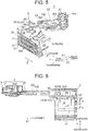
Fig.1 is a front view of a connector according to an embodiment of the present invention; -
Fig.2 is an exploded perspective view of the connector; -
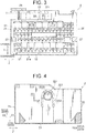
Fig.3 is a front view of a housing as a part of the connector; -
Fig.4 is a transverse sectional view along the line I-I inFig.3 ; -
Fig.5 is a perspective view for explaining a procedure for assembling the connector, - illustrating how a lever as a part of the connector is brought close to the housing;
-
Fig.6 is a longitudinal sectional view of the connector according toFig.5 ; -
Fig.7 is a longitudinal sectional view of a post process followingFig.6 , illustrating that the lever is pivotably supported by the housing and positioned in an initial position; -
Fig.8 is a longitudinal sectional view illustrating how insertion of an inner housing into the housing is limited; and -
Fig.9 is a longitudinal sectional view illustrating how the inner housing is allowed to be inserted into the housing, and when mating the connector with a partner connector, the lever is rotated to a completely rotated position. - Hereinafter, embodiments of the present invention will be described with reference to
Figs.1 to 9 .Fig.1 is a front view of a connector according to an embodiment of the present invention. - As shown in
Figs.1 ,2 and9 , aconnector 1 according to the present embodiment includes anouter housing 2, an inner housing 3 (shown inFig.2 ), a side spacer 4 (shown inFig.8 ), alever member 5 pivotably supported by theouter housing 2, and terminals (not shown), wherein theouter housing 2 corresponds to a housing according to claims. The terminals of theconnector 1 are connected to ends of electric wires (now shown), wherein in a state of thelever member 5 which is pivotably supported by theouter housing 2, the terminals of theconnector 1 are mated with terminals of a partner connector (not shown) by rotating thelever member 5. - According to the present embodiment, an inserting direction of the
inner housing 3 into theouter housing 2 shall be an X-direction, wherein two directions substantially orthogonal to the X-direction shall be a Y- and Z-direction. A rotation axis direction of thelever member 5 shall be the Y-direction. Further, an X1-direction (inserting direction of theinner housing 3 into the outer housing 2) and an X2-direction may be referred to as "forward" and "backward", respectively, wherein one direction along the Y-direction may referred to as "upward", while the other opposite direction along the Y-direction may be referred to as "downward". - As shown in
Fig.2 , theouter housing 2 is formed e.g. from a resin member in a quadrilateral-tubular shape having an extending direction (axial direction of the tube) along the X-direction. Thisouter housing 2 includes anouter wall section 21 along a ZY-plane, four outer surroundingwalls outer shell wall 26, wherein the outer surroundingwalls outer wall section 21, and theouter shell wall 26 is located above and opposed to the outer surroundingwall 22 along the ZX-plane (hereinafter referred to as "outerupper wall 22"). The outerupper wall 22 corresponds to "one wall section" according to claims, and theouter shell wall 26 corresponds to "another wall section" according to claims. Theouter wall section 21 hasterminal insertion holes 21a allowing tab terminals of a partner connector (not shown) to be inserted therethrough. Theterminal insertion holes 21a are provided in positions to be connected toterminal accommodating chambers 3A in theinner housing 3 which will be described below, wherein theterminal insertion holes 21a are configured to allow the tab terminals to enter theterminal accommodating chambers 3A. - As shown in
Fig.2 , theouter housing 2 further has alever mounting space 2A for mounting thelever member 5 therein, and a housing accommodatingspace 2B for accommodating theinner housing 3, wherein the housing accommodatingspace 2B corresponds to an insertion space according to claims. Thelever mounting space 2A and housing accommodatingspace 2B are defined by the outerupper wall 22. - The
lever mounting space 2A is provided between the outerupper wall 22 and theouter shell wall 26, as shown inFigs.2 and3 . At thelever mounting space 2A, a separation between the outerupper wall 22 and theouter shell wall 26 is formed with a substantially same dimension as a thickness of a levermain body 50 of thelever member 5 as described below. - As shown in
Fig.4 , the outerupper wall 22 includes alever rotating shaft 221 and aflexible arm 222, wherein thelever rotating shaft 221 corresponds to a rotation shaft section according to claims. Thelever rotating shaft 221 is provided in a middle portion of the outerupper wall 22 in the Z-direction. Thelever rotating shaft 221 is formed in a cylindrical shape and protrudes upward from the outerupper wall 22, wherein thelever rotating shaft 221 allowed to be inserted through ashaft bearing portion 501 of the levermain body 50 and pivotably supports the levermain body 50, wherein theshaft bearing portion 501 will be described below. - As shown in
Fig.4 , theflexible arm 222 is formed by a part of the outerupper wall 22, wherein aslit 223 is cut out in the outerupper wall 22 around thelever rotating shaft 221 so that theflexible arm 222 is bendable in the Y-direction. Theslit 223 includes a pair ofrectilinear slits shaped slit 223B, wherein the arc-shaped slit 223B is continuous between the pair ofrectilinear slits rectilinear slits lever rotating shaft 221 in the Z-direction and opposed to each other in the Z-direction, and extend in the X-direction (forward and backward direction). According to the present embodiment, the pair ofrectilinear slits upper wall 22. The arc-shaped slit 223B is provided in an arc shape which is continuous with back ends of therectilinear slits 223 and surrounds thelever rotating shaft 221. - As shown in
Figs.2 and5 , theouter shell wall 26 includes alock receiving portion 261 for locking atemporary lock arm 503 of the levermain body 50 therein, wherein thetemporary lock arm 261 will be described below. Thelock receiving portion 261 is disposed at a corner on a back side of the outer shell wall 26 (on a side in the X2-direciton) along a rotating direction of the lever main body 50 (clockwise as seen from above), wherein thelock receiving portion 261 is configured to lock thetemporary lock arm 503 of the levermain body 50 therein when the levermain body 50 has reached a completely rotated position, as shown inFig.2 , wherein the completely rotated position will be described below. - As shown in
Fig.2 , each of outer surroundingwalls walls guide portion 27, wherein theguide portion 27 extends in the X-direction. Each of theguide portions 27, together with aguide receiving portion 36 in theinner housing 3 as described below, forms aguide unit 6 for guiding a rib on the partner connector when mating theconnector 1 with the partner connector. - As shown in
Figs.2 and9 , theinner housing 3 includes aninner wall section 31 along the ZY-plane, four inner surroundingwalls terminal accommodating chambers 3A, and aspacer accommodating chamber 3B (shown inFig.8 ), wherein the inner surroundingwalls inner wall section 31. Further, an innerlower wall 33 of the four inner surroundingwalls wall 23 includes anopening 330 formed therein as shown inFig.8 , wherein theopening 330 is configured to insert aside spacer 4 therein. Surroundingwalls walls guide receiving portions 36 as shown inFig.2 , wherein theguide receiving portions 36, together with therespective guide portions 27 of theouter housing 2, form theguide units 6. - A plurality of
terminal accommodating chambers 3A are aligned in an up-down direction (Y-direction) and the Z-direction, as shown inFig.8 . Each of the terminalaccommodating chambers 3A has a quadrilateral-tubular shape with an extending direction (axial direction of the tube) along the X-direction, and is configured to accommodate the respective terminals. Thespacer accommodating chamber 3B is a part of the terminalaccommodating chambers 3A and capable of accommodating theside spacer 4. - As shown in
Fig.8 , theside spacer 4 is configured so as to be displaceable between a waiting position and an accommodating position, wherein in the waiting position, theside spacer 4 protrudes from the innerlower wall 33 while being inserted into theopening 330 in theinner housing 3, and in the accommodating position, theside spacer 4 has been pushed from the waiting position and accommodated in thespacer accommodating chamber 3B. When theside spacer 4 is in the waiting position, the terminals are allowed to be inserted into the terminalaccommodating chambers 3A, while when theside spacer 4 is in the accommodating position, theside spacer 4 causes the terminals inserted in the terminalaccommodating chambers 3A to be locked, whereby the terminals are held in the respectiveterminal accommodating chambers 3A. - As shown in
Figs.2 and5 , thelever member 5 includes the levermain body 50 and a slidingelement 51, wherein the levermain body 50 corresponds to a lever according to claims, wherein the slidingelement 51 is slidably supported by the levermain body 50. The levermain body 50 is formed e.g. from resin in a plate shape. The levermain body 50 extends along the ZX-plane (the same direction in which outerupper wall 22 andouter shell wall 26 extend). - As shown in
Fig.5 , the levermain body 50 includes theshaft bearing portion 501, aguide groove 502, thetemporary lock arm 503 for locking thelock receiving portion 261 in theouter housing 2, and aslide supporting portion 504 for supporting the slidingelement 51. Theshaft bearing portion 501 is formed in a through-hole shape, and configured to allow alever rotating shaft 221 of theouter housing 2 to be inserted through theshaft bearing portion 501. The levermain body 50 is configured to be (pivotably) supported so as to be rotatable relative to theouter housing 2 around theshaft bearing portion 501 and thelever rotating shaft 221 by inserting thelever rotating shaft 221 through theshaft bearing portion 501. - As shown in
Fig.5 , theguide groove 502 is defined by forming a part of an inner surface of the levermain body 50 in a concave shape, and is configured to allow a guide protrusion of the partner connector to be inserted through theguide groove 502. Theguide groove 502 is formed from a cam groove having a shape (trajectory) which brings the guide protrusion close to theshaft bearing portion 501 when the levermain body 50 is rotated. - With the lever
main body 50 as described above which is configured to be rotatable between an initial position (seeFig.7 ) and a completely rotated position (seeFig.9 ) while being pivotably supported by theouter housing 2, mating theconnector 1 with the partner connector is accomplished by rotating the levermain body 50 from the initial position to the completely rotated position. - The sliding
element 51 is supported by theslide supporting portion 504 so as to be slidable between a protruding position and a pushed-in position, wherein the sliding element protrudes backward (in the X2-direction) from the levermain body 50 in the protruding position, wherein the pushed-in position is located further forward (in the X1-direction) than the protruding position. Mating theconnector 1 with the partner connector is ensured by the slidingelement 51 which is slid from the protruding position to the pushed-in position when mating theconnector 1 with the partner connector. - Next, a procedure for assembling the
connector 1 will be described with reference toFigs.5 to 8 . First, theside spacer 4 is inserted into theopening 330 in theinner housing 3 in advance, and positioned in the waiting position, to accommodate the terminals into the respectiveterminal accommodating chambers 3A in theinner housing 3. Thereafter, theside spacer 4 is pushed in to be positioned in the accommodating position. In this manner, the terminals are held in the respectiveterminal accommodating chamber 3A. - Next, an insertion forward end 5S (a portion of the lever
main body 50 which is in the vicinity of an inlet of the guide groove 502) is brought close to and inserted into thelever mounting space 2A, as shown inFigs.5 and 6 . By further inserting the insertionforward end 5S of the levermain body 50, thelever rotating shaft 221 comes into contact with the insertionforward end 5S, wherein theflexible arm 222 is bent, and thelever rotating shaft 221 is removed out of thelever mounting space 2A (into the housingaccommodating space 2B) (seeFig.8 ). - By further inserting the insertion
forward end 5S of the levermain body 50, it crosses over thelever rotating shaft 221 so that thelever rotating shaft 221 is inserted through theshaft bearing portion 501 of the levermain body 50. Once thelever rotating shaft 221 has been inserted through theshaft bearing portion 501 of the levermain body 50, theflexible arm 222 is elastically returned to its original shape (natural state). In this manner, therotation shaft section 221 is rotatably supported by theshaft bearing portion 501, as shown inFig.7 , and the levermain body 50 is rotatably (pivotably) supported by theouter housing 2, wherein the levermain body 50 is positioned in the initial position. - Next, the
inner housing 3 is brought close to the housingaccommodating space 2B of theouter housing 2 and inserted into its front side (X1-direction). In this manner, theconnector 1 is assembled. - Here, an operator recognizes the absence of a fault in the assembly process when the
inner housing 3 is allowed to be inserted into the housingaccommodating space 2B. However, as shown inFig.8 , if thelever rotating shaft 221 is not inserted through theshaft bearing portion 501 of the levermain body 50 and theflexible arm 222 remains bent (incorrect condition), the insertion of theinner housing 3 into the housingaccommodating space 2B is limited by theinner housing 3 coming into contact with theflexible arm 222 due to theflexible arm 222 having entered the housingaccommodating space 2B. In this manner, the operator detects the incorrect condition (the presence of a fault in the assembly process) by the limitation of the insertion of theinner housing 3 into the housingaccommodating space 2B. - Further, e.g. in the case where the
inner housing 3 is brought close to the housingaccommodating space 2B of theouter housing 2 and inserted into its front side (X1-direction) while theside spacer 4 is positioned in the waiting position, the insertion of theinner housing 3 into the housingaccommodating space 2B is also limited by theside spacer 4 in contact with the outer surroundingwall 23 of theouter housing 2. In this manner, the operator can detect the presence of a fault in the assembly process by the limitation of the insertion of theinner housing 3 into the housingaccommodating space 2B. - Then, the
connector 1 will be mated with the partner connector by inserting the guide protrusion of the partner connector through theguide groove 502 of the connector 1 (shown inFig.5 ) and then by rotating the levermain body 50 to the completely rotated position as shown inFig.9 . - The embodiment as described above provides that the outer housing 2 (housing) includes the outer
upper wall 22 and the outer shell wall 26 (a pair of wall sections) opposed to each other in a rotation axis direction (arrow Y) of the lever main body 50 (lever), Wherein the outer upper wall 22 (one wall section) includes therotation shaft section 221 protruding towards the outer shell wall 26 (another wall section), wherein therotation shaft section 221 is provided in theflexible arm 222 which is cut out from the (outer upper wall 22), wherein it is configured so that in the natural state of theflexible arm 222, the levermain body 50 is pivotably supported by therotation shaft section 221, wherein when the levermain body 50 comes into contact with therotation shaft section 221, theflexible arm 222 is bent in a direction away from theouter shell wall 26 with interposition of the outer upper wall 22 (downward). With this configuration, when the levermain body 50 comes into contact with therotation shaft section 221, theflexible arm 222 is bent to displace therotation shaft section 221 downward, i.e. in the direction away from theouter shell wall 26 so that therotation shaft section 221 is removed outside the outerupper wall 22 and theouter shell wall 26. This enables the levermain body 50 to be inserted between the outerupper wall 22 and theouter shell wall 26 without bending thewalls connector 1 to be improved. - Further, in the natural state of the
flexible arm 222, theinner housing 3 is allowed to be inserted into the housingaccommodating space 2B (insertion space), wherein in a bent state of theflexible arm 222, theflexible arm 222 enters the housingaccommodating space 2B so that theinner housing 3 comes into contact with theflexible arm 222 to limit insertion of theinner housing 3 into the housing. With this configuration, it can be detected that the lever main body 50 (lever) is pivotably supported by therotation shaft section 221 of theouter housing 2, by the fact that theinner housing 3 is allowed to be inserted into the housingaccommodating space 2B. Moreover, by the fact that the insertion of theinner housing 3 into the housing is limited, the operator can detect that thelever rotating shaft 221 is not inserted into theshaft bearing portion 501 of the levermain body 50 and theflexible arm 222 remains bent (incorrect condition). - Although the best configuration, method etc. for implementing the present invention are disclosed in the above description, the present invention is not limited thereto. Namely, while the present invention is particularly shown and described mainly with regard to the specific embodiments, the above mentioned embodiments may be modified in various manners in shape, material characteristics, amount or other detailed features by those skilled in the art without departing from the scope of the technical idea and purpose of the present invention. Therefore, the description with limited shapes, material characteristics etc. according to the above disclosure is not limiting the present invention, but merely illustrative for easier understanding the present invention so that the description using names of the elements without a part or all of the limitations to their shapes, material characteristics etc. is also included in the present invention.
-
- 1
- Connector
- 2
- Outer housing (housing)
- 2B
- Housing accommodating space (insertion space)
- 3
- Inner housing
- 22
- Outer upper wall (one wall section)
- 26
- Outer shell wall (another wall section)
- 221
- Rotation shaft section (lever rotating shaft)
- 222
- Flexible arm
- 50
- Lever main body (lever)
- Arrow Y
- Up-down direction (rotation axis direction of the lever)
Claims (2)
- A connector comprising:a housing; anda plate-shaped lever which is pivotably supported by the housing and rotatable,wherein the housing includes a pair of wall sections opposed to each other in a rotation axis direction of the lever,wherein one wall section of the pair of wall sections includes a rotation shaft section protruding towards another wall section of the pair of wall sections,wherein the rotation shaft section is provided in a flexible arm which is cut out from the one wall section, andwherein it is configured so that in a natural state of the flexible arm, the lever is pivotably supported by the rotation shaft section, wherein when the lever which is not mounted is inserted between the pair of wall sections and comes into contact with the rotation shaft section, the flexible arm is bent in a direction away from the another wall section with interposition of the one wall section.
- The connector according to claim 1, further comprising:an inner housing configured to be inserted into the housing,wherein the housing has an insertion space for inserting the inner housing therein,wherein in the natural state of the flexible arm, the inner housing is allowed to be inserted into the housing, andwherein in a bent state of the flexible arm, the flexible arm enters the insertion space so that the inner housing comes into contact with the flexible arm to limit insertion of the inner housing into the housing.
Applications Claiming Priority (1)
| Application Number | Priority Date | Filing Date | Title |
|---|---|---|---|
| JP2020077518A JP2021174672A (en) | 2020-04-24 | 2020-04-24 | connector |
Publications (2)
| Publication Number | Publication Date |
|---|---|
| EP3905454A1 true EP3905454A1 (en) | 2021-11-03 |
| EP3905454B1 EP3905454B1 (en) | 2022-04-27 |
Family
ID=75659928
Family Applications (1)
| Application Number | Title | Priority Date | Filing Date |
|---|---|---|---|
| EP21170186.7A Active EP3905454B1 (en) | 2020-04-24 | 2021-04-23 | Electrical connector |
Country Status (4)
| Country | Link |
|---|---|
| US (1) | US20210336371A1 (en) |
| EP (1) | EP3905454B1 (en) |
| JP (1) | JP2021174672A (en) |
| CN (1) | CN113555729A (en) |
Families Citing this family (1)
| Publication number | Priority date | Publication date | Assignee | Title |
|---|---|---|---|---|
| JP7509822B2 (en) * | 2022-05-12 | 2024-07-02 | 矢崎総業株式会社 | Connector housings, connectors, and wire harnesses |
Citations (2)
| Publication number | Priority date | Publication date | Assignee | Title |
|---|---|---|---|---|
| EP1990870A1 (en) * | 2005-09-29 | 2008-11-12 | Sumitomo Wiring Systems, Ltd. | A connector and connector assembly |
| JP2015079657A (en) | 2013-10-17 | 2015-04-23 | 矢崎総業株式会社 | Lever type connector |
Family Cites Families (2)
| Publication number | Priority date | Publication date | Assignee | Title |
|---|---|---|---|---|
| JP2003249303A (en) * | 2002-02-26 | 2003-09-05 | Sumitomo Wiring Syst Ltd | Lever type connector |
| JP2013089385A (en) * | 2011-10-14 | 2013-05-13 | Yazaki Corp | Lever type connector |
-
2020
- 2020-04-24 JP JP2020077518A patent/JP2021174672A/en not_active Abandoned
-
2021
- 2021-04-14 US US17/230,185 patent/US20210336371A1/en not_active Abandoned
- 2021-04-21 CN CN202110431745.3A patent/CN113555729A/en not_active Withdrawn
- 2021-04-23 EP EP21170186.7A patent/EP3905454B1/en active Active
Patent Citations (2)
| Publication number | Priority date | Publication date | Assignee | Title |
|---|---|---|---|---|
| EP1990870A1 (en) * | 2005-09-29 | 2008-11-12 | Sumitomo Wiring Systems, Ltd. | A connector and connector assembly |
| JP2015079657A (en) | 2013-10-17 | 2015-04-23 | 矢崎総業株式会社 | Lever type connector |
Also Published As
| Publication number | Publication date |
|---|---|
| CN113555729A (en) | 2021-10-26 |
| US20210336371A1 (en) | 2021-10-28 |
| JP2021174672A (en) | 2021-11-01 |
| EP3905454B1 (en) | 2022-04-27 |
Similar Documents
| Publication | Publication Date | Title |
|---|---|---|
| CN103262356B (en) | Lever-type connector and wire cover | |
| EP1962390B1 (en) | A connector and a connector assembly | |
| US20100041266A1 (en) | Power connector with integrated signal connector | |
| CN110943332A (en) | Electrical connector for circuit boards and method for producing the electrical connector for circuit boards | |
| WO2014054672A1 (en) | Terminal and terminal manufacturing method | |
| KR20060048214A (en) | Multicore Optical Connector Assembly | |
| US20220393383A1 (en) | Terminal position assurance device and corresponding connector assembly | |
| JP2011501359A (en) | Electrical connector assembly | |
| US12046848B2 (en) | Connector having a housing and a mounting member | |
| US7131858B1 (en) | Angled coaxial cable connector for mating axis termination method | |
| EP3905454B1 (en) | Electrical connector | |
| JP4190019B2 (en) | connector | |
| US11437757B2 (en) | Connector unit | |
| CN119137817A (en) | Connectors | |
| WO2021079587A1 (en) | Joint connector | |
| CN110911873B (en) | connection terminal | |
| US20260135331A1 (en) | Connector unit | |
| CN224067942U (en) | Connector assembly | |
| US10892582B2 (en) | Connector with upper and lower covers | |
| US12614865B2 (en) | Plug connector and insulating housing for a plug connector | |
| US11990700B2 (en) | Connector with front mask | |
| JP7831721B2 (en) | Connectors, connection assemblies, and connection groups | |
| JP2002184511A (en) | connector | |
| JP7436315B2 (en) | connector | |
| CN120637930A (en) | Terminal block and method for installing the terminal block |
Legal Events
| Date | Code | Title | Description |
|---|---|---|---|
| PUAI | Public reference made under article 153(3) epc to a published international application that has entered the european phase |
Free format text: ORIGINAL CODE: 0009012 |
|
| STAA | Information on the status of an ep patent application or granted ep patent |
Free format text: STATUS: REQUEST FOR EXAMINATION WAS MADE |
|
| 17P | Request for examination filed |
Effective date: 20210423 |
|
| AK | Designated contracting states |
Kind code of ref document: A1 Designated state(s): AL AT BE BG CH CY CZ DE DK EE ES FI FR GB GR HR HU IE IS IT LI LT LU LV MC MK MT NL NO PL PT RO RS SE SI SK SM TR |
|
| B565 | Issuance of search results under rule 164(2) epc |
Effective date: 20211001 |
|
| RBV | Designated contracting states (corrected) |
Designated state(s): AL AT BE BG CH CY CZ DE DK EE ES FI FR GB GR HR HU IE IS IT LI LT LU LV MC MK MT NL NO PL PT RO RS SE SI SK SM TR |
|
| RIC1 | Information provided on ipc code assigned before grant |
Ipc: H01R 13/436 20060101ALN20220105BHEP Ipc: H01R 13/641 20060101ALI20220105BHEP Ipc: H01R 13/629 20060101AFI20220105BHEP |
|
| GRAP | Despatch of communication of intention to grant a patent |
Free format text: ORIGINAL CODE: EPIDOSNIGR1 |
|
| STAA | Information on the status of an ep patent application or granted ep patent |
Free format text: STATUS: GRANT OF PATENT IS INTENDED |
|
| RIC1 | Information provided on ipc code assigned before grant |
Ipc: H01R 13/436 20060101ALN20220117BHEP Ipc: H01R 13/641 20060101ALI20220117BHEP Ipc: H01R 13/629 20060101AFI20220117BHEP |
|
| RIC1 | Information provided on ipc code assigned before grant |
Ipc: H01R 13/436 20060101ALN20220201BHEP Ipc: H01R 13/641 20060101ALI20220201BHEP Ipc: H01R 13/629 20060101AFI20220201BHEP |
|
| INTG | Intention to grant announced |
Effective date: 20220214 |
|
| GRAS | Grant fee paid |
Free format text: ORIGINAL CODE: EPIDOSNIGR3 |
|
| GRAA | (expected) grant |
Free format text: ORIGINAL CODE: 0009210 |
|
| STAA | Information on the status of an ep patent application or granted ep patent |
Free format text: STATUS: THE PATENT HAS BEEN GRANTED |
|
| AK | Designated contracting states |
Kind code of ref document: B1 Designated state(s): AL AT BE BG CH CY CZ DE DK EE ES FI FR GB GR HR HU IE IS IT LI LT LU LV MC MK MT NL NO PL PT RO RS SE SI SK SM TR |
|
| REG | Reference to a national code |
Ref country code: GB Ref legal event code: FG4D |
|
| REG | Reference to a national code |
Ref country code: CH Ref legal event code: EP |
|
| REG | Reference to a national code |
Ref country code: DE Ref legal event code: R096 Ref document number: 602021000075 Country of ref document: DE |
|
| REG | Reference to a national code |
Ref country code: AT Ref legal event code: REF Ref document number: 1487694 Country of ref document: AT Kind code of ref document: T Effective date: 20220515 |
|
| REG | Reference to a national code |
Ref country code: IE Ref legal event code: FG4D |
|
| REG | Reference to a national code |
Ref country code: LT Ref legal event code: MG9D |
|
| REG | Reference to a national code |
Ref country code: NL Ref legal event code: MP Effective date: 20220427 |
|
| REG | Reference to a national code |
Ref country code: AT Ref legal event code: MK05 Ref document number: 1487694 Country of ref document: AT Kind code of ref document: T Effective date: 20220427 |
|
| PG25 | Lapsed in a contracting state [announced via postgrant information from national office to epo] |
Ref country code: NL Free format text: LAPSE BECAUSE OF FAILURE TO SUBMIT A TRANSLATION OF THE DESCRIPTION OR TO PAY THE FEE WITHIN THE PRESCRIBED TIME-LIMIT Effective date: 20220427 |
|
| PG25 | Lapsed in a contracting state [announced via postgrant information from national office to epo] |
Ref country code: SE Free format text: LAPSE BECAUSE OF FAILURE TO SUBMIT A TRANSLATION OF THE DESCRIPTION OR TO PAY THE FEE WITHIN THE PRESCRIBED TIME-LIMIT Effective date: 20220427 Ref country code: PT Free format text: LAPSE BECAUSE OF FAILURE TO SUBMIT A TRANSLATION OF THE DESCRIPTION OR TO PAY THE FEE WITHIN THE PRESCRIBED TIME-LIMIT Effective date: 20220829 Ref country code: NO Free format text: LAPSE BECAUSE OF FAILURE TO SUBMIT A TRANSLATION OF THE DESCRIPTION OR TO PAY THE FEE WITHIN THE PRESCRIBED TIME-LIMIT Effective date: 20220727 Ref country code: LT Free format text: LAPSE BECAUSE OF FAILURE TO SUBMIT A TRANSLATION OF THE DESCRIPTION OR TO PAY THE FEE WITHIN THE PRESCRIBED TIME-LIMIT Effective date: 20220427 Ref country code: HR Free format text: LAPSE BECAUSE OF FAILURE TO SUBMIT A TRANSLATION OF THE DESCRIPTION OR TO PAY THE FEE WITHIN THE PRESCRIBED TIME-LIMIT Effective date: 20220427 Ref country code: GR Free format text: LAPSE BECAUSE OF FAILURE TO SUBMIT A TRANSLATION OF THE DESCRIPTION OR TO PAY THE FEE WITHIN THE PRESCRIBED TIME-LIMIT Effective date: 20220728 Ref country code: FI Free format text: LAPSE BECAUSE OF FAILURE TO SUBMIT A TRANSLATION OF THE DESCRIPTION OR TO PAY THE FEE WITHIN THE PRESCRIBED TIME-LIMIT Effective date: 20220427 Ref country code: BG Free format text: LAPSE BECAUSE OF FAILURE TO SUBMIT A TRANSLATION OF THE DESCRIPTION OR TO PAY THE FEE WITHIN THE PRESCRIBED TIME-LIMIT Effective date: 20220727 Ref country code: AT Free format text: LAPSE BECAUSE OF FAILURE TO SUBMIT A TRANSLATION OF THE DESCRIPTION OR TO PAY THE FEE WITHIN THE PRESCRIBED TIME-LIMIT Effective date: 20220427 |
|
| PG25 | Lapsed in a contracting state [announced via postgrant information from national office to epo] |
Ref country code: RS Free format text: LAPSE BECAUSE OF FAILURE TO SUBMIT A TRANSLATION OF THE DESCRIPTION OR TO PAY THE FEE WITHIN THE PRESCRIBED TIME-LIMIT Effective date: 20220427 Ref country code: PL Free format text: LAPSE BECAUSE OF FAILURE TO SUBMIT A TRANSLATION OF THE DESCRIPTION OR TO PAY THE FEE WITHIN THE PRESCRIBED TIME-LIMIT Effective date: 20220427 Ref country code: LV Free format text: LAPSE BECAUSE OF FAILURE TO SUBMIT A TRANSLATION OF THE DESCRIPTION OR TO PAY THE FEE WITHIN THE PRESCRIBED TIME-LIMIT Effective date: 20220427 Ref country code: IS Free format text: LAPSE BECAUSE OF FAILURE TO SUBMIT A TRANSLATION OF THE DESCRIPTION OR TO PAY THE FEE WITHIN THE PRESCRIBED TIME-LIMIT Effective date: 20220827 |
|
| REG | Reference to a national code |
Ref country code: DE Ref legal event code: R097 Ref document number: 602021000075 Country of ref document: DE |
|
| PG25 | Lapsed in a contracting state [announced via postgrant information from national office to epo] |
Ref country code: SM Free format text: LAPSE BECAUSE OF FAILURE TO SUBMIT A TRANSLATION OF THE DESCRIPTION OR TO PAY THE FEE WITHIN THE PRESCRIBED TIME-LIMIT Effective date: 20220427 Ref country code: SK Free format text: LAPSE BECAUSE OF FAILURE TO SUBMIT A TRANSLATION OF THE DESCRIPTION OR TO PAY THE FEE WITHIN THE PRESCRIBED TIME-LIMIT Effective date: 20220427 Ref country code: RO Free format text: LAPSE BECAUSE OF FAILURE TO SUBMIT A TRANSLATION OF THE DESCRIPTION OR TO PAY THE FEE WITHIN THE PRESCRIBED TIME-LIMIT Effective date: 20220427 Ref country code: ES Free format text: LAPSE BECAUSE OF FAILURE TO SUBMIT A TRANSLATION OF THE DESCRIPTION OR TO PAY THE FEE WITHIN THE PRESCRIBED TIME-LIMIT Effective date: 20220427 Ref country code: EE Free format text: LAPSE BECAUSE OF FAILURE TO SUBMIT A TRANSLATION OF THE DESCRIPTION OR TO PAY THE FEE WITHIN THE PRESCRIBED TIME-LIMIT Effective date: 20220427 Ref country code: DK Free format text: LAPSE BECAUSE OF FAILURE TO SUBMIT A TRANSLATION OF THE DESCRIPTION OR TO PAY THE FEE WITHIN THE PRESCRIBED TIME-LIMIT Effective date: 20220427 Ref country code: CZ Free format text: LAPSE BECAUSE OF FAILURE TO SUBMIT A TRANSLATION OF THE DESCRIPTION OR TO PAY THE FEE WITHIN THE PRESCRIBED TIME-LIMIT Effective date: 20220427 |
|
| PLBE | No opposition filed within time limit |
Free format text: ORIGINAL CODE: 0009261 |
|
| STAA | Information on the status of an ep patent application or granted ep patent |
Free format text: STATUS: NO OPPOSITION FILED WITHIN TIME LIMIT |
|
| PG25 | Lapsed in a contracting state [announced via postgrant information from national office to epo] |
Ref country code: AL Free format text: LAPSE BECAUSE OF FAILURE TO SUBMIT A TRANSLATION OF THE DESCRIPTION OR TO PAY THE FEE WITHIN THE PRESCRIBED TIME-LIMIT Effective date: 20220427 |
|
| 26N | No opposition filed |
Effective date: 20230130 |
|
| PGFP | Annual fee paid to national office [announced via postgrant information from national office to epo] |
Ref country code: DE Payment date: 20230228 Year of fee payment: 3 |
|
| PG25 | Lapsed in a contracting state [announced via postgrant information from national office to epo] |
Ref country code: LU Free format text: LAPSE BECAUSE OF NON-PAYMENT OF DUE FEES Effective date: 20230423 |
|
| REG | Reference to a national code |
Ref country code: BE Ref legal event code: MM Effective date: 20230430 |
|
| PG25 | Lapsed in a contracting state [announced via postgrant information from national office to epo] |
Ref country code: MC Free format text: LAPSE BECAUSE OF FAILURE TO SUBMIT A TRANSLATION OF THE DESCRIPTION OR TO PAY THE FEE WITHIN THE PRESCRIBED TIME-LIMIT Effective date: 20220427 |
|
| PG25 | Lapsed in a contracting state [announced via postgrant information from national office to epo] |
Ref country code: MC Free format text: LAPSE BECAUSE OF FAILURE TO SUBMIT A TRANSLATION OF THE DESCRIPTION OR TO PAY THE FEE WITHIN THE PRESCRIBED TIME-LIMIT Effective date: 20220427 Ref country code: IT Free format text: LAPSE BECAUSE OF FAILURE TO SUBMIT A TRANSLATION OF THE DESCRIPTION OR TO PAY THE FEE WITHIN THE PRESCRIBED TIME-LIMIT Effective date: 20220427 Ref country code: FR Free format text: LAPSE BECAUSE OF NON-PAYMENT OF DUE FEES Effective date: 20230430 |
|
| REG | Reference to a national code |
Ref country code: IE Ref legal event code: MM4A |
|
| PG25 | Lapsed in a contracting state [announced via postgrant information from national office to epo] |
Ref country code: BE Free format text: LAPSE BECAUSE OF NON-PAYMENT OF DUE FEES Effective date: 20230430 |
|
| PG25 | Lapsed in a contracting state [announced via postgrant information from national office to epo] |
Ref country code: IE Free format text: LAPSE BECAUSE OF NON-PAYMENT OF DUE FEES Effective date: 20230423 |
|
| PG25 | Lapsed in a contracting state [announced via postgrant information from national office to epo] |
Ref country code: IE Free format text: LAPSE BECAUSE OF NON-PAYMENT OF DUE FEES Effective date: 20230423 |
|
| REG | Reference to a national code |
Ref country code: DE Ref legal event code: R119 Ref document number: 602021000075 Country of ref document: DE |
|
| PG25 | Lapsed in a contracting state [announced via postgrant information from national office to epo] |
Ref country code: BG Free format text: LAPSE BECAUSE OF FAILURE TO SUBMIT A TRANSLATION OF THE DESCRIPTION OR TO PAY THE FEE WITHIN THE PRESCRIBED TIME-LIMIT Effective date: 20220427 |
|
| PG25 | Lapsed in a contracting state [announced via postgrant information from national office to epo] |
Ref country code: BG Free format text: LAPSE BECAUSE OF FAILURE TO SUBMIT A TRANSLATION OF THE DESCRIPTION OR TO PAY THE FEE WITHIN THE PRESCRIBED TIME-LIMIT Effective date: 20220427 |
|
| REG | Reference to a national code |
Ref country code: CH Ref legal event code: PL |
|
| PG25 | Lapsed in a contracting state [announced via postgrant information from national office to epo] |
Ref country code: DE Free format text: LAPSE BECAUSE OF NON-PAYMENT OF DUE FEES Effective date: 20241105 |
|
| PG25 | Lapsed in a contracting state [announced via postgrant information from national office to epo] |
Ref country code: DE Free format text: LAPSE BECAUSE OF NON-PAYMENT OF DUE FEES Effective date: 20241105 Ref country code: CH Free format text: LAPSE BECAUSE OF NON-PAYMENT OF DUE FEES Effective date: 20240430 |
|
| PG25 | Lapsed in a contracting state [announced via postgrant information from national office to epo] |
Ref country code: CY Free format text: LAPSE BECAUSE OF FAILURE TO SUBMIT A TRANSLATION OF THE DESCRIPTION OR TO PAY THE FEE WITHIN THE PRESCRIBED TIME-LIMIT; INVALID AB INITIO Effective date: 20210423 |
|
| PG25 | Lapsed in a contracting state [announced via postgrant information from national office to epo] |
Ref country code: HU Free format text: LAPSE BECAUSE OF FAILURE TO SUBMIT A TRANSLATION OF THE DESCRIPTION OR TO PAY THE FEE WITHIN THE PRESCRIBED TIME-LIMIT; INVALID AB INITIO Effective date: 20210423 |
|
| PG25 | Lapsed in a contracting state [announced via postgrant information from national office to epo] |
Ref country code: TR Free format text: LAPSE BECAUSE OF FAILURE TO SUBMIT A TRANSLATION OF THE DESCRIPTION OR TO PAY THE FEE WITHIN THE PRESCRIBED TIME-LIMIT Effective date: 20220427 |
|
| GBPC | Gb: european patent ceased through non-payment of renewal fee |
Effective date: 20250423 |
|
| PG25 | Lapsed in a contracting state [announced via postgrant information from national office to epo] |
Ref country code: GB Free format text: LAPSE BECAUSE OF NON-PAYMENT OF DUE FEES Effective date: 20250423 |
|
| PG25 | Lapsed in a contracting state [announced via postgrant information from national office to epo] |
Ref country code: SI Free format text: LAPSE BECAUSE OF FAILURE TO SUBMIT A TRANSLATION OF THE DESCRIPTION OR TO PAY THE FEE WITHIN THE PRESCRIBED TIME-LIMIT Effective date: 20220427 |