EP3905423A1 - Standby power supply device and method for charging secondary battery - Google Patents
Standby power supply device and method for charging secondary battery Download PDFInfo
- Publication number
- EP3905423A1 EP3905423A1 EP19902139.5A EP19902139A EP3905423A1 EP 3905423 A1 EP3905423 A1 EP 3905423A1 EP 19902139 A EP19902139 A EP 19902139A EP 3905423 A1 EP3905423 A1 EP 3905423A1
- Authority
- EP
- European Patent Office
- Prior art keywords
- secondary batteries
- power supply
- charge voltage
- secondary battery
- deterioration
- Prior art date
- Legal status (The legal status is an assumption and is not a legal conclusion. Google has not performed a legal analysis and makes no representation as to the accuracy of the status listed.)
- Withdrawn
Links
Images




Classifications
-
- H—ELECTRICITY
- H02—GENERATION; CONVERSION OR DISTRIBUTION OF ELECTRIC POWER
- H02J—ELECTRIC POWER NETWORKS; CIRCUIT ARRANGEMENTS OR SYSTEMS FOR SUPPLYING OR DISTRIBUTING ELECTRIC POWER; SYSTEMS FOR STORING ELECTRIC ENERGY
- H02J9/00—Circuit arrangements for emergency or stand-by power supply, e.g. for emergency lighting
- H02J9/04—Circuit arrangements for emergency or stand-by power supply, e.g. for emergency lighting in which the distribution system is disconnected from the normal source and connected to a standby source
- H02J9/06—Circuit arrangements for emergency or stand-by power supply, e.g. for emergency lighting in which the distribution system is disconnected from the normal source and connected to a standby source with automatic change-over, e.g. UPS systems
- H02J9/061—Circuit arrangements for emergency or stand-by power supply, e.g. for emergency lighting in which the distribution system is disconnected from the normal source and connected to a standby source with automatic change-over, e.g. UPS systems for DC powered loads
-
- H—ELECTRICITY
- H02—GENERATION; CONVERSION OR DISTRIBUTION OF ELECTRIC POWER
- H02J—ELECTRIC POWER NETWORKS; CIRCUIT ARRANGEMENTS OR SYSTEMS FOR SUPPLYING OR DISTRIBUTING ELECTRIC POWER; SYSTEMS FOR STORING ELECTRIC ENERGY
- H02J7/00—Circuit arrangements for charging or discharging batteries or for supplying loads from batteries
- H02J7/80—Circuit arrangements for charging or discharging batteries or for supplying loads from batteries including monitoring or indicating arrangements
- H02J7/84—Control of state of health [SOH]
-
- H—ELECTRICITY
- H01—ELECTRIC ELEMENTS
- H01M—PROCESSES OR MEANS, e.g. BATTERIES, FOR THE DIRECT CONVERSION OF CHEMICAL ENERGY INTO ELECTRICAL ENERGY
- H01M10/00—Secondary cells; Manufacture thereof
- H01M10/42—Methods or arrangements for servicing or maintenance of secondary cells or secondary half-cells
- H01M10/44—Methods for charging or discharging
-
- H—ELECTRICITY
- H01—ELECTRIC ELEMENTS
- H01M—PROCESSES OR MEANS, e.g. BATTERIES, FOR THE DIRECT CONVERSION OF CHEMICAL ENERGY INTO ELECTRICAL ENERGY
- H01M10/00—Secondary cells; Manufacture thereof
- H01M10/42—Methods or arrangements for servicing or maintenance of secondary cells or secondary half-cells
- H01M10/48—Accumulators combined with arrangements for measuring, testing or indicating the condition of cells, e.g. the level or density of the electrolyte
-
- H—ELECTRICITY
- H02—GENERATION; CONVERSION OR DISTRIBUTION OF ELECTRIC POWER
- H02J—ELECTRIC POWER NETWORKS; CIRCUIT ARRANGEMENTS OR SYSTEMS FOR SUPPLYING OR DISTRIBUTING ELECTRIC POWER; SYSTEMS FOR STORING ELECTRIC ENERGY
- H02J7/00—Circuit arrangements for charging or discharging batteries or for supplying loads from batteries
- H02J7/90—Regulation of charging or discharging current or voltage
- H02J7/96—Regulation of charging or discharging current or voltage in response to battery voltage
-
- H—ELECTRICITY
- H02—GENERATION; CONVERSION OR DISTRIBUTION OF ELECTRIC POWER
- H02J—ELECTRIC POWER NETWORKS; CIRCUIT ARRANGEMENTS OR SYSTEMS FOR SUPPLYING OR DISTRIBUTING ELECTRIC POWER; SYSTEMS FOR STORING ELECTRIC ENERGY
- H02J7/00—Circuit arrangements for charging or discharging batteries or for supplying loads from batteries
- H02J7/90—Regulation of charging or discharging current or voltage
- H02J7/971—Regulation of charging or discharging current or voltage the charge cycle being controlled or terminated in response to non-electric parameters
-
- H—ELECTRICITY
- H02—GENERATION; CONVERSION OR DISTRIBUTION OF ELECTRIC POWER
- H02J—ELECTRIC POWER NETWORKS; CIRCUIT ARRANGEMENTS OR SYSTEMS FOR SUPPLYING OR DISTRIBUTING ELECTRIC POWER; SYSTEMS FOR STORING ELECTRIC ENERGY
- H02J2105/00—Networks for supplying or distributing electric power characterised by their spatial reach or by the load
- H02J2105/40—Networks for supplying or distributing electric power characterised by their spatial reach or by the load characterised by the loads connecting to the networks or being supplied by the networks
- H02J2105/42—Home appliances
- H02J2105/425—Home appliances the loads being an Information and Communication Technology [ICT] facility
-
- Y—GENERAL TAGGING OF NEW TECHNOLOGICAL DEVELOPMENTS; GENERAL TAGGING OF CROSS-SECTIONAL TECHNOLOGIES SPANNING OVER SEVERAL SECTIONS OF THE IPC; TECHNICAL SUBJECTS COVERED BY FORMER USPC CROSS-REFERENCE ART COLLECTIONS [XRACs] AND DIGESTS
- Y02—TECHNOLOGIES OR APPLICATIONS FOR MITIGATION OR ADAPTATION AGAINST CLIMATE CHANGE
- Y02E—REDUCTION OF GREENHOUSE GAS [GHG] EMISSIONS, RELATED TO ENERGY GENERATION, TRANSMISSION OR DISTRIBUTION
- Y02E60/00—Enabling technologies; Technologies with a potential or indirect contribution to GHG emissions mitigation
- Y02E60/10—Energy storage using batteries
Definitions
- the present invention relates to a standby power supply device used as an uninterruptible power supply or an emergency power supply, and a method for charging a secondary battery included in the standby power supply device.
- a power supply device including a secondary battery is used as a backup power supply at the time of a power failure or an emergency in a server or a data center.
- a conventional power supply device has a structure in which a built-in secondary battery is on standby in a fully charged state in order to unfailingly supply power to a system and protect data and the like at the time of instantaneous power interruption due to power failure or the like. Thus, deterioration of the secondary battery that is held in a fully charged state for a long time is likely to be promoted.
- the secondary battery used in this type of power supply device needs to be replaced after a lapse of a certain period due to aged deterioration.
- the period until replacement of the secondary battery is also shortened, and thus, it is desired to extend the life of the secondary battery. In order to extend the life, it is conceivable to reduce a load on the secondary battery.
- An object of the present invention is to provide a standby power supply device capable of suppressing a load applied to a secondary battery and extending a battery life, and a method for charging a secondary battery.
- the standby power supply device having the above configuration is characterized in that the load applied to the secondary batteries is suppressed and the battery life can be extended.
- the charging circuit of the standby power supply device described above includes a voltage adjuster that controls the state of charge of the secondary batteries and a controller that controls the voltage adjuster by detecting the degree of deterioration of the secondary batteries over time, and the voltage adjuster charges the secondary batteries at charge voltage Vc lower than full charge voltage Vf of the secondary batteries to bring the secondary batteries into a load power supply standby state, and gradually increases charge voltage Vc of the secondary batteries according to the degree of deterioration of the secondary batteries detected by the controller.
- the standby power supply device described above can reduce the load applied to the secondary batteries by charging the secondary batteries at charge voltage Vc lower than the full charge voltage, instead of charging to fully charge the secondary batteries at full charge voltage Vf at the beginning of use. Moreover, since the degree of deterioration of the secondary batteries is detected and charge voltage Vc is gradually increased according to the degree of deterioration of the secondary batteries, it is possible to prevent a reduction in charging capacity over time and to extend the battery life while securing the charging capacity requested for the standby power supply device.
- Controller 4 of charging circuit 2 can detect the degree of deterioration of secondary batteries 1 from SOH of secondary batteries 1.
- a standby power supply device includes one or more secondary batteries 1 and charging circuit 2 that charges secondary batteries 1.
- Charging circuit 2 includes voltage adjuster 3 that controls the state of charge of secondary batteries 1, and controller 4 that controls voltage adjuster 3 by detecting a discharge standby time of secondary batteries 1.
- controller 4 voltage adjuster 3 charges secondary batteries 1 at charge voltage Vc lower than full charge voltage Vf of secondary batteries 1 to bring secondary batteries 1 into a load power supply standby state, and gradually increases charge voltage Vc of secondary batteries 1 according to the discharge standby time of secondary batteries 1 detected by controller 4.
- the standby power supply device having the above configuration is characterized in that the load applied to the secondary batteries is suppressed and the battery life can be extended.
- the charging circuit of the standby power supply device described above includes a voltage adjuster that controls the state of charge of the secondary batteries and a controller that controls the voltage adjuster by detecting the discharge standby time of the secondary batteries, and the voltage adjuster charges the secondary batteries at charge voltage Vc lower than full charge voltage Vf of the secondary batteries to bring the secondary batteries into a load power supply standby state, and gradually increases charge voltage Vc of the secondary batteries according to the discharge standby time of the secondary batteries detected by the controller.
- the standby power supply device described above can reduce the load applied to the secondary batteries by charging the secondary batteries at charge voltage Vc lower than full charge voltage Vf, instead of charging to fully charge the secondary batteries at full charge voltage Vf at the beginning of use. Moreover, since charge voltage Vc is gradually increased according to the discharge standby time of the secondary batteries, it is possible to prevent a reduction in charging capacity over time and to extend the battery life while securing the charging capacity requested for the standby power supply device.
- charging circuit 2 can charge secondary batteries 1 with a power amount exceeding a load request power amount requested by a load connected to the standby power supply device to bring secondary batteries 1 into a load power supply standby state.
- the load request power amount means a power amount requested for the standby power supply device as a minimum power amount necessary for driving the load connected to the standby power supply device for a predetermined time at the time of a power failure or an emergency.
- the secondary batteries are charged with the power amount necessary for driving the load connected to the standby power supply device for the predetermined time to be in the load power supply standby state, and therefore the load can be unfailingly driven by supplying the power necessary for the load for the predetermined time at the time of a power failure or an emergency, and the system, data, and the like of the load can be unfailingly protected.
- a method for charging a secondary battery according to an aspect of the present invention is a method for charging secondary batteries 1 included in standby power supply device 100, the method including: detecting the degree of deterioration of secondary batteries 1 over time; and gradually increasing charge voltage Vc of secondary batteries 1 according to the detected degree of deterioration within a range lower than full charge voltage Vf of secondary batteries 1.
- charge voltage Vc is gradually increased according to the degree of deterioration of the secondary batteries within a range lower than full charge voltage Vf, it is possible to prevent a reduction in charging capacity over time and to extend the battery life while securing the charging capacity requested for the standby power supply device.
- the method for charging a secondary battery can detect the degree of deterioration of secondary batteries 1 from SOH of secondary batteries 1.
- a method for charging a secondary battery according to another aspect of the present invention is a method for charging secondary batteries 1 included in standby power supply device 100, the method including: detecting the discharge standby time of secondary batteries 1; and gradually increasing charge voltage Vc of secondary batteries 1 according to the detected discharge standby time within a range lower than full charge voltage Vf of secondary batteries 1.
- the method for charging a secondary battery described above is characterized in that the load applied to the secondary batteries is suppressed and the battery life can be extended. This is because the charging method described above detects the discharge standby time of the secondary batteries; and gradually increases charge voltage Vc of the secondary batteries according to the detected discharge standby time within a range lower than full charge voltage Vf of the secondary batteries.
- the charging method described above can reduce the load applied to the secondary batteries by charging the secondary batteries at charge voltage Vc lower than full charge voltage Vf, instead of charging the secondary batteries at full charge voltage Vf at the beginning of use.
- charge voltage Vc is gradually increased according to the discharge standby time of the secondary batteries within a range lower than full charge voltage Vf, it is possible to prevent a reduction in charging capacity over time and to extend the battery life while securing the charging capacity requested for the standby power supply device.
- the load can be unfailingly driven by supplying the power necessary for the load for the predetermined time at the time of a power failure or an emergency, and the system, data, and the like of the load can be unfailingly protected.
- FIG. 1 is a block diagram showing standby power supply device 100 according to an exemplary embodiment of the present invention.
- Standby power supply device 100 includes rectifier circuit 8, charging circuit 2, and battery unit 9 to which one or more secondary batteries 1 are connected.
- Charging circuit 2 includes voltage adjuster 3 that controls the state of charge of secondary batteries 1, and controller 4 that controls voltage adjuster 3.
- Voltage adjuster 3 is a member for controlling the state of charge of secondary batteries 1.
- Controller 4 is a member for controlling voltage adjuster 3 by detecting the degree of deterioration of secondary batteries 1 over time.
- This voltage adjuster 3 is configured to charge secondary batteries 1 at charge voltage Vc lower than full charge voltage Vf of these secondary batteries 1 to bring secondary batteries 1 into a load power supply standby state, and gradually increase charge voltage Vc of secondary batteries 1 according to the degree of deterioration of secondary batteries 1 detected by controller 4.
- standby power supply device 100 Commercial power supply 30 is connected to the input, and load 20 to which the power is supplied is connected to the output.
- Main power supply 40 is connected to an input of load 20 to which standby power supply device 100 is connected, and in a normal state, drive power is supplied from main power supply 40 to drive load 20.
- An output of standby power supply device 100 is connected in parallel to an output of main power supply 40, and when the drive power is not supplied from main power supply 40 due to a power failure or the like, the power is promptly supplied from standby power supply device 100 to load 20.
- the load to be used includes, for example, a device that is requested to be supplied with power for a predetermined time in a state where the supply power is interrupted such as a power failure.
- a device that is requested to be supplied with power for a predetermined time in a state where the supply power is interrupted such as a power failure.
- load 20 connected to standby power supply device 100 typically, a server, a data center, an electronic device such as a computer or a hard disk, or the like is used.
- These loads 20 are devices having an extremely large adverse effect caused by interruption of the operating power supplied from main power supply 40 due to a power failure, an instantaneous power interruption in which a power failure instantaneously occurs, or the like.
- drive power for normally executing an operation such as executing a backup operation or switching to a reserve power supply is required for a predetermined time. Therefore, standby power supply device 100 supplies a load request power amount requested for load 20 as a minimum power amount necessary for driving load 20 connected to standby power supply device 100 for a predetermined time at the time of a power failure or an emergency.
- controller 4 detects the degree of deterioration of secondary batteries 1 over time or detects the discharge standby time of secondary batteries 1, and controls voltage adjuster 3 to gradually increase charge voltage Vc of secondary batteries 1 according to the degree of deterioration or the discharge standby time of secondary batteries 1 detected by controller 4.
- Controller 4 in FIG. 1 detects the degree of deterioration of secondary batteries 1 over time using deterioration degree detector 5.
- the degree of deterioration of secondary batteries 1 detected by controller 4 can be detected from, for example, a state of health (SOH) of secondary batteries 1.
- Controller 4 calculates the degree of deterioration of secondary batteries 1, and charges by changing charge voltage Vc of secondary batteries 1 to second charge voltage V2 higher than first charge voltage V1 according to the deterioration amount. Thus, deterioration of secondary batteries 1 can be suppressed, and the expected life in a high-temperature environment can be improved.
- the charging method of the standby power supply device may further include a step of calculating the degree of deterioration of secondary batteries 1 with controller 4 and charging by changing the charge voltage of secondary batteries 1 to third charge voltage V3 higher than second charge voltage V2 according to the deterioration amount.
- the degree of deterioration of secondary batteries 1 can be typically deterioration capacity SOH of secondary batteries 1.
- controller 4 may change charge voltage Vc of secondary batteries 1 to second charge voltage V2 higher than first charge voltage V1.
- controller 4 may change the charge voltage of secondary batteries 1 to second charge voltage V2 higher than first charge voltage V1.
- the method of detecting the degree of deterioration of secondary batteries 1 over time and increasing the charge voltage based on the value has been described above.
- the present invention is not limited to this method, and the deterioration of the secondary batteries may be predicted in advance without detecting the degree of deterioration of the secondary batteries, and the charge voltage may be changed according to the lapse of time.
- Charging circuit 2 detects the degree of deterioration of secondary batteries 1 over time and gradually increases charge voltage Vc of secondary batteries 1 according to the detected degree of deterioration within a range lower than full charge voltage Vf of secondary batteries 1. That is, at the beginning of use of secondary batteries 1, charging circuit 2 charges charge voltage Vc of secondary batteries 1 at first charge voltage V1 lower than full charge voltage Vf of secondary batteries 1. At this time, secondary batteries 1 are not fully charged, but are charged with a predetermined capacity that can supply a larger power amount than the request power amount requested for the load. Standby power supply device 100 charges with a power amount of 100 Wh, for example, so as to be able to supply power of 180 seconds with power of 2000 W.
- charging circuit 2 determines charge voltage Vc so as to be able to charge with a power amount greater than 100 Wh.
- a plurality of secondary batteries 1 is connected in multiple series and multiple parallel to form battery unit 9 in order to supply a predetermined amount of power amount.
- Microcontroller 7 controls voltage adjuster 3 to charge secondary batteries 1 at predetermined charge voltage Vc lower than full charge voltage Vf. Secondary batteries 1 are charged at charge voltage Vc lower than full charge voltage Vf, so that secondary batteries 1 are charged to a charge amount that can be charged at charge voltage Vc without being fully charged.
- Controller 4 controls voltage adjuster 3 to charge secondary batteries 1 at predetermined charge voltage Vc.
- controller 4 detects the voltage and the remaining capacity of secondary batteries 1 and detects that the voltage and the remaining capacity of secondary batteries 1 decrease to a charge start value
- microcontroller 7 switches voltage adjuster 3 to the charging state to charge secondary batteries 1.
- microcontroller 7 detects this state and controls voltage adjuster 3 to stop charging secondary batteries 1.
- Secondary batteries 1 are non-aqueous electrolyte secondary batteries, and for example, a lithium ion battery is used.
- Standby power supply device 100 shown in the drawing includes a plurality of secondary batteries 1 and the plurality of secondary batteries 1 is connected in multiple parallel and multiple series to form battery unit 9 so that a predetermined power amount can be supplied to load 20 in an emergency.
- Standby power supply device 100 can adjust the charge and discharge capacity by the number of secondary batteries 1 connected as battery unit 9. Therefore, standby power supply device 100 includes a number of secondary batteries 1 having the optimum capacity for the intended use.
- standby power supply device 100 in which secondary batteries 1 are lithium ion batteries for example, when 52 secondary batteries 1 are connected in 4 parallel and 13 series as battery unit 9, the output voltage can be increased and the current capacity can be increased.
- Secondary batteries 1 are set to a capacity capable of outputting, for example, power of 400 W to 3 kW to a power supply line of load 20, e.g., a server, continuously for two minutes to ten minutes.
- Standby power supply device 100 adjusts the number of secondary batteries 1 connected in series and in parallel so that power of, for example, 2.0 kW can be continuously supplied to load 20 for 180 seconds to several minutes.
- standby power supply device 100 shown in FIG. 1 includes rectifier circuit 8 that converts commercial power supply 30 to be input, for example, an alternating current having a frequency of 50 Hz or 60 Hz and a voltage of 100 V or 200 V into a direct current.
- Rectifier circuit 8 is connected to charging circuit 2.
- Charging circuit 2 includes voltage adjuster 3 that controls the state of charge of secondary batteries 1, and controller 4 that controls voltage adjuster 3. Charging circuit 2 detects the remaining capacity of secondary batteries 1 based on the voltage output from voltage adjuster 3, starts charging when the remaining capacity becomes smaller than a setting capacity, and then, when secondary batteries 1 are charged with an electric capacity exceeding the load request power amount, detects this and stops charging.
- charging circuit 2 detects the degree of deterioration of secondary batteries 1 over time, adjusts charge voltage Vc for charging secondary batteries 1 according to the detected degree of deterioration or detects the discharge standby time of secondary batteries 1, and adjusts charge voltage Vc for charging secondary batteries 1 according to the detected discharge standby time or adjusts charge voltage Vc according to both the degree of deterioration and the discharge standby time.
- Voltage adjuster 3 converts the direct current output from rectifier circuit 8 into a direct current having a predetermined voltage and charges secondary batteries 1.
- a DC/DC converter can be used as voltage adjuster 3.
- the DC/DC converter includes, in addition to a switching element that is a transistor or an FET that switches direct current input from rectifier circuit 8, a control circuit that switches on and off of the switching element at a frequency higher than a commercial power supply, for example, a frequency higher than 100 kHz, a high-frequency transformer that is connected on a primary side to the switching element, a rectifier circuit that is connected to the secondary side of the high-frequency transformer, and the like.
- the output from secondary batteries 1 is supplied to load 20 via output line 16 in a state where the power supply from commercial power supply 30 is stopped, such as a power failure.
- the power supply is switched to the power supply from secondary batteries 1 at the same time as the power supply is stopped, so that adverse effects such as instantaneous power interruption can be unfailingly prevented.
- diode 17 that prevents backflow is connected to output line 16 on the output of secondary batteries 1.
- an output switch may be provided in the output line from the secondary batteries, and power may be supplied from the secondary batteries to the load by switching the output switch to an ON state at the time of a power failure.
- the standby power supply device includes a power failure detection circuit that detects a power failure state, and when the power failure detection circuit detects a power failure, the output switch is switched on to supply power from the secondary batteries to the load.
- Standby power supply device 100 of the present invention performs the operation described below to supply power to load 20.
- standby power supply device 100 stands by as the load power supply standby state in a state where secondary batteries 1 are charged with a predetermined 9 power amount.
- voltage adjuster 3 holds secondary batteries 1 in a state of being charged at predetermined charge voltage Vc.
- standby power supply device 100 With standby power supply device 100, deterioration of secondary batteries 1 can be suppressed by charging with only a necessary discharge power capacity.
- a conventional backup power supply is operated with the charge voltage of the secondary batteries being fixed to full charge voltage Vf (for example, 4.0 V/cell).
- Vf for example, 4.0 V/cell.
- the charge voltage is set to charge voltage Vc lower than full charge voltage Vf according to the deterioration of secondary batteries 1.
- initial charge voltage Vc is intentionally set low to such an extent that the requested discharge power of the load can be satisfied. Then, when initial charge voltage Vc cannot satisfy the request due to capacity deterioration, charge voltage Vc is increased.
- charge voltage Vc which is one of the main factors promoting the capacity deterioration of secondary batteries 1, can be kept low, and the life can be extended. Further, with the realization of the long life, in a case where the life is the same as the conventional life, it is possible to cope with a higher temperature environment than the conventional case.
- the graph of FIG. 2 shows a relationship between a discharge capacity and an open circuit voltage of secondary batteries 1.
- a discharge curve of the secondary batteries shows a discharge characteristic as shown by curve A in the drawing. That is, as the discharge progresses and the discharge capacity increases, the open circuit voltage of the secondary batteries decreases. Further, as the secondary batteries deteriorate, the chargeable capacity decreases. Curve B and curve C in the drawing simply show an image in which the electric capacity of the secondary batteries decreases as the deterioration progresses.
- curve B indicates a curve of a discharge characteristic at the initial stage of use
- curve C indicates a curve of a discharge characteristic in a state where deterioration has progressed.
- hatched areas correspond to the load request power amount requested by the load connected to the standby power supply device, and correspond to the necessary power amount required per cell.
- the secondary batteries can be charged with a requested necessary power amount without necessarily being charged at a high charge voltage.
- the necessary power amount can be charged while the charge voltage is set to first charge voltage V1 lower than full charge voltage Vf.
- the charge voltage is set to second charge voltage V2 higher than first charge voltage V1, which is the initial charge voltage, so that the necessary power amount can be charged.
- the charge voltage is initially set high, and the charge voltage is lowered as the battery deteriorates.
- the charge voltage is lowered as the battery deteriorates.
- the secondary batteries is maintained in a fully charged state, deterioration is occurred due to heat generation, and the capacity tends to decrease due to the progress of deterioration.
- the charging method since the capacity of secondary batteries 1 is large in the initial state where there is little deterioration, the charge voltage is suppressed to be lower than full charge voltage Vf. For example, as indicated in curve B, the necessary power amount is charged by setting the charge voltage to V1. On the other hand, since the capacity decreases as the deterioration progresses, the charge voltage is made higher than V1 to secure the necessary power amount. For example, as indicated in curve C, the necessary power is secured by setting the charge voltage to V2. As described above, contrary to the conventional method, by increasing the charge voltage according to the deterioration, an excellent effect of extending the battery life is obtained.
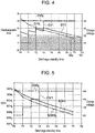
- FIG. 4 shows a state in which dischargeable time DT1, DT0 1 (left vertical axis) of the secondary batteries at certain temperature TP1 becomes shorter with the lapse of the discharge standby time (horizontal axis) and a state in which charge voltage CV1, CV0 1 (right vertical axis) is changed with the lapse of the discharge standby time (horizontal axis) regarding the charging methods according to Example 1 and Comparative Example 1. Further, the dischargeable time (necessary power amount) required per cell is indicated by hatching corresponding to the load request power amount requested by the load connected to standby power supply device 100.
- FIG. 4 shows a state in which dischargeable time DT1, DT0 1 (left vertical axis) of the secondary batteries at certain temperature TP1 becomes shorter with the lapse of the discharge standby time (horizontal axis) and a state in which charge voltage CV1, CV0 1 (right vertical axis) is changed with the lapse of the discharge standby time (horizontal axis) regarding the charging methods according to Example
- charge voltage CV1 is changed according to deterioration rate SOH of the secondary batteries as indicated by the curve in the drawing. Since deterioration rate SOH decreases with time, the charge voltage increases with time. For example, in the period from lapsed time T0 to T1 at the left end of FIG. 4 , charge voltage CV1 is considerably smaller than charge voltage CV0 1 of the charging method according to Comparative Example 1. As a result, since the capacity charged in the secondary batteries is smaller than the capacity in Comparative Example 1, dischargeable time DT1 according to Example 1 is also smaller than dischargeable time DT0 1 of Comparative Example 1. However, since the necessary capacity indicated by hatching is not reached, it is possible to supply necessary power to the load.
- the standby power supply device also deteriorates with time, and dischargeable time DT1 also shows a downward gradient. Therefore, before dischargeable time DT1 reaches the necessary capacity, charge voltage CV1 is increased to increase dischargeable time DT1.
- deterioration degree SOH of secondary batteries 1 is detected by controller 4, and before reaching the necessary capacity, preferably when reaching a lower limit value obtained by adding a margin to the necessary capacity, voltage adjuster 3 is controlled to increase charge voltage CV1.
- charge voltage CV1 is increased to increase dischargeable time CV1 at the time point of reaching lapsed time T1.
- the same control is repeated to increase charge voltage CV1 according to deterioration degree SOH of the secondary batteries.
- dischargeable time DT1 becomes shorter with time, that is, DT1 decreases, the decrease can be suppressed by increasing charge voltage CV1.
- charge voltage CV1 of the secondary batteries is suppressed to be low, so that deterioration can be suppressed and the life can be extended.
- dischargeable time DT1 of Example 1 exceeds dischargeable time DT0 1 of Comparative Example 1 at lapsed time T3, and the lapse of time to finally reach the necessary capacity can be extended to TD1.
- FIG. 5 shows a state in which deterioration degree SOH1, SOH0 1 (left vertical axis) of the secondary batteries at the same temperature TP1 as in FIG. 4 decreases with the lapse of the discharge standby time (horizontal axis) and a state in which charge voltage CV1, CV0 1 (right vertical axis) is changed with the lapse of the discharge standby time (horizontal axis) regarding the charging methods according to Example 1 and Comparative Example 1.
- FIG. 6 shows a state in which dischargeable time DT2, DT0 2 (left vertical axis) of the secondary batteries at temperature TP2 becomes shorter with the lapse of the discharge standby time (horizontal axis) and a state in which charge voltage CV2, CV0 2 (right vertical axis) is changed with the lapse of the discharge standby time (horizontal axis) regarding the charging methods according to Example 2 and Comparative Example 2. Similar to FIG. 6
- the dischargeable time of the secondary batteries according to Example 2 is denoted by DT2
- the dischargeable time of the secondary batteries according to Comparative Example 2 is denoted by DT0 2
- the charge voltage of the secondary batteries according to Example 2 is denoted by CV2
- the charge voltage according to Comparative Example 2 is denoted by CV0 2
- the requested dischargeable time is indicated by hatching.
- the charge voltage is also fixed at CV0 2 regardless of the discharge standby time. As a result, when the lapse of time reaches TD0 2 , the necessary capacity cannot be supplied, and the life is reached.
- charge voltage CV2 is increased according to deterioration rate SOH of the secondary batteries as indicated by the curve in the drawing.
- charge voltage CV2 is considerably smaller than charge voltage CV0 2 of the charging method according to Comparative Example 2.
- dischargeable time DT2 according to Example 2 is also smaller than dischargeable time DT0 2 of Comparative Example 2.
- the necessary capacity indicated by hatching is not reached, it is possible to supply necessary power to the load.
- the standby power supply device also deteriorates with time, and dischargeable time DT2 also shows a downward gradient. Therefore, before dischargeable time DT2 reaches the necessary capacity, charge voltage CV2 is increased to increase dischargeable time DT2.
- charge voltage CV2 is increased to increase dischargeable time DT2 at the time point of reaching lapsed time T1.
- the same control is repeated to increase charge voltage CV2 according to deterioration degree SOH of the secondary batteries.
- dischargeable time DT2 becomes shorter with time, that is, DT2 decreases, the decrease can be suppressed by increasing charge voltage CV2.
- dischargeable time DT2 of Example 2 exceeds dischargeable time DT0 2 of Comparative Example 2 at lapsed time T3, and the lapse of time to finally reach the necessary capacity can be extended to TD2.
- FIG. 7 shows a state in which deterioration degree SOH2, SOH0 2 (left vertical axis) of the secondary batteries at the same temperature TP2 as in FIG. 6 decreases with the lapse of the discharge standby time (horizontal axis) and a state in which charge voltage CV2, CV0 2 (right vertical axis) is changed with the lapse of the discharge standby time (horizontal axis) regarding the charging methods according to Example 2 and Comparative Example 2.
- FIGS. 8 shows a state in which dischargeable time DT2, DT0 1 (left vertical axis) of the secondary batteries becomes shorter with the lapse of the discharge standby time (horizontal axis) and a state in which charge voltage CV2, CV0 1 (right vertical axis) is changed with the lapse of the discharge standby time (horizontal axis) regarding the charging method according to Example 2 at temperature TP2 and the charging method according to Comparative Example 1 at temperature TP1. Similar to FIGS.
- the dischargeable time of the secondary batteries according to Example 2 is denoted by DT2
- the dischargeable time of the secondary batteries according to Comparative Example 1 is denoted by DT0 1
- the charge voltage of the secondary batteries according to Example 2 is denoted by CV2
- the charge voltage according to Comparative Example 1 is denoted by CV0 1
- the requested dischargeable time is indicated by hatching.
- FIG. 9 shows a state in which deterioration degree SOH2, SOH0 1 (left vertical axis) of the secondary batteries decreases with the lapse of the discharge standby time (horizontal axis) and a state in which charge voltage CV2, CV0 1 (right vertical axis) is changed with the lapse of the discharge standby time (horizontal axis) regarding the charging method according to Example 2 at temperature TP2 and the charging method according to Comparative Example 1 at temperature TP1.
- deterioration degree SOH2 of the secondary batteries according to Example 2 in a higher temperature environment is suppressed to about the same degree as deterioration degree SOH0 1 of the secondary batteries by the charging method of Comparative Example 1 at a low temperature.
- the high heat resistance has been obtained from the viewpoint of the degree of deterioration by the charging method according to the exemplary embodiment.
- the method of detecting the degree of deterioration of secondary batteries 1 with controller 4 and controlling voltage adjuster 3 to increase the charge voltage is adopted.
- the reference for changing the charge voltage is not limited to the degree of deterioration of the secondary batteries.
- parameters such as SOC, battery temperature, charge and discharge current, and temperature may be used. These are parameters used when the degree of deterioration of the battery is calculated, and in other words, even when the degree of deterioration of the battery is not calculated on the basis of these parameters, the same result can be obtained by controlling using the value of each parameter or a combination thereof.
- the present invention includes not only an aspect in which the degree of deterioration of the battery is calculated as a numerical value or control is performed on the basis of the degree of deterioration, but also an aspect in which it is determined that the timing at which the charge voltage is changed, here, increased, is reached at the time point when a predetermined combination is reached substantially on the basis of a table, a simulation result, or the like calculated and determined in advance from parameters such as the temperature, the current, and the voltage of the battery.
- the predicted deterioration of secondary batteries 1 is associated with the change in charge voltage in advance, and the timing at which the charge voltage is changed from the start of use of secondary batteries 1 is set as the discharge standby time, and is held in controller 4 as a table or data. Further, the discharge standby time may be set in units of secondary battery cells, or may be set for the entire battery unit in which a plurality of secondary battery cells is combined. Then, controller 4 detects the discharge standby time of secondary batteries 1 and controls voltage adjuster 3. The lapse of time from the start of use of secondary batteries 1 can be detected by timer 6 or the like.
- voltage adjuster 3 charges secondary batteries 1 at charge voltage Vc lower than full charge voltage Vf of secondary batteries 1 to bring secondary batteries 1 into a load power supply standby state, and gradually increases charge voltage Vc of secondary batteries 1 according to the discharge standby time of secondary batteries 1 detected by controller 4.
- the charge voltage is suppressed to suppress heat generation, and the life can be extended while power supply to the load is guaranteed.
- charging circuit 2 charges secondary batteries 1 with a power amount exceeding the load request power amount requested by the load connected to standby power supply device 100 to bring secondary batteries 1 into the load power supply standby state.
- the degree of deterioration may be obtained from remaining capacity state of charge (SOC) of the secondary batteries.
- SOC is obtained from, for example, an equation described below.
- SOC Cr / Cf ⁇ 100 (Cr: remaining capacity [Ah]; Cf: full charging capacity [Ah])
- the secondary batteries are discharged from a fully charged state to a predetermined level. For example, the discharge is performed until depth of discharge (DOD) reaches a predetermined value. Then, after waiting until open circuit voltage OCV of the secondary batteries is stabilized, SOH is calculated from voltage difference ⁇ OCV before and after discharge.
- DOD depth of discharge
- OCV-SOC does not depend on deterioration
- ⁇ OCV is converted into ⁇ SOC.
- FCC [Wh] is calculated from ⁇ SOC and discharged capacity Q[Wh] using an equation described below.
- FCC Q * 100 / ⁇ SOC
- charging circuit 2 of standby power supply device 100 shown in FIG. 1 includes discharging circuit 11 for discharging secondary batteries 1 after secondary batteries 1 are fully charged.
- Discharging circuit 11 shown in FIG. 1 includes a series circuit of current adjustment resistor 12 and switch 13, and is connected in parallel to battery unit 9.
- Deterioration degree detector 5 of controller 4 calculates discharged capacity Q[Wh] from the discharge current and the discharge time of secondary batteries 1 in a state where switch 13 of discharging circuit 11 is controlled to be turned on.
- deterioration degree detector 5 calculates SOH from ⁇ SOC obtained from difference ⁇ OCV of the open circuit voltage of secondary batteries 1. As described above, deterioration degree detector 5 of controller 4 detects deterioration degree SOH of secondary batteries 1 at a predetermined cycle as time elapses.
- the standby power supply device and the method for charging a secondary battery of the present invention can be appropriately used for applications including a backup power supply device for a data center, wireless base stations of, for example, cellular phones, a power storage device combined with a solar battery, such as a power storage power source for homes and factories or a power source for street lights, and a backup power source for traffic lights.
Landscapes
- Engineering & Computer Science (AREA)
- Power Engineering (AREA)
- General Chemical & Material Sciences (AREA)
- Chemical & Material Sciences (AREA)
- Chemical Kinetics & Catalysis (AREA)
- Electrochemistry (AREA)
- Manufacturing & Machinery (AREA)
- Business, Economics & Management (AREA)
- Emergency Management (AREA)
- Charge And Discharge Circuits For Batteries Or The Like (AREA)
- Health & Medical Sciences (AREA)
- General Health & Medical Sciences (AREA)
- Medical Informatics (AREA)
- Secondary Cells (AREA)
Abstract
Description
- The present invention relates to a standby power supply device used as an uninterruptible power supply or an emergency power supply, and a method for charging a secondary battery included in the standby power supply device.
- A power supply device including a secondary battery is used as a backup power supply at the time of a power failure or an emergency in a server or a data center. A conventional power supply device has a structure in which a built-in secondary battery is on standby in a fully charged state in order to unfailingly supply power to a system and protect data and the like at the time of instantaneous power interruption due to power failure or the like. Thus, deterioration of the secondary battery that is held in a fully charged state for a long time is likely to be promoted.
- For this reason, the secondary battery used in this type of power supply device needs to be replaced after a lapse of a certain period due to aged deterioration. Thus, when the secondary battery to be replaced deteriorates quickly, the period until replacement of the secondary battery is also shortened, and thus, it is desired to extend the life of the secondary battery. In order to extend the life, it is conceivable to reduce a load on the secondary battery.
- On the other hand, an increase in output of the power supply device is also demanded. For example, in a backup power supply device, it is demanded to maintain high output discharge for a predetermined time, and the load on the secondary battery tends to increase. When the charge current increases, the heat generation of the secondary battery also increases, and the deterioration becomes severe, which affects the life.
-
- PTL 1: Unexamined
Japanese Patent Publication No. 2013-247003 - PTL 2: Unexamined
Japanese Patent Publication No. 2008-252960 - PTL 3: Unexamined
Japanese Patent Publication No. 2008-228492 - An object of the present invention is to provide a standby power supply device capable of suppressing a load applied to a secondary battery and extending a battery life, and a method for charging a secondary battery. Solution to problem and advantageous effect of invention
- A standby power supply device according to an aspect of the present invention includes one or more
secondary batteries 1 andcharging circuit 2 that chargessecondary batteries 1.Charging circuit 2 includesvoltage adjuster 3 that controls the state of charge ofsecondary batteries 1, andcontroller 4 that controls voltage adjuster 3 by detecting the degree of deterioration ofsecondary batteries 1 over time. Incharging circuit 2, voltage adjuster 3 chargessecondary batteries 1 at charge voltage Vc lower than full charge voltage Vf ofsecondary batteries 1 to bringsecondary batteries 1 into a load power supply standby state, and gradually increases charge voltage Vc ofsecondary batteries 1 according to the degree of deterioration ofsecondary batteries 1 detected bycontroller 4. - The standby power supply device having the above configuration is characterized in that the load applied to the secondary batteries is suppressed and the battery life can be extended. This is because the charging circuit of the standby power supply device described above includes a voltage adjuster that controls the state of charge of the secondary batteries and a controller that controls the voltage adjuster by detecting the degree of deterioration of the secondary batteries over time, and the voltage adjuster charges the secondary batteries at charge voltage Vc lower than full charge voltage Vf of the secondary batteries to bring the secondary batteries into a load power supply standby state, and gradually increases charge voltage Vc of the secondary batteries according to the degree of deterioration of the secondary batteries detected by the controller. The standby power supply device described above can reduce the load applied to the secondary batteries by charging the secondary batteries at charge voltage Vc lower than the full charge voltage, instead of charging to fully charge the secondary batteries at full charge voltage Vf at the beginning of use. Moreover, since the degree of deterioration of the secondary batteries is detected and charge voltage Vc is gradually increased according to the degree of deterioration of the secondary batteries, it is possible to prevent a reduction in charging capacity over time and to extend the battery life while securing the charging capacity requested for the standby power supply device.
-
Controller 4 ofcharging circuit 2 can detect the degree of deterioration ofsecondary batteries 1 from SOH ofsecondary batteries 1. - A standby power supply device according to another aspect of the present invention includes one or more
secondary batteries 1 andcharging circuit 2 that chargessecondary batteries 1.Charging circuit 2 includesvoltage adjuster 3 that controls the state of charge ofsecondary batteries 1, andcontroller 4 that controls voltage adjuster 3 by detecting a discharge standby time ofsecondary batteries 1. Incontroller 4,voltage adjuster 3 chargessecondary batteries 1 at charge voltage Vc lower than full charge voltage Vf ofsecondary batteries 1 to bringsecondary batteries 1 into a load power supply standby state, and gradually increases charge voltage Vc ofsecondary batteries 1 according to the discharge standby time ofsecondary batteries 1 detected bycontroller 4. - The standby power supply device having the above configuration is characterized in that the load applied to the secondary batteries is suppressed and the battery life can be extended. This is because the charging circuit of the standby power supply device described above includes a voltage adjuster that controls the state of charge of the secondary batteries and a controller that controls the voltage adjuster by detecting the discharge standby time of the secondary batteries, and the voltage adjuster charges the secondary batteries at charge voltage Vc lower than full charge voltage Vf of the secondary batteries to bring the secondary batteries into a load power supply standby state, and gradually increases charge voltage Vc of the secondary batteries according to the discharge standby time of the secondary batteries detected by the controller. The standby power supply device described above can reduce the load applied to the secondary batteries by charging the secondary batteries at charge voltage Vc lower than full charge voltage Vf, instead of charging to fully charge the secondary batteries at full charge voltage Vf at the beginning of use. Moreover, since charge voltage Vc is gradually increased according to the discharge standby time of the secondary batteries, it is possible to prevent a reduction in charging capacity over time and to extend the battery life while securing the charging capacity requested for the standby power supply device.
- Moreover, in the standby power supply device of the present invention,
charging circuit 2 can chargesecondary batteries 1 with a power amount exceeding a load request power amount requested by a load connected to the standby power supply device to bringsecondary batteries 1 into a load power supply standby state. - In the present specification, the load request power amount means a power amount requested for the standby power supply device as a minimum power amount necessary for driving the load connected to the standby power supply device for a predetermined time at the time of a power failure or an emergency.
- With the above configuration, since the secondary batteries are charged with the power amount necessary for driving the load connected to the standby power supply device for the predetermined time to be in the load power supply standby state, and therefore the load can be unfailingly driven by supplying the power necessary for the load for the predetermined time at the time of a power failure or an emergency, and the system, data, and the like of the load can be unfailingly protected.
- A method for charging a secondary battery according to an aspect of the present invention is a method for charging
secondary batteries 1 included in standbypower supply device 100, the method including: detecting the degree of deterioration ofsecondary batteries 1 over time; and gradually increasing charge voltage Vc ofsecondary batteries 1 according to the detected degree of deterioration within a range lower than full charge voltage Vf ofsecondary batteries 1. - The method for charging a secondary battery described above is characterized in that the load applied to the secondary batteries is suppressed and the battery life can be extended. This is because the charging method described above detects the degree of deterioration of the secondary batteries over time; and gradually increases charge voltage Vc of the secondary batteries according to the detected degree of deterioration within a range lower than full charge voltage Vf of the secondary batteries. The charging method described above can reduce the load applied to the secondary batteries by charging the secondary batteries at charge voltage Vc lower than full charge voltage Vf, instead of charging the secondary batteries at full charge voltage Vf at the beginning of use. Moreover, since charge voltage Vc is gradually increased according to the degree of deterioration of the secondary batteries within a range lower than full charge voltage Vf, it is possible to prevent a reduction in charging capacity over time and to extend the battery life while securing the charging capacity requested for the standby power supply device.
- Moreover, the method for charging a secondary battery can detect the degree of deterioration of
secondary batteries 1 from SOH ofsecondary batteries 1. - A method for charging a secondary battery according to another aspect of the present invention is a method for charging
secondary batteries 1 included in standbypower supply device 100, the method including: detecting the discharge standby time ofsecondary batteries 1; and gradually increasing charge voltage Vc ofsecondary batteries 1 according to the detected discharge standby time within a range lower than full charge voltage Vf ofsecondary batteries 1. - The method for charging a secondary battery described above is characterized in that the load applied to the secondary batteries is suppressed and the battery life can be extended. This is because the charging method described above detects the discharge standby time of the secondary batteries; and gradually increases charge voltage Vc of the secondary batteries according to the detected discharge standby time within a range lower than full charge voltage Vf of the secondary batteries. The charging method described above can reduce the load applied to the secondary batteries by charging the secondary batteries at charge voltage Vc lower than full charge voltage Vf, instead of charging the secondary batteries at full charge voltage Vf at the beginning of use. Moreover, since charge voltage Vc is gradually increased according to the discharge standby time of the secondary batteries within a range lower than full charge voltage Vf, it is possible to prevent a reduction in charging capacity over time and to extend the battery life while securing the charging capacity requested for the standby power supply device.
- Moreover, the method for charging a secondary battery can charge
secondary batteries 1 with a power amount exceeding a load request power amount requested by a load to which power is supplied fromsecondary batteries 1 to bringsecondary batteries 1 into a load power supply standby state. - According to the above method, since the secondary batteries are charged with the power amount necessary for driving the load to which the power is supplied from the secondary batteries for the predetermined time to be in the load power supply standby state, and therefore the load can be unfailingly driven by supplying the power necessary for the load for the predetermined time at the time of a power failure or an emergency, and the system, data, and the like of the load can be unfailingly protected.
-
-
FIG. 1 is a schematic block diagram of a standby power supply device according to an exemplary embodiment of the present invention. -
FIG. 2 is a graph showing a relationship between a discharge capacity and a voltage of a secondary battery. -
FIG. 3 is a graph showing a state in which a deterioration rate of a secondary battery decreases with time. -
FIG. 4 is a graph showing changes in dischargeable time and charge voltage with respect to discharge standby time of a secondary battery at temperature TP1 regarding charging methods according to Example 1 and Comparative Example 1. -
FIG. 5 is a graph showing changes in degree of deterioration and charge voltage with respect to discharge standby time of a secondary battery at temperature TP1 regarding charging methods according to Example 1 and Comparative Example 1. -
FIG. 6 is a graph showing changes in dischargeable time and charge voltage with respect to discharge standby time of a secondary battery at temperature TP2 regarding charging methods according to Example 2 and Comparative Example 2. -
FIG. 7 is a graph showing changes in degree of deterioration and charge voltage with respect to discharge standby time of a secondary battery at temperature TP2 regarding charging methods according to Example 2 and Comparative Example 2. -
FIG. 8 is a graph showing changes in dischargeable time and charge voltage with respect to discharge standby time of a secondary battery regarding a charging method according to Example 2 at temperature TP2 and a charging method according to Comparative Example 1 at temperature TP1. -
FIG. 9 is a graph showing changes in degree of deterioration and charge voltage with respect to discharge standby time of a secondary battery regarding a charging method according to Example 2 at temperature TP2 and a charging method according to Comparative Example 1 at temperature TP1. -
FIG. 10 is a graph showing an example of a method for estimating SOH. - Hereinafter, exemplary embodiments of the present invention will be described on the basis of the drawings. However, exemplary embodiments described below are an example for embodying the technical idea of the present invention, and the present invention is not limited to the following. Further, in the present specification, members indicated in the claims are not limited to the members of the exemplary embodiments. In particular, the dimensions, materials, shapes, and the relative arrangements of the components described in the exemplary embodiments are not intended to limit the scope of the present invention thereto unless otherwise specified, and are merely illustrative examples. The sizes and positional relationships of members shown in the drawings may be exaggerated for clarity of description. Further, in the following description, the same names and reference numerals indicate the same or similar members, and detailed description will be appropriately omitted. Moreover, each element constituting the present invention may be configured such that a plurality of elements is configured by the same member and one member also serves as a plurality of elements, or conversely, the function of one member can be shared and achieved by a plurality of members.
-
FIG. 1 is a block diagram showing standbypower supply device 100 according to an exemplary embodiment of the present invention. Standbypower supply device 100 includes rectifier circuit 8, chargingcircuit 2, and battery unit 9 to which one or moresecondary batteries 1 are connected.Charging circuit 2 includesvoltage adjuster 3 that controls the state of charge ofsecondary batteries 1, andcontroller 4 that controlsvoltage adjuster 3.Voltage adjuster 3 is a member for controlling the state of charge ofsecondary batteries 1.Controller 4 is a member for controllingvoltage adjuster 3 by detecting the degree of deterioration ofsecondary batteries 1 over time. Thisvoltage adjuster 3 is configured to chargesecondary batteries 1 at charge voltage Vc lower than full charge voltage Vf of thesesecondary batteries 1 to bringsecondary batteries 1 into a load power supply standby state, and gradually increase charge voltage Vc ofsecondary batteries 1 according to the degree of deterioration ofsecondary batteries 1 detected bycontroller 4. - In standby
power supply device 100,commercial power supply 30 is connected to the input, and load 20 to which the power is supplied is connected to the output.Main power supply 40 is connected to an input ofload 20 to which standbypower supply device 100 is connected, and in a normal state, drive power is supplied frommain power supply 40 to driveload 20. An output of standbypower supply device 100 is connected in parallel to an output ofmain power supply 40, and when the drive power is not supplied frommain power supply 40 due to a power failure or the like, the power is promptly supplied from standbypower supply device 100 to load 20. - The load to be used includes, for example, a device that is requested to be supplied with power for a predetermined time in a state where the supply power is interrupted such as a power failure. As an example, there is a server, a computer, or the like that requires time to back up data or terminate the system when the supply power is interrupted. Alternatively, it is also used in an aspect in which it is not preferable that the supply power is interrupted during reading or writing of data. In this case, time for storing data or shutting down the system is required. Therefore, in a state where the supply power is interrupted, power supply for securing a time required for such work is required. In other words, it is only required that a standby power supply device is charged with such a power amount that a request power amount can be supplied. Alternatively, it is sufficient if a power supply of another system such as a private power generator or another high-capacity backup power supply is prepared and necessary power can be supplied until the power supply is switched to such a power supply of another system within a predetermined time after a power failure is detected. As described above, the standby power supply device is not necessarily required to have a high capacity, and it is sufficient if the standby power supply device can normally store data or shut down, or supply power until the power supply is switched to the power supply of another system (for example, about several minutes), in other words, the standby power supply device can guarantee an operation within a predetermined time. Therefore, it is not necessary to fully charge battery unit 9 included in standby
power supply device 100, and it is sufficient to secure the minimum necessary capacity. - Specifically, as
load 20 connected to standbypower supply device 100, typically, a server, a data center, an electronic device such as a computer or a hard disk, or the like is used. Theseloads 20 are devices having an extremely large adverse effect caused by interruption of the operating power supplied frommain power supply 40 due to a power failure, an instantaneous power interruption in which a power failure instantaneously occurs, or the like. In order to protect the system and data in such a case, drive power for normally executing an operation such as executing a backup operation or switching to a reserve power supply is required for a predetermined time. Therefore, standbypower supply device 100 supplies a load request power amount requested forload 20 as a minimum power amount necessary for drivingload 20 connected to standbypower supply device 100 for a predetermined time at the time of a power failure or an emergency. - The charging method of the standby power supply device includes a step of charging
secondary batteries 1 with chargingcircuit 2 at first charge voltage V1 lower than full charge voltage Vf ofsecondary batteries 1, and a step of charging by changing the charge voltage ofsecondary batteries 1 to second charge voltage V2 that is higher than first charge voltage V1 determined in advance according to characteristics ofsecondary batteries 1 after a lapse of a predetermined period. Thus, deterioration ofsecondary batteries 1 can be suppressed, and the expected life in a high-temperature environment can be improved. - Next, the operation of standby
power supply device 100 shown inFIG. 1 will be described. Standbypower supply device 100 includes battery unit 9 to which one or moresecondary batteries 1 are connected and chargingcircuit 2 that chargessecondary batteries 1 in order to supply drive power to externally connectedload 20 in an emergency such as a power failure.Charging circuit 2 includesvoltage adjuster 3 that controls the state of charge ofsecondary batteries 1, andcontroller 4 that controlsvoltage adjuster 3.Voltage adjuster 3 chargessecondary batteries 1 at charge voltage Vc lower than full charge voltage Vf ofsecondary batteries 1 to bringsecondary batteries 1 into a load power supply state where power can be supplied to load 20. - On the other hand,
controller 4 detects the degree of deterioration ofsecondary batteries 1 over time or detects the discharge standby time ofsecondary batteries 1, and controlsvoltage adjuster 3 to gradually increase charge voltage Vc ofsecondary batteries 1 according to the degree of deterioration or the discharge standby time ofsecondary batteries 1 detected bycontroller 4.Controller 4 inFIG. 1 detects the degree of deterioration ofsecondary batteries 1 over time usingdeterioration degree detector 5. The degree of deterioration ofsecondary batteries 1 detected bycontroller 4 can be detected from, for example, a state of health (SOH) ofsecondary batteries 1. -
Controller 4 calculates the degree of deterioration ofsecondary batteries 1, and charges by changing charge voltage Vc ofsecondary batteries 1 to second charge voltage V2 higher than first charge voltage V1 according to the deterioration amount. Thus, deterioration ofsecondary batteries 1 can be suppressed, and the expected life in a high-temperature environment can be improved. - Further, the charging method of the standby power supply device may further include a step of calculating the degree of deterioration of
secondary batteries 1 withcontroller 4 and charging by changing the charge voltage ofsecondary batteries 1 to third charge voltage V3 higher than second charge voltage V2 according to the deterioration amount. Thus, it is possible to finely adjust the balance between the load request power amount and the charge voltage by controlling the charge voltage more finely and to further extend the life. - As described above, the degree of deterioration of
secondary batteries 1 can be typically deterioration capacity SOH ofsecondary batteries 1. When deterioration capacity SOH ofsecondary batteries 1 decreases by a predetermined value or more,controller 4 may change charge voltage Vc ofsecondary batteries 1 to second charge voltage V2 higher than first charge voltage V1. Alternatively, when the difference between deterioration capacity SOH ofsecondary batteries 1 and a necessary capacity becomes a predetermined value or less,controller 4 may change the charge voltage ofsecondary batteries 1 to second charge voltage V2 higher than first charge voltage V1. - The method of detecting the degree of deterioration of
secondary batteries 1 over time and increasing the charge voltage based on the value has been described above. However, the present invention is not limited to this method, and the deterioration of the secondary batteries may be predicted in advance without detecting the degree of deterioration of the secondary batteries, and the charge voltage may be changed according to the lapse of time. -
Charging circuit 2 detects the degree of deterioration ofsecondary batteries 1 over time and gradually increases charge voltage Vc ofsecondary batteries 1 according to the detected degree of deterioration within a range lower than full charge voltage Vf ofsecondary batteries 1. That is, at the beginning of use ofsecondary batteries 1, chargingcircuit 2 charges charge voltage Vc ofsecondary batteries 1 at first charge voltage V1 lower than full charge voltage Vf ofsecondary batteries 1. At this time,secondary batteries 1 are not fully charged, but are charged with a predetermined capacity that can supply a larger power amount than the request power amount requested for the load. Standbypower supply device 100 charges with a power amount of 100 Wh, for example, so as to be able to supply power of 180 seconds with power of 2000 W. For example, in a load in which the power consumption is 2000 W and the time required for work such as backup at the time of a power failure is 180 seconds, a power amount of 100 Wh is required for a series of work, and thus the request power amount in the electronic device is 100 Wh. Therefore, chargingcircuit 2 determines charge voltage Vc so as to be able to charge with a power amount greater than 100 Wh. - In standby
power supply device 100, a plurality ofsecondary batteries 1 is connected in multiple series and multiple parallel to form battery unit 9 in order to supply a predetermined amount of power amount. -
Controller 4 inFIG. 1 includesmicrocontroller 7,deterioration degree detector 5, andtimer 6.Microcontroller 7 controlsvoltage adjuster 3.Deterioration degree detector 5 detects the degree of deterioration ofsecondary batteries 1 over time. For this reason,temperature sensor 15 that detects the temperature ofsecondary batteries 1,current detector 14 that detects a charge and discharge current, voltage detector (not shown), and the like are provided aroundsecondary batteries 1. On the other hand,timer 6 is a member for measuring a lapse of time, and measures, for example, an elapsed time from the start of use ofsecondary batteries 1.Microcontroller 7 detects the remaining capacity and voltage ofsecondary batteries 1 and controlsvoltage adjuster 3 such thatsecondary batteries 1 are controlled to be able to hold a predetermined remaining capacity.Microcontroller 7 controlsvoltage adjuster 3 to chargesecondary batteries 1 at predetermined charge voltage Vc lower than full charge voltage Vf.Secondary batteries 1 are charged at charge voltage Vc lower than full charge voltage Vf, so thatsecondary batteries 1 are charged to a charge amount that can be charged at charge voltage Vc without being fully charged. -
Controller 4 controlsvoltage adjuster 3 to chargesecondary batteries 1 at predetermined charge voltage Vc. Whencontroller 4 detects the voltage and the remaining capacity ofsecondary batteries 1 and detects that the voltage and the remaining capacity ofsecondary batteries 1 decrease to a charge start value,microcontroller 7switches voltage adjuster 3 to the charging state to chargesecondary batteries 1. When the remaining capacity ofsecondary batteries 1 to be charged increases to a preset charge stop value,microcontroller 7 detects this state and controlsvoltage adjuster 3 to stop chargingsecondary batteries 1. -
Secondary batteries 1 are non-aqueous electrolyte secondary batteries, and for example, a lithium ion battery is used. Standbypower supply device 100 shown in the drawing includes a plurality ofsecondary batteries 1 and the plurality ofsecondary batteries 1 is connected in multiple parallel and multiple series to form battery unit 9 so that a predetermined power amount can be supplied to load 20 in an emergency. Standbypower supply device 100 can adjust the charge and discharge capacity by the number ofsecondary batteries 1 connected as battery unit 9. Therefore, standbypower supply device 100 includes a number ofsecondary batteries 1 having the optimum capacity for the intended use. In standbypower supply device 100 in whichsecondary batteries 1 are lithium ion batteries, for example, when 52secondary batteries 1 are connected in 4 parallel and 13 series as battery unit 9, the output voltage can be increased and the current capacity can be increased.Secondary batteries 1 are set to a capacity capable of outputting, for example, power of 400 W to 3 kW to a power supply line ofload 20, e.g., a server, continuously for two minutes to ten minutes. Standbypower supply device 100 adjusts the number ofsecondary batteries 1 connected in series and in parallel so that power of, for example, 2.0 kW can be continuously supplied to load 20 for 180 seconds to several minutes. - Further, standby
power supply device 100 shown inFIG. 1 includes rectifier circuit 8 that convertscommercial power supply 30 to be input, for example, an alternating current having a frequency of 50 Hz or 60 Hz and a voltage of 100 V or 200 V into a direct current. Rectifier circuit 8 is connected to chargingcircuit 2. -
Charging circuit 2 includesvoltage adjuster 3 that controls the state of charge ofsecondary batteries 1, andcontroller 4 that controlsvoltage adjuster 3.Charging circuit 2 detects the remaining capacity ofsecondary batteries 1 based on the voltage output fromvoltage adjuster 3, starts charging when the remaining capacity becomes smaller than a setting capacity, and then, whensecondary batteries 1 are charged with an electric capacity exceeding the load request power amount, detects this and stops charging. - Moreover, charging
circuit 2 detects the degree of deterioration ofsecondary batteries 1 over time, adjusts charge voltage Vc for chargingsecondary batteries 1 according to the detected degree of deterioration or detects the discharge standby time ofsecondary batteries 1, and adjusts charge voltage Vc for chargingsecondary batteries 1 according to the detected discharge standby time or adjusts charge voltage Vc according to both the degree of deterioration and the discharge standby time. -
Voltage adjuster 3 converts the direct current output from rectifier circuit 8 into a direct current having a predetermined voltage and chargessecondary batteries 1. For example, a DC/DC converter can be used asvoltage adjuster 3. Although not shown, the DC/DC converter includes, in addition to a switching element that is a transistor or an FET that switches direct current input from rectifier circuit 8, a control circuit that switches on and off of the switching element at a frequency higher than a commercial power supply, for example, a frequency higher than 100 kHz, a high-frequency transformer that is connected on a primary side to the switching element, a rectifier circuit that is connected to the secondary side of the high-frequency transformer, and the like. In the DC/DC converter, the direct current input from rectifier circuit 8 is input to the high-frequency transformer by switching on and off of the switching element. The high-frequency transformer steps down an input alternating current having a high frequency to a predetermined voltage. The switching element is switched on and off by the control circuit. The DC/DC converter feeds back an output voltage to the control circuit, controls a duty ratio for switching on and off of the switching element, and adjusts the output voltage to predetermined charge voltage Vc. The control circuit is controlled bymicrocontroller 7 ofcontroller 4 to adjust the output voltage. - With standby
power supply device 100 described above, the output fromsecondary batteries 1 is supplied to load 20 viaoutput line 16 in a state where the power supply fromcommercial power supply 30 is stopped, such as a power failure. In this structure, the power supply is switched to the power supply fromsecondary batteries 1 at the same time as the power supply is stopped, so that adverse effects such as instantaneous power interruption can be unfailingly prevented. In standbypower supply device 100 in the drawing,diode 17 that prevents backflow is connected tooutput line 16 on the output ofsecondary batteries 1. - However, in the standby power supply device, an output switch may be provided in the output line from the secondary batteries, and power may be supplied from the secondary batteries to the load by switching the output switch to an ON state at the time of a power failure. The standby power supply device includes a power failure detection circuit that detects a power failure state, and when the power failure detection circuit detects a power failure, the output switch is switched on to supply power from the secondary batteries to the load.
- Standby
power supply device 100 described above is in the load power supply standby state in which a predetermined power amount is stored insecondary batteries 1 in a state where operating power is normally supplied frommain power supply 40 to load 20. Further, standbypower supply device 100 supplies the operating power fromsecondary batteries 1 to load 20 in a state where the operating power is not supplied frommain power supply 40 to load 20, that is, at the time of a power failure or an emergency ofcommercial power supply 30. - Standby
power supply device 100 of the present invention performs the operation described below to supply power to load 20. - A. State in which power is normally supplied from
main power supply 40 to load 20 - In this state, standby
power supply device 100 stands by as the load power supply standby state in a state wheresecondary batteries 1 are charged with a predetermined 9 power amount. - When the remaining capacity of
secondary batteries 1 decreases, charging ofsecondary batteries 1 is started, and it stands by in a state where the load request power amount can be always supplied to load 20. - At this time,
voltage adjuster 3 holdssecondary batteries 1 in a state of being charged at predetermined charge voltage Vc. - A. State in which power supply from
main power supply 40 to load 20 is interrupted - When the power supply from
main power supply 40 to the load is interrupted due to a power failure or the like, a direct current of a rated voltage is output fromsecondary batteries 1 to load 20. - With standby
power supply device 100, deterioration ofsecondary batteries 1 can be suppressed by charging with only a necessary discharge power capacity. A conventional backup power supply is operated with the charge voltage of the secondary batteries being fixed to full charge voltage Vf (for example, 4.0 V/cell). However, in the application of the backup power supply, since the time during which each secondary battery stands by in a fully charged state is long, there is a problem that deterioration is promoted while the charge voltage remains high. On the other hand, with standbypower supply device 100 according to the present exemplary embodiment, the charge voltage is set to charge voltage Vc lower than full charge voltage Vf according to the deterioration ofsecondary batteries 1. For example, it is set to a value lower than the conventional full charge voltage Vf = 4.0 V/cell, for example, 3.7 V/cell. By intentionally suppressing the initial charge voltage ofsecondary batteries 1 in this manner, it is possible to suppress deterioration ofsecondary batteries 1 and extend the expected life. Further, as a result of being able to extend the life, it becomes possible to cope with operation at a higher temperature than the conventional temperature environment and high temperature storage. - Here, initial charge voltage Vc is intentionally set low to such an extent that the requested discharge power of the load can be satisfied. Then, when initial charge voltage Vc cannot satisfy the request due to capacity deterioration, charge voltage Vc is increased. By such control, charge voltage Vc, which is one of the main factors promoting the capacity deterioration of
secondary batteries 1, can be kept low, and the life can be extended. Further, with the realization of the long life, in a case where the life is the same as the conventional life, it is possible to cope with a higher temperature environment than the conventional case. - Hereinafter, a charging method for charging standby
power supply device 100 according to Example 1 to a predetermined necessary capacity or more will be described on the basis ofFIGS. 2 to 10 . The graph ofFIG. 2 shows a relationship between a discharge capacity and an open circuit voltage ofsecondary batteries 1. In general, a discharge curve of the secondary batteries shows a discharge characteristic as shown by curve A in the drawing. That is, as the discharge progresses and the discharge capacity increases, the open circuit voltage of the secondary batteries decreases. Further, as the secondary batteries deteriorate, the chargeable capacity decreases. Curve B and curve C in the drawing simply show an image in which the electric capacity of the secondary batteries decreases as the deterioration progresses. Here, curve B indicates a curve of a discharge characteristic at the initial stage of use, and curve C indicates a curve of a discharge characteristic in a state where deterioration has progressed. In curve B and curve C, hatched areas correspond to the load request power amount requested by the load connected to the standby power supply device, and correspond to the necessary power amount required per cell. As shown in these graphs, the secondary batteries can be charged with a requested necessary power amount without necessarily being charged at a high charge voltage. In particular, with regard to the secondary batteries at the initial stage of use, as indicated by curve B in the drawing, the necessary power amount can be charged while the charge voltage is set to first charge voltage V1 lower than full charge voltage Vf. Further, even in the secondary batteries in which the deterioration has progressed, as indicated by curve C in the drawing, the charge voltage is set to second charge voltage V2 higher than first charge voltage V1, which is the initial charge voltage, so that the necessary power amount can be charged. - Conventionally, from the viewpoint of battery protection, the charge voltage is initially set high, and the charge voltage is lowered as the battery deteriorates. In particular, since the secondary batteries is maintained in a fully charged state, deterioration is occurred due to heat generation, and the capacity tends to decrease due to the progress of deterioration.
- On the other hand, according to the charging method according to the exemplary embodiment, since the capacity of
secondary batteries 1 is large in the initial state where there is little deterioration, the charge voltage is suppressed to be lower than full charge voltage Vf. For example, as indicated in curve B, the necessary power amount is charged by setting the charge voltage to V1. On the other hand, since the capacity decreases as the deterioration progresses, the charge voltage is made higher than V1 to secure the necessary power amount. For example, as indicated in curve C, the necessary power is secured by setting the charge voltage to V2. As described above, contrary to the conventional method, by increasing the charge voltage according to the deterioration, an excellent effect of extending the battery life is obtained. - Deterioration of
secondary batteries 1 can be alleviated by lowering the charge voltage and charging. For example, the graph shown inFIG. 3 shows a state in which deterioration rate SOH ofsecondary batteries 1 decreases with time for each charge voltage. In this drawing, curves V1 to V4 indicate deterioration rates SOH ofsecondary batteries 1 over time when the secondary batteries are charged at different charge voltages V1 to V4, respectively, and a relationship of V1 < V2 < V3 < V4 is established in the magnitudes of these charge voltages V1 to V4. As shown in this drawing, the higher the charge voltage, the more remarkable the degree of deterioration. Conversely, it is found that deterioration of the battery is alleviated by lowering the charge voltage. That is, by intentionally lowering the charge voltage in the initial state, deterioration is suppressed and the life ofsecondary batteries 1 is extended. - Next, the charge control according to Example 1 will be described on the basis of the graph of
FIG. 4. FIG. 4 shows a state in which dischargeable time DT1, DT01 (left vertical axis) of the secondary batteries at certain temperature TP1 becomes shorter with the lapse of the discharge standby time (horizontal axis) and a state in which charge voltage CV1, CV01 (right vertical axis) is changed with the lapse of the discharge standby time (horizontal axis) regarding the charging methods according to Example 1 and Comparative Example 1. Further, the dischargeable time (necessary power amount) required per cell is indicated by hatching corresponding to the load request power amount requested by the load connected to standbypower supply device 100. InFIG. 4 , the dischargeable time of the secondary batteries according to Example 1 is denoted by DT1, the dischargeable time of the secondary batteries according to Comparative Example 1 is denoted by DT01, the charge voltage of the secondary batteries according to Example 1 is denoted by CV1, and the charge voltage according to Comparative Example 1 is denoted by CV01. As shown in this drawing, the dischargeable time gradually decreases with time. Here, in Comparative Example 1, the charge voltage is fixed at CV01 regardless of the discharge standby time. As a result, when the lapse of time reaches TD01, the necessary capacity cannot be supplied, and the life is reached. - On the other hand, according to the charging method of Example 1, charge voltage CV1 is changed according to deterioration rate SOH of the secondary batteries as indicated by the curve in the drawing. Since deterioration rate SOH decreases with time, the charge voltage increases with time. For example, in the period from lapsed time T0 to T1 at the left end of
FIG. 4 , charge voltage CV1 is considerably smaller than charge voltage CV01 of the charging method according to Comparative Example 1. As a result, since the capacity charged in the secondary batteries is smaller than the capacity in Comparative Example 1, dischargeable time DT1 according to Example 1 is also smaller than dischargeable time DT01 of Comparative Example 1. However, since the necessary capacity indicated by hatching is not reached, it is possible to supply necessary power to the load. - The standby power supply device according to Example 1 also deteriorates with time, and dischargeable time DT1 also shows a downward gradient. Therefore, before dischargeable time DT1 reaches the necessary capacity, charge voltage CV1 is increased to increase dischargeable time DT1. Here, deterioration degree SOH of
secondary batteries 1 is detected bycontroller 4, and before reaching the necessary capacity, preferably when reaching a lower limit value obtained by adding a margin to the necessary capacity,voltage adjuster 3 is controlled to increase charge voltage CV1. In the example ofFIG. 4 , charge voltage CV1 is increased to increase dischargeable time CV1 at the time point of reaching lapsed time T1. Hereinafter, the same control is repeated to increase charge voltage CV1 according to deterioration degree SOH of the secondary batteries. Thus, although dischargeable time DT1 becomes shorter with time, that is, DT1 decreases, the decrease can be suppressed by increasing charge voltage CV1. Thus, charge voltage CV1 of the secondary batteries is suppressed to be low, so that deterioration can be suppressed and the life can be extended. In the example ofFIG. 4 , dischargeable time DT1 of Example 1 exceeds dischargeable time DT01 of Comparative Example 1 at lapsed time T3, and the lapse of time to finally reach the necessary capacity can be extended to TD1. - Here, the deterioration suppression according to Example 1 under the conditions of
FIG. 4 is shown in the graph ofFIG. 5 . This drawing shows a state in which deterioration degree SOH1, SOH01 (left vertical axis) of the secondary batteries at the same temperature TP1 as inFIG. 4 decreases with the lapse of the discharge standby time (horizontal axis) and a state in which charge voltage CV1, CV01 (right vertical axis) is changed with the lapse of the discharge standby time (horizontal axis) regarding the charging methods according to Example 1 and Comparative Example 1. As shown in this drawing, it is found that deterioration degree SOH1 of the secondary batteries by the charging method of Example 1 is smaller than deterioration degree SOH01 of the secondary batteries by the charging method of Comparative Example 1. As described above, it has been confirmed that the expected life of the battery can be extended in the case of the same temperature as compared with the conventional charging method. - Similarly, the charge control at temperature TP2 higher than temperature TP1 is shown in the graphs of
FIGS. 6 and 7 as Example 2.FIG. 6 shows a state in which dischargeable time DT2, DT02 (left vertical axis) of the secondary batteries at temperature TP2 becomes shorter with the lapse of the discharge standby time (horizontal axis) and a state in which charge voltage CV2, CV02 (right vertical axis) is changed with the lapse of the discharge standby time (horizontal axis) regarding the charging methods according to Example 2 and Comparative Example 2. Similar toFIG. 4 , the dischargeable time of the secondary batteries according to Example 2 is denoted by DT2, the dischargeable time of the secondary batteries according to Comparative Example 2 is denoted by DT02, the charge voltage of the secondary batteries according to Example 2 is denoted by CV2, the charge voltage according to Comparative Example 2 is denoted by CV02, and the requested dischargeable time (necessary power amount) is indicated by hatching. Further, in Comparative Example 2, the charge voltage is also fixed at CV02 regardless of the discharge standby time. As a result, when the lapse of time reaches TD02, the necessary capacity cannot be supplied, and the life is reached. - On the other hand, according to the charging method of Example 2, charge voltage CV2 is increased according to deterioration rate SOH of the secondary batteries as indicated by the curve in the drawing.
- For example, in the period from lapsed time T0 to T1 at the left end of
FIG. 6 , charge voltage CV2 is considerably smaller than charge voltage CV02 of the charging method according to Comparative Example 2. As a result, since the capacity charged in the secondary batteries is smaller than the capacity in Comparative Example 2, dischargeable time DT2 according to Example 2 is also smaller than dischargeable time DT02 of Comparative Example 2. However, since the necessary capacity indicated by hatching is not reached, it is possible to supply necessary power to the load. - The standby power supply device according to Example 2 also deteriorates with time, and dischargeable time DT2 also shows a downward gradient. Therefore, before dischargeable time DT2 reaches the necessary capacity, charge voltage CV2 is increased to increase dischargeable time DT2. In the example of
FIG. 6 , charge voltage CV2 is increased to increase dischargeable time DT2 at the time point of reaching lapsed time T1. Hereinafter, the same control is repeated to increase charge voltage CV2 according to deterioration degree SOH of the secondary batteries. Thus, although dischargeable time DT2 becomes shorter with time, that is, DT2 decreases, the decrease can be suppressed by increasing charge voltage CV2. Thus, charge voltage CV2 of the secondary batteries is suppressed to be low, so that deterioration can be suppressed and the life can be extended. In the example ofFIG. 6 , dischargeable time DT2 of Example 2 exceeds dischargeable time DT02 of Comparative Example 2 at lapsed time T3, and the lapse of time to finally reach the necessary capacity can be extended to TD2. - Further, the deterioration suppression according to Example 2 under the conditions of
FIG. 6 is shown in the graph ofFIG. 7 . This drawing shows a state in which deterioration degree SOH2, SOH02 (left vertical axis) of the secondary batteries at the same temperature TP2 as inFIG. 6 decreases with the lapse of the discharge standby time (horizontal axis) and a state in which charge voltage CV2, CV02 (right vertical axis) is changed with the lapse of the discharge standby time (horizontal axis) regarding the charging methods according to Example 2 and Comparative Example 2. As shown in this drawing, it is found that deterioration degree SOH2 of the secondary batteries by the charging method of Example 2 is smaller than deterioration degree SOH02 of the secondary batteries by the charging method of Comparative Example 2. As described above, it has been confirmed that the expected life of the battery can be extended even when the temperature is increased as compared with the conventional charging method. - As described above, it has been confirmed that the life extension suppressing the deterioration of the secondary batteries is measured by the charging method according to the exemplary embodiment. This is also understood to be secondary batteries that can withstand even more severe deterioration when the life is the same, in other words, secondary batteries that can be used even in a high-temperature environment and have increased temperature resistance. Therefore, Comparative Example 1 at temperature TP1 described above is compared with Example 2 at temperature TP2 higher than temperature TP1, and the results are shown in the graphs of
FIGS. 8 and 9 . In these drawings,FIG. 8 shows a state in which dischargeable time DT2, DT01 (left vertical axis) of the secondary batteries becomes shorter with the lapse of the discharge standby time (horizontal axis) and a state in which charge voltage CV2, CV01 (right vertical axis) is changed with the lapse of the discharge standby time (horizontal axis) regarding the charging method according to Example 2 at temperature TP2 and the charging method according to Comparative Example 1 at temperature TP1. Similar toFIGS. 4 and6 , the dischargeable time of the secondary batteries according to Example 2 is denoted by DT2, the dischargeable time of the secondary batteries according to Comparative Example 1 is denoted by DT01, the charge voltage of the secondary batteries according to Example 2 is denoted by CV2, the charge voltage according to Comparative Example 1 is denoted by CV01, and the requested dischargeable time (necessary power amount) is indicated by hatching. As a result, at the time point of reaching TD01 in Comparative Example 1, and at the time point of reaching TD2 in Example 2, the necessary capacity is reached and the life is reached. This difference is smaller than those inFIGS. 4 and6 , and can be regarded as approximately the same as the life in Comparative Example 1 where the temperature is low. In other words, it can be said that the life has been extended to the same extent as Comparative Example 1 at a low temperature even in a high-temperature environment where the life would otherwise be shorter. Conversely, when the life, that is, the degree of deterioration is about the same, secondary batteries having high heat resistance that can be used even in a high-temperature environment can be obtained. - Further,
FIG. 9 shows a state in which deterioration degree SOH2, SOH01 (left vertical axis) of the secondary batteries decreases with the lapse of the discharge standby time (horizontal axis) and a state in which charge voltage CV2, CV01 (right vertical axis) is changed with the lapse of the discharge standby time (horizontal axis) regarding the charging method according to Example 2 at temperature TP2 and the charging method according to Comparative Example 1 at temperature TP1. As shown in this drawing, it is found that deterioration degree SOH2 of the secondary batteries according to Example 2 in a higher temperature environment is suppressed to about the same degree as deterioration degree SOH01 of the secondary batteries by the charging method of Comparative Example 1 at a low temperature. As described above, it has been confirmed that the high heat resistance has been obtained from the viewpoint of the degree of deterioration by the charging method according to the exemplary embodiment. - In the charging method according to the first exemplary embodiment (Examples 1 and 2) described above, the method of detecting the degree of deterioration of
secondary batteries 1 withcontroller 4 and controllingvoltage adjuster 3 to increase the charge voltage is adopted. However, in the present invention, the reference for changing the charge voltage is not limited to the degree of deterioration of the secondary batteries. For example, parameters such as SOC, battery temperature, charge and discharge current, and temperature may be used. These are parameters used when the degree of deterioration of the battery is calculated, and in other words, even when the degree of deterioration of the battery is not calculated on the basis of these parameters, the same result can be obtained by controlling using the value of each parameter or a combination thereof. That is, the present invention includes not only an aspect in which the degree of deterioration of the battery is calculated as a numerical value or control is performed on the basis of the degree of deterioration, but also an aspect in which it is determined that the timing at which the charge voltage is changed, here, increased, is reached at the time point when a predetermined combination is reached substantially on the basis of a table, a simulation result, or the like calculated and determined in advance from parameters such as the temperature, the current, and the voltage of the battery. - Furthermore, in addition to detecting and monitoring the current, the voltage, the temperature, and the like in the actual operation state and changing the charge voltage, the degree of deterioration predicted under the use environment assumed in advance may be predicted, and the charge voltage may be controlled to change according to the predicted degree of deterioration. In this case, it is not necessary to actually detect the temperature, the voltage, and the like when the charge voltage changes, and the charge voltage is automatically increased assuming that predetermined deterioration has progressed after a lapse of a scheduled time. According to this method, it is not necessary to detect the state of each secondary battery in order to change the charge voltage, so that it is possible to obtain an advantage that control and processing for changing the charge voltage can be made significantly light load. In this case, the degree of deterioration of the secondary batteries assumed in advance is held by actual measurement, simulation, or the like, and this is regarded as a function of time, and the charge voltage is changed at the timing when the assumed deterioration is reached. In this manner, the preset deterioration time of the secondary batteries is referred to as the discharge standby time in the present specification. The charging method for changing the charge voltage using the discharge standby time will be described as a charging method of the standby power supply device according to the second exemplary embodiment. Here, the predicted deterioration of
secondary batteries 1 is associated with the change in charge voltage in advance, and the timing at which the charge voltage is changed from the start of use ofsecondary batteries 1 is set as the discharge standby time, and is held incontroller 4 as a table or data. Further, the discharge standby time may be set in units of secondary battery cells, or may be set for the entire battery unit in which a plurality of secondary battery cells is combined. Then,controller 4 detects the discharge standby time ofsecondary batteries 1 and controlsvoltage adjuster 3. The lapse of time from the start of use ofsecondary batteries 1 can be detected bytimer 6 or the like. Then, similar to the first exemplary embodiment,voltage adjuster 3 chargessecondary batteries 1 at charge voltage Vc lower than full charge voltage Vf ofsecondary batteries 1 to bringsecondary batteries 1 into a load power supply standby state, and gradually increases charge voltage Vc ofsecondary batteries 1 according to the discharge standby time ofsecondary batteries 1 detected bycontroller 4. Thus, similar to the first exemplary embodiment described above, at the start of use ofsecondary batteries 1, the charge voltage is suppressed to suppress heat generation, and the life can be extended while power supply to the load is guaranteed. Note that chargingcircuit 2 chargessecondary batteries 1 with a power amount exceeding the load request power amount requested by the load connected to standbypower supply device 100 to bringsecondary batteries 1 into the load power supply standby state. - Note that deterioration degree SOH of the secondary batteries is obtained from, for example, an equation described below.

- Further, the degree of deterioration may be obtained from remaining capacity state of charge (SOC) of the secondary batteries. SOC is obtained from, for example, an equation described below.

- As a method for estimating SOH, a known method can be appropriately used. For example, as shown in
FIG. 10 , the secondary batteries are discharged from a fully charged state to a predetermined level. For example, the discharge is performed until depth of discharge (DOD) reaches a predetermined value. Then, after waiting until open circuit voltage OCV of the secondary batteries is stabilized, SOH is calculated from voltage difference ΔOCV before and after discharge. Here, since OCV-SOC does not depend on deterioration, ΔOCV is converted into ΔSOC. Then, FCC [Wh] is calculated from ΔSOC and discharged capacity Q[Wh] using an equation described below.
- Moreover, from calculated FCC[Wh] and initial capacity DC of the secondary batteries, deterioration degree SOH of
secondary batteries 1 is obtained by an equation described below.
- In order to estimate SOH by the above method, charging
circuit 2 of standbypower supply device 100 shown inFIG. 1 includes dischargingcircuit 11 for dischargingsecondary batteries 1 aftersecondary batteries 1 are fully charged. Dischargingcircuit 11 shown inFIG. 1 includes a series circuit ofcurrent adjustment resistor 12 andswitch 13, and is connected in parallel to battery unit 9.Deterioration degree detector 5 ofcontroller 4 calculates discharged capacity Q[Wh] from the discharge current and the discharge time ofsecondary batteries 1 in a state whereswitch 13 of dischargingcircuit 11 is controlled to be turned on. Moreover,deterioration degree detector 5 calculates SOH from ΔSOC obtained from difference ΔOCV of the open circuit voltage ofsecondary batteries 1. As described above,deterioration degree detector 5 ofcontroller 4 detects deterioration degree SOH ofsecondary batteries 1 at a predetermined cycle as time elapses. - The standby power supply device and the method for charging a secondary battery of the present invention can be appropriately used for applications including a backup power supply device for a data center, wireless base stations of, for example, cellular phones, a power storage device combined with a solar battery, such as a power storage power source for homes and factories or a power source for street lights, and a backup power source for traffic lights.
-
- 100:
- standby power supply device
- 1:
- secondary battery
- 2:
- charging circuit
- 3:
- voltage adjuster
- 4:
- controller
- 5:
- deterioration degree detector
- 6:
- timer
- 7:
- microcontroller
- 8:
- rectifier circuit
- 9:
- battery unit
- 11:
- discharging circuit
- 12:
- current adjustment resistor
- 13:
- switching element
- 14:
- charge current detector
- 15:
- temperature sensor
- 16:
- output line
- 17:
- diode
- 20:
- load
- 30:
- commercial power supply
- 40:
- main power supply
Claims (8)
- A standby power supply device comprising:a secondary battery; anda charging circuit that charges the secondary battery,whereinthe charging circuit includes:a voltage adjuster that controls a state of charge of the secondary battery; anda controller that controls the voltage adjuster by detecting a degree of deterioration of the secondary battery over time, andthe voltage adjuster charges the secondary battery at charge voltage Vc lower than full charge voltage Vf of the second battery into a load power supply standby state, and gradually increases charge voltage Vc of the secondary battery according to the degree of deterioration of the second battery detected by the controller.
- The standby power supply device according to claim 1, wherein the controller detects the degree of deterioration of the secondary battery from SOH of the secondary battery.
- A standby power supply device comprising:a secondary battery; anda charging circuit that charges the secondary battery,whereinthe charging circuit includes:a voltage adjuster that controls a state of charge of the secondary battery; anda controller that controls the voltage adjuster by detecting a discharge standby time of the secondary battery, and the voltage adjuster charges the secondary battery at charge voltage Vc lower than full charge voltage Vf of the secondary battery into a load power supply standby state, and gradually increases charge voltage Vc of the secondary battery according to the discharge standby time of the secondary battery detected by the controller.
- The standby power supply device according to any one of claim 1 to claim 3, wherein the charging circuit charges the secondary battery with a power amount exceeding a load request power amount requested by a load connected to the standby power supply device into the load power supply standby state.
- A method for charging a secondary battery included in a standby power supply device, the method comprising: detecting a degree of deterioration of the secondary battery over time and gradually increasing charge voltage Vc of the secondary battery according to the detected degree of deterioration within a range lower than full charge voltage Vf of the secondary battery.
- The method for charging a secondary battery according to claim 5, the method comprising detecting the degree of deterioration of the secondary battery from SOH of the secondary battery.
- A method for charging a secondary battery included in a standby power supply device, the method comprising: detecting a discharge standby time of the secondary battery and gradually increasing charge voltage Vc of the secondary battery according to the detected discharge standby time within a range lower than full charge voltage Vf of the secondary battery.
- The method for charging a secondary battery according to any one of claim 5 to claim 7, the method comprising charging the secondary battery with a power amount exceeding a load request power amount requested by a load to which power is supplied from the secondary battery into a load power supply standby state.
Applications Claiming Priority (2)
| Application Number | Priority Date | Filing Date | Title |
|---|---|---|---|
| JP2018241738 | 2018-12-25 | ||
| PCT/JP2019/049865 WO2020137815A1 (en) | 2018-12-25 | 2019-12-19 | Standby power supply device and method for charging secondary battery |
Publications (2)
| Publication Number | Publication Date |
|---|---|
| EP3905423A1 true EP3905423A1 (en) | 2021-11-03 |
| EP3905423A4 EP3905423A4 (en) | 2022-02-16 |
Family
ID=71127755
Family Applications (1)
| Application Number | Title | Priority Date | Filing Date |
|---|---|---|---|
| EP19902139.5A Withdrawn EP3905423A4 (en) | 2018-12-25 | 2019-12-19 | STANDBY POWER SUPPLY DEVICE AND RECHARGEABLE BATTERY CHARGING METHOD |
Country Status (4)
| Country | Link |
|---|---|
| US (1) | US12009683B2 (en) |
| EP (1) | EP3905423A4 (en) |
| JP (1) | JPWO2020137815A1 (en) |
| WO (1) | WO2020137815A1 (en) |
Families Citing this family (1)
| Publication number | Priority date | Publication date | Assignee | Title |
|---|---|---|---|---|
| KR20230009660A (en) * | 2021-07-09 | 2023-01-17 | 현대자동차주식회사 | Method and system for diagnosing vehicle battery |
Family Cites Families (35)
| Publication number | Priority date | Publication date | Assignee | Title |
|---|---|---|---|---|
| US3886427A (en) * | 1972-10-17 | 1975-05-27 | Lester Electrical Of Nebr Inc | Battery charger control circuit |
| US4097792A (en) * | 1976-12-09 | 1978-06-27 | Lester Electrical Of Nebraska, Inc. | Battery charger control circuit |
| US4382221A (en) * | 1979-12-14 | 1983-05-03 | Reynolds William R | Battery charger for a backup power circuit |
| JP2762442B2 (en) * | 1987-11-12 | 1998-06-04 | 株式会社デンソー | Charge control device for vehicle generator |
| JP3416215B2 (en) * | 1993-08-31 | 2003-06-16 | キヤノン株式会社 | Facsimile machine |
| JP3641885B2 (en) * | 1996-11-12 | 2005-04-27 | 日産自動車株式会社 | Battery charging method and charging device |
| JP2000023388A (en) * | 1998-07-03 | 2000-01-21 | Hitachi Ltd | Secondary battery system |
| JP2000270491A (en) * | 1999-03-16 | 2000-09-29 | Nissan Motor Co Ltd | Lithium ion battery charging method and lithium ion battery charging device |
| KR100577325B1 (en) * | 2003-11-14 | 2006-05-10 | 마쯔시다덴기산교 가부시키가이샤 | Dc-dc converter |
| US7535201B2 (en) * | 2006-10-05 | 2009-05-19 | Densei-Lambda Kabushiki Kaisha | Uninterruptible power supply system |
| JP2008253129A (en) * | 2007-03-07 | 2008-10-16 | Matsushita Electric Ind Co Ltd | Rapid charging method for lithium secondary battery and electronic device using the same |
| JP2008228492A (en) | 2007-03-14 | 2008-09-25 | Sanyo Electric Co Ltd | Method for charging lithium ion secondary battery |
| JP2008252960A (en) | 2007-03-29 | 2008-10-16 | Matsushita Electric Ind Co Ltd | Charging system, battery pack and charging method thereof |
| JP4967162B2 (en) * | 2007-08-20 | 2012-07-04 | Necエナジーデバイス株式会社 | Secondary battery pack |
| JP5389425B2 (en) * | 2008-11-27 | 2014-01-15 | 三洋電機株式会社 | Charge / discharge control method for hybrid car |
| CN102365804B (en) * | 2009-03-31 | 2015-02-18 | 岩崎电气株式会社 | Charging device |
| JPWO2011004550A1 (en) * | 2009-07-10 | 2012-12-13 | パナソニック株式会社 | Cycle number counting circuit, battery pack, and battery system |
| EP2523305B1 (en) * | 2011-05-12 | 2017-10-18 | Moog Unna GmbH | Emergency energy supply device and method for supplying emergency energy |
| JP5677362B2 (en) * | 2012-04-27 | 2015-02-25 | 本田技研工業株式会社 | Power supply deterioration judgment device |
| JP2013247003A (en) | 2012-05-28 | 2013-12-09 | Sony Corp | Charge control device for secondary battery, charge control method for secondary battery, charged state estimation device for secondary battery, charged state estimation method for secondary battery, deterioration degree estimation device for secondary battery, deterioration degree estimation method for secondary battery, and secondary battery device |
| FR3002045B1 (en) * | 2013-02-14 | 2015-02-20 | Renault Sa | MANAGING THE CHARGE OF A BATTERY |
| US10218036B2 (en) * | 2013-03-13 | 2019-02-26 | Nec Energy Devices, Ltd. | Battery pack, electrical device, and control method therefor |
| JP2014230389A (en) * | 2013-05-22 | 2014-12-08 | 株式会社村田製作所 | Power supply circuit and method of application of electric double-layer capacitor |
| JP6098496B2 (en) * | 2013-12-06 | 2017-03-22 | トヨタ自動車株式会社 | Power storage system |
| CN106463997B (en) * | 2014-06-13 | 2018-04-06 | 日产自动车株式会社 | Battery charge controller and charge control method |
| EP3010112A1 (en) * | 2014-10-14 | 2016-04-20 | Pace Plc | Method and system for charging a battery |
| JP6054934B2 (en) * | 2014-11-17 | 2016-12-27 | レノボ・シンガポール・プライベート・リミテッド | BACKUP SYSTEM, MANAGEMENT METHOD, AND INFORMATION PROCESSING DEVICE FOR EXTENDING LIFE TIME OF SECONDARY BATTERY |
| CN106611888B (en) * | 2015-10-22 | 2019-01-11 | 松下知识产权经营株式会社 | The control method of accumulating system and accumulating system |
| KR101667913B1 (en) * | 2016-03-25 | 2016-10-20 | (주)아이비티 | Apparatus and Method For Equalizing Charge of a Battery Pack |
| WO2019181584A1 (en) * | 2018-03-20 | 2019-09-26 | 本田技研工業株式会社 | Management device and management system |
| WO2020044932A1 (en) * | 2018-08-31 | 2020-03-05 | 三洋電機株式会社 | Secondary battery charging system |
| KR102521577B1 (en) * | 2019-03-18 | 2023-04-12 | 주식회사 엘지에너지솔루션 | Apparatus for estimating state of battery |
| KR102660502B1 (en) * | 2019-04-18 | 2024-04-24 | 현대모비스 주식회사 | Method for managing battery for vehicle and apparatus for the same |
| WO2021033236A1 (en) * | 2019-08-19 | 2021-02-25 | オムロン株式会社 | Wireless power transmission system |
| CN114270657B (en) * | 2020-07-16 | 2024-09-17 | 华为数字能源技术有限公司 | Battery Components and Energy Storage Systems |
-
2019
- 2019-12-19 EP EP19902139.5A patent/EP3905423A4/en not_active Withdrawn
- 2019-12-19 WO PCT/JP2019/049865 patent/WO2020137815A1/en not_active Ceased
- 2019-12-19 US US17/417,980 patent/US12009683B2/en active Active
- 2019-12-19 JP JP2020563169A patent/JPWO2020137815A1/en active Pending
Also Published As
| Publication number | Publication date |
|---|---|
| JPWO2020137815A1 (en) | 2021-11-04 |
| WO2020137815A1 (en) | 2020-07-02 |
| US12009683B2 (en) | 2024-06-11 |
| US20220069590A1 (en) | 2022-03-03 |
| EP3905423A4 (en) | 2022-02-16 |
Similar Documents
| Publication | Publication Date | Title |
|---|---|---|
| JP5317245B2 (en) | Secondary battery pack | |
| JP5583781B2 (en) | Power management system | |
| US9225186B2 (en) | Method and device for controlling charge of battery | |
| EP2629387A1 (en) | Power management system | |
| US20120176095A1 (en) | Electric power management system | |
| JP2004357481A (en) | How to charge and discharge multiple batteries | |
| KR102014719B1 (en) | Battery life management device | |
| JP2003244854A (en) | Charge and discharge controller for storage apparatus, charge and discharge control method, and power storage system | |
| WO2016051722A1 (en) | Electric power storage device, control device, electric power storage system, method for controlling electric power storage device, and non-transitory computer-readable medium storing control program | |
| JP2009077466A (en) | Charging system that controls charging at the surface temperature of the battery cell | |
| KR20180014957A (en) | battery pack and energy storage system including the same | |
| JP2021507666A (en) | How to manage the charge status of a battery that remains in hibernation | |
| JP2013160582A (en) | Battery pack system and management method of battery pack system | |
| JP2012088086A (en) | Power management system | |
| JP2004120857A (en) | Power supply | |
| JP2010521949A (en) | Fast battery charger apparatus and method | |
| JP2010041826A (en) | Ac-dc converter and electronic apparatus using the same | |
| JP2006025480A (en) | Independent power supply | |
| CA3172502C (en) | Charging method and backup power supply device | |
| JP2011182479A (en) | System and method for charging lithium ion battery pack | |
| EP3905423A1 (en) | Standby power supply device and method for charging secondary battery | |
| JP6180465B2 (en) | Power supply system | |
| JP5587941B2 (en) | Uninterruptible power supply and uninterruptible power supply method | |
| WO2012049973A1 (en) | Power management system | |
| JP2009232669A (en) | Battery backup unit |
Legal Events
| Date | Code | Title | Description |
|---|---|---|---|
| STAA | Information on the status of an ep patent application or granted ep patent |
Free format text: STATUS: THE INTERNATIONAL PUBLICATION HAS BEEN MADE |
|
| PUAI | Public reference made under article 153(3) epc to a published international application that has entered the european phase |
Free format text: ORIGINAL CODE: 0009012 |
|
| STAA | Information on the status of an ep patent application or granted ep patent |
Free format text: STATUS: REQUEST FOR EXAMINATION WAS MADE |
|
| 17P | Request for examination filed |
Effective date: 20210618 |
|
| AK | Designated contracting states |
Kind code of ref document: A1 Designated state(s): AL AT BE BG CH CY CZ DE DK EE ES FI FR GB GR HR HU IE IS IT LI LT LU LV MC MK MT NL NO PL PT RO RS SE SI SK SM TR |
|
| REG | Reference to a national code |
Ref country code: DE Ref legal event code: R079 Free format text: PREVIOUS MAIN CLASS: H01M0010440000 Ipc: H02J0007000000 |
|
| A4 | Supplementary search report drawn up and despatched |
Effective date: 20220119 |
|
| RIC1 | Information provided on ipc code assigned before grant |
Ipc: H02J 7/10 20060101ALI20220113BHEP Ipc: H02J 7/00 20060101AFI20220113BHEP |
|
| DAV | Request for validation of the european patent (deleted) | ||
| DAX | Request for extension of the european patent (deleted) | ||
| STAA | Information on the status of an ep patent application or granted ep patent |
Free format text: STATUS: EXAMINATION IS IN PROGRESS |
|
| 17Q | First examination report despatched |
Effective date: 20231113 |
|
| STAA | Information on the status of an ep patent application or granted ep patent |
Free format text: STATUS: THE APPLICATION HAS BEEN WITHDRAWN |
|
| 18W | Application withdrawn |
Effective date: 20240209 |