EP3905197A1 - Target distance estimation method and device, and unmanned aerial vehicle - Google Patents
Target distance estimation method and device, and unmanned aerial vehicle Download PDFInfo
- Publication number
- EP3905197A1 EP3905197A1 EP19905518.7A EP19905518A EP3905197A1 EP 3905197 A1 EP3905197 A1 EP 3905197A1 EP 19905518 A EP19905518 A EP 19905518A EP 3905197 A1 EP3905197 A1 EP 3905197A1
- Authority
- EP
- European Patent Office
- Prior art keywords
- photographing device
- target
- circumscribed rectangle
- angle
- smallest circumscribed
- Prior art date
- Legal status (The legal status is an assumption and is not a legal conclusion. Google has not performed a legal analysis and makes no representation as to the accuracy of the status listed.)
- Granted
Links
Images
Classifications
-
- G—PHYSICS
- G05—CONTROLLING; REGULATING
- G05D—SYSTEMS FOR CONTROLLING OR REGULATING NON-ELECTRIC VARIABLES
- G05D1/00—Control of position, course, altitude or attitude of land, water, air or space vehicles, e.g. using automatic pilots
- G05D1/0094—Control of position, course, altitude or attitude of land, water, air or space vehicles, e.g. using automatic pilots involving pointing a payload, e.g. camera, weapon, sensor, towards a fixed or moving target
-
- G—PHYSICS
- G05—CONTROLLING; REGULATING
- G05D—SYSTEMS FOR CONTROLLING OR REGULATING NON-ELECTRIC VARIABLES
- G05D1/00—Control of position, course, altitude or attitude of land, water, air or space vehicles, e.g. using automatic pilots
- G05D1/12—Target-seeking control
-
- B—PERFORMING OPERATIONS; TRANSPORTING
- B64—AIRCRAFT; AVIATION; COSMONAUTICS
- B64U—UNMANNED AERIAL VEHICLES [UAV]; EQUIPMENT THEREFOR
- B64U20/00—Constructional aspects of UAVs
- B64U20/80—Arrangement of on-board electronics, e.g. avionics systems or wiring
- B64U20/87—Mounting of imaging devices, e.g. mounting of gimbals
-
- G—PHYSICS
- G01—MEASURING; TESTING
- G01C—MEASURING DISTANCES, LEVELS OR BEARINGS; SURVEYING; NAVIGATION; GYROSCOPIC INSTRUMENTS; PHOTOGRAMMETRY OR VIDEOGRAMMETRY
- G01C21/00—Navigation; Navigational instruments not provided for in groups G01C1/00 - G01C19/00
- G01C21/10—Navigation; Navigational instruments not provided for in groups G01C1/00 - G01C19/00 by using measurements of speed or acceleration
- G01C21/12—Navigation; Navigational instruments not provided for in groups G01C1/00 - G01C19/00 by using measurements of speed or acceleration executed aboard the object being navigated; Dead reckoning
- G01C21/16—Navigation; Navigational instruments not provided for in groups G01C1/00 - G01C19/00 by using measurements of speed or acceleration executed aboard the object being navigated; Dead reckoning by integrating acceleration or speed, i.e. inertial navigation
-
- G—PHYSICS
- G05—CONTROLLING; REGULATING
- G05D—SYSTEMS FOR CONTROLLING OR REGULATING NON-ELECTRIC VARIABLES
- G05D1/00—Control of position, course, altitude or attitude of land, water, air or space vehicles, e.g. using automatic pilots
- G05D1/08—Control of attitude, i.e. control of roll, pitch, or yaw
- G05D1/0808—Control of attitude, i.e. control of roll, pitch, or yaw specially adapted for aircraft
-
- G—PHYSICS
- G06—COMPUTING OR CALCULATING; COUNTING
- G06T—IMAGE DATA PROCESSING OR GENERATION, IN GENERAL
- G06T7/00—Image analysis
- G06T7/50—Depth or shape recovery
-
- G—PHYSICS
- G06—COMPUTING OR CALCULATING; COUNTING
- G06V—IMAGE OR VIDEO RECOGNITION OR UNDERSTANDING
- G06V20/00—Scenes; Scene-specific elements
- G06V20/10—Terrestrial scenes
- G06V20/17—Terrestrial scenes taken from planes or by drones
-
- G—PHYSICS
- G06—COMPUTING OR CALCULATING; COUNTING
- G06V—IMAGE OR VIDEO RECOGNITION OR UNDERSTANDING
- G06V20/00—Scenes; Scene-specific elements
- G06V20/40—Scenes; Scene-specific elements in video content
- G06V20/46—Extracting features or characteristics from the video content, e.g. video fingerprints, representative shots or key frames
-
- H—ELECTRICITY
- H04—ELECTRIC COMMUNICATION TECHNIQUE
- H04N—PICTORIAL COMMUNICATION, e.g. TELEVISION
- H04N23/00—Cameras or camera modules comprising electronic image sensors; Control thereof
- H04N23/60—Control of cameras or camera modules
- H04N23/61—Control of cameras or camera modules based on recognised objects
-
- H—ELECTRICITY
- H04—ELECTRIC COMMUNICATION TECHNIQUE
- H04N—PICTORIAL COMMUNICATION, e.g. TELEVISION
- H04N23/00—Cameras or camera modules comprising electronic image sensors; Control thereof
- H04N23/60—Control of cameras or camera modules
- H04N23/695—Control of camera direction for changing a field of view, e.g. pan, tilt or based on tracking of objects
-
- B—PERFORMING OPERATIONS; TRANSPORTING
- B64—AIRCRAFT; AVIATION; COSMONAUTICS
- B64U—UNMANNED AERIAL VEHICLES [UAV]; EQUIPMENT THEREFOR
- B64U2101/00—UAVs specially adapted for particular uses or applications
- B64U2101/30—UAVs specially adapted for particular uses or applications for imaging, photography or videography
-
- B—PERFORMING OPERATIONS; TRANSPORTING
- B64—AIRCRAFT; AVIATION; COSMONAUTICS
- B64U—UNMANNED AERIAL VEHICLES [UAV]; EQUIPMENT THEREFOR
- B64U2201/00—UAVs characterised by their flight controls
- B64U2201/10—UAVs characterised by their flight controls autonomous, i.e. by navigating independently from ground or air stations, e.g. by using inertial navigation systems [INS]
-
- G—PHYSICS
- G06—COMPUTING OR CALCULATING; COUNTING
- G06V—IMAGE OR VIDEO RECOGNITION OR UNDERSTANDING
- G06V2201/00—Indexing scheme relating to image or video recognition or understanding
- G06V2201/07—Target detection
-
- H—ELECTRICITY
- H04—ELECTRIC COMMUNICATION TECHNIQUE
- H04N—PICTORIAL COMMUNICATION, e.g. TELEVISION
- H04N23/00—Cameras or camera modules comprising electronic image sensors; Control thereof
- H04N23/60—Control of cameras or camera modules
- H04N23/69—Control of means for changing angle of the field of view, e.g. optical zoom objectives or electronic zooming
Definitions
- the present invention relates to the field of drones, and more specifically, to a method and device for estimating a distance to a target, and a drone.
- a drone-based intelligent following function is roughly divided into two parts, namely, target detection and following control.
- the target detection on a drone is realized by a gimbal-mounted camera equipped on the drone.
- a target to be followed is found in an image obtained by the camera, and is marked with a rectangular frame (or other forms).
- the following control part is to enable the drone to follow the target while certain requirements are met (for example, the distance between the target and the drone is kept unchanged).
- the easiest way to implement following control is to follow the target according to the three-dimensional spatial location of the target.
- the gimbal-mounted camera is a monocular camera, the three-dimensional spatial location of the target to be followed cannot be directly obtained from the camera.
- one method is to calculate the distance between the target and the drone according to a height above ground level obtained by the drone. This method relies on the accuracy of the height, but the height data is unstable, which tends to cause an increasingly larger deviation in the calculated distance. In addition, this method is based on a strong assumption that the ground is level all the time. However, in fact, there are ups and downs on the ground, which will directly void this method.
- Another method is to estimate the location of the target by triangulation. This method requires the drone to have a displacement. If the drone is hovering, the distance between the target and the drone cannot be estimated.
- a technical problem to be solved by the present invention is to overcome the defects of the prior art and provide a method and device for estimating a distance to a target, and a drone.
- a technical solution adopted in the present invention to solve the technical problem is to devise a method for estimating a distance to a target, applicable to a drone including a photographing device, the method including:
- the acquiring a distance between the target and the drone according to the location information of the target and the attitude information of the photographing device includes:
- the acquiring an angle ⁇ formed by a line connecting the highest point of the smallest circumscribed rectangle and the photographing device and a line connecting the lowest point of the smallest circumscribed rectangle and the photographing device includes:
- the acquiring an angle formed by the line connecting the highest point of the smallest circumscribed rectangle and the photographing device and an optical axis of the photographing device includes:
- the acquiring an angle ⁇ formed by the line connecting the lowest point of the smallest circumscribed rectangle and the photographing device and an optical axis of the photographing device includes:
- the acquiring a distance d between the target and the drone according to the angle ⁇ and a pitch angle ⁇ of the photographing device includes:
- the acquiring the distance d between the target and the drone according to the angle ⁇ and the angle ⁇ includes:
- the photographing device includes a monocular camera.
- the present invention further provides a device for estimating a distance to a target, applicable to a drone, the device including:
- the distance determining unit is further configured to:
- the distance determining unit is further configured to:
- the distance determining unit is further configured to:
- the distance determining unit is further configured to:
- the distance determining unit is further configured to:
- the photographing device includes a monocular camera.
- the present invention further provides a drone, including:
- the vision chip is further configured to:
- the vision chip is further configured to:
- the vision chip is further configured to:
- the vision chip is further configured to:
- the vision chip is further configured to:
- the vision chip is further configured to:
- the photographing device includes a monocular camera.
- each frame of image of the target is obtained using an image acquisition device
- each frame of image is processed using a preset method to obtain motion information of the target at a moment corresponding to each frame, and computation is performed according to the motion information and equipment information of the image acquisition device at this time to finally obtain real-time spatial location information of the target in each frame
- the drone is controlled according to the real-time spatial location information of the target in each frame, to track the target.
- the method of the present invention can accurately calculate the spatial location information of the target, is not based on a strong assumption, requires a small amount of calculation, can estimate the spatial location information of the target in real time, and has high accuracy.
- the embodiments of the present invention provide a method for estimating a distance to a target.
- This method can accurately estimate the distance between the target and the drone, does not rely on the assumption that the ground is level, is not based on a strong assumption, requires a small amount of calculation, and can estimate the three-dimensional spatial location information of the target in real time with high accuracy, thereby ensuring that the drone can achieve accurate tracking according to the estimated three-dimensional spatial location information, or ensuring that the drone can achieve autonomous obstacle avoidance control according to the estimated three-dimensional spatial location information.
- an embodiment of the present invention provides a method for estimating a distance to a target.
- This method may be used by a drone to acquire a distance between the target and the drone in real time, and implement real-time tracking of the target according to the acquired distance.
- the target may be a moving target or a stationary target, and in the real-time tracking process, the motion status (moving or stationary) of the target does not affect the accuracy of the calculation result.
- obstacle avoidance may also be performed according to the acquired distance between the target and the drone.
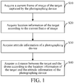
- FIG. 1 is a schematic flowchart of a method for estimating a distance to a target according to an embodiment of the present invention.
- the method for estimating a distance to a target may be applicable to a drone including a photographing device.
- the method may specifically include the following steps: Step S10: Acquire a current frame of image of the target captured by the photographing device.
- the photographing device may be a gimbal equipped on the drone and a camera mounted on the gimbal.
- the camera includes, but is not limited to, a monocular camera.
- the photographing device Before the drone starts to perform target tracking control or obstacle avoidance control, the photographing device is first used to perform real-time photographing to obtain an image sequence including the target, and send the obtained image sequence to the drone in real time.
- the image sequence includes all frames of images captured by the photographing device.
- Step S20 Acquire location information of the target according to the current frame of image.
- the location information of the target includes a height of the target and two-dimensional pixel coordinates of the target in the current frame of image.
- Step S30 Acquire attitude information of a photographing device.
- the attitude information of the photographing device includes a pitch angle of the photographing device.
- Step S40 Acquire a distance between the target and the drone according to the location information of the target and the attitude information of the photographing device.
- step S40 includes: Step S401: Acquire a smallest circumscribed rectangle of the target.
- the smallest circumscribed rectangle of the target may be a smallest circumscribed rectangular area including the target.
- the two-dimensional pixel coordinates of the target in the current frame of image are two-dimensional pixel coordinates of the smallest circumscribed rectangle in the image, and the two-dimensional pixel coordinates of the smallest circumscribed rectangle in the image include an ordinate v min of a highest point of the smallest circumscribed rectangle and an ordinate v max of a lowest point of the smallest circumscribed rectangle.
- Step S402 Acquire an angle ⁇ formed by a line connecting the highest point of the smallest circumscribed rectangle and the photographing device and a line connecting the lowest point of the smallest circumscribed rectangle and the photographing device.
- an angle ⁇ formed by the line connecting the lowest point of the smallest circumscribed rectangle and the photographing device and the optical axis of the photographing device is acquired; next, an angle ⁇ formed by the line connecting the lowest point of the smallest circumscribed rectangle and the photographing device and the optical axis of the photographing device is acquired. Then, the angle ⁇ formed by the line connecting the highest point of the smallest circumscribed rectangle and the photographing device and the line connecting the lowest point of the smallest circumscribed rectangle and the photographing device is calculated according to the obtained angle ⁇ and angle ⁇ .
- v min is the ordinate of the highest point of the smallest circumscribed rectangle
- c y is an ordinate of an optical center of the photographing device
- f y is a focal length of the photographing device in a y-axis direction.
- v max is the ordinate of the lowest point of the smallest circumscribed rectangle
- c x is an ordinate of an optical center of the photographing device
- f y is a focal length of the photographing device in the y-axis direction.
- Step S403 Acquire a distance d between the target and the drone according to the angle ⁇ and a pitch angle ⁇ of the photographing device.
- step S403 may include the following steps: Step S4031: Acquire an angle ⁇ formed by the line connecting the lowest point of the smallest circumscribed rectangle and the photographing device and a vertical direction according to the pitch angle ⁇ of the photographing device.
- Step S4032 Acquire the distance d between the target and the drone according to the angle ⁇ and the angle ⁇ .
- L 2 is a length of the line connecting the lowest point of the smallest circumscribed rectangle and the photographing device. Refer to FIG. 3 .
- the drone may be controlled to track the target according to the distance.
- autonomous obstacle avoidance control may also be performed according to the distance.
- the distance between the target and the drone in each frame is obtained by performing the above steps S10 to S40, and tracking control or obstacle avoidance control is performed according to the distance obtained for each frame, so that the drone can implement the real-time acquisition of the location of the target, tracking of the target, autonomous obstacle avoidance control, and so on.
- the present invention does not rely on the assumption that the ground is level, is not based on any other strong assumption, requires a small amount of calculation, and can estimate the three-dimensional spatial location information of the target in real time.
- the motion status of the target and the displacement status of the drone do not affect the implementation of the present invention.
- the present invention can accurately estimate the three-dimensional spatial location information of the target; when the drone has no displacement, i.e., when the drone is hovering, the present invention can accurately estimate the distance between the target and the drone, and therefore can accurately acquire the three-dimensional spatial location information of the target.
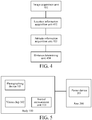
- FIG. 4 is a functional block diagram of a device for estimating a distance to a target according to an embodiment of the present invention.
- the device for estimating a distance to a target can be configured to implement the above method for estimating a distance to a target.
- the device for estimating a distance to a target according to the embodiments of the present invention may be applicable to a drone.
- the device for estimating a distance to a target may include: an image acquisition unit 401, a location information acquisition unit 402, an attitude information acquisition unit 403, and a distance determining unit 404.
- the image acquisition unit 401 is configured to acquire a current frame of image of the target.
- the location information acquisition unit 402 is configured to acquire location information of the target according to the current frame of image, where the location information includes a height of the target and two-dimensional pixel coordinates of the target in the image.
- the attitude information acquisition unit 403 is configured to acquire attitude information of a photographing device, where the attitude information includes a pitch angle of the photographing device.
- the distance determining unit 404 is configured to acquire a distance d between the target and the drone according to the location information of the target and the attitude information of the photographing device.
- the distance determining unit 404 is further configured to:
- the distance determining unit 404 is specifically configured to:
- the distance determining unit 404 may be further configured to: acquire an angle ⁇ formed by the line connecting the lowest point of the smallest circumscribed rectangle and the photographing device and the optical axis of the photographing device.
- the distance determining unit 404 may be further configured to: acquire a distance d between the target and the drone according to the angle ⁇ and a pitch angle ⁇ of the photographing device.
- the distance determining unit 404 is further configured to: acquire an angle ⁇ formed by the line connecting the lowest point of the smallest circumscribed rectangle and the photographing device and a vertical direction according to the pitch angle ⁇ of the photographing device.
- the distance determining unit 404 may be further configured to: acquire the distance d between the target and the drone according to the angle ⁇ and the angle ⁇ .
- the image acquisition unit 401 may be a photographing device equipped on a drone, where the photographing device may include a gimbal and a camera mounted on the gimbal.
- the camera includes, but is not limited to, a monocular camera.
- the location information acquisition unit 402 and the distance determining unit 404 may be a vision chip of the drone.
- the attitude information acquisition unit 403 may be an inertial measurement unit (IMU) mounted on the gimbal of the drone.
- IMU inertial measurement unit
- the present invention also provides a drone.
- the drone can be configured to implement the above method for estimating a distance to a target, can estimate the distance between the target and the drone in real time, and can also track or avoid the target according to the distance between the target and the drone that is estimated in real time.
- the drone provided in an implementation of the present invention includes a body 100, an arm 200 connected to the body 100, a power device 201 disposed on the arm 200, a photographing device 101 disposed on the body 100, a vision chip 102, and an inertial measurement unit 103 disposed on the photographing device 101.
- the vision chip 102 is electrically connected to the inertial measurement unit 103.
- the power device 201 is configured to supply power for flight of the drone.
- the power device 201 may include a motor disposed on the arm 200 and a propeller connected to the motor, and the motor is configured to drive the propeller to rotate at a high speed to provide the power required for the flight of the drone.
- the photographing device 101 is configured to acquire a current frame of image of the target.
- the photographing device 101 may be a gimbal-mounted camera equipped on the drone.
- the photographing device 101 may include a gimbal connected to the body 100 of the drone and a camera connected to the gimbal.
- the camera includes, but is not limited to, a monocular camera.
- the inertial measurement unit 103 is configured to acquire attitude information of the photographing device 101, where the attitude information includes a pitch angle of the photographing device 101.
- the inertial measurement unit 103 is disposed on the gimbal.
- the vision chip 102 is configured to perform the following actions:
- vision chip 102 may specifically be configured to perform the following actions:
- vision chip 102 may specifically be further configured to:
- vision chip 102 may specifically be further configured to:
- vision chip 102 may specifically be further configured to:
- vision chip 102 may specifically be further configured to:
- vision chip 102 may specifically be further configured to:
Landscapes
- Engineering & Computer Science (AREA)
- Remote Sensing (AREA)
- Radar, Positioning & Navigation (AREA)
- Physics & Mathematics (AREA)
- General Physics & Mathematics (AREA)
- Aviation & Aerospace Engineering (AREA)
- Automation & Control Theory (AREA)
- Multimedia (AREA)
- Signal Processing (AREA)
- Theoretical Computer Science (AREA)
- Microelectronics & Electronic Packaging (AREA)
- Mechanical Engineering (AREA)
- Computer Vision & Pattern Recognition (AREA)
- Length Measuring Devices By Optical Means (AREA)
- Image Analysis (AREA)
- Control Of Position, Course, Altitude, Or Attitude Of Moving Bodies (AREA)
Abstract
Description
- The present invention relates to the field of drones, and more specifically, to a method and device for estimating a distance to a target, and a drone.
- A drone-based intelligent following function is roughly divided into two parts, namely, target detection and following control.
- Generally, the target detection on a drone is realized by a gimbal-mounted camera equipped on the drone. For the target detection part, a target to be followed is found in an image obtained by the camera, and is marked with a rectangular frame (or other forms). The following control part is to enable the drone to follow the target while certain requirements are met (for example, the distance between the target and the drone is kept unchanged). The easiest way to implement following control is to follow the target according to the three-dimensional spatial location of the target. However, because the gimbal-mounted camera is a monocular camera, the three-dimensional spatial location of the target to be followed cannot be directly obtained from the camera.
- At present, to solve this problem, one method is to calculate the distance between the target and the drone according to a height above ground level obtained by the drone. This method relies on the accuracy of the height, but the height data is unstable, which tends to cause an increasingly larger deviation in the calculated distance. In addition, this method is based on a strong assumption that the ground is level all the time. However, in fact, there are ups and downs on the ground, which will directly void this method.
- Another method is to estimate the location of the target by triangulation. This method requires the drone to have a displacement. If the drone is hovering, the distance between the target and the drone cannot be estimated.
- A technical problem to be solved by the present invention is to overcome the defects of the prior art and provide a method and device for estimating a distance to a target, and a drone.
- A technical solution adopted in the present invention to solve the technical problem is to devise a method for estimating a distance to a target, applicable to a drone including a photographing device, the method including:
- acquiring a current frame of image of the target captured by the photographing device;
- acquiring location information of the target according to the current frame of image, where the location information includes a height of the target and two-dimensional pixel coordinates of the target in the image;
- acquiring attitude information of the photographing device, where the attitude information includes a pitch angle of the photographing device; and
- acquiring a distance between the target and the drone according to the location information of the target and the attitude information of the photographing device.
- In an embodiment, the acquiring a distance between the target and the drone according to the location information of the target and the attitude information of the photographing device includes:
- acquiring a smallest circumscribed rectangle of the target, where the two-dimensional pixel coordinates of the target in the image are two-dimensional pixel coordinates of the smallest circumscribed rectangle in the image, and the two-dimensional pixel coordinates of the smallest circumscribed rectangle in the image include an ordinate vmin of a highest point of the smallest circumscribed rectangle and an ordinate vmax of a lowest point of the smallest circumscribed rectangle;
- acquiring an angle ϕ formed by a line connecting the highest point of the smallest circumscribed rectangle and the photographing device and a line connecting the lowest point of the smallest circumscribed rectangle and the photographing device;
- acquiring a distance d between the target and the drone according to the angle ϕ and a pitch angle θ of the photographing device.
- In an embodiment, the acquiring an angle ϕ formed by a line connecting the highest point of the smallest circumscribed rectangle and the photographing device and a line connecting the lowest point of the smallest circumscribed rectangle and the photographing device includes:
- acquiring an angle α formed by the line connecting the highest point of the smallest circumscribed rectangle and the photographing device and an optical axis of the photographing device;
- acquiring an angle β formed by the line connecting the lowest point of the smallest circumscribed rectangle and the photographing device and the optical axis of the photographing device; and
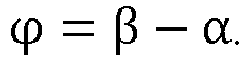
- calculating the angle ϕ using the following formula:
- In an embodiment, the acquiring an angle formed by the line connecting the highest point of the smallest circumscribed rectangle and the photographing device and an optical axis of the photographing device includes:
- calculating the angle α using the following formula:

- where vmin is the ordinate of the highest point of the smallest circumscribed rectangle, cy is an ordinate of an optical center of the photographing device, and fy is a focal length of the photographing device in a y-axis direction; and
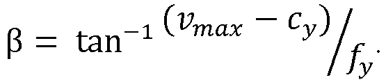
- In an embodiment, the acquiring an angle β formed by the line connecting the lowest point of the smallest circumscribed rectangle and the photographing device and an optical axis of the photographing device includes:
- calculating the angle β using the following formula:

- where vmax is the ordinate of the lowest point of the smallest circumscribed rectangle, cy is an ordinate of an optical center of the photographing device, and fy is a focal length of the photographing device in the y-axis direction; and
- In an embodiment, the acquiring a distance d between the target and the drone according to the angle ϕ and a pitch angle θ of the photographing device includes:
- acquiring an angle δ formed by the line connecting the lowest point of the smallest circumscribed rectangle and the photographing device and a vertical direction according to the pitch angle θ of the photographing device; and
- acquiring the distance d between the target and the drone according to the angle ϕ and the angle δ.
- In an embodiment, the acquiring an angle δ formed by the line connecting the lowest point of the smallest circumscribed rectangle and the photographing device and a vertical direction according to the pitch angle θ of the photographing device includes:
calculating the angle δ using the following formula:
- In an embodiment, the acquiring the distance d between the target and the drone according to the angle ϕ and the angle δ includes:
- calculating the distance d between the target and the drone using the following formula:

- where L 2 is a length of the line connecting the lowest point of the smallest circumscribed rectangle and the photographing device.
- In an embodiment, the length L 2 of the line connecting the lowest point of the smallest circumscribed rectangle and the photographing device is calculated using the following formula:


- In an embodiment, the photographing device includes a monocular camera.
- The present invention further provides a device for estimating a distance to a target, applicable to a drone, the device including:
- an image acquisition unit, configured to acquire a current frame of image of the target;
- a location information acquisition unit, configured to acquire location information of the target according to the current frame of image, where the location information includes a height of the target and two-dimensional pixel coordinates of the target in the image;
- an attitude information acquisition unit, configured to acquire attitude information of a photographing device of the drone, where the attitude information includes a pitch angle of the photographing device; and
- a distance determining unit, configured to acquire a distance d between the target and the drone according to the location information of the target and the attitude information of the photographing device.
- In an embodiment, the distance determining unit is further configured to:
- acquire a smallest circumscribed rectangle of the target, where the two-dimensional pixel coordinates of the target in the image are two-dimensional pixel coordinates of the smallest circumscribed rectangle in the image, and the two-dimensional pixel coordinates of the smallest circumscribed rectangle in the image include an ordinate vmin of a highest point of the smallest circumscribed rectangle and an ordinate vmax of a lowest point of the smallest circumscribed rectangle;
- acquire an angle ϕ formed by a line connecting the highest point of the smallest circumscribed rectangle and the photographing device and a line connecting the lowest point of the smallest circumscribed rectangle and the photographing device; and
- acquire a distance d between the target and the drone according to the angle ϕ and a pitch angle θ of the photographing device.
- In an embodiment, the distance determining unit is further configured to:
- acquire an angle α formed by the line connecting the highest point of the smallest circumscribed rectangle and the photographing device and an optical axis of the photographing device;
- acquire an angle β formed by the line connecting the lowest point of the smallest circumscribed rectangle and the photographing device and the optical axis of the photographing device; and
- calculate the angle ϕ using the following formula:

- In an embodiment, the first acquisition submodule includes: calculate the angle α using the following formula:

- In an embodiment, the distance determining unit is further configured to:
- calculate the angle β using the following formula:

- where vmax is the ordinate of the lowest point of the smallest circumscribed rectangle, cy is an ordinate of an optical center of the photographing device, and fy is a focal length of the photographing device in the y-axis direction; and
- In an embodiment, the distance determining unit is further configured to:
- acquire an angle δ formed by the line connecting the lowest point of the smallest circumscribed rectangle and the photographing device and a vertical direction according to the pitch angle θ of the photographing device; and
- acquire the distance d between the target and the drone according to the angle ϕ and the angle δ.
- In an embodiment, the distance determining unit is further configured to: calculate the angle δ using the following formula:

- In an embodiment, the distance determining unit is further configured to:
- calculate the distance d between the target and the drone using the following formula:

- where L 2 is a length of the line connecting the lowest point of the smallest circumscribed rectangle and the photographing device.
- In an embodiment, the length L 2 of the line connecting the lowest point of the smallest circumscribed rectangle and the photographing device is calculated using the following formula:


- In an embodiment, the photographing device includes a monocular camera.
- The present invention further provides a drone, including:
- a body;
- an arm, connected to the body;
- a power device, disposed on the arm and configured to supply power for flight of the drone;
- a photographing device, disposed on the body and configured to acquire a current frame of image of a target;
- an inertial measurement unit, configured to acquire attitude information of the photographing device, where the attitude information includes a pitch angle of the photographing device; and
- a vision chip, disposed on the body and electrically connected to the inertial measurement unit,
- where the vision chip is configured to:
- acquire location information of the target according to the current frame of image, where the location information includes a height of the target and two-dimensional pixel coordinates of the target in the image; and
- acquire a distance between the target and the drone according to the location information of the target and the attitude information of the photographing device.
- In an embodiment, the vision chip is further configured to:
- acquire a smallest circumscribed rectangle of the target, where the two-dimensional pixel coordinates of the target in the image are two-dimensional pixel coordinates of the smallest circumscribed rectangle in the image, and the two-dimensional pixel coordinates of the smallest circumscribed rectangle in the image include an ordinate vmin of a highest point of the smallest circumscribed rectangle and an ordinate vmax of a lowest point of the smallest circumscribed rectangle;
- acquire an angle ϕ formed by a line connecting the highest point of the smallest circumscribed rectangle and the photographing device and a line connecting the lowest point of the smallest circumscribed rectangle and the photographing device; and
- acquire a distance d between the target and the drone according to the angle ϕ and a pitch angle θ of the photographing device.
- In an embodiment, the vision chip is further configured to:
- acquire an angle α formed by the line connecting the highest point of the smallest circumscribed rectangle and the photographing device and an optical axis of the photographing device;
- acquire an angle β formed by the line connecting the lowest point of the smallest circumscribed rectangle and the photographing device and the optical axis of the photographing device; and
- calculate the angle ϕ using the following formula:

- In an embodiment, the vision chip is further configured to:
- calculate the angle α using the following formula:

- where vmin is the ordinate of the highest point of the smallest circumscribed rectangle, cy is an ordinate of an optical center of the photographing device, and fy is a focal length of the photographing device in a y-axis direction.
- In an embodiment, the vision chip is further configured to:
- calculate the angle β using the following formula:

- where vmax is the ordinate of the lowest point of the smallest circumscribed rectangle, cy is an ordinate of an optical center of the photographing device, and fy is a focal length of the photographing device in the y-axis direction; and
- In an embodiment, the vision chip is further configured to:
- acquire an angle δ formed by the line connecting the lowest point of the smallest circumscribed rectangle and the photographing device and a vertical direction according to the pitch angle θ of the photographing device; and
- acquire the distance d between the target and the drone according to the angle ϕ and the angle δ.
- In an embodiment, the vision chip is further configured to: calculate the angle δ using the following formula:

- In an embodiment, the vision chip is further configured to:
- calculate the distance d between the target and the drone using the following formula:

- where L 2 is a length of the line connecting the lowest point of the smallest circumscribed rectangle and the photographing device.
- In an embodiment, the length L 2 of the line connecting the lowest point of the smallest circumscribed rectangle and the photographing device is calculated using the following formula:


- In an embodiment, the photographing device includes a monocular camera.
- The following beneficial effects are achieved by implementing the present invention: each frame of image of the target is obtained using an image acquisition device, each frame of image is processed using a preset method to obtain motion information of the target at a moment corresponding to each frame, and computation is performed according to the motion information and equipment information of the image acquisition device at this time to finally obtain real-time spatial location information of the target in each frame, and the drone is controlled according to the real-time spatial location information of the target in each frame, to track the target. The method of the present invention can accurately calculate the spatial location information of the target, is not based on a strong assumption, requires a small amount of calculation, can estimate the spatial location information of the target in real time, and has high accuracy.
- The present invention is further described below with reference to the accompanying drawings and embodiments. In the accompanying drawings:
-
FIG. 1 is a schematic flowchart of a method for estimating a distance to a target according to an embodiment of the present invention; -
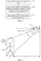
FIG. 2 is a detailed schematic flowchart of a method for estimating a distance to a target according to an embodiment of the present invention; -
FIG. 3 is a schematic diagram of a spatial location of a target according to an embodiment of the present invention; -
FIG. 4 is a functional block diagram of a device for estimating a distance to a target according to an embodiment of the present invention; and -
FIG. 5 is a schematic structural diagram of a drone according to an embodiment of the present invention. - The following clearly and completely describes the technical solutions in the embodiments of the present invention with reference to the accompanying drawings in the embodiments of the present invention. Apparently, the described embodiments are merely some rather than all of the embodiments of the present invention. All other embodiments obtained by a person of ordinary skill in the art based on the embodiments of the present invention without creative effects shall fall within the protection scope of the present invention.
- To solve the problem in the prior art that limited by conditions of a method used, three-dimensional spatial location information of the target that is estimated by a drone may become invalid or the drone cannot estimate or cannot accurately estimate the three-dimensional spatial information of the target, the embodiments of the present invention provide a method for estimating a distance to a target. This method can accurately estimate the distance between the target and the drone, does not rely on the assumption that the ground is level, is not based on a strong assumption, requires a small amount of calculation, and can estimate the three-dimensional spatial location information of the target in real time with high accuracy, thereby ensuring that the drone can achieve accurate tracking according to the estimated three-dimensional spatial location information, or ensuring that the drone can achieve autonomous obstacle avoidance control according to the estimated three-dimensional spatial location information.
- Referring to
FIG. 1 , an embodiment of the present invention provides a method for estimating a distance to a target. This method may be used by a drone to acquire a distance between the target and the drone in real time, and implement real-time tracking of the target according to the acquired distance. The target may be a moving target or a stationary target, and in the real-time tracking process, the motion status (moving or stationary) of the target does not affect the accuracy of the calculation result. In addition, obstacle avoidance may also be performed according to the acquired distance between the target and the drone. -
FIG. 1 is a schematic flowchart of a method for estimating a distance to a target according to an embodiment of the present invention. The method for estimating a distance to a target may be applicable to a drone including a photographing device. The method may specifically include the following steps:
Step S10: Acquire a current frame of image of the target captured by the photographing device. - In an embodiment of the present invention, the photographing device may be a gimbal equipped on the drone and a camera mounted on the gimbal. The camera includes, but is not limited to, a monocular camera.
- Before the drone starts to perform target tracking control or obstacle avoidance control, the photographing device is first used to perform real-time photographing to obtain an image sequence including the target, and send the obtained image sequence to the drone in real time. The image sequence includes all frames of images captured by the photographing device.
- Step S20: Acquire location information of the target according to the current frame of image.
- The location information of the target includes a height of the target and two-dimensional pixel coordinates of the target in the current frame of image.
- Step S30: Acquire attitude information of a photographing device.
- The attitude information of the photographing device includes a pitch angle of the photographing device.
- Step S40: Acquire a distance between the target and the drone according to the location information of the target and the attitude information of the photographing device.
- Specifically, as shown in
FIG. 2 , the distance d between the target and the drone may be obtained through the following steps:
In other words, in an embodiment of the present invention, step S40 includes:
Step S401: Acquire a smallest circumscribed rectangle of the target. - In an embodiment of the present invention, the smallest circumscribed rectangle of the target may be a smallest circumscribed rectangular area including the target.
- The two-dimensional pixel coordinates of the target in the current frame of image are two-dimensional pixel coordinates of the smallest circumscribed rectangle in the image, and the two-dimensional pixel coordinates of the smallest circumscribed rectangle in the image include an ordinate vmin of a highest point of the smallest circumscribed rectangle and an ordinate vmax of a lowest point of the smallest circumscribed rectangle. Specifically, as shown in
FIG. 3 :
Step S402: Acquire an angle ϕ formed by a line connecting the highest point of the smallest circumscribed rectangle and the photographing device and a line connecting the lowest point of the smallest circumscribed rectangle and the photographing device. - Specifically, in this step, first, an angle α formed by the line connecting the lowest point of the smallest circumscribed rectangle and the photographing device and the optical axis of the photographing device is acquired; next, an angle β formed by the line connecting the lowest point of the smallest circumscribed rectangle and the photographing device and the optical axis of the photographing device is acquired. Then, the angle ϕ formed by the line connecting the highest point of the smallest circumscribed rectangle and the photographing device and the line connecting the lowest point of the smallest circumscribed rectangle and the photographing device is calculated according to the obtained angle α and angle β.
- The angle ϕ may be calculated using the following formula:

- In an embodiment of the present invention, the angle α may be calculated using the following formula:

- In an embodiment of the present invention, the angle β may be calculated using the following formula:
- Step S403: Acquire a distance d between the target and the drone according to the angle ϕ and a pitch angle θ of the photographing device.
- In an embodiment of the present invention, step S403 may include the following steps:
Step S4031: Acquire an angle δ formed by the line connecting the lowest point of the smallest circumscribed rectangle and the photographing device and a vertical direction according to the pitch angle θ of the photographing device. - In an embodiment of the present invention, the angle δ may be calculated using the following formula:

- Step S4032: Acquire the distance d between the target and the drone according to the angle ϕ and the angle δ.
- In an embodiment of the present invention, the distance d between the target and the drone may be calculated using the following formula:

FIG. 3 . - Further, the length L 2 of the line connecting the lowest point of the smallest circumscribed rectangle and the photographing device is calculated using the following formula:


where L 1 is a length of the line connecting the highest point of the smallest circumscribed rectangle and the photographing device, and L is the height of the target. Refer toFIG. 3 . - Specifically, after the distance d between the target and the drone is acquired in step S40, the drone may be controlled to track the target according to the distance. Of course, it is understandable that in some other embodiments, autonomous obstacle avoidance control may also be performed according to the distance.
- It should be noted herein that in the embodiments of the present invention, for each frame of image received, the distance between the target and the drone in each frame is obtained by performing the above steps S10 to S40, and tracking control or obstacle avoidance control is performed according to the distance obtained for each frame, so that the drone can implement the real-time acquisition of the location of the target, tracking of the target, autonomous obstacle avoidance control, and so on.
- By implementing the method for estimating a distance to a target according to the present invention, the problem that it is difficult to acquire three-dimensional spatial location information of the target using a monocular camera is effectively solved. In addition, the present invention does not rely on the assumption that the ground is level, is not based on any other strong assumption, requires a small amount of calculation, and can estimate the three-dimensional spatial location information of the target in real time. Moreover, the motion status of the target and the displacement status of the drone do not affect the implementation of the present invention. In other words, regardless of whether the target is in a moving or stationary state, the present invention can accurately estimate the three-dimensional spatial location information of the target; when the drone has no displacement, i.e., when the drone is hovering, the present invention can accurately estimate the distance between the target and the drone, and therefore can accurately acquire the three-dimensional spatial location information of the target.
-
FIG. 4 is a functional block diagram of a device for estimating a distance to a target according to an embodiment of the present invention. The device for estimating a distance to a target can be configured to implement the above method for estimating a distance to a target. The device for estimating a distance to a target according to the embodiments of the present invention may be applicable to a drone. - As shown in
FIG. 4 , the device for estimating a distance to a target may include: animage acquisition unit 401, a locationinformation acquisition unit 402, an attitudeinformation acquisition unit 403, and adistance determining unit 404. - Specifically, the
image acquisition unit 401 is configured to acquire a current frame of image of the target. - The location
information acquisition unit 402 is configured to acquire location information of the target according to the current frame of image, where the location information includes a height of the target and two-dimensional pixel coordinates of the target in the image. - The attitude
information acquisition unit 403 is configured to acquire attitude information of a photographing device, where the attitude information includes a pitch angle of the photographing device. - The
distance determining unit 404 is configured to acquire a distance d between the target and the drone according to the location information of the target and the attitude information of the photographing device. - Optionally, in an embodiment of the present invention, the
distance determining unit 404 is further configured to: - acquire a smallest circumscribed rectangle of the target, where the two-dimensional pixel coordinates of the target in the image are two-dimensional pixel coordinates of the smallest circumscribed rectangle in the image, and the two-dimensional pixel coordinates of the smallest circumscribed rectangle in the image include an ordinate vmin of a highest point of the smallest circumscribed rectangle and an ordinate vmax of a lowest point of the smallest circumscribed rectangle; and
- acquire an angle ϕ formed by a line connecting the highest point of the smallest circumscribed rectangle and the photographing device and a line connecting the lowest point of the smallest circumscribed rectangle and the photographing device.
- Optionally, the
distance determining unit 404 is specifically configured to: - acquire an angle α formed by the line connecting the highest point of the smallest circumscribed rectangle and the photographing device and an optical axis of the photographing device;
- where the angle α may be calculated using the following formula:

- where vmin is the ordinate of the highest point of the smallest circumscribed rectangle, cx is an abscissa of an optical center of the photographing device, and fy is a focal length of the photographing device.
- The
distance determining unit 404 may be further configured to: acquire an angle β formed by the line connecting the lowest point of the smallest circumscribed rectangle and the photographing device and the optical axis of the photographing device.
where the angle ϕ may be calculated using the following formula:
- The angle β is calculated using the following formula:

- The
distance determining unit 404 may be further configured to: acquire a distance d between the target and the drone according to the angle ϕ and a pitch angle θ of the photographing device. - Optionally, in an embodiment of the present invention, the
distance determining unit 404 is further configured to:
acquire an angle δ formed by the line connecting the lowest point of the smallest circumscribed rectangle and the photographing device and a vertical direction according to the pitch angle θ of the photographing device. - In an embodiment of the present invention, the angle δ may be calculated using the following formula:

- The
distance determining unit 404 may be further configured to: acquire the distance d between the target and the drone according to the angle ϕ and the angle δ. - In an embodiment of the present invention, the distance d between the target and the drone is calculated using the following formula:

- Further, the length L 2 of the line connecting the lowest point of the smallest circumscribed rectangle and the photographing device is calculated using the following formula:


- In an embodiment of the present invention, the
image acquisition unit 401 may be a photographing device equipped on a drone, where the photographing device may include a gimbal and a camera mounted on the gimbal. The camera includes, but is not limited to, a monocular camera. The locationinformation acquisition unit 402 and thedistance determining unit 404 may be a vision chip of the drone. The attitudeinformation acquisition unit 403 may be an inertial measurement unit (IMU) mounted on the gimbal of the drone. - The present invention also provides a drone. The drone can be configured to implement the above method for estimating a distance to a target, can estimate the distance between the target and the drone in real time, and can also track or avoid the target according to the distance between the target and the drone that is estimated in real time.
- As shown in
FIG. 5 , the drone provided in an implementation of the present invention includes abody 100, anarm 200 connected to thebody 100, apower device 201 disposed on thearm 200, a photographingdevice 101 disposed on thebody 100, avision chip 102, and aninertial measurement unit 103 disposed on the photographingdevice 101. Thevision chip 102 is electrically connected to theinertial measurement unit 103. - In an embodiment of the present invention, the
power device 201 is configured to supply power for flight of the drone. Optionally, thepower device 201 may include a motor disposed on thearm 200 and a propeller connected to the motor, and the motor is configured to drive the propeller to rotate at a high speed to provide the power required for the flight of the drone. - In an embodiment of the present invention, the photographing
device 101 is configured to acquire a current frame of image of the target. Optionally, the photographingdevice 101 may be a gimbal-mounted camera equipped on the drone. Specifically, the photographingdevice 101 may include a gimbal connected to thebody 100 of the drone and a camera connected to the gimbal. The camera includes, but is not limited to, a monocular camera. - In an embodiment of the present invention, the
inertial measurement unit 103 is configured to acquire attitude information of the photographingdevice 101, where the attitude information includes a pitch angle of the photographingdevice 101. Specifically, theinertial measurement unit 103 is disposed on the gimbal. - In an embodiment of the present invention, the
vision chip 102 is configured to perform the following actions: - acquiring location information of the target according to the current frame of image, where the location information includes a height of the target and two-dimensional pixel coordinates of the target in the image; and
- acquiring a distance between the target and the drone according to the location information of the target and the attitude information of the photographing
device 101. - Further, the
vision chip 102 may specifically be configured to perform the following actions: - acquiring a smallest circumscribed rectangle of the target, where the two-dimensional pixel coordinates of the target in the image are two-dimensional pixel coordinates of the smallest circumscribed rectangle in the image, and the two-dimensional pixel coordinates of the smallest circumscribed rectangle in the image include an ordinate vmin of a highest point of the smallest circumscribed rectangle and an ordinate vmax of a lowest point of the smallest circumscribed rectangle; and
- acquiring an angle ϕ formed by a line connecting the highest point of the smallest circumscribed rectangle and the photographing
device 101 and a line connecting the lowest point of the smallest circumscribed rectangle and the photographingdevice 101; and - acquiring a distance d between the target and the drone according to the angle ϕ and a pitch angle θ of the photographing
device 101. - Further, the
vision chip 102 may specifically be further configured to: - acquire an angle α formed by the line connecting the highest point of the smallest circumscribed rectangle and the photographing
device 101 and an optical axis of the photographingdevice 101; and - acquire an angle β formed by the line connecting the lowest point of the smallest circumscribed rectangle and the photographing
device 101 and the optical axis of the photographingdevice 101. - The angle ϕ may be calculated using the following formula:

- Further, the
vision chip 102 may specifically be further configured to: - calculate the angle α using the following formula:

- where vmin is the ordinate of the highest point of the smallest circumscribed rectangle, cy is an ordinate of an optical center of the photographing
device 101, and fy is a focal length of the photographingdevice 101 in a y-axis direction. - Further, the
vision chip 102 may specifically be further configured to: - calculate the angle β using the following formula:

- where vmax is the ordinate of the lowest point of the smallest circumscribed rectangle, cy is an ordinate of an optical center of the photographing
device 101, and fy is a focal length of the photographingdevice 101 in a y-axis direction. - Further, the
vision chip 102 may specifically be further configured to: - acquire an angle δ formed by the line connecting the lowest point of the smallest circumscribed rectangle and the photographing
device 101 and a vertical direction according to the pitch angle θ of the photographingdevice 101; and - acquire the distance d between the target and the drone according to the angle ϕ and the angle δ.
- Further, the
vision chip 102 may specifically be further configured to:
calculate the angle δ using the following formula:
- Further, the
vision chip 102 may specifically be further configured to: - calculate the distance d between the target and the drone using the following formula:

- where L 2 is a length of the line connecting the lowest point of the smallest circumscribed rectangle and the photographing
device 101. - Further, the length L 2 of the line connecting the lowest point of the smallest circumscribed rectangle and the photographing
device 101 may be calculated using the following formula:

device 101, and L is the height of the target. - The embodiments are only for describing the technical concepts and features of the present invention, and are intended to enable a person skilled in the art to understand the present invention and to practice the same, and are not intended to limit the scope of the present invention. All equivalent changes and modifications made without departing from the scope of the claims of the present invention shall fall within the scope of the claims of the present invention.
- It is to be understood that modifications and changes can be made by those skilled in the art in accordance with the above description, which are intended to be contemplated in the protection scope of the appended claims.
Claims (30)
- A method for estimating a distance to a target, applicable to a drone comprising a photographing device, characterized by comprising:acquiring a current frame of image of the target captured by the photographing device;acquiring location information of the target according to the current frame of image, wherein the location information comprises a height of the target and two-dimensional pixel coordinates of the target in the image;acquiring attitude information of the photographing device, wherein the attitude information comprises a pitch angle of the photographing device; andacquiring a distance between the target and the drone according to the location information of the target and the attitude information of the photographing device.
- The method according to claim 1, characterized in that, the acquiring a distance between the target and the drone according to the location information of the target and the attitude information of the photographing device comprises:acquiring a smallest circumscribed rectangle of the target, where the two-dimensional pixel coordinates of the target in the image are two-dimensional pixel coordinates of the smallest circumscribed rectangle in the image, and the two-dimensional pixel coordinates of the smallest circumscribed rectangle in the image comprise an ordinate vmin of a highest point of the smallest circumscribed rectangle and an ordinate vmax of a lowest point of the smallest circumscribed rectangle;acquiring an angle ϕ formed by a line connecting the highest point of the smallest circumscribed rectangle and the photographing device and a line connecting the lowest point of the smallest circumscribed rectangle and the photographing device;acquiring a distance d between the target and the drone according to the angle ϕ and a pitch angle θ of the photographing device.
- The method according to claim 2, characterized in that, the acquiring an angle ϕ formed by a line connecting the highest point of the smallest circumscribed rectangle and the photographing device and a line connecting the lowest point of the smallest circumscribed rectangle and the photographing device comprises:acquiring an angle α formed by the line connecting the highest point of the smallest circumscribed rectangle and the photographing device and an optical axis of the photographing device;acquiring an angle β formed by the line connecting the lowest point of the smallest circumscribed rectangle and the photographing device and the optical axis of the photographing device; andcalculating the angle ϕ using the following formula:

- The method according to claim 3, wherein the acquiring an angle α formed by the line connecting the highest point of the smallest circumscribed rectangle and the photographing device and an optical axis of the photographing device comprises:calculating the angle α using the following formula:
 wherein vmin is the ordinate of the highest point of the smallest circumscribed rectangle, cy is an ordinate of an optical center of the photographing device, and fy is a focal length of the photographing device in a y-axis direction.
 - The method according to claim 3 or 4, characterized in that, the acquiring an angle β formed by the line connecting the lowest point of the smallest circumscribed rectangle and the photographing device and the optical axis of the photographing device comprises:calculating the angle β using the following formula:
 wherein vmax is the ordinate of the lowest point of the smallest circumscribed rectangle, cy is an ordinate of an optical center of the photographing device, and fy is a focal length of the photographing device in the y-axis direction.
 - The method according to any of claims 3-5, characterized in that, the acquiring a distance d between the target and the drone according to the angle ϕ and a pitch angle θ of the photographing device comprises:acquiring an angle δ formed by the line connecting the lowest point of the smallest circumscribed rectangle and the photographing device and a vertical direction according to the pitch angle θ of the photographing device; andacquiring the distance d between the target and the drone according to the angle ϕ and the angle δ.
- The method according to claim 6, characterized in that, the acquiring an angle δ formed by the line connecting the lowest point of the smallest circumscribed rectangle and the photographing device and a vertical direction according to the pitch angle θ of the photographing device comprises:
calculating the angle δ using the following formula:
- The method according to claim 6 or 7, wherein the acquiring the distance d between the target and the drone according to the angle ϕ and the angle δ comprises:calculating the distance d between the target and the drone using the following formula:
 wherein L 2 is a length of the line connecting the lowest point of the smallest circumscribed rectangle and the photographing device.
 - The method according to claim 8, wherein the length L 2 of the line connecting the lowest point of the smallest circumscribed rectangle and the photographing device is calculated using the following formula:


- The method according to any of claims 1-9, wherein the photographing device comprises a monocular camera.
- A device for estimating a distance to a target, applicable to a drone, characterized by comprising:an image acquisition unit, configured to acquire a current frame of image of the target;a location information acquisition unit, configured to acquire location information of the target according to the current frame of image, wherein the location information comprises a height of the target and two-dimensional pixel coordinates of the target in the image;an attitude information acquisition unit, configured to acquire attitude information of a photographing device of the drone, wherein the attitude information comprises a pitch angle of the photographing device; anda distance determining unit, configured to acquire a distance between the target and the drone according to the location information of the target and the attitude information of the photographing device.
- The device for estimating a distance to a target according to claim 11, characterized in that, the distance determining unit is further configured to:acquire a smallest circumscribed rectangle of the target, where the two-dimensional pixel coordinates of the target in the image are two-dimensional pixel coordinates of the smallest circumscribed rectangle in the image, and the two-dimensional pixel coordinates of the smallest circumscribed rectangle in the image comprise an ordinate vmin of a highest point of the smallest circumscribed rectangle and an ordinate vmax of a lowest point of the smallest circumscribed rectangle;acquire an angle ϕ formed by a line connecting the highest point of the smallest circumscribed rectangle and the photographing device and a line connecting the lowest point of the smallest circumscribed rectangle and the photographing device; andacquire a distance d between the target and the drone according to the angle ϕ and a pitch angle θ of the photographing device.
- The device for estimating a distance to a target according to claim 12, characterized in that, the distance determining unit is further configured to:acquire an angle α formed by the line connecting the highest point of the smallest circumscribed rectangle and the photographing device and an optical axis of the photographing device;acquire an angle β formed by the line connecting the lowest point of the smallest circumscribed rectangle and the photographing device and the optical axis of the photographing device; andcalculate the angle ϕ using the following formula:

- The device for estimating a distance to a target according to claim 13, characterized in that, the distance determining unit is further configured to:calculate the angle α using the following formula:
 wherein vmin is the ordinate of the highest point of the smallest circumscribed rectangle, cy is an ordinate of an optical center of the photographing device, and fy is a focal length of the photographing device in a y-axis direction.
 - The device for estimating a distance to a target according to claim 13 or 14, characterized in that, the distance determining unit is further configured to:calculate the angle β using the following formula:
 wherein vmax is the ordinate of the lowest point of the smallest circumscribed rectangle, cy is an ordinate of an optical center of the photographing device, and fy is a focal length of the photographing device in the y-axis direction.
 - The device for estimating a distance to a target according to any of claims 13-15, characterized in that, the distance determining unit is further configured to:acquire an angle δ formed by the line connecting the lowest point of the smallest circumscribed rectangle and the photographing device and a vertical direction according to the pitch angle θ of the photographing device; andacquire the distance d between the target and the drone according to the angle ϕ and the angle δ.
- The device for estimating a distance to a target according to claim 16, characterized in that, the distance determining unit is further configured to:
calculate the angle δ using the following formula:
- The device for estimating a distance to a target according to claim 16 or 17, characterized in that, the distance determining unit is further configured to:calculate the distance d between the target and the drone using the following formula:
 wherein L 2 is a length of the line connecting the lowest point of the smallest circumscribed rectangle and the photographing device.
 - The device for estimating a distance to a target according to claim 18, characterized in that, the length L 2 of the line connecting the lowest point of the smallest circumscribed rectangle and the photographing device is calculated using the following formula:


- The device for estimating a distance to a target according to any of claims 11-19, characterized in that, the photographing device comprises a monocular camera.
- A drone, characterized by comprising:a body;an arm, connected to the body;a power device, disposed on the arm and configured to supply power for flight of the drone;a photographing device, disposed on the body and configured to acquire a current frame of image of a target;an inertial measurement unit, configured to acquire attitude information of the photographing device, wherein the attitude information comprises a pitch angle of the photographing device; anda vision chip, disposed on the body and electrically connected to the inertial measurement unit,wherein the vision chip is configured to:acquire location information of the target according to the current frame of image, wherein the location information comprises a height of the target and two-dimensional pixel coordinates of the target in the image; andacquire a distance between the target and the drone according to the location information of the target and the attitude information of the photographing device.
- The drone according to claim 21, characterized in that, the vision chip is further configured to:acquire a smallest circumscribed rectangle of the target, where the two-dimensional pixel coordinates of the target in the image are two-dimensional pixel coordinates of the smallest circumscribed rectangle in the image, and the two-dimensional pixel coordinates of the smallest circumscribed rectangle in the image comprise an ordinate vmin of a highest point of the smallest circumscribed rectangle and an ordinate vmax of a lowest point of the smallest circumscribed rectangle;acquire an angle ϕ formed by a line connecting the highest point of the smallest circumscribed rectangle and the photographing device and a line connecting the lowest point of the smallest circumscribed rectangle and the photographing device; andacquire a distance d between the target and the drone according to the angle ϕ and a pitch angle θ of the photographing device.
- The drone according to claim 22, characterized in that, the vision chip is further configured to:acquire an angle α formed by the line connecting the highest point of the smallest circumscribed rectangle and the photographing device and an optical axis of the photographing device;acquire an angle β formed by the line connecting the lowest point of the smallest circumscribed rectangle and the photographing device and the optical axis of the photographing device; andcalculate the angle ϕ using the following formula:

- The drone according to claim 23, wherein the vision chip is further configured to:calculate the angle α using the following formula:
 wherein vmin is the ordinate of the highest point of the smallest circumscribed rectangle, cy is an ordinate of an optical center of the photographing device, and fy is a focal length of the photographing device in a y-axis direction.
 - The drone according to claim 23 or 24, characterized in that, the vision chip is further configured to:calculate the angle β using the following formula:
 wherein vmax is the ordinate of the lowest point of the smallest circumscribed rectangle, cy is an ordinate of an optical center of the photographing device, and fy is a focal length of the photographing device in the y-axis direction.
 - The drone according to any of claims 23-25, characterized in that, the vision chip is further configured to:acquire an angle δ formed by the line connecting the lowest point of the smallest circumscribed rectangle and the photographing device and a vertical direction according to the pitch angle θ of the photographing device; andacquire the distance d between the target and the drone according to the angle ϕ and the angle δ.
- The drone according to claim 26, characterized in that, the vision chip is further configured to:
calculate the angle δ using the following formula:
- The drone according to claim 26 or 27, characterized in that, the vision chip is further configured to:calculate the distance d between the target and the drone using the following formula:
 wherein L 2 is a length of the line connecting the lowest point of the smallest circumscribed rectangle and the photographing device.
 - The drone according to claim 28, characterized in that, the length L 2 of the line connecting the lowest point of the smallest circumscribed rectangle and the photographing device is calculated using the following formula:


- The drone according to any of claims 21-29, characterized in that, the photographing device comprises a monocular camera.
Applications Claiming Priority (2)
| Application Number | Priority Date | Filing Date | Title |
|---|---|---|---|
| CN201811580979.9A CN109754420B (en) | 2018-12-24 | 2018-12-24 | Target distance estimation method and device and unmanned aerial vehicle |
| PCT/CN2019/128058 WO2020135447A1 (en) | 2018-12-24 | 2019-12-24 | Target distance estimation method and device, and unmanned aerial vehicle |
Publications (3)
| Publication Number | Publication Date |
|---|---|
| EP3905197A1 true EP3905197A1 (en) | 2021-11-03 |
| EP3905197A4 EP3905197A4 (en) | 2022-02-23 |
| EP3905197B1 EP3905197B1 (en) | 2025-07-23 |
Family
ID=66402910
Family Applications (1)
| Application Number | Title | Priority Date | Filing Date |
|---|---|---|---|
| EP19905518.7A Active EP3905197B1 (en) | 2018-12-24 | 2019-12-24 | Target distance estimation method and device, and unmanned aerial vehicle |
Country Status (4)
| Country | Link |
|---|---|
| US (1) | US11747833B2 (en) |
| EP (1) | EP3905197B1 (en) |
| CN (1) | CN109754420B (en) |
| WO (1) | WO2020135447A1 (en) |
Families Citing this family (9)
| Publication number | Priority date | Publication date | Assignee | Title |
|---|---|---|---|---|
| CN109754420B (en) * | 2018-12-24 | 2021-11-12 | 深圳市道通智能航空技术股份有限公司 | Target distance estimation method and device and unmanned aerial vehicle |
| CN110570463B (en) | 2019-09-11 | 2023-04-07 | 深圳市道通智能航空技术股份有限公司 | Target state estimation method and device and unmanned aerial vehicle |
| JP7394240B2 (en) * | 2020-06-03 | 2023-12-07 | グーグル エルエルシー | Depth estimation based on the bottom edge position of the subject |
| CN113167577A (en) * | 2020-06-22 | 2021-07-23 | 深圳市大疆创新科技有限公司 | Surveying method for a movable platform, movable platform and storage medium |
| KR20230020853A (en) * | 2021-08-04 | 2023-02-13 | 주식회사 넥스트칩 | Object detection method and electronic device performing the method |
| US12014508B2 (en) | 2021-10-18 | 2024-06-18 | Ford Global Technologies, Llc | Distance determination from image data |
| US12423953B2 (en) | 2022-06-30 | 2025-09-23 | Ford Global Technologies, Llc | Distance determination from image data |
| CN119126843B (en) * | 2024-08-05 | 2025-09-30 | 浙江大学 | A vision-based UAV synchronous positioning, tracking and control system |
| CN119826870B (en) * | 2025-03-18 | 2025-05-23 | 中国人民解放军海军工程大学 | A method and system for measuring the positioning accuracy of a drone on a water surface target |
Family Cites Families (19)
| Publication number | Priority date | Publication date | Assignee | Title |
|---|---|---|---|---|
| US9342746B1 (en) * | 2011-03-17 | 2016-05-17 | UtopiaCompression Corporation | Maneuverless passive range estimation using monocular image sequences |
| CN103075998B (en) * | 2012-12-31 | 2015-08-26 | 华中科技大学 | A kind of monocular extraterrestrial target range finding angle-measuring method |
| CN103604427B (en) * | 2013-12-10 | 2016-10-12 | 中国航天空气动力技术研究院 | UAS and method to ground moving target dynamic location |
| CN103822615B (en) * | 2014-02-25 | 2016-01-20 | 北京航空航天大学 | A kind of multi-control point extracts and the unmanned aerial vehicle target real-time location method be polymerized automatically |
| KR101614654B1 (en) * | 2015-06-02 | 2016-04-21 | 동의대학교 산학협력단 | Distance measurement of objects from droned with a monocular camera and GPS location data |
| CN107209854A (en) * | 2015-09-15 | 2017-09-26 | 深圳市大疆创新科技有限公司 | Systems and methods for supporting smooth object following |
| CN105698762B (en) * | 2016-01-15 | 2018-02-23 | 中国人民解放军国防科学技术大学 | Target method for rapidly positioning based on observation station at different moments on a kind of unit flight path |
| CN106054929B (en) * | 2016-06-27 | 2018-10-16 | 西北工业大学 | A kind of unmanned plane based on light stream lands bootstrap technique automatically |
| CN106326892B (en) * | 2016-08-01 | 2020-06-09 | 西南科技大学 | A visual landing pose estimation method for rotary-wing UAV |
| US10033980B2 (en) * | 2016-08-22 | 2018-07-24 | Amazon Technologies, Inc. | Determining stereo distance information using imaging devices integrated into propeller blades |
| CN106373159A (en) * | 2016-08-30 | 2017-02-01 | 中国科学院长春光学精密机械与物理研究所 | Simplified unmanned aerial vehicle multi-target location method |
| CN106570820B (en) * | 2016-10-18 | 2019-12-03 | 浙江工业大学 | A monocular vision 3D feature extraction method based on quadrotor UAV |
| CN107247458A (en) * | 2017-05-24 | 2017-10-13 | 中国电子科技集团公司第二十八研究所 | UAV Video image object alignment system, localization method and cloud platform control method |
| CN108476288B (en) * | 2017-05-24 | 2021-05-07 | 深圳市大疆创新科技有限公司 | Shooting control method and device |
| CN107452037B (en) * | 2017-08-02 | 2021-05-14 | 北京航空航天大学青岛研究院 | GPS auxiliary information acceleration-based structure recovery method from movement |
| CN107729808B (en) * | 2017-09-08 | 2020-05-01 | 国网山东省电力公司电力科学研究院 | An image intelligent acquisition system and method for unmanned aerial vehicle inspection of transmission lines |
| CN107798685B (en) * | 2017-11-03 | 2019-12-03 | 北京旷视科技有限公司 | Pedestrian's height determines method, apparatus and system |
| CN108107920A (en) * | 2017-12-19 | 2018-06-01 | 天津工业大学 | A kind of microminiature twin shaft vision stablizes holder target detection tracing system |
| CN109754420B (en) * | 2018-12-24 | 2021-11-12 | 深圳市道通智能航空技术股份有限公司 | Target distance estimation method and device and unmanned aerial vehicle |
-
2018
- 2018-12-24 CN CN201811580979.9A patent/CN109754420B/en active Active
-
2019
- 2019-12-24 WO PCT/CN2019/128058 patent/WO2020135447A1/en not_active Ceased
- 2019-12-24 EP EP19905518.7A patent/EP3905197B1/en active Active
-
2021
- 2021-06-24 US US17/356,656 patent/US11747833B2/en active Active
Also Published As
| Publication number | Publication date |
|---|---|
| US11747833B2 (en) | 2023-09-05 |
| CN109754420B (en) | 2021-11-12 |
| CN109754420A (en) | 2019-05-14 |
| WO2020135447A1 (en) | 2020-07-02 |
| EP3905197B1 (en) | 2025-07-23 |
| EP3905197A4 (en) | 2022-02-23 |
| US20210325912A1 (en) | 2021-10-21 |
Similar Documents
| Publication | Publication Date | Title |
|---|---|---|
| US11747833B2 (en) | Method and device for estimating distance to target, and unmanned aerial vehicle | |
| US20200221062A1 (en) | Image processing method and device | |
| US20210319575A1 (en) | Target positioning method and device, and unmanned aerial vehicle | |
| CN106681353B (en) | Obstacle avoidance method and system for UAV based on binocular vision and optical flow fusion | |
| CN111448476B (en) | Technology to share mapping data between unmanned aerial vehicles and ground vehicles | |
| CN108323190B (en) | Obstacle avoidance method and device and unmanned aerial vehicle | |
| US20200191556A1 (en) | Distance mesurement method by an unmanned aerial vehicle (uav) and uav | |
| EP3531375B1 (en) | Method and apparatus for measuring distance, and unmanned aerial vehicle | |
| US20250146847A1 (en) | Control method and device, aerial vehicle, movable platform, and storage medium | |
| EP3972235A1 (en) | Focusing method and apparatus, aerial photography camera, and unmanned aerial vehicle | |
| CN110427042A (en) | Unmanned plane low latitude barrier-avoiding method based on ultrasonic wave and binocular vision | |
| WO2018120040A1 (en) | Obstacle detection method and device | |
| CN112215214A (en) | Method and system for adjusting camera offset of intelligent vehicle-mounted terminal | |
| CN110427049A (en) | Multi-rotor unmanned aerial vehicle selectivity barrier-avoiding method based on binocular vision and ultrasonic wave | |
| US20210256732A1 (en) | Image processing method and unmanned aerial vehicle | |
| WO2022193081A1 (en) | Method and apparatus for controlling unmanned aerial vehicle, and unmanned aerial vehicle | |
| CN110456793B (en) | Unmanned ship autonomous mooring method and device and unmanned ship | |
| US12475599B2 (en) | Method and apparatus for calibrating extrinsic parameters of surround-view cameras on a vehicle, vehicle and storage media | |
| WO2021238743A1 (en) | Flight control method and apparatus for unmanned aerial vehicle, and unmanned aerial vehicle | |
| JP2020064029A (en) | Mobile control device | |
| WO2021056144A1 (en) | Method and apparatus for controlling return of movable platform, and movable platform | |
| CN111260538A (en) | Positioning and vehicle-mounted terminal based on long-baseline binocular fisheye camera | |
| CN115202395A (en) | A UAV landing control method, control device and storage medium | |
| CN116934849A (en) | Pose determination method, pose determination device, electronic equipment and readable storage medium | |
| WO2022188174A1 (en) | Movable platform, control method of movable platform, and storage medium |
Legal Events
| Date | Code | Title | Description |
|---|---|---|---|
| STAA | Information on the status of an ep patent application or granted ep patent |
Free format text: STATUS: THE INTERNATIONAL PUBLICATION HAS BEEN MADE |
|
| PUAI | Public reference made under article 153(3) epc to a published international application that has entered the european phase |
Free format text: ORIGINAL CODE: 0009012 |
|
| STAA | Information on the status of an ep patent application or granted ep patent |
Free format text: STATUS: REQUEST FOR EXAMINATION WAS MADE |
|
| 17P | Request for examination filed |
Effective date: 20210712 |
|
| AK | Designated contracting states |
Kind code of ref document: A1 Designated state(s): AL AT BE BG CH CY CZ DE DK EE ES FI FR GB GR HR HU IE IS IT LI LT LU LV MC MK MT NL NO PL PT RO RS SE SI SK SM TR |
|
| A4 | Supplementary search report drawn up and despatched |
Effective date: 20220125 |
|
| RIC1 | Information provided on ipc code assigned before grant |
Ipc: G05D 1/00 20060101ALI20220119BHEP Ipc: G06T 7/70 20170101AFI20220119BHEP |
|
| DAV | Request for validation of the european patent (deleted) | ||
| DAX | Request for extension of the european patent (deleted) | ||
| REG | Reference to a national code |
Ref country code: DE Ref legal event code: R079 Free format text: PREVIOUS MAIN CLASS: G06T0007700000 Ipc: B64U0020870000 Ref country code: DE Ref legal event code: R079 Ref document number: 602019073080 Country of ref document: DE Free format text: PREVIOUS MAIN CLASS: G06T0007700000 Ipc: B64U0020870000 |
|
| GRAP | Despatch of communication of intention to grant a patent |
Free format text: ORIGINAL CODE: EPIDOSNIGR1 |
|
| STAA | Information on the status of an ep patent application or granted ep patent |
Free format text: STATUS: GRANT OF PATENT IS INTENDED |
|
| RIC1 | Information provided on ipc code assigned before grant |
Ipc: G01C 21/16 20060101ALI20250213BHEP Ipc: H04N 23/61 20230101ALI20250213BHEP Ipc: G05D 1/00 20060101ALI20250213BHEP Ipc: H04N 23/695 20230101ALI20250213BHEP Ipc: G06V 20/17 20220101ALI20250213BHEP Ipc: G06T 7/50 20170101ALI20250213BHEP Ipc: B64U 101/30 20230101ALI20250213BHEP Ipc: B64U 20/87 20230101AFI20250213BHEP |
|
| INTG | Intention to grant announced |
Effective date: 20250228 |
|
| GRAS | Grant fee paid |
Free format text: ORIGINAL CODE: EPIDOSNIGR3 |
|
| GRAA | (expected) grant |
Free format text: ORIGINAL CODE: 0009210 |
|
| STAA | Information on the status of an ep patent application or granted ep patent |
Free format text: STATUS: THE PATENT HAS BEEN GRANTED |
|
| AK | Designated contracting states |
Kind code of ref document: B1 Designated state(s): AL AT BE BG CH CY CZ DE DK EE ES FI FR GB GR HR HU IE IS IT LI LT LU LV MC MK MT NL NO PL PT RO RS SE SI SK SM TR |
|
| REG | Reference to a national code |
Ref country code: GB Ref legal event code: FG4D |
|
| REG | Reference to a national code |
Ref country code: CH Ref legal event code: EP |
|
| REG | Reference to a national code |
Ref country code: DE Ref legal event code: R096 Ref document number: 602019073080 Country of ref document: DE |
|
| REG | Reference to a national code |
Ref country code: IE Ref legal event code: FG4D |
|
| REG | Reference to a national code |
Ref country code: NL Ref legal event code: MP Effective date: 20250723 |
|
| PG25 | Lapsed in a contracting state [announced via postgrant information from national office to epo] |
Ref country code: PT Free format text: LAPSE BECAUSE OF FAILURE TO SUBMIT A TRANSLATION OF THE DESCRIPTION OR TO PAY THE FEE WITHIN THE PRESCRIBED TIME-LIMIT Effective date: 20251124 |
|
| PG25 | Lapsed in a contracting state [announced via postgrant information from national office to epo] |
Ref country code: NL Free format text: LAPSE BECAUSE OF FAILURE TO SUBMIT A TRANSLATION OF THE DESCRIPTION OR TO PAY THE FEE WITHIN THE PRESCRIBED TIME-LIMIT Effective date: 20250723 |
|
| REG | Reference to a national code |
Ref country code: AT Ref legal event code: MK05 Ref document number: 1816220 Country of ref document: AT Kind code of ref document: T Effective date: 20250723 |
|
| PG25 | Lapsed in a contracting state [announced via postgrant information from national office to epo] |
Ref country code: IS Free format text: LAPSE BECAUSE OF FAILURE TO SUBMIT A TRANSLATION OF THE DESCRIPTION OR TO PAY THE FEE WITHIN THE PRESCRIBED TIME-LIMIT Effective date: 20251123 |
|
| PGFP | Annual fee paid to national office [announced via postgrant information from national office to epo] |
Ref country code: DE Payment date: 20251211 Year of fee payment: 7 |
|
| PG25 | Lapsed in a contracting state [announced via postgrant information from national office to epo] |
Ref country code: NO Free format text: LAPSE BECAUSE OF FAILURE TO SUBMIT A TRANSLATION OF THE DESCRIPTION OR TO PAY THE FEE WITHIN THE PRESCRIBED TIME-LIMIT Effective date: 20251023 |
|
| REG | Reference to a national code |
Ref country code: LT Ref legal event code: MG9D |
|
| PG25 | Lapsed in a contracting state [announced via postgrant information from national office to epo] |
Ref country code: AT Free format text: LAPSE BECAUSE OF FAILURE TO SUBMIT A TRANSLATION OF THE DESCRIPTION OR TO PAY THE FEE WITHIN THE PRESCRIBED TIME-LIMIT Effective date: 20250723 |
|
| PG25 | Lapsed in a contracting state [announced via postgrant information from national office to epo] |
Ref country code: FI Free format text: LAPSE BECAUSE OF FAILURE TO SUBMIT A TRANSLATION OF THE DESCRIPTION OR TO PAY THE FEE WITHIN THE PRESCRIBED TIME-LIMIT Effective date: 20250723 |
|
| PG25 | Lapsed in a contracting state [announced via postgrant information from national office to epo] |
Ref country code: HR Free format text: LAPSE BECAUSE OF FAILURE TO SUBMIT A TRANSLATION OF THE DESCRIPTION OR TO PAY THE FEE WITHIN THE PRESCRIBED TIME-LIMIT Effective date: 20250723 |
|
| PGFP | Annual fee paid to national office [announced via postgrant information from national office to epo] |
Ref country code: FR Payment date: 20251229 Year of fee payment: 7 |
|
| PG25 | Lapsed in a contracting state [announced via postgrant information from national office to epo] |
Ref country code: GR Free format text: LAPSE BECAUSE OF FAILURE TO SUBMIT A TRANSLATION OF THE DESCRIPTION OR TO PAY THE FEE WITHIN THE PRESCRIBED TIME-LIMIT Effective date: 20251024 |
|
| PG25 | Lapsed in a contracting state [announced via postgrant information from national office to epo] |
Ref country code: SE Free format text: LAPSE BECAUSE OF FAILURE TO SUBMIT A TRANSLATION OF THE DESCRIPTION OR TO PAY THE FEE WITHIN THE PRESCRIBED TIME-LIMIT Effective date: 20250723 |
|
| PG25 | Lapsed in a contracting state [announced via postgrant information from national office to epo] |
Ref country code: LV Free format text: LAPSE BECAUSE OF FAILURE TO SUBMIT A TRANSLATION OF THE DESCRIPTION OR TO PAY THE FEE WITHIN THE PRESCRIBED TIME-LIMIT Effective date: 20250723 |
|
| PG25 | Lapsed in a contracting state [announced via postgrant information from national office to epo] |
Ref country code: PL Free format text: LAPSE BECAUSE OF FAILURE TO SUBMIT A TRANSLATION OF THE DESCRIPTION OR TO PAY THE FEE WITHIN THE PRESCRIBED TIME-LIMIT Effective date: 20250723 Ref country code: BG Free format text: LAPSE BECAUSE OF FAILURE TO SUBMIT A TRANSLATION OF THE DESCRIPTION OR TO PAY THE FEE WITHIN THE PRESCRIBED TIME-LIMIT Effective date: 20250723 |
|
| PG25 | Lapsed in a contracting state [announced via postgrant information from national office to epo] |
Ref country code: RS Free format text: LAPSE BECAUSE OF FAILURE TO SUBMIT A TRANSLATION OF THE DESCRIPTION OR TO PAY THE FEE WITHIN THE PRESCRIBED TIME-LIMIT Effective date: 20251023 |
|
| PG25 | Lapsed in a contracting state [announced via postgrant information from national office to epo] |
Ref country code: ES Free format text: LAPSE BECAUSE OF FAILURE TO SUBMIT A TRANSLATION OF THE DESCRIPTION OR TO PAY THE FEE WITHIN THE PRESCRIBED TIME-LIMIT Effective date: 20250723 |
|
| PG25 | Lapsed in a contracting state [announced via postgrant information from national office to epo] |
Ref country code: RO Free format text: LAPSE BECAUSE OF FAILURE TO SUBMIT A TRANSLATION OF THE DESCRIPTION OR TO PAY THE FEE WITHIN THE PRESCRIBED TIME-LIMIT Effective date: 20250723 |
|
| PG25 | Lapsed in a contracting state [announced via postgrant information from national office to epo] |
Ref country code: SM Free format text: LAPSE BECAUSE OF FAILURE TO SUBMIT A TRANSLATION OF THE DESCRIPTION OR TO PAY THE FEE WITHIN THE PRESCRIBED TIME-LIMIT Effective date: 20250723 |
|
| PG25 | Lapsed in a contracting state [announced via postgrant information from national office to epo] |
Ref country code: DK Free format text: LAPSE BECAUSE OF FAILURE TO SUBMIT A TRANSLATION OF THE DESCRIPTION OR TO PAY THE FEE WITHIN THE PRESCRIBED TIME-LIMIT Effective date: 20250723 |
|
| PG25 | Lapsed in a contracting state [announced via postgrant information from national office to epo] |
Ref country code: IT Free format text: LAPSE BECAUSE OF FAILURE TO SUBMIT A TRANSLATION OF THE DESCRIPTION OR TO PAY THE FEE WITHIN THE PRESCRIBED TIME-LIMIT Effective date: 20250723 |
|
| PG25 | Lapsed in a contracting state [announced via postgrant information from national office to epo] |
Ref country code: CZ Free format text: LAPSE BECAUSE OF FAILURE TO SUBMIT A TRANSLATION OF THE DESCRIPTION OR TO PAY THE FEE WITHIN THE PRESCRIBED TIME-LIMIT Effective date: 20250723 |
|
| PG25 | Lapsed in a contracting state [announced via postgrant information from national office to epo] |
Ref country code: SK Free format text: LAPSE BECAUSE OF FAILURE TO SUBMIT A TRANSLATION OF THE DESCRIPTION OR TO PAY THE FEE WITHIN THE PRESCRIBED TIME-LIMIT Effective date: 20250723 Ref country code: EE Free format text: LAPSE BECAUSE OF FAILURE TO SUBMIT A TRANSLATION OF THE DESCRIPTION OR TO PAY THE FEE WITHIN THE PRESCRIBED TIME-LIMIT Effective date: 20250723 |