EP3904922A1 - Optical lens and method for manufacturing same - Google Patents
Optical lens and method for manufacturing same Download PDFInfo
- Publication number
- EP3904922A1 EP3904922A1 EP19903119.6A EP19903119A EP3904922A1 EP 3904922 A1 EP3904922 A1 EP 3904922A1 EP 19903119 A EP19903119 A EP 19903119A EP 3904922 A1 EP3904922 A1 EP 3904922A1
- Authority
- EP
- European Patent Office
- Prior art keywords
- group
- lens
- formula
- optical lens
- edge part
- Prior art date
- Legal status (The legal status is an assumption and is not a legal conclusion. Google has not performed a legal analysis and makes no representation as to the accuracy of the status listed.)
- Pending
Links
- CDNOQFGMIYTUEJ-UHFFFAOYSA-N CCCC(C)c(ccc(C1(c(cccc2)c2-c2c1cccc2)c1ccc(CCCOC)c(-c2ccccc2)c1)c1)c1-c1ccccc1 Chemical compound CCCC(C)c(ccc(C1(c(cccc2)c2-c2c1cccc2)c1ccc(CCCOC)c(-c2ccccc2)c1)c1)c1-c1ccccc1 CDNOQFGMIYTUEJ-UHFFFAOYSA-N 0.000 description 1
Images


Classifications
-
- G—PHYSICS
- G02—OPTICS
- G02B—OPTICAL ELEMENTS, SYSTEMS OR APPARATUS
- G02B1/00—Optical elements characterised by the material of which they are made; Optical coatings for optical elements
- G02B1/04—Optical elements characterised by the material of which they are made; Optical coatings for optical elements made of organic materials, e.g. plastics
- G02B1/041—Lenses
-
- B—PERFORMING OPERATIONS; TRANSPORTING
- B29—WORKING OF PLASTICS; WORKING OF SUBSTANCES IN A PLASTIC STATE IN GENERAL
- B29C—SHAPING OR JOINING OF PLASTICS; SHAPING OF MATERIAL IN A PLASTIC STATE, NOT OTHERWISE PROVIDED FOR; AFTER-TREATMENT OF THE SHAPED PRODUCTS, e.g. REPAIRING
- B29C31/00—Handling, e.g. feeding of the material to be shaped, storage of plastics material before moulding; Automation, i.e. automated handling lines in plastics processing plants, e.g. using manipulators or robots
- B29C31/008—Handling preformed parts, e.g. inserts
-
- B—PERFORMING OPERATIONS; TRANSPORTING
- B29—WORKING OF PLASTICS; WORKING OF SUBSTANCES IN A PLASTIC STATE IN GENERAL
- B29D—PRODUCING PARTICULAR ARTICLES FROM PLASTICS OR FROM SUBSTANCES IN A PLASTIC STATE
- B29D11/00—Producing optical elements, e.g. lenses or prisms
- B29D11/00009—Production of simple or compound lenses
-
- C—CHEMISTRY; METALLURGY
- C08—ORGANIC MACROMOLECULAR COMPOUNDS; THEIR PREPARATION OR CHEMICAL WORKING-UP; COMPOSITIONS BASED THEREON
- C08G—MACROMOLECULAR COMPOUNDS OBTAINED OTHERWISE THAN BY REACTIONS ONLY INVOLVING UNSATURATED CARBON-TO-CARBON BONDS
- C08G64/00—Macromolecular compounds obtained by reactions forming a carbonic ester link in the main chain of the macromolecule
- C08G64/20—General preparatory processes
- C08G64/30—General preparatory processes using carbonates
- C08G64/305—General preparatory processes using carbonates and alcohols
-
- C—CHEMISTRY; METALLURGY
- C08—ORGANIC MACROMOLECULAR COMPOUNDS; THEIR PREPARATION OR CHEMICAL WORKING-UP; COMPOSITIONS BASED THEREON
- C08G—MACROMOLECULAR COMPOUNDS OBTAINED OTHERWISE THAN BY REACTIONS ONLY INVOLVING UNSATURATED CARBON-TO-CARBON BONDS
- C08G65/00—Macromolecular compounds obtained by reactions forming an ether link in the main chain of the macromolecule
- C08G65/34—Macromolecular compounds obtained by reactions forming an ether link in the main chain of the macromolecule from hydroxy compounds or their metallic derivatives
-
- C—CHEMISTRY; METALLURGY
- C08—ORGANIC MACROMOLECULAR COMPOUNDS; THEIR PREPARATION OR CHEMICAL WORKING-UP; COMPOSITIONS BASED THEREON
- C08K—Use of inorganic or non-macromolecular organic substances as compounding ingredients
- C08K3/00—Use of inorganic substances as compounding ingredients
- C08K3/01—Use of inorganic substances as compounding ingredients characterized by their specific function
- C08K3/013—Fillers, pigments or reinforcing additives
-
- C—CHEMISTRY; METALLURGY
- C08—ORGANIC MACROMOLECULAR COMPOUNDS; THEIR PREPARATION OR CHEMICAL WORKING-UP; COMPOSITIONS BASED THEREON
- C08L—COMPOSITIONS OF MACROMOLECULAR COMPOUNDS
- C08L25/00—Compositions of, homopolymers or copolymers of compounds having one or more unsaturated aliphatic radicals, each having only one carbon-to-carbon double bond, and at least one being terminated by an aromatic carbocyclic ring; Compositions of derivatives of such polymers
- C08L25/02—Homopolymers or copolymers of hydrocarbons
-
- C—CHEMISTRY; METALLURGY
- C08—ORGANIC MACROMOLECULAR COMPOUNDS; THEIR PREPARATION OR CHEMICAL WORKING-UP; COMPOSITIONS BASED THEREON
- C08L—COMPOSITIONS OF MACROMOLECULAR COMPOUNDS
- C08L65/00—Compositions of macromolecular compounds obtained by reactions forming a carbon-to-carbon link in the main chain; Compositions of derivatives of such polymers
-
- G—PHYSICS
- G02—OPTICS
- G02B—OPTICAL ELEMENTS, SYSTEMS OR APPARATUS
- G02B3/00—Simple or compound lenses
-
- G—PHYSICS
- G02—OPTICS
- G02B—OPTICAL ELEMENTS, SYSTEMS OR APPARATUS
- G02B5/00—Optical elements other than lenses
- G02B5/003—Light absorbing elements
-
- G—PHYSICS
- G02—OPTICS
- G02B—OPTICAL ELEMENTS, SYSTEMS OR APPARATUS
- G02B5/00—Optical elements other than lenses
- G02B5/005—Diaphragms
-
- G—PHYSICS
- G02—OPTICS
- G02B—OPTICAL ELEMENTS, SYSTEMS OR APPARATUS
- G02B7/00—Mountings, adjusting means, or light-tight connections, for optical elements
- G02B7/02—Mountings, adjusting means, or light-tight connections, for optical elements for lenses
-
- G—PHYSICS
- G02—OPTICS
- G02B—OPTICAL ELEMENTS, SYSTEMS OR APPARATUS
- G02B7/00—Mountings, adjusting means, or light-tight connections, for optical elements
- G02B7/02—Mountings, adjusting means, or light-tight connections, for optical elements for lenses
- G02B7/022—Mountings, adjusting means, or light-tight connections, for optical elements for lenses lens and mount having complementary engagement means, e.g. screw/thread
-
- B—PERFORMING OPERATIONS; TRANSPORTING
- B29—WORKING OF PLASTICS; WORKING OF SUBSTANCES IN A PLASTIC STATE IN GENERAL
- B29L—INDEXING SCHEME ASSOCIATED WITH SUBCLASS B29C, RELATING TO PARTICULAR ARTICLES
- B29L2011/00—Optical elements, e.g. lenses, prisms
-
- C—CHEMISTRY; METALLURGY
- C08—ORGANIC MACROMOLECULAR COMPOUNDS; THEIR PREPARATION OR CHEMICAL WORKING-UP; COMPOSITIONS BASED THEREON
- C08L—COMPOSITIONS OF MACROMOLECULAR COMPOUNDS
- C08L2201/00—Properties
- C08L2201/10—Transparent films; Clear coatings; Transparent materials
-
- C—CHEMISTRY; METALLURGY
- C08—ORGANIC MACROMOLECULAR COMPOUNDS; THEIR PREPARATION OR CHEMICAL WORKING-UP; COMPOSITIONS BASED THEREON
- C08L—COMPOSITIONS OF MACROMOLECULAR COMPOUNDS
- C08L2203/00—Applications
- C08L2203/20—Applications use in electrical or conductive gadgets
-
- G—PHYSICS
- G02—OPTICS
- G02B—OPTICAL ELEMENTS, SYSTEMS OR APPARATUS
- G02B3/00—Simple or compound lenses
- G02B2003/0093—Simple or compound lenses characterised by the shape
Definitions
- the present invention relates to an optical lens, by which thickness reduction and size reduction of an optical lens unit can be realized and light leakage due to reflected light at the interface can be reduced, a method for producing the same, and an optical lens unit comprising the optical lens.
- Patent Document 1 a spacer is additionally sandwiched between lenses for the purpose of antireflection and light shielding.
- Patent Document 1 when there is a difference in refractive index between lenses and a spacer, surface reflection occurs, and reflected light causes light leakage.
- Patent Document 1 Japanese Laid-Open Patent Publication No. 2018-146878
- the problem to be solved by the present invention is to provide an optical lens, by which thickness reduction and size reduction of an optical lens unit can be realized and light leakage due to reflected light at the interface can be reduced.
- the present inventors diligently made researches and found that the above-described problem can be solved by providing a specific non-transparent region in a lens edge part of an optical lens.
- the present invention is as described below.
- optical lens unit When an optical lens unit is assembled by using the optical lens of the present invention, wherein a lens part and a lens edge part are integrally molded and the lens edge part has a specific non-transparent region, light leakage in a frame called "barrel" and resolution characteristics can be improved. Further, when the optical lens according to a preferred embodiment of the present invention is used as a lens for smartphones, antireflection properties and light-shielding properties are improved, flare and ghost can be suppressed, and a clear image can be obtained.
- the lens part and the lens edge part are integrally molded, size reduction of the optical lens unit can be realized, and since it is not required to use a conventional spacer, the production cost can be decreased, and the range of the design of the optical lens unit can be increased.
- the same resin is used for the lens part and the lens edge part, light leakage in a barrel and resolution characteristics are improved more, the antireflection effect is suppressed, and diffused reflection can be suppressed.
- an optical lens 10 is suitably utilized as a lens for cameras of smartphones, differential scanning calorimeters (DSCs), vehicles, etc. and is small with a diameter of about 1.0 to 20.0 mm, and it is desired to realize further size reduction and higher precision.
- the diameter is preferably 1.0 to 10.0 mm, and more preferably 3.0 to 10.0 mm.
- the optical lens 10 is formed by integrally molding a lens part 1 that is an optically effective portion and has a light incidence/emission surface and a lens edge part 2 that is an optically ineffective portion and has a surface thereof except the light incidence/emission surface by means of insert molding.
- integralally molding means that a product is formed by integrally molding members simultaneously with jointing thereof, not using secondary bonding or mechanical joint.
- the lens edge part 2 includes a non-transparent region in all thereof. Regarding the non-transparent region, it is sufficient when it is in a state where it is not transparent.
- the lens part 1 and the lens edge part 2 include a thermoplastic resin, and the non-transparent region in the lens edge part 2 further contains 0.1 to 5% by mass in total of one or more of a black dye and a black pigment.
- the total content of one or more of the black dye and the black pigment is preferably 0.5 to 3% by mass, and more preferably 0.5 to 2% by mass.
- the black dye examples include: Sumiplast Black G-2, Sumiplast Black H3B, Sumiplast Black HLG and Sumiplast Black HB manufactured by Sumitomo Chemtex; Black S, Black SF, Black 109 and Black 141 manufactured by Chuo Synthetic Chemical Co., Ltd.; VALIFAST BLACK 1815, VALIFAST BLACK 1821, OIL BLACK 860, NUBIAN BLACK PC-5857, 5877, 5856, NUBIAN BLACK PC-0855, NUBIAN BLACK NH-805, 815 and NUBIAN BLACK TN-870, 877, 807 manufactured by Orient Chemical Industries Co., Ltd.; and Plast Black 8950-N, Plast Black 8970 and Oil Black DA-411 manufactured by Arimoto Chemical Co., Ltd.
- the black pigment include: NUBIAN GREY IR-B and OPLAS BLACK 838 manufactured by Orient Chemical Industries Co., Ltd.; and carbon black, in particular, carbon black, wherein the arithmetic mean diameter obtained by observation of carbon black particles using an electron microscope is 5 to 60 nm (preferably 10 to 50 nm) (e.g., SEAST and Aqua Black manufactured by Tokai Carbon Co., Ltd.; BLACK PEARLS, ELFTEX, VULCAN, MOGUL, MONARCH, EMPORER, REGAL, UNITED, SPHERON, STERLING, Shiyou Black, etc. manufactured by Cabot Corporation; HCF, MCF, RCF, LFF and SCF series manufactured by Mitsubishi Chemical Corporation; NITERON and HTC manufactured by NIPPON STEEL Carbon Co., Ltd., etc.).
- NUBIAN GREY IR-B and OPLAS BLACK 838 manufactured by Orient Chemical Industries Co., Ltd. e.g., SEAST and Aqua Black manufactured by Tokai Carbon Co
- the black dye (organic type) and the black pigment (inorganic type) may be directly added and mixed, or a high-concentration product (e.g., about 50%) may be produced as a master batch to be mixed.
- a resin to be used for a lens part 1 and a resin to be used for a lens edge part 2 are prepared.
- the resin to be used for the lens edge part 2 one or more of the black dye and the black pigment are added in a predetermined amount, and it is melted and mixed to prepare a black resin.
- both insert molding and two-color molding are used for these resins with different colors to integrally mold the lens part 1 and the lens edge part 2.
- a non-transparent region is included in all of the lens edge part 2.
- the lens part of the optical lens of the present invention includes a thermoplastic resin.
- the thermoplastic resin includes at least one selected from the group consisting of a structural unit represented by formula (1) below, a structural unit represented by formula (2) below, a structural unit represented by formula (3) below, a structural unit represented by formula (4) below and a structural unit represented by formula (5) below because performances of the optical lens such as a refractive index, Abbe number and Tg are satisfactory in this case.
- R 1 and R 2 each independently represent a hydrogen atom; a fluorine atom; a chlorine atom; a bromine atom; an iodine atom; a C 1-6 alkyl group; a C6- 20 aryl group which may contain a heterocyclic atom selected from among O, N and S; a C 2-6 alkenyl group; a C 1-6 alkoxy group; or a C 7-17 aralkyl group, and preferably, each independently represent a substituent selected from the group consisting of a hydrogen atom, a phenyl group, a naphthyl group and substituents shown below:
- a and b each independently represent an integer of 0 to 5, and preferably, each independently represent 0 or 1.
- R 3 to R 6 each independently represent a hydrogen atom; a fluorine atom; a chlorine atom; a bromine atom; an iodine atom; a C 1-6 alkyl group; a C 6-20 aryl group which may contain a heterocyclic atom selected from among O, N and S; a C 2-6 alkenyl group; a C 1-6 alkoxy group; or a C 7-17 aralkyl group, and preferably, each independently represent a substituent selected from the group consisting of a hydrogen atom, a phenyl group, a naphthyl group and substituents shown below:
- a hydrogen atom each independently represent an integer of 0 to 6, and preferably, each independently represent 0 or 1.
- e and f each independently represent an integer of 0 to 4, and preferably, each independently represent 0 or 1.
- R 7 to R 10 each independently represent a hydrogen atom; a fluorine atom; a chlorine atom; a bromine atom; an iodine atom; a C 1-6 alkyl group; a C 6-20 aryl group which may contain a heterocyclic atom selected from among O, N and S; a C 2-6 alkenyl group; a C 1-6 alkoxy group; or a C 7-17 aralkyl group, and preferably, each independently represent a substituent selected from the group consisting of a hydrogen atom, a phenyl group, a naphthyl group and substituents shown below:
- a hydrogen atom g to j each independently represent an integer of 0 to 4, and preferably, each independently represent 0 or 1.
- R represents a hydrogen atom or a C 1-5 alkyl group, and preferably represents a hydrogen atom.
- A represents a C 1-5 alkylene group
- p is 0 or 1
- K 1 represents a hydrogen atom or a C 1-5 alkyl group
- K 2 represents a hydrogen atom, a C 1-5 alkyl group or a C 6-20 aryl group
- Z represents a carboxyl group, an alkoxycarbonyl group, a cycloalkyloxycarbonyl group, an aryloxycarbonyl group, a hydroxyalkylcarbonyl group, a glycidyloxycarbonyl group, a cyano group or an amide group
- q is 0 or 1.
- K 2 preferably represents a hydrogen atom.
- thermoplastic resin included in the lens part in the optical lens of the present invention preferably includes any one of the structural unit represented by formula (1), the structural unit represented by formula (2), the structural unit represented by formula (3) and the structural unit represented by formula (4). Further, it is preferred that the thermoplastic resin included in the lens part in the optical lens of the present invention includes all of the structural unit represented by formula (1), the structural unit represented by formula (2) and the structural unit represented by formula (3) because optical characteristics such as a refractive index are satisfactory in this case.
- the lens part and the lens edge part in the optical lens of the present invention include the same resin because in this case, these parts have the same reflectance and as a result, light leakage characteristics and reflection characteristics are satisfactory.
- an optical lens 20 of the second embodiment is the same as the optical lens 10 of the first embodiment except that a lens edge part 2' includes a non-transparent region in part thereof.
- the shaded area in the lens edge part 2' of the optical lens 20 is the non-transparent region.
- the ratio of the non-transparent region in the lens edge part 2' is not particularly limited and can be suitably adjusted.
- an optical lens 30 of the third embodiment is the same as the optical lens 20 of the second embodiment except that the shape of a non-transparent region in a lens edge part 2' is different.
- the shaded area in the lens edge part 2' of the optical lens 30 is the non-transparent region.
- the shape of the non-transparent region is not particularly limited and can be suitably changed.
- an optical lens 40 of the fourth embodiment is the same as the optical lens 30 of the third embodiment except that the shape of a non-transparent region in a lens edge part 2' is different.
- the shaded area in the lens edge part 2' of the optical lens 40 is the non-transparent region.
- the shape of the non-transparent region is not particularly limited and can be suitably changed.
- an optical lens 50 of the fifth embodiment has a lens part 1 that is an optically effective portion and has a light incidence/emission surface and a lens edge part 2' that is an optically ineffective portion and has a surface thereof except the light incidence/emission surface, the lens edge part 2' includes a non-transparent region in part thereof, and regarding the non-transparent region, the lens edge part 2' is coated with a black material.
- the lens part and the lens edge part are not required to be integrally molded.
- the black material is not particularly limited as long as it can be uniformly applied to the lens edge part, and a commercially-available liquid sumi, black paint or black dye, for example, a jet-black dye NUBIAN BLACK PC-8550 manufactured by Orient Chemical Industries Co., Ltd. can be used.
- Examples of the method for coating with the black material include application, spray and immersion using the black material.
- the resin to be used for the lens part 1 of the optical lens 50 is not particularly limited, but the resin explained with respect to the optical lens 10 of the first embodiment can be preferably used.
- an optical lens 60 of the sixth embodiment is the same as the optical lens 50 of the fifth embodiment except that a non-transparent region in a lens edge part 2' is obtained by carbonizing the lens edge part 2'.
- Examples of the method for carbonizing the lens edge part 2' of the optical lens 60 include a method for forming a carbide by heating, burning or the like, a method using a strong dehydration reaction with sulfuric acid or the like and a method using laser light irradiation.
- the optical lens unit of the present invention comprises the optical lens of the present invention described above.
- the optical lens unit of the present invention is not required to comprise a spacer. For this reason, thickness reduction and size reduction can be realized, and light leakage due to reflected light at the interface can be reduced.
- optical lenses of the present invention are stacked and put into a barrel for optical lenses, thereby preparing the optical lens unit.
- Light leakage in a barrel was evaluated by visual observation.
- the case where light leakage was not observed was rated as A
- the case where almost no light leakage was observed was rated as B
- the case where light leakage was slightly observed was rated as C
- the case where light leakage was significantly observed was rated as D.
- a and B are regarded as acceptable.
- resin A includes all of the structural unit represented by formula (1), the structural unit represented by formula (2) and the structural unit represented by formula (3).
- the resin A and the resin B described above were respectively heated and dried at 100°C for 3 hours. After that, the resins were subjected to both insert molding and two-color molding in a manner such that the resin A was formed to be a lens part and the resin B was formed to be a lens edge part, thereby obtaining an optical lens. 4 optical lenses obtained were stacked and put into a barrel for optical lenses to prepare an optical lens unit. Physical properties of the obtained optical lens unit are shown in Table 1.
- Optical lenses were prepared and then an optical lens unit was prepared in a manner similar to that in Example 1, except that the resin B-1 was used instead of the resin B. Physical properties of the obtained optical lens unit are shown in Table 1.
- Optical lenses were prepared and then an optical lens unit was prepared in a manner similar to that in Example 1, except that the resin C was used instead of the resin B. Physical properties of the obtained optical lens unit are shown in Table 1.
- Optical lenses were obtained in a manner similar to that in Example 1, except that the resin A was used instead of the resin B. 4 optical lenses obtained were stacked and put into a barrel for optical lenses to prepare an optical lens unit. Physical properties of the obtained optical lens unit are shown in Table 1. Regarding the obtained optical lenses, since the same resin A was used for the lens parts and the lens edge parts, two-color molding was not performed. Further, the lens edge parts do not include a non-transparent region in part or all thereof.
- the pressure was reduced from 205 Torr to 180 Torr over 20 minutes.
- the temperature was increased to 215°C while reducing the pressure.
- the temperature was increased to reach 230°C and the pressure was reduced to be 150 Torr 120 minutes after the initiation of the reaction.
- the temperature was increased to reach 240°C and the pressure was reduced to be 1 Torr 180 minutes after the initiation of the reaction. After that, it was kept for 20 minutes and pelletized, thereby obtaining a polycarbonate resin (homo type of D-NDM, D-1).
- the pressure was reduced from 205 Torr to 180 Torr over 20 minutes.
- the temperature was increased to 215°C while reducing the pressure.
- the temperature was increased to reach 230°C and the pressure was reduced to be 150 Torr 120 minutes after the initiation of the reaction.
- the temperature was increased to reach 240°C and the pressure was reduced to be 1 Torr 180 minutes after the initiation of the reaction. After that, it was kept for 20 minutes and pelletized, thereby obtaining a polycarbonate resin (D-2).
- the resin D and the resin E described above were respectively heated and dried at 100°C for 3 hours. After that, the resins were subjected to both insert molding and two-color molding in a manner such that the resin D was formed to be a lens part and the resin E was formed to be a lens edge part, thereby obtaining an optical lens. 4 optical lenses obtained were stacked and put into a barrel for optical lenses to prepare an optical lens unit. Physical properties of the obtained optical lens unit are shown in Table 2.
- thermoplastic resin F was obtained in a manner similar to that with respect to the resin A of Example 1, except that, as raw materials, 4.53 kg (12.1 mol) of 2,2'-bis(2-hydroxyethoxy)-1,1'-binaphthalene represented by structural formula (c) below, 8.72 kg (14.8 mol) of 9,9-bis(4-(2-hydroxyethoxy)-3-phenylphenyl)fluorene represented by structural formula (d) below, 5.99 kg (27.9 mol) of DPC and 16 ml of 2.5 ⁇ 10 -2 mol/l sodium hydrogen carbonate solution (4.0 ⁇ 10 -4 mol, that is, 8.4 ⁇ 10 -6 mol relative to 1 mol of the total of dihydroxy compounds) were used.
- the obtained resin F includes the aforementioned structural unit represented by formula (1) and the aforementioned structural unit represented by formula (3).
- the below-described resin G was prepared.
- the resin F and the resin G described above were respectively heated and dried at 100°C for 3 hours. After that, the resins were subjected to both insert molding and two-color molding in a manner such that the resin F was formed to be a lens part and the resin G was formed to be a lens edge part, thereby obtaining an optical lens. 4 optical lenses obtained were stacked and put into a barrel for optical lenses to prepare an optical lens unit. Physical properties of the obtained optical lens unit are shown in Table 2. Table 2 Example 4 Example 5 Lens part Resin D Resin F Lens edge part Resin E Resin G Spacer Absent Absent Light leakage characteristics A A Resolution characteristics A A
- the optical lens of the present invention By using the optical lens of the present invention, thickness reduction and size reduction of the optical lens unit can be realized, and light leakage due to reflected light at the interface can be reduced.
- the present invention can be suitably used as a lens for cameras of smartphones, differential scanning calorimeters (DSCs), vehicles, etc.
Landscapes
- Physics & Mathematics (AREA)
- Optics & Photonics (AREA)
- General Physics & Mathematics (AREA)
- Chemical & Material Sciences (AREA)
- Health & Medical Sciences (AREA)
- Polymers & Plastics (AREA)
- Organic Chemistry (AREA)
- Medicinal Chemistry (AREA)
- Chemical Kinetics & Catalysis (AREA)
- Engineering & Computer Science (AREA)
- Mechanical Engineering (AREA)
- Manufacturing & Machinery (AREA)
- Ophthalmology & Optometry (AREA)
- Robotics (AREA)
- Lenses (AREA)
- Optical Elements Other Than Lenses (AREA)
- Polyesters Or Polycarbonates (AREA)
Abstract
Description
- The present invention relates to an optical lens, by which thickness reduction and size reduction of an optical lens unit can be realized and light leakage due to reflected light at the interface can be reduced, a method for producing the same, and an optical lens unit comprising the optical lens.
- Since size reduction/thickness reduction of mobile terminals has been promoted and mobile terminals have become popular, further size reduction/thickness reduction of optical lens units to be installed therein has also been desired, and the productivity has been desired.
- Conventionally, a spacer is additionally sandwiched between lenses for the purpose of antireflection and light shielding (Patent Document 1). However, when there is a difference in refractive index between lenses and a spacer, surface reflection occurs, and reflected light causes light leakage.
- Patent Document 1:
Japanese Laid-Open Patent Publication No. 2018-146878 - The problem to be solved by the present invention is to provide an optical lens, by which thickness reduction and size reduction of an optical lens unit can be realized and light leakage due to reflected light at the interface can be reduced.
- The present inventors diligently made researches and found that the above-described problem can be solved by providing a specific non-transparent region in a lens edge part of an optical lens.
- Specifically, the present invention is as described below.
- <1> An optical lens formed by integrally molding a lens part that is an optically effective portion and has a light incidence/emission surface, and a lens edge part that is an optically ineffective portion and has a surface thereof except the light incidence/emission surface, wherein:
- the lens edge part includes a non-transparent region in part or all thereof;
- the lens part and the lens edge part include a thermoplastic resin; and
- the non-transparent region in the lens edge part contains 0.1 to 5% by mass in total of one or more of a black dye and a black pigment.
- <2> The optical lens according to item <1>, wherein the thermoplastic resin included in the lens part includes at least one selected from the group consisting of: a structural unit represented by formula (1):

- R1 and R2 each independently represent a hydrogen atom; a fluorine atom; a chlorine atom; a bromine atom; an iodine atom; a C1-6 alkyl group; a C6-20 aryl group which may contain a heterocyclic atom selected from among O, N and S; a C2-6 alkenyl group; a C1-6 alkoxy group; or a C7-17 aralkyl group, and
- a and b each independently represent an integer of 0 to 5; a structural unit represented by formula (2):

- R3 to R6 each independently represent a hydrogen atom; a fluorine atom; a chlorine atom; a bromine atom; an iodine atom; a C1-6 alkyl group; a C6-20 aryl group which may contain a heterocyclic atom selected from among O, N and S; a C2-6 alkenyl group; a C1-6 alkoxy group; or a C7-17 aralkyl group,
- c and d each independently represent an integer of 0 to 6, and e and f each independently represent an integer of 0 to 4; a structural unit represented by formula (3):

- R7 to R10 each independently represent a hydrogen atom; a fluorine atom; a chlorine atom; a bromine atom; an iodine atom; a C1-6 alkyl group; a C6-20 aryl group which may contain a heterocyclic atom selected from among O, N and S; a C2-6 alkenyl group; a C1-6 alkoxy group; or a C7-17 aralkyl group, and
- g to j each independently represent an integer of 0 to 4; a structural unit represented by formula (4):


- <3> The optical lens according to item <2>, wherein the thermoplastic resin included in the lens part includes all of the structural unit represented by formula (1), the structural unit represented by formula (2) and the structural unit represented by formula (3).
- <4> The optical lens according to any one of items <1> to <3>, wherein the lens part and the lens edge part include the same resin.
- <5> An optical lens which comprises: a lens part that is an optically effective portion and has a light incidence/emission surface; and a lens edge part that is an optically ineffective portion and has a surface thereof except the light incidence/emission surface, wherein:
- the lens edge part includes a non-transparent region in part or all thereof; and
- the non-transparent region in the lens edge part is obtained by coating the lens edge part with a black material or by carbonizing the lens edge part.
- <6> The optical lens according to any one of items <1> to <5>, which is for a smartphone.
- <7> An optical lens unit comprising the optical lens according to any one of items <1> to <6>.
- <8> The optical lens unit according to item <7>, which does not comprise a spacer.
- <9> A method for producing the optical lens according to any one of items <1> to <4>, which comprises integrally molding the lens part and the lens edge part using both insert molding and two-color molding.
- When an optical lens unit is assembled by using the optical lens of the present invention, wherein a lens part and a lens edge part are integrally molded and the lens edge part has a specific non-transparent region, light leakage in a frame called "barrel" and resolution characteristics can be improved. Further, when the optical lens according to a preferred embodiment of the present invention is used as a lens for smartphones, antireflection properties and light-shielding properties are improved, flare and ghost can be suppressed, and a clear image can be obtained.
- Moreover, since the lens part and the lens edge part are integrally molded, size reduction of the optical lens unit can be realized, and since it is not required to use a conventional spacer, the production cost can be decreased, and the range of the design of the optical lens unit can be increased. In particular, when the same resin is used for the lens part and the lens edge part, light leakage in a barrel and resolution characteristics are improved more, the antireflection effect is suppressed, and diffused reflection can be suppressed.
-
-
FIG. 1 is a schematic cross sectional view showing the first embodiment of the optical lens of the present invention. -
FIG. 2 is a schematic cross sectional view showing the second embodiment of the optical lens of the present invention. -
FIG. 3 is a schematic cross sectional view showing the third embodiment of the optical lens of the present invention. -
FIG. 4 is a schematic cross sectional view showing the fourth embodiment of the optical lens of the present invention. -
FIG. 5 is a schematic cross sectional view showing the fifth embodiment of the optical lens of the present invention. -
FIG. 6 is a schematic cross sectional view showing the sixth embodiment of the optical lens of the present invention. - Hereinafter, preferred embodiments of the optical lens of the present invention will be described in detail with reference to the drawings. Regarding the first embodiment to the sixth embodiment, the same or equivalent components are indicated by the same letter or number.
- As shown in
Figure 1 , anoptical lens 10 is suitably utilized as a lens for cameras of smartphones, differential scanning calorimeters (DSCs), vehicles, etc. and is small with a diameter of about 1.0 to 20.0 mm, and it is desired to realize further size reduction and higher precision. The diameter is preferably 1.0 to 10.0 mm, and more preferably 3.0 to 10.0 mm. Theoptical lens 10 is formed by integrally molding a lens part 1 that is an optically effective portion and has a light incidence/emission surface and alens edge part 2 that is an optically ineffective portion and has a surface thereof except the light incidence/emission surface by means of insert molding. In this regard, "integrally molding" means that a product is formed by integrally molding members simultaneously with jointing thereof, not using secondary bonding or mechanical joint. - In the
optical lens 10 of the first embodiment, thelens edge part 2 includes a non-transparent region in all thereof. Regarding the non-transparent region, it is sufficient when it is in a state where it is not transparent. In the first embodiment, in order to provide the non-transparent region, the lens part 1 and thelens edge part 2 include a thermoplastic resin, and the non-transparent region in thelens edge part 2 further contains 0.1 to 5% by mass in total of one or more of a black dye and a black pigment. The total content of one or more of the black dye and the black pigment is preferably 0.5 to 3% by mass, and more preferably 0.5 to 2% by mass. - Specific examples of the black dye include: Sumiplast Black G-2, Sumiplast Black H3B, Sumiplast Black HLG and Sumiplast Black HB manufactured by Sumitomo Chemtex; Black S, Black SF, Black 109 and Black 141 manufactured by Chuo Synthetic Chemical Co., Ltd.; VALIFAST BLACK 1815, VALIFAST BLACK 1821, OIL BLACK 860, NUBIAN BLACK PC-5857, 5877, 5856, NUBIAN BLACK PC-0855, NUBIAN BLACK NH-805, 815 and NUBIAN BLACK TN-870, 877, 807 manufactured by Orient Chemical Industries Co., Ltd.; and Plast Black 8950-N, Plast Black 8970 and Oil Black DA-411 manufactured by Arimoto Chemical Co., Ltd.
- Specific examples of the black pigment include: NUBIAN GREY IR-B and OPLAS BLACK 838 manufactured by Orient Chemical Industries Co., Ltd.; and carbon black, in particular, carbon black, wherein the arithmetic mean diameter obtained by observation of carbon black particles using an electron microscope is 5 to 60 nm (preferably 10 to 50 nm) (e.g., SEAST and Aqua Black manufactured by Tokai Carbon Co., Ltd.; BLACK PEARLS, ELFTEX, VULCAN, MOGUL, MONARCH, EMPORER, REGAL, UNITED, SPHERON, STERLING, Shiyou Black, etc. manufactured by Cabot Corporation; HCF, MCF, RCF, LFF and SCF series manufactured by Mitsubishi Chemical Corporation; NITERON and HTC manufactured by NIPPON STEEL Carbon Co., Ltd., etc.).
- In the present invention, it is possible to use both the black dye (organic type) and the black pigment (inorganic type), and in this case, these may be directly added and mixed, or a high-concentration product (e.g., about 50%) may be produced as a master batch to be mixed.
- According to an example of the method for producing an
optical lens 10 of the first embodiment, a resin to be used for a lens part 1 and a resin to be used for alens edge part 2 are prepared. To the resin to be used for thelens edge part 2, one or more of the black dye and the black pigment are added in a predetermined amount, and it is melted and mixed to prepare a black resin. Next, both insert molding and two-color molding are used for these resins with different colors to integrally mold the lens part 1 and thelens edge part 2. In theoptical lens 10 obtained by integral molding, a non-transparent region is included in all of thelens edge part 2. - The lens part of the optical lens of the present invention includes a thermoplastic resin. In particular, it is preferred that the thermoplastic resin includes at least one selected from the group consisting of a structural unit represented by formula (1) below, a structural unit represented by formula (2) below, a structural unit represented by formula (3) below, a structural unit represented by formula (4) below and a structural unit represented by formula (5) below because performances of the optical lens such as a refractive index, Abbe number and Tg are satisfactory in this case.

- In formula (1), R1 and R2 each independently represent a hydrogen atom; a fluorine atom; a chlorine atom; a bromine atom; an iodine atom; a C1-6 alkyl group; a C6-20 aryl group which may contain a heterocyclic atom selected from among O, N and S; a C2-6 alkenyl group; a C1-6 alkoxy group; or a C7-17 aralkyl group, and preferably, each independently represent a substituent selected from the group consisting of a hydrogen atom, a phenyl group, a naphthyl group and substituents shown below:


- Among them, preferred is a hydrogen atom,


- In formula (2), R3 to R6 each independently represent a hydrogen atom; a fluorine atom; a chlorine atom; a bromine atom; an iodine atom; a C1-6 alkyl group; a C6-20 aryl group which may contain a heterocyclic atom selected from among O, N and S; a C2-6 alkenyl group; a C1-6 alkoxy group; or a C7-17 aralkyl group, and preferably, each independently represent a substituent selected from the group consisting of a hydrogen atom, a phenyl group, a naphthyl group and substituents shown below:


- Among them, preferred is a hydrogen atom,
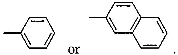

- In formula (3), R7 to R10 each independently represent a hydrogen atom; a fluorine atom; a chlorine atom; a bromine atom; an iodine atom; a C1-6 alkyl group; a C6-20 aryl group which may contain a heterocyclic atom selected from among O, N and S; a C2-6 alkenyl group; a C1-6 alkoxy group; or a C7-17 aralkyl group, and preferably, each independently represent a substituent selected from the group consisting of a hydrogen atom, a phenyl group, a naphthyl group and substituents shown below:


- Among them, preferred is a hydrogen atom,


- In formula (4), R represents a hydrogen atom or a C1-5 alkyl group, and preferably represents a hydrogen atom.

- In formula (5), A represents a C1-5 alkylene group, p is 0 or 1, K1 represents a hydrogen atom or a C1-5 alkyl group, K2 represents a hydrogen atom, a C1-5 alkyl group or a C6-20 aryl group, Z represents a carboxyl group, an alkoxycarbonyl group, a cycloalkyloxycarbonyl group, an aryloxycarbonyl group, a hydroxyalkylcarbonyl group, a glycidyloxycarbonyl group, a cyano group or an amide group, and q is 0 or 1. K2 preferably represents a hydrogen atom.
- The thermoplastic resin included in the lens part in the optical lens of the present invention preferably includes any one of the structural unit represented by formula (1), the structural unit represented by formula (2), the structural unit represented by formula (3) and the structural unit represented by formula (4). Further, it is preferred that the thermoplastic resin included in the lens part in the optical lens of the present invention includes all of the structural unit represented by formula (1), the structural unit represented by formula (2) and the structural unit represented by formula (3) because optical characteristics such as a refractive index are satisfactory in this case.
- Moreover, it is preferred that the lens part and the lens edge part in the optical lens of the present invention include the same resin because in this case, these parts have the same reflectance and as a result, light leakage characteristics and reflection characteristics are satisfactory.
- As shown in
Figure 2 , anoptical lens 20 of the second embodiment is the same as theoptical lens 10 of the first embodiment except that a lens edge part 2' includes a non-transparent region in part thereof. The shaded area in the lens edge part 2' of theoptical lens 20 is the non-transparent region. The ratio of the non-transparent region in the lens edge part 2' is not particularly limited and can be suitably adjusted. - As shown in
Figure 3 , anoptical lens 30 of the third embodiment is the same as theoptical lens 20 of the second embodiment except that the shape of a non-transparent region in a lens edge part 2' is different. The shaded area in the lens edge part 2' of theoptical lens 30 is the non-transparent region. The shape of the non-transparent region is not particularly limited and can be suitably changed. - As shown in
Figure 4 , anoptical lens 40 of the fourth embodiment is the same as theoptical lens 30 of the third embodiment except that the shape of a non-transparent region in a lens edge part 2' is different. The shaded area in the lens edge part 2' of theoptical lens 40 is the non-transparent region. The shape of the non-transparent region is not particularly limited and can be suitably changed. - As shown in
Figure 5 , anoptical lens 50 of the fifth embodiment has a lens part 1 that is an optically effective portion and has a light incidence/emission surface and a lens edge part 2' that is an optically ineffective portion and has a surface thereof except the light incidence/emission surface, the lens edge part 2' includes a non-transparent region in part thereof, and regarding the non-transparent region, the lens edge part 2' is coated with a black material. - Regarding the
optical lens 50 of the fifth embodiment, unlike the optical lenses of the first embodiment to the fourth embodiment, the lens part and the lens edge part are not required to be integrally molded. - The black material is not particularly limited as long as it can be uniformly applied to the lens edge part, and a commercially-available liquid sumi, black paint or black dye, for example, a jet-black dye NUBIAN BLACK PC-8550 manufactured by Orient Chemical Industries Co., Ltd. can be used.
- Examples of the method for coating with the black material include application, spray and immersion using the black material.
- The resin to be used for the lens part 1 of the
optical lens 50 is not particularly limited, but the resin explained with respect to theoptical lens 10 of the first embodiment can be preferably used. - As shown in
Figure 6 , anoptical lens 60 of the sixth embodiment is the same as theoptical lens 50 of the fifth embodiment except that a non-transparent region in a lens edge part 2' is obtained by carbonizing the lens edge part 2'. - Examples of the method for carbonizing the lens edge part 2' of the
optical lens 60 include a method for forming a carbide by heating, burning or the like, a method using a strong dehydration reaction with sulfuric acid or the like and a method using laser light irradiation. - The optical lens unit of the present invention comprises the optical lens of the present invention described above. The optical lens unit of the present invention is not required to comprise a spacer. For this reason, thickness reduction and size reduction can be realized, and light leakage due to reflected light at the interface can be reduced.
- According to an example of the method for producing the optical lens unit of the present invention, 4 optical lenses of the present invention are stacked and put into a barrel for optical lenses, thereby preparing the optical lens unit.
- Hereinafter, the present invention will be specifically described by way of illustrative examples, but the present invention is not limited thereto. Characteristics of optical lenses obtained were evaluated as described below.
- Light leakage in a barrel was evaluated by visual observation. The case where light leakage was not observed was rated as A, the case where almost no light leakage was observed was rated as B, the case where light leakage was slightly observed was rated as C, and the case where light leakage was significantly observed was rated as D. A and B are regarded as acceptable.
- 4 optical lenses obtained were stacked and put into a barrel for optical lenses to prepare an optical lens unit. Evaluation was made by visual observation. The case where blur of a projected character was not observed was rated as A, the case where almost no blur was observed was rated as B, the case where blur was slightly observed was rated as C, and the case where blur was significantly observed was rated as D. A and B are regarded as acceptable.
- The below-described resin A and resin B were prepared.
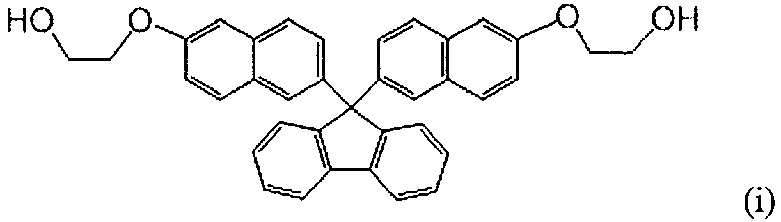
- As raw materials, 8.0 kg (14.85 mol) of 9,9-bis[6-(2-hydroxyethoxy)naphthalen-2-yl]fluorene represented by structural formula (i) below, 7.5 kg (20.03 mol) of 2,2'-bis(2-hydroxyethoxy)-1,1'-binaphthalene represented by structural formula (ii) below, 7.5 kg (12.70 mol) of 9,9-bis[4-(2-hydroxyethoxy)-3-phenylphenyl]fluorene represented by structural formula (iii) below, 10.5 kg (49.02 mol) of diphenyl carbonate and 16 ml of 2.5×10⁻² mol/l sodium hydrogen carbonate solution (4.0×10⁻⁴ mol, that is, 8.4×10⁻⁶ mol relative to 1 mol of the total of dihydroxy compounds) were put into a 50L reactor equipped with a stirrer and a distillation apparatus, and it was heated to 180°C under nitrogen atmosphere (760 mmHg). 30 minutes after the start of heating, complete dissolution of the raw materials was confirmed. After that, stirring was performed for 120 minutes under the same conditions. After that, the pressure reducing degree was adjusted to 200 mmHg, and simultaneously, the temperature was increased to 200°C at a rate of 60°C/hr. During this, the start of distillation of by-produced phenol was confirmed. After that, the temperature was kept at 200°C for 20 minutes to perform a reaction. Further, the temperature was increased to 230°C at a rate of 75°C/hr, and 10 minutes after the end of the increase of the temperature, the temperature was kept while the pressure reducing degree was adjusted to 1 mmHg or less over 2 hours. After that, the temperature was increased to 245°C at a rate of 60°C/hr, and stirring was carried out for 40 minutes. After the reaction was completed, nitrogen was introduced into the reactor to adjust the pressure to ordinary pressure, and a polycarbonate resin (resin A) produced was pelletized and taken out therefrom. Note that the obtained resin A includes all of the structural unit represented by formula (1), the structural unit represented by formula (2) and the structural unit represented by formula (3).


- 10 kg of the resin A obtained above and 100 g of a resin coloring agent (manufactured by Orient Chemical Industries Co., Ltd., trade name: NUBIAN BLACK PC-5857) as a black dye were melt-mixed using a twin screw extruder to prepare a resin B.
- The resin A and the resin B described above were respectively heated and dried at 100°C for 3 hours. After that, the resins were subjected to both insert molding and two-color molding in a manner such that the resin A was formed to be a lens part and the resin B was formed to be a lens edge part, thereby obtaining an optical lens. 4 optical lenses obtained were stacked and put into a barrel for optical lenses to prepare an optical lens unit. Physical properties of the obtained optical lens unit are shown in Table 1.
- 10 kg of the resin A obtained above and 100 g of a carbon black (MCF series #1000 manufactured by Mitsubishi Chemical Corporation) as a black pigment were melt-mixed using a twin screw extruder to prepare a resin B-1.
- Optical lenses were prepared and then an optical lens unit was prepared in a manner similar to that in Example 1, except that the resin B-1 was used instead of the resin B. Physical properties of the obtained optical lens unit are shown in Table 1.
- The below-described resin C was prepared.
- 10 kg of a polycarbonate resin (trade name: Iupilon S-3000R) manufactured by Mitsubishi Gas Chemical Company, Inc. and 100 g of a resin coloring agent (manufactured by Orient Chemical Industries Co., Ltd., trade name: NUBIAN BLACK PC-5857) as a black dye were melt-mixed using a twin screw extruder to prepare a resin C.
- Optical lenses were prepared and then an optical lens unit was prepared in a manner similar to that in Example 1, except that the resin C was used instead of the resin B. Physical properties of the obtained optical lens unit are shown in Table 1.
- Optical lenses were obtained in a manner similar to that in Example 1, except that the resin A was used instead of the resin B. 4 optical lenses obtained were stacked and put into a barrel for optical lenses to prepare an optical lens unit. Physical properties of the obtained optical lens unit are shown in Table 1. Regarding the obtained optical lenses, since the same resin A was used for the lens parts and the lens edge parts, two-color molding was not performed. Further, the lens edge parts do not include a non-transparent region in part or all thereof.
- 4 optical lenses obtained in Comparative Example 1 with a light-shielding material (trade name: SOMABLACK) manufactured by Somar Corporation being sandwiched between spacer portions of the lenses were put into a barrel for optical lenses to prepare an optical lens unit. Physical properties of the obtained optical lens unit are shown in Table 1.
Table 1 Example 1 Example 2 Example 3 Comparative Example 1 Comparative Example 2 Lens part Resin A Resin A Resin A Resin A Resin A Lens edge part Resin B Resin B-1 Resin C Resin A Resin A Spacer Absent Absent Absent Absent Present Light leakage characteristics A A B D D Resolution characteristics A A B c C - The below-described resin D was prepared.
- 23.50 kg (105.7 mol) of D-NDM represented by structural formula (a) below, wherein the mass ratio between the isomer of 2,6-position and the isomer of 2,7-position was 50:50, 22.98 kg (107.3 mol) of diphenyl carbonate and 0.13 g (1.5×10⁻³ mol) of sodium hydrogencarbonate were put into a 50L reactor equipped with a stirrer and a distillation apparatus, and it was heated to 205°C over 1 hour under nitrogen atmosphere (760 Torr) and stirred. The pressure was adjusted to 205 Torr over 30 minutes, and under conditions of 205°C and 205 Torr, the mixture was kept for 30 minutes, and a transesterification reaction was initiated. 30 minutes later, the pressure was reduced from 205 Torr to 180 Torr over 20 minutes. The temperature was increased to 215°C while reducing the pressure. The temperature was increased to reach 230°C and the pressure was reduced to be 150 Torr 120 minutes after the initiation of the reaction. The temperature was increased to reach 240°C and the pressure was reduced to be 1 Torr 180 minutes after the initiation of the reaction. After that, it was kept for 20 minutes and pelletized, thereby obtaining a polycarbonate resin (homo type of D-NDM, D-1).

- 20.0 kg (45.6 mol) of 9,9-bis[4-(2-hydroxyethoxy)phenyl]fluorene (BPEF) represented by structural formula (b) below, 10.16 kg (47.4 mol) of diphenyl carbonate and 0.03 g (3.6×10⁻⁴ mol) of sodium hydrogencarbonate were put into a 50L reactor equipped with a stirrer and a distillation apparatus, and it was heated to 205°C over 1 hour under nitrogen atmosphere (760 Torr) and stirred. The pressure was adjusted to 205 Torr over 20 minutes, and under conditions of 205°C and 205 Torr, the mixture was kept for 30 minutes, and a transesterification reaction was initiated. 30 minutes later, the pressure was reduced from 205 Torr to 180 Torr over 20 minutes. The temperature was increased to 215°C while reducing the pressure. The temperature was increased to reach 230°C and the pressure was reduced to be 150 Torr 120 minutes after the initiation of the reaction. The temperature was increased to reach 240°C and the pressure was reduced to be 1 Torr 180 minutes after the initiation of the reaction. After that, it was kept for 20 minutes and pelletized, thereby obtaining a polycarbonate resin (D-2).
- 10.0 kg of the pelletized polycarbonate resin (D-1) obtained using D-NDM as a raw material was mixed with 4.8 kg of the pelletized polycarbonate resin (D-2) obtained using BPEF as a raw material, and to the mixture, 14.8 g of a hindered phenol-based antioxidant (AO-60 manufactured by ADEKA), 4.4 g of a phosphite-based antioxidant (trade name: PEP-36) and 14.8 g of glycerin monostearate (S-100A manufactured by Riken Vitamin Co., Ltd.) as a mold release agent were added. The mixture was kneaded and pelletized using a twin screw extruder (IPEC-35), thereby obtaining a polycarbonate resin D. Note that the obtained resin D includes the aforementioned structural unit represented by formula (4).

- The below-described resin E was prepared.
- 10 kg of the resin D obtained above and 100 g of a resin coloring agent (manufactured by Orient Chemical Industries Co., Ltd., trade name: NUBIAN BLACK PC-5857) as a black dye were melt-mixed using a twin screw extruder to prepare a resin E.
- The resin D and the resin E described above were respectively heated and dried at 100°C for 3 hours. After that, the resins were subjected to both insert molding and two-color molding in a manner such that the resin D was formed to be a lens part and the resin E was formed to be a lens edge part, thereby obtaining an optical lens. 4 optical lenses obtained were stacked and put into a barrel for optical lenses to prepare an optical lens unit. Physical properties of the obtained optical lens unit are shown in Table 2.
- The below-described resin F was prepared.
- A thermoplastic resin F was obtained in a manner similar to that with respect to the resin A of Example 1, except that, as raw materials, 4.53 kg (12.1 mol) of 2,2'-bis(2-hydroxyethoxy)-1,1'-binaphthalene represented by structural formula (c) below, 8.72 kg (14.8 mol) of 9,9-bis(4-(2-hydroxyethoxy)-3-phenylphenyl)fluorene represented by structural formula (d) below, 5.99 kg (27.9 mol) of DPC and 16 ml of 2.5×10⁻² mol/l sodium hydrogen carbonate solution (4.0×10⁻⁴ mol, that is, 8.4×10⁻⁶ mol relative to 1 mol of the total of dihydroxy compounds) were used. Note that the obtained resin F includes the aforementioned structural unit represented by formula (1) and the aforementioned structural unit represented by formula (3).


- The below-described resin G was prepared.
- 10 kg of the resin F obtained above and 100 g of a resin coloring agent (manufactured by Orient Chemical Industries Co., Ltd., trade name: NUBIAN BLACK PC-5857) as a black dye were melt-mixed using a twin screw extruder to prepare a resin G.
- The resin F and the resin G described above were respectively heated and dried at 100°C for 3 hours. After that, the resins were subjected to both insert molding and two-color molding in a manner such that the resin F was formed to be a lens part and the resin G was formed to be a lens edge part, thereby obtaining an optical lens. 4 optical lenses obtained were stacked and put into a barrel for optical lenses to prepare an optical lens unit. Physical properties of the obtained optical lens unit are shown in Table 2.
Table 2 Example 4 Example 5 Lens part Resin D Resin F Lens edge part Resin E Resin G Spacer Absent Absent Light leakage characteristics A A Resolution characteristics A A - By using the optical lens of the present invention, thickness reduction and size reduction of the optical lens unit can be realized, and light leakage due to reflected light at the interface can be reduced. The present invention can be suitably used as a lens for cameras of smartphones, differential scanning calorimeters (DSCs), vehicles, etc.
-
- 1
- lens part
- 2
- lens edge part (including non-transparent region in all thereof)
- 2'
- lens edge part (including non-transparent region in part thereof)
- 10, 20, 30, 40, 50, 60
- optical lens
Claims (9)
- An optical lens formed by integrally molding a lens part that is an optically effective portion and has a light incidence/emission surface, and a lens edge part that is an optically ineffective portion and has a surface thereof except the light incidence/emission surface, wherein:the lens edge part includes a non-transparent region in part or all thereof;the lens part and the lens edge part include a thermoplastic resin; andthe non-transparent region in the lens edge part comprises 0.1 to 5% by mass in total of one or more of a black dye and a black pigment.
- The optical lens according to claim 1, wherein the thermoplastic resin included in the lens part includes at least one selected from the group consisting of: a structural unit represented by formula (1):
 R1 and R2 each independently represent a hydrogen atom; a fluorine atom; a chlorine atom; a bromine atom; an iodine atom; a C1-6 alkyl group; a C6-20 aryl group which may contain a heterocyclic atom selected from among O, N and S; a C2-6 alkenyl group; a C1-6 alkoxy group; or a C7-17 aralkyl group, anda and b each independently represent an integer of 0 to 5; a structural unit represented by formula (2):
 R3 to R6 each independently represent a hydrogen atom; a fluorine atom; a chlorine atom; a bromine atom; an iodine atom; a C1-6 alkyl group; a C6-20 aryl group which may contain a heterocyclic atom selected from among O, N and S; a C2-6 alkenyl group; a C1-6 alkoxy group; or a C7-17 aralkyl group,c and d each independently represent an integer of 0 to 6, and e and f each independently represent an integer of 0 to 4; a structural unit represented by formula (3):
 R7 to R10 each independently represent a hydrogen atom; a fluorine atom; a chlorine atom; a bromine atom; an iodine atom; a C1-6 alkyl group; a C6-20 aryl group which may contain a heterocyclic atom selected from among O, N and S; a C2-6 alkenyl group; a C1-6 alkoxy group; or a C7-17 aralkyl group, andg to j each independently represent an integer of 0 to 4; a structural unit represented by formula (4):

- The optical lens according to claim 2, wherein the thermoplastic resin included in the lens part comprises all of the structural unit represented by formula (1), the structural unit represented by formula (2) and the structural unit represented by formula (3).
- The optical lens according to any one of claims 1 to 3, wherein the lens part and the lens edge part include the same resin.
- An optical lens which comprises: a lens part that is an optically effective portion and has a light incidence/emission surface; and a lens edge part that is an optically ineffective portion and has a surface thereof except the light incidence/emission surface, wherein:the lens edge part includes a non-transparent region in part or all thereof; andthe non-transparent region in the lens edge part is obtained by coating the lens edge part with a black material or by carbonizing the lens edge part.
- The optical lens according to any one of claims 1 to 5, which is for a smartphone.
- An optical lens unit comprising the optical lens according to any one of claims 1 to 6.
- The optical lens unit according to claim 7, which does not comprise a spacer.
- A method for producing the optical lens according to any one of claims 1 to 4, which comprises integrally molding the lens part and the lens edge part using both insert molding and two-color molding.
Applications Claiming Priority (2)
| Application Number | Priority Date | Filing Date | Title |
|---|---|---|---|
| JP2018247927 | 2018-12-28 | ||
| PCT/JP2019/050451 WO2020138013A1 (en) | 2018-12-28 | 2019-12-24 | Optical lens and method for manufacturing same |
Publications (2)
| Publication Number | Publication Date |
|---|---|
| EP3904922A1 true EP3904922A1 (en) | 2021-11-03 |
| EP3904922A4 EP3904922A4 (en) | 2022-08-17 |
Family
ID=71128729
Family Applications (1)
| Application Number | Title | Priority Date | Filing Date |
|---|---|---|---|
| EP19903119.6A Pending EP3904922A4 (en) | 2018-12-28 | 2019-12-24 | OPTICAL LENS, AND METHOD FOR MAKING THE SAME |
Country Status (7)
| Country | Link |
|---|---|
| US (1) | US11960056B2 (en) |
| EP (1) | EP3904922A4 (en) |
| JP (1) | JP7484724B2 (en) |
| KR (1) | KR102935866B1 (en) |
| CN (2) | CN113227845A (en) |
| TW (1) | TWI895254B (en) |
| WO (1) | WO2020138013A1 (en) |
Cited By (1)
| Publication number | Priority date | Publication date | Assignee | Title |
|---|---|---|---|---|
| EP4442768A4 (en) * | 2021-11-30 | 2025-03-19 | Mitsubishi Gas Chemical Company, Inc. | POLYCARBONATE RESIN COMPOSITION, AND OPTICAL LENS USING SAME |
Families Citing this family (1)
| Publication number | Priority date | Publication date | Assignee | Title |
|---|---|---|---|---|
| JP7518376B2 (en) * | 2020-10-01 | 2024-07-18 | 株式会社デンソーウェーブ | Housing cover structure for security equipment |
Family Cites Families (22)
| Publication number | Priority date | Publication date | Assignee | Title |
|---|---|---|---|---|
| JP2537335B2 (en) * | 1994-06-06 | 1996-09-25 | オリンパス光学工業株式会社 | Optical head |
| DE60002526T3 (en) | 1999-07-02 | 2007-08-09 | Mitsubishi Gas Chemical Co., Inc. | Preparation of tricyclodecanedicarbaldehyde, pentacyclopentadecanedicarbaldehyde and the corresponding dimethanols |
| JP4573003B2 (en) | 1999-07-02 | 2010-11-04 | 三菱瓦斯化学株式会社 | Method for producing tricyclodecane dimethanol and / or pentacyclopentadecane dimethanol |
| JP4573002B2 (en) * | 1999-07-02 | 2010-11-04 | 三菱瓦斯化学株式会社 | Method for producing tricyclodecanedicarbaldehyde and / or pentacyclopentadecanedicarbaldehyde |
| JPWO2008096584A1 (en) * | 2007-02-07 | 2010-05-20 | コニカミノルタオプト株式会社 | Imaging device manufacturing method, imaging device, and portable terminal |
| JP2008197282A (en) * | 2007-02-09 | 2008-08-28 | Sharp Corp | Plastic lens unit, camera module, and manufacturing method thereof |
| JP2008276059A (en) | 2007-05-02 | 2008-11-13 | Canon Inc | Optical element and optical system having the same |
| US20080290435A1 (en) | 2007-05-21 | 2008-11-27 | Micron Technology, Inc. | Wafer level lens arrays for image sensor packages and the like, image sensor packages, and related methods |
| US20120134028A1 (en) | 2009-08-13 | 2012-05-31 | Fujifilm Corporation | Wafer level lens, production method of wafer level lens, and imaging unit |
| JP5263788B2 (en) * | 2009-10-22 | 2013-08-14 | シャープ株式会社 | Display device |
| JP2011164284A (en) * | 2010-02-08 | 2011-08-25 | Fujifilm Corp | Optical element unit |
| JP2012073403A (en) * | 2010-09-28 | 2012-04-12 | Fujifilm Corp | Lens unit and manufacturing method of lens unit |
| JP2013114103A (en) | 2011-11-30 | 2013-06-10 | Canon Inc | Optical system and optical equipment |
| US20160244389A1 (en) | 2013-10-25 | 2016-08-25 | Mitsubishi Gas Chemical Company, Inc. | 1,3-bis(hydroxyphenyl)-5-ethyladamantane compound and method for production thereof, and aromatic polycarbonate resin and method for production thereof |
| TW201525529A (en) | 2013-12-24 | 2015-07-01 | Forward Optics Co Ltd | Shading array lens and manufacturing method thereof |
| JP6708365B2 (en) * | 2014-03-07 | 2020-06-10 | 日鉄ケミカル&マテリアル株式会社 | Black photosensitive resin composition for light-shielding film, cured product using the same, and color filter and touch panel using the cured product as a light-shielding film |
| JP6923998B2 (en) * | 2016-03-24 | 2021-08-25 | キヤノン株式会社 | Optical member and its manufacturing method |
| JP6988805B2 (en) * | 2016-07-21 | 2022-01-05 | 三菱瓦斯化学株式会社 | Polycarbonate resin, its manufacturing method and optical lens |
| JP2018146878A (en) | 2017-03-08 | 2018-09-20 | カンタツ株式会社 | Lens element and image capturing lens unit |
| CN110461942B (en) * | 2017-03-31 | 2021-05-11 | 三菱瓦斯化学株式会社 | Polycarbonate resin composition and optical lens using the same |
| TWI735565B (en) * | 2017-04-13 | 2021-08-11 | 瑞士商愛爾康公司 | Colored contact lenses and method of making the same |
| JP6878141B2 (en) * | 2017-05-25 | 2021-05-26 | キヤノン株式会社 | Optical elements and optics |
-
2019
- 2019-12-24 WO PCT/JP2019/050451 patent/WO2020138013A1/en not_active Ceased
- 2019-12-24 EP EP19903119.6A patent/EP3904922A4/en active Pending
- 2019-12-24 US US17/416,730 patent/US11960056B2/en active Active
- 2019-12-24 JP JP2020563273A patent/JP7484724B2/en active Active
- 2019-12-24 CN CN201980084937.2A patent/CN113227845A/en active Pending
- 2019-12-24 KR KR1020217008855A patent/KR102935866B1/en active Active
- 2019-12-24 CN CN202511151290.4A patent/CN120928489A/en active Pending
- 2019-12-26 TW TW108147832A patent/TWI895254B/en active
Cited By (1)
| Publication number | Priority date | Publication date | Assignee | Title |
|---|---|---|---|---|
| EP4442768A4 (en) * | 2021-11-30 | 2025-03-19 | Mitsubishi Gas Chemical Company, Inc. | POLYCARBONATE RESIN COMPOSITION, AND OPTICAL LENS USING SAME |
Also Published As
| Publication number | Publication date |
|---|---|
| WO2020138013A1 (en) | 2020-07-02 |
| US11960056B2 (en) | 2024-04-16 |
| JP7484724B2 (en) | 2024-05-16 |
| EP3904922A4 (en) | 2022-08-17 |
| KR20210109517A (en) | 2021-09-06 |
| KR102935866B1 (en) | 2026-03-05 |
| TWI895254B (en) | 2025-09-01 |
| TW202032162A (en) | 2020-09-01 |
| CN120928489A (en) | 2025-11-11 |
| US20220043183A1 (en) | 2022-02-10 |
| JPWO2020138013A1 (en) | 2021-11-18 |
| CN113227845A (en) | 2021-08-06 |
Similar Documents
| Publication | Publication Date | Title |
|---|---|---|
| JP5273877B2 (en) | Eyeglass lenses | |
| JP6154337B2 (en) | Polycarbonate copolymer | |
| KR100711149B1 (en) | Polyester resin composition and optical material | |
| KR102255780B1 (en) | Polycarbonate resin composition, and optical material and optical lens each manufactured using same | |
| JP6812985B2 (en) | Thermoplastic resin composition and its molded article | |
| KR102478201B1 (en) | Polycarbonate resin composition and optical lens using the same | |
| CN87102261A (en) | High Refractive Index Plastic Lens Resins | |
| CN101057171A (en) | Polycarbonate resin material for molding eyeglass lenses and optical elements | |
| JP2009063976A (en) | Optical element molded article and molding material therefor | |
| CN101300286B (en) | Optical elements and chromatic aberration correction lenses | |
| KR20200105864A (en) | Polycarbonate resin composition, its manufacturing method and optical lens | |
| EP2184624A1 (en) | Lens and optical unit using the same | |
| US11960056B2 (en) | Optical lens and method for manufacturing same | |
| JP2006154783A (en) | Polycarbonate resin molding material for spectacle lenses and optical moldings | |
| JP7211705B2 (en) | Resin composition and optical lens, sheet and film containing same | |
| JP5688101B2 (en) | Optical lens made of aromatic-aliphatic polycarbonate resin | |
| WO2019240015A1 (en) | Display device and composition for display device | |
| JP5808961B2 (en) | Polycarbonate copolymer for optical lens and optical lens comprising the polycarbonate | |
| JP5080340B2 (en) | Eyeglass lenses |
Legal Events
| Date | Code | Title | Description |
|---|---|---|---|
| STAA | Information on the status of an ep patent application or granted ep patent |
Free format text: STATUS: THE INTERNATIONAL PUBLICATION HAS BEEN MADE |
|
| PUAI | Public reference made under article 153(3) epc to a published international application that has entered the european phase |
Free format text: ORIGINAL CODE: 0009012 |
|
| STAA | Information on the status of an ep patent application or granted ep patent |
Free format text: STATUS: REQUEST FOR EXAMINATION WAS MADE |
|
| 17P | Request for examination filed |
Effective date: 20210616 |
|
| AK | Designated contracting states |
Kind code of ref document: A1 Designated state(s): AL AT BE BG CH CY CZ DE DK EE ES FI FR GB GR HR HU IE IS IT LI LT LU LV MC MK MT NL NO PL PT RO RS SE SI SK SM TR |
|
| RIC1 | Information provided on ipc code assigned before grant |
Ipc: G02B 5/00 20060101ALI20220221BHEP Ipc: G02B 1/04 20060101ALI20220221BHEP Ipc: G02B 7/02 20210101ALI20220221BHEP Ipc: G02B 3/00 20060101AFI20220221BHEP |
|
| DAV | Request for validation of the european patent (deleted) | ||
| DAX | Request for extension of the european patent (deleted) | ||
| A4 | Supplementary search report drawn up and despatched |
Effective date: 20220718 |
|
| RIC1 | Information provided on ipc code assigned before grant |
Ipc: G02B 5/00 20060101ALI20220712BHEP Ipc: G02B 1/04 20060101ALI20220712BHEP Ipc: G02B 7/02 20210101ALI20220712BHEP Ipc: G02B 3/00 20060101AFI20220712BHEP |
|
| STAA | Information on the status of an ep patent application or granted ep patent |
Free format text: STATUS: EXAMINATION IS IN PROGRESS |
|
| 17Q | First examination report despatched |
Effective date: 20260420 |