EP3904882A1 - Graphene channel member comprising cadaverine olfactory receptor and sensor comprising same - Google Patents
Graphene channel member comprising cadaverine olfactory receptor and sensor comprising same Download PDFInfo
- Publication number
- EP3904882A1 EP3904882A1 EP19902534.7A EP19902534A EP3904882A1 EP 3904882 A1 EP3904882 A1 EP 3904882A1 EP 19902534 A EP19902534 A EP 19902534A EP 3904882 A1 EP3904882 A1 EP 3904882A1
- Authority
- EP
- European Patent Office
- Prior art keywords
- graphene
- group
- cadaverine
- channel member
- carbon atoms
- Prior art date
- Legal status (The legal status is an assumption and is not a legal conclusion. Google has not performed a legal analysis and makes no representation as to the accuracy of the status listed.)
- Withdrawn
Links
- OKTJSMMVPCPJKN-UHFFFAOYSA-N Carbon Chemical compound [C] OKTJSMMVPCPJKN-UHFFFAOYSA-N 0.000 title claims abstract description 201
- 229910021389 graphene Inorganic materials 0.000 title claims abstract description 180
- VHRGRCVQAFMJIZ-UHFFFAOYSA-N cadaverine Chemical compound NCCCCCN VHRGRCVQAFMJIZ-UHFFFAOYSA-N 0.000 title claims abstract description 133
- 108050002069 Olfactory receptors Proteins 0.000 title claims abstract description 38
- 102000012547 Olfactory receptors Human genes 0.000 title claims abstract description 38
- 239000000758 substrate Substances 0.000 claims abstract description 25
- 125000004432 carbon atom Chemical group C* 0.000 claims description 43
- -1 carbene compound Chemical class 0.000 claims description 38
- 239000010410 layer Substances 0.000 claims description 28
- 125000003118 aryl group Chemical group 0.000 claims description 17
- 125000000217 alkyl group Chemical group 0.000 claims description 16
- 125000001424 substituent group Chemical group 0.000 claims description 15
- 229910052739 hydrogen Inorganic materials 0.000 claims description 14
- 239000001257 hydrogen Substances 0.000 claims description 14
- 125000004435 hydrogen atom Chemical class [H]* 0.000 claims description 14
- IJGRMHOSHXDMSA-UHFFFAOYSA-N Atomic nitrogen Chemical compound N#N IJGRMHOSHXDMSA-UHFFFAOYSA-N 0.000 claims description 12
- 125000001072 heteroaryl group Chemical group 0.000 claims description 12
- 229910052799 carbon Inorganic materials 0.000 claims description 10
- 239000007789 gas Substances 0.000 claims description 10
- 239000002356 single layer Substances 0.000 claims description 10
- 125000004429 atom Chemical group 0.000 claims description 9
- 125000000753 cycloalkyl group Chemical group 0.000 claims description 9
- 239000000126 substance Substances 0.000 claims description 8
- 229910052757 nitrogen Inorganic materials 0.000 claims description 6
- 239000007791 liquid phase Substances 0.000 claims description 4
- 239000012071 phase Substances 0.000 claims description 4
- 101710102876 Trace amine-associated receptor 13c Proteins 0.000 claims description 3
- 125000001183 hydrocarbyl group Chemical group 0.000 claims 3
- 238000010521 absorption reaction Methods 0.000 claims 1
- 239000010408 film Substances 0.000 description 84
- 238000000034 method Methods 0.000 description 25
- 238000001514 detection method Methods 0.000 description 18
- 238000002360 preparation method Methods 0.000 description 15
- HZVOZRGWRWCICA-UHFFFAOYSA-N methanediyl Chemical compound [CH2] HZVOZRGWRWCICA-UHFFFAOYSA-N 0.000 description 13
- 229920003229 poly(methyl methacrylate) Polymers 0.000 description 12
- 239000004926 polymethyl methacrylate Substances 0.000 description 12
- RYGMFSIKBFXOCR-UHFFFAOYSA-N Copper Chemical compound [Cu] RYGMFSIKBFXOCR-UHFFFAOYSA-N 0.000 description 11
- 239000000463 material Substances 0.000 description 11
- FAPWRFPIFSIZLT-UHFFFAOYSA-M Sodium chloride Chemical compound [Na+].[Cl-] FAPWRFPIFSIZLT-UHFFFAOYSA-M 0.000 description 10
- 239000002041 carbon nanotube Substances 0.000 description 10
- 229910021393 carbon nanotube Inorganic materials 0.000 description 10
- 239000011889 copper foil Substances 0.000 description 10
- 238000000425 proton nuclear magnetic resonance spectrum Methods 0.000 description 10
- 230000035945 sensitivity Effects 0.000 description 10
- 108010059886 Apolipoprotein A-I Proteins 0.000 description 9
- 150000002430 hydrocarbons Chemical group 0.000 description 9
- RAXXELZNTBOGNW-UHFFFAOYSA-N imidazole Natural products C1=CNC=N1 RAXXELZNTBOGNW-UHFFFAOYSA-N 0.000 description 9
- 102000005666 Apolipoprotein A-I Human genes 0.000 description 8
- 235000013372 meat Nutrition 0.000 description 8
- 229910052751 metal Inorganic materials 0.000 description 8
- 239000002184 metal Substances 0.000 description 8
- 238000004375 physisorption Methods 0.000 description 8
- 238000005229 chemical vapour deposition Methods 0.000 description 7
- 230000000052 comparative effect Effects 0.000 description 7
- 108090000623 proteins and genes Proteins 0.000 description 7
- 239000000243 solution Substances 0.000 description 7
- QGZKDVFQNNGYKY-UHFFFAOYSA-N Ammonia Chemical compound N QGZKDVFQNNGYKY-UHFFFAOYSA-N 0.000 description 6
- YXFVVABEGXRONW-UHFFFAOYSA-N Toluene Chemical compound CC1=CC=CC=C1 YXFVVABEGXRONW-UHFFFAOYSA-N 0.000 description 6
- 235000015278 beef Nutrition 0.000 description 6
- 238000006243 chemical reaction Methods 0.000 description 6
- 230000000694 effects Effects 0.000 description 6
- DBMJMQXJHONAFJ-UHFFFAOYSA-M Sodium laurylsulphate Chemical compound [Na+].CCCCCCCCCCCCOS([O-])(=O)=O DBMJMQXJHONAFJ-UHFFFAOYSA-M 0.000 description 5
- 230000015572 biosynthetic process Effects 0.000 description 5
- 239000003054 catalyst Substances 0.000 description 5
- 230000008859 change Effects 0.000 description 5
- 238000004518 low pressure chemical vapour deposition Methods 0.000 description 5
- 238000004519 manufacturing process Methods 0.000 description 5
- 230000008569 process Effects 0.000 description 5
- 102000005962 receptors Human genes 0.000 description 5
- 108020003175 receptors Proteins 0.000 description 5
- 239000011780 sodium chloride Substances 0.000 description 5
- QKNYBSVHEMOAJP-UHFFFAOYSA-N 2-amino-2-(hydroxymethyl)propane-1,3-diol;hydron;chloride Chemical compound Cl.OCC(N)(CO)CO QKNYBSVHEMOAJP-UHFFFAOYSA-N 0.000 description 4
- KCXVZYZYPLLWCC-UHFFFAOYSA-N EDTA Chemical compound OC(=O)CN(CC(O)=O)CCN(CC(O)=O)CC(O)=O KCXVZYZYPLLWCC-UHFFFAOYSA-N 0.000 description 4
- 241000588724 Escherichia coli Species 0.000 description 4
- RDOXTESZEPMUJZ-UHFFFAOYSA-N anisole Chemical compound COC1=CC=CC=C1 RDOXTESZEPMUJZ-UHFFFAOYSA-N 0.000 description 4
- 229940125904 compound 1 Drugs 0.000 description 4
- 238000000151 deposition Methods 0.000 description 4
- PXHVJJICTQNCMI-UHFFFAOYSA-N nickel Substances [Ni] PXHVJJICTQNCMI-UHFFFAOYSA-N 0.000 description 4
- 238000000623 plasma-assisted chemical vapour deposition Methods 0.000 description 4
- 102000004169 proteins and genes Human genes 0.000 description 4
- KIDHWZJUCRJVML-UHFFFAOYSA-N putrescine Chemical compound NCCCCN KIDHWZJUCRJVML-UHFFFAOYSA-N 0.000 description 4
- 229910052710 silicon Inorganic materials 0.000 description 4
- LFQSCWFLJHTTHZ-UHFFFAOYSA-N Ethanol Chemical compound CCO LFQSCWFLJHTTHZ-UHFFFAOYSA-N 0.000 description 3
- OKKJLVBELUTLKV-UHFFFAOYSA-N Methanol Chemical compound OC OKKJLVBELUTLKV-UHFFFAOYSA-N 0.000 description 3
- VYPSYNLAJGMNEJ-UHFFFAOYSA-N Silicium dioxide Chemical compound O=[Si]=O VYPSYNLAJGMNEJ-UHFFFAOYSA-N 0.000 description 3
- XUIMIQQOPSSXEZ-UHFFFAOYSA-N Silicon Chemical compound [Si] XUIMIQQOPSSXEZ-UHFFFAOYSA-N 0.000 description 3
- 229910021529 ammonia Inorganic materials 0.000 description 3
- 125000001797 benzyl group Chemical group [H]C1=C([H])C([H])=C(C([H])=C1[H])C([H])([H])* 0.000 description 3
- 229940125782 compound 2 Drugs 0.000 description 3
- 229940126214 compound 3 Drugs 0.000 description 3
- 229940125898 compound 5 Drugs 0.000 description 3
- 229910052802 copper Inorganic materials 0.000 description 3
- 239000010949 copper Substances 0.000 description 3
- 238000011156 evaluation Methods 0.000 description 3
- 230000014509 gene expression Effects 0.000 description 3
- BPHPUYQFMNQIOC-NXRLNHOXSA-N isopropyl beta-D-thiogalactopyranoside Chemical compound CC(C)S[C@@H]1O[C@H](CO)[C@H](O)[C@H](O)[C@H]1O BPHPUYQFMNQIOC-NXRLNHOXSA-N 0.000 description 3
- 125000001449 isopropyl group Chemical group [H]C([H])([H])C([H])(*)C([H])([H])[H] 0.000 description 3
- 229910052759 nickel Inorganic materials 0.000 description 3
- 229910052760 oxygen Inorganic materials 0.000 description 3
- 239000010703 silicon Substances 0.000 description 3
- 238000000527 sonication Methods 0.000 description 3
- 238000002207 thermal evaporation Methods 0.000 description 3
- JKMHFZQWWAIEOD-UHFFFAOYSA-N 2-[4-(2-hydroxyethyl)piperazin-1-yl]ethanesulfonic acid Chemical compound OCC[NH+]1CCN(CCS([O-])(=O)=O)CC1 JKMHFZQWWAIEOD-UHFFFAOYSA-N 0.000 description 2
- BMTZEAOGFDXDAD-UHFFFAOYSA-M 4-(4,6-dimethoxy-1,3,5-triazin-2-yl)-4-methylmorpholin-4-ium;chloride Chemical compound [Cl-].COC1=NC(OC)=NC([N+]2(C)CCOCC2)=N1 BMTZEAOGFDXDAD-UHFFFAOYSA-M 0.000 description 2
- 241000252212 Danio rerio Species 0.000 description 2
- 241001200922 Gagata Species 0.000 description 2
- 239000007995 HEPES buffer Substances 0.000 description 2
- XEEYBQQBJWHFJM-UHFFFAOYSA-N Iron Chemical compound [Fe] XEEYBQQBJWHFJM-UHFFFAOYSA-N 0.000 description 2
- 239000005700 Putrescine Substances 0.000 description 2
- 229910052782 aluminium Inorganic materials 0.000 description 2
- 150000001412 amines Chemical class 0.000 description 2
- AVKUERGKIZMTKX-NJBDSQKTSA-N ampicillin Chemical compound C1([C@@H](N)C(=O)N[C@H]2[C@H]3SC([C@@H](N3C2=O)C(O)=O)(C)C)=CC=CC=C1 AVKUERGKIZMTKX-NJBDSQKTSA-N 0.000 description 2
- 229960000723 ampicillin Drugs 0.000 description 2
- 238000000137 annealing Methods 0.000 description 2
- 238000001505 atmospheric-pressure chemical vapour deposition Methods 0.000 description 2
- 238000000231 atomic layer deposition Methods 0.000 description 2
- QVGXLLKOCUKJST-UHFFFAOYSA-N atomic oxygen Chemical compound [O] QVGXLLKOCUKJST-UHFFFAOYSA-N 0.000 description 2
- 239000000872 buffer Substances 0.000 description 2
- 229940099352 cholate Drugs 0.000 description 2
- BHQCQFFYRZLCQQ-OELDTZBJSA-N cholic acid Chemical compound C([C@H]1C[C@H]2O)[C@H](O)CC[C@]1(C)[C@@H]1[C@@H]2[C@@H]2CC[C@H]([C@@H](CCC(O)=O)C)[C@@]2(C)[C@@H](O)C1 BHQCQFFYRZLCQQ-OELDTZBJSA-N 0.000 description 2
- 230000008021 deposition Effects 0.000 description 2
- 239000012153 distilled water Substances 0.000 description 2
- VHJLVAABSRFDPM-QWWZWVQMSA-N dithiothreitol Chemical compound SC[C@@H](O)[C@H](O)CS VHJLVAABSRFDPM-QWWZWVQMSA-N 0.000 description 2
- 125000000524 functional group Chemical group 0.000 description 2
- 239000012212 insulator Substances 0.000 description 2
- 150000002500 ions Chemical class 0.000 description 2
- 229910044991 metal oxide Inorganic materials 0.000 description 2
- 150000004706 metal oxides Chemical class 0.000 description 2
- UZKWTJUDCOPSNM-UHFFFAOYSA-N methoxybenzene Substances CCCCOC=C UZKWTJUDCOPSNM-UHFFFAOYSA-N 0.000 description 2
- 125000002950 monocyclic group Chemical group 0.000 description 2
- 239000002086 nanomaterial Substances 0.000 description 2
- 239000001301 oxygen Substances 0.000 description 2
- 239000008188 pellet Substances 0.000 description 2
- 125000001997 phenyl group Chemical group [H]C1=C([H])C([H])=C(*)C([H])=C1[H] 0.000 description 2
- 229920002120 photoresistant polymer Polymers 0.000 description 2
- 238000005240 physical vapour deposition Methods 0.000 description 2
- 238000009832 plasma treatment Methods 0.000 description 2
- 125000003367 polycyclic group Chemical group 0.000 description 2
- 239000000047 product Substances 0.000 description 2
- 238000000746 purification Methods 0.000 description 2
- 238000011897 real-time detection Methods 0.000 description 2
- HBMJWWWQQXIZIP-UHFFFAOYSA-N silicon carbide Chemical compound [Si+]#[C-] HBMJWWWQQXIZIP-UHFFFAOYSA-N 0.000 description 2
- 239000001488 sodium phosphate Substances 0.000 description 2
- 229910000162 sodium phosphate Inorganic materials 0.000 description 2
- ZNJHFNUEQDVFCJ-UHFFFAOYSA-M sodium;2-[4-(2-hydroxyethyl)piperazin-1-yl]ethanesulfonic acid;hydroxide Chemical compound [OH-].[Na+].OCCN1CCN(CCS(O)(=O)=O)CC1 ZNJHFNUEQDVFCJ-UHFFFAOYSA-M 0.000 description 2
- 238000004544 sputter deposition Methods 0.000 description 2
- 230000000087 stabilizing effect Effects 0.000 description 2
- 125000001973 tert-pentyl group Chemical group [H]C([H])([H])C([H])([H])C(*)(C([H])([H])[H])C([H])([H])[H] 0.000 description 2
- 125000001425 triazolyl group Chemical group 0.000 description 2
- RYFMWSXOAZQYPI-UHFFFAOYSA-K trisodium phosphate Chemical compound [Na+].[Na+].[Na+].[O-]P([O-])([O-])=O RYFMWSXOAZQYPI-UHFFFAOYSA-K 0.000 description 2
- 229910052721 tungsten Inorganic materials 0.000 description 2
- 239000013598 vector Substances 0.000 description 2
- 239000011534 wash buffer Substances 0.000 description 2
- XLYOFNOQVPJJNP-UHFFFAOYSA-N water Chemical compound O XLYOFNOQVPJJNP-UHFFFAOYSA-N 0.000 description 2
- 238000001262 western blot Methods 0.000 description 2
- 0 *C1=C(*)N(*)CN1* Chemical compound *C1=C(*)N(*)CN1* 0.000 description 1
- JYEUMXHLPRZUAT-UHFFFAOYSA-N 1,2,3-triazine Chemical group C1=CN=NN=C1 JYEUMXHLPRZUAT-UHFFFAOYSA-N 0.000 description 1
- YJTKZCDBKVTVBY-UHFFFAOYSA-N 1,3-Diphenylbenzene Chemical group C1=CC=CC=C1C1=CC=CC(C=2C=CC=CC=2)=C1 YJTKZCDBKVTVBY-UHFFFAOYSA-N 0.000 description 1
- 125000000355 1,3-benzoxazolyl group Chemical group O1C(=NC2=C1C=CC=C2)* 0.000 description 1
- FCEHBMOGCRZNNI-UHFFFAOYSA-N 1-benzothiophene Chemical group C1=CC=C2SC=CC2=C1 FCEHBMOGCRZNNI-UHFFFAOYSA-N 0.000 description 1
- 125000006218 1-ethylbutyl group Chemical group [H]C([H])([H])C([H])([H])C([H])([H])C([H])(*)C([H])([H])C([H])([H])[H] 0.000 description 1
- MYKQKWIPLZEVOW-UHFFFAOYSA-N 11h-benzo[a]carbazole Chemical group C1=CC2=CC=CC=C2C2=C1C1=CC=CC=C1N2 MYKQKWIPLZEVOW-UHFFFAOYSA-N 0.000 description 1
- 125000006176 2-ethylbutyl group Chemical group [H]C([H])([H])C([H])([H])C([H])(C([H])([H])*)C([H])([H])C([H])([H])[H] 0.000 description 1
- 125000005916 2-methylpentyl group Chemical group 0.000 description 1
- FPQQSJJWHUJYPU-UHFFFAOYSA-N 3-(dimethylamino)propyliminomethylidene-ethylazanium;chloride Chemical compound Cl.CCN=C=NCCCN(C)C FPQQSJJWHUJYPU-UHFFFAOYSA-N 0.000 description 1
- 125000004920 4-methyl-2-pentyl group Chemical group CC(CC(C)*)C 0.000 description 1
- 229910001020 Au alloy Inorganic materials 0.000 description 1
- 239000004215 Carbon black (E152) Substances 0.000 description 1
- 108020004705 Codon Proteins 0.000 description 1
- 229910000599 Cr alloy Inorganic materials 0.000 description 1
- YLQBMQCUIZJEEH-UHFFFAOYSA-N Furan Chemical group C=1C=COC=1 YLQBMQCUIZJEEH-UHFFFAOYSA-N 0.000 description 1
- 206010017577 Gait disturbance Diseases 0.000 description 1
- JMASRVWKEDWRBT-UHFFFAOYSA-N Gallium nitride Chemical compound [Ga]#N JMASRVWKEDWRBT-UHFFFAOYSA-N 0.000 description 1
- SXRSQZLOMIGNAQ-UHFFFAOYSA-N Glutaraldehyde Chemical compound O=CCCCC=O SXRSQZLOMIGNAQ-UHFFFAOYSA-N 0.000 description 1
- ZDXPYRJPNDTMRX-VKHMYHEASA-N L-glutamine Chemical compound OC(=O)[C@@H](N)CCC(N)=O ZDXPYRJPNDTMRX-VKHMYHEASA-N 0.000 description 1
- NQTADLQHYWFPDB-UHFFFAOYSA-N N-Hydroxysuccinimide Chemical compound ON1C(=O)CCC1=O NQTADLQHYWFPDB-UHFFFAOYSA-N 0.000 description 1
- 229910000577 Silicon-germanium Inorganic materials 0.000 description 1
- FZWLAAWBMGSTSO-UHFFFAOYSA-N Thiazole Chemical group C1=CSC=N1 FZWLAAWBMGSTSO-UHFFFAOYSA-N 0.000 description 1
- YTPLMLYBLZKORZ-UHFFFAOYSA-N Thiophene Chemical group C=1C=CSC=1 YTPLMLYBLZKORZ-UHFFFAOYSA-N 0.000 description 1
- LEVVHYCKPQWKOP-UHFFFAOYSA-N [Si].[Ge] Chemical compound [Si].[Ge] LEVVHYCKPQWKOP-UHFFFAOYSA-N 0.000 description 1
- 125000001931 aliphatic group Chemical group 0.000 description 1
- XAGFODPZIPBFFR-UHFFFAOYSA-N aluminium Chemical compound [Al] XAGFODPZIPBFFR-UHFFFAOYSA-N 0.000 description 1
- 125000002178 anthracenyl group Chemical group C1(=CC=CC2=CC3=CC=CC=C3C=C12)* 0.000 description 1
- 229910052787 antimony Inorganic materials 0.000 description 1
- 238000013459 approach Methods 0.000 description 1
- 150000001540 azides Chemical class 0.000 description 1
- 125000003785 benzimidazolyl group Chemical group N1=C(NC2=C1C=CC=C2)* 0.000 description 1
- 125000000499 benzofuranyl group Chemical group O1C(=CC2=C1C=CC=C2)* 0.000 description 1
- IOJUPLGTWVMSFF-UHFFFAOYSA-N benzothiazole Chemical group C1=CC=C2SC=NC2=C1 IOJUPLGTWVMSFF-UHFFFAOYSA-N 0.000 description 1
- 229910052790 beryllium Inorganic materials 0.000 description 1
- 125000006267 biphenyl group Chemical group 0.000 description 1
- 229910052797 bismuth Inorganic materials 0.000 description 1
- 230000000903 blocking effect Effects 0.000 description 1
- 239000007853 buffer solution Substances 0.000 description 1
- 125000000484 butyl group Chemical group [H]C([*])([H])C([H])([H])C([H])([H])C([H])([H])[H] 0.000 description 1
- 125000000609 carbazolyl group Chemical group C1(=CC=CC=2C3=CC=CC=C3NC12)* 0.000 description 1
- 239000007833 carbon precursor Substances 0.000 description 1
- 239000013592 cell lysate Substances 0.000 description 1
- 238000005119 centrifugation Methods 0.000 description 1
- 239000002800 charge carrier Substances 0.000 description 1
- 229910052804 chromium Inorganic materials 0.000 description 1
- 125000002676 chrysenyl group Chemical group C1(=CC=CC=2C3=CC=C4C=CC=CC4=C3C=CC12)* 0.000 description 1
- 238000010367 cloning Methods 0.000 description 1
- 239000002299 complementary DNA Substances 0.000 description 1
- 239000000470 constituent Substances 0.000 description 1
- 239000007822 coupling agent Substances 0.000 description 1
- 239000013078 crystal Substances 0.000 description 1
- 238000002425 crystallisation Methods 0.000 description 1
- 230000008025 crystallization Effects 0.000 description 1
- 125000001995 cyclobutyl group Chemical group [H]C1([H])C([H])([H])C([H])(*)C1([H])[H] 0.000 description 1
- 125000000582 cycloheptyl group Chemical group [H]C1([H])C([H])([H])C([H])([H])C([H])([H])C([H])(*)C([H])([H])C1([H])[H] 0.000 description 1
- 125000000113 cyclohexyl group Chemical group [H]C1([H])C([H])([H])C([H])([H])C([H])(*)C([H])([H])C1([H])[H] 0.000 description 1
- 125000004210 cyclohexylmethyl group Chemical group [H]C([H])(*)C1([H])C([H])([H])C([H])([H])C([H])([H])C([H])([H])C1([H])[H] 0.000 description 1
- 125000000640 cyclooctyl group Chemical group [H]C1([H])C([H])([H])C([H])([H])C([H])([H])C([H])(*)C([H])([H])C([H])([H])C1([H])[H] 0.000 description 1
- 125000001511 cyclopentyl group Chemical group [H]C1([H])C([H])([H])C([H])([H])C([H])(*)C1([H])[H] 0.000 description 1
- 125000004851 cyclopentylmethyl group Chemical group C1(CCCC1)C* 0.000 description 1
- 125000001559 cyclopropyl group Chemical group [H]C1([H])C([H])([H])C1([H])* 0.000 description 1
- 230000007547 defect Effects 0.000 description 1
- 230000000593 degrading effect Effects 0.000 description 1
- 238000011033 desalting Methods 0.000 description 1
- 238000013461 design Methods 0.000 description 1
- 238000010586 diagram Methods 0.000 description 1
- 238000000502 dialysis Methods 0.000 description 1
- IYYZUPMFVPLQIF-ALWQSETLSA-N dibenzothiophene Chemical group C1=CC=CC=2[34S]C3=C(C=21)C=CC=C3 IYYZUPMFVPLQIF-ALWQSETLSA-N 0.000 description 1
- 230000005684 electric field Effects 0.000 description 1
- 230000005685 electric field effect Effects 0.000 description 1
- 238000005566 electron beam evaporation Methods 0.000 description 1
- 238000005530 etching Methods 0.000 description 1
- 125000001495 ethyl group Chemical group [H]C([H])([H])C([H])([H])* 0.000 description 1
- 238000002474 experimental method Methods 0.000 description 1
- 239000013604 expression vector Substances 0.000 description 1
- 238000001914 filtration Methods 0.000 description 1
- 125000003983 fluorenyl group Chemical group C1(=CC=CC=2C3=CC=CC=C3CC12)* 0.000 description 1
- 235000013305 food Nutrition 0.000 description 1
- 238000012215 gene cloning Methods 0.000 description 1
- 239000011521 glass Substances 0.000 description 1
- ZDXPYRJPNDTMRX-UHFFFAOYSA-N glutamine Natural products OC(=O)C(N)CCC(N)=O ZDXPYRJPNDTMRX-UHFFFAOYSA-N 0.000 description 1
- 229910002804 graphite Inorganic materials 0.000 description 1
- 239000010439 graphite Substances 0.000 description 1
- 238000010438 heat treatment Methods 0.000 description 1
- 125000003187 heptyl group Chemical group [H]C([*])([H])C([H])([H])C([H])([H])C([H])([H])C([H])([H])C([H])([H])C([H])([H])[H] 0.000 description 1
- 125000005842 heteroatom Chemical group 0.000 description 1
- 125000004051 hexyl group Chemical group [H]C([H])([H])C([H])([H])C([H])([H])C([H])([H])C([H])([H])C([H])([H])* 0.000 description 1
- 229930195733 hydrocarbon Natural products 0.000 description 1
- 125000002883 imidazolyl group Chemical group 0.000 description 1
- 230000003100 immobilizing effect Effects 0.000 description 1
- 238000011534 incubation Methods 0.000 description 1
- 229910052738 indium Inorganic materials 0.000 description 1
- 125000001041 indolyl group Chemical group 0.000 description 1
- 229910052742 iron Inorganic materials 0.000 description 1
- 125000000959 isobutyl group Chemical group [H]C([H])([H])C([H])(C([H])([H])[H])C([H])([H])* 0.000 description 1
- 125000004491 isohexyl group Chemical group C(CCC(C)C)* 0.000 description 1
- 125000001972 isopentyl group Chemical group [H]C([H])([H])C([H])(C([H])([H])[H])C([H])([H])C([H])([H])* 0.000 description 1
- 125000002183 isoquinolinyl group Chemical group C1(=NC=CC2=CC=CC=C12)* 0.000 description 1
- 229910052745 lead Inorganic materials 0.000 description 1
- 239000012139 lysis buffer Substances 0.000 description 1
- 229910052748 manganese Inorganic materials 0.000 description 1
- 238000005259 measurement Methods 0.000 description 1
- 229910001092 metal group alloy Inorganic materials 0.000 description 1
- 125000002496 methyl group Chemical group [H]C([H])([H])* 0.000 description 1
- 239000000203 mixture Substances 0.000 description 1
- 238000012544 monitoring process Methods 0.000 description 1
- 125000004108 n-butyl group Chemical group [H]C([H])([H])C([H])([H])C([H])([H])C([H])([H])* 0.000 description 1
- 125000003136 n-heptyl group Chemical group [H]C([H])([H])C([H])([H])C([H])([H])C([H])([H])C([H])([H])C([H])([H])C([H])([H])* 0.000 description 1
- 125000001280 n-hexyl group Chemical group C(CCCCC)* 0.000 description 1
- 125000000740 n-pentyl group Chemical group [H]C([H])([H])C([H])([H])C([H])([H])C([H])([H])C([H])([H])* 0.000 description 1
- 125000004123 n-propyl group Chemical group [H]C([H])([H])C([H])([H])C([H])([H])* 0.000 description 1
- 125000001624 naphthyl group Chemical group 0.000 description 1
- 125000001971 neopentyl group Chemical group [H]C([*])([H])C(C([H])([H])[H])(C([H])([H])[H])C([H])([H])[H] 0.000 description 1
- 229910052758 niobium Inorganic materials 0.000 description 1
- 150000004767 nitrides Chemical class 0.000 description 1
- 125000002347 octyl group Chemical group [H]C([*])([H])C([H])([H])C([H])([H])C([H])([H])C([H])([H])C([H])([H])C([H])([H])C([H])([H])[H] 0.000 description 1
- 230000002018 overexpression Effects 0.000 description 1
- WCPAKWJPBJAGKN-UHFFFAOYSA-N oxadiazole Chemical group C1=CON=N1 WCPAKWJPBJAGKN-UHFFFAOYSA-N 0.000 description 1
- 125000002971 oxazolyl group Chemical group 0.000 description 1
- 230000033116 oxidation-reduction process Effects 0.000 description 1
- 229910052763 palladium Inorganic materials 0.000 description 1
- 238000000059 patterning Methods 0.000 description 1
- 125000003538 pentan-3-yl group Chemical group [H]C([H])([H])C([H])([H])C([H])(*)C([H])([H])C([H])([H])[H] 0.000 description 1
- 125000001147 pentyl group Chemical group C(CCCC)* 0.000 description 1
- 125000002080 perylenyl group Chemical group C1(=CC=C2C=CC=C3C4=CC=CC5=CC=CC(C1=C23)=C45)* 0.000 description 1
- 125000005561 phenanthryl group Chemical group 0.000 description 1
- 229910052698 phosphorus Inorganic materials 0.000 description 1
- 238000000206 photolithography Methods 0.000 description 1
- 125000004592 phthalazinyl group Chemical group C1(=NN=CC2=CC=CC=C12)* 0.000 description 1
- XKJCHHZQLQNZHY-UHFFFAOYSA-N phthalimide Chemical compound C1=CC=C2C(=O)NC(=O)C2=C1 XKJCHHZQLQNZHY-UHFFFAOYSA-N 0.000 description 1
- 229920003023 plastic Polymers 0.000 description 1
- 239000004033 plastic Substances 0.000 description 1
- 229910052697 platinum Inorganic materials 0.000 description 1
- 125000001436 propyl group Chemical group [H]C([*])([H])C([H])([H])C([H])([H])[H] 0.000 description 1
- 125000001725 pyrenyl group Chemical group 0.000 description 1
- 125000004076 pyridyl group Chemical group 0.000 description 1
- 125000000714 pyrimidinyl group Chemical group 0.000 description 1
- 125000000168 pyrrolyl group Chemical group 0.000 description 1
- 125000002294 quinazolinyl group Chemical group N1=C(N=CC2=CC=CC=C12)* 0.000 description 1
- 125000002943 quinolinyl group Chemical group N1=C(C=CC2=CC=CC=C12)* 0.000 description 1
- 125000001567 quinoxalinyl group Chemical group N1=C(C=NC2=CC=CC=C12)* 0.000 description 1
- 230000009257 reactivity Effects 0.000 description 1
- 230000009467 reduction Effects 0.000 description 1
- 238000011160 research Methods 0.000 description 1
- 229910052702 rhenium Inorganic materials 0.000 description 1
- 229910052703 rhodium Inorganic materials 0.000 description 1
- 125000002914 sec-butyl group Chemical group [H]C([H])([H])C([H])([H])C([H])(*)C([H])([H])[H] 0.000 description 1
- 125000003548 sec-pentyl group Chemical group [H]C([H])([H])C([H])([H])C([H])([H])C([H])(*)C([H])([H])[H] 0.000 description 1
- 229910052711 selenium Inorganic materials 0.000 description 1
- 239000004065 semiconductor Substances 0.000 description 1
- 238000000926 separation method Methods 0.000 description 1
- 229910010271 silicon carbide Inorganic materials 0.000 description 1
- 229910052814 silicon oxide Inorganic materials 0.000 description 1
- 229910052709 silver Inorganic materials 0.000 description 1
- 150000003384 small molecules Chemical class 0.000 description 1
- 238000002415 sodium dodecyl sulfate polyacrylamide gel electrophoresis Methods 0.000 description 1
- 239000012064 sodium phosphate buffer Substances 0.000 description 1
- 239000011537 solubilization buffer Substances 0.000 description 1
- 239000002904 solvent Substances 0.000 description 1
- 238000010186 staining Methods 0.000 description 1
- 229910052717 sulfur Inorganic materials 0.000 description 1
- 239000006228 supernatant Substances 0.000 description 1
- 238000010189 synthetic method Methods 0.000 description 1
- 239000013077 target material Substances 0.000 description 1
- 125000000999 tert-butyl group Chemical group [H]C([H])([H])C(*)(C([H])([H])[H])C([H])([H])[H] 0.000 description 1
- DZLFLBLQUQXARW-UHFFFAOYSA-N tetrabutylammonium Chemical class CCCC[N+](CCCC)(CCCC)CCCC DZLFLBLQUQXARW-UHFFFAOYSA-N 0.000 description 1
- 239000010409 thin film Substances 0.000 description 1
- 229910052719 titanium Inorganic materials 0.000 description 1
- 125000005580 triphenylene group Chemical group 0.000 description 1
- 229910052720 vanadium Inorganic materials 0.000 description 1
- 229910052725 zinc Inorganic materials 0.000 description 1
- 229910052726 zirconium Inorganic materials 0.000 description 1
Images


Classifications
-
- G—PHYSICS
- G01—MEASURING; TESTING
- G01N—INVESTIGATING OR ANALYSING MATERIALS BY DETERMINING THEIR CHEMICAL OR PHYSICAL PROPERTIES
- G01N33/00—Investigating or analysing materials by specific methods not covered by groups G01N1/00 - G01N31/00
- G01N33/48—Biological material, e.g. blood, urine; Haemocytometers
- G01N33/50—Chemical analysis of biological material, e.g. blood, urine; Testing involving biospecific ligand binding methods; Immunological testing
- G01N33/68—Chemical analysis of biological material, e.g. blood, urine; Testing involving biospecific ligand binding methods; Immunological testing involving proteins, peptides or amino acids
- G01N33/6872—Intracellular protein regulatory factors and their receptors, e.g. including ion channels
-
- G—PHYSICS
- G01—MEASURING; TESTING
- G01N—INVESTIGATING OR ANALYSING MATERIALS BY DETERMINING THEIR CHEMICAL OR PHYSICAL PROPERTIES
- G01N27/00—Investigating or analysing materials by the use of electric, electrochemical, or magnetic means
- G01N27/26—Investigating or analysing materials by the use of electric, electrochemical, or magnetic means by investigating electrochemical variables; by using electrolysis or electrophoresis
- G01N27/403—Cells and electrode assemblies
- G01N27/414—Ion-sensitive or chemical field-effect transistors, i.e. ISFETS or CHEMFETS
- G01N27/4145—Ion-sensitive or chemical field-effect transistors, i.e. ISFETS or CHEMFETS specially adapted for biomolecules, e.g. gate electrode with immobilised receptors
-
- G—PHYSICS
- G01—MEASURING; TESTING
- G01N—INVESTIGATING OR ANALYSING MATERIALS BY DETERMINING THEIR CHEMICAL OR PHYSICAL PROPERTIES
- G01N27/00—Investigating or analysing materials by the use of electric, electrochemical, or magnetic means
- G01N27/26—Investigating or analysing materials by the use of electric, electrochemical, or magnetic means by investigating electrochemical variables; by using electrolysis or electrophoresis
- G01N27/28—Electrolytic cell components
- G01N27/30—Electrodes, e.g. test electrodes; Half-cells
- G01N27/308—Electrodes, e.g. test electrodes; Half-cells at least partially made of carbon
-
- G—PHYSICS
- G01—MEASURING; TESTING
- G01N—INVESTIGATING OR ANALYSING MATERIALS BY DETERMINING THEIR CHEMICAL OR PHYSICAL PROPERTIES
- G01N27/00—Investigating or analysing materials by the use of electric, electrochemical, or magnetic means
- G01N27/26—Investigating or analysing materials by the use of electric, electrochemical, or magnetic means by investigating electrochemical variables; by using electrolysis or electrophoresis
- G01N27/403—Cells and electrode assemblies
- G01N27/406—Cells and probes with solid electrolytes
- G01N27/407—Cells and probes with solid electrolytes for investigating or analysing gases
-
- G—PHYSICS
- G01—MEASURING; TESTING
- G01N—INVESTIGATING OR ANALYSING MATERIALS BY DETERMINING THEIR CHEMICAL OR PHYSICAL PROPERTIES
- G01N27/00—Investigating or analysing materials by the use of electric, electrochemical, or magnetic means
- G01N27/26—Investigating or analysing materials by the use of electric, electrochemical, or magnetic means by investigating electrochemical variables; by using electrolysis or electrophoresis
- G01N27/403—Cells and electrode assemblies
- G01N27/414—Ion-sensitive or chemical field-effect transistors, i.e. ISFETS or CHEMFETS
- G01N27/4146—Ion-sensitive or chemical field-effect transistors, i.e. ISFETS or CHEMFETS involving nanosized elements, e.g. nanotubes, nanowires
-
- G—PHYSICS
- G01—MEASURING; TESTING
- G01N—INVESTIGATING OR ANALYSING MATERIALS BY DETERMINING THEIR CHEMICAL OR PHYSICAL PROPERTIES
- G01N33/00—Investigating or analysing materials by specific methods not covered by groups G01N1/00 - G01N31/00
- G01N33/02—Food
- G01N33/12—Meat; Fish
-
- G—PHYSICS
- G01—MEASURING; TESTING
- G01N—INVESTIGATING OR ANALYSING MATERIALS BY DETERMINING THEIR CHEMICAL OR PHYSICAL PROPERTIES
- G01N33/00—Investigating or analysing materials by specific methods not covered by groups G01N1/00 - G01N31/00
- G01N33/48—Biological material, e.g. blood, urine; Haemocytometers
- G01N33/50—Chemical analysis of biological material, e.g. blood, urine; Testing involving biospecific ligand binding methods; Immunological testing
- G01N33/53—Immunoassay; Biospecific binding assay; Materials therefor
- G01N33/5308—Immunoassay; Biospecific binding assay; Materials therefor for analytes not provided for elsewhere, e.g. nucleic acids, uric acid, worms, mites
-
- G—PHYSICS
- G01—MEASURING; TESTING
- G01N—INVESTIGATING OR ANALYSING MATERIALS BY DETERMINING THEIR CHEMICAL OR PHYSICAL PROPERTIES
- G01N33/00—Investigating or analysing materials by specific methods not covered by groups G01N1/00 - G01N31/00
- G01N33/48—Biological material, e.g. blood, urine; Haemocytometers
- G01N33/50—Chemical analysis of biological material, e.g. blood, urine; Testing involving biospecific ligand binding methods; Immunological testing
- G01N33/53—Immunoassay; Biospecific binding assay; Materials therefor
- G01N33/543—Immunoassay; Biospecific binding assay; Materials therefor with an insoluble carrier for immobilising immunochemicals
- G01N33/54353—Immunoassay; Biospecific binding assay; Materials therefor with an insoluble carrier for immobilising immunochemicals with ligand attached to the carrier via a chemical coupling agent
-
- G—PHYSICS
- G01—MEASURING; TESTING
- G01N—INVESTIGATING OR ANALYSING MATERIALS BY DETERMINING THEIR CHEMICAL OR PHYSICAL PROPERTIES
- G01N33/00—Investigating or analysing materials by specific methods not covered by groups G01N1/00 - G01N31/00
- G01N33/48—Biological material, e.g. blood, urine; Haemocytometers
- G01N33/50—Chemical analysis of biological material, e.g. blood, urine; Testing involving biospecific ligand binding methods; Immunological testing
- G01N33/53—Immunoassay; Biospecific binding assay; Materials therefor
- G01N33/543—Immunoassay; Biospecific binding assay; Materials therefor with an insoluble carrier for immobilising immunochemicals
- G01N33/54366—Apparatus specially adapted for solid-phase testing
- G01N33/54373—Apparatus specially adapted for solid-phase testing involving physiochemical end-point determination, e.g. wave-guides, FETS, gratings
- G01N33/5438—Electrodes
-
- B—PERFORMING OPERATIONS; TRANSPORTING
- B82—NANOTECHNOLOGY
- B82Y—SPECIFIC USES OR APPLICATIONS OF NANOSTRUCTURES; MEASUREMENT OR ANALYSIS OF NANOSTRUCTURES; MANUFACTURE OR TREATMENT OF NANOSTRUCTURES
- B82Y30/00—Nanotechnology for materials or surface science, e.g. nanocomposites
Definitions
- the present invention relates to a graphene channel member comprising a cadaverine olfactory receptor and a sensor comprising same.
- the conventional discrimination platform of meat freshness is a method of monitoring the change of electric resistance by physisorption based on a metal oxide thin film or a nano material, which has a suitable structure for detecting small molecules (hydrogen, ethanol, ammonia, methanol, toluene, or the like), but there are current limits as follows.
- the conventional precedent research for detecting cadaverine has been reported carbon nanotubes combined with cadaverine receptors by the present team of researchers for the first time ( Park, Taehyeon, et al., ACS Nano, 2017, 11, 11847-11855 ).
- the detection limit by the carbon nanotubes is 10 pM, but an amount of the carbon nanotubes mounted on an electrode is not constant, and insufficient reproducibility of experimental results became a stumbling block in the way of commercialization. Accordingly, in order to overcome such problems, a next-generation nano material capable of replacing the carbon nanotube is required as it is.
- the present invention is made to overcome the above-described limits of the conventional detector for meat freshness, and provides a sensor having reproducibility and high sensitivity by using a graphene channel member including a graphene film and a cadaverine olfactory receptor (Taar13c) immobilized to the graphene film.
- a graphene channel member including a graphene film and a cadaverine olfactory receptor (Taar13c) immobilized to the graphene film.
- the present invention provides a graphene channel member comprising a graphene film and a cadaverine olfactory receptor immobilized to the graphene film.
- the present invention provides a graphene transistor comprising: a substrate; the graphene channel member; and a pair of electrodes.
- the present invention provides a bio sensor comprising the graphene transistor.
- the detection limit of cadaverine produced during the decay of meat may be improved, and effects of detecting with high sensitivity and reproducibility may be achieved.
- the graphene transistor including the graphene channel member of the present invention may be manufactured in a USIM chip type and applied in a miniaturized bio sensor (portable electronic gas sensor, or the like), and effects of very simply and accurately discriminating the freshness of meat may be achieved.
- the present invention provides a graphene channel member including a graphene film and a cadaverine olfactory receptor immobilized to the graphene film.
- the cadaverine olfactory receptor may react with liquid phase cadaverine and/or gas phase cadaverine.
- the cadaverine olfactory receptor may include a trace amine-associated receptor 13c (Taar13c).
- Taar13c is one of a receptor related to a trace amount of amine of zebrafish and reacts very sensitively to cadaverine.
- the cadaverine olfactory receptor may have an immobilized type to the surface of the graphene film by a physical bond, or may have an immobilized type by a chemical bond.
- the immobilization of the cadaverine olfactory receptor to the surface of the graphene film by a physical bond may be immobilization through physisorption.
- the cadaverine olfactory receptor may be immobilized to the surface of the graphene film through physisorption without a separate linker.
- the cadaverine olfactory receptor may be immobilized by a physisorption method of reacting at temperature conditions of about 1 to 10°C for 12 to 48 hours.
- the immobilization of the cadaverine olfactory receptor to the surface of the graphene film by a chemical bond may be bonding (immobilization) by including a carbene compound represented by Formula 1 or Formula 2 below as a linker. That is, the carbene compound may play the role of a medium for chemically immobilizing the cadaverine olfactory to the graphene film.
- a carbene compound represented by Formula 1 or Formula 2 below as a linker.
- At least one of R1 and R2 and at least one of R5 and R6 may be the same or different, and may be each independently an alkyl group of 1 to 20 carbon atoms or an aryl group of 6 to 30 carbon atoms.
- At least one of R1 and R2 and at least one of R5 and R6 may be the same or different, and may be each independently isopropyl or benzyl.
- R3, R4, R7, R8, R9 and R10 may be the same or different, and may be each independently hydrogen, an alkyl group of 1 to 20 carbon atoms, a cycloalkyl group of 3 to 20 carbon atoms, an aryl group of 6 to 30 carbon atoms, a heteroaryl group of 2 to 30 carbon atoms or a structure represented by Formula 3, or two or more adjacent substituents among R7 to R10 may be combined to form a hydrocarbon ring.
- R3, R4, R7, R8, R9 and R10 may be the same or different, and may be each independently hydrogen, or a structure represented by Formula 3, or two or more adjacent substituents among R7 to R10 may be combined to form a hydrocarbon ring.
- At least one hydrogen which is bonded to carbon forming the hydrocarbon ring may be substituted with a structure represented by Formula 3.
- At least one of R3 and R4 may have the structure represented by Formula 3.
- at least one of R7 to R10 may have the structure represented by Formula 3.
- n is a repeating number in the parenthesis and may be an integer of 1 to 30, preferably, 1 to 10. More preferably, n may be 1 to 3.
- the A may be an alkyl group of 1 to 20 carbon atoms, including a nitrogen (N) atom, or a heteroaryl group of 2 to 30 carbon atoms, including a nitrogen (N) atom.
- the A may be azide, phthalimide, or amine.
- an "adjacent" group may mean a substituent substituted at an atom which is directly connected with an atom at which a corresponding substituent is substituted, a substituent sterically at the nearest position to a corresponding substituent, or another substituent substituted at an atom at which a corresponding substituent is substituted.
- two substituents substituted at ortho positions in a benzene ring, and two substituents substituted at the same carbon in an aliphatic ring may be interpreted as "adjacent" groups to each other.
- the alkyl group may be a linear chain or a branched chain, and may have 1 to 20 carbon atoms, preferably, 1 to 10 carbon atoms. More preferably, the carbon number may be 1 to 6.
- Particular examples of the alkyl group may include a methyl group, an ethyl group, a propyl group, an n-propyl group, an isopropyl group, a butyl group, an n-butyl group, an isobutyl group, a tert-butyl group, a sec-butyl group, an 1-methylbutyl group, an 1-ethylbutyl group, a pentyl group, an n-pentyl group, an isopentyl group, a neopentyl group, a tert-pentyl group, a hexyl group, an n-hexyl group, an 1-methylpentyl group, a 2-methylpentyl group,
- the cycloalkyl group may have 3 to 20 carbon atoms, preferably, 3 to 10 carbon atoms.
- Particular examples of the cycloalkyl group may include a cyclopropyl group, a cyclobutyl group, a cyclopentyl group, a 3-methylcyclopentyl group, a 2,3-dimethylcyclopentyl group, a cyclohexyl group, a 3-methylcyclohexyl group, a 4-methylcyclohexyl group, a 2,3-dimethylcyclohexyl group, a 3,4,5-trimethylcyclohexyl group, a 4-tert-butylcyclohexyl group, a cycloheptyl group or a cyclooctyl group, without limitation.
- the aryl group may have 6 to 30 carbon atoms, preferably, 6 to 10 carbon atoms.
- the aryl group may be a monocyclic aryl group or a polycyclic aryl group.
- Particular examples of the monocyclic aryl group may include a phenyl group, a biphenyl group or a terphenyl group
- particular examples of the polycyclic aryl group may include a naphthyl group, an anthracenyl group, a phenanthryl group, a pyrenyl group, a perylenyl group, a chrysenyl group, a fluorenyl group, or a triphenylene group, without limitation.
- the heteroaryl group may be an aromatic ring group including one or more selected from N, O, P, S, Si and Se as a heteroatom and having 2 to 30 carbon atoms, preferably, 2 to 20 carbon atoms.
- Particular examples of the heteroaryl group may include a thiophene group, a furan group, a pyrrole group, an imidazole group, a thiazole group, an oxazole group, an oxadiazole group, a triazole group, a pyridyl group, a pyrimidyl group, a triazine group, a triazole group, an acridyl group, a quinolinyl group, a quinazoline group, a quinoxalinyl group, a phthalazinyl group, an isoquinoline group, an indole group, a carbazole group, a benzoxazole group, a benzimidazole group, a benzo
- alkyl group, cycloalkyl group, aryl group, heteroaryl group or hydrocarbon ring may be further substituted or unsubstituted with an alkyl group, cycloalkyl group, aryl group or heteroaryl group.
- a temperature of 100°C or higher may be applied so that unshared electron pair of the carbene compound may make a chemical bond (covalent bond) with the graphene film.
- the cadaverine olfactory receptor may be chemically bonded to the carbene compound, for example, a functional group at the terminal group of the carbene compound and the functional group of the cadaverine olfactory receptor may make chemical bond by a coupling agent (for example, 4-(4,6-dimethoxy-1,3,5-triazin-2-yl)-4-methylmorpholinium tetrafluoroborate (DMTMM), N-(3-dimethylaminopropyl)-N'-ethylcarbodiimide hydrochloride and N-hydroxysuccinimide (EDC-NHS), glutaraldehyde, or the like).
- a coupling agent for example, 4-(4,6-dimethoxy-1,3,5-triazin-2-yl)-4-methylmorpholinium tetrafluoroborate (DMTMM), N-(3-dimethylaminopropyl)-N'-ethylcarbodiimide hydrochloride and
- a sensor using after combining the conventional cadaverine receptor and carbon nanotube had a detection limit of 10 pM, and the amount of carbon nanotubes mounted on an electrode was not constant, and accordingly, there were problems in reproducibility of the experimental results of a graphene transistor.
- a cadaverine olfactory receptor is physically or chemically bonded to a graphene film having high charge mobility, and improved detection efficiency by about 1,000 times or more, particularly, 10,000 times or more, more particularly, 100,000 times or more than a carbon nanotube-based sensor, may be shown, and there are advantages in having a detection limit of 0.1 fM which is further sensitive sensor performance than a case of using the conventional carbon nanotube, and detecting gas phase cadaverine as well as liquid phase cadaverine simultaneously.
- the graphene film may have a single layer or a bi-layer. If a graphene film with a bi-layer is used, the sensitivity of a graphene transistor may be degraded due to the reduction of surface resistance, and in this regard, a graphene film with a single layer is preferably included.
- the graphene film may be patterned, particularly, minutely patterned.
- the cadaverine olfactory receptor On the surface of the patterned graphene film, the cadaverine olfactory receptor may be bonded (immobilized).
- the graphene film may be patterned into diverse shapes such as a circle, triangle, square, pentagon, and hexagon (honeycomb).
- patterns of the graphene film with various shapes may be provided, a bio sensor may be miniaturized and easy to carry, and requirement on the design with various shapes of a graphene transistor may be met.
- the cadaverine olfactory receptor On the surface of the patterned graphene film, the cadaverine olfactory receptor may be bonded.
- the cadaverine olfactory receptor may be immobilized to the surface of the graphene film by a physical bond through physisorption, or may be immobilized to the graphene film by a chemical bond through the carbene compound represented by Formula 1 or Formula 2 as a linker.
- the graphene channel member includes the graphene film, and in case of using graphene as such a channel member, high current flows in an off state when a voltage is not applied to a gate, the on/off ratio of an operation current is very low, and there are advantages in manufacturing a transistor having high performance.
- the thickness of the graphene film may be 0.1 to 1 nm, and this may mean the thickness of a graphene film having a single layer. If the thickness of the graphene film satisfies the above-described range, the properties of high conductivity and high charge mobility may be shown, and a graphene transistor with high sensitivity may be manufactured.
- the present invention provides a graphene transistor including the graphene channel member.
- the graphene transistor of the present invention includes: a substrate; the above-described graphene channel member; and a pair of electrodes.
- the substrate plays the role of a support for supporting the constituents of the graphene transistor of the present invention and may use an insulating inorganic substrate including a Si substrate, a glass substrate, a GaN substrate, a silica (SiO 2 ) substrate, or the like, a metal substrate including Ni, Cu, W, or the like, or a plastic substrate.
- the silica (SiO 2 ) substrate, or a silicon wafer is preferable in regard of excellent affinity with the graphene channel member.
- the substrate may be selected from diverse materials on which the deposition of graphene is possible, for example, may be composed of a material including silicon-germanium, silicon carbide (SiC), or the like, and may include an epitaxial layer, a silicon-on-insulator layer, a semiconductor-on-insulator layer, or the like.
- SiC silicon carbide
- the graphene channel member may be formed on the substrate.
- a graphene film may be formed by growing graphene on the substrate by a chemical vapor deposition method using a hydrocarbon gas as a carbon source.
- the graphene film may be formed by using, for example, a chemical vapor deposition method, and by using this method, graphene having a single layer to several layers having excellent crystallinity may be obtained into a large area.
- the chemical vapor deposition method is a method for growing graphene by separating carbon atoms by adsorbing, decomposing or reacting a carbon precursor in a gas or vapor state, having high kinetic energy onto the surface of a substrate, and making the carbon atoms form atomic bonds from each other.
- the chemical vapor deposition method may be at least one selected from the group consisting of plasma enhanced chemical vapor deposition (PECVD), atmospheric pressure chemical vapor deposition (APCVD) and low pressure chemical vapor deposition (LPCVD), and in view of depositing on a large area while minimizing defects, a preferable chemical vapor deposition method is LPCVD.
- PECVD plasma enhanced chemical vapor deposition
- APCVD atmospheric pressure chemical vapor deposition
- LPCVD low pressure chemical vapor deposition
- a metal catalyst such as nickel, copper, aluminum and iron is deposited using a sputtering apparatus and an electron beam evaporation apparatus on a wafer having a silicon oxide layer to form a metal catalyst layer, this is put in a reactor together with a gas including carbon such as CH 4 and C 2 H 2 and heated so that carbon is absorbed into the metal catalyst layer, and then, cooled to separate carbon from the metal catalyst layer for crystallization, and finally, the metal catalyst layer is removed to form a graphene film.
- a gas including carbon such as CH 4 and C 2 H 2
- the method of forming the graphene film is not limited to the chemical vapor deposition method, and the graphene film may be formed using various methods.
- a graphene film may be formed by a physical stripping method for forming graphene by stripping one layer from a graphite crystal composed of many layers by a mechanical force, a chemical stripping method utilizing oxidation-reduction properties, or an epitaxial synthetic method by heating a material in which carbon is adsorbed or included such as SiC at a high temperature state of 1,500°C.
- the one pair of electrodes may be a source electrode and a drain electrode separately formed on the graphene film to apply a voltage to the graphene channel member.
- the source electrode and drain electrode may be electrically connected through the graphene film, may include a material having conductivity, and may be formed using, for example, a metal, a metal alloy, a conductive metal oxide, a conductive metal nitride, or the like.
- the source electrode and the drain electrode may each independently include at least one selected from the group consisting of Cu, Co, Bi, Be, Ag, Al, Au, Hf, Cr, In, Mn, Mo, Mg, Ni, Nb, Pb, Pd, Pt, Re, Rh, Sb, Ta, Te, Ti, W, V, Zr, Zn, and combinations thereof, without limitation.
- Au, or a Cr/Au alloy are preferable.
- the one pair of electrodes may be formed by a method well-known in the art and may be formed by a deposition method including, for example, photolithography, thermal deposition, E-beam deposition, plasma enhanced chemical vapor deposition (PECVD), low pressure chemical vapor deposition (LPCVD), physical vapor deposition (PVD), sputtering, atomic layer deposition (ALD), or the like.
- PECVD plasma enhanced chemical vapor deposition
- LPCVD low pressure chemical vapor deposition
- PVD physical vapor deposition
- ALD atomic layer deposition
- a cadaverine olfactory receptor may be directly bonded (immobilized) to the graphene film by physisorption, or a cadaverine olfactory receptor may be bonded (immobilized) via the carbene compound.
- the cadaverine olfactory receptor, the carbene compound and the graphene film the same explanation described above may be applied.
- the carbene compound bonded to the graphene film may form a linker layer as a single layer type, and the cadaverine olfactory receptor immobilized to the carbene compound may also form a receptor layer as a single layer type.
- linker layer is formed into a single layer, excellent charge mobility, transparency and/or flexibility inherent in graphene may be obtained, and effects of blocking noise signals due to the approach of external nonspecific charges may be achieved.
- the linker layer may have a thickness of 0.1 to 2 nm. If the thickness of the linker layer is smaller than 0.1 nm, there are problems of increasing resistance, and if the thickness is greater than 2 nm, there are problems of degrading transparency.
- Another aspect of the present invention provides a bio sensor including the above-described graphene transistor.
- the bio sensor according to the present invention uses semiconductor characteristics by which current flowing through the graphene film between the source and drain electrodes changes by electric field effects.
- a target material may be detected.
- Such a bio sensor has excellent sensitivity, specificity, promptness and/or portability by using such a graphene transistor, and particularly, due to the high charge carrier mobility and conductivity properties of graphene by using the graphene film as a channel layer, excellent sensitivity and real-time sensing performance are shown. Accordingly, the detection limit of cadaverine generated during the decay of meat may be improved, and effects of high sensitivity and reproducibility may be achieved.
- the sensitivity of the sensor may be even further improved, and doping treatment and attaching of the cadaverine olfactory receptor may be performed simultaneously, thereby simplifying a process.
- the above-described graphene transistor may be formed into a USIM chip type and may be applied in a miniaturized bio sensor (portable electronic gas sensor, or the like), and the freshness of meat may be simply and accurately discriminated in real-time, and this bio sensor may be utilized in various food industries and environment evaluation industries.
- a bio sensor portable electronic gas sensor, or the like
- ApoA-I and Taar13c proteins were cloned first.
- the ApoA-I gene was designed so as to include 6xHis and stop codon gene, and was amplified by PCR (primer sequence: 5' CAC CAG GAG ATA TAC ATA TGA AAG CTG CGG TGC TGA CC 3', 5' CTA GTG GTG GTG GTG GTG GTG CTG GGT GTT GAG CTT CTT AGT GTA 3') using human genomic DNA.
- the Taar13c gene was amplified through PCR (primer sequence: 5'-CAC CAG GAG ATA TAC ATA TGA TGC CCT TTT GCC ACA AT 3', 5' TGA ACT CAA TTC CAA AAA TAA TTT ACA C-3') using zebrafish cDNA. Amplified PCR products were inserted into pET-DEST42 vector (Invitrogen, USA) using a gateway cloning system (Invitrogen, USA).
- the Taar13c gene was cloned into a pcDNA3 mammalian expression vector using the amplified PCR product (primer; 5' ATG AAT TCA TGG ATT TAT CAT CAC AAG AAT 3', 5' ATC TCG AGT CAA ACC GTA AAT AAA TTG ATA 3').
- E. coli cells bearing a pET-DEST42/ApoA-I construct were cultured in 1 L of Luria-Bertani (LB) medium (+50 ⁇ g/mL ampicillin) at 37°C, and then grown until the OD 600 value of the cells reached 0.5.
- LB Luria-Bertani
- IPTG isopropyl thiogalactoside
- the cells were centrifuged (7000 g, 20 min, 4°C), resuspended in a lysis buffer (20 mM Tris-HCl, 0.5 M NaCl, 20 mM imidazole, pH 8.0), and then disrupted by sonication (5 s on/off, 5 min).
- a lysis buffer (20 mM Tris-HCl, 0.5 M NaCl, 20 mM imidazole, pH 8.0
- the disrupted cell lysate was centrifuged at 12,000 g for 30 minutes at 4°C, and ApoA-I in a supernatant was collected and loaded on HisTrap HP column (GE Healthcare, Sweden) through FPLC (GE Healthcare).
- the column was washed with a washing buffer (20 mM Tris-HCl, 50 mM imidazole, 0.5 M NaCl, pH 8.0), and ApoA-I was separated using a separation buffer (20 mM Tris-HCl, 400 mM imidazole, 0.5 M NaCl, pH 8.0) and dialyzed against a HEPES buffer I (20 mM HEPES-NaOH, 100 mM NaCl, 20 mM cholate, 1 mM EDTA, pH 8.0) using a HiTrap HP desalting column (GE Healthcare, Sweden). The protein thus dialyzed was stored at 4°C until used.
- a washing buffer (20 mM Tris-HCl, 50 mM imidazole, 0.5 M NaCl, pH 8.0
- ApoA-I was separated using a separation buffer (20 mM Tris-HCl, 400 mM imidazole, 0.5 M NaCl, pH 8.0) and dialyzed
- BL21 (DE3) cells transformed with pET-DEST42/Taar13c vector were incubated in an LB medium (+50 ⁇ g/mL ampicillin) at 37°C until the OD 600 value of the cells reached 0.5.
- the expression of Taar13c was induced by the addition of 1 mM of IPTG, and the cells were incubated for 4 hours.
- the cells were centrifuged (7000 g, 20 min, 4°C), and pellets obtained through the centrifuge were resuspended in PBS including 2 mM EDTA. Then, the cells were disrupted by sonication (5 s on/off, 5 min) to hemolyze the cells, and centrifuged again (12000 g, 4°C, 20 min).
- the pellet of a sample was solubilized in a solubilization buffer (0.1 M Tris-HCl, 20 mM sodium dodecyl sulfate (SDS), 100 mM dithiothreitol (DTT), 1 mM EDTA, pH 8.0).
- a solubilization buffer 0.1 M Tris-HCl, 20 mM sodium dodecyl sulfate (SDS), 100 mM dithiothreitol (DTT), 1 mM EDTA, pH 8.0.
- the solubilized protein was dialyzed against a 0.1 M sodium phosphate buffer solution including 10 mM of SDS using a 10 K MWCO dialysis cassette (Thermo Scientific, USA).
- the protein thus dissolved and separated was dialyzed against a HEPES buffer II (20 mM HEPES-NaOH, 100 mM NaCl, 25 mM cholate, 1 mM EDTA, pH 8.0). Dialyzed and purified Taar13c was analyzed by SDS-PAGE and western blot analysis.
- a copper foil was positioned in a chamber, heated to 1,000°C, and maintained in 90 mTorr and 8 sccm of H 2 for 30 minutes (pre-annealing for 20 minutes and stabilizing for 10 minutes). Then, CH 4 was applied in 20 sccm for 40 minutes in a state of a total pressure of 560 mTorr, the temperature was cooled to 200°C in a rate of 35°C/min, and a furnace was cooled to room temperature to form a graphene film (graphene layer) of a single layer on the copper foil.
- a polymethyl methacrylate (PMMA, MicroChem Corp, 950 PMMA A4, 4% in anisole) solution was spin coated in a rate of 6,000 rpm per minute, and the graphene film coated with the PMMA was separated from the copper foil using an etchant.
- PMMA polymethyl methacrylate
- the graphene film separated from the copper foil was immersed in de-ionized distilled water for 10 minutes to remove etchant ions remaining on the graphene film.
- the graphene film thus washed was transferred to a silicon wafer which was a substrate, and a PMMA solution was dropped on the graphene film to remove PMMA coated on the graphene film to form a graphene film on the substrate. In this case, transparency was maintained to 97.8%.
- a positive photoresist (AZ5214, Clariant Corp) was spin coated, and the graphene film was patterned through UV exposing, baking and developing processes.
- RIE oxygen plasma treatment
- Taar13c of Preparation Example 1 was added and reacted at 4°C for 12 hours or more to immobilize Taar13c to the graphene film to manufacture a graphene transistor.
- a copper foil was positioned in a chamber, heated to 1,000°C, and maintained in 90 mTorr and 8 sccm of H 2 for 30 minutes (pre-annealing for 20 minutes and stabilizing for 10 minutes). Then, CH 4 was applied in 20 sccm for 40 minutes in a state of a total pressure of 560 mTorr, the temperature was cooled to 200°C in a rate of 35°C/min, and a furnace was cooled to room temperature to form a graphene film (graphene layer) of a single layer on the copper foil.
- a polymethyl methacrylate (PMMA, MicroChem Corp, 950 PMMA A4, 4% in anisole) solution was spin coated in a rate of 6,000 rpm per minute, and the graphene film coated with the PMMA was separated from the copper foil using an etchant.
- PMMA polymethyl methacrylate
- the graphene film separated from the copper foil was immersed in de-ionized distilled water for 10 minutes to remove etchant ions remaining on the graphene film.
- the graphene film thus washed was transferred to a silicon wafer which was a substrate, and a PMMA solution was dropped on the graphene film to remove PMMA coated on the graphene film to form a graphene film on the substrate. In this case, transparency was maintained to 97.8%.
- a positive photoresist (AZ5214, Clariant Corp) was spin coated, and the graphene film was patterned through UV exposing, baking and developing processes.
- RIE oxygen plasma treatment
- Carbene Compound 1 (50 mg) of Preparation Example 1 was dissolved in a THF solvent (10 mL) and was added to the graphene film, mixed with 2 mM of fluorinated tetrabutylammonium, and reacted at room temperature for 30 minutes. Then, the graphene film was washed with THF to form a linker layer.
- the linker layer was treated with 10 ⁇ L of a mixture solution of Taar13c of Preparation Example 1 and 3 wt% of DMTMM in a volume ratio of 1:1, reacted at 4°C for 5 hours or more, and washed with a buffer solution to immobilize Taar13c to the linker layer to manufacture a graphene transistor.
- a graphene transistor was manufactured by the same method as in Example 2 except for using carbon nanotube instead of the graphene film in Example 2.
- the graphene transistor of Example 2 was prepared, and a detection experiment was conducted by injecting cadaverine in a concentration of 0.1 fM, 1 fM, 10 fM, 100 fM, 1 pM, 10 pM, or 100 pM. The results are shown in FIG. 4 .
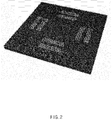
- the graphene transistor of Example 2 was prepared, and detection results when the graphene transistor contacted ammonia, glutamine, putrescine, and cadaverine, in order are shown in FIG. 7 .
Landscapes
- Health & Medical Sciences (AREA)
- Life Sciences & Earth Sciences (AREA)
- Chemical & Material Sciences (AREA)
- Engineering & Computer Science (AREA)
- Immunology (AREA)
- Molecular Biology (AREA)
- Physics & Mathematics (AREA)
- General Physics & Mathematics (AREA)
- Biochemistry (AREA)
- General Health & Medical Sciences (AREA)
- Analytical Chemistry (AREA)
- Pathology (AREA)
- Food Science & Technology (AREA)
- Biomedical Technology (AREA)
- Urology & Nephrology (AREA)
- Hematology (AREA)
- Chemical Kinetics & Catalysis (AREA)
- Electrochemistry (AREA)
- Medicinal Chemistry (AREA)
- Cell Biology (AREA)
- Microelectronics & Electronic Packaging (AREA)
- Biotechnology (AREA)
- Microbiology (AREA)
- Spectroscopy & Molecular Physics (AREA)
- Nanotechnology (AREA)
- Proteomics, Peptides & Aminoacids (AREA)
- Tropical Medicine & Parasitology (AREA)
- Carbon And Carbon Compounds (AREA)
Abstract
Description
- The present invention relates to a graphene channel member comprising a cadaverine olfactory receptor and a sensor comprising same.
- The conventional discrimination platform of meat freshness is a method of monitoring the change of electric resistance by physisorption based on a metal oxide thin film or a nano material, which has a suitable structure for detecting small molecules (hydrogen, ethanol, ammonia, methanol, toluene, or the like), but there are current limits as follows.
- 1. Selectivity - Since the change of electric resistance by physisorption is monitored, at the same concentration, both material A and material B may react, but at different concentrations (in case of excessive amount of material B), though material A has relatively higher sensitivity, the reactivity of material B is monitored to increase.
- 2. Indirect discrimination of meat freshness - If meat decays in practice, a gas generated includes cadaverine and putrescine, but these are supramolecular materials, and there is absolutely no reaction by the conventional physisorption-based platform. Accordingly, the conventional platform had a limitation in that it had to detect ammonia, toluene, or the like as an indirect measure.
- The conventional precedent research for detecting cadaverine has been reported carbon nanotubes combined with cadaverine receptors by the present team of researchers for the first time (Park, Taehyeon, et al., ACS Nano, 2017, 11, 11847-11855). The detection limit by the carbon nanotubes is 10 pM, but an amount of the carbon nanotubes mounted on an electrode is not constant, and insufficient reproducibility of experimental results became a stumbling block in the way of commercialization. Accordingly, in order to overcome such problems, a next-generation nano material capable of replacing the carbon nanotube is required as it is.
- The present invention is made to overcome the above-described limits of the conventional detector for meat freshness, and provides a sensor having reproducibility and high sensitivity by using a graphene channel member including a graphene film and a cadaverine olfactory receptor (Taar13c) immobilized to the graphene film.
- The present invention provides a graphene channel member comprising a graphene film and a cadaverine olfactory receptor immobilized to the graphene film.
- In addition, the present invention provides a graphene transistor comprising: a substrate; the graphene channel member; and a pair of electrodes.
- In addition, the present invention provides a bio sensor comprising the graphene transistor.
- In the case where the graphene film and the cadaverine olfactory receptor (trace amine-associated receptor 13c (Taar13c)) immobilized to the graphene film of the present invention is used as a graphene transistor, the detection limit of cadaverine produced during the decay of meat may be improved, and effects of detecting with high sensitivity and reproducibility may be achieved.
- Particularly, compared to the conventional sensor using a cadaverine receptor in combination with carbon nanotube, effects of achieving excellent detection efficiency, detection limit and reproducibility and detecting gas phase cadaverine as well as liquid phase cadaverine simultaneously may be achieved.
- In addition, the graphene transistor including the graphene channel member of the present invention may be manufactured in a USIM chip type and applied in a miniaturized bio sensor (portable electronic gas sensor, or the like), and effects of very simply and accurately discriminating the freshness of meat may be achieved.
-
-
FIG. 1 shows a graphene transistor according to an embodiment of the present invention. -
FIG. 2 shows minutely patterned graphene film according to an embodiment of the present invention. -
FIG. 3 shows analyzed results of the expressed and purified cadaverine olfactory receptor according to Preparation Example 1 of the present invention by gel staining and western blot. -
FIG. 4 shows measured results of the detection limit of cadaverine of the graphene transistor of Example 2 according to Experimental Example 1 of the present invention. -
FIG. 5 shows photographic images observing the decay degrees of beef with the naked eye according to Experimental Example 2 of the present invention. -
FIG. 6 shows detection results of cadaverine produced from beef using the graphene transistor of Example 2 according to Experimental Example 2 of the present invention. -
FIG. 7 shows evaluation results of cadaverine selectivity of the graphene transistor of Example 2 according to Experimental Example 3 of the present invention. -
FIG. 8 shows results shown in NO2, VBN and VOC detectors which may be commercialized in a bio sensor according to an embodiment of the present invention. -
FIG. 9 is a diagram showing a bio sensor including a graphene transistor according to an embodiment of the present invention. -
FIG. 10 shows 1H-NMR spectrum of Carbene Compound 1 according to Preparation Example 2. -
FIG. 11 shows 1H-NMR spectrum of Carbene Compound 2 according to Preparation Example 3. -
FIG. 12 shows 1H-NMR spectrum of Carbene Compound 3 according to Preparation Example 4. -
FIG. 13 shows 1H-NMR spectrum of Carbene Compound 4 according to Preparation Example 5. -
FIG. 14 shows 1H-NMR spectrum of Carbene Compound 5 according to Preparation Example 6. -
FIG. 15 shows measured results of cadaverine detection limit using the graphene transistor of Comparative Example 1 according to Comparative Experimental Example 1. - Hereinafter, the present invention will be described in detail.
- The present invention provides a graphene channel member including a graphene film and a cadaverine olfactory receptor immobilized to the graphene film.
- The cadaverine olfactory receptor may react with liquid phase cadaverine and/or gas phase cadaverine.
- The cadaverine olfactory receptor may include a trace amine-associated receptor 13c (Taar13c). The Taar13c is one of a receptor related to a trace amount of amine of zebrafish and reacts very sensitively to cadaverine.
- The cadaverine olfactory receptor may have an immobilized type to the surface of the graphene film by a physical bond, or may have an immobilized type by a chemical bond.
- Particularly, the immobilization of the cadaverine olfactory receptor to the surface of the graphene film by a physical bond may be immobilization through physisorption. In this case, the cadaverine olfactory receptor may be immobilized to the surface of the graphene film through physisorption without a separate linker. For example, after treating to the surface of the graphene film, the cadaverine olfactory receptor may be immobilized by a physisorption method of reacting at temperature conditions of about 1 to 10°C for 12 to 48 hours.
- Alternatively, the immobilization of the cadaverine olfactory receptor to the surface of the graphene film by a chemical bond may be bonding (immobilization) by including a carbene compound represented by Formula 1 or Formula 2 below as a linker. That is, the carbene compound may play the role of a medium for chemically immobilizing the cadaverine olfactory to the graphene film. In case of using such a carbene compound as a linker, and the cadaverine olfactory receptor is immobilized to the graphene film, there are advantages in achieving excellent stability to the change of external environment.


- In
Formulae - R1, R2, R5 and R6 are the same or different, and are each independently hydrogen, an alkyl group of 1 to 20 carbon atoms, a cycloalkyl group of 3 to 20 carbon atoms, an aryl group of 6 to 30 carbon atoms, or a heteroaryl group of 2 to 30 carbon atoms,
- R3, R4, R7, R8, R9 and R10 are the same or different, and are each independently hydrogen, an alkyl group of 1 to 20 carbon atoms, a cycloalkyl group of 3 to 20 carbon atoms, an aryl group of 6 to 30 carbon atoms, a heteroaryl group of 2 to 30 carbon atoms, or a structure represented by
Formula 3 below, or two or more adjacent substituents among R7 to R10 are combined to form a hydrocarbon ring, - at least one of R3 and R4 is a structure represented by Formula 3 below, and
- in the case where at least one of R7 to R10 has a structure represented by Formula 3 below, or two or more adjacent substituents among R7 to R10 are combined to form a hydrocarbon ring, at least one hydrogen which is bonded to carbon forming the hydrocarbon ring is substituted with a structure represented by Formula 3 below,

- in Formula 3,
- n is a repeating number of the unit in a parenthesis and an integer of 1 to 30, and
- A is an alkyl group of 1 to 20 carbon atoms, including a nitrogen (N) atom, or a heteroaryl group of 2 to 30 carbon atoms, including a nitrogen (N) atom.
- R1, R2, R5 and R6 may be the same or different, and may be each independently hydrogen, an alkyl group of 1 to 20 carbon atoms or an aryl group of 6 to 30 carbon atoms.
- R1, R2, R5 and R6 may be the same or different, and may be each independently hydrogen, an alkyl group of 1 to 10 carbon atoms or an aryl group of 6 to 10 carbon atoms.
- R1, R2, R5 and R6 may be the same or different, and may be each independently hydrogen, or an alkyl group of 1 to 10 carbon atoms.
- R1, R2, R5 and R6 may be the same or different, and may be each independently hydrogen, isopropyl or benzyl.
- At least one of R1 and R2 and at least one of R5 and R6 may be the same or different, and may be each independently an alkyl group of 1 to 20 carbon atoms or an aryl group of 6 to 30 carbon atoms.
- At least one of R1 and R2 and at least one of R5 and R6 may be the same or different, and may be each independently isopropyl or benzyl.
- R3, R4, R7, R8, R9 and R10 may be the same or different, and may be each independently hydrogen, an alkyl group of 1 to 20 carbon atoms, a cycloalkyl group of 3 to 20 carbon atoms, an aryl group of 6 to 30 carbon atoms, a heteroaryl group of 2 to 30 carbon atoms or a structure represented by
Formula 3, or two or more adjacent substituents among R7 to R10 may be combined to form a hydrocarbon ring. - R3, R4, R7, R8, R9 and R10 may be the same or different, and may be each independently hydrogen, or a structure represented by
Formula 3, or two or more adjacent substituents among R7 to R10 may be combined to form a hydrocarbon ring. - In the case where two or more adjacent substituents among R7 to R10 are combined to form a hydrocarbon ring, at least one hydrogen which is bonded to carbon forming the hydrocarbon ring may be substituted with a structure represented by
Formula 3. - At least one of R3 and R4 may have the structure represented by
Formula 3. In addition, at least one of R7 to R10 may have the structure represented byFormula 3. - The n is a repeating number in the parenthesis and may be an integer of 1 to 30, preferably, 1 to 10. More preferably, n may be 1 to 3.
- The A may be an alkyl group of 1 to 20 carbon atoms, including a nitrogen (N) atom, or a heteroaryl group of 2 to 30 carbon atoms, including a nitrogen (N) atom. Particularly, the A may be azide, phthalimide, or amine.
- In the present invention, an "adjacent" group may mean a substituent substituted at an atom which is directly connected with an atom at which a corresponding substituent is substituted, a substituent sterically at the nearest position to a corresponding substituent, or another substituent substituted at an atom at which a corresponding substituent is substituted. For example, two substituents substituted at ortho positions in a benzene ring, and two substituents substituted at the same carbon in an aliphatic ring may be interpreted as "adjacent" groups to each other.
- The alkyl group may be a linear chain or a branched chain, and may have 1 to 20 carbon atoms, preferably, 1 to 10 carbon atoms. More preferably, the carbon number may be 1 to 6. Particular examples of the alkyl group may include a methyl group, an ethyl group, a propyl group, an n-propyl group, an isopropyl group, a butyl group, an n-butyl group, an isobutyl group, a tert-butyl group, a sec-butyl group, an 1-methylbutyl group, an 1-ethylbutyl group, a pentyl group, an n-pentyl group, an isopentyl group, a neopentyl group, a tert-pentyl group, a hexyl group, an n-hexyl group, an 1-methylpentyl group, a 2-methylpentyl group, a 4-methyl-2-pentyl group, a 3,3-dimethyl butyl group, a 2-ethylbutyl group, a heptyl group, an n-heptyl group, an 1-methylhexyl group, a cyclopentylmethyl group, a cyclohexylmethyl group, an octyl group, an n-octyl group, a tert-octyl group, an 1-methylheptyl group, a 2-ethylhexyl group, a 2-propylpentyl group, an n-nonyl group, a 2,2-dimethylheptyl group, an 1-ethylpropyl group, an 1,1-dimethylpropyl group, an isohexyl group, a 4-methylhexyl group, a 5-methylhexyl group, or a benzyl group, without limitation.
- The cycloalkyl group may have 3 to 20 carbon atoms, preferably, 3 to 10 carbon atoms. Particular examples of the cycloalkyl group may include a cyclopropyl group, a cyclobutyl group, a cyclopentyl group, a 3-methylcyclopentyl group, a 2,3-dimethylcyclopentyl group, a cyclohexyl group, a 3-methylcyclohexyl group, a 4-methylcyclohexyl group, a 2,3-dimethylcyclohexyl group, a 3,4,5-trimethylcyclohexyl group, a 4-tert-butylcyclohexyl group, a cycloheptyl group or a cyclooctyl group, without limitation.
- The aryl group may have 6 to 30 carbon atoms, preferably, 6 to 10 carbon atoms. The aryl group may be a monocyclic aryl group or a polycyclic aryl group. Particular examples of the monocyclic aryl group may include a phenyl group, a biphenyl group or a terphenyl group, and particular examples of the polycyclic aryl group may include a naphthyl group, an anthracenyl group, a phenanthryl group, a pyrenyl group, a perylenyl group, a chrysenyl group, a fluorenyl group, or a triphenylene group, without limitation.
- The heteroaryl group may be an aromatic ring group including one or more selected from N, O, P, S, Si and Se as a heteroatom and having 2 to 30 carbon atoms, preferably, 2 to 20 carbon atoms. Particular examples of the heteroaryl group may include a thiophene group, a furan group, a pyrrole group, an imidazole group, a thiazole group, an oxazole group, an oxadiazole group, a triazole group, a pyridyl group, a pyrimidyl group, a triazine group, a triazole group, an acridyl group, a quinolinyl group, a quinazoline group, a quinoxalinyl group, a phthalazinyl group, an isoquinoline group, an indole group, a carbazole group, a benzoxazole group, a benzimidazole group, a benzothiazole group, a benzocarbazole group, a benzothiophene group, a dibenzothiophene group, or a benzofuranyl group, without limitation.
- In addition, the alkyl group, cycloalkyl group, aryl group, heteroaryl group or hydrocarbon ring may be further substituted or unsubstituted with an alkyl group, cycloalkyl group, aryl group or heteroaryl group.
- After treating the carbene compound to the graphene film, a temperature of 100°C or higher may be applied so that unshared electron pair of the carbene compound may make a chemical bond (covalent bond) with the graphene film.
- The cadaverine olfactory receptor may be chemically bonded to the carbene compound, for example, a functional group at the terminal group of the carbene compound and the functional group of the cadaverine olfactory receptor may make chemical bond by a coupling agent (for example, 4-(4,6-dimethoxy-1,3,5-triazin-2-yl)-4-methylmorpholinium tetrafluoroborate (DMTMM), N-(3-dimethylaminopropyl)-N'-ethylcarbodiimide hydrochloride and N-hydroxysuccinimide (EDC-NHS), glutaraldehyde, or the like).
- Particularly, a sensor using after combining the conventional cadaverine receptor and carbon nanotube, had a detection limit of 10 pM, and the amount of carbon nanotubes mounted on an electrode was not constant, and accordingly, there were problems in reproducibility of the experimental results of a graphene transistor. However, in the graphene channel member of the present invention, a cadaverine olfactory receptor is physically or chemically bonded to a graphene film having high charge mobility, and improved detection efficiency by about 1,000 times or more, particularly, 10,000 times or more, more particularly, 100,000 times or more than a carbon nanotube-based sensor, may be shown, and there are advantages in having a detection limit of 0.1 fM which is further sensitive sensor performance than a case of using the conventional carbon nanotube, and detecting gas phase cadaverine as well as liquid phase cadaverine simultaneously.
- The graphene film may have a single layer or a bi-layer. If a graphene film with a bi-layer is used, the sensitivity of a graphene transistor may be degraded due to the reduction of surface resistance, and in this regard, a graphene film with a single layer is preferably included.
- The graphene film may be patterned, particularly, minutely patterned. On the surface of the patterned graphene film, the cadaverine olfactory receptor may be bonded (immobilized). For example, the graphene film may be patterned into diverse shapes such as a circle, triangle, square, pentagon, and hexagon (honeycomb). In case of patterning the graphene film as described above, patterns of the graphene film with various shapes may be provided, a bio sensor may be miniaturized and easy to carry, and requirement on the design with various shapes of a graphene transistor may be met.
- On the surface of the patterned graphene film, the cadaverine olfactory receptor may be bonded. In this case, the cadaverine olfactory receptor may be immobilized to the surface of the graphene film by a physical bond through physisorption, or may be immobilized to the graphene film by a chemical bond through the carbene compound represented by
Formula 1 orFormula 2 as a linker. - As described above, the graphene channel member includes the graphene film, and in case of using graphene as such a channel member, high current flows in an off state when a voltage is not applied to a gate, the on/off ratio of an operation current is very low, and there are advantages in manufacturing a transistor having high performance.
- In this case, the thickness of the graphene film may be 0.1 to 1 nm, and this may mean the thickness of a graphene film having a single layer. If the thickness of the graphene film satisfies the above-described range, the properties of high conductivity and high charge mobility may be shown, and a graphene transistor with high sensitivity may be manufactured.
- In addition, the present invention provides a graphene transistor including the graphene channel member.
- The graphene transistor of the present invention includes: a substrate; the above-described graphene channel member; and a pair of electrodes.
- The substrate plays the role of a support for supporting the constituents of the graphene transistor of the present invention and may use an insulating inorganic substrate including a Si substrate, a glass substrate, a GaN substrate, a silica (SiO2) substrate, or the like, a metal substrate including Ni, Cu, W, or the like, or a plastic substrate. In case of using the insulating substrate, the silica (SiO2) substrate, or a silicon wafer is preferable in regard of excellent affinity with the graphene channel member.
- In addition, the substrate may be selected from diverse materials on which the deposition of graphene is possible, for example, may be composed of a material including silicon-germanium, silicon carbide (SiC), or the like, and may include an epitaxial layer, a silicon-on-insulator layer, a semiconductor-on-insulator layer, or the like.
- The graphene channel member may be formed on the substrate.
- Particularly, a graphene film may be formed by growing graphene on the substrate by a chemical vapor deposition method using a hydrocarbon gas as a carbon source.
- The graphene film may be formed by using, for example, a chemical vapor deposition method, and by using this method, graphene having a single layer to several layers having excellent crystallinity may be obtained into a large area. The chemical vapor deposition method is a method for growing graphene by separating carbon atoms by adsorbing, decomposing or reacting a carbon precursor in a gas or vapor state, having high kinetic energy onto the surface of a substrate, and making the carbon atoms form atomic bonds from each other.
- The chemical vapor deposition method may be at least one selected from the group consisting of plasma enhanced chemical vapor deposition (PECVD), atmospheric pressure chemical vapor deposition (APCVD) and low pressure chemical vapor deposition (LPCVD), and in view of depositing on a large area while minimizing defects, a preferable chemical vapor deposition method is LPCVD.
- By a particular method of the chemical vapor deposition, for example, a metal catalyst such as nickel, copper, aluminum and iron is deposited using a sputtering apparatus and an electron beam evaporation apparatus on a wafer having a silicon oxide layer to form a metal catalyst layer, this is put in a reactor together with a gas including carbon such as CH4 and C2H2 and heated so that carbon is absorbed into the metal catalyst layer, and then, cooled to separate carbon from the metal catalyst layer for crystallization, and finally, the metal catalyst layer is removed to form a graphene film.
- However, the method of forming the graphene film is not limited to the chemical vapor deposition method, and the graphene film may be formed using various methods.
- For example, a graphene film may be formed by a physical stripping method for forming graphene by stripping one layer from a graphite crystal composed of many layers by a mechanical force, a chemical stripping method utilizing oxidation-reduction properties, or an epitaxial synthetic method by heating a material in which carbon is adsorbed or included such as SiC at a high temperature state of 1,500°C.
- The one pair of electrodes may be a source electrode and a drain electrode separately formed on the graphene film to apply a voltage to the graphene channel member.
- The source electrode and drain electrode may be electrically connected through the graphene film, may include a material having conductivity, and may be formed using, for example, a metal, a metal alloy, a conductive metal oxide, a conductive metal nitride, or the like.
- The source electrode and the drain electrode may each independently include at least one selected from the group consisting of Cu, Co, Bi, Be, Ag, Al, Au, Hf, Cr, In, Mn, Mo, Mg, Ni, Nb, Pb, Pd, Pt, Re, Rh, Sb, Ta, Te, Ti, W, V, Zr, Zn, and combinations thereof, without limitation. Considering contact with graphene and easiness of etching, Au, or a Cr/Au alloy are preferable.
- The one pair of electrodes may be formed by a method well-known in the art and may be formed by a deposition method including, for example, photolithography, thermal deposition, E-beam deposition, plasma enhanced chemical vapor deposition (PECVD), low pressure chemical vapor deposition (LPCVD), physical vapor deposition (PVD), sputtering, atomic layer deposition (ALD), or the like.
- In the graphene channel member, a cadaverine olfactory receptor may be directly bonded (immobilized) to the graphene film by physisorption, or a cadaverine olfactory receptor may be bonded (immobilized) via the carbene compound. With respect to the graphene channel member, the cadaverine olfactory receptor, the carbene compound and the graphene film, the same explanation described above may be applied.
- In the case where the cadaverine olfactory receptor is bonded (immobilized) to the graphene film by including the carbene compound as a linker, the carbene compound bonded to the graphene film may form a linker layer as a single layer type, and the cadaverine olfactory receptor immobilized to the carbene compound may also form a receptor layer as a single layer type.
- If the linker layer is formed into a single layer, excellent charge mobility, transparency and/or flexibility inherent in graphene may be obtained, and effects of blocking noise signals due to the approach of external nonspecific charges may be achieved.
- In addition, the linker layer may have a thickness of 0.1 to 2 nm. If the thickness of the linker layer is smaller than 0.1 nm, there are problems of increasing resistance, and if the thickness is greater than 2 nm, there are problems of degrading transparency.
- Another aspect of the present invention provides a bio sensor including the above-described graphene transistor.
- The bio sensor according to the present invention uses semiconductor characteristics by which current flowing through the graphene film between the source and drain electrodes changes by electric field effects.
- Particularly, if a cadaverine olfactory receptor formed on the surface of the graphene film reacts with cadaverine, surrounding electric field changes, and due to this, a current value flowing through the graphene film between the source electrode and the drain electrode changes concurrently, and by a method of measuring such current change, a target material may be detected.
- Such a bio sensor has excellent sensitivity, specificity, promptness and/or portability by using such a graphene transistor, and particularly, due to the high charge carrier mobility and conductivity properties of graphene by using the graphene film as a channel layer, excellent sensitivity and real-time sensing performance are shown. Accordingly, the detection limit of cadaverine generated during the decay of meat may be improved, and effects of high sensitivity and reproducibility may be achieved.
- In addition, in the case where the above-described linker layer is formed on the graphene film in the graphene transistor, and a cadaverine olfactory receptor layer bonded thereto is present in the channel area of the graphene transistor, the sensitivity of the sensor may be even further improved, and doping treatment and attaching of the cadaverine olfactory receptor may be performed simultaneously, thereby simplifying a process.
- Further, the above-described graphene transistor may be formed into a USIM chip type and may be applied in a miniaturized bio sensor (portable electronic gas sensor, or the like), and the freshness of meat may be simply and accurately discriminated in real-time, and this bio sensor may be utilized in various food industries and environment evaluation industries.
- Hereinafter, the present invention will be explained in more detail referring to preferred embodiments.
- However, these embodiments are only for explaining the present invention more particularly, and the scope of the present invention is not limited thereto.
- In order to express ApoA-I and Taar13c proteins from Escherichia coli (E. coli), ApoA-I and Taar13c genes were cloned first.
- Particularly, the ApoA-I gene was designed so as to include 6xHis and stop codon gene, and was amplified by PCR (primer sequence: 5' CAC CAG GAG ATA TAC ATA TGA AAG CTG CGG TGC TGA CC 3', 5' CTA GTG GTG GTG GTG GTG GTG CTG GGT GTT GAG CTT CTT AGT GTA 3') using human genomic DNA.
- The Taar13c gene was amplified through PCR (primer sequence: 5'-CAC CAG GAG ATA TAC ATA TGA TGC CCT TTT GCC ACA AT 3', 5' TGA ACT CAA TTC CAA AAA TAA TTT ACA C-3') using zebrafish cDNA. Amplified PCR products were inserted into pET-DEST42 vector (Invitrogen, USA) using a gateway cloning system (Invitrogen, USA).
- The Taar13c gene was cloned into a pcDNA3 mammalian expression vector using the amplified PCR product (primer; 5' ATG AAT TCA TGG ATT TAT CAT CAC AAG AAT 3', 5' ATC TCG AGT CAA ACC GTA AAT AAA TTG ATA 3').
- BL21(DE3) E. coli cells bearing a pET-DEST42/ApoA-I construct were cultured in 1 L of Luria-Bertani (LB) medium (+50 µg/mL ampicillin) at 37°C, and then grown until the OD600 value of the cells reached 0.5. In addition, isopropyl thiogalactoside (IPTG) was added to a final concentration of 1 nM to induce the overexpression of ApoA-I.
- After 3 hours, the cells were centrifuged (7000 g, 20 min, 4°C), resuspended in a lysis buffer (20 mM Tris-HCl, 0.5 M NaCl, 20 mM imidazole, pH 8.0), and then disrupted by sonication (5 s on/off, 5 min).
- The disrupted cell lysate was centrifuged at 12,000 g for 30 minutes at 4°C, and ApoA-I in a supernatant was collected and loaded on HisTrap HP column (GE Healthcare, Sweden) through FPLC (GE Healthcare).
- Then, the column was washed with a washing buffer (20 mM Tris-HCl, 50 mM imidazole, 0.5 M NaCl, pH 8.0), and ApoA-I was separated using a separation buffer (20 mM Tris-HCl, 400 mM imidazole, 0.5 M NaCl, pH 8.0) and dialyzed against a HEPES buffer I (20 mM HEPES-NaOH, 100 mM NaCl, 20 mM cholate, 1 mM EDTA, pH 8.0) using a HiTrap HP desalting column (GE Healthcare, Sweden). The protein thus dialyzed was stored at 4°C until used.
- BL21 (DE3) cells transformed with pET-DEST42/Taar13c vector were incubated in an LB medium (+50 µg/mL ampicillin) at 37°C until the OD600 value of the cells reached 0.5. The expression of Taar13c was induced by the addition of 1 mM of IPTG, and the cells were incubated for 4 hours.
- After incubation, the cells were centrifuged (7000 g, 20 min, 4°C), and pellets obtained through the centrifuge were resuspended in PBS including 2 mM EDTA. Then, the cells were disrupted by sonication (5 s on/off, 5 min) to hemolyze the cells, and centrifuged again (12000 g, 4°C, 20 min).
- After repeating the sonication and centrifugation, the pellet of a sample was solubilized in a solubilization buffer (0.1 M Tris-HCl, 20 mM sodium dodecyl sulfate (SDS), 100 mM dithiothreitol (DTT), 1 mM EDTA, pH 8.0). The solubilized protein was dialyzed against a 0.1 M sodium phosphate buffer solution including 10 mM of SDS using a 10 K MWCO dialysis cassette (Thermo Scientific, USA).
- Then, filtering was performed using a 0.2 µm bottle top filter (Thermo Scientific, USA), and applied to a HisTrap HP column equilibrated in 0.1 M sodium phosphate (pH 8.0) including 10 mM of SDS. The column was successively washed with a washing buffer (0.1 M sodium phosphate, 10 mM SDS) until pH reached from 8.0 to 7.0. After that, Taar13c was dissolved in the same buffer of pH 6.0 and separated.
- The protein thus dissolved and separated was dialyzed against a HEPES buffer II (20 mM HEPES-NaOH, 100 mM NaCl, 25 mM cholate, 1 mM EDTA, pH 8.0). Dialyzed and purified Taar13c was analyzed by SDS-PAGE and western blot analysis.
-

- According to the reaction above,
Carbene Compound 1 was prepared. - In
FIG. 10 , 1H-NMR spectrum ofCarbene Compound 1 is shown. -

- According to the reaction above,
Carbene Compound 2 was prepared. - In
FIG. 11 , 1H-NMR spectrum ofCarbene Compound 2 is shown. -

- According to the reaction above,
Carbene Compound 3 was prepared. - In
FIG. 12 , 1H-NMR spectrum ofCarbene Compound 3 is shown. -

- According to the reaction above,
Carbene Compound 4 was prepared. - In
FIG. 13 , 1H-NMR spectrum ofCarbene Compound 4 is shown. -

- According to the reaction above,
Carbene Compound 5 was prepared. - In
FIG. 14 , 1H-NMR spectrum ofCarbene Compound 5 is shown. - A copper foil was positioned in a chamber, heated to 1,000°C, and maintained in 90 mTorr and 8 sccm of H2 for 30 minutes (pre-annealing for 20 minutes and stabilizing for 10 minutes). Then, CH4 was applied in 20 sccm for 40 minutes in a state of a total pressure of 560 mTorr, the temperature was cooled to 200°C in a rate of 35°C/min, and a furnace was cooled to room temperature to form a graphene film (graphene layer) of a single layer on the copper foil.
- Then, on the graphene film formed on the copper foil, a polymethyl methacrylate (PMMA, MicroChem Corp, 950 PMMA A4, 4% in anisole) solution was spin coated in a rate of 6,000 rpm per minute, and the graphene film coated with the PMMA was separated from the copper foil using an etchant. The graphene film separated from the copper foil was immersed in de-ionized distilled water for 10 minutes to remove etchant ions remaining on the graphene film.
- The graphene film thus washed was transferred to a silicon wafer which was a substrate, and a PMMA solution was dropped on the graphene film to remove PMMA coated on the graphene film to form a graphene film on the substrate. In this case, transparency was maintained to 97.8%.
- On the graphene film formed on the substrate, a positive photoresist (AZ5214, Clariant Corp) was spin coated, and the graphene film was patterned through UV exposing, baking and developing processes.
- At both terminals of the graphene film patterned and aligned as above, a pattern electrode (width/length = W/L = 1, L = 100 µm channel length) was formed through an RIE (oxygen plasma treatment) method, and then, through image reversal, thermal deposition and lift-off processes, a graphene transistor in which an electrode (W/L = 5, L = 100 µm channel length) was formed on a portion of the graphene film, was formed.
- On the graphene film, Taar13c of Preparation Example 1 was added and reacted at 4°C for 12 hours or more to immobilize Taar13c to the graphene film to manufacture a graphene transistor.
- A copper foil was positioned in a chamber, heated to 1,000°C, and maintained in 90 mTorr and 8 sccm of H2 for 30 minutes (pre-annealing for 20 minutes and stabilizing for 10 minutes). Then, CH4 was applied in 20 sccm for 40 minutes in a state of a total pressure of 560 mTorr, the temperature was cooled to 200°C in a rate of 35°C/min, and a furnace was cooled to room temperature to form a graphene film (graphene layer) of a single layer on the copper foil.
- Then, on the graphene film formed on the copper foil, a polymethyl methacrylate (PMMA, MicroChem Corp, 950 PMMA A4, 4% in anisole) solution was spin coated in a rate of 6,000 rpm per minute, and the graphene film coated with the PMMA was separated from the copper foil using an etchant. The graphene film separated from the copper foil was immersed in de-ionized distilled water for 10 minutes to remove etchant ions remaining on the graphene film.
- The graphene film thus washed was transferred to a silicon wafer which was a substrate, and a PMMA solution was dropped on the graphene film to remove PMMA coated on the graphene film to form a graphene film on the substrate. In this case, transparency was maintained to 97.8%.
- On the graphene film formed on the substrate, a positive photoresist (AZ5214, Clariant Corp) was spin coated, and the graphene film was patterned through UV exposing, baking and developing processes.
- At both terminals of the graphene film patterned and aligned as above, a pattern electrode (width/length = W/L = 1, L = 100 µm channel length) was formed through an RIE (oxygen plasma treatment) method, and then, through image reversal, thermal deposition and lift-off processes, a graphene transistor in which an electrode (W/L = 5, L = 100 µm channel length) was formed on a portion of the graphene film, was formed.
- Carbene Compound 1 (50 mg) of Preparation Example 1 was dissolved in a THF solvent (10 mL) and was added to the graphene film, mixed with 2 mM of fluorinated tetrabutylammonium, and reacted at room temperature for 30 minutes. Then, the graphene film was washed with THF to form a linker layer.
- The linker layer was treated with 10 µL of a mixture solution of Taar13c of Preparation Example 1 and 3 wt% of DMTMM in a volume ratio of 1:1, reacted at 4°C for 5 hours or more, and washed with a buffer solution to immobilize Taar13c to the linker layer to manufacture a graphene transistor.
- A graphene transistor was manufactured by the same method as in Example 2 except for using carbon nanotube instead of the graphene film in Example 2.
- The graphene transistor of Example 2 was prepared, and a detection experiment was conducted by injecting cadaverine in a concentration of 0.1 fM, 1 fM, 10 fM, 100 fM, 1 pM, 10 pM, or 100 pM. The results are shown in
FIG. 4 . - According to Experimental Example 1 and
FIG. 4 , it could be confirmed that an electric signal was sensed up to a cadaverine concentration of 0.1 fM by the graphene transistor of the present invention, and a very high sensitivity could be confirmed. - 1.8 L of beef was stood at a temperature of 21°C in a humidity of 30%, and observed results from 0 hours to 60 hours are shown in
FIG. 5 , and detection results using the graphene transistor of Example 2 are shown inFIG. 6 . - According to Experimental Example 2 and
FIG. 6 , it could be confirmed that resistance change was rapid after about 15 hours(900 minutes) by cadaverine generated from the beef. - The graphene transistor of Example 2 was prepared, and detection results when the graphene transistor contacted ammonia, glutamine, putrescine, and cadaverine, in order are shown in
FIG. 7 . - According to Experimental Example 3 and
FIG. 7 , it could be confirmed that the graphene transistor of the present invention has cadaverine selectivity. - By using the graphene transistor of Example 2 and a bio sensor including commonly used NO2, VBN, and VOC detectors, manufactured as in
FIG. 9 , real-time detection results on NO2, VBN and VOC generated during the decay of the beef of Experimental Example 2 are shown inFIG. 8 . - The evaluation results on a cadaverine detection limit using the graphene transistor of Comparative Example 1 are shown in
FIG. 15 . - According to Comparative Experimental Example 1 and
FIG. 15 , it could be confirmed that the detection limit was improved by about 100,000 times or more for a case of using the graphene transistor of the present invention when compared to a case of using the graphene transistor of Comparative Example 1.
Claims (12)
- A graphene channel member, comprising a graphene film and a cadaverine olfactory receptor immobilized to the graphene film.
- The graphene channel member according to claim 1, wherein the cadaverine olfactory receptor is immobilized to the graphene film by a physical bond.
- The graphene channel member according to claim 2, wherein the immobilization by the physical bond is immobilization of the cadaverine olfactory receptor to the graphene film through absorption.
- The graphene channel member according to claim 1, wherein the cadaverine olfactory receptor is immobilized to the graphene film by a chemical bond.
- The graphene channel member according to claim 4, wherein the chemical bond is immobilized using a carbene compound represented by the following Formula 1 or Formula 2 as a liker:


 R1, R2, R5 and R6 are the same or different, and are each independently hydrogen, an alkyl group of 1 to 20 carbon atoms, a cycloalkyl group of 3 to 20 carbon atoms, an aryl group of 6 to 30 carbon atoms, or a heteroaryl group of 2 to 30 carbon atoms,R3, R4, R7, R8, R9 and R10 are the same or different, and are each independently hydrogen, an alkyl group of 1 to 20 carbon atoms, a cycloalkyl group of 3 to 20 carbon atoms, an aryl group of 6 to 30 carbon atoms, a heteroaryl group of 2 to 30 carbon atoms, or a structure represented by the following Formula 3, or two or more adjacent substituents among R7 to R10 are combined to form a hydrocarbon ring,at least one of R3 and R4 is a structure represented by the following Formula 3, andin the case where at least one of R7 to R10 has a structure represented by the following Formula 3, or two or more adjacent substituents among R7 to R10 are combined to form a hydrocarbon ring, at least one hydrogen which is bonded to carbon forming the hydrocarbon ring is substituted with a structure represented by the following Formula 3:in Formula 3,
 n is a repeating number of the unit in a parenthesis and an integer of 1 to 30, andA is an alkyl group of 1 to 20 carbon atoms, including a nitrogen (N) atom, or a heteroaryl group of 2 to 30 carbon atoms, including a nitrogen (N) atom.
 - The graphene channel member according to claim 1, wherein the cadaverine olfactory receptor reacts with liquid phase cadaverine or gas phase cadaverine.
- The graphene channel member according to claim 1, wherein the cadaverine olfactory receptor comprises trace amine-associated receptor 13c (Taar13c).
- The graphene channel member according to claim 1, wherein the graphene film has a single layer or a bi-layer.
- The graphene channel member according to claim 1, wherein the graphene film is patterned.
- The graphene channel member according to claim 1, wherein the graphene film has a thickness of 0.1 to 1 nm.
- A graphene transistor, comprising:a substrate;the graphene channel member according to any one of claim 1 to claim 10; anda pair of electrodes.
- A bio sensor comprising the graphene transistor of claim 11.
Applications Claiming Priority (2)
| Application Number | Priority Date | Filing Date | Title |
|---|---|---|---|
| KR20180169873 | 2018-12-26 | ||
| PCT/KR2019/018526 WO2020138982A1 (en) | 2018-12-26 | 2019-12-26 | Graphene channel member comprising cadaverine olfactory receptor and sensor comprising same |
Publications (2)
| Publication Number | Publication Date |
|---|---|
| EP3904882A1 true EP3904882A1 (en) | 2021-11-03 |
| EP3904882A4 EP3904882A4 (en) | 2022-01-12 |
Family
ID=71129840
Family Applications (1)
| Application Number | Title | Priority Date | Filing Date |
|---|---|---|---|
| EP19902534.7A Withdrawn EP3904882A4 (en) | 2018-12-26 | 2019-12-26 | Graphene channel member comprising cadaverine olfactory receptor and sensor comprising same |
Country Status (5)
| Country | Link |
|---|---|
| US (1) | US20220065810A1 (en) |
| EP (1) | EP3904882A4 (en) |
| KR (1) | KR102312299B1 (en) |
| CN (1) | CN113474661A (en) |
| WO (1) | WO2020138982A1 (en) |
Families Citing this family (1)
| Publication number | Priority date | Publication date | Assignee | Title |
|---|---|---|---|---|
| WO2022212932A1 (en) * | 2021-04-02 | 2022-10-06 | Glyciome, Llc | Dysbiotic measurement |
Family Cites Families (12)
| Publication number | Priority date | Publication date | Assignee | Title |
|---|---|---|---|---|
| KR101110805B1 (en) * | 2008-05-07 | 2012-02-24 | 재단법인서울대학교산학협력재단 | Olfactory receptor-functionalized transistors for highly selective bioelectronic nose and biosensor using the same |
| US9612240B2 (en) * | 2010-06-29 | 2017-04-04 | The Trustees Of The University Of Pennsylvania | Biomimetic chemical sensors using nanoelectronic readout of olfactory receptors |
| CN101979707B (en) * | 2010-11-16 | 2012-07-25 | 中国科学院微电子研究所 | Carbon chemical adsorption method for preparing graphene film by using atomic layer deposition |
| CN102590309B (en) * | 2012-02-03 | 2014-04-02 | 游学秋 | Manufacture and application method for graphene transistor and biosensor of graphene transistor |
| US9097658B2 (en) * | 2012-12-06 | 2015-08-04 | International Business Machines Corporation | Carbon based biosensors and processes of manufacturing the same |
| CN105189601A (en) | 2013-03-13 | 2015-12-23 | 麻省理工学院 | Persistent carbenes and related compositions |
| EP2848929A1 (en) * | 2013-09-11 | 2015-03-18 | AIT Austrian Institute of Technology GmbH | Graphene FET-based biosensor |
| JP6619810B2 (en) * | 2014-07-15 | 2019-12-11 | シー2センス, インコーポレイテッド | Preparations for enhanced chemical resistance sensing |
| EP4365591A2 (en) * | 2016-02-24 | 2024-05-08 | Suntory Holdings Limited | Biosensor detecting smell, scent and taste |
| KR101860097B1 (en) * | 2016-03-22 | 2018-06-27 | 서울대학교산학협력단 | Umami taste biosensor using ligand-binding domain of umami taste receptor |
| CN106571173B (en) * | 2016-11-04 | 2018-10-12 | 郑州新世纪材料基因组工程研究院有限公司 | High temperature resistant composite transparent conductive film, preparation method and application |
| CN108821272B (en) * | 2018-07-10 | 2020-06-09 | 盐城工学院 | Method for covalent modification of graphene based on carbene and preparation method of doped anticorrosive coating of graphene |
-
2019
- 2019-12-26 CN CN201980092896.1A patent/CN113474661A/en active Pending
- 2019-12-26 WO PCT/KR2019/018526 patent/WO2020138982A1/en unknown
- 2019-12-26 US US17/418,577 patent/US20220065810A1/en active Pending
- 2019-12-26 KR KR1020190175636A patent/KR102312299B1/en active IP Right Grant
- 2019-12-26 EP EP19902534.7A patent/EP3904882A4/en not_active Withdrawn
Also Published As
| Publication number | Publication date |
|---|---|
| CN113474661A (en) | 2021-10-01 |
| US20220065810A1 (en) | 2022-03-03 |
| KR20200080195A (en) | 2020-07-06 |
| EP3904882A4 (en) | 2022-01-12 |
| KR102312299B1 (en) | 2021-10-14 |
| WO2020138982A1 (en) | 2020-07-02 |
Similar Documents
| Publication | Publication Date | Title |
|---|---|---|
| US9523683B2 (en) | Functionalized polydiacetylene sensors | |
| KR101617941B1 (en) | High-Performance Graphene Aptasensor Based on Field Effect Transistor for Mercury Detection | |
| US7928432B2 (en) | Sensing devices from molecular electronic devices | |
| EP3703134B1 (en) | Biosensor comprising graphene transistor functionalized with n-heterocyclic carbene compound and fabrication method therefor | |
| KR102084088B1 (en) | Sensor for detecting Zika virus and preparation method thereof | |
| EP3904882A1 (en) | Graphene channel member comprising cadaverine olfactory receptor and sensor comprising same | |
| Wang et al. | A bioinspired adhesive‐integrated‐agent strategy for constructing robust gas‐sensing arrays | |
| EP3401969B1 (en) | Organic transistor and gas sensor | |
| KR20220019248A (en) | Compound, Graphene Channel Member and Sensor Comprising the Same | |
| JP3760158B2 (en) | Novel conductive polymer, sensor using the same, and target substance detection method | |
| KR102496941B1 (en) | Cnt film using slick reaction, cnt-based biosensor using the same, and manufacturing method thereof | |
| US20070292601A1 (en) | Thin Film Devices Utilizing Hexabenzocoronenes | |
| KR101183920B1 (en) | Carbon nanotube transister-based gas sensor for detecting organophosphorous compound gas and method for manufacturing the same | |
| KR20220031523A (en) | Graphene Channel Member for Detecting Anti-stress Hormone and Sensor Comprising the Same | |
| KR20220145781A (en) | Graphene Channel Member Comprising Virus Receptors, and Sensor Comprising the Same | |
| KR102334358B1 (en) | Graphene Film Comprising TRPV1 Receptor and Linker, Graphene Transistor Comprising The Same, and Biosensor | |
| KR100601999B1 (en) | A method for detecting a target molecule using a novel electrically conductive polymer | |
| Ajith et al. | Cost Effective Electrochemical sensor for L‐Methionine based on graphitic carbon nitride sheets modified electrode | |
| Gruber et al. | Synthesis of a novel poly (p-phenylene-vinylene) derivative and its application in chemiresistive sensors for electronic noses with an unusual response to organic vapours | |
| JP4048276B2 (en) | Conductive polypyrrole thin film and method for producing the same | |
| JP7283004B2 (en) | Functional group-containing organic molecule detection sensor, detection method, organic molecule detection array, and organic molecule screening method | |
| KR100580620B1 (en) | Novel electrically conductive polymer, sensor using the same and a method for detecting a target molecule using the same | |
| Bange et al. | Carbon Nanotube Array Immunosensor Development | |
| Hayashi et al. | Fine Structures of 8-G-1-(p-YC6H4C≡ CSe) C10H6 (G= H, Cl, and Br) in Crystals and Solutions: Ethynyl Influence and Y-and G-Dependences | |
| JP2006257025A (en) | Pyridylbenzamide |
Legal Events
| Date | Code | Title | Description |
|---|---|---|---|
| STAA | Information on the status of an ep patent application or granted ep patent |
Free format text: STATUS: THE INTERNATIONAL PUBLICATION HAS BEEN MADE |
|
| PUAI | Public reference made under article 153(3) epc to a published international application that has entered the european phase |
Free format text: ORIGINAL CODE: 0009012 |
|
| STAA | Information on the status of an ep patent application or granted ep patent |
Free format text: STATUS: REQUEST FOR EXAMINATION WAS MADE |
|
| 17P | Request for examination filed |
Effective date: 20210723 |
|
| AK | Designated contracting states |
Kind code of ref document: A1 Designated state(s): AL AT BE BG CH CY CZ DE DK EE ES FI FR GB GR HR HU IE IS IT LI LT LU LV MC MK MT NL NO PL PT RO RS SE SI SK SM TR |
|
| A4 | Supplementary search report drawn up and despatched |
Effective date: 20211210 |
|
| RIC1 | Information provided on ipc code assigned before grant |
Ipc: G01N 27/414 20060101ALI20211207BHEP Ipc: G01N 33/543 20060101ALI20211207BHEP Ipc: G01N 33/53 20060101AFI20211207BHEP |
|
| DAV | Request for validation of the european patent (deleted) | ||
| DAX | Request for extension of the european patent (deleted) | ||
| STAA | Information on the status of an ep patent application or granted ep patent |
Free format text: STATUS: EXAMINATION IS IN PROGRESS |
|
| 17Q | First examination report despatched |
Effective date: 20221012 |
|
| REG | Reference to a national code |
Ref country code: DE Ref legal event code: R079 Free format text: PREVIOUS MAIN CLASS: G01N0033680000 Ipc: G01N0027414000 |
|
| GRAP | Despatch of communication of intention to grant a patent |
Free format text: ORIGINAL CODE: EPIDOSNIGR1 |
|
| STAA | Information on the status of an ep patent application or granted ep patent |
Free format text: STATUS: GRANT OF PATENT IS INTENDED |
|
| RIC1 | Information provided on ipc code assigned before grant |
Ipc: B82Y 30/00 20110101ALN20230104BHEP Ipc: G01N 33/543 19850101ALI20230104BHEP Ipc: G01N 33/53 19850101ALI20230104BHEP Ipc: G01N 33/12 19680901ALI20230104BHEP Ipc: G01N 27/414 19900101AFI20230104BHEP |
|
| INTG | Intention to grant announced |
Effective date: 20230131 |
|
| STAA | Information on the status of an ep patent application or granted ep patent |
Free format text: STATUS: THE APPLICATION IS DEEMED TO BE WITHDRAWN |
|
| 18D | Application deemed to be withdrawn |
Effective date: 20230613 |