EP3904775A1 - Ventilation control system and carbon dioxide concentration estimation method - Google Patents
Ventilation control system and carbon dioxide concentration estimation method Download PDFInfo
- Publication number
- EP3904775A1 EP3904775A1 EP18944974.7A EP18944974A EP3904775A1 EP 3904775 A1 EP3904775 A1 EP 3904775A1 EP 18944974 A EP18944974 A EP 18944974A EP 3904775 A1 EP3904775 A1 EP 3904775A1
- Authority
- EP
- European Patent Office
- Prior art keywords
- concentration
- rooms
- ventilation
- control system
- room
- Prior art date
- Legal status (The legal status is an assumption and is not a legal conclusion. Google has not performed a legal analysis and makes no representation as to the accuracy of the status listed.)
- Granted
Links
Images



Classifications
-
- F—MECHANICAL ENGINEERING; LIGHTING; HEATING; WEAPONS; BLASTING
- F24—HEATING; RANGES; VENTILATING
- F24F—AIR-CONDITIONING; AIR-HUMIDIFICATION; VENTILATION; USE OF AIR CURRENTS FOR SCREENING
- F24F7/00—Ventilation
- F24F7/04—Ventilation with ducting systems, e.g. by double walls; with natural circulation
- F24F7/06—Ventilation with ducting systems, e.g. by double walls; with natural circulation with forced air circulation, e.g. by fan positioning of a ventilator in or against a conduit
- F24F7/08—Ventilation with ducting systems, e.g. by double walls; with natural circulation with forced air circulation, e.g. by fan positioning of a ventilator in or against a conduit with separate ducts for supplied and exhausted air with provisions for reversal of the input and output systems
-
- F—MECHANICAL ENGINEERING; LIGHTING; HEATING; WEAPONS; BLASTING
- F24—HEATING; RANGES; VENTILATING
- F24F—AIR-CONDITIONING; AIR-HUMIDIFICATION; VENTILATION; USE OF AIR CURRENTS FOR SCREENING
- F24F11/00—Control or safety arrangements
- F24F11/30—Control or safety arrangements for purposes related to the operation of the system, e.g. for safety or monitoring
-
- F—MECHANICAL ENGINEERING; LIGHTING; HEATING; WEAPONS; BLASTING
- F24—HEATING; RANGES; VENTILATING
- F24F—AIR-CONDITIONING; AIR-HUMIDIFICATION; VENTILATION; USE OF AIR CURRENTS FOR SCREENING
- F24F11/00—Control or safety arrangements
- F24F11/0001—Control or safety arrangements for ventilation
-
- F—MECHANICAL ENGINEERING; LIGHTING; HEATING; WEAPONS; BLASTING
- F24—HEATING; RANGES; VENTILATING
- F24F—AIR-CONDITIONING; AIR-HUMIDIFICATION; VENTILATION; USE OF AIR CURRENTS FOR SCREENING
- F24F11/00—Control or safety arrangements
- F24F11/62—Control or safety arrangements characterised by the type of control or by internal processing, e.g. using fuzzy logic, adaptive control or estimation of values
- F24F11/63—Electronic processing
-
- F—MECHANICAL ENGINEERING; LIGHTING; HEATING; WEAPONS; BLASTING
- F24—HEATING; RANGES; VENTILATING
- F24F—AIR-CONDITIONING; AIR-HUMIDIFICATION; VENTILATION; USE OF AIR CURRENTS FOR SCREENING
- F24F11/00—Control or safety arrangements
- F24F11/62—Control or safety arrangements characterised by the type of control or by internal processing, e.g. using fuzzy logic, adaptive control or estimation of values
- F24F11/63—Electronic processing
- F24F11/64—Electronic processing using pre-stored data
-
- F—MECHANICAL ENGINEERING; LIGHTING; HEATING; WEAPONS; BLASTING
- F24—HEATING; RANGES; VENTILATING
- F24F—AIR-CONDITIONING; AIR-HUMIDIFICATION; VENTILATION; USE OF AIR CURRENTS FOR SCREENING
- F24F11/00—Control or safety arrangements
- F24F11/70—Control systems characterised by their outputs; Constructional details thereof
- F24F11/72—Control systems characterised by their outputs; Constructional details thereof for controlling the supply of treated air, e.g. its pressure
- F24F11/74—Control systems characterised by their outputs; Constructional details thereof for controlling the supply of treated air, e.g. its pressure for controlling air flow rate or air velocity
-
- F—MECHANICAL ENGINEERING; LIGHTING; HEATING; WEAPONS; BLASTING
- F24—HEATING; RANGES; VENTILATING
- F24F—AIR-CONDITIONING; AIR-HUMIDIFICATION; VENTILATION; USE OF AIR CURRENTS FOR SCREENING
- F24F2110/00—Control inputs relating to air properties
- F24F2110/50—Air quality properties
- F24F2110/65—Concentration of specific substances or contaminants
- F24F2110/70—Carbon dioxide
-
- F—MECHANICAL ENGINEERING; LIGHTING; HEATING; WEAPONS; BLASTING
- F24—HEATING; RANGES; VENTILATING
- F24F—AIR-CONDITIONING; AIR-HUMIDIFICATION; VENTILATION; USE OF AIR CURRENTS FOR SCREENING
- F24F2120/00—Control inputs relating to users or occupants
- F24F2120/10—Occupancy
-
- Y—GENERAL TAGGING OF NEW TECHNOLOGICAL DEVELOPMENTS; GENERAL TAGGING OF CROSS-SECTIONAL TECHNOLOGIES SPANNING OVER SEVERAL SECTIONS OF THE IPC; TECHNICAL SUBJECTS COVERED BY FORMER USPC CROSS-REFERENCE ART COLLECTIONS [XRACs] AND DIGESTS
- Y02—TECHNOLOGIES OR APPLICATIONS FOR MITIGATION OR ADAPTATION AGAINST CLIMATE CHANGE
- Y02B—CLIMATE CHANGE MITIGATION TECHNOLOGIES RELATED TO BUILDINGS, e.g. HOUSING, HOUSE APPLIANCES OR RELATED END-USER APPLICATIONS
- Y02B30/00—Energy efficient heating, ventilation or air conditioning [HVAC]
- Y02B30/70—Efficient control or regulation technologies, e.g. for control of refrigerant flow, motor or heating
Definitions
- the present invention relates to a ventilation control system that ventilates a space that needs ventilating, and to a carbon dioxide concentration estimation method.
- a ventilation control system includes a blower to discharge indoor air to the outdoors and a CO 2 sensor to detect the indoor CO 2 concentration.
- the ventilation control system disclosed in Patent Literature 1 includes a ventilation device, a human detecting sensor capable of detecting the presence or absence of a person, a CO 2 sensor capable of detecting the CO 2 concentration, and a control device.
- the ventilation device, the human detecting sensor, and the CO 2 sensor are installed in one space.
- the control device of the ventilation control system disclosed in Patent Literature 1 controls the ventilation device such that the ventilation amount of the ventilation device is switched on the basis of the output signal from the human detecting sensor when the output signal from the CO 2 sensor indicates that a CO 2 concentration is less than a threshold.
- Patent Literature 1 Japanese Patent No. 5999353
- the ventilation device For the ventilation control system disclosed in Patent Literature 1, it is required that the ventilation device, the human detecting sensor, and the CO 2 sensor be installed in each room. In a case in which a single ventilation device is required to ventilate multiple rooms with a CO 2 sensor installed in one of the multiple rooms or at an inlet port of the ventilation device, it is not possible to monitor the CO 2 concentration in each room. As a result, the CO 2 concentration can increase due to insufficient ventilation.
- the present invention has been made in view of the foregoing, and it is an object of the present invention to provide a ventilation control system capable of ventilating multiple rooms, using a single ventilation device while preventing the CO 2 concentration from increasing due to insufficient ventilation.
- the present invention is directed to a ventilation control system comprising: a ventilation device to ventilate a plurality of rooms, the ventilation device including a CO 2 sensor to measure a CO 2 concentration in exhaust air discharged from the plurality of rooms; and a plurality of human detection means each installed in a corresponding one of the plurality of rooms to detect presence of a room occupant.
- the ventilation device includes a control device to estimate a CO 2 concentration of each of the plurality of rooms on a basis of the CO 2 concentration measured by the CO 2 sensor and detection results provided by the plurality of human detection means.
- the ventilation control system according to the present invention is advantageous in being capable of ventilating multiple rooms using the single ventilation device while preventing the CO 2 concentration from increasing due to the insufficient ventilation.
- FIG. 1 is a diagram illustrating wiring of a ventilation control system according to a first embodiment of the present invention.
- a ventilation control system 50 according to the first embodiment includes a ventilation device 1, an air conditioner 5, a remote controller 6, and lighting equipment 7.
- the air conditioner 5 for conditioning the indoor temperature is installed in a room 4a.
- the remote controller 6 for controlling the air conditioner 5 is provided in a room 4b.
- the lighting equipment 7 is installed in a room 4c.
- the ventilation device 1 is connected to the air conditioner 5 via a connection line 8.
- the ventilation device 1 is also connected to the remote controller 6 via a connection line 9.
- the ventilation device 1 is further connected to the lighting equipment 7 via a connection line 10.
- FIG. 2 is a diagram illustrating piping of the ventilation control system according to the first embodiment.
- the ventilation device 1 is connected to the rooms 4a, 4b, and 4c by means of an air supply duct 2 for taking in fresh outdoor air and supplying the outdoor air to the multiple rooms 4a, 4b, and 4c.
- the ventilation device 1 is connected to the rooms 4a, 4b, and 4c also by means of an air discharge duct 3 for taking in air in the rooms 4a, 4b, and 4c and discharging the air to the outdoors.
- the air conditioner 5 includes a human detecting sensor installed therein.
- the human detecting sensor is human detection means for detecting the presence or absence of a person in the room.
- the air conditioner 5 is capable of stopping the operation of the air conditioner 5 or controlling the set temperature of the air conditioner 5.
- the air conditioner 5 can be controlled, during cooling operation, such that the cooling operation stops or the set temperature of cooling is raised by a certain temperature to thereby save energy when the presence-absence information has changed to "unoccupied" for a certain time period.
- the presence-absence information detected by the human detecting sensor included in the air conditioner 5 is transmitted from the air conditioner 5 to the ventilation device 1 via the connection line 8.
- the presence-absence information is converted into a communication signal or into a voltage signal, and is transmitted on the connection line 8.
- the ventilation device 1 and the air conditioner 5 may be connected to each other via wireless communication.
- the remote controller 6 includes a human detecting sensor installed therein, which sensor is human detection means for detecting the presence or absence of a person in the room. With the presence-absence information detected by the human detecting sensor, the remote controller 6 is capable of stopping an operation of a device such as the air conditioner 5 or controlling the set temperature of the device. For example, the remote controller 6 can control the air conditioner 5 such that, during heating operation, the air conditioner 5 stops or the set temperature of heating of the air conditioner 5 is lowered by a certain temperature to thereby save energy when the presence-absence information has changed to "unoccupied" for a certain time period.
- the presence-absence information detected by the human detecting sensor included in the remote controller 6 is transmitted from the remote controller 6 to the ventilation device 1 via the connection line 9.
- the presence-absence information is converted into a communication signal or into a voltage signal, and is transmitted on the connection line 9.
- the ventilation device 1 and the remote controller 6 may be connected to each other via wireless communication.
- the lighting equipment 7 includes a human detecting sensor installed therein, which sensor is human detection means for detecting the presence or absence of a person in the room. With the presence-absence information detected by the human detecting sensor, the lighting equipment 7 is capable of turning on/off the lighting equipment 7 or controlling the illuminance of the lighting equipment 7. For example, when the light is in an Off state during which the presence-absence information changes to "occupied", the light can be turned on. In addition, when the light is in an On state during which the presence-absence information has changed to "unoccupied” for a certain time period, the light can be turned off.
- the presence-absence information detected by the human detecting sensor installed in the lighting equipment 7 is transmitted from the lighting equipment 7 to the ventilation device 1 via the connection line 10.
- the presence-absence information is converted into a communication signal or into a voltage signal, and is transmitted on the connection line 10.
- the ventilation device 1 and the lighting equipment 7 may be connected to each other via wireless communication.
- a device including human detection means capable of detecting the presence of a person may also be, for example, a security system that manages people entering and leaving a building or the rooms 4a, 4b, and 4c, using a card key.
- the security system and the ventilation device 1 are connected to each other via wired or wireless communication, thereby allowing entering-leaving information held by the security system to be transmitted from the security system to the ventilation device 1.
- a separate human detecting sensor can be installed in each of the rooms 4a, 4b, and 4c to enable the ventilation device 1 to collect the presence-absence information directly from the human detecting sensors.
- any device capable of detecting the presence of a person can be used as a human detecting sensor.
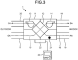
- FIG. 3 is a diagram illustrating a configuration of the ventilation device of the ventilation control system according to the first embodiment.
- the ventilation device 1 includes a heat exchanger 12, an air discharge blower 13, and an air supply blower 14 all of which are disposed in a body housing 11.
- the air supply blower 14 is disposed in a supply airway 15, and supplies air from an outdoor-side inlet OA through the heat exchanger 12 to an indoor-side outlet SA provided in each of the multiple rooms.
- the air discharge blower 13 is disposed in a discharge airway 16, and discharges air from an indoor-side inlet RA provided in each of the multiple rooms through the heat exchanger 12 to an outdoor-side outlet EA.
- the ventilation device 1 uses the heat exchanger 12 to effect heat exchange between supplied air and discharged air.
- the outdoor-side inlet OA is connected to the ventilation device 1 via an outdoor-side duct 17.
- the ventilation device 1 is connected to the multiple indoor-side outlets SA via a supply-side duct 18.
- the multiple indoor-side inlets RA are connected to the ventilation device 1 via an indoor-side duct 19.
- the ventilation device 1 is connected to the outdoor-side outlet EA via a discharge-side duct 20.
- the supply-side duct 18 branches at some point into connection to the multiple indoor-side outlets SA.
- the indoor-side duct 19 branches at some point into connection to the multiple indoor-side inlets RA.
- the outdoor-side duct 17 and the supply-side duct 18 are each the air supply duct 2.
- the indoor-side duct 19 and the discharge-side duct 20 are each the air discharge duct 3.
- a CO 2 sensor 21 for measuring CO 2 concentration in the discharge airway 16 is disposed in the discharge airway 16 inside the ventilation device 1.
- the CO 2 concentration in the discharge airway 16 is the CO 2 concentration of mixed air that is a mixture of the exhaust air from the rooms 4a, 4b, and 4c. That is, the CO 2 concentration in the discharge airway 16 represents the total volume of CO 2 gas contained in the total volume of the exhaust air discharged from the rooms 4a, 4b, and 4c.
- the air discharge blower 13 and the air supply blower 14 are independently driven and controlled by a control device 22.
- the control device 22 is connected to the CO 2 sensor 21, and can thus receive information on the CO 2 concentration measured by the CO 2 sensor 21.
- An operation device 23 connected to the control device 22 operates the ventilation device 1, and checks a state of the ventilation device 1.
- FIG. 4 is a functional block diagram of the control device of the ventilation control system according to the first embodiment.
- the control device 22 includes a power circuit 32 connected to a commercial power supply 31.
- the power circuit 32 supplies electrical power to a control unit 33 and each circuit.
- the ventilation device 1 is connected with the operation device 23.
- the operation device 23 is capable of displaying information such as an operating state of the ventilation device, the operational air flow rate of the air discharge blower 13, and the operational air flow rate of the air supply blower 14.
- the operation device 23 is also capable of stopping the operation of the ventilation device, and setting operating notches of the air discharge blower 13 and of the air supply blower 14.
- the operation device 23 is connected to the control unit 33 via an operation device communication circuit 37.
- the CO 2 sensor 21 disposed in the discharge airway 16 measures the CO 2 concentration, and outputs a CO 2 concentration signal.
- the CO 2 sensor 21 is connected to the control unit 33 via a CO 2 sensor signal reception circuit 36 for receiving the CO 2 concentration signal.
- the control device 22 also includes a functional setting circuit 40 having, for example, a switch for setting the operating notch of the air discharge blower 13 or of the air supply blower 14 on the basis of the presence-absence information or the CO 2 concentration.
- a functional setting circuit 40 having, for example, a switch for setting the operating notch of the air discharge blower 13 or of the air supply blower 14 on the basis of the presence-absence information or the CO 2 concentration.
- the control unit 33 is capable of receiving signals from the CO 2 sensor signal reception circuit 36, the operation device communication circuit 37, a presence-absence information reception circuit 38, and the functional setting circuit 40, outputting a drive command to an air supply blower drive circuit 34 to drive the air supply blower 14, and outputting a drive command to an air discharge blower drive circuit 35 to drive the air discharge blower 13.
- the control unit 33 In accordance with the CO 2 concentration detected by the CO 2 sensor 21 or the CO 2 concentration of each of the rooms 4a, 4b, and 4c, the control unit 33 outputs a drive command to the air supply blower drive circuit 34 to drive the air supply blower 14 and outputs a drive command to the air discharge blower drive circuit 35 to drive the air discharge blower 13.
- the control unit 33 operates the air discharge blower 13 and the air supply blower 14 in a high power mode when the highest CO 2 concentration of a room among the rooms 4a, 4b, 4c is equal to or greater than 800 ppm, the highest CO 2 concentration being highest of CO 2 concentrations of the rooms 4a, 4b, and 4c.
- the control unit 33 operates the air discharge blower 13 and the air supply blower 14 in a low power mode when the highest CO 2 concentration of a room among the rooms 4a, 4b, 4c is equal to or greater than 500 ppm and less than 800 ppm, the highest CO 2 concentration being highest of CO 2 concentrations of the rooms 4a, 4b, and 4c.
- the control unit 33 operates the air discharge blower 13 and the air supply blower 14 in a very low power mode when the highest CO 2 concentration of a room among the rooms 4a, 4b, 4c is less than 500 ppm, the highest CO 2 concentration being highest of CO 2 concentrations of the rooms 4a, 4b, and 4c.
- a process performed by the control unit 33 for estimating the CO 2 concentration of each of the rooms 4a, 4b, and 4c will next be described.
- the example is described below on the assumption that the presence-absence information on the room 4a is "occupied”, the presence-absence information on the room 4b is "unoccupied”, and the presence-absence information on the room 4c is "occupied", and that the CO 2 concentration in the discharge airway 16 is 800 ppm.
- the CO 2 concentrations of the rooms 4a and 4c are estimated from "the amount of CO 2 gas contained in the exhaust air discharged through the ventilation device 1" and "the amount of CO 2 gas contained in the exhaust air discharged from the room 4b".
- CO 2 concentration of the room 4c is also 1000 ppm.
- the control device 22 Since the CO 2 concentrations of the rooms 4a and 4c are 1000 ppm, the control device 22 operates the air supply blower 14 and the air discharge blower 13 in a high power mode.
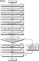
- FIG. 5 is a flowchart illustrating a process of a carbon dioxide concentration estimation method performed by the ventilation control system according to the first embodiment.
- the CO 2 concentration estimation process starts with step S101 at which the control device 22 receives CO 2 concentration information from the CO 2 sensor 21 disposed in the discharge airway 16. Note that the values of the CO 2 concentration received during a certain time period in the past may be averaged to thereby remove or prevent an anomaly caused by noise or the like. That is, the CO 2 concentration measured by the CO 2 sensor 21 may be an average value of multiple measured values.
- the control device 22 performs the subsequent part of the CO 2 concentration estimation process for each room, using the CO 2 concentration information obtained at step S101.
- the subsequent part of the estimation process may be canceled determining that the sensor is anomalous though not illustrated in FIG. 5 .
- anomaly include 0 ppm indicating that no CO 2 has been detected, and a value that is one or more orders of magnitude higher than 400 ppm that is a typical CO 2 concentration in the air.
- the control device 22 receives presence-absence information from the air conditioner 5, the remote controller 6, and the lighting equipment 7 installed in the rooms 4a, 4b, and 4c, respectively.
- the control device 22 performs the subsequent part of the CO 2 concentration estimation process for the rooms 4a, 4b, and 4c, using the presence-absence information obtained at step S102. Note that the indoor CO 2 gas is not discharged immediately after the presence-absence information on one of the rooms 4a, 4b, and 4c changes from "occupied” to "unoccupied", in which case a large error may occur between the estimated value and the actual value.
- the CO 2 concentration estimation process for the rooms 4a, 4b, and 4c may be performed regarding the presence-absence information as remaining "occupied” for a certain time period after the change in the presence-absence information from "occupied" to "unoccupied”. That is, the CO 2 concentration estimation process for the rooms 4a, 4b, and 4c may be performed regarding room occupants as being present for a certain time period after no room occupant has been detected.
- the control device 22 sets the volume of the exhaust air to be discharged by the ventilation device 1 from each of the rooms 4a, 4b, and 4c.
- the volumes of the exhaust air may be deemed as the same as one another.
- the volume of the exhaust air may be individually set for the rooms 4a, 4b, and 4c.
- the volumes of the exhaust air to be discharged from the rooms 4a, 4b, and 4c may be set by the functional setting circuit 40.
- the volumes of the exhaust air to be discharged from the rooms 4a, 4b, and 4c may be set in correspondence with the cooling or the heating capacity of the air conditioner 5. That is, the control device 22 may receive information on the cooling capacity or the heating capacity from the air conditioner 5, and then set the volumes of the exhaust air on the basis of the received information.
- the air conditioner 5 having a cooling capacity of 5.6 kW can typically cool a room having an area of about 32 m 2 .
- Act on Maintenance of Sanitation in Buildings provides for a required ventilation amount of 25 to 30 m 3 /h per person in a case where the number of room occupants per 1 m 2 is 0.2.
- the volumes of the exhaust air to be discharged from the rooms 4a, 4b, and 4c may be set in correspondence to the power consumption of lighting equipment installed in each room. That is, the control device 22 may receive information on the power consumption from the lighting equipment installed in each room, and then set the volumes of the exhaust air on the basis of the received information.
- a room having a floor area of 16 m 2 typically needs a fluorescent lamp of about 100 W.
- the control device 22 performs the subsequent part of the CO 2 concentration estimation process for each room, using the volume of the exhaust air discharged from each room obtained at step S103.
- the control device 22 calculates the amount of CO 2 gas in the exhaust air discharged to the outdoors by the ventilation device 1.
- the amount of CO 2 gas in the exhaust air discharged by the ventilation device 1 is calculated by multiplication of "the volume of the exhaust air that the ventilation device 1 can discharge” by "the CO 2 concentration obtained at step S101".
- the control device 22 calculates the amount of CO 2 gas in the exhaust air discharged from the room determined to be unoccupied from the presence-absence information on each of the rooms 4a, 4b, and 4c obtained at step S102.
- the amount of CO 2 gas in the exhaust air discharged from the room determined to be unoccupied is calculated by multiplication of "the CO 2 concentration in the air" by "the volume of the exhaust air discharged from the room, set at step S103".
- the CO 2 concentration in the air may be set to any value, using the functional setting circuit 40 in view of a possible situation where a building is located in an environment, for example, along a major road having a CO 2 concentration higher than a normal value.
- the CO 2 concentration at the time when all the rooms have been unoccupied for a time period during which the air in the rooms can be replaced with fresh air may be regarded as the CO 2 concentration in the ambient air.
- the control device 22 calculates the sum of the volumes of the exhaust air discharged from the rooms having the presence-absence information representing "occupied", among all the rooms.
- the sum of the capacities of the exhaust air discharged from the occupied rooms is calculated using the volume of the exhaust air discharged from each of the rooms obtained at step S103.
- step S107 to step S111 is performed on a room-by-room basis.
- N is 1.
- the repeat process proceeds from step S107 to step S112, after which N is incremented by one.
- the processes from step S107 to step S112 are subsequently performed again.
- the repeat process terminates, thereby terminating the process of estimating the CO 2 concentration. That is, the repeat process is performed using the variable N from an initial value of 1 to a final value of 3, and an increment of 1.
- control device 22 determines, at step S108, whether the presence-absence information on the room having the room number N is "occupied". If the presence-absence information on the room having the room number N is "occupied", that is, Yes at step S108, the process proceeds to step S109.
- the control device 22 calculates the amount of CO 2 gas in the exhaust air discharged from the room having the room number N that is occupied.
- the amount of CO 2 gas in the exhaust air discharged from the room having the room number N is calculated by: subtracting the total value of "the amount(s) of CO 2 gas in the exhaust air discharged from the unoccupied room(s) calculated at step S105" from "the amount of CO 2 gas in the exhaust air discharged to the outdoors by the ventilation device 1 calculated at step S104"; dividing the resulting difference by "the sum of the volumes of the exhaust air discharged from the occupied rooms calculated at step S106"; and multiplying the resulting quotient by "the volume of the exhaust air to be discharged from the room that has been set at step S103".
- the control device 22 calculates the CO 2 concentration in the exhaust air discharged from the room having the room number N.
- the CO 2 concentration in the exhaust air discharged from the room having the room number N is calculated by dividing "the amount of CO 2 gas in the exhaust air discharged from the room calculated at step S109" by "the volume of the exhaust air to be discharged from the room that has been set at step S103".
- the control device 22 sets, at step S111, the CO 2 concentration of the room having the room number N to the CO 2 concentration in an unoccupied state.
- the CO 2 concentration in an unoccupied state is set to the same value as that of the CO 2 concentration in the ambient air. Note that when no occupant has been detected for a certain time period for all the rooms 4a, 4b, and 4c, the CO 2 concentration of each of the rooms 4a, 4b, and 4c may be estimated to be the CO 2 concentration measured by the CO 2 sensor 21.
- N is incremented by one, after which the process restarts from step S107.
- the repeat process terminates.
- the CO 2 concentration of each room cannot be detected only by the CO 2 sensor 21 disposed in the discharge airway 16 of the ventilation device 1.
- performing the foregoing operation in combination with the human detecting sensor installed in each room enables estimating the CO 2 concentration of each room. This can prevent the CO 2 concentration in a particular room from increasing due to insufficient ventilation.
- the human detecting sensors may be installed in the rooms separately from the air conditioner 5, the remote controller 6, and the lighting equipment 7.
- the functionality of the control unit 33 of the ventilation control system 50 according to the first embodiment described above is implemented in a processing circuitry.
- the processing circuitry may be a dedicated hardware element or a processing unit that executes a program stored in a memory device.
- FIG. 6 is a diagram illustrating a configuration in which the functionality of the control unit of the ventilation control system according to the first embodiment is implemented in hardware.
- a processing circuitry 29 incorporates therein a logic circuit 29a that implements the functionality of the control unit 33.
- control unit 33 In a case in which the processing circuitry 29 is a processing unit, the functionality of the control unit 33 is implemented in software, firmware, or a combination of software and firmware.
- FIG. 7 is a diagram illustrating a configuration in which the functionality of the control unit of the ventilation control system according to the first embodiment is implemented in software.
- the processing circuitry 29 includes a processor 291 that executes a program 29b, a random access memory 292 used for a work area by the processor 291, and a memory device 293 for storing the program 29b.
- the functionality of the control unit 33 is implemented by the processor 291 by expanding the program 29b stored in the memory device 293 on the random access memory 292 and executing the program 29b.
- the software or firmware is described in a program language, and is stored in the memory device 293.
- One example of the processor 291 is, but not limited to, a central processing unit.
- the memory device 293 may be a semiconductor memory such as a random access memory (RAM), a read-only memory (ROM), a flash memory, an erasable programmable read-only memory (EPROM), or an electrically erasable programmable read-only memory (EEPROM) (registered trademark).
- the semiconductor memory may be a non-volatile memory or a volatile memory.
- the memory device 293 may alternatively be a magnetic disk, a flexible disk, an optical disk, a compact disc, a MiniDisc, or a digital versatile disc (DVD), rather than a semiconductor memory.
- the processor 291 may output and store data such as a computing result to and in the memory device 293, or may store such data in an auxiliary memory device (not illustrated) via the random access memory 292. Integration of the processor 291, the random access memory 292, and the memory device 293 on a single chip enables the functionality of the control unit 33 to be implemented in a microcomputer.
- the processing circuitry 29 implements the functionality of the control unit 33 by reading and executing the program 29b stored in the memory device 293. It can also be said that the program 29b causes a computer to perform a procedure and a method for implementing the functionality of the control unit 33.
- processing circuitry 29 may implement the functionality of the control unit 33 partially in a dedicated hardware element and partially in software or firmware.
- processing circuitry 29 can implement the foregoing functionality in hardware, software, firmware, or a combination thereof.
- the foregoing embodiment has been described as to the ventilation control system 50, which estimates the CO 2 concentration of each of the rooms 4a, 4b, and 4c from the CO 2 concentration in the ventilation device 1, the presence-absence information on each of the rooms 4a, 4b, and 4c, and the capacity information on the exhaust air from each of the rooms 4a, 4b, and 4c.
- the procedure described herein is applicable as a carbon dioxide concentration estimation method in various occasions, and is effective in applications other than ventilation control.
Landscapes
- Engineering & Computer Science (AREA)
- Chemical & Material Sciences (AREA)
- Combustion & Propulsion (AREA)
- Mechanical Engineering (AREA)
- General Engineering & Computer Science (AREA)
- Signal Processing (AREA)
- Physics & Mathematics (AREA)
- Fuzzy Systems (AREA)
- Mathematical Physics (AREA)
- Fluid Mechanics (AREA)
- Air Conditioning Control Device (AREA)
- Ventilation (AREA)
Abstract
Description
- The present invention relates to a ventilation control system that ventilates a space that needs ventilating, and to a carbon dioxide concentration estimation method.
- Standards for indoor carbon dioxide content, that is, standards for carbon dioxide concentration are established by law for architecture including a building. Carbon dioxide is hereinafter referred to as CO2. In order to meet this standard, it is necessary to change the ventilation amount in conformity with CO2 concentration. To this end, a ventilation control system includes a blower to discharge indoor air to the outdoors and a CO2 sensor to detect the indoor CO2 concentration.
- The ventilation control system disclosed in
Patent Literature 1 includes a ventilation device, a human detecting sensor capable of detecting the presence or absence of a person, a CO2 sensor capable of detecting the CO2 concentration, and a control device. For the ventilation control system disclosed inPatent Literature 1, the ventilation device, the human detecting sensor, and the CO2 sensor are installed in one space. The control device of the ventilation control system disclosed inPatent Literature 1 controls the ventilation device such that the ventilation amount of the ventilation device is switched on the basis of the output signal from the human detecting sensor when the output signal from the CO2 sensor indicates that a CO2 concentration is less than a threshold. - Patent Literature 1:
Japanese Patent No. 5999353 - For the ventilation control system disclosed in
Patent Literature 1, it is required that the ventilation device, the human detecting sensor, and the CO2 sensor be installed in each room. In a case in which a single ventilation device is required to ventilate multiple rooms with a CO2 sensor installed in one of the multiple rooms or at an inlet port of the ventilation device, it is not possible to monitor the CO2 concentration in each room. As a result, the CO2 concentration can increase due to insufficient ventilation. - The present invention has been made in view of the foregoing, and it is an object of the present invention to provide a ventilation control system capable of ventilating multiple rooms, using a single ventilation device while preventing the CO2 concentration from increasing due to insufficient ventilation.
- To solve the problem and achieve the object described above, the present invention is directed to a ventilation control system comprising: a ventilation device to ventilate a plurality of rooms, the ventilation device including a CO2 sensor to measure a CO2 concentration in exhaust air discharged from the plurality of rooms; and a plurality of human detection means each installed in a corresponding one of the plurality of rooms to detect presence of a room occupant. The ventilation device includes a control device to estimate a CO2 concentration of each of the plurality of rooms on a basis of the CO2 concentration measured by the CO2 sensor and detection results provided by the plurality of human detection means.
- The ventilation control system according to the present invention is advantageous in being capable of ventilating multiple rooms using the single ventilation device while preventing the CO2 concentration from increasing due to the insufficient ventilation.
-
-
FIG. 1 is a diagram illustrating wiring of a ventilation control system according to a first embodiment of the present invention. -
FIG. 2 is a diagram illustrating piping of the ventilation control system according to the first embodiment. -
FIG. 3 is a diagram illustrating a configuration of the ventilation device of the ventilation control system according to the first embodiment. -
FIG. 4 is a functional block diagram of the control device of the ventilation control system according to the first embodiment. -
FIG. 5 is a flowchart illustrating a process of a carbon dioxide concentration estimation method performed by the ventilation control system according to the first embodiment. -
FIG. 6 is a diagram illustrating a configuration in which the functionality of the control unit of the ventilation control system according to the first embodiment is implemented in hardware. -
FIG. 7 is a diagram illustrating a configuration in which the functionality of the control unit of the ventilation control system according to the first embodiment is implemented in software. - A ventilation control system and a carbon dioxide concentration estimation method according to an embodiment of the present invention will be described in detail below with reference to the drawings. Note that this embodiment is not intended to limit the scope of this invention.
-
FIG. 1 is a diagram illustrating wiring of a ventilation control system according to a first embodiment of the present invention. Aventilation control system 50 according to the first embodiment includes aventilation device 1, anair conditioner 5, aremote controller 6, andlighting equipment 7. Theair conditioner 5 for conditioning the indoor temperature is installed in aroom 4a. Theremote controller 6 for controlling theair conditioner 5 is provided in aroom 4b. In addition, thelighting equipment 7 is installed in aroom 4c. Theventilation device 1 is connected to theair conditioner 5 via aconnection line 8. Theventilation device 1 is also connected to theremote controller 6 via aconnection line 9. Theventilation device 1 is further connected to thelighting equipment 7 via aconnection line 10. -
FIG. 2 is a diagram illustrating piping of the ventilation control system according to the first embodiment. In theventilation control system 50 according to the first embodiment, theventilation device 1 is connected to therooms air supply duct 2 for taking in fresh outdoor air and supplying the outdoor air to themultiple rooms ventilation device 1 is connected to therooms air discharge duct 3 for taking in air in therooms - The
air conditioner 5 includes a human detecting sensor installed therein. The human detecting sensor is human detection means for detecting the presence or absence of a person in the room. On the basis of presence-absence information detected by the human detecting sensor, theair conditioner 5 is capable of stopping the operation of theair conditioner 5 or controlling the set temperature of theair conditioner 5. For example, theair conditioner 5 can be controlled, during cooling operation, such that the cooling operation stops or the set temperature of cooling is raised by a certain temperature to thereby save energy when the presence-absence information has changed to "unoccupied" for a certain time period. - The presence-absence information detected by the human detecting sensor included in the
air conditioner 5 is transmitted from theair conditioner 5 to theventilation device 1 via theconnection line 8. The presence-absence information is converted into a communication signal or into a voltage signal, and is transmitted on theconnection line 8. Note that theventilation device 1 and theair conditioner 5 may be connected to each other via wireless communication. - The
remote controller 6 includes a human detecting sensor installed therein, which sensor is human detection means for detecting the presence or absence of a person in the room. With the presence-absence information detected by the human detecting sensor, theremote controller 6 is capable of stopping an operation of a device such as theair conditioner 5 or controlling the set temperature of the device. For example, theremote controller 6 can control theair conditioner 5 such that, during heating operation, theair conditioner 5 stops or the set temperature of heating of theair conditioner 5 is lowered by a certain temperature to thereby save energy when the presence-absence information has changed to "unoccupied" for a certain time period. - The presence-absence information detected by the human detecting sensor included in the
remote controller 6 is transmitted from theremote controller 6 to theventilation device 1 via theconnection line 9. The presence-absence information is converted into a communication signal or into a voltage signal, and is transmitted on theconnection line 9. Note that theventilation device 1 and theremote controller 6 may be connected to each other via wireless communication. - The
lighting equipment 7 includes a human detecting sensor installed therein, which sensor is human detection means for detecting the presence or absence of a person in the room. With the presence-absence information detected by the human detecting sensor, thelighting equipment 7 is capable of turning on/off thelighting equipment 7 or controlling the illuminance of thelighting equipment 7. For example, when the light is in an Off state during which the presence-absence information changes to "occupied", the light can be turned on. In addition, when the light is in an On state during which the presence-absence information has changed to "unoccupied" for a certain time period, the light can be turned off. - The presence-absence information detected by the human detecting sensor installed in the
lighting equipment 7 is transmitted from thelighting equipment 7 to theventilation device 1 via theconnection line 10. The presence-absence information is converted into a communication signal or into a voltage signal, and is transmitted on theconnection line 10. Note that theventilation device 1 and thelighting equipment 7 may be connected to each other via wireless communication. - A device including human detection means capable of detecting the presence of a person may also be, for example, a security system that manages people entering and leaving a building or the
rooms ventilation device 1 are connected to each other via wired or wireless communication, thereby allowing entering-leaving information held by the security system to be transmitted from the security system to theventilation device 1. - Note that instead of receiving the presence-absence information from a device including a human detecting sensor or a card reader, a separate human detecting sensor can be installed in each of the
rooms ventilation device 1 to collect the presence-absence information directly from the human detecting sensors. In addition, any device capable of detecting the presence of a person can be used as a human detecting sensor. -
FIG. 3 is a diagram illustrating a configuration of the ventilation device of the ventilation control system according to the first embodiment. Theventilation device 1 includes aheat exchanger 12, anair discharge blower 13, and anair supply blower 14 all of which are disposed in abody housing 11. Theair supply blower 14 is disposed in asupply airway 15, and supplies air from an outdoor-side inlet OA through theheat exchanger 12 to an indoor-side outlet SA provided in each of the multiple rooms. Theair discharge blower 13 is disposed in adischarge airway 16, and discharges air from an indoor-side inlet RA provided in each of the multiple rooms through theheat exchanger 12 to an outdoor-side outlet EA. Theventilation device 1 uses theheat exchanger 12 to effect heat exchange between supplied air and discharged air. - The outdoor-side inlet OA is connected to the
ventilation device 1 via an outdoor-side duct 17. Theventilation device 1 is connected to the multiple indoor-side outlets SA via a supply-side duct 18. The multiple indoor-side inlets RA are connected to theventilation device 1 via an indoor-side duct 19. Theventilation device 1 is connected to the outdoor-side outlet EA via a discharge-side duct 20. Although omitted inFIG. 3 , the supply-side duct 18 branches at some point into connection to the multiple indoor-side outlets SA. Similarly, although omitted inFIG. 3 , the indoor-side duct 19 branches at some point into connection to the multiple indoor-side inlets RA. The outdoor-side duct 17 and the supply-side duct 18 are each theair supply duct 2. The indoor-side duct 19 and the discharge-side duct 20 are each theair discharge duct 3. - A CO2 sensor 21 for measuring CO2 concentration in the
discharge airway 16 is disposed in thedischarge airway 16 inside theventilation device 1. The CO2 concentration in thedischarge airway 16 is the CO2 concentration of mixed air that is a mixture of the exhaust air from therooms discharge airway 16 represents the total volume of CO2 gas contained in the total volume of the exhaust air discharged from therooms - The
air discharge blower 13 and theair supply blower 14 are independently driven and controlled by acontrol device 22. Thecontrol device 22 is connected to the CO2 sensor 21, and can thus receive information on the CO2 concentration measured by the CO2 sensor 21. Anoperation device 23 connected to thecontrol device 22 operates theventilation device 1, and checks a state of theventilation device 1. -
FIG. 4 is a functional block diagram of the control device of the ventilation control system according to the first embodiment. As illustrated inFIG. 4 , thecontrol device 22 includes a power circuit 32 connected to acommercial power supply 31. The power circuit 32 supplies electrical power to a control unit 33 and each circuit. - The
ventilation device 1 is connected with theoperation device 23. Theoperation device 23 is capable of displaying information such as an operating state of the ventilation device, the operational air flow rate of theair discharge blower 13, and the operational air flow rate of theair supply blower 14. Theoperation device 23 is also capable of stopping the operation of the ventilation device, and setting operating notches of theair discharge blower 13 and of theair supply blower 14. Theoperation device 23 is connected to the control unit 33 via an operation device communication circuit 37. - The CO2 sensor 21 disposed in the
discharge airway 16 measures the CO2 concentration, and outputs a CO2 concentration signal. The CO2 sensor 21 is connected to the control unit 33 via a CO2 sensor signal reception circuit 36 for receiving the CO2 concentration signal. - The
control device 22 also includes afunctional setting circuit 40 having, for example, a switch for setting the operating notch of theair discharge blower 13 or of theair supply blower 14 on the basis of the presence-absence information or the CO2 concentration. - The control unit 33 is capable of receiving signals from the CO2 sensor signal reception circuit 36, the operation device communication circuit 37, a presence-absence
information reception circuit 38, and thefunctional setting circuit 40, outputting a drive command to an air supply blower drive circuit 34 to drive theair supply blower 14, and outputting a drive command to an air dischargeblower drive circuit 35 to drive theair discharge blower 13. - In accordance with the CO2 concentration detected by the CO2 sensor 21 or the CO2 concentration of each of the
rooms air supply blower 14 and outputs a drive command to the air dischargeblower drive circuit 35 to drive theair discharge blower 13. The control unit 33 operates theair discharge blower 13 and theair supply blower 14 in a high power mode when the highest CO2 concentration of a room among therooms rooms air discharge blower 13 and theair supply blower 14 in a low power mode when the highest CO2 concentration of a room among therooms rooms air discharge blower 13 and theair supply blower 14 in a very low power mode when the highest CO2 concentration of a room among therooms rooms - A process performed by the control unit 33 for estimating the CO2 concentration of each of the
rooms room 4a is "occupied", the presence-absence information on theroom 4b is "unoccupied", and the presence-absence information on theroom 4c is "occupied", and that the CO2 concentration in thedischarge airway 16 is 800 ppm. - Assuming that the volume of air discharged from each of the
rooms ventilation device 1 will be 300 m3/h, which is the sum of the volumes of air discharged from therooms ventilation device 1 is 300[m3/h]×800[ppm]=300[m3/h]×800÷1000000=0.24[m3/h]. - Next, the amount of CO2 gas contained in the exhaust air in each of the
rooms room 4b represents "unoccupied", there are no person in theroom 4b. Since theroom 4b is ventilated by theventilation device 1 in spite of the absence of room occupants in theroom 4b, the CO2 concentration of the exhaust air becomes identical to the CO2 concentration in the outdoor air. Since the typical CO2 concentration in the air is about 400 ppm, the amount of CO2 gas contained in the exhaust air from theroom 4b is 100[m3/h]×400[ppm]=100[m3/h]×400÷1000000=0.04[m3/h]. - Since the presence-absence information on each of the
room 4a and theroom 4c represents "occupied", there are people in theroom 4a and theroom 4c. In the presence of a room occupant, air exhaled from the person makes the indoor CO2 concentration higher than the CO2 concentration in the air. Thus, the CO2 concentrations of therooms ventilation device 1" and "the amount of CO2 gas contained in the exhaust air discharged from theroom 4b". - First, assume that the number of people present in the
room 4a is the same as that in theroom 4c, and that the amount of CO2 gas contained in the exhaust air discharged from theroom 4a is the same as that from theroom 4c. Then, the amount of CO2 gas contained in the exhaust air discharged from theroom 4a is ("the amount of CO2 gas contained in the exhaust air discharged through theventilation device 1"-"the amount of CO2 gas contained in the exhaust air discharged from theroom 4b") ÷"the sum of the volumes of the exhaust air discharged from theoccupied rooms room 4a"=(0.24-0.04)÷200×100=0.1[m3/h]. Thus, the CO2 concentration is calculated: CO2 concentration=amount of CO2 gas ÷ volume of the exhaust air=0.1[m3/h]÷100[m3/h]=1000 ppm. Similarly, the CO2 concentration of theroom 4c is also 1000 ppm. - Since the CO2 concentrations of the
rooms control device 22 operates theair supply blower 14 and theair discharge blower 13 in a high power mode. -
FIG. 5 is a flowchart illustrating a process of a carbon dioxide concentration estimation method performed by the ventilation control system according to the first embodiment. The CO2 concentration estimation process starts with step S101 at which thecontrol device 22 receives CO2 concentration information from the CO2 sensor 21 disposed in thedischarge airway 16. Note that the values of the CO2 concentration received during a certain time period in the past may be averaged to thereby remove or prevent an anomaly caused by noise or the like. That is, the CO2 concentration measured by the CO2 sensor 21 may be an average value of multiple measured values. Thecontrol device 22 performs the subsequent part of the CO2 concentration estimation process for each room, using the CO2 concentration information obtained at step S101. When the CO2 concentration obtained at step S101 is an anomaly, the subsequent part of the estimation process may be canceled determining that the sensor is anomalous though not illustrated inFIG. 5 . Examples of anomaly include 0 ppm indicating that no CO2 has been detected, and a value that is one or more orders of magnitude higher than 400 ppm that is a typical CO2 concentration in the air. - At step S102, the
control device 22 receives presence-absence information from theair conditioner 5, theremote controller 6, and thelighting equipment 7 installed in therooms control device 22 performs the subsequent part of the CO2 concentration estimation process for therooms rooms rooms rooms - At step S103, the
control device 22 sets the volume of the exhaust air to be discharged by theventilation device 1 from each of therooms rooms rooms rooms rooms functional setting circuit 40. In addition, the volumes of the exhaust air to be discharged from therooms air conditioner 5. That is, thecontrol device 22 may receive information on the cooling capacity or the heating capacity from theair conditioner 5, and then set the volumes of the exhaust air on the basis of the received information. - For a building having a reinforced concrete structure, the
air conditioner 5 having a cooling capacity of 5.6 kW can typically cool a room having an area of about 32 m2. As for Japan, Act on Maintenance of Sanitation in Buildings provides for a required ventilation amount of 25 to 30 m3/h per person in a case where the number of room occupants per 1 m2 is 0.2. In compliance with this provision, a required ventilation amount per 1 kW of the cooling capacity of theair conditioner 5 is 32 [m2] ÷ 5.6 [kW] ×0.2 [person/m2] ×30 [m3/h/person]=34.3 [m3/h] . - Alternatively, the volumes of the exhaust air to be discharged from the
rooms control device 22 may receive information on the power consumption from the lighting equipment installed in each room, and then set the volumes of the exhaust air on the basis of the received information. A room having a floor area of 16 m2 typically needs a fluorescent lamp of about 100 W. Thus, a required ventilation amount per 1 W of lighting equipment is 16[m2]÷100[W]×0.2[person/m2]×30[m3/h/person]=0.96[m3/h]. Thecontrol device 22 performs the subsequent part of the CO2 concentration estimation process for each room, using the volume of the exhaust air discharged from each room obtained at step S103. - At step S104, the
control device 22 calculates the amount of CO2 gas in the exhaust air discharged to the outdoors by theventilation device 1. The amount of CO2 gas in the exhaust air discharged by theventilation device 1 is calculated by multiplication of "the volume of the exhaust air that theventilation device 1 can discharge" by "the CO2 concentration obtained at step S101". - At step S105, the
control device 22 calculates the amount of CO2 gas in the exhaust air discharged from the room determined to be unoccupied from the presence-absence information on each of therooms - Note that the CO2 concentration in the air may be set to any value, using the
functional setting circuit 40 in view of a possible situation where a building is located in an environment, for example, along a major road having a CO2 concentration higher than a normal value. In addition, the CO2 concentration at the time when all the rooms have been unoccupied for a time period during which the air in the rooms can be replaced with fresh air may be regarded as the CO2 concentration in the ambient air. - At step S106, the
control device 22 calculates the sum of the volumes of the exhaust air discharged from the rooms having the presence-absence information representing "occupied", among all the rooms. The sum of the capacities of the exhaust air discharged from the occupied rooms is calculated using the volume of the exhaust air discharged from each of the rooms obtained at step S103. - Next, to calculate the amount of CO2 gas in the exhaust air discharged from each of the rooms determined to be occupied, the process from step S107 to step S111 is performed on a room-by-room basis. In this example, each room is assigned a room number N such that the
room 4a is assigned N=1, theroom 4b is assigned N=2, and theroom 4c is assigned N=3. In the repeat process, at first, N is 1. The repeat process proceeds from step S107 to step S112, after which N is incremented by one. The processes from step S107 to step S112 are subsequently performed again. When the repeat process with N equal to 3 proceeds to step S112, the process terminates, thereby terminating the process of estimating the CO2 concentration. That is, the repeat process is performed using the variable N from an initial value of 1 to a final value of 3, and an increment of 1. - After the start of the repeat process at step S107, the
control device 22 determines, at step S108, whether the presence-absence information on the room having the room number N is "occupied". If the presence-absence information on the room having the room number N is "occupied", that is, Yes at step S108, the process proceeds to step S109. - At step S109, the
control device 22 calculates the amount of CO2 gas in the exhaust air discharged from the room having the room number N that is occupied. Note that the amount of CO2 gas in the exhaust air discharged from the room having the room number N is calculated by: subtracting the total value of "the amount(s) of CO2 gas in the exhaust air discharged from the unoccupied room(s) calculated at step S105" from "the amount of CO2 gas in the exhaust air discharged to the outdoors by theventilation device 1 calculated at step S104"; dividing the resulting difference by "the sum of the volumes of the exhaust air discharged from the occupied rooms calculated at step S106"; and multiplying the resulting quotient by "the volume of the exhaust air to be discharged from the room that has been set at step S103". - At step S110, the
control device 22 calculates the CO2 concentration in the exhaust air discharged from the room having the room number N. The CO2 concentration in the exhaust air discharged from the room having the room number N is calculated by dividing "the amount of CO2 gas in the exhaust air discharged from the room calculated at step S109" by "the volume of the exhaust air to be discharged from the room that has been set at step S103". - When the presence-absence information on the room having the room number N is "unoccupied", that is, No at step S108, the
control device 22 sets, at step S111, the CO2 concentration of the room having the room number N to the CO2 concentration in an unoccupied state. The CO2 concentration in an unoccupied state is set to the same value as that of the CO2 concentration in the ambient air. Note that when no occupant has been detected for a certain time period for all therooms rooms - When the process for the room having the room number N is complete at step S112, N is incremented by one, after which the process restarts from step S107. Alternatively, when N reaches the final value, the repeat process terminates.
- After the completion of the CO2 concentration estimation process for all the rooms, such processes not illustrated as controlling the
air discharge blower 13 and theair supply blower 14 are performed. The CO2 concentration estimation process is repeatedly performed after these processes. - The CO2 concentration of each room cannot be detected only by the CO2 sensor 21 disposed in the
discharge airway 16 of theventilation device 1. However, performing the foregoing operation in combination with the human detecting sensor installed in each room enables estimating the CO2 concentration of each room. This can prevent the CO2 concentration in a particular room from increasing due to insufficient ventilation. - Although the foregoing description is made on the assumption that the human detecting sensors are installed in the
air conditioner 5, theremote controller 6, and thelighting equipment 7, the human detecting sensors may be installed in the rooms separately from theair conditioner 5, theremote controller 6, and thelighting equipment 7. - The functionality of the control unit 33 of the
ventilation control system 50 according to the first embodiment described above is implemented in a processing circuitry. The processing circuitry may be a dedicated hardware element or a processing unit that executes a program stored in a memory device. - In a case in which the processing circuitry is a dedicated hardware element, the processing circuitry may be a single circuit, a set of multiple circuits, a programmed processor, a parallel programmed processor, an application specific integrated circuit, a field programmable gate array, or a combination thereof.
FIG. 6 is a diagram illustrating a configuration in which the functionality of the control unit of the ventilation control system according to the first embodiment is implemented in hardware. Aprocessing circuitry 29 incorporates therein alogic circuit 29a that implements the functionality of the control unit 33. - In a case in which the
processing circuitry 29 is a processing unit, the functionality of the control unit 33 is implemented in software, firmware, or a combination of software and firmware. -
FIG. 7 is a diagram illustrating a configuration in which the functionality of the control unit of the ventilation control system according to the first embodiment is implemented in software. Theprocessing circuitry 29 includes aprocessor 291 that executes aprogram 29b, arandom access memory 292 used for a work area by theprocessor 291, and amemory device 293 for storing theprogram 29b. The functionality of the control unit 33 is implemented by theprocessor 291 by expanding theprogram 29b stored in thememory device 293 on therandom access memory 292 and executing theprogram 29b. The software or firmware is described in a program language, and is stored in thememory device 293. One example of theprocessor 291 is, but not limited to, a central processing unit. Thememory device 293 may be a semiconductor memory such as a random access memory (RAM), a read-only memory (ROM), a flash memory, an erasable programmable read-only memory (EPROM), or an electrically erasable programmable read-only memory (EEPROM) (registered trademark). The semiconductor memory may be a non-volatile memory or a volatile memory. Thememory device 293 may alternatively be a magnetic disk, a flexible disk, an optical disk, a compact disc, a MiniDisc, or a digital versatile disc (DVD), rather than a semiconductor memory. Note that theprocessor 291 may output and store data such as a computing result to and in thememory device 293, or may store such data in an auxiliary memory device (not illustrated) via therandom access memory 292. Integration of theprocessor 291, therandom access memory 292, and thememory device 293 on a single chip enables the functionality of the control unit 33 to be implemented in a microcomputer. - The
processing circuitry 29 implements the functionality of the control unit 33 by reading and executing theprogram 29b stored in thememory device 293. It can also be said that theprogram 29b causes a computer to perform a procedure and a method for implementing the functionality of the control unit 33. - Note that the
processing circuitry 29 may implement the functionality of the control unit 33 partially in a dedicated hardware element and partially in software or firmware. - As described above, the
processing circuitry 29 can implement the foregoing functionality in hardware, software, firmware, or a combination thereof. - The configurations described in the foregoing embodiment are merely examples of various aspects of the present invention. These configurations may be combined with a known other technology that includes means for detecting another type of presence-absence information such as presence-absence information generated through room entry-exit management, and moreover, a part of the configurations may be omitted and/or modified without departing from the spirit of the present invention.
- The foregoing embodiment has been described as to the
ventilation control system 50, which estimates the CO2 concentration of each of therooms ventilation device 1, the presence-absence information on each of therooms rooms - 1 ventilation device; 2 air supply duct; 3 air discharge duct; 4a, 4b, 4c room; 5 air conditioner; 6 remote controller; 7 lighting equipment; 8, 9, 10 connection line; 11 body housing; 12 heat exchanger; 13 air discharge blower; 14 air supply blower; 15 supply airway; 16 discharge airway; 17 outdoor-side duct; 18 supply-side duct; 19 indoor-side duct; 20 discharge-side duct; 21 CO2 sensor; 22 control device; 23 operation device; 29 processing circuitry; 29a logic circuit; 29b program; 31 commercial power supply; 32 power circuit; 33 control unit; 34 air supply blower drive circuit; 35 air discharge blower drive circuit; 36 CO2 sensor signal reception circuit; 37 operation device communication circuit; 38 presence-absence information reception circuit; 40 functional setting circuit; 50 ventilation control system; 291 processor; 292 random access memory; 293 memory device.
Claims (13)
- A ventilation control system comprising:a ventilation device to ventilate a plurality of rooms, the ventilation device including a CO2 sensor to measure a CO2 concentration in exhaust air discharged from the plurality of rooms; anda plurality of human detection means each installed in a corresponding one of the plurality of rooms to detect presence of a room occupant, whereinthe ventilation device includes a control device to estimate a CO2 concentration of each of the plurality of rooms on a basis of the CO2 concentration measured by the CO2 sensor and detection results provided by the plurality of human detection means.
- The ventilation control system according to claim 1, wherein the human detection means is a human detecting sensor or a device including a human detecting sensor.
- The ventilation control system according to claim 1 or 2, wherein the control device estimates the CO2 concentration of each of the plurality of rooms, regarding a room occupant as being present for a certain time period after no room occupant has been detected by the human detection means.
- The ventilation control system according to any one of claims 1 to 3, wherein the CO2 concentration measured by the CO2 sensor is an average value of a plurality of measured values.
- The ventilation control system according to any one of claims 1 to 4, wherein the control device estimates that a CO2 concentration of a room for which the human detection means detects no room occupant is an outdoor CO2 concentration.
- The ventilation control system according to any one of claims 1 to 4, wherein a CO2 concentration of a room for which the human detection means detects no room occupant is estimated to be a preset CO2 concentration.
- The ventilation control system according to any one of claims 1 to 4, wherein the control device estimates the CO2 concentration of each of the plurality of rooms to be the CO2 concentration measured by the CO2 sensor when no room occupant has been detected by the human detection means for a certain time period in all of the plurality of rooms.
- The ventilation control system according to any one of claims 1 to 7, wherein the control device estimates the CO2 concentrations of the plurality of rooms on the basis of: a preset value of volume of exhaust air discharged from each of the plurality of rooms; the CO2 concentration measured by the CO2 sensor; and the detection results provided by the human detection means.
- The ventilation control system according to any one of claims 1 to 7, wherein the control device receives information from an electric device installed in each of the plurality of rooms, and estimates the CO2 concentration of each of the plurality of rooms on the basis of: a volume of exhaust air discharged from each of the plurality of rooms, the volume of exhaust air being estimated on the basis of the received information; the CO2 concentration measured by the CO2 sensor; and the detection results provided by the human detection means.
- The ventilation control system according to claim 9, wherein the electric device is an air conditioner, and the control device receives information on a cooling capacity or a heating capacity, of the air conditioner from the air conditioner.
- The ventilation control system according to claim 9, wherein the electric device is lighting equipment, and the control device receives information on power consumption of the lighting equipment from the lighting equipment.
- The ventilation control system according to any one of claims 1 to 11, wherein the control device controls the ventilation device on the basis of a highest CO2 concentration of a room, the highest CO2 concentration being highest of the estimated CO2 concentrations of the plurality of rooms.
- A carbon dioxide concentration estimation method comprising:a step of measuring, by a CO2 sensor, a CO2 concentration at a point where flows of exhaust air from a plurality of rooms are mixed together;a step of receiving, by a control device, detection results from a plurality of human detection means to detect presence of an room occupant, the plurality of human detection means each being installed in a corresponding one of the plurality of rooms;a step of collecting, by the control device, information on a volume of exhaust air discharged from each of the plurality of rooms; anda step of estimating, by the control device, a CO2 concentration of each of the plurality of rooms from the CO2 concentration measured by the CO2 sensor, the detection results provided by the human detection means, and the information on the volume of exhaust air.
Applications Claiming Priority (1)
| Application Number | Priority Date | Filing Date | Title |
|---|---|---|---|
| PCT/JP2018/047951 WO2020136774A1 (en) | 2018-12-26 | 2018-12-26 | Ventilation control system and carbon dioxide concentration estimation method |
Publications (3)
| Publication Number | Publication Date |
|---|---|
| EP3904775A1 true EP3904775A1 (en) | 2021-11-03 |
| EP3904775A4 EP3904775A4 (en) | 2022-01-05 |
| EP3904775B1 EP3904775B1 (en) | 2023-05-10 |
Family
ID=71128605
Family Applications (1)
| Application Number | Title | Priority Date | Filing Date |
|---|---|---|---|
| EP18944974.7A Active EP3904775B1 (en) | 2018-12-26 | 2018-12-26 | Ventilation control system and carbon dioxide concentration estimation method |
Country Status (5)
| Country | Link |
|---|---|
| US (1) | US20210389004A1 (en) |
| EP (1) | EP3904775B1 (en) |
| JP (1) | JP6987277B2 (en) |
| CN (1) | CN113227662B (en) |
| WO (1) | WO2020136774A1 (en) |
Families Citing this family (12)
| Publication number | Priority date | Publication date | Assignee | Title |
|---|---|---|---|---|
| JP7076626B2 (en) * | 2019-03-04 | 2022-05-27 | 三菱電機株式会社 | Air conditioning system |
| CN114234331B (en) * | 2020-09-09 | 2023-07-21 | 大金工业株式会社 | Ventilation system and linkage control method thereof |
| JP7522962B2 (en) * | 2020-09-30 | 2024-07-26 | パナソニックIpマネジメント株式会社 | Ventilation system |
| CN114791141B (en) * | 2021-01-25 | 2024-03-15 | 浙江盾安人工环境股份有限公司 | Control method, device, electronic device and computer equipment for fresh air system |
| JP6961849B1 (en) * | 2021-02-17 | 2021-11-05 | 健 池内 | Ventilation system |
| WO2022269685A1 (en) * | 2021-06-21 | 2022-12-29 | 日立ジョンソンコントロールズ空調株式会社 | Ventilation system |
| CN118140096A (en) | 2021-11-17 | 2024-06-04 | 三星电子株式会社 | Device and method for recovering indoor heat energy |
| CN114165885B (en) * | 2021-12-17 | 2023-03-24 | 广东美的制冷设备有限公司 | Multi-split fresh air system control method and device, air conditioner and storage medium |
| CN114493270A (en) * | 2022-01-26 | 2022-05-13 | 中认国证(北京)评价技术服务有限公司 | Method and system for testing room ventilation times based on carbon dioxide release source |
| JP7843616B2 (en) * | 2022-02-25 | 2026-04-10 | 三菱重工業株式会社 | ship |
| EP4296587A1 (en) | 2022-06-23 | 2023-12-27 | Innoair OÜ | An autonomous ventilation control device, an autonomous system of ventilation and a method for controlling autonomous ventilation |
| CN115930299A (en) * | 2022-12-31 | 2023-04-07 | 海信空调有限公司 | an air conditioner |
Family Cites Families (19)
| Publication number | Priority date | Publication date | Assignee | Title |
|---|---|---|---|---|
| JPH06109313A (en) * | 1992-09-25 | 1994-04-19 | Matsushita Electric Works Ltd | Air conditioning control system using variable air volume control method |
| JPH10311590A (en) * | 1997-05-12 | 1998-11-24 | Matsushita Electric Ind Co Ltd | Ventilation air conditioner |
| US20090001179A1 (en) * | 2006-02-14 | 2009-01-01 | Carrier Corporation | Energy Efficient House Ventilation |
| JP5478108B2 (en) * | 2009-04-23 | 2014-04-23 | 三菱電機株式会社 | Air conditioning system |
| JP5406006B2 (en) * | 2009-12-24 | 2014-02-05 | 東京瓦斯株式会社 | Number estimation device and number estimation method |
| US8423192B2 (en) * | 2010-05-10 | 2013-04-16 | Mingsheng Liu | Fresh air control device and algorithm for air handling units and terminal boxes |
| AT511470B1 (en) * | 2011-05-23 | 2012-12-15 | Ses Spar Europ Shopping Ct S Gmbh | DEVICE AND METHOD FOR REGULATING A FRESH AIR SUPPLY IN A DEVICE FOR COOLING, HEATING AND / OR VENTILATING A BUILDING |
| JP5611910B2 (en) * | 2011-08-29 | 2014-10-22 | 株式会社東芝 | Air conditioning control system and air conditioning control method |
| KR101204328B1 (en) * | 2011-11-30 | 2012-11-23 | 세종대학교산학협력단 | Smart ventilation system and method for controlling smart ventilation |
| JP6282031B2 (en) * | 2012-11-12 | 2018-02-21 | 三菱電機株式会社 | Ventilator for air conditioning |
| JP5999353B2 (en) * | 2012-12-10 | 2016-09-28 | パナソニックIpマネジメント株式会社 | Air conditioning control system |
| JP5741723B1 (en) * | 2014-01-31 | 2015-07-01 | ダイキン工業株式会社 | Ventilation equipment |
| CN105042765B (en) * | 2015-06-25 | 2018-05-04 | 重庆星能建筑节能技术发展有限公司 | Indoor air quality intelligent regulating system |
| JP2018048749A (en) * | 2016-09-20 | 2018-03-29 | 株式会社東芝 | Estimation apparatus, estimation system, estimation method, and estimation program |
| JP6414240B2 (en) * | 2017-01-26 | 2018-10-31 | ダイキン工業株式会社 | Ventilation system |
| CN106839322B (en) * | 2017-02-23 | 2019-05-14 | 林兴斌 | The real-time ventilation air calculation procedure of multizone and its implementing device |
| CN107014040B (en) * | 2017-04-14 | 2019-07-02 | 吉林建筑大学 | Fresh air system for realizing intelligent operation and operation method thereof |
| JP6392437B2 (en) * | 2017-11-22 | 2018-09-19 | ミサワホーム株式会社 | Indoor air conditioning system |
| NL2020565B1 (en) * | 2018-03-09 | 2019-09-13 | Vaventis B V | Building comprising an air quality control system and a system and method for air quality control |
-
2018
- 2018-12-26 CN CN201880100382.1A patent/CN113227662B/en active Active
- 2018-12-26 JP JP2020562028A patent/JP6987277B2/en active Active
- 2018-12-26 WO PCT/JP2018/047951 patent/WO2020136774A1/en not_active Ceased
- 2018-12-26 EP EP18944974.7A patent/EP3904775B1/en active Active
- 2018-12-26 US US17/291,054 patent/US20210389004A1/en not_active Abandoned
Also Published As
| Publication number | Publication date |
|---|---|
| EP3904775A4 (en) | 2022-01-05 |
| JPWO2020136774A1 (en) | 2021-06-10 |
| US20210389004A1 (en) | 2021-12-16 |
| WO2020136774A1 (en) | 2020-07-02 |
| CN113227662A (en) | 2021-08-06 |
| EP3904775B1 (en) | 2023-05-10 |
| CN113227662B (en) | 2023-03-14 |
| JP6987277B2 (en) | 2021-12-22 |
Similar Documents
| Publication | Publication Date | Title |
|---|---|---|
| EP3904775B1 (en) | Ventilation control system and carbon dioxide concentration estimation method | |
| EP3748243A1 (en) | Air conditioning system and ventilation device | |
| JP5058245B2 (en) | Air conditioning system | |
| US20220316742A1 (en) | Ventilation apparatus, ventilation system, and ventilation control method | |
| US8406930B2 (en) | System and method for operating an economizer cycle of an air conditioner | |
| KR100844338B1 (en) | Living rhythm adaptive indoor air conditioning system and its control method | |
| US20180320916A1 (en) | Hvac management system and method | |
| US20030183380A1 (en) | Air conditioning system using enthalpy of outside air | |
| JP2016169913A (en) | Heat exchange ventilator | |
| CN112856595A (en) | Control method of air treatment system and air treatment system | |
| JP6395413B2 (en) | Ventilation / air conditioning system | |
| JP6200663B2 (en) | Ventilation system | |
| US20240210056A1 (en) | Ventilation system | |
| EP4075072B1 (en) | Air conditioner system | |
| JP2004003866A (en) | Ventilation air conditioner | |
| JP2002228226A (en) | Air conditioning controller | |
| HK40048113B (en) | Ventilation control system and carbon dioxide concentration estimation method | |
| HK40048113A (en) | Ventilation control system and carbon dioxide concentration estimation method | |
| US12104811B2 (en) | Air conditioner with temperature prediction capability | |
| JP2022078976A (en) | Ventilation system and method of operating the same | |
| KR101527609B1 (en) | Air conditioning system and control method thereof | |
| CN108870533B (en) | Ventilation system | |
| KR20150128135A (en) | Air-conditioner system and method | |
| JP7834586B2 (en) | Building air conditioning systems and air conditioning methods | |
| KR200277144Y1 (en) | The device of an energy consume checking |
Legal Events
| Date | Code | Title | Description |
|---|---|---|---|
| STAA | Information on the status of an ep patent application or granted ep patent |
Free format text: STATUS: THE INTERNATIONAL PUBLICATION HAS BEEN MADE |
|
| PUAI | Public reference made under article 153(3) epc to a published international application that has entered the european phase |
Free format text: ORIGINAL CODE: 0009012 |
|
| STAA | Information on the status of an ep patent application or granted ep patent |
Free format text: STATUS: REQUEST FOR EXAMINATION WAS MADE |
|
| 17P | Request for examination filed |
Effective date: 20210609 |
|
| AK | Designated contracting states |
Kind code of ref document: A1 Designated state(s): AL AT BE BG CH CY CZ DE DK EE ES FI FR GB GR HR HU IE IS IT LI LT LU LV MC MK MT NL NO PL PT RO RS SE SI SK SM TR |
|
| A4 | Supplementary search report drawn up and despatched |
Effective date: 20211203 |
|
| RIC1 | Information provided on ipc code assigned before grant |
Ipc: F24F 120/10 20180101ALI20211129BHEP Ipc: F24F 7/08 20060101ALI20211129BHEP Ipc: F24F 110/10 20180101ALI20211129BHEP Ipc: F24F 110/70 20180101ALI20211129BHEP Ipc: F24F 11/74 20180101ALI20211129BHEP Ipc: F24F 11/64 20180101ALI20211129BHEP Ipc: F24F 11/00 20180101ALI20211129BHEP Ipc: F24F 7/007 20060101ALI20211129BHEP Ipc: F24F 11/30 20180101AFI20211129BHEP |
|
| DAV | Request for validation of the european patent (deleted) | ||
| DAX | Request for extension of the european patent (deleted) | ||
| GRAP | Despatch of communication of intention to grant a patent |
Free format text: ORIGINAL CODE: EPIDOSNIGR1 |
|
| STAA | Information on the status of an ep patent application or granted ep patent |
Free format text: STATUS: GRANT OF PATENT IS INTENDED |
|
| INTG | Intention to grant announced |
Effective date: 20230215 |
|
| GRAS | Grant fee paid |
Free format text: ORIGINAL CODE: EPIDOSNIGR3 |
|
| GRAA | (expected) grant |
Free format text: ORIGINAL CODE: 0009210 |
|
| STAA | Information on the status of an ep patent application or granted ep patent |
Free format text: STATUS: THE PATENT HAS BEEN GRANTED |
|
| AK | Designated contracting states |
Kind code of ref document: B1 Designated state(s): AL AT BE BG CH CY CZ DE DK EE ES FI FR GB GR HR HU IE IS IT LI LT LU LV MC MK MT NL NO PL PT RO RS SE SI SK SM TR |
|
| REG | Reference to a national code |
Ref country code: GB Ref legal event code: FG4D |
|
| REG | Reference to a national code |
Ref country code: AT Ref legal event code: REF Ref document number: 1567008 Country of ref document: AT Kind code of ref document: T Effective date: 20230515 Ref country code: CH Ref legal event code: EP |
|
| REG | Reference to a national code |
Ref country code: DE Ref legal event code: R096 Ref document number: 602018049905 Country of ref document: DE |
|
| REG | Reference to a national code |
Ref country code: IE Ref legal event code: FG4D |
|
| P01 | Opt-out of the competence of the unified patent court (upc) registered |
Effective date: 20230502 |
|
| REG | Reference to a national code |
Ref country code: LT Ref legal event code: MG9D |
|
| REG | Reference to a national code |
Ref country code: NL Ref legal event code: MP Effective date: 20230510 |
|
| REG | Reference to a national code |
Ref country code: AT Ref legal event code: MK05 Ref document number: 1567008 Country of ref document: AT Kind code of ref document: T Effective date: 20230510 |
|
| PG25 | Lapsed in a contracting state [announced via postgrant information from national office to epo] |
Ref country code: SE Free format text: LAPSE BECAUSE OF FAILURE TO SUBMIT A TRANSLATION OF THE DESCRIPTION OR TO PAY THE FEE WITHIN THE PRESCRIBED TIME-LIMIT Effective date: 20230510 Ref country code: PT Free format text: LAPSE BECAUSE OF FAILURE TO SUBMIT A TRANSLATION OF THE DESCRIPTION OR TO PAY THE FEE WITHIN THE PRESCRIBED TIME-LIMIT Effective date: 20230911 Ref country code: NO Free format text: LAPSE BECAUSE OF FAILURE TO SUBMIT A TRANSLATION OF THE DESCRIPTION OR TO PAY THE FEE WITHIN THE PRESCRIBED TIME-LIMIT Effective date: 20230810 Ref country code: NL Free format text: LAPSE BECAUSE OF FAILURE TO SUBMIT A TRANSLATION OF THE DESCRIPTION OR TO PAY THE FEE WITHIN THE PRESCRIBED TIME-LIMIT Effective date: 20230510 Ref country code: ES Free format text: LAPSE BECAUSE OF FAILURE TO SUBMIT A TRANSLATION OF THE DESCRIPTION OR TO PAY THE FEE WITHIN THE PRESCRIBED TIME-LIMIT Effective date: 20230510 Ref country code: AT Free format text: LAPSE BECAUSE OF FAILURE TO SUBMIT A TRANSLATION OF THE DESCRIPTION OR TO PAY THE FEE WITHIN THE PRESCRIBED TIME-LIMIT Effective date: 20230510 |
|
| PG25 | Lapsed in a contracting state [announced via postgrant information from national office to epo] |
Ref country code: RS Free format text: LAPSE BECAUSE OF FAILURE TO SUBMIT A TRANSLATION OF THE DESCRIPTION OR TO PAY THE FEE WITHIN THE PRESCRIBED TIME-LIMIT Effective date: 20230510 Ref country code: PL Free format text: LAPSE BECAUSE OF FAILURE TO SUBMIT A TRANSLATION OF THE DESCRIPTION OR TO PAY THE FEE WITHIN THE PRESCRIBED TIME-LIMIT Effective date: 20230510 Ref country code: LV Free format text: LAPSE BECAUSE OF FAILURE TO SUBMIT A TRANSLATION OF THE DESCRIPTION OR TO PAY THE FEE WITHIN THE PRESCRIBED TIME-LIMIT Effective date: 20230510 Ref country code: LT Free format text: LAPSE BECAUSE OF FAILURE TO SUBMIT A TRANSLATION OF THE DESCRIPTION OR TO PAY THE FEE WITHIN THE PRESCRIBED TIME-LIMIT Effective date: 20230510 Ref country code: IS Free format text: LAPSE BECAUSE OF FAILURE TO SUBMIT A TRANSLATION OF THE DESCRIPTION OR TO PAY THE FEE WITHIN THE PRESCRIBED TIME-LIMIT Effective date: 20230910 Ref country code: HR Free format text: LAPSE BECAUSE OF FAILURE TO SUBMIT A TRANSLATION OF THE DESCRIPTION OR TO PAY THE FEE WITHIN THE PRESCRIBED TIME-LIMIT Effective date: 20230510 Ref country code: GR Free format text: LAPSE BECAUSE OF FAILURE TO SUBMIT A TRANSLATION OF THE DESCRIPTION OR TO PAY THE FEE WITHIN THE PRESCRIBED TIME-LIMIT Effective date: 20230811 |
|
| PG25 | Lapsed in a contracting state [announced via postgrant information from national office to epo] |
Ref country code: FI Free format text: LAPSE BECAUSE OF FAILURE TO SUBMIT A TRANSLATION OF THE DESCRIPTION OR TO PAY THE FEE WITHIN THE PRESCRIBED TIME-LIMIT Effective date: 20230510 |
|
| PG25 | Lapsed in a contracting state [announced via postgrant information from national office to epo] |
Ref country code: SK Free format text: LAPSE BECAUSE OF FAILURE TO SUBMIT A TRANSLATION OF THE DESCRIPTION OR TO PAY THE FEE WITHIN THE PRESCRIBED TIME-LIMIT Effective date: 20230510 |
|
| PG25 | Lapsed in a contracting state [announced via postgrant information from national office to epo] |
Ref country code: SM Free format text: LAPSE BECAUSE OF FAILURE TO SUBMIT A TRANSLATION OF THE DESCRIPTION OR TO PAY THE FEE WITHIN THE PRESCRIBED TIME-LIMIT Effective date: 20230510 Ref country code: SK Free format text: LAPSE BECAUSE OF FAILURE TO SUBMIT A TRANSLATION OF THE DESCRIPTION OR TO PAY THE FEE WITHIN THE PRESCRIBED TIME-LIMIT Effective date: 20230510 Ref country code: RO Free format text: LAPSE BECAUSE OF FAILURE TO SUBMIT A TRANSLATION OF THE DESCRIPTION OR TO PAY THE FEE WITHIN THE PRESCRIBED TIME-LIMIT Effective date: 20230510 Ref country code: EE Free format text: LAPSE BECAUSE OF FAILURE TO SUBMIT A TRANSLATION OF THE DESCRIPTION OR TO PAY THE FEE WITHIN THE PRESCRIBED TIME-LIMIT Effective date: 20230510 Ref country code: DK Free format text: LAPSE BECAUSE OF FAILURE TO SUBMIT A TRANSLATION OF THE DESCRIPTION OR TO PAY THE FEE WITHIN THE PRESCRIBED TIME-LIMIT Effective date: 20230510 Ref country code: CZ Free format text: LAPSE BECAUSE OF FAILURE TO SUBMIT A TRANSLATION OF THE DESCRIPTION OR TO PAY THE FEE WITHIN THE PRESCRIBED TIME-LIMIT Effective date: 20230510 |
|
| REG | Reference to a national code |
Ref country code: DE Ref legal event code: R097 Ref document number: 602018049905 Country of ref document: DE |
|
| PLBE | No opposition filed within time limit |
Free format text: ORIGINAL CODE: 0009261 |
|
| STAA | Information on the status of an ep patent application or granted ep patent |
Free format text: STATUS: NO OPPOSITION FILED WITHIN TIME LIMIT |
|
| 26N | No opposition filed |
Effective date: 20240213 |
|
| PG25 | Lapsed in a contracting state [announced via postgrant information from national office to epo] |
Ref country code: SI Free format text: LAPSE BECAUSE OF FAILURE TO SUBMIT A TRANSLATION OF THE DESCRIPTION OR TO PAY THE FEE WITHIN THE PRESCRIBED TIME-LIMIT Effective date: 20230510 |
|
| PG25 | Lapsed in a contracting state [announced via postgrant information from national office to epo] |
Ref country code: SI Free format text: LAPSE BECAUSE OF FAILURE TO SUBMIT A TRANSLATION OF THE DESCRIPTION OR TO PAY THE FEE WITHIN THE PRESCRIBED TIME-LIMIT Effective date: 20230510 |
|
| REG | Reference to a national code |
Ref country code: DE Ref legal event code: R119 Ref document number: 602018049905 Country of ref document: DE |
|
| REG | Reference to a national code |
Ref country code: CH Ref legal event code: PL |
|
| PG25 | Lapsed in a contracting state [announced via postgrant information from national office to epo] |
Ref country code: LU Free format text: LAPSE BECAUSE OF NON-PAYMENT OF DUE FEES Effective date: 20231226 |
|
| PG25 | Lapsed in a contracting state [announced via postgrant information from national office to epo] |
Ref country code: MC Free format text: LAPSE BECAUSE OF FAILURE TO SUBMIT A TRANSLATION OF THE DESCRIPTION OR TO PAY THE FEE WITHIN THE PRESCRIBED TIME-LIMIT Effective date: 20230510 |
|
| REG | Reference to a national code |
Ref country code: BE Ref legal event code: MM Effective date: 20231231 |
|
| PG25 | Lapsed in a contracting state [announced via postgrant information from national office to epo] |
Ref country code: MC Free format text: LAPSE BECAUSE OF FAILURE TO SUBMIT A TRANSLATION OF THE DESCRIPTION OR TO PAY THE FEE WITHIN THE PRESCRIBED TIME-LIMIT Effective date: 20230510 Ref country code: LU Free format text: LAPSE BECAUSE OF NON-PAYMENT OF DUE FEES Effective date: 20231226 |
|
| REG | Reference to a national code |
Ref country code: IE Ref legal event code: MM4A |
|
| PG25 | Lapsed in a contracting state [announced via postgrant information from national office to epo] |
Ref country code: DE Free format text: LAPSE BECAUSE OF NON-PAYMENT OF DUE FEES Effective date: 20240702 Ref country code: IE Free format text: LAPSE BECAUSE OF NON-PAYMENT OF DUE FEES Effective date: 20231226 |
|
| PG25 | Lapsed in a contracting state [announced via postgrant information from national office to epo] |
Ref country code: BE Free format text: LAPSE BECAUSE OF NON-PAYMENT OF DUE FEES Effective date: 20231231 |
|
| PG25 | Lapsed in a contracting state [announced via postgrant information from national office to epo] |
Ref country code: FR Free format text: LAPSE BECAUSE OF NON-PAYMENT OF DUE FEES Effective date: 20231231 |
|
| PG25 | Lapsed in a contracting state [announced via postgrant information from national office to epo] |
Ref country code: CH Free format text: LAPSE BECAUSE OF NON-PAYMENT OF DUE FEES Effective date: 20231231 |
|
| PG25 | Lapsed in a contracting state [announced via postgrant information from national office to epo] |
Ref country code: IE Free format text: LAPSE BECAUSE OF NON-PAYMENT OF DUE FEES Effective date: 20231226 Ref country code: FR Free format text: LAPSE BECAUSE OF NON-PAYMENT OF DUE FEES Effective date: 20231231 Ref country code: DE Free format text: LAPSE BECAUSE OF NON-PAYMENT OF DUE FEES Effective date: 20240702 Ref country code: CH Free format text: LAPSE BECAUSE OF NON-PAYMENT OF DUE FEES Effective date: 20231231 Ref country code: BE Free format text: LAPSE BECAUSE OF NON-PAYMENT OF DUE FEES Effective date: 20231231 |
|
| PG25 | Lapsed in a contracting state [announced via postgrant information from national office to epo] |
Ref country code: BG Free format text: LAPSE BECAUSE OF FAILURE TO SUBMIT A TRANSLATION OF THE DESCRIPTION OR TO PAY THE FEE WITHIN THE PRESCRIBED TIME-LIMIT Effective date: 20230510 |
|
| PG25 | Lapsed in a contracting state [announced via postgrant information from national office to epo] |
Ref country code: BG Free format text: LAPSE BECAUSE OF FAILURE TO SUBMIT A TRANSLATION OF THE DESCRIPTION OR TO PAY THE FEE WITHIN THE PRESCRIBED TIME-LIMIT Effective date: 20230510 |
|
| PGFP | Annual fee paid to national office [announced via postgrant information from national office to epo] |
Ref country code: GB Payment date: 20241107 Year of fee payment: 7 |
|
| PGFP | Annual fee paid to national office [announced via postgrant information from national office to epo] |
Ref country code: IT Payment date: 20241112 Year of fee payment: 7 |
|
| PG25 | Lapsed in a contracting state [announced via postgrant information from national office to epo] |
Ref country code: CY Free format text: LAPSE BECAUSE OF FAILURE TO SUBMIT A TRANSLATION OF THE DESCRIPTION OR TO PAY THE FEE WITHIN THE PRESCRIBED TIME-LIMIT; INVALID AB INITIO Effective date: 20181226 |
|
| PG25 | Lapsed in a contracting state [announced via postgrant information from national office to epo] |
Ref country code: HU Free format text: LAPSE BECAUSE OF FAILURE TO SUBMIT A TRANSLATION OF THE DESCRIPTION OR TO PAY THE FEE WITHIN THE PRESCRIBED TIME-LIMIT; INVALID AB INITIO Effective date: 20181226 |
|
| REG | Reference to a national code |
Ref country code: GB Ref legal event code: 746 Effective date: 20250819 |
|
| PG25 | Lapsed in a contracting state [announced via postgrant information from national office to epo] |
Ref country code: TR Free format text: LAPSE BECAUSE OF FAILURE TO SUBMIT A TRANSLATION OF THE DESCRIPTION OR TO PAY THE FEE WITHIN THE PRESCRIBED TIME-LIMIT Effective date: 20230510 |