EP3904771A1 - Cooktop with indicator assembly - Google Patents
Cooktop with indicator assembly Download PDFInfo
- Publication number
- EP3904771A1 EP3904771A1 EP21171043.9A EP21171043A EP3904771A1 EP 3904771 A1 EP3904771 A1 EP 3904771A1 EP 21171043 A EP21171043 A EP 21171043A EP 3904771 A1 EP3904771 A1 EP 3904771A1
- Authority
- EP
- European Patent Office
- Prior art keywords
- cooktop
- reflective
- deflector
- reflective members
- light path
- Prior art date
- Legal status (The legal status is an assumption and is not a legal conclusion. Google has not performed a legal analysis and makes no representation as to the accuracy of the status listed.)
- Withdrawn
Links
- 238000010411 cooking Methods 0.000 claims abstract description 60
- 230000004888 barrier function Effects 0.000 claims description 23
- 239000000463 material Substances 0.000 claims description 5
- 230000004075 alteration Effects 0.000 claims description 2
- 238000005286 illumination Methods 0.000 description 17
- 238000000034 method Methods 0.000 description 8
- 239000000853 adhesive Substances 0.000 description 4
- 230000001070 adhesive effect Effects 0.000 description 4
- 239000002241 glass-ceramic Substances 0.000 description 4
- 230000008569 process Effects 0.000 description 4
- 238000010276 construction Methods 0.000 description 3
- 230000008901 benefit Effects 0.000 description 2
- 230000006698 induction Effects 0.000 description 2
- 239000011358 absorbing material Substances 0.000 description 1
- 230000004913 activation Effects 0.000 description 1
- 230000008878 coupling Effects 0.000 description 1
- 238000010168 coupling process Methods 0.000 description 1
- 238000005859 coupling reaction Methods 0.000 description 1
- 230000005672 electromagnetic field Effects 0.000 description 1
- 239000003779 heat-resistant material Substances 0.000 description 1
- 230000014759 maintenance of location Effects 0.000 description 1
- 239000002184 metal Substances 0.000 description 1
- 238000010792 warming Methods 0.000 description 1
Images




Classifications
-
- F—MECHANICAL ENGINEERING; LIGHTING; HEATING; WEAPONS; BLASTING
- F24—HEATING; RANGES; VENTILATING
- F24C—DOMESTIC STOVES OR RANGES ; DETAILS OF DOMESTIC STOVES OR RANGES, OF GENERAL APPLICATION
- F24C15/00—Details
- F24C15/10—Tops, e.g. hot plates; Rings
-
- F—MECHANICAL ENGINEERING; LIGHTING; HEATING; WEAPONS; BLASTING
- F24—HEATING; RANGES; VENTILATING
- F24C—DOMESTIC STOVES OR RANGES ; DETAILS OF DOMESTIC STOVES OR RANGES, OF GENERAL APPLICATION
- F24C7/00—Stoves or ranges heated by electric energy
- F24C7/08—Arrangement or mounting of control or safety devices
- F24C7/082—Arrangement or mounting of control or safety devices on ranges, e.g. control panels, illumination
- F24C7/083—Arrangement or mounting of control or safety devices on ranges, e.g. control panels, illumination on tops, hot plates
-
- F—MECHANICAL ENGINEERING; LIGHTING; HEATING; WEAPONS; BLASTING
- F21—LIGHTING
- F21V—FUNCTIONAL FEATURES OR DETAILS OF LIGHTING DEVICES OR SYSTEMS THEREOF; STRUCTURAL COMBINATIONS OF LIGHTING DEVICES WITH OTHER ARTICLES, NOT OTHERWISE PROVIDED FOR
- F21V23/00—Arrangement of electric circuit elements in or on lighting devices
- F21V23/003—Arrangement of electric circuit elements in or on lighting devices the elements being electronics drivers or controllers for operating the light source, e.g. for a LED array
-
- F—MECHANICAL ENGINEERING; LIGHTING; HEATING; WEAPONS; BLASTING
- F21—LIGHTING
- F21V—FUNCTIONAL FEATURES OR DETAILS OF LIGHTING DEVICES OR SYSTEMS THEREOF; STRUCTURAL COMBINATIONS OF LIGHTING DEVICES WITH OTHER ARTICLES, NOT OTHERWISE PROVIDED FOR
- F21V33/00—Structural combinations of lighting devices with other articles, not otherwise provided for
- F21V33/0004—Personal or domestic articles
- F21V33/0044—Household appliances, e.g. washing machines or vacuum cleaners
-
- F—MECHANICAL ENGINEERING; LIGHTING; HEATING; WEAPONS; BLASTING
- F21—LIGHTING
- F21V—FUNCTIONAL FEATURES OR DETAILS OF LIGHTING DEVICES OR SYSTEMS THEREOF; STRUCTURAL COMBINATIONS OF LIGHTING DEVICES WITH OTHER ARTICLES, NOT OTHERWISE PROVIDED FOR
- F21V7/00—Reflectors for light sources
- F21V7/04—Optical design
-
- H—ELECTRICITY
- H05—ELECTRIC TECHNIQUES NOT OTHERWISE PROVIDED FOR
- H05B—ELECTRIC HEATING; ELECTRIC LIGHT SOURCES NOT OTHERWISE PROVIDED FOR; CIRCUIT ARRANGEMENTS FOR ELECTRIC LIGHT SOURCES, IN GENERAL
- H05B6/00—Heating by electric, magnetic or electromagnetic fields
- H05B6/02—Induction heating
- H05B6/10—Induction heating apparatus, other than furnaces, for specific applications
- H05B6/12—Cooking devices
- H05B6/1209—Cooking devices induction cooking plates or the like and devices to be used in combination with them
- H05B6/1218—Cooking devices induction cooking plates or the like and devices to be used in combination with them with arrangements using lights for heating zone state indication
Definitions
- the present disclosure generally relates to a cooktop for an appliance, and more specifically, to an indicator assembly for a cooktop.
- a cooktop for an appliance includes a body that has a support surface.
- a cooking surface is operably coupled to the body and optionally has and/or defines a plurality of indicia.
- a plurality of coils are coupled to the support surface of the body. The plurality of coils preferably correspond with the plurality of indicia defined by the cooking surface.
- An indicator assembly is operably coupled to the support surface of the body.
- the indicator assembly includes reflective members that are disposed on the support surface proximate to the plurality of coils and lasers are operably coupled to the support surface and are disposed proximate the reflective members.
- a controller is operably coupled to the indicator assembly and is configured to activate the lasers relative to the reflective members.
- an indicator assembly for a cooktop includes a support surface. Reflective members are operably coupled to the support surface. An illumination feature is operably coupled to a first end of each of the reflective members and define a light path along each of the reflective members. A barrier member is centrally disposed on the support surface proximate a second end of each of the reflective members.
- an indicator assembly for a cooktop includes a support surface.
- Reflective members are disposed on the support surface and have a first end and a second end.
- Each of the reflective members has a first bend and a second bend that are defined between the first end and the second end of each of the reflective members.
- a first deflector is disposed on the first bend of each of the reflective members.
- a second deflector is disposed on the second bend of each of the reflective members.
- An illumination feature is operably coupled to each of the reflective members and define a light path proximate each of the reflective members.
- the present illustrated embodiments reside primarily in combinations of apparatus components related to an indicator assembly for a cooktop. Accordingly, the apparatus components have been represented, where appropriate, by conventional symbols in the drawings, showing only those specific details that are pertinent to understanding the embodiments of the present disclosure so as not to obscure the disclosure with details that will be readily apparent to those of ordinary skill in the art having the benefit of the description herein. Further, like numerals in the description and drawings represent like elements.
- the terms “upper,” “lower,” “right,” “left,” “rear,” “front,” “vertical,” “horizontal,” and derivatives thereof shall relate to the disclosure as oriented in FIG. 1 .
- the term “front” shall refer to the surface of the element closer to an intended viewer, and the term “rear” shall refer to the surface of the element further from the intended viewer.
- the disclosure may assume various alternative orientations, except where expressly specified to the contrary.
- the specific devices and processes illustrated in the attached drawings, and described in the following specification are simply exemplary embodiments of the inventive concepts defined in the appended claims. Hence, specific dimensions and other physical characteristics relating to the embodiments disclosed herein are not to be considered as limiting, unless the claims expressly state otherwise.
- reference numeral 10 generally designates a cooktop for an appliance 12 that includes a body 14 that has a support surface 16.
- a cooking surface 18 is operably coupled to the body 14 and which can have and/or define a plurality of indicia 20.
- a plurality of coils 22 are operably coupled to the support surface 16 of the body 14. The plurality of coils 22 correspond with the plurality of indicia 20 defined by the cooking surface 18.
- An indicator assembly 24 is operably coupled to the support surface 16 of the body 14.
- the indicator assembly 24 includes reflective members 26 disposed on the support surface 16 proximate to the plurality of coils 22.
- Lasers 32 are operably coupled to the support surface 16 and are disposed proximate the reflective members 26.
- a controller 34 is operably coupled to the indicator assembly 24 and is configured to activate the lasers 32 relative to the reflective members 26.
- the cooktop 10 includes a glass-ceramic surface coupled to the support surface 16 of the cooktop 10 through which the indicator assembly 24 is selectively visible, as described below.
- the cooktop 10 is illustrated as being disposed on the appliance 12 proximate to a door 40 and coupled to an appliance body 42.
- the appliance 12 includes, in addition to the door 40 and the appliance body 42, a warming drawer 44 positioned beneath the door 40 of the appliance 12.
- the cooktop 10 is illustrated as being coupled to the appliance body 42 of the appliance 12, it is also contemplated that the cooktop 10 may be separate from the appliance 12, such that the cooktop 10 can be disposed on a countertop surface.
- the body 14 of the cooktop 10 can be coupled to a countertop surface to independently support the cooktop 10 from the appliance 12.
- the cooktop 10 is an induction cooktop, such that each of the coils 22 is associated with a burner area 46 that generates a constantly changing electromagnetic field configured to interact with a metal cooking utensil placed on the burner area 46.
- the indicator assembly 24 described herein may be used in other cooktops, such as gas-operated cooktops.
- the burner area 46 may be at least partially defined by the plurality of indicia 20 defined along the cooking surface 18 of the cooktop 10. It is generally contemplated that the cooking surface 18 may be a glass-ceramic surface, such that the indicator assembly 24 can be selectively visible through the cooking surface 18, described further below.
- the indicia 20 generally indicate the position of each coil 22 beneath the cooking surface 18, or a position on which a superposed cooking utensil should be centered. While the indicia 20 indicates the location of each burner area 46, the indicator assembly 24 indicates which burner area 46 is in use, as described below.
- the cooktop 10 includes a user interface 50 disposed on and operably coupled to the cooking surface 18.
- the user interface 50 is positioned proximate to the door 40 of the appliance 12 and is operably coupled to the controller 34 to provide controls for a user to operate the cooktop 10.
- the user interface 50 includes tactile indicia 52 communicatively coupled to the controller 34 to activate at least one of the coils 22 and simultaneously activate the indicator assembly 24.
- the user interface 50 is also operably coupled with the indicator assembly 24 via the controller 34 to operate the lasers 32, as described in more detail below.
- the coupling of the indicator assembly 24 with the user interface 50 further defines the selected burner area 46, described in further detail below.
- a space 60 is defined between the support surface 16 and the cooking surface 18 in which the indicator assembly 24 and the plurality of coils 22 are disposed.
- the space 60 is typically a height sufficient to contain the coils 22 and the indicator assembly 24, but is compact to minimize the bulk of the overall cooktop 10.
- Each of the plurality of coils 22 is coupled to the support surface 16 via retention clips 62, and each coil 22 can be surrounded by one of the reflective members 26 to generally define a U-shaped configuration around each coil 22.
- the reflective members 26 are disposed on and coupled to the support surface 16. It is generally contemplated that the reflective members 26 are coupled to the support surface 16 via an adhesive 64 disposed on a bottom surface 66 of the reflective members 26.
- the bottom surface 66 of the reflective members 26 is configured to adhere the reflective members 26 to the support surface 16 via the adhesive 64.
- a top surface 68 of the reflective members 26 is formed from a reflective material configured to reflect light, as described in more detail below.
- the reflective members 26 can be formed from strips of reflective tape, such that the bottom surface 66 of the reflective members 26 includes the adhesive 64 that is configured to adhere to the support surface 16 and the top surface 68 includes the reflective material.
- the reflective members 26 may be coupled to the support surface 16 via other fastening methods, such as separate adhesive strips, screws, magnets, and other practicable fasteners.
- the reflective members 26, as illustrated in FIG. 4 include a first bend 70 and a second bend 72. It is generally contemplated that the first bend 70 and the second bend 72 are generally orthogonal. Additionally or alternatively, it is also contemplated that the first bend 70 and the second bend 72 may be curved, rounded, or any other orientation to be disposed around the coils 22. As illustrated in FIG. 4 , the reflective members 26 each include first and second lateral portions 74a, 74b and a medial portion 76 extending between the lateral portions 74a, 74b. The first bend 70 and the second bend 72 are defined where the lateral portions 74a, 74b are coupled to the medial portion 76, respectively.
- each reflective member 26 extends between the lateral portions 74a, 74b to define the first bend 70 and the second bend 72 of each of the reflective members 26.
- the reflective members 26 may generally cooperate with the indicia 20 disposed on the cooking surface 18 to illuminate the selected burner area 46.
- the selected burner area 46 indicated by one of the indicia 20 can be illuminated by the indicator assembly 24, described in further detail below.
- one of the lasers 32 is positioned on a first end 78 of the illustrated reflective member 26, such that a light path 80 of the laser 32 is reflected by the reflective member 26. Additionally or alternatively, the laser 32 may be positioned on a second end 79 of the reflective member 26 to define the light path 80. It is generally contemplated that the lasers 32 may be referred to as an illumination feature, such that a first illumination feature 32 may be coupled to a first reflective member 26a and a second illumination feature 32 may be coupled to a second reflective member 26b.
- the light path 80 of the laser 32 is enhanced by the reflective member 26 to transmit the light path 80 through the cooking surface 18 of the cooktop 10 to define an activated cooking area 82, described below.
- the light path 80 is reflected by the reflective member 26, such that the light path 80 of the indicator assembly 24 is visible through the cooking surface 18 to illuminate the activated cooking area 82.
- the laser 32 is operably coupled to the controller 34 of the user interface 50 to selectively display the light path 80.
- the controller 34 is configured to receive a signal from the user interface 50 as a result of the user selecting one of the burner areas 46 for use. Upon selection of one of the burner areas 46, the controller 34 activates at least one laser 32 to disperse the light path 80 along the respective reflective member 26. Stated differently, the activation of the indicator assembly 24 by the controller 34 indicates the activated cooking area 82 by outlining the burner area 46 with the light path 80 of the laser 32.
- the indicator assembly 24 includes the reflective members 26 and the lasers 32. It is also contemplated that the indicator assembly 24 can include a first deflector 84 and a second deflector 86, as illustrated in FIGS. 4 and 5 .
- the first and second deflectors 84, 86 of the indicator assembly 24 are positioned on the first and second bends 70, 72, respectively, of each of the reflective members 26 to direct the light path 80 along the respective reflective member 26 and define the activated cooking area 82.
- the first deflector 84 and the second deflector 86 help to further define the activated cooking area 82 by deflecting the light path 80 of the laser 32 along the reflective member 26.
- the first deflector 84 is coupled to the support surface 16 and is disposed on the first bend 70 of each reflective member 26.
- the reflective members 26 can include a first reflective member 26a and a second reflective member 26b.
- a first portion 84a of the first deflector 84 is disposed on the first bend 70 of the first reflective member 26a, and a second portion 84b of the first deflector 84 can be disposed on the first bend 70 of the second reflector 26b.
- the second deflector 86 is coupled to the support surface 16 and is disposed on the second bend 72 of each reflective member 26.
- the first and second deflectors 84, 86 are formed from a reflective material, such as a mirror, to reflect the light path 80 of each laser 32, described below.
- the first and second deflectors 84, 86 are generally compact to fit within the space 60 defined between the support surface 16 and the cooking surface 18 while maintaining the compact construction of the cooktop 10.
- the first deflector 84 and the second deflector 86 are depicted as separate deflectors positioned along the reflective members 26.
- the first deflector 84 is illustrated in FIG. 4 as being simultaneously disposed on the first bend 70 for each of the reflective members 26, such that the first deflector 84 has a box-like configuration.
- the first deflector 84 is centrally disposed on a central portion 88 of the support surface 16 and disposed on each first bend 70 of each reflective member 26.
- the second deflector 86 is depicted in FIG. 4 as being an L-shaped deflector positioned on the second bend 72 of each of the reflective members 26, such that the second deflector 86 is simultaneously positioned on the second bend 72 of two of the reflective members 26.
- each first deflector 84 and each second deflector 86 may be separately disposed on each reflective member 26, such that the first and second deflectors 84, 86 are each a single planar deflective member, such as a mirror.
- the laser 32 is disposed on the first end 78 of the reflective member 26 and is directed toward the first deflector 84 located at the first bend 70 of the reflective member 26.
- the first and second deflectors 84, 86 can be mirrors, such that the light path 80 of the laser 32 is reflected and/or deflected by the mirrored surface of the first deflector 84 along the medial portion 76 of the reflective member 26 toward the second deflector 86 at the second bend 72 of the reflective member 26.
- the second deflector 86 similarly reflects the light path 80 of the laser 32 along one of the lateral portions 74a, 74b of the reflective member 26 toward the second end 79 of the reflective member 26.
- the light path 80 that is reflected by the first deflector 84 and/or the second deflector 86 is reflected at the same angle at which the light path 80 first contacts either of the first deflector 84 or the second deflector 86.
- This reflection may also be referred to as a deflection angle 90 of the light path 80 as the light path 80 is deflected, or redirected, by the first and second deflectors 84, 86.
- the deflection angle 90 of the light path 80 is defined as the angle taken between the light path 80 along one of the lateral portions 74a, 74b of the reflective member 26 and the light path 80 reflected off of the respective first deflector 84 or second deflector 86 along the medial portion 76 of the reflective member 26.
- the laser 32 projects the light path 80 along one of the lateral portions 74a, 74b of the reflective member 26 toward the first deflector 84, and the light path 80 is deflected by the first deflector 84 along the medial portion 76 of the reflective member 26 toward the second deflector 86.
- the second deflector 86 can then deflect the light path 80 again along the lateral portion 74a, 74b of the reflective member 26.
- the deflection angles 90 are defined by the point in which the light path 80 is deflected by each of the first and second deflectors 84, 86.
- the deflection angles 90 of the light path 80 as reflected by the first and second deflectors 84, 86 forms a general U-shape of the indicator assembly 24 to illuminate the activated cooking area 82, as illustrated in FIG. 6 .
- the deflection angles 90 are depicted as an approximately 90-degree angle, it is generally contemplated that the first and second deflectors 84, 86 can be adjusted to a variety of angles, such that the indicator assembly 24 may project a different shape while still indicating the activated cooking area 82.
- the light path 80 of the laser 32 is deflected at the deflection angle 90 defined by each of the first deflector 84 and the second deflector 86.
- the deflection angle 90 of the indicator assembly 24 further defines the shape of the indicator assembly 24 around the coil 22 to illuminate the activated cooking area 82.
- the reflective members 26 are each depicted as a single reflective strip disposed in a cross-formation along the support surface 16, such that a single reflective member 26 of the indicator assembly 24 is disposed between each coil 22.
- the laser 32 is disposed on the first end 78 of the reflective members 26.
- the second end 79 of each of the reflective members 26 extends toward the central portion 88 of the support surface 16.
- the light path 80 depicted in FIGS. 7 and 8 is linear, such that the laser 32 directs the light path 80 directly from the first end 78 to the second end 79 of each of the reflective members 26.
- the light path 80 is ultimately obstructed by a barrier member 100 that is disposed on the central portion 88 of the support surface 16.
- the barrier member 100 is centrally disposed on the support surface 16 with the reflective member 26 extending toward each side of the barrier member 100.
- the barrier member 100 is typically formed from a light-absorbing and heat resistant material, such that the barrier member 100 absorbs the light path 80 from the laser 32 while being able to withstand the heat of the coils 22.
- the position of the reflective members 26 in a cross-formation around the barrier member 100 defines the light pattern of the indicator assembly 24 in the depicted construction illustrated in FIG. 8 .
- the laser 32 is positioned on the first end 78 of each of the reflective members 26 and is directed toward the barrier member 100.
- the light path 80 is illuminated along the reflective member 26 and visible through the cooking surface 18, while being absorbed or otherwise obstructed by the barrier member 100 proximate to the second end 79 of the reflective members 26.
- the barrier member 100 defines a separated appearance of the activated cooking areas 82, such that the reflective members 26 are oriented with the barrier member 100 defining a gap 102 between the second end 79 of each reflective member 26.
- the gap 102 is defined regardless of how many of the burner areas 46 are selected for use, such that the gap 102 can be defined by the selection of any one of the burner areas 46 alone or in combination.
- two of the lasers 32 are activated by the controller 34 to illuminate the activated cooking area 82, as compared to the light path 80 of a single laser 32 being deflected to identify the activated cooking area 82 as described with respect to FIGS. 4-6 .
- the configuration depicted in FIG. 8 is achieved by the user selecting the burner area 46 via the tactile indicia 52 on the user interface 50, and the controller 34 communicating with the indicator assembly 24 to activate the two lasers 32 adjacent to the selected burner area 46.
- the light path 80 from each of the two activated lasers 32 is directed toward the barrier member 100.
- the barrier member 100 absorbs the light emitted by each of the lasers 32 to define the segmented appearance of the indicator assembly 24 on the cooking surface 18.
- two sides of the activated cooking area 82 are illuminated by the indicator assembly 24 to identify which burner area 46 the user selected.
- the indicator assembly 24 allows a user to quickly and easily identify which burner area 46 is selected for use. Induction cooktops 10, in particular, provide minimal indication of the activated cooking area 82, such that the indicia 20 are typically one of the primary identifiers of the location of the coils 22 beneath the cooking surface 18. Accordingly, the indicator assembly 24 assists the user to readily identify a particular activated cooking area 82 to distinguish the selected burner area 46 from the non-selected burner areas 46.
- the various configurations of the indicator assembly 24 allow the user to have varying design construction for illuminating the activated cooking area 82.
- the indicator assembly 24 may include the first and second deflectors 84, 86 to provide the U-shape configuration of the indicator assembly 24.
- the indicator assembly 24 may incorporate the barrier member 100 to define the segmented configuration of the indicator assembly 24. In either configuration, the indicator assembly 24 helps the user easily identify the burner area 46 selected by the user. It is also contemplated that the barrier member 100 may be used in combination with the reflective members 26 illustrated in FIGS. 4-6 .
- a cooktop for an appliance includes a body that has a support surface.
- a cooking surface is operably coupled to the body and having and/or defining a plurality of indicia.
- a plurality of coils are coupled to the support surface of the body. The plurality of coils correspond with the plurality of indicia defined on and/or by the cooking surface.
- An indicator assembly is operably coupled to the support surface of the body.
- the indicator assembly includes reflective members that are disposed on the support surface proximate to the plurality of coils and lasers are operably coupled to the support surface and are disposed proximate the reflective members.
- a controller is operably coupled to the indicator assembly and is configured to activate the lasers relative to the reflective members.
- lasers define a light path proximate each reflective member.
- a cooktop further includes a barrier member that is centrally disposed on a support surface of a body proximate to an end of each reflective member.
- each reflective member includes a first end and a second end, and a first bend and a second bend are defined between the first end and the second end of each of the reflective members.
- an indicator assembly further includes a first deflector and a second deflector, and the first deflector is disposed on each reflective member at a first bend and the second deflector is disposed on each of the reflective members at a second bend.
- an indicator assembly is selectively visible through a cooking surface to define an activated cooking area.
- a controller is configured to activate lasers of an indicator assembly to define an activated cooking area, and the controller is communicatively coupled to a plurality of coils to activate at least one of the lasers to define the activated cooking area of the cooking surface.
- an indicator assembly for a cooktop includes a support surface. Reflective members are operably coupled to the support surface. An illumination feature is operably coupled to a first end of each of the reflective members and define a light path along each of the reflective members. A barrier member is centrally disposed on the support surface proximate a second end of each of the reflective members.
- reflective members at least partially define a cooking area and are configured to be disposed around coils disposed on a support surface.
- a light path defined by an illumination feature extends along each reflective member and is configured to be obstructed by a barrier member.
- reflective members include a first reflective member and a second reflective member, and a first illumination feature is coupled to the first reflective member and a second illumination feature is coupled to the second reflective member.
- a light path defined by a first illumination feature along a first reflective member and the light path defined by a second illumination feature along a second reflective member define an activated cooking area.
- a light path defined by a first illumination feature and a second illumination feature is obstructed by a barrier member to further define an activated cooking area.
- an indicator assembly for a cooktop includes a support surface.
- Reflective members are disposed on the support surface and have a first end and a second end.
- Each of the reflective members has a first bend and a second bend that are defined between the first end and the second end of each of the reflective members.
- a first deflector is disposed on the first bend of each of the reflective members.
- a second deflector is disposed on the second bend of each of the reflective members.
- An illumination feature is operably coupled to each of the reflective members and define a light path proximate each of the reflective members.
- each reflective member includes first and second lateral portions and a medial portion defined therebetween.
- a light path defined by an illumination feature is altered by a first deflector to extend along the medial portion of each of the reflective member and is altered by a second deflector to extend along at least one of the first and second lateral portions of each of the reflective members to define an activated cooking area.
- a first deflector and a second deflector comprise a reflective material configured to alter a light path defined by an illumination feature to define an activated cooking area.
- a first deflector is centrally disposed on a support surface and is operably coupled to a first bend of each reflective member.
- a deflection angle is defined by an alteration of a light path, and the deflection angle is defined by the light path and first and second deflectors to define a U-shape.
- reflective members include a first reflective member and a second reflective member.
- a first deflector includes a first portion disposed on a first bend of the first reflective member and a second portion disposed on a first bend of the second reflective member.
- an indicator assembly further includes a controller that is configured to activate an illumination feature to selectively define an activated cooking area along at least one of the reflective members.
Landscapes
- Engineering & Computer Science (AREA)
- General Engineering & Computer Science (AREA)
- Chemical & Material Sciences (AREA)
- Combustion & Propulsion (AREA)
- Mechanical Engineering (AREA)
- Microelectronics & Electronic Packaging (AREA)
- Physics & Mathematics (AREA)
- Electromagnetism (AREA)
- Induction Heating Cooking Devices (AREA)
Abstract
Description
- The present disclosure generally relates to a cooktop for an appliance, and more specifically, to an indicator assembly for a cooktop.
- According to one aspect of the present disclosure, a cooktop for an appliance includes a body that has a support surface. A cooking surface is operably coupled to the body and optionally has and/or defines a plurality of indicia. A plurality of coils are coupled to the support surface of the body. The plurality of coils preferably correspond with the plurality of indicia defined by the cooking surface. An indicator assembly is operably coupled to the support surface of the body. The indicator assembly includes reflective members that are disposed on the support surface proximate to the plurality of coils and lasers are operably coupled to the support surface and are disposed proximate the reflective members. A controller is operably coupled to the indicator assembly and is configured to activate the lasers relative to the reflective members.
- According to another aspect of the present disclosure, an indicator assembly for a cooktop includes a support surface. Reflective members are operably coupled to the support surface. An illumination feature is operably coupled to a first end of each of the reflective members and define a light path along each of the reflective members. A barrier member is centrally disposed on the support surface proximate a second end of each of the reflective members.
- According to another aspect of the present disclosure, an indicator assembly for a cooktop includes a support surface. Reflective members are disposed on the support surface and have a first end and a second end. Each of the reflective members has a first bend and a second bend that are defined between the first end and the second end of each of the reflective members. A first deflector is disposed on the first bend of each of the reflective members. A second deflector is disposed on the second bend of each of the reflective members. An illumination feature is operably coupled to each of the reflective members and define a light path proximate each of the reflective members.
- These and other features, advantages, and objects of the present disclosure will be further understood and appreciated by those skilled in the art by reference to the following specification, claims, and appended drawings.
- In the drawings:
-
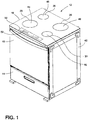
FIG. 1 is a top perspective view of a cooktop of the present disclosure coupled to an appliance; -
FIG. 2 is a top plan view of a cooktop of the present disclosure that has a glass-ceramic surface; -
FIG. 3 is a cross-sectional view of the cooktop ofFIG. 2 taken along lines III-III; -
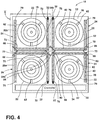
FIG. 4 is a top plan view of the cooktop ofFIG. 2 with the glass-ceramic surface removed to illustrate a plurality of coils and an indicator assembly of the present disclosure that has a first deflector and a second deflector; -
FIG. 5 is an enlarged partial top plan view of the indicator assembly ofFIG. 4 taken at area V; -
FIG. 6 is a top plan view of a cooktop of the present disclosure with a light path that defines activated cooking areas; -
FIG. 7 is a top plan view of a plurality of coils and an indicator assembly of the present disclosure that has a barrier member; and -
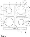
FIG. 8 is a top plan view of a cooktop of the present disclosure with light paths that define activated cooking areas. - The components in the figures are not necessarily to scale, emphasis instead being placed upon illustrating the principles described herein.
- The present illustrated embodiments reside primarily in combinations of apparatus components related to an indicator assembly for a cooktop. Accordingly, the apparatus components have been represented, where appropriate, by conventional symbols in the drawings, showing only those specific details that are pertinent to understanding the embodiments of the present disclosure so as not to obscure the disclosure with details that will be readily apparent to those of ordinary skill in the art having the benefit of the description herein. Further, like numerals in the description and drawings represent like elements.
- For purposes of description herein, the terms "upper," "lower," "right," "left," "rear," "front," "vertical," "horizontal," and derivatives thereof shall relate to the disclosure as oriented in
FIG. 1 . Unless stated otherwise, the term "front" shall refer to the surface of the element closer to an intended viewer, and the term "rear" shall refer to the surface of the element further from the intended viewer. However, it is to be understood that the disclosure may assume various alternative orientations, except where expressly specified to the contrary. It is also to be understood that the specific devices and processes illustrated in the attached drawings, and described in the following specification are simply exemplary embodiments of the inventive concepts defined in the appended claims. Hence, specific dimensions and other physical characteristics relating to the embodiments disclosed herein are not to be considered as limiting, unless the claims expressly state otherwise. - The terms "including," "comprises," "comprising," or any other variation thereof, are intended to cover a non-exclusive inclusion, such that a process, method, article, or apparatus that comprises a list of elements does not include only those elements but may include other elements not expressly listed or inherent to such process, method, article, or apparatus. An element proceeded by "comprises a ..." does not, without more constraints, preclude the existence of additional identical elements in the process, method, article, or apparatus that comprises the element.
- Referring to
FIGS. 1-8 ,reference numeral 10 generally designates a cooktop for anappliance 12 that includes abody 14 that has asupport surface 16. Acooking surface 18 is operably coupled to thebody 14 and which can have and/or define a plurality ofindicia 20. A plurality ofcoils 22 are operably coupled to thesupport surface 16 of thebody 14. The plurality ofcoils 22 correspond with the plurality ofindicia 20 defined by thecooking surface 18. Anindicator assembly 24 is operably coupled to thesupport surface 16 of thebody 14. Theindicator assembly 24 includesreflective members 26 disposed on thesupport surface 16 proximate to the plurality ofcoils 22.Lasers 32 are operably coupled to thesupport surface 16 and are disposed proximate thereflective members 26. Acontroller 34 is operably coupled to theindicator assembly 24 and is configured to activate thelasers 32 relative to thereflective members 26. - Referring to
FIGS. 1-3 , thecooktop 10 includes a glass-ceramic surface coupled to thesupport surface 16 of thecooktop 10 through which theindicator assembly 24 is selectively visible, as described below. Thecooktop 10 is illustrated as being disposed on theappliance 12 proximate to adoor 40 and coupled to anappliance body 42. As illustrated, theappliance 12 includes, in addition to thedoor 40 and theappliance body 42, awarming drawer 44 positioned beneath thedoor 40 of theappliance 12. Although thecooktop 10 is illustrated as being coupled to theappliance body 42 of theappliance 12, it is also contemplated that thecooktop 10 may be separate from theappliance 12, such that thecooktop 10 can be disposed on a countertop surface. For example, thebody 14 of thecooktop 10 can be coupled to a countertop surface to independently support thecooktop 10 from theappliance 12. - It is generally contemplated that the
cooktop 10 is an induction cooktop, such that each of thecoils 22 is associated with aburner area 46 that generates a constantly changing electromagnetic field configured to interact with a metal cooking utensil placed on theburner area 46. However, it is also contemplated that theindicator assembly 24 described herein may be used in other cooktops, such as gas-operated cooktops. Theburner area 46 may be at least partially defined by the plurality ofindicia 20 defined along thecooking surface 18 of thecooktop 10. It is generally contemplated that thecooking surface 18 may be a glass-ceramic surface, such that theindicator assembly 24 can be selectively visible through thecooking surface 18, described further below. Theindicia 20 generally indicate the position of eachcoil 22 beneath thecooking surface 18, or a position on which a superposed cooking utensil should be centered. While theindicia 20 indicates the location of eachburner area 46, theindicator assembly 24 indicates whichburner area 46 is in use, as described below. - With further reference to
FIGS. 1-3 , thecooktop 10 includes auser interface 50 disposed on and operably coupled to thecooking surface 18. Theuser interface 50 is positioned proximate to thedoor 40 of theappliance 12 and is operably coupled to thecontroller 34 to provide controls for a user to operate thecooktop 10. Theuser interface 50 includestactile indicia 52 communicatively coupled to thecontroller 34 to activate at least one of thecoils 22 and simultaneously activate theindicator assembly 24. For example, theuser interface 50 is also operably coupled with theindicator assembly 24 via thecontroller 34 to operate thelasers 32, as described in more detail below. The coupling of theindicator assembly 24 with theuser interface 50 further defines the selectedburner area 46, described in further detail below. - Referring now to
FIGS. 3-6 , aspace 60 is defined between thesupport surface 16 and thecooking surface 18 in which theindicator assembly 24 and the plurality ofcoils 22 are disposed. Thespace 60 is typically a height sufficient to contain thecoils 22 and theindicator assembly 24, but is compact to minimize the bulk of theoverall cooktop 10. Each of the plurality ofcoils 22 is coupled to thesupport surface 16 via retention clips 62, and eachcoil 22 can be surrounded by one of thereflective members 26 to generally define a U-shaped configuration around eachcoil 22. Thereflective members 26 are disposed on and coupled to thesupport surface 16. It is generally contemplated that thereflective members 26 are coupled to thesupport surface 16 via an adhesive 64 disposed on abottom surface 66 of thereflective members 26. Thebottom surface 66 of thereflective members 26 is configured to adhere thereflective members 26 to thesupport surface 16 via the adhesive 64. Atop surface 68 of thereflective members 26 is formed from a reflective material configured to reflect light, as described in more detail below. For example, thereflective members 26 can be formed from strips of reflective tape, such that thebottom surface 66 of thereflective members 26 includes the adhesive 64 that is configured to adhere to thesupport surface 16 and thetop surface 68 includes the reflective material. Additionally or alternatively, thereflective members 26 may be coupled to thesupport surface 16 via other fastening methods, such as separate adhesive strips, screws, magnets, and other practicable fasteners. - The
reflective members 26, as illustrated inFIG. 4 , include afirst bend 70 and asecond bend 72. It is generally contemplated that thefirst bend 70 and thesecond bend 72 are generally orthogonal. Additionally or alternatively, it is also contemplated that thefirst bend 70 and thesecond bend 72 may be curved, rounded, or any other orientation to be disposed around thecoils 22. As illustrated inFIG. 4 , thereflective members 26 each include first and secondlateral portions medial portion 76 extending between thelateral portions first bend 70 and thesecond bend 72 are defined where thelateral portions medial portion 76, respectively. Stated differently, themedial portion 76 of eachreflective member 26 extends between thelateral portions first bend 70 and thesecond bend 72 of each of thereflective members 26. Thereflective members 26 may generally cooperate with theindicia 20 disposed on thecooking surface 18 to illuminate the selectedburner area 46. For example, the selectedburner area 46 indicated by one of theindicia 20 can be illuminated by theindicator assembly 24, described in further detail below. - With specific reference to
FIG. 5 , one of thelasers 32 is positioned on afirst end 78 of the illustratedreflective member 26, such that alight path 80 of thelaser 32 is reflected by thereflective member 26. Additionally or alternatively, thelaser 32 may be positioned on asecond end 79 of thereflective member 26 to define thelight path 80. It is generally contemplated that thelasers 32 may be referred to as an illumination feature, such that afirst illumination feature 32 may be coupled to a firstreflective member 26a and asecond illumination feature 32 may be coupled to a secondreflective member 26b. Thelight path 80 of thelaser 32 is enhanced by thereflective member 26 to transmit thelight path 80 through thecooking surface 18 of thecooktop 10 to define an activatedcooking area 82, described below. Thelight path 80 is reflected by thereflective member 26, such that thelight path 80 of theindicator assembly 24 is visible through thecooking surface 18 to illuminate the activatedcooking area 82. - Referring still to
FIGS. 4-6 , thelaser 32 is operably coupled to thecontroller 34 of theuser interface 50 to selectively display thelight path 80. Thecontroller 34 is configured to receive a signal from theuser interface 50 as a result of the user selecting one of theburner areas 46 for use. Upon selection of one of theburner areas 46, thecontroller 34 activates at least onelaser 32 to disperse thelight path 80 along the respectivereflective member 26. Stated differently, the activation of theindicator assembly 24 by thecontroller 34 indicates the activatedcooking area 82 by outlining theburner area 46 with thelight path 80 of thelaser 32. - As mentioned above, the
indicator assembly 24 includes thereflective members 26 and thelasers 32. It is also contemplated that theindicator assembly 24 can include afirst deflector 84 and asecond deflector 86, as illustrated inFIGS. 4 and5 . The first andsecond deflectors indicator assembly 24 are positioned on the first andsecond bends reflective members 26 to direct thelight path 80 along the respectivereflective member 26 and define the activatedcooking area 82. Stated differently, thefirst deflector 84 and thesecond deflector 86 help to further define the activatedcooking area 82 by deflecting thelight path 80 of thelaser 32 along thereflective member 26. - As illustrated in
FIG. 5 , thefirst deflector 84 is coupled to thesupport surface 16 and is disposed on thefirst bend 70 of eachreflective member 26. For example, thereflective members 26 can include a firstreflective member 26a and a secondreflective member 26b. A first portion 84a of thefirst deflector 84 is disposed on thefirst bend 70 of the firstreflective member 26a, and asecond portion 84b of thefirst deflector 84 can be disposed on thefirst bend 70 of thesecond reflector 26b. Similarly, thesecond deflector 86 is coupled to thesupport surface 16 and is disposed on thesecond bend 72 of eachreflective member 26. The first andsecond deflectors light path 80 of eachlaser 32, described below. In addition, the first andsecond deflectors space 60 defined between thesupport surface 16 and thecooking surface 18 while maintaining the compact construction of thecooktop 10. Thefirst deflector 84 and thesecond deflector 86 are depicted as separate deflectors positioned along thereflective members 26. - For example, the
first deflector 84 is illustrated inFIG. 4 as being simultaneously disposed on thefirst bend 70 for each of thereflective members 26, such that thefirst deflector 84 has a box-like configuration. In this configuration, thefirst deflector 84 is centrally disposed on acentral portion 88 of thesupport surface 16 and disposed on eachfirst bend 70 of eachreflective member 26. Thesecond deflector 86 is depicted inFIG. 4 as being an L-shaped deflector positioned on thesecond bend 72 of each of thereflective members 26, such that thesecond deflector 86 is simultaneously positioned on thesecond bend 72 of two of thereflective members 26. As depicted, there are multiplesecond deflectors 86 disposed on thesupport surface 16, such that there is onesecond deflector 86 for every tworeflective members 26. Additionally or alternatively, eachfirst deflector 84 and eachsecond deflector 86 may be separately disposed on eachreflective member 26, such that the first andsecond deflectors - With further reference to
FIGS. 4-6 , thelaser 32 is disposed on thefirst end 78 of thereflective member 26 and is directed toward thefirst deflector 84 located at thefirst bend 70 of thereflective member 26. As disclosed herein, the first andsecond deflectors light path 80 of thelaser 32 is reflected and/or deflected by the mirrored surface of thefirst deflector 84 along themedial portion 76 of thereflective member 26 toward thesecond deflector 86 at thesecond bend 72 of thereflective member 26. Thesecond deflector 86 similarly reflects thelight path 80 of thelaser 32 along one of thelateral portions reflective member 26 toward thesecond end 79 of thereflective member 26. Thelight path 80 that is reflected by thefirst deflector 84 and/or thesecond deflector 86 is reflected at the same angle at which thelight path 80 first contacts either of thefirst deflector 84 or thesecond deflector 86. This reflection may also be referred to as adeflection angle 90 of thelight path 80 as thelight path 80 is deflected, or redirected, by the first andsecond deflectors - The
deflection angle 90 of thelight path 80 is defined as the angle taken between thelight path 80 along one of thelateral portions reflective member 26 and thelight path 80 reflected off of the respectivefirst deflector 84 orsecond deflector 86 along themedial portion 76 of thereflective member 26. Stated differently, thelaser 32 projects thelight path 80 along one of thelateral portions reflective member 26 toward thefirst deflector 84, and thelight path 80 is deflected by thefirst deflector 84 along themedial portion 76 of thereflective member 26 toward thesecond deflector 86. Thesecond deflector 86 can then deflect thelight path 80 again along thelateral portion reflective member 26. The deflection angles 90 are defined by the point in which thelight path 80 is deflected by each of the first andsecond deflectors - Referring still to
FIGS. 4-6 , the deflection angles 90 of thelight path 80 as reflected by the first andsecond deflectors indicator assembly 24 to illuminate the activatedcooking area 82, as illustrated inFIG. 6 . Although the deflection angles 90 are depicted as an approximately 90-degree angle, it is generally contemplated that the first andsecond deflectors indicator assembly 24 may project a different shape while still indicating the activatedcooking area 82. As mentioned, thelight path 80 of thelaser 32 is deflected at thedeflection angle 90 defined by each of thefirst deflector 84 and thesecond deflector 86. Thedeflection angle 90 of theindicator assembly 24 further defines the shape of theindicator assembly 24 around thecoil 22 to illuminate the activatedcooking area 82. - With reference now to
FIGS. 7 and8 , thereflective members 26 are each depicted as a single reflective strip disposed in a cross-formation along thesupport surface 16, such that a singlereflective member 26 of theindicator assembly 24 is disposed between eachcoil 22. As set forth herein, thelaser 32 is disposed on thefirst end 78 of thereflective members 26. Thesecond end 79 of each of thereflective members 26 extends toward thecentral portion 88 of thesupport surface 16. As compared to thelight path 80 described with respect toFIGS. 4-6 , thelight path 80 depicted inFIGS. 7 and8 is linear, such that thelaser 32 directs thelight path 80 directly from thefirst end 78 to thesecond end 79 of each of thereflective members 26. Thelight path 80 is ultimately obstructed by abarrier member 100 that is disposed on thecentral portion 88 of thesupport surface 16. - The
barrier member 100 is centrally disposed on thesupport surface 16 with thereflective member 26 extending toward each side of thebarrier member 100. Thebarrier member 100 is typically formed from a light-absorbing and heat resistant material, such that thebarrier member 100 absorbs thelight path 80 from thelaser 32 while being able to withstand the heat of thecoils 22. The position of thereflective members 26 in a cross-formation around thebarrier member 100 defines the light pattern of theindicator assembly 24 in the depicted construction illustrated inFIG. 8 . - With further reference to
FIGS. 7 and8 , thelaser 32 is positioned on thefirst end 78 of each of thereflective members 26 and is directed toward thebarrier member 100. Thelight path 80 is illuminated along thereflective member 26 and visible through thecooking surface 18, while being absorbed or otherwise obstructed by thebarrier member 100 proximate to thesecond end 79 of thereflective members 26. Thebarrier member 100 defines a separated appearance of the activatedcooking areas 82, such that thereflective members 26 are oriented with thebarrier member 100 defining agap 102 between thesecond end 79 of eachreflective member 26. Thegap 102 is defined regardless of how many of theburner areas 46 are selected for use, such that thegap 102 can be defined by the selection of any one of theburner areas 46 alone or in combination. In the configuration depicted inFIGS. 7 and8 , two of thelasers 32 are activated by thecontroller 34 to illuminate the activatedcooking area 82, as compared to thelight path 80 of asingle laser 32 being deflected to identify the activatedcooking area 82 as described with respect toFIGS. 4-6 . - The configuration depicted in
FIG. 8 is achieved by the user selecting theburner area 46 via thetactile indicia 52 on theuser interface 50, and thecontroller 34 communicating with theindicator assembly 24 to activate the twolasers 32 adjacent to the selectedburner area 46. Thelight path 80 from each of the two activatedlasers 32 is directed toward thebarrier member 100. Thebarrier member 100 absorbs the light emitted by each of thelasers 32 to define the segmented appearance of theindicator assembly 24 on thecooking surface 18. As illustrated inFIG. 8 , two sides of the activatedcooking area 82 are illuminated by theindicator assembly 24 to identify whichburner area 46 the user selected. - Referring again to
FIGS. 1-8 , theindicator assembly 24 allows a user to quickly and easily identify whichburner area 46 is selected for use.Induction cooktops 10, in particular, provide minimal indication of the activatedcooking area 82, such that theindicia 20 are typically one of the primary identifiers of the location of thecoils 22 beneath thecooking surface 18. Accordingly, theindicator assembly 24 assists the user to readily identify a particular activatedcooking area 82 to distinguish the selectedburner area 46 from thenon-selected burner areas 46. The various configurations of theindicator assembly 24 allow the user to have varying design construction for illuminating the activatedcooking area 82. For example, theindicator assembly 24 may include the first andsecond deflectors indicator assembly 24. Alternatively, theindicator assembly 24 may incorporate thebarrier member 100 to define the segmented configuration of theindicator assembly 24. In either configuration, theindicator assembly 24 helps the user easily identify theburner area 46 selected by the user. It is also contemplated that thebarrier member 100 may be used in combination with thereflective members 26 illustrated inFIGS. 4-6 . - The present disclosure disclosed herein is further summarized in the following paragraphs and is further characterized by combinations of any and all of the various aspects described therein.
- According to one aspect of the present disclosure, a cooktop for an appliance includes a body that has a support surface. A cooking surface is operably coupled to the body and having and/or defining a plurality of indicia. A plurality of coils are coupled to the support surface of the body. The plurality of coils correspond with the plurality of indicia defined on and/or by the cooking surface. An indicator assembly is operably coupled to the support surface of the body. The indicator assembly includes reflective members that are disposed on the support surface proximate to the plurality of coils and lasers are operably coupled to the support surface and are disposed proximate the reflective members. A controller is operably coupled to the indicator assembly and is configured to activate the lasers relative to the reflective members.
- According to another aspect, lasers define a light path proximate each reflective member.
- According to another aspect, a cooktop further includes a barrier member that is centrally disposed on a support surface of a body proximate to an end of each reflective member.
- According to another aspect, each reflective member includes a first end and a second end, and a first bend and a second bend are defined between the first end and the second end of each of the reflective members.
- According to another aspect, an indicator assembly further includes a first deflector and a second deflector, and the first deflector is disposed on each reflective member at a first bend and the second deflector is disposed on each of the reflective members at a second bend.
- According to another aspect, an indicator assembly is selectively visible through a cooking surface to define an activated cooking area.
- According to another aspect, a controller is configured to activate lasers of an indicator assembly to define an activated cooking area, and the controller is communicatively coupled to a plurality of coils to activate at least one of the lasers to define the activated cooking area of the cooking surface.
- According to another aspect of the present disclosure, an indicator assembly for a cooktop includes a support surface. Reflective members are operably coupled to the support surface. An illumination feature is operably coupled to a first end of each of the reflective members and define a light path along each of the reflective members. A barrier member is centrally disposed on the support surface proximate a second end of each of the reflective members.
- According to another aspect, reflective members at least partially define a cooking area and are configured to be disposed around coils disposed on a support surface.
- According to another aspect, a light path defined by an illumination feature extends along each reflective member and is configured to be obstructed by a barrier member.
- According to another aspect, reflective members include a first reflective member and a second reflective member, and a first illumination feature is coupled to the first reflective member and a second illumination feature is coupled to the second reflective member.
- According to another aspect, a light path defined by a first illumination feature along a first reflective member and the light path defined by a second illumination feature along a second reflective member define an activated cooking area.
- According to another aspect, a light path defined by a first illumination feature and a second illumination feature is obstructed by a barrier member to further define an activated cooking area.
- According to another aspect of the present disclosure, an indicator assembly for a cooktop includes a support surface. Reflective members are disposed on the support surface and have a first end and a second end. Each of the reflective members has a first bend and a second bend that are defined between the first end and the second end of each of the reflective members. A first deflector is disposed on the first bend of each of the reflective members. A second deflector is disposed on the second bend of each of the reflective members. An illumination feature is operably coupled to each of the reflective members and define a light path proximate each of the reflective members.
- According to another aspect, each reflective member includes first and second lateral portions and a medial portion defined therebetween. A light path defined by an illumination feature is altered by a first deflector to extend along the medial portion of each of the reflective member and is altered by a second deflector to extend along at least one of the first and second lateral portions of each of the reflective members to define an activated cooking area.
- According to another aspect, a first deflector and a second deflector comprise a reflective material configured to alter a light path defined by an illumination feature to define an activated cooking area.
- According to another aspect, a first deflector is centrally disposed on a support surface and is operably coupled to a first bend of each reflective member.
- According to another aspect, a deflection angle is defined by an alteration of a light path, and the deflection angle is defined by the light path and first and second deflectors to define a U-shape.
- According to another aspect, reflective members include a first reflective member and a second reflective member. A first deflector includes a first portion disposed on a first bend of the first reflective member and a second portion disposed on a first bend of the second reflective member.
- According to another aspect, an indicator assembly further includes a controller that is configured to activate an illumination feature to selectively define an activated cooking area along at least one of the reflective members.
Claims (15)
- A cooktop (10) for an appliance (12), comprising:a body (14) having a support surface (16);a cooking surface (18) operably coupled to the body (14);a plurality of coils (22) operably coupled to the support surface (16) of the body (14);an indicator assembly (24) operably coupled to the support surface (16) of the body (14), the indicator assembly (24) including:reflective members (26) disposed on the support surface (16) proximate to the plurality of coils (22); andlasers (32) operably disposed proximate the reflective members (26) and defining a light path (80); anda controller (34) operably coupled to the indicator assembly (24) and configured to activate the lasers (32) relative to the reflective members (26).
- The cooktop (10) of claim 1, wherein the indicator assembly (24) is selectively visible through the cooking surface (18) to define an activated cooking area (82).
- The cooktop (10) of claim 2, wherein the controller (34) is configured to activate the lasers (32) of the indicator assembly (24) to define the activated cooking area (82), and wherein the controller (34) is communicatively coupled to the plurality of coils (22) to activate at least one of the lasers (32) to define the activated cooking area (82) of the cooking surface (18).
- The cooktop (10) of any one of claims 1-3, further comprising:
a barrier member (100) centrally disposed on the support surface (16) of the body (14) proximate to an end of each of the reflective members (26). - The cooktop (10) of claim 4, wherein the light path (80) defined by each of the lasers (32) is obstructed by the barrier member (100) to further define the activated cooking area (82).
- The cooktop (10) of either one of claims 4 and 5, wherein the light path (80) defined by the lasers (32) extends along each of the reflective members (26) and is configured to be obstructed by the barrier member (100).
- The cooktop (10) of any one of claims 1-6, wherein each of the reflective members (26) includes a first end (78) and a second end (79), and wherein a first bend (70) and a second bend (72) are defined between the first end (78) and the second end (79) of each of the reflective members (26).
- The cooktop (10) of claim 7, wherein the indicator assembly (24) further includes a first deflector (84) and a second deflector (86), and wherein the first deflector (84) is disposed on each of the reflective members (26) at the first bend (70) and the second deflector (86) is disposed on each of the reflective members (26) at the second bend (72).
- The cooktop (10) of claim 8, wherein the first deflector (84) is centrally disposed on the support surface (16) and operably coupled to the first bend (70) of each of the reflective members (26).
- The cooktop (10) of claim 8, wherein the first deflector (84) and the second deflector (86) comprise a reflective material configured to alter the light path (80) defined by the lasers (32) to define the activated cooking area (82).
- The cooktop (10) of any one of claims 8-10, wherein each of the reflective members (26) includes first and second lateral portions (74a, 74b) and a medial portion (76) defined therebetween.
- The cooktop (10) of claim 11, wherein the light path (80) defined by the lasers (32) is altered by the first deflector (84) to extend along the medial portion (76) of each of the reflective members (26) and is altered by the second deflector (86) to extend along at least one of the first and second lateral portions (74a, 74b) of each of the reflective members (26).
- The cooktop (10) of any one of claims 8-12, wherein a deflection angle (90) is defined by an alteration of the light path (80), and wherein the deflection angle (90) is defined by the light path (80) and the first and second deflectors (84, 86) to define a U-shape.
- The cooktop (10) of any one of claims 1-13, wherein the reflective members (26) include a first reflective member (26a) and a second reflective member (26b), and wherein a first laser is coupled to the first reflective member (26a) and a second laser is coupled to the second reflective member (26b).
- The cooktop (10) of claim 14, wherein a light path (80) defined by the first laser along the first reflective member (26a) and a light path (80) defined by the second laser along the second reflective member (26b) define the activated cooking area (82).
Applications Claiming Priority (2)
| Application Number | Priority Date | Filing Date | Title |
|---|---|---|---|
| US202063017727P | 2020-04-30 | 2020-04-30 | |
| US17/227,434 US20210341151A1 (en) | 2020-04-30 | 2021-04-12 | Indicator assembly |
Publications (1)
| Publication Number | Publication Date |
|---|---|
| EP3904771A1 true EP3904771A1 (en) | 2021-11-03 |
Family
ID=75728771
Family Applications (1)
| Application Number | Title | Priority Date | Filing Date |
|---|---|---|---|
| EP21171043.9A Withdrawn EP3904771A1 (en) | 2020-04-30 | 2021-04-28 | Cooktop with indicator assembly |
Country Status (2)
| Country | Link |
|---|---|
| US (1) | US20210341151A1 (en) |
| EP (1) | EP3904771A1 (en) |
Families Citing this family (2)
| Publication number | Priority date | Publication date | Assignee | Title |
|---|---|---|---|---|
| USD980013S1 (en) * | 2019-06-28 | 2023-03-07 | Whirlpool Corporation | Cooking appliance |
| JP7818209B2 (en) * | 2022-06-14 | 2026-02-20 | パナソニックIpマネジメント株式会社 | induction heating cooker |
Citations (5)
| Publication number | Priority date | Publication date | Assignee | Title |
|---|---|---|---|---|
| JP2003197357A (en) * | 2001-12-28 | 2003-07-11 | Sanyo Electric Co Ltd | Electromagnetic cooker |
| US20130286630A1 (en) * | 2010-11-04 | 2013-10-31 | Eurokera S.N.C. | Light-emitting, glass-ceramic article |
| DE102012212350A1 (en) * | 2012-07-13 | 2014-01-16 | E.G.O. Elektro-Gerätebau GmbH | Hob for domestic use, has lens and deflector that are configured for deflecting light beams arranged on underside of hob plate in beam path |
| EP2950614A1 (en) * | 2014-05-30 | 2015-12-02 | Samsung Electronics Co., Ltd. | Cooking apparatus |
| DE102015222719A1 (en) * | 2015-11-18 | 2017-05-18 | E.G.O. Elektro-Gerätebau GmbH | Cooking appliance with display device and method for display on a cooking appliance |
-
2021
- 2021-04-12 US US17/227,434 patent/US20210341151A1/en not_active Abandoned
- 2021-04-28 EP EP21171043.9A patent/EP3904771A1/en not_active Withdrawn
Patent Citations (5)
| Publication number | Priority date | Publication date | Assignee | Title |
|---|---|---|---|---|
| JP2003197357A (en) * | 2001-12-28 | 2003-07-11 | Sanyo Electric Co Ltd | Electromagnetic cooker |
| US20130286630A1 (en) * | 2010-11-04 | 2013-10-31 | Eurokera S.N.C. | Light-emitting, glass-ceramic article |
| DE102012212350A1 (en) * | 2012-07-13 | 2014-01-16 | E.G.O. Elektro-Gerätebau GmbH | Hob for domestic use, has lens and deflector that are configured for deflecting light beams arranged on underside of hob plate in beam path |
| EP2950614A1 (en) * | 2014-05-30 | 2015-12-02 | Samsung Electronics Co., Ltd. | Cooking apparatus |
| DE102015222719A1 (en) * | 2015-11-18 | 2017-05-18 | E.G.O. Elektro-Gerätebau GmbH | Cooking appliance with display device and method for display on a cooking appliance |
Also Published As
| Publication number | Publication date |
|---|---|
| US20210341151A1 (en) | 2021-11-04 |
Similar Documents
| Publication | Publication Date | Title |
|---|---|---|
| US6223986B1 (en) | Aiming aid for optical data reading | |
| US20210341151A1 (en) | Indicator assembly | |
| US7041945B2 (en) | Induction heater for cooking | |
| US5448036A (en) | Cooktop with illuminated cooktop temperature indicators controlled by the hot plates | |
| KR20090091439A (en) | Electric cooker and induction coil unit used in it | |
| CN107690833B (en) | Cooking appliance comprising a heating zone lighting device | |
| US11429230B2 (en) | Motorist user interface sensor | |
| USD360146S (en) | Thermostat housing | |
| KR20180057479A (en) | Induction-heating cooking apparatus and cooking information display method thereof | |
| EP4095456B1 (en) | Air-processing apparatus | |
| EP2330355B1 (en) | Cooking top and method for controlling it | |
| US6817726B2 (en) | Lighting system | |
| JP2002531931A (en) | Touch sensing switch | |
| JP5523232B2 (en) | Cooker | |
| CN108063613A (en) | The close switch of holography | |
| JP2015094522A (en) | Temperature detection device for heating cooker | |
| JP3677233B2 (en) | Optical reader | |
| JP4733891B2 (en) | Anti-glare transparent screen for illuminant | |
| US20230409134A1 (en) | Operating device for a household appliance comprising an integrated touch-sensitive operating ring in an operating depression | |
| JPH0771785A (en) | Air conditioner | |
| JP2009099365A (en) | Electromagnetic cooker | |
| JPH08203324A (en) | Lighting system for show-case | |
| JP5819155B2 (en) | Cooker | |
| AU2018391838B2 (en) | Surface light source assembly and refrigerator having the same | |
| JP4254360B2 (en) | Drop-in cooker |
Legal Events
| Date | Code | Title | Description |
|---|---|---|---|
| PUAI | Public reference made under article 153(3) epc to a published international application that has entered the european phase |
Free format text: ORIGINAL CODE: 0009012 |
|
| STAA | Information on the status of an ep patent application or granted ep patent |
Free format text: STATUS: THE APPLICATION HAS BEEN PUBLISHED |
|
| AK | Designated contracting states |
Kind code of ref document: A1 Designated state(s): AL AT BE BG CH CY CZ DE DK EE ES FI FR GB GR HR HU IE IS IT LI LT LU LV MC MK MT NL NO PL PT RO RS SE SI SK SM TR |
|
| B565 | Issuance of search results under rule 164(2) epc |
Effective date: 20210906 |
|
| STAA | Information on the status of an ep patent application or granted ep patent |
Free format text: STATUS: REQUEST FOR EXAMINATION WAS MADE |
|
| 17P | Request for examination filed |
Effective date: 20220503 |
|
| RBV | Designated contracting states (corrected) |
Designated state(s): AL AT BE BG CH CY CZ DE DK EE ES FI FR GB GR HR HU IE IS IT LI LT LU LV MC MK MT NL NO PL PT RO RS SE SI SK SM TR |
|
| STAA | Information on the status of an ep patent application or granted ep patent |
Free format text: STATUS: THE APPLICATION HAS BEEN WITHDRAWN |
|
| 18W | Application withdrawn |
Effective date: 20221006 |