EP3904753A1 - Bracket, light module including the same and method for manufacturing the same - Google Patents
Bracket, light module including the same and method for manufacturing the same Download PDFInfo
- Publication number
- EP3904753A1 EP3904753A1 EP20172376.4A EP20172376A EP3904753A1 EP 3904753 A1 EP3904753 A1 EP 3904753A1 EP 20172376 A EP20172376 A EP 20172376A EP 3904753 A1 EP3904753 A1 EP 3904753A1
- Authority
- EP
- European Patent Office
- Prior art keywords
- light emitting
- bracket
- base plate
- side plate
- side edge
- Prior art date
- Legal status (The legal status is an assumption and is not a legal conclusion. Google has not performed a legal analysis and makes no representation as to the accuracy of the status listed.)
- Granted
Links
Images



Classifications
-
- F—MECHANICAL ENGINEERING; LIGHTING; HEATING; WEAPONS; BLASTING
- F21—LIGHTING
- F21S—NON-PORTABLE LIGHTING DEVICES; SYSTEMS THEREOF; VEHICLE LIGHTING DEVICES SPECIALLY ADAPTED FOR VEHICLE EXTERIORS
- F21S4/00—Lighting devices or systems using a string or strip of light sources
- F21S4/20—Lighting devices or systems using a string or strip of light sources with light sources held by or within elongate supports
- F21S4/22—Lighting devices or systems using a string or strip of light sources with light sources held by or within elongate supports flexible or deformable, e.g. into a curved shape
-
- F—MECHANICAL ENGINEERING; LIGHTING; HEATING; WEAPONS; BLASTING
- F21—LIGHTING
- F21V—FUNCTIONAL FEATURES OR DETAILS OF LIGHTING DEVICES OR SYSTEMS THEREOF; STRUCTURAL COMBINATIONS OF LIGHTING DEVICES WITH OTHER ARTICLES, NOT OTHERWISE PROVIDED FOR
- F21V15/00—Protecting lighting devices from damage
- F21V15/01—Housings, e.g. material or assembling of housing parts
-
- F—MECHANICAL ENGINEERING; LIGHTING; HEATING; WEAPONS; BLASTING
- F21—LIGHTING
- F21V—FUNCTIONAL FEATURES OR DETAILS OF LIGHTING DEVICES OR SYSTEMS THEREOF; STRUCTURAL COMBINATIONS OF LIGHTING DEVICES WITH OTHER ARTICLES, NOT OTHERWISE PROVIDED FOR
- F21V17/00—Fastening of component parts of lighting devices, e.g. shades, globes, refractors, reflectors, filters, screens, grids or protective cages
- F21V17/10—Fastening of component parts of lighting devices, e.g. shades, globes, refractors, reflectors, filters, screens, grids or protective cages characterised by specific fastening means or way of fastening
- F21V17/16—Fastening of component parts of lighting devices, e.g. shades, globes, refractors, reflectors, filters, screens, grids or protective cages characterised by specific fastening means or way of fastening by deformation of parts; Snap action mounting
- F21V17/164—Fastening of component parts of lighting devices, e.g. shades, globes, refractors, reflectors, filters, screens, grids or protective cages characterised by specific fastening means or way of fastening by deformation of parts; Snap action mounting the parts being subjected to bending, e.g. snap joints
-
- F—MECHANICAL ENGINEERING; LIGHTING; HEATING; WEAPONS; BLASTING
- F16—ENGINEERING ELEMENTS AND UNITS; GENERAL MEASURES FOR PRODUCING AND MAINTAINING EFFECTIVE FUNCTIONING OF MACHINES OR INSTALLATIONS; THERMAL INSULATION IN GENERAL
- F16B—DEVICES FOR FASTENING OR SECURING CONSTRUCTIONAL ELEMENTS OR MACHINE PARTS TOGETHER, e.g. NAILS, BOLTS, CIRCLIPS, CLAMPS, CLIPS OR WEDGES; JOINTS OR JOINTING
- F16B7/00—Connections of rods or tubes, e.g. of non-circular section, mutually, including resilient connections
- F16B7/18—Connections of rods or tubes, e.g. of non-circular section, mutually, including resilient connections using screw-thread elements
- F16B7/182—Connections of rods or tubes, e.g. of non-circular section, mutually, including resilient connections using screw-thread elements for coaxial connections of two rods or tubes
-
- F—MECHANICAL ENGINEERING; LIGHTING; HEATING; WEAPONS; BLASTING
- F21—LIGHTING
- F21Y—INDEXING SCHEME ASSOCIATED WITH SUBCLASSES F21K, F21L, F21S and F21V, RELATING TO THE FORM OR THE KIND OF THE LIGHT SOURCES OR OF THE COLOUR OF THE LIGHT EMITTED
- F21Y2115/00—Light-generating elements of semiconductor light sources
- F21Y2115/10—Light-emitting diodes [LED]
Definitions
- the present invention relates to a field of lighting, and in particular to a bracket for assembling a flexible light emitting strip in a light module, a light module including the bracket, and a method for manufacturing the bracket.
- the flexible light emitting strip, the optical part and the bracket are assembled in a face-to-face way, which may leave gaps between the flexible light emitting strip and the optical part and result in inaccurate positioning of the flexible light emitting strip with respect to the optical part.
- the gaps and the inaccurate positioning may affect the light in-coupling efficiency from the flexible light emitting strip into the optical part, then affect the effect of optical processing, and thus finally affect the characteristic of light emitted out of the optical part.
- adhesive tape or glue or the like is applied between the flexible light emitting strip and the bracket to improve the positioning and fixing of the flexible light emitting strip.
- the gaps between the flexible light emitting strip and the optical part are difficult to be eliminated completely by applying adhesive tape or glue or the like as described above, so inaccurate positioning of the flexible light emitting strip still exists.
- the inventor of the present invention recognizes that the face-to-face contact between the flexible light emitting strip and the bracket needs to be changed.
- the face-to-face contact may be changed to a line-to-face contact and/or a dot-to-face contact.
- the contour surface of the top ends of the plurality of projections forms the actual surface supporting the flexible light emitting strip.
- each projection can be adjusted individually during an injection moulding process by adjustments of injection molds, the shape of the contour surface of the top ends of the plurality of projections can be changed, so as to achieve accurate positioning of the flexible light emitting strip.
- the bracket with a plurality of projections is convenient to be manufactured by an injection moulding process.
- a bracket for assembling a flexible light emitting strip in a light module comprises: a base plate, comprising a first side edge and a second side edge opposite to each other; a first side plate, located along the first side edge, extending from the base plate and comprising at least one first engagement member; and a second side plate, located along the second side edge, extending from the base plate, opposite to the first side plate and comprising at least one another first engagement member.
- the base plate, the first side plate and the second side plate form a groove, and the base plate comprises a plurality of projections on a surface inside the groove.
- the bracket is designed to be used in a light module to accurately position a flexible light emitting strip onto an optical part.
- the first engagement members on side plates of the bracket can be coupled with the corresponding engagement members on an optical part in order to offer a fastening structure.
- the projections on the base plate can abut and support the flexible light emitting strip at respective positions, in order to offer an accurate position of the light emitting strip with respect to the optical part, thus improving the light in-coupling efficiency into the optical part.
- the base plate, the first side plate and the second side plate are one-piece, wherein the base plate, the first side plate and the second side plate are formed integrally. It makes the bracket more robust and the manufacturing process thereof easier.
- the bracket can be manufactured by an injection moulding process using any suitable materials, such as plastic materials.
- each of the first side edge and the second side edge has a curvilinear shape.
- the shapes of the first side edge and the second side edge may define the shape of the bracket, which may be adapted to the desired shape of a light module comprising the bracket.
- first side edge and the second side edge are parallel to each other, and the first side plate and the second side plate are parallel to each other.
- the flexible light emitting strip may typically have a cross-section of rectangular shape, so that a pair of side plates parallel to each other may fit the flexible light emitting strip better and thus support it better.
- the projections on the base plate are ribs parallel to each other with each rib extending from the first side edge or the second side edge.
- each of the first side plate and the second side plate comprise a plurality of projections on a surface inside the groove.
- the projections on the first side plate are ribs parallel to each other with each rib extending from the first side edge
- the projections on the second side plate are ribs parallel to each other with each rib extending from the second side edge.
- Ribs parallel to each other can simplify the manufacturing process of the bracket as the ribs parallel to each other are easier to form or adjust than projections in irregular forms. Since the flexible light emitting strip may be flexed or bent in length, the ribs extending from a side edge of the base plate can abut the flexible light emitting strip at positions along its length, which can offer better support to the strip and facilitate the adaptation to its shape.
- each rib has a width ranging from 0.1 mm to 1 mm.
- each rib has a height ranging from 0.2 mm to 1 mm.
- each rib has an arc shape on its top surface.
- the ribs on the base plate, the first side plate and the second side plate have a distribution ranging from 100 to 200 ribs per meter along the first side edge or the second side edge.
- the width, height, shape of a rib or the distribution of the ribs may affect the effect of positioning the flexible light emitting strip towards the optical part and can be adjusted as required e.g. by adjusting the injection molds used in the manufacturing process of the bracket.
- a light module comprising: the bracket described above; the flexible light emitting strip, comprising a back surface and a light emitting surface opposite to each other, wherein the back surface has a shape corresponding to the base plate; and an optical part, comprising a first surface and a second surface opposite to each other, a first side surface and a second side surface opposite to each other.
- the first surface has a shape corresponding to the light emitting surface of the flexible light emitting strip.
- the first side surface of the optical part has at least one second engagement member corresponding to the at least one first engagement member on the first side plate of the bracket, and the second side surface of the optical part has at least one another second engagement member corresponding to the at least one another first engagement member on the second side plate of the bracket.
- the flexible light emitting strip is disposed in the groove with the back surface of the flexible light emitting strip contacting the projections on the base plate of the bracket, the flexible light emitting strip being sandwiched between the bracket and the optical part with the first surface of the optical part contacting the light emitting surface of the flexible light emitting strip and the projections on the base plate pressing the back surface of the flexible light emitting strip, such that the light emitting surface of the flexible light emitting strip contacts the first surface of the optical part at any place of the light emitting surface.
- Each of the first engagement members and a corresponding one of the second engagement members are coupled with each other.
- each of the another first engagement members and a corresponding one of the another second engagement members are coupled with each other.
- the flexible light emitting strip is a flexible LED light strip.
- a plurality of recesses are provided on the back surface of the flexible light emitting strip with each recess on the back surface corresponding to one of the projections on the base plate.
- the method comprises the steps of:
- Fig. 1 shows a bracket 100 according to an exemplary embodiment of the present invention in the form of a perspective view.
- the bracket 100 can be used for assembling a flexible light emitting strip in a light module, which will be explained in detail hereinafter.
- the bracket 100 includes a base plate 110, a first side plate 120a and a second side plate 120b.
- the base plate 110 includes a first side edge 110a and a second side edge 110b opposite to each other.
- the first side plate 120a and the second side plate 120b are located along the first side edge 110a and the second side edge 110b respectively, extending from the base plate 110 in the same direction and opposite to each other.
- the base plate 110, the first side plate 120a and the second side plate 120b together form a groove 130, which can be used to receive the flexible light emitting strip of the light module.
- the base plate 110, the first side plate 120a and the second side plate 120b may be formed to be one-piece by e.g. injection moulding using any suitable materials, such as plastic materials. In this situation, the first side plate 120a and the second side plate 120b may be extension parts on a surface of the base plate 110. Alternatively, the base plate 110, the first side plate 120a and the second side plate 120b may be formed as separate components, which may be combined together in any suitable way, for example, by bolts or screws.
- Each of the first side plate 120a and the second side plate 120b includes at least one first engagement member 121, which may be used for coupling with a corresponding second engagement member.
- the first engagement member 121 is an extension part on a surface of the first side plate 120a or the second side plate 120b facing away from the base plate, with a snap hole formed at a center of the extension part, through which the second engagement member like a snap tab may go, so that a snap-fit structure may be formed.
- the first engagement member 121 may be a snap tab
- the corresponding second engagement member may include a snap hole.
- first engagement member 121 may be any suitable type of engagement member, such as a bolt or a pin, as long as it can form a fastening structure with a corresponding second engagement member.
- first side plate 120a and the second side plate 120b may have different numbers of the first engagement members 121.
- the shape of the base plate 110 is defined by the first side edge 110a and the second side edge 110b thereof.
- the first side edge 110a and the second side edge 110b of the base plate 110 have a same curvilinear shape, and accordingly, the base plate 110 has a curved shape.
- the first side edge 110a and the second side edge 110b may also have a linear shape, and accordingly the base plate 110 may have a planar shape.
- one of the first side edge 110a and the second side edge 110b may have a curvilinear shape, and the other one may have a linear shape, or the first side edge 110a and the second side edge 110b may have different curvilinear shapes.
- the base plate 110 as well as the first and second side plates 120a, 120b can be made of flexible materials, so that they can be changed in shape as desired.
- first side edge 110a and the second side edge 110b are substantially parallel with each other, and the first side plate 120a and the second side plate 120b are substantially parallel with each other as well.
- first side edge 110a and the second side edge 110b may be nonparallel with each other.
- the first and second side plates 120a, 120b each extend in a plane substantially perpendicular to the surface of the base plate 110 to from the side walls of the groove 130.
- the base plate 110 includes a plurality of ribs 111 on a surface inside the groove 130.
- the ribs 111 on the base plate 110 are parallel to each other, and each of the ribs 111 extends from the first side edge 110a to the second side edge 110b.
- the ribs 111 may not extend across the whole groove 130. In this situation, at least some ribs 110 may extend along a part of the width of the groove 130. In some exemplary embodiments, some ribs 111 may extend from the first side edge 110a, and the other ribs 111 may extend from the second side edge 110b.
- the ribs 111 extend in a direction substantially perpendicular to the first side edge 110a or the second side edge 110b; however, in some exemplary embodiments, the ribs 111 may also extend in a direction not perpendicular to the first side edge 110a or the second side edge 110b.
- Fig. 5 it is a schematic enlarged view showing some details of the ribs 111 on the base plate 110. It can be clearly seen in Fig. 5 that with the ribs 111, the face-to-face contact between the base plate 110 and a corresponding contact surface of a flexible light emitting strip can be changed to a line-to-face contact, and thus, the contour surface of the top ends of the plurality of ribs 111 on the base plate 110 forms the actual surface supporting the flexible light emitting strip. Since one or more characteristics of the ribs 111, such as the size of a rib (i.e. the width W and/or height H of a rib, as shown in Fig.
- the shape of the top end of a rib and the distribution of ribs can be changed during an injection moulding process by adjusting injection molds, the shape of the contour surface can be changed accordingly, making the contour surface tightly contact the flexible light emitting strip without any gap existing between the flexible light emitting strip and an optical part.
- the ribs 111 on the base plate 110 may have a height H ranging from 0.2 mm to 1 mm, a width W ranging from 0.1 mm to 1 mm, an arc shape on each top surface thereof, and a distribution ranging from 100 to 200 ribs per meter along the first side edge 110a or the second side edge 110b.
- the width W of the rib 111 may be chosen to be close to the thickness of the base plate 110, which may facilitate the manufacture of the bracket 100 by an injection moulding process.
- the second side plate 120b also includes a plurality of ribs 111 on a surface inside the groove 130.
- the ribs 111 on the second side plate 120b are parallel to each other and extending from the second side edge 110b.
- the first side plate 120a may also include a plurality of ribs 111 on a surface inside the groove 130, and the ribs 111 on the first side plate 120a may be parallel to each other and extending from the first side edge 110a.
- the ribs 111 on the first side plate 120a and the second side plate 120b function like the ribs 111 on the base plate 110, so as to tightly contact the side surfaces of a flexible light emitting strip, which may further facilitate the accurate positioning of the flexible light emitting strip.
- the ribs 111 on the first side plate 120a and the second side plate 120b may also have a height H ranging from 0.2 mm to 1 mm, a width W ranging from 0.1 mm to 1 mm, an arc shape on each top surface thereof, and/or a distribution ranging from 100 to 200 ribs per meter along the first side edge 110a or the second side edge 110b.
- the ribs on the first side plate 120a and/or the second side plate 120b may have different characteristics from those of the ribs on the base plate 110.
- the ribs on the base plate 110, the first side plate 120a and/or the second side plate 120b may be replaced with projections in any appropriate forms, such as dots, pillars or the like, as long as the projections can change the face-to-face contact between the flexible light emitting strip and the bracket.
- the projections such as the ribs 111, may be formed in one-piece with the base plate 110, the first side plate 120a and the second side plate 120b respectively by e.g. injection moulding.
- the characteristics of the projections such as the size of each projection, the shape of the top end of each projection and the distribution of the projections, may be adjusted by different injection molds.
- the projections may be made of flexible materials as well.
- the bracket 100 is designed to be used in a light module to secure a flexible light emitting strip to an optical part.
- Fig. 2 schematically depicts a light module 200 in the form of an explosion view.
- the light module 200 includes the bracket 100 as shown in Fig. 1 , a flexible light emitting strip 210 and an optical part 220.
- the flexible light emitting strip 210 includes a back surface 211a and a light-emitting surface 211b opposite to each other.
- the flexible light emitting strip 210 may be received in the groove 130 of the bracket 100 and the back surface 211a of the flexible light emitting strip 210 may contact the ribs 111 on the base plate 110 of the bracket 100 when assembled.
- the back surface 211a may typically have a shape corresponding to the base plate 110, as shown in Fig. 2 .
- the flexible light emitting strip 210 may be a flexible LED light strip, such as a 3D LED. It may be changeable in shape and may include a plurality of light-emitting diodes (LEDs). However, the present invention is not limited thereto, and the flexible light emitting strip 210 may belong to other types of strips that may include a plurality of light emitting elements, such as organic light-emitting diodes (OLED), polymer light-emitting diodes (PLED), laser diodes, incandescent sources or fluorescent sources, which may emit light through the light emitting surface 211b.
- OLED organic light-emitting diodes
- PLED polymer light-emitting diodes
- laser diodes such as incandescent sources or fluorescent sources
- the optical part 220 includes a first surface 221a and a second surface 221b opposite to each other, as well as a first side surface 222a and a second side surface 222b opposite to each other.
- the first surface 221a may contact the light-emitting surface 211b of the flexible light emitting strip 210 when the optical part 220 is assembled with the flexible light emitting strip 210.
- the first surface 221a may typically have a shape corresponding to the light-emitting surface 211b of the flexible light emitting strip 210. Therefore, light from the flexible light emitting strip 210 may enter the optical part 220 through the first surface 221a and leave it through the second surface 221b.
- the first side surface 222a of the optical part 220 may have at least one second engagement member 223 corresponding to the at least one first engagement member 121 on the first side plate 120a of the bracket 100
- the second side surface 222b may have at least one second engagement member 223 corresponding to the at least one first engagement member 121 on the second side plate 120b of the bracket 100
- the distribution of the second engagement members 223 on the first side surface 222a and the second side surface 222b may be the same as that of the first engagement members 121 on the first side plate 120a and the second side plate 120b.
- the second engagement member 223 may be a snap tab formed on the first side surface 222a and the second side surface 222b, which may be matched with the first engagement member 121 including a snap hole as shown.
- the second engagement member 223 may belong to other types of engagement members such as a screwed hole that may be matched with a screw on the first and second side plates 120a, 120b of the bracket 100.
- the optical part 220 may be made of transparent or translucent materials and may offer some optical processing to light in-coupled.
- the optical part 220 may act as a collimator, a filter, a diffuser, a lens or the like, so that light emitted therefrom may have certain characteristics.
- Figs. 3A and 3B schematically illustrate the assembling process of the light module 200 shown in Fig. 2 .
- the bracket 100 may first be assembled with the flexible light emitting strip 210, so that the flexible light emitting strip 210 may be received in the groove 130 with the back surface 211a contacting the ribs 111 on the base plate 110.
- the flexible light emitting strip 210 may be a flexible LED light strip that comprises a plurality of LEDs.
- the assembly of the bracket 100 and the flexible light emitting strip 210 may be assembled with the optical part 220 to form the light module 200, in which the flexible light emitting strip 210 may be sandwiched between the bracket 100 and the optical part 220, with the light emitting surface 211b of the flexible light emitting strip 210 contacting the first surface 221a of the optical part 220.
- the ribs 111 on the base plate 100 can press the back surface 211a of the flexible light emitting strip 210, such that the light emitting surface 211b of the flexible light emitting strip 210 contacts the first surface 221a of the optical part 220 at any place of the light emitting surface 211b.
- each of the first engagement members 121 on the first side plate 120a of the bracket 100 and a corresponding one of the second engagement members 223 on the first side surface 222a of the optical part 220 are coupled with each other and form a fastening structure such as a snap-fit structure shown in Fig. 3B or a screwed fastening structure or the like; likewise, each of the first engagement members 121 on the second side plate 120b of the bracket 100 and a corresponding one of the second engagement members 223 on the second side surface 222b of the optical part 220 are also coupled with each other and form a fastening structure.
- the presence of projections on the bracket 100 changes the face-to-face contact between the base plate 110 of the bracket 100 and the back surface 211a of the flexible light emitting strip 210 into a line-to-face contact.
- the face-to-face contact as well as the tape or glue way noted above may leave gaps between the base plate 110 of the bracket 100 and the back surface 211a of the flexible light emitting strip 210, and thus may cause corresponding gaps between the light emitting surface 211b of the flexible light emitting strip 210 and the first surface 221a of the optical part 220, which may in turn affect the in-coupling of light from the flexible light emitting strip 210 into the optical part 220.
- the plurality of ribs 111 can eliminate any gap between the base plate 110 and the back surface 211a of the flexible light emitting strip 210, which in turn ensures that no gap exists between the light emitting surface 211b of the flexible light emitting strip 210 and the first surface 221a of the optical part 220, improving the in-coupling of the light from the flexible light emitting strip 210 into the optical part 220.
- each recess on the back surface 211a may correspond to a rib on the base plate 110 of the bracket 100, and may receive the corresponding rib when the flexible light emitting strip 210 is disposed in the groove 130 of the base plate 110. Accordingly, the recesses may have a shape and a distribution corresponding to those of the ribs 111 on the base plate 110. The recesses may further help to position the flexible light emitting strip 210 accurately with respect to the bracket 100.
- Fig. 4 it depicts a section view of the assembled light module 200 taken along line A-A in Fig. 3B .
- the ribs 111 on the base plate 110 of the bracket 100 abut the back surface 211a of the flexible light emitting strip 210, and thus press the flexible light emitting strip 210 onto the first surface 221a of the optical part 220 tightly.
- the flexible light emitting strip 210 can enter the optical part 220.
- Fig. 5 is an enlarged schematic view of part B of the section view shown in Fig. 4 .
- the projections are shown as ribs with arc shapes at their top ends, and the width W and the height H of a rib are also shown.
- the top end of each rib is shown to be in an arc shape in this figure, the ribs may have other shapes at the top ends, such as triangle shape.
- the contacting area between the back surface 211a of the flexible light emitting strip 210 and a rib 111 is a line, so that the support at a certain local area can be improved by adjusting at least one of e.g. the height of one or more corresponding ribs, the top end shape of one or more corresponding ribs and the distribution of corresponding ribs.
- Fig. 6 schematically shows a method 600 for manufacturing the bracket 100 of a light module in the form of a flowchart. It should be noted that the steps in the method described below are not necessarily executed in the order as listed. Instead, one or more of these steps may be executed in a different order or at the same time according to the actual situations. In addition, it can be easily appreciated that in the method 600, any suitable materials, such as plastic materials, can be used for manufacturing the bracket 100.
- the method 600 comprises the following steps:
- adjusting the injection molds based upon the position of the gap may comprise adjusting the features on the moulding surface of a injection mold corresponding to the projections on the base plate of the bracket, such that at least one of a width, a height and a distribution of the projections on the base plate of the bracket can be adjusted accordingly during a subsequent injection moulding process.
- the step 630 of the method 600 may accordingly comprise determining whether the gaps exist between the first side plate 120a and the flexible light emitting strip 210 and/or between the second side plate 120b and the flexible light emitting strip 210.
Landscapes
- Engineering & Computer Science (AREA)
- General Engineering & Computer Science (AREA)
- Fastening Of Light Sources Or Lamp Holders (AREA)
- Planar Illumination Modules (AREA)
Abstract
Description
- The present invention relates to a field of lighting, and in particular to a bracket for assembling a flexible light emitting strip in a light module, a light module including the bracket, and a method for manufacturing the bracket.
- More and more flexible light emitting strip products have emerged in market recently. They can be used in many applications such as indoor or outdoor lighting, automotive lighting, decoration lighting or the like. In these products, a flexible light emitting strip is often sandwiched between an optical part and a bracket.
- Conventionally, the flexible light emitting strip, the optical part and the bracket are assembled in a face-to-face way, which may leave gaps between the flexible light emitting strip and the optical part and result in inaccurate positioning of the flexible light emitting strip with respect to the optical part. The gaps and the inaccurate positioning may affect the light in-coupling efficiency from the flexible light emitting strip into the optical part, then affect the effect of optical processing, and thus finally affect the characteristic of light emitted out of the optical part.
- In some products, adhesive tape or glue or the like is applied between the flexible light emitting strip and the bracket to improve the positioning and fixing of the flexible light emitting strip. However, the gaps between the flexible light emitting strip and the optical part are difficult to be eliminated completely by applying adhesive tape or glue or the like as described above, so inaccurate positioning of the flexible light emitting strip still exists.
- To alleviate or avoid the defects brought about by the gaps and the inaccurate positioning of a flexible light emitting strip with respect to an optical part, the inventor of the present invention recognizes that the face-to-face contact between the flexible light emitting strip and the bracket needs to be changed. In the present invention, by providing a plurality of projections on the bracket, the face-to-face contact may be changed to a line-to-face contact and/or a dot-to-face contact. The contour surface of the top ends of the plurality of projections forms the actual surface supporting the flexible light emitting strip. In addition, since each projection can be adjusted individually during an injection moulding process by adjustments of injection molds, the shape of the contour surface of the top ends of the plurality of projections can be changed, so as to achieve accurate positioning of the flexible light emitting strip. Furthermore, the bracket with a plurality of projections is convenient to be manufactured by an injection moulding process.
- According to an aspect of the present invention, there is provided a bracket for assembling a flexible light emitting strip in a light module. The bracket comprises: a base plate, comprising a first side edge and a second side edge opposite to each other; a first side plate, located along the first side edge, extending from the base plate and comprising at least one first engagement member; and a second side plate, located along the second side edge, extending from the base plate, opposite to the first side plate and comprising at least one another first engagement member. The base plate, the first side plate and the second side plate form a groove, and the base plate comprises a plurality of projections on a surface inside the groove.
- The bracket is designed to be used in a light module to accurately position a flexible light emitting strip onto an optical part. The first engagement members on side plates of the bracket can be coupled with the corresponding engagement members on an optical part in order to offer a fastening structure. And the projections on the base plate can abut and support the flexible light emitting strip at respective positions, in order to offer an accurate position of the light emitting strip with respect to the optical part, thus improving the light in-coupling efficiency into the optical part.
- In exemplary embodiments, the base plate, the first side plate and the second side plate are one-piece, wherein the base plate, the first side plate and the second side plate are formed integrally. It makes the bracket more robust and the manufacturing process thereof easier. Optionally, the bracket can be manufactured by an injection moulding process using any suitable materials, such as plastic materials.
- In exemplary embodiments, each of the first side edge and the second side edge has a curvilinear shape. The shapes of the first side edge and the second side edge may define the shape of the bracket, which may be adapted to the desired shape of a light module comprising the bracket.
- In exemplary embodiments, the first side edge and the second side edge are parallel to each other, and the first side plate and the second side plate are parallel to each other. The flexible light emitting strip may typically have a cross-section of rectangular shape, so that a pair of side plates parallel to each other may fit the flexible light emitting strip better and thus support it better.
- In exemplary embodiments, the projections on the base plate are ribs parallel to each other with each rib extending from the first side edge or the second side edge.
- In exemplary embodiments, each of the first side plate and the second side plate comprise a plurality of projections on a surface inside the groove.
- In exemplary embodiments, the projections on the first side plate are ribs parallel to each other with each rib extending from the first side edge, and the projections on the second side plate are ribs parallel to each other with each rib extending from the second side edge.
- Ribs parallel to each other can simplify the manufacturing process of the bracket as the ribs parallel to each other are easier to form or adjust than projections in irregular forms. Since the flexible light emitting strip may be flexed or bent in length, the ribs extending from a side edge of the base plate can abut the flexible light emitting strip at positions along its length, which can offer better support to the strip and facilitate the adaptation to its shape.
- In exemplary embodiments, each rib has a width ranging from 0.1 mm to 1 mm.
- In exemplary embodiments, each rib has a height ranging from 0.2 mm to 1 mm.
- In exemplary embodiments, each rib has an arc shape on its top surface.
- In exemplary embodiments, the ribs on the base plate, the first side plate and the second side plate have a distribution ranging from 100 to 200 ribs per meter along the first side edge or the second side edge.
- The width, height, shape of a rib or the distribution of the ribs may affect the effect of positioning the flexible light emitting strip towards the optical part and can be adjusted as required e.g. by adjusting the injection molds used in the manufacturing process of the bracket.
- According to another aspect of the present invention, there is provided a light module. The light module comprises: the bracket described above; the flexible light emitting strip, comprising a back surface and a light emitting surface opposite to each other, wherein the back surface has a shape corresponding to the base plate; and an optical part, comprising a first surface and a second surface opposite to each other, a first side surface and a second side surface opposite to each other. The first surface has a shape corresponding to the light emitting surface of the flexible light emitting strip. The first side surface of the optical part has at least one second engagement member corresponding to the at least one first engagement member on the first side plate of the bracket, and the second side surface of the optical part has at least one another second engagement member corresponding to the at least one another first engagement member on the second side plate of the bracket. The flexible light emitting strip is disposed in the groove with the back surface of the flexible light emitting strip contacting the projections on the base plate of the bracket, the flexible light emitting strip being sandwiched between the bracket and the optical part with the first surface of the optical part contacting the light emitting surface of the flexible light emitting strip and the projections on the base plate pressing the back surface of the flexible light emitting strip, such that the light emitting surface of the flexible light emitting strip contacts the first surface of the optical part at any place of the light emitting surface. Each of the first engagement members and a corresponding one of the second engagement members are coupled with each other. And each of the another first engagement members and a corresponding one of the another second engagement members are coupled with each other.
- In exemplary embodiments, the flexible light emitting strip is a flexible LED light strip.
- In exemplary embodiments, a plurality of recesses are provided on the back surface of the flexible light emitting strip with each recess on the back surface corresponding to one of the projections on the base plate.
- According to yet another aspect of the present invention, there is provided a method for manufacturing the bracket described above. The method comprises the steps of:
- manufacturing a sample bracket by injection moulding using injection molds;
assembling the sample bracket with the flexible light emitting strip and the optical part; - determining a gap between the light emitting surface of the flexible light emitting strip and the first surface of the optical part;
- adjusting the injection molds based upon a position of the gap;
- manufacturing a further sample bracket by injection moulding using the injection molds adjusted in the previous step, wherein at least one of a width, a height and a distribution of the projections on a base plate of the further sample bracket is adjusted according to the position of the gap; and
- iterating the steps of assembling, gap determination, injection molds adjustment, and sample bracket manufacturing until no further gap between the light emitting surface of the flexible light emitting strip and the first surface of the optical part is determined anymore.
- Some exemplary embodiments of the present invention are generally described above, but it will be appreciated by a person of ordinary skill in the art that two or more of the technical features of the above disclosed embodiments of the present invention can be combined in any way deemed useful. Different modifications and variations of the above exemplary embodiments can be conceived by a person of ordinary skill in the art based on the teaching of the present disclosure.
- Further details, features and advantages of the present invention are disclosed in the following description of exemplary embodiments in connection with the accompanying drawings, in which:
-
Fig. 1 schematically depicts a bracket according to an exemplary embodiment of the present invention in the form of a perspective view; -
Fig. 2 schematically depicts a light module according to an exemplary embodiment of the present invention in the form of an explosion view, which includes the bracket depicted inFig. 1 ; -
Figs. 3A and 3B schematically illustrate an assembling process of the light module depicted inFig. 2 ; -
Fig. 4 is a section view of the assembled light module shown inFig. 3B , taken along the line A-A; -
Fig. 5 is a schematic enlarged view of part B of the section view depicted inFig. 4 ; and -
Fig. 6 schematically illustrates a method for manufacturing the bracket according to an exemplary embodiment of the present invention in the form of a flowchart. - The drawings are not necessarily drawn to scale. Throughout the drawings, like reference signs refer to like components or parts. Besides, relative positional relationships between individual components shown in the figures are only used to illustrate the basic principle of the present invention and should not be considered to limit the scope of the present invention.
- While the present invention is susceptible of embodiments in many different forms, only some specific embodiments are shown in the drawings and will be described in detail herein, with the understanding that the description is to be considered as explanations of the basic principle of the present invention and not intended to limit the present invention only to the specific embodiments shown and described herein.
- It will be understood that, although the terms "first", "second", "third" etc. may be used herein to describe various components, these components should not be limited by these terms. These terms are only used to distinguish one component from another. Thus, a first component discussed below could be termed as a second component without departing from the teachings of the present invention.
- The terminology used herein is for the purpose of describing particular embodiments only and is not intended to be limiting of the present invention. As used herein, the singular forms "a", "an" and "the" are intended to include the plural forms as well, unless the context clearly indicates otherwise. It will be further understood that the verbs "comprise", "have", "include", "contain" and their conjugations, when used in this specification, specify the presence of stated features, entities, steps, operations, elements, and/or components, but do not preclude the presence or addition of one or more other features, entities, steps, operations, elements, components, and/or groups thereof. As used herein, the term "and/or" or "at least one of' includes any and all combinations of one or more of the associated listed items.
- Unless otherwise defined, all terms (including technical and scientific terms) used herein have the same meaning as commonly understood by one of ordinary skill in the art to which this invention belongs. It will be further understood that terms, such as those defined in commonly used dictionaries, should be interpreted as having a meaning that is consistent with their meaning in the context of the relevant art and/or the present specification and will not be interpreted in an idealized or overly formal sense unless expressly so defined herein.
-
Fig. 1 shows abracket 100 according to an exemplary embodiment of the present invention in the form of a perspective view. Thebracket 100 can be used for assembling a flexible light emitting strip in a light module, which will be explained in detail hereinafter. - The
bracket 100 includes abase plate 110, afirst side plate 120a and asecond side plate 120b. Thebase plate 110 includes afirst side edge 110a and asecond side edge 110b opposite to each other. Thefirst side plate 120a and thesecond side plate 120b are located along thefirst side edge 110a and thesecond side edge 110b respectively, extending from thebase plate 110 in the same direction and opposite to each other. Thebase plate 110, thefirst side plate 120a and thesecond side plate 120b together form agroove 130, which can be used to receive the flexible light emitting strip of the light module. - The
base plate 110, thefirst side plate 120a and thesecond side plate 120b may be formed to be one-piece by e.g. injection moulding using any suitable materials, such as plastic materials. In this situation, thefirst side plate 120a and thesecond side plate 120b may be extension parts on a surface of thebase plate 110. Alternatively, thebase plate 110, thefirst side plate 120a and thesecond side plate 120b may be formed as separate components, which may be combined together in any suitable way, for example, by bolts or screws. - Each of the
first side plate 120a and thesecond side plate 120b includes at least onefirst engagement member 121, which may be used for coupling with a corresponding second engagement member. As shown inFig. 1 , thefirst engagement member 121 is an extension part on a surface of thefirst side plate 120a or thesecond side plate 120b facing away from the base plate, with a snap hole formed at a center of the extension part, through which the second engagement member like a snap tab may go, so that a snap-fit structure may be formed. Alternatively, thefirst engagement member 121 may be a snap tab, and the corresponding second engagement member may include a snap hole. It can be appreciated that thefirst engagement member 121 may be any suitable type of engagement member, such as a bolt or a pin, as long as it can form a fastening structure with a corresponding second engagement member. In addition, it should be noted that thefirst side plate 120a and thesecond side plate 120b may have different numbers of thefirst engagement members 121. - The shape of the
base plate 110 is defined by thefirst side edge 110a and thesecond side edge 110b thereof. InFig. 1 , thefirst side edge 110a and thesecond side edge 110b of thebase plate 110 have a same curvilinear shape, and accordingly, thebase plate 110 has a curved shape. However, thefirst side edge 110a and thesecond side edge 110b may also have a linear shape, and accordingly thebase plate 110 may have a planar shape. In addition, in some exemplary embodiments, one of thefirst side edge 110a and thesecond side edge 110b may have a curvilinear shape, and the other one may have a linear shape, or thefirst side edge 110a and thesecond side edge 110b may have different curvilinear shapes. Furthermore, in some exemplary embodiments, thebase plate 110 as well as the first andsecond side plates - In the
bracket 100 ofFig. 1 , thefirst side edge 110a and thesecond side edge 110b are substantially parallel with each other, and thefirst side plate 120a and thesecond side plate 120b are substantially parallel with each other as well. However, in some exemplary embodiments, thefirst side edge 110a and thesecond side edge 110b may be nonparallel with each other. As shown inFig. 1 , the first andsecond side plates base plate 110 to from the side walls of thegroove 130. - As shown in
Fig. 1 , thebase plate 110 includes a plurality ofribs 111 on a surface inside thegroove 130. Theribs 111 on thebase plate 110 are parallel to each other, and each of theribs 111 extends from thefirst side edge 110a to thesecond side edge 110b. However, theribs 111 may not extend across thewhole groove 130. In this situation, at least someribs 110 may extend along a part of the width of thegroove 130. In some exemplary embodiments, someribs 111 may extend from thefirst side edge 110a, and theother ribs 111 may extend from thesecond side edge 110b. InFig. 1 , theribs 111 extend in a direction substantially perpendicular to thefirst side edge 110a or thesecond side edge 110b; however, in some exemplary embodiments, theribs 111 may also extend in a direction not perpendicular to thefirst side edge 110a or thesecond side edge 110b. - Please refer to
Fig. 5 , it is a schematic enlarged view showing some details of theribs 111 on thebase plate 110. It can be clearly seen inFig. 5 that with theribs 111, the face-to-face contact between thebase plate 110 and a corresponding contact surface of a flexible light emitting strip can be changed to a line-to-face contact, and thus, the contour surface of the top ends of the plurality ofribs 111 on thebase plate 110 forms the actual surface supporting the flexible light emitting strip. Since one or more characteristics of theribs 111, such as the size of a rib (i.e. the width W and/or height H of a rib, as shown inFig. 5 ), the shape of the top end of a rib and the distribution of ribs, can be changed during an injection moulding process by adjusting injection molds, the shape of the contour surface can be changed accordingly, making the contour surface tightly contact the flexible light emitting strip without any gap existing between the flexible light emitting strip and an optical part. As non-limiting examples, theribs 111 on thebase plate 110 may have a height H ranging from 0.2 mm to 1 mm, a width W ranging from 0.1 mm to 1 mm, an arc shape on each top surface thereof, and a distribution ranging from 100 to 200 ribs per meter along thefirst side edge 110a or thesecond side edge 110b. The width W of therib 111 may be chosen to be close to the thickness of thebase plate 110, which may facilitate the manufacture of thebracket 100 by an injection moulding process. - Returning to
Fig. 1 , as shown, thesecond side plate 120b also includes a plurality ofribs 111 on a surface inside thegroove 130. Theribs 111 on thesecond side plate 120b are parallel to each other and extending from thesecond side edge 110b. Thefirst side plate 120a may also include a plurality ofribs 111 on a surface inside thegroove 130, and theribs 111 on thefirst side plate 120a may be parallel to each other and extending from thefirst side edge 110a. Theribs 111 on thefirst side plate 120a and thesecond side plate 120b function like theribs 111 on thebase plate 110, so as to tightly contact the side surfaces of a flexible light emitting strip, which may further facilitate the accurate positioning of the flexible light emitting strip. As non-limiting examples, theribs 111 on thefirst side plate 120a and thesecond side plate 120b may also have a height H ranging from 0.2 mm to 1 mm, a width W ranging from 0.1 mm to 1 mm, an arc shape on each top surface thereof, and/or a distribution ranging from 100 to 200 ribs per meter along thefirst side edge 110a or thesecond side edge 110b. However, in some exemplary embodiments, it may be possible that no rib is provided on thefirst side plate 120a or thesecond side plate 120b, or neither of them. Furthermore, the ribs on thefirst side plate 120a and/or thesecond side plate 120b may have different characteristics from those of the ribs on thebase plate 110. - It should be noted that the ribs on the
base plate 110, thefirst side plate 120a and/or thesecond side plate 120b may be replaced with projections in any appropriate forms, such as dots, pillars or the like, as long as the projections can change the face-to-face contact between the flexible light emitting strip and the bracket. The projections, such as theribs 111, may be formed in one-piece with thebase plate 110, thefirst side plate 120a and thesecond side plate 120b respectively by e.g. injection moulding. Thus, the characteristics of the projections, such as the size of each projection, the shape of the top end of each projection and the distribution of the projections, may be adjusted by different injection molds. In addition, the projections may be made of flexible materials as well. - According to some exemplary embodiments of the present invention, the
bracket 100 is designed to be used in a light module to secure a flexible light emitting strip to an optical part.Fig. 2 schematically depicts alight module 200 in the form of an explosion view. As shown, thelight module 200 includes thebracket 100 as shown inFig. 1 , a flexiblelight emitting strip 210 and anoptical part 220. - The flexible
light emitting strip 210 includes aback surface 211a and a light-emittingsurface 211b opposite to each other. The flexiblelight emitting strip 210 may be received in thegroove 130 of thebracket 100 and theback surface 211a of the flexiblelight emitting strip 210 may contact theribs 111 on thebase plate 110 of thebracket 100 when assembled. Thus, theback surface 211a may typically have a shape corresponding to thebase plate 110, as shown inFig. 2 . - Typically, the flexible
light emitting strip 210 may be a flexible LED light strip, such as a 3D LED. It may be changeable in shape and may include a plurality of light-emitting diodes (LEDs). However, the present invention is not limited thereto, and the flexiblelight emitting strip 210 may belong to other types of strips that may include a plurality of light emitting elements, such as organic light-emitting diodes (OLED), polymer light-emitting diodes (PLED), laser diodes, incandescent sources or fluorescent sources, which may emit light through thelight emitting surface 211b. - The
optical part 220 includes afirst surface 221a and asecond surface 221b opposite to each other, as well as afirst side surface 222a and asecond side surface 222b opposite to each other. Thefirst surface 221a may contact the light-emittingsurface 211b of the flexiblelight emitting strip 210 when theoptical part 220 is assembled with the flexiblelight emitting strip 210. Thus, thefirst surface 221a may typically have a shape corresponding to the light-emittingsurface 211b of the flexiblelight emitting strip 210. Therefore, light from the flexiblelight emitting strip 210 may enter theoptical part 220 through thefirst surface 221a and leave it through thesecond surface 221b. - To be secured with the
bracket 100, thefirst side surface 222a of theoptical part 220 may have at least onesecond engagement member 223 corresponding to the at least onefirst engagement member 121 on thefirst side plate 120a of thebracket 100, and thesecond side surface 222b may have at least onesecond engagement member 223 corresponding to the at least onefirst engagement member 121 on thesecond side plate 120b of thebracket 100. And the distribution of thesecond engagement members 223 on thefirst side surface 222a and thesecond side surface 222b may be the same as that of thefirst engagement members 121 on thefirst side plate 120a and thesecond side plate 120b. As shown inFig. 2 , thesecond engagement member 223 may be a snap tab formed on thefirst side surface 222a and thesecond side surface 222b, which may be matched with thefirst engagement member 121 including a snap hole as shown. Alternatively, thesecond engagement member 223 may belong to other types of engagement members such as a screwed hole that may be matched with a screw on the first andsecond side plates bracket 100. - Typically, the
optical part 220 may be made of transparent or translucent materials and may offer some optical processing to light in-coupled. For example, theoptical part 220 may act as a collimator, a filter, a diffuser, a lens or the like, so that light emitted therefrom may have certain characteristics. -
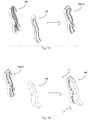
Figs. 3A and 3B schematically illustrate the assembling process of thelight module 200 shown inFig. 2 . - As shown in
Fig. 3A , thebracket 100 may first be assembled with the flexiblelight emitting strip 210, so that the flexiblelight emitting strip 210 may be received in thegroove 130 with theback surface 211a contacting theribs 111 on thebase plate 110. As described above, the flexiblelight emitting strip 210 may be a flexible LED light strip that comprises a plurality of LEDs. - Turning to
Fig. 3B , the assembly of thebracket 100 and the flexiblelight emitting strip 210 may be assembled with theoptical part 220 to form thelight module 200, in which the flexiblelight emitting strip 210 may be sandwiched between thebracket 100 and theoptical part 220, with thelight emitting surface 211b of the flexiblelight emitting strip 210 contacting thefirst surface 221a of theoptical part 220. Theribs 111 on thebase plate 100 can press theback surface 211a of the flexiblelight emitting strip 210, such that thelight emitting surface 211b of the flexiblelight emitting strip 210 contacts thefirst surface 221a of theoptical part 220 at any place of thelight emitting surface 211b. When thebracket 100, the flexiblelight emitting strip 210 and theoptical part 220 are assembled, each of thefirst engagement members 121 on thefirst side plate 120a of thebracket 100 and a corresponding one of thesecond engagement members 223 on thefirst side surface 222a of theoptical part 220 are coupled with each other and form a fastening structure such as a snap-fit structure shown inFig. 3B or a screwed fastening structure or the like; likewise, each of thefirst engagement members 121 on thesecond side plate 120b of thebracket 100 and a corresponding one of thesecond engagement members 223 on thesecond side surface 222b of theoptical part 220 are also coupled with each other and form a fastening structure. - As described above, the presence of projections on the
bracket 100, such as theribs 111 shown in the figures, changes the face-to-face contact between thebase plate 110 of thebracket 100 and theback surface 211a of the flexiblelight emitting strip 210 into a line-to-face contact. The face-to-face contact as well as the tape or glue way noted above may leave gaps between thebase plate 110 of thebracket 100 and theback surface 211a of the flexiblelight emitting strip 210, and thus may cause corresponding gaps between thelight emitting surface 211b of the flexiblelight emitting strip 210 and thefirst surface 221a of theoptical part 220, which may in turn affect the in-coupling of light from the flexiblelight emitting strip 210 into theoptical part 220. Compared to that, since theribs 111 in the present invention can be adjusted individually, e.g. the width and/or height of eachrib 111, the shape of the top end of eachrib 111 and the distribution of theribs 111 can be adjusted, the plurality ofribs 111 can eliminate any gap between thebase plate 110 and theback surface 211a of the flexiblelight emitting strip 210, which in turn ensures that no gap exists between thelight emitting surface 211b of the flexiblelight emitting strip 210 and thefirst surface 221a of theoptical part 220, improving the in-coupling of the light from the flexiblelight emitting strip 210 into theoptical part 220. - In further embodiments, there may be a plurality of recesses provided on the
back surface 211a of the flexiblelight emitting strip 210. Each recess on theback surface 211a may correspond to a rib on thebase plate 110 of thebracket 100, and may receive the corresponding rib when the flexiblelight emitting strip 210 is disposed in thegroove 130 of thebase plate 110. Accordingly, the recesses may have a shape and a distribution corresponding to those of theribs 111 on thebase plate 110. The recesses may further help to position the flexiblelight emitting strip 210 accurately with respect to thebracket 100. - Referring to
Fig. 4 , it depicts a section view of the assembledlight module 200 taken along line A-A inFig. 3B . As shown inFig. 4 , theribs 111 on thebase plate 110 of thebracket 100 abut theback surface 211a of the flexiblelight emitting strip 210, and thus press the flexiblelight emitting strip 210 onto thefirst surface 221a of theoptical part 220 tightly. Thus, as much light as possible from the flexiblelight emitting strip 210 can enter theoptical part 220. -
Fig. 5 is an enlarged schematic view of part B of the section view shown inFig. 4 . InFig. 5 , the projections are shown as ribs with arc shapes at their top ends, and the width W and the height H of a rib are also shown. Although the top end of each rib is shown to be in an arc shape in this figure, the ribs may have other shapes at the top ends, such as triangle shape. The contacting area between theback surface 211a of the flexiblelight emitting strip 210 and arib 111 is a line, so that the support at a certain local area can be improved by adjusting at least one of e.g. the height of one or more corresponding ribs, the top end shape of one or more corresponding ribs and the distribution of corresponding ribs. -
Fig. 6 schematically shows amethod 600 for manufacturing thebracket 100 of a light module in the form of a flowchart. It should be noted that the steps in the method described below are not necessarily executed in the order as listed. Instead, one or more of these steps may be executed in a different order or at the same time according to the actual situations. In addition, it can be easily appreciated that in themethod 600, any suitable materials, such as plastic materials, can be used for manufacturing thebracket 100. Themethod 600 comprises the following steps: -
step 610, manufacturing a sample bracket by injection moulding using injection molds; -
step 620, assembling the sample bracket with the flexiblelight emitting strip 210 and theoptical part 220; -
step 630, determining whether a gap exists between thelight emitting surface 211a of the flexiblelight emitting strip 210 and thefirst surface 221a of theoptical part 220; -
step 640, adjusting the injection molds based upon the position of the gap; and -
step 650, manufacturing a further sample bracket by injection moulding using the injection molds adjusted instep 640, wherein at least one of a width, a height and a distribution of the projections on a base plate of the further sample bracket is adjusted according to the position of the gap; - iterating the
steps 620 to 650 until no further gap between thelight emitting surface 211b of the flexiblelight emitting strip 210 and thefirst surface 221a of theoptical part 220 is determined anymore. Through the iteration, injection molds may finally be obtained which can be used to manufacture a bracket that perfectly, or within a desired tolerance, assemble the flexiblelight emitting strip 210 onto theoptical part 220 without any gaps in between. - In the
step 640 of themethod 600, adjusting the injection molds based upon the position of the gap may comprise adjusting the features on the moulding surface of a injection mold corresponding to the projections on the base plate of the bracket, such that at least one of a width, a height and a distribution of the projections on the base plate of the bracket can be adjusted accordingly during a subsequent injection moulding process. - In addition, in case that the
first side plate 120a and/or thesecond side plate 120b of thebracket 100 may compriseribs 111, thestep 630 of themethod 600 may accordingly comprise determining whether the gaps exist between thefirst side plate 120a and the flexiblelight emitting strip 210 and/or between thesecond side plate 120b and the flexiblelight emitting strip 210. - Variations to the disclosed embodiments can be understood and effected by the skilled person in practicing the claimed invention, from a study of the drawings, the disclosure, and the appended claims. The mere fact that certain measures are recited in mutually different dependent claims does not indicate that a combination of these measures cannot be used to advantage.
-
- 100
- bracket
- 110
- baseplate
- 110a
- first side edge
- 110b
- second side edge
- 111
- rib
- 120a
- first side plate
- 120b
- second side plate
- 121
- first engagement member
- 130
- groove
- 200
- light module
- 210
- flexible light emitting strip
- 211a
- back surface
- 211b
- light emitting surface
- 220
- optical part
- 221a
- first surface
- 221b
- second surface
- 222a
- first side surface
- 222b
- second side surface
- 223
- second engagement member
- 600
- manufacturing method
- 610, 620, 630, 640, 650
- steps of manufacturing method
Claims (15)
- A bracket (100) for assembling a flexible light emitting strip (210) in a light module (200), comprising:a base plate (110), comprising a first side edge (110a) and a second side edge (110b) opposite to each other;a first side plate (120a), located along the first side edge (110a), extending from the base plate (110) and comprising at least one first engagement member (121); anda second side plate (120b), located along the second side edge (110b), extending from the base plate (110), opposite to the first side plate (120a) and comprising at least one another first engagement member (121);wherein the base plate (110), the first side plate (120a) and the second side plate (120b) form a groove (130), andwherein the base plate (110) comprises a plurality of projections on a surface inside the groove (130).
- The bracket (100) according to claim 1, wherein the base plate (110), the first side plate (120a) and the second side plate (120b) are one-piece.
- The bracket (100) according to claim 1 or 2, wherein each of the first side edge (110a) and the second side edge (110b) has a curvilinear shape.
- The bracket (100) according to claim 1 or 2, wherein the first side edge (110a) and the second side edge (110b) are parallel to each other, and the first side plate (120a) and the second side plate (120b) are parallel to each other.
- The bracket (100) according to claim 1 or 2, wherein the projections on the base plate (110) are ribs (111) parallel to each other with each rib (111) extending from the first side edge (110a) or the second side edge (110b).
- The bracket (100) according to claim 5, wherein each of the first side plate (120a) and the second side plate (120b) comprise a plurality of projections on a surface inside the groove (130).
- The bracket (100) according to claim 6, wherein the projections on the first side plate (120a) are ribs (111) parallel to each other with each rib (111) extending from the first side edge (110a), and wherein the projections on the second side plate (120b) are ribs (111) parallel to each other with each rib (111) extending from the second side edge (110b).
- The bracket (100) according to claim 7, wherein each rib (111) has a width ranging from 0.1 mm to 1 mm.
- The bracket (100) according to claim 7, wherein each rib (111) has a height ranging from 0.2 mm to 1 mm.
- The bracket (100) according to claim 7, wherein each rib (111) has an arc shape on its top surface.
- The bracket (100) according to claim 7, wherein the ribs (111) on the base plate (110), the first side plate (120a) and the second side plate (120b) have a distribution ranging from 100 to 200 ribs (111) per meter along the first side edge (110a) or the second side edge (110b).
- A light module (200) comprising:the bracket (100) according to any one of claims 1 to 11;the flexible light emitting strip (210), comprising a back surface (211a) and a light emitting surface (211b) opposite to each other, wherein the back surface (211a) has a shape corresponding to the base plate (110); andan optical part (220), comprising a first surface (221a) and a second surface (221b) opposite to each other, a first side surface (222a) and a second side surface (222b) opposite to each other, wherein the first surface (221a) has a shape corresponding to the light emitting surface (211b) of the flexible light emitting strip (210), the first side surface (222a) of the optical part (220) having at least one second engagement member (223) corresponding to the at least one first engagement member (121) on the first side plate (120a) of the bracket (110), and the second side surface (222b) of the optical part (220) having at least one another second engagement member (223) corresponding to the at least one another first engagement member (121) on the second side plate (120b) of the bracket (100);wherein the flexible light emitting strip (210) is disposed in the groove (130) with the back surface (211a) of the flexible light emitting strip (210) contacting the projections on the base plate (110) of the bracket (100), the flexible light emitting strip (210) being sandwiched between the bracket (100) and the optical part (220) with the first surface (221a) of the optical part (220) contacting the light emitting surface (211b) of the flexible light emitting strip (210) and the projections on the base plate (110) pressing the back surface (211a) of the flexible light emitting strip (210), such that the light emitting surface (211b) of the flexible light emitting strip (210) contacts the first surface (221a) of the optical part (220) at any place of the light emitting surface (211b);wherein each of the first engagement members (121) and a corresponding one of the second engagement members (223) are coupled with each other; andwherein each of the another first engagement members (121) and a corresponding one of the another second engagement members (223) are coupled with each other.
- The light module (200) according to claim 12, wherein the flexible light emitting strip (210) is a flexible LED light strip.
- The light module (200) according to claim 12 or 13, wherein a plurality of recesses are provided on the back surface (211a) of the flexible light emitting strip (210) with each recess on the back surface corresponding to one of the projections on the base plate (110).
- A method (600) for manufacturing the bracket (100) of the light module (200) according to claim 12, comprising the steps of:manufacturing a sample bracket by injection moulding using injection molds;assembling the sample bracket with the flexible light emitting strip (210) and the optical part (220);determining a gap between the light emitting surface (211b) of the flexible light emitting strip (210) and the first surface (221a) of the optical part (220);adjusting the injection molds based upon the position of the gap;manufacturing a further sample bracket by injection moulding using the injection molds adjusted in the previous step, wherein at least one of a width, a height and a distribution of the projections on the base plate of the further sample bracket is adjusted according to the position of the gap; anditerating the steps of assembling, gap determination, injection molds adjustment, and sample bracket manufacturing until no further gap between the light emitting surface (211b) of the flexible light emitting strip (210) and the first surface (221a) of the optical part (220) is determined anymore.
Priority Applications (1)
| Application Number | Priority Date | Filing Date | Title |
|---|---|---|---|
| EP20172376.4A EP3904753B1 (en) | 2020-04-30 | 2020-04-30 | Bracket, light module including the same and method for manufacturing the same |
Applications Claiming Priority (1)
| Application Number | Priority Date | Filing Date | Title |
|---|---|---|---|
| EP20172376.4A EP3904753B1 (en) | 2020-04-30 | 2020-04-30 | Bracket, light module including the same and method for manufacturing the same |
Publications (2)
| Publication Number | Publication Date |
|---|---|
| EP3904753A1 true EP3904753A1 (en) | 2021-11-03 |
| EP3904753B1 EP3904753B1 (en) | 2025-11-12 |
Family
ID=70482363
Family Applications (1)
| Application Number | Title | Priority Date | Filing Date |
|---|---|---|---|
| EP20172376.4A Active EP3904753B1 (en) | 2020-04-30 | 2020-04-30 | Bracket, light module including the same and method for manufacturing the same |
Country Status (1)
| Country | Link |
|---|---|
| EP (1) | EP3904753B1 (en) |
Citations (5)
| Publication number | Priority date | Publication date | Assignee | Title |
|---|---|---|---|---|
| KR20100084093A (en) * | 2009-01-15 | 2010-07-23 | 최중영 | Light emitting apparatus |
| EP3072747A2 (en) * | 2015-03-26 | 2016-09-28 | Sumitomo Wiring Systems, Ltd. | Protector, assembly of wiring module with protector and assembling method therefor |
| EP3348897A1 (en) * | 2017-01-12 | 2018-07-18 | OSRAM GmbH | A lighting system, corresponding components, kit and method |
| US20180209599A1 (en) * | 2014-07-31 | 2018-07-26 | Valerica Grigore | Elongated l.e.d. lighting systems, manufacturing and methods to configure the same |
| US20200109828A1 (en) * | 2018-10-03 | 2020-04-09 | Vista Manufacturing Inc. | Flexible light assembly |
Family Cites Families (3)
| Publication number | Priority date | Publication date | Assignee | Title |
|---|---|---|---|---|
| DE2330494C2 (en) * | 1973-06-15 | 1982-06-16 | Adam Opel AG, 6090 Rüsselsheim | Bumpers for automobiles |
| US6866313B2 (en) * | 2002-07-30 | 2005-03-15 | General Electric Co. | Bumper assembly including and energy absorber |
| DE112008000265T5 (en) * | 2007-02-02 | 2010-01-14 | Netshape Energy Management LLC, Novi | Energy absorber with crush boxes and rear straps |
-
2020
- 2020-04-30 EP EP20172376.4A patent/EP3904753B1/en active Active
Patent Citations (5)
| Publication number | Priority date | Publication date | Assignee | Title |
|---|---|---|---|---|
| KR20100084093A (en) * | 2009-01-15 | 2010-07-23 | 최중영 | Light emitting apparatus |
| US20180209599A1 (en) * | 2014-07-31 | 2018-07-26 | Valerica Grigore | Elongated l.e.d. lighting systems, manufacturing and methods to configure the same |
| EP3072747A2 (en) * | 2015-03-26 | 2016-09-28 | Sumitomo Wiring Systems, Ltd. | Protector, assembly of wiring module with protector and assembling method therefor |
| EP3348897A1 (en) * | 2017-01-12 | 2018-07-18 | OSRAM GmbH | A lighting system, corresponding components, kit and method |
| US20200109828A1 (en) * | 2018-10-03 | 2020-04-09 | Vista Manufacturing Inc. | Flexible light assembly |
Also Published As
| Publication number | Publication date |
|---|---|
| EP3904753B1 (en) | 2025-11-12 |
Similar Documents
| Publication | Publication Date | Title |
|---|---|---|
| US10197242B2 (en) | Lens arrays and mountings | |
| US9039251B2 (en) | Light fixtures and multi-plane light modifying elements | |
| US9989204B2 (en) | Substrate tensioning systems | |
| US8608351B2 (en) | Removable optical component for luminaire | |
| US20100284195A1 (en) | Led lamp | |
| EP2495490B1 (en) | Led lighting device which has stable structure and is easily assembled and disassembled | |
| CN105674066B (en) | Low profile extruded profile | |
| US9651733B2 (en) | Back plate and method for manufacturing the same and backlight module | |
| US8876337B2 (en) | Light fixtures and multi-plane light modifying elements | |
| US20090154157A1 (en) | Light emitting unit and optical film assembly thereof | |
| US20120069568A1 (en) | Lighting module and corresponding method | |
| CN110671680A (en) | Strip-shaped illuminating lamp | |
| US8388181B2 (en) | Light source assembly using light emitting diodes and reflective sheet set | |
| CN202902025U (en) | Backlight module | |
| JP2018010264A (en) | Display device | |
| EP3904753B1 (en) | Bracket, light module including the same and method for manufacturing the same | |
| JP2019197637A (en) | Lighting fixture | |
| CN109764286A (en) | A direct type luminous panel light | |
| JP5584723B2 (en) | Surface light source device and display device using surface light source device | |
| WO2013065534A1 (en) | Illumination device, backlight, and liquid crystal display device | |
| CN217714658U (en) | Lamp assembly and lighting lamp with same | |
| US20170293071A1 (en) | Planar lighting device | |
| US6238064B1 (en) | Decorative lighting louver element | |
| WO2019154930A1 (en) | A planar led light source module | |
| KR20240000043U (en) | Direct type panel lamp with flat appearance |
Legal Events
| Date | Code | Title | Description |
|---|---|---|---|
| PUAI | Public reference made under article 153(3) epc to a published international application that has entered the european phase |
Free format text: ORIGINAL CODE: 0009012 |
|
| STAA | Information on the status of an ep patent application or granted ep patent |
Free format text: STATUS: THE APPLICATION HAS BEEN PUBLISHED |
|
| AK | Designated contracting states |
Kind code of ref document: A1 Designated state(s): AL AT BE BG CH CY CZ DE DK EE ES FI FR GB GR HR HU IE IS IT LI LT LU LV MC MK MT NL NO PL PT RO RS SE SI SK SM TR |
|
| B565 | Issuance of search results under rule 164(2) epc |
Effective date: 20201001 |
|
| STAA | Information on the status of an ep patent application or granted ep patent |
Free format text: STATUS: REQUEST FOR EXAMINATION WAS MADE |
|
| 17P | Request for examination filed |
Effective date: 20220502 |
|
| RBV | Designated contracting states (corrected) |
Designated state(s): AL AT BE BG CH CY CZ DE DK EE ES FI FR GB GR HR HU IE IS IT LI LT LU LV MC MK MT NL NO PL PT RO RS SE SI SK SM TR |
|
| STAA | Information on the status of an ep patent application or granted ep patent |
Free format text: STATUS: EXAMINATION IS IN PROGRESS |
|
| 17Q | First examination report despatched |
Effective date: 20230726 |
|
| GRAP | Despatch of communication of intention to grant a patent |
Free format text: ORIGINAL CODE: EPIDOSNIGR1 |
|
| STAA | Information on the status of an ep patent application or granted ep patent |
Free format text: STATUS: GRANT OF PATENT IS INTENDED |
|
| RIC1 | Information provided on ipc code assigned before grant |
Ipc: F21S 4/22 20160101AFI20250715BHEP Ipc: F21V 15/01 20060101ALI20250715BHEP Ipc: F21Y 107/70 20160101ALN20250715BHEP Ipc: F21Y 115/10 20160101ALN20250715BHEP |
|
| INTG | Intention to grant announced |
Effective date: 20250728 |
|
| GRAS | Grant fee paid |
Free format text: ORIGINAL CODE: EPIDOSNIGR3 |
|
| GRAA | (expected) grant |
Free format text: ORIGINAL CODE: 0009210 |
|
| STAA | Information on the status of an ep patent application or granted ep patent |
Free format text: STATUS: THE PATENT HAS BEEN GRANTED |
|
| AK | Designated contracting states |
Kind code of ref document: B1 Designated state(s): AL AT BE BG CH CY CZ DE DK EE ES FI FR GB GR HR HU IE IS IT LI LT LU LV MC MK MT NL NO PL PT RO RS SE SI SK SM TR |
|
| REG | Reference to a national code |
Ref country code: CH Ref legal event code: F10 Free format text: ST27 STATUS EVENT CODE: U-0-0-F10-F00 (AS PROVIDED BY THE NATIONAL OFFICE) Effective date: 20251112 Ref country code: GB Ref legal event code: FG4D |
|
| P01 | Opt-out of the competence of the unified patent court (upc) registered |
Free format text: CASE NUMBER: UPC_APP_0011402_3904753/2025 Effective date: 20251029 |
|
| REG | Reference to a national code |
Ref country code: IE Ref legal event code: FG4D |
|
| REG | Reference to a national code |
Ref country code: DE Ref legal event code: R096 Ref document number: 602020062007 Country of ref document: DE |
|
| REG | Reference to a national code |
Ref country code: NL Ref legal event code: MP Effective date: 20251112 |
|
| PGFP | Annual fee paid to national office [announced via postgrant information from national office to epo] |
Ref country code: GB Payment date: 20260309 Year of fee payment: 7 |
|
| PG25 | Lapsed in a contracting state [announced via postgrant information from national office to epo] |
Ref country code: ES Free format text: LAPSE BECAUSE OF FAILURE TO SUBMIT A TRANSLATION OF THE DESCRIPTION OR TO PAY THE FEE WITHIN THE PRESCRIBED TIME-LIMIT Effective date: 20251112 |
|
| REG | Reference to a national code |
Ref country code: LT Ref legal event code: MG9D |
|
| PG25 | Lapsed in a contracting state [announced via postgrant information from national office to epo] |
Ref country code: NO Free format text: LAPSE BECAUSE OF FAILURE TO SUBMIT A TRANSLATION OF THE DESCRIPTION OR TO PAY THE FEE WITHIN THE PRESCRIBED TIME-LIMIT Effective date: 20260212 |
|
| PG25 | Lapsed in a contracting state [announced via postgrant information from national office to epo] |
Ref country code: FI Free format text: LAPSE BECAUSE OF FAILURE TO SUBMIT A TRANSLATION OF THE DESCRIPTION OR TO PAY THE FEE WITHIN THE PRESCRIBED TIME-LIMIT Effective date: 20251112 Ref country code: HR Free format text: LAPSE BECAUSE OF FAILURE TO SUBMIT A TRANSLATION OF THE DESCRIPTION OR TO PAY THE FEE WITHIN THE PRESCRIBED TIME-LIMIT Effective date: 20251112 Ref country code: AT Free format text: LAPSE BECAUSE OF FAILURE TO SUBMIT A TRANSLATION OF THE DESCRIPTION OR TO PAY THE FEE WITHIN THE PRESCRIBED TIME-LIMIT Effective date: 20251112 |
|
| REG | Reference to a national code |
Ref country code: AT Ref legal event code: MK05 Ref document number: 1856995 Country of ref document: AT Kind code of ref document: T Effective date: 20251112 |
|
| PG25 | Lapsed in a contracting state [announced via postgrant information from national office to epo] |
Ref country code: NL Free format text: LAPSE BECAUSE OF FAILURE TO SUBMIT A TRANSLATION OF THE DESCRIPTION OR TO PAY THE FEE WITHIN THE PRESCRIBED TIME-LIMIT Effective date: 20251112 |
|
| PG25 | Lapsed in a contracting state [announced via postgrant information from national office to epo] |
Ref country code: RS Free format text: LAPSE BECAUSE OF FAILURE TO SUBMIT A TRANSLATION OF THE DESCRIPTION OR TO PAY THE FEE WITHIN THE PRESCRIBED TIME-LIMIT Effective date: 20260212 |
|
| PG25 | Lapsed in a contracting state [announced via postgrant information from national office to epo] |
Ref country code: IS Free format text: LAPSE BECAUSE OF FAILURE TO SUBMIT A TRANSLATION OF THE DESCRIPTION OR TO PAY THE FEE WITHIN THE PRESCRIBED TIME-LIMIT Effective date: 20260312 |
|
| PG25 | Lapsed in a contracting state [announced via postgrant information from national office to epo] |
Ref country code: PT Free format text: LAPSE BECAUSE OF FAILURE TO SUBMIT A TRANSLATION OF THE DESCRIPTION OR TO PAY THE FEE WITHIN THE PRESCRIBED TIME-LIMIT Effective date: 20260312 |
|
| PG25 | Lapsed in a contracting state [announced via postgrant information from national office to epo] |
Ref country code: PL Free format text: LAPSE BECAUSE OF FAILURE TO SUBMIT A TRANSLATION OF THE DESCRIPTION OR TO PAY THE FEE WITHIN THE PRESCRIBED TIME-LIMIT Effective date: 20251112 |
|
| PG25 | Lapsed in a contracting state [announced via postgrant information from national office to epo] |
Ref country code: LV Free format text: LAPSE BECAUSE OF FAILURE TO SUBMIT A TRANSLATION OF THE DESCRIPTION OR TO PAY THE FEE WITHIN THE PRESCRIBED TIME-LIMIT Effective date: 20251112 |
|
| PG25 | Lapsed in a contracting state [announced via postgrant information from national office to epo] |
Ref country code: BG Free format text: LAPSE BECAUSE OF FAILURE TO SUBMIT A TRANSLATION OF THE DESCRIPTION OR TO PAY THE FEE WITHIN THE PRESCRIBED TIME-LIMIT Effective date: 20251112 |