EP3904745A1 - Steel-pipe threaded joint - Google Patents
Steel-pipe threaded joint Download PDFInfo
- Publication number
- EP3904745A1 EP3904745A1 EP19903256.6A EP19903256A EP3904745A1 EP 3904745 A1 EP3904745 A1 EP 3904745A1 EP 19903256 A EP19903256 A EP 19903256A EP 3904745 A1 EP3904745 A1 EP 3904745A1
- Authority
- EP
- European Patent Office
- Prior art keywords
- pin
- box
- thread
- perfect
- sealing surface
- Prior art date
- Legal status (The legal status is an assumption and is not a legal conclusion. Google has not performed a legal analysis and makes no representation as to the accuracy of the status listed.)
- Granted
Links
Images


Classifications
-
- F—MECHANICAL ENGINEERING; LIGHTING; HEATING; WEAPONS; BLASTING
- F16—ENGINEERING ELEMENTS AND UNITS; GENERAL MEASURES FOR PRODUCING AND MAINTAINING EFFECTIVE FUNCTIONING OF MACHINES OR INSTALLATIONS; THERMAL INSULATION IN GENERAL
- F16L—PIPES; JOINTS OR FITTINGS FOR PIPES; SUPPORTS FOR PIPES, CABLES OR PROTECTIVE TUBING; MEANS FOR THERMAL INSULATION IN GENERAL
- F16L15/00—Screw-threaded joints; Forms of screw-threads for such joints
- F16L15/001—Screw-threaded joints; Forms of screw-threads for such joints with conical threads
- F16L15/002—Screw-threaded joints; Forms of screw-threads for such joints with conical threads with more than one threaded section
-
- E—FIXED CONSTRUCTIONS
- E21—EARTH OR ROCK DRILLING; MINING
- E21B—EARTH OR ROCK DRILLING; OBTAINING OIL, GAS, WATER, SOLUBLE OR MELTABLE MATERIALS OR A SLURRY OF MINERALS FROM WELLS
- E21B17/00—Drilling rods or pipes; Flexible drill strings; Kellies; Drill collars; Sucker rods; Cables; Casings; Tubings
- E21B17/02—Couplings; joints
- E21B17/04—Couplings; joints between rod or the like and bit or between rod and rod or the like
- E21B17/042—Threaded
- E21B17/0423—Threaded with plural threaded sections, e.g. with two-step threads
-
- F—MECHANICAL ENGINEERING; LIGHTING; HEATING; WEAPONS; BLASTING
- F16—ENGINEERING ELEMENTS AND UNITS; GENERAL MEASURES FOR PRODUCING AND MAINTAINING EFFECTIVE FUNCTIONING OF MACHINES OR INSTALLATIONS; THERMAL INSULATION IN GENERAL
- F16L—PIPES; JOINTS OR FITTINGS FOR PIPES; SUPPORTS FOR PIPES, CABLES OR PROTECTIVE TUBING; MEANS FOR THERMAL INSULATION IN GENERAL
- F16L15/00—Screw-threaded joints; Forms of screw-threads for such joints
- F16L15/04—Screw-threaded joints; Forms of screw-threads for such joints with additional sealings
Definitions
- the present disclosure relates to a threaded connection used to connect steel pipes.
- oil-well pipes such as casing or tubing are used to mine underground resources.
- An oil-well pipe is composed of a series of steel pipes connected together, where a threaded connection is used to connect such pipes.
- a coupling-type connection connects a pair of pipes, one of which is a steel pipe and the other one is a coupling.
- a male thread is provided on the outer periphery of each of the ends of the steel pipe, while a female thread is provided on the inner periphery of each of the ends of the coupling. Then, a male thread of a steel pipe is screwed into a female thread of the coupling such that they are made up and connected.
- An integral connection connects a pair of pipes that are both steel pipes, and does not use a separate coupling.
- a male thread is provided on the outer periphery of one end of each steel pipe, while a female thread is provided on the inner periphery of the other end. Then, the male thread of one steel pipe is screwed into the female thread of another steel pipe such that they are made up and connected.
- a connection portion of a pipe end on which a male thread is provided includes an element to be inserted into a female thread, and thus is usually referred to as pin.
- a connection portion of a pipe end on which a female thread is provided includes an element for receiving a male thread, and thus is referred to as box.
- a pin and a box constitute ends of pipes and thus are tubular in shape.
- a threaded connection for oil-well pipe exhibits high sealability at its seal.
- the sealing portion of the pin has a larger diameter than the diameter of the sealing portion of the box.
- these sealing portions closely contact each other in a fitting manner to achieve an interference fit, thereby forming a seal using metal-to-metal contact.
- the difference between the diameter of the sealing portion of the pin and the diameter of the sealing portion of the box is referred to as "seal interference".
- the larger the seal interference the higher the seal contact force, providing better sealability.
- Patent Document 1 discloses a threaded connection for steel pipe that improves sealability against internal and external pressures (see paragraph [0020]).
- This threaded connection includes, starting from the tip of the pin (i.e., from the pipe end of the body of the oil-well pipe): shoulder surfaces, first sealing surfaces, first male/female threads, auxiliary shoulder surfaces, annular portions, second sealing surfaces, and second male/female threads (see paragraph [0063] and FIG. 6 ).
- the first male thread will be hereinafter referred to as “inner male thread”, the first female thread as “inner female thread”, the second male thread as “outer male thread”, the second female thread as “outer female thread”, the inner male and female threads collectively as “inner threads”, the outer male and female threads collectively as “outer threads”, and the threaded connection including inner and outer threads as "two-step threaded connection”.
- Patent Document 2 JP Hei10(1998)-89554 A discloses a slim-type threaded connection for oil-well pipe where only the torque shoulders have high strength and that provides good compression resistance and corrosion resistance (see paragraph [0016]).
- This threaded connection is an integral threaded connection for oil-well pipe including threads that enable threadably tightening the pin and box, a seal for providing sufficient sealability against internal or external pressures or against both kinds of pressures on the oil-well pipe, and torque shoulders that enable controlling make-up torque, where the strength of the torque shoulders is higher than those of the other portions of the connection and the body of the oil-well pipe (see paragraph [0018] and FIG. 1 ).
- This connection too, is a "two-step threaded connection”.
- Patent Document 3 discloses a threaded connection for steel pipe that provides good sealability and also prevents crevice corrosion (see paragraph [0017]). This document specifies such an interference ⁇ shld between the intermediate shoulders that the inner shoulders contact each other at the same time as the intermediate shoulders contact each other (see paragraphs [0050] to [0057] and FIG. 3 ). This connection, too, is a "two-step threaded connection”.
- the inventors newly found that, upon initiation of the make-up of a two-step threaded connection, galling can easily occur on either the inner or outer threads.
- An object of the present disclosure is to provide a threaded connection for steel pipe in which galling does not easily occur on any of the inner and outer threads.
- the inventors analyzed galling that occurs on either the inner threads or outer threads upon initiation of the make-up of a two-step threaded connection to determine the reasons, and obtained the following new findings:
- the inner threads contact each other before the outer threads contact each other, or the outer threads contact each other before the inner threads contact each other.
- the threads are not in complete engagement, which means that make-up proceeds while the axes of the pin and box are not completely aligned, i.e., in a state called misalignment.
- the inner threads receive excessive loads
- the outer threads receive excessive loads.
- the inner or outer threads that receive excessive loads experience locally high surface pressures such that galling can easily occur.
- a threaded connection for steel pipe includes: a tubular pin; and a tubular box, the pin being screwed into the box such that the pin and the box are made up.
- the pin includes: a tapered inner male thread; a tapered outer male thread; and a pin intermediate shoulder surface.
- the inner male thread is provided on an outer periphery of the pin and located relatively close to a tip of the pin.
- the outer male thread is provided on the outer periphery of the pin and located relatively close to an end of the pin opposite to the tip.
- the pin intermediate shoulder surface is located between the inner male thread and the outer male thread.
- the box includes: a tapered inner female thread; a tapered outer female thread; and a box intermediate shoulder surface.
- the inner female thread is provided on an inner periphery of the box to correspond to the inner male thread.
- the outer female thread is provided on the inner periphery of the box to correspond to the outer male thread.
- the box intermediate shoulder surface faces the pin intermediate shoulder surface, the box intermediate shoulder surface being in contact with the pin intermediate shoulder surface when the pin and the box are made up.
- Each of the inner male thread, the outer male thread, the inner female thread and the outer female thread includes a perfect thread portion, and each of the perfect thread portions includes an inner end located relatively close to the tip of the pin and an outer end located relatively close to the end of the pin opposite to the tip.
- the pin and the box when made up, have a longitudinal cross section containing an axis of the steel pipe.
- An orthogonal coordinate system introduced in the longitudinal cross section has an x-axis represented by the axis of the steel pipe, a y-axis represented by a radius of the steel pipe, and an origin (0,0) represented by an intersection of a plane containing the pin intermediate shoulder surface and the box intermediate shoulder surface, on one hand, and the axis of the steel pipe, on the other hand.
- (x 1 ,y 1 ) indicates coordinates of the inner end of the perfect thread portion of the inner male thread.
- (x 2 ,y 2 ) indicates coordinates of the outer end of the perfect thread portion of the inner male thread.
- (u 1 ,v 1 ) indicates coordinates of the inner end of the perfect thread portion of the outer male thread.
- (u 2 ,v 2 ) indicates coordinates of the outer end of the perfect thread portion of the outer male thread.
- (X 1 ,Y 1 ) indicates coordinates of the inner end of the perfect thread portion of the inner female thread.
- (X 2 ,Y 2 ) indicates coordinates of the outer end of the perfect thread portion of the inner female thread.
- (U 1 ,V 1 ) indicates coordinates of the inner end of the perfect thread portion of the outer female thread.
- (U 2 ,V 2 ) indicates coordinates of the outer end of the perfect thread portion of the outer female thread.
- the inner threads contact each other substantially at the same time as the outer threads contact each other, thereby preventing galling on the inner and outer threads.
- the threaded connection for steel pipe includes: a tubular pin; and a tubular box, the pin being screwed into the box such that the pin and the box are made up.
- the pin includes: a tapered inner male thread; a tapered outer male thread; and a pin intermediate shoulder surface.
- the inner male thread is provided on an outer periphery of the pin and located relatively close to a tip of the pin.
- the outer male thread is provided on the outer periphery of the pin and located relatively close to an end of the pin opposite to the tip.
- the pin intermediate shoulder surface is located between the inner male thread and the outer male thread.
- the box includes: a tapered inner female thread; a tapered outer female thread; and a box intermediate shoulder surface.
- the inner female thread is provided on an inner periphery of the box to correspond to the inner male thread.
- the outer female thread is provided on the inner periphery of the box to correspond to the outer male thread.
- the box intermediate shoulder surface faces the pin intermediate shoulder surface, the box intermediate shoulder surface being in contact with the pin intermediate shoulder surface when the pin and the box are made up.
- Each of the inner male thread, the outer male thread, the inner female thread and the outer female thread includes a perfect thread portion, and each of the perfect thread portions includes an inner end located relatively close to the tip of the pin and an outer end located relatively close to the end of the pin opposite to the tip.
- the pin and the box when made up, have a longitudinal cross section containing an axis of the steel pipe.
- An orthogonal coordinate system introduced in the longitudinal cross section has an x-axis represented by the axis of the steel pipe, a y-axis represented by a radius of the steel pipe, and an origin (0,0) represented by an intersection of a plane containing the pin intermediate shoulder surface and the box intermediate shoulder surface, on one hand, and the axis of the steel pipe, on the other hand.
- (x 1 ,y 1 ) indicates coordinates of the inner end of the perfect thread portion of the inner male thread.
- (x 2 ,y 2 ) indicates coordinates of the outer end of the perfect thread portion of the inner male thread.
- (u 1 ,v 1 ) indicates coordinates of the inner end of the perfect thread portion of the outer male thread.
- (u 2 ,v 2 ) indicates coordinates of the outer end of the perfect thread portion of the outer male thread.
- (X 1 ,Y 1 ) indicates coordinates of the inner end of the perfect thread portion of the inner female thread.
- (X 2 ,Y 2 ) indicates coordinates of the outer end of the perfect thread portion of the inner female thread.
- (U 1 ,V 1 ) indicates coordinates of the inner end of the perfect thread portion of the outer female thread.
- (U 2 ,V 2 ) indicates coordinates of the outer end of the perfect thread portion of the outer female thread.
- the inner threads contact each other substantially at the same time as the outer threads contact each other, thereby preventing galling on the inner and outer threads.
- the pin may further include: a nose provided at the tip of the pin; a pin inner sealing surface located between the nose and the inner male thread; and a pin intermediate sealing surface provided between the outer male thread and the pin intermediate shoulder surface.
- the box may further include: a box inner sealing surface facing the pin inner sealing surface, the box inner sealing surface being in contact with the pin inner sealing surface when the pin and the box are made up; and a box intermediate sealing surface facing the pin intermediate sealing surface, the box intermediate sealing surface being in contact with the pin intermediate sealing surface when the pin and the box are made up.
- the pin intermediate sealing surface may have a smaller diameter than an envelope line of a crest of the outer female thread.
- Arrangement 3 prevents the outer female thread and pin intermediate sealing surface from contacting each other.
- the threaded connection may further satisfy the following expressions, Expressions (3) and (4): X 2 ⁇ x 1 + L 1 ⁇ 5 mm and U 2 ⁇ u 1 + L 2 ⁇ 5 mm
- the inner threads may contact each other along 5 mm or more, and the outer threads may contact each other along 5 mm or more.
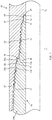
- a threaded connection for steel pipe is a coupling-type threaded connection that includes a tubular pin 10 and a tubular box 20 to be made up on the pin 10 when the pin 10 is screwed in.
- the pin 10 includes a nose 12, a tapered inner male thread 14, a tapered outer male thread 17, a pin inner sealing surface 13, a pin intermediate shoulder surface 18, a pin intermediate sealing surface 16, and a pin annular portion 15a.
- the nose 12 is provided at the tip of the pin 10.
- the inner male thread 14 is provided on the outer periphery of the pin 10 and located relatively close to the tip of the pin 10.
- the outer male thread 17 is provided on the outer periphery of the pin 10 and located relatively close to the end of the pin 10 opposite to the tip.
- the pin inner sealing surface 13 is located between the nose 12 and inner male thread 14.
- the pin intermediate shoulder surface 18 is located between the inner and outer male threads 14 and 17.
- the pin intermediate sealing surface 16 is located between the outer male thread 17 and pin intermediate shoulder surface 18.
- the pin annular portion 15a is located between the pin intermediate shoulder surface 18 and pin intermediate sealing surface 16.
- the box 20 includes a recess 22, a tapered inner female thread 24, a tapered outer female thread 27, a box inner sealing surface 23, a box intermediate shoulder surface 28, a box intermediate sealing surface 26, and a box annular portion 25a.
- the recess 22 corresponds to the nose 12.
- the inner female thread 24 is provided on the inner periphery of the box 20 to correspond to the inner male thread 14.
- the outer female thread 27 is provided on the inner periphery of the box 20 to correspond to the outer male thread 17.
- the box inner sealing surface 23 faces the pin inner sealing surface 13, and is in contact with the pin inner sealing surface 13 when the pin 10 and box 20 are made up.
- the box intermediate shoulder surface 28 faces the pin intermediate shoulder surface 18, and is in contact with the pin intermediate shoulder surface 18 when the pin 10 and box 20 are made up.
- the box intermediate sealing surface 26 faces the pin intermediate sealing surface 16, and is in contact with the pin intermediate sealing surface 16 when the pin 10 and box 20 are made up.
- the box annular portion 25a faces the pin annular portion 15a, and is spaced apart from the pin annular portion 15a when the pin 10 and box 20 are made up.
- the inner male and female threads 14 and 24 will be hereinafter sometimes collectively referred to as “inner threads 14 and 24".
- the outer male and female threads 17 and 27 will be sometimes collectively referred to as “outer threads 17 and 27".
- This threaded connection 1 is a two-step threaded connection including the inner threads 14 and 24 and the outer threads 17 and 27.
- Each of the pin inner sealing surface 13 and pin intermediate sealing surface 16 has the shape of a face equivalent to the periphery of a truncated cone decreasing in diameter toward the tip, or the shape obtained by combining the periphery of such a truncated cone and a face equivalent to the periphery of a solid of revolution obtained by rotating a curve, such as an arc, about the axis of the steel pipe (hereinafter sometimes simply referred to as "pipe axis").
- the nose 12 is tubular in shape and adjacent to the pin inner sealing surface 13 in the direction of the pipe axis CL.
- the outer peripheral surface of the nose 12 may be a taper surface with the same slope as the taper of the pin inner sealing surface 13, or with a smaller (i.e., gentler) or lager (i.e., steeper) slope.
- this outer peripheral surface of the nose 12 is a taper surface
- this outer peripheral surface has the shape of a face equivalent to the periphery of a truncated cone decreasing in diameter toward the tip, or the shape obtained by combining the periphery of such a truncated cone and a face equivalent to the periphery of a solid of revolution obtained by rotating a curve, such as an arc, about the pipe axis CL.
- the pin 10 further includes a pin auxiliary shoulder surface 11 provided at the tip of the pin 10.
- the box 20 further includes a box auxiliary shoulder surface 21 adapted to face the pin auxiliary shoulder surface 11.
- the pin auxiliary shoulder surface 11 may or may not be in contact with the box auxiliary shoulder surface 21 when the pin 10 and box 20 are made up.
- the pin auxiliary shoulder surface 11 is an annular surface generally perpendicular to the pipe axis CL. More exactly, the auxiliary shoulder surface 11 is slightly inclined such that its outer periphery is located further toward the tip of the pin 10.
- the intermediate shoulder surface 18 is located between the inner male thread 14 and pin annular portion 15a.
- the intermediate shoulder surface 18 is adjacent to the pin annular portion 15a.
- the intermediate shoulder surface 18 is an annular surface perpendicular to the pipe axis CL.
- the intermediate shoulder surface 18 may be slightly inclined such that its outer periphery is located further toward the tip of the pin 10.
- the pin annular portion 15a is adjacent to forward of the pin intermediate sealing surface 16 in the direction of the pipe axis CL.
- the inner male thread 14 is adjacent to the pin annular portion 15a.
- the pin annular portion 15b is adjacent to rearward of the pin intermediate sealing surface 16 in the direction of the pipe axis CL.
- the outer male thread 17 is adjacent to the pin annular portion 15b.
- the outer peripheral surface of the pin annular portion 15a may have any shape that can ensure stiffness, and may be a cylindrical surface or a taper surface with a smaller (or gentler) slope than the thread taper of the inner male thread 14, or a curved surface. The same applies to the outer peripheral surface of the pin annular portion 15b.
- the box inner sealing surface 23 protrudes toward the pin inner sealing surface 13.
- the box inner sealing surface 23 may not protrude.
- the pin inner sealing surface 13 protrudes toward the box inner sealing surface 23.
- the inner male and female threads 14 and 24 are tapered threads that can engage each other, and are trapezoidal threads.
- the outer male and female threads 17 and 27 are tapered threads that can engage each other, and are trapezoidal threads.
- the taper surfaces of the inner threads 14 and 24 are located closer to the pipe axis CL than the taper surfaces of the outer threads 17 and 27 are. This is because the intermediate shoulder surfaces 18 and 28 are provided between the inner threads 14 and 24, on one hand, and the outer threads 17 and 27, on the other hand.
- the portions of the pin 10 associated with the inner male thread 14 and pin inner sealing surface 13 have relatively small outer diameters and thus have relatively small wall thicknesses.
- the portions of the pin 10 associated with the pin inner sealing surface 16 and outer male thread 17 have relatively large outer diameters and thus have relatively large wall thicknesses.
- the inner male and female threads 14 and 24 allow each other to be screwed in, and, when the connection is made up, closely contact each other in a fitting manner to achieve an interference fit.
- the outer male and female threads 17 and 27 achieve an interference fit.
- the inner sealing surfaces 13 and 23 contact each other and the intermediate sealing surfaces 16 and 26 contact each other and, when the connection is made up, each pair comes into close contact in a fitting manner to achieve an interference fit.
- the inner sealing surfaces 13 and 23 and the intermediate sealing surfaces 16 and 26 form an inner seal and an intermediate seal, respectively, using metal-to-metal contact.
- a clearance is formed between the nose 12 of the pin 10 and the recess 22 of the box 20.
- a clearance is also formed between the pin and box annular portions 15a and 25a.
- a clearance is also formed between the pin and box annular portions 15b and 25b.
- the intermediate shoulder surfaces 18 and 28 are in contact with each other when the connection is made up. When the intermediate shoulder surfaces 18 and 28 are in press contact a tightening axial force is applied, mainly to the load flank of the outer male thread 17.
- the inner male thread 14 includes a perfect thread portion (hereinafter referred to as "pin inner perfect thread portion") 141.
- the outer male thread 17 includes a perfect thread portion (hereinafter referred to as “pin outer perfect thread portion") 171.
- the inner female thread 24 includes a perfect thread portion (hereinafter referred to as “box inner perfect thread portion”) 241.
- the outer female thread 27 includes a perfect thread portion (hereinafter referred to as box outer perfect thread portion”) 271.
- the pin inner perfect thread portion 141 includes an inner end 141i located relatively close to the tip of the pin 10 and an outer end 141o located relatively close to the end of the pin 10 opposite to its tip.
- the pin outer perfect thread portion 171 includes an inner end 171i located relatively close to the tip of the pin 10 and an outer end 171o located relatively close to the end of the pin 10 opposite to its tip.
- the box inner perfect thread portion 241 includes an inner end 241i located relatively close to the tip of the pin 10 (i.e., relatively close to the end of the box 20 opposite to its tip) and an outer end 241o located relatively close to the end of the pin 10 opposite to its tip (i.e., relatively close to the tip of the box 20).
- the box outer perfect thread portion 271 includes an inner end 271i located relatively close to the tip of the pin 10 (i.e., relatively close to the end of the box 20 opposite to its tip) and an outer end 271o located relatively close to the end of the pin 10 opposite to its tip (i.e., relatively close to the tip of the box 20).
- the inner male thread 14 further includes a bevel (hereinafter referred to as "pin inner bevel”) 142.
- the outer male thread 17 further includes an imperfect thread portion (hereinafter referred to as “pin outer imperfect thread portion”) 172 and a bevel (hereinafter referred to as “pin outer bevel”) 173.
- the inner female thread 24 further includes bevels (hereinafter referred to as “box inner bevels”) 242 and 243.
- the outer female thread 27 includes an imperfect thread portion (hereinafter referred to as box outer imperfect thread portion”) 272.
- both the crest (i.e., thread ridge) and root (i.e., thread groove) have a perfect, predetermined shape.
- the crest (i.e., thread ridge) or root (i.e., thread groove) have an imperfect shape.
- a bevel is also called "inclined surface", and is a type of imperfect thread portion.
- Table 1 shows combinations of a perfect thread portion and an imperfect thread portion fitted together.
- Table 1 Pin Box Crest of male thread (root of female thread) Root of male thread (crest of female thread) perfect thread portion perfect thread portion non-contact contact perfect thread portion imperfect thread portion non-contact non-contact imperfect thread portion perfect thread portion non-contact contact imperfect thread portion imperfect thread portion non-contact non-contact non-contact
- the crests 144 and 176 of the male threads 14 and 17 are not always in contact with the roots 247 and 276 of the female threads 24 and 27. However, as far as the perfect thread portions 241 and 271 of the box 20 are concerned, the roots of the male threads 14 and 17 are in contact with the crests 244 and 274 of the female threads 24 and 27.
- the inner end 141i of the pin inner perfect thread portion 141 is located at the intersection of the envelope line 141e of the crests 144 of the pin inner perfect thread portion 141 and the envelope line 142e of the crests 145 of the pin inner bevel 142.
- the outer end 141o of the pin inner perfect thread portion 141 is located at the intersection of the envelope line 141e of the crests of the pin inner perfect thread portion 141 and the extension line 143e of the outer periphery 143 of the pin 10.
- the inner end 171i of the pin outer perfect thread portion 171 is located at the intersection of the envelope line 171e of the crests 174 of the pin outer perfect thread portion 171 and the envelope line 173e of the crests 175 of the pin outer bevel 173.
- the outer end 171o of the pin outer perfect thread portion 171 is located at the intersection of the envelope line 171e of the crests 174 of the pin outer perfect thread portion 171 and the envelope line 172e of the crests 176 of the pin outer imperfect thread portion 172 (or extension line of the outer periphery 177 of the pin 10, which is the same as the crests 176).
- the inner end 241i of the box inner perfect thread portion 241 is located at the intersection of the envelope line 241e of the crests 244 of the box inner perfect thread portion 241 and the envelope line 242e of the crests 245 of the box inner bevel 242.
- the outer end 241o of the box inner perfect thread portion 241 is located at the intersection of the envelope line 241e of the crests 244 of the box inner perfect thread portion 241 and the extension line 243e of the crests 246 of the box inner bevel 243.
- the inner end 271i of the box outer perfect thread portion 271 is located at the intersection of the envelope line 271e of the crests 274 of the box outer perfect thread portion 271 and the envelope line 272e of the crests 275 of the box outer imperfect thread portion 272.
- the outer end 271o of the box outer perfect thread portion 271 is located at the intersection of the envelope line 271e of the crests 274 of the box outer perfect thread portion 271 and the extension line 273e of the end surface 273 of the box 20.
- the envelope lines and extension lines are represented as lines in a cross-sectional view; however, since the pin 10 and box 20 are tubular in shape, they are, in reality, planes. Accordingly, although the inner and outer ends are represented as points in a cross-sectional view, they are, in reality, lines.
- the envelope lines 141e, 171e, 241e and 271e of the crests 144, 174, 244 and 274 are defined as follows:
- the crests 174 of the pin outer perfect thread portion 171 may be tapered, as shown in FIG. 3 , or may be step-wise shaped, as shown in FIG. 4 .
- the roots 178 are also tapered.
- the taper angles of the crests 174 and roots 178 are equal to the taper angle of the outer male thread 17.
- the crests 174 are positioned on one and the same straight line. This straight line defines the envelope line 171e of the crests 174.
- the outer end 171o of the pin outer perfect thread portion 171 is located at the intersection of the envelope line 171e of the crests 174 of the pin outer perfect thread portion 171 and the envelope line 172e of the crests 176 of the pin outer imperfect thread portion 172, i.e., extension line 172e of the outer periphery 177 of the pin 10.
- the crests 174 are step-wise shaped as shown in FIG. 4
- the roots 178 are also step-wise shaped.
- the crests 174 and roots 178 are parallel to the pipe axis CL.
- the crests 174 are not positioned on one and the same straight line.
- the envelope line 171e is defined as a straight line passing through the intersection CP of the extension line 174e of the crests 174 and the extension line 179e of a stab flank 179, as shown in FIG. 5 .
- a stab flank 179 is the one of the flanks of the outer male thread 17 that faces the tip of the pin 10.
- the outer end 171o of the pin outer perfect thread portion 171 is located at the intersection of the envelope line 171e of the crests 174 of the pin outer perfect thread portion 171 and the envelope line 172e of the crests 176 of the pin outer imperfect thread portion 172, i.e., extension line 172e of the outer periphery 177 of the pin 10.
- the pin 10 and box 20 that have been made up have a longitudinal cross section containing the pipe axis CL.
- an orthogonal coordinate system introduced in the longitudinal cross-sectional view has an x-axis represented by the pipe axis CL, a y-axis represented by a radius of the steel pipe, and an origin (0,0) represented by the intersection CP of a plane SP containing the pin intermediate shoulder surface 18 and box intermediate shoulder surface 28, and the pipe axis CL.
- This two-step threaded connection 1 satisfies the following expressions, Expressions (1) and (2): x 1 ⁇ L 1 ⁇ X 2 and u 1 + L 2 ⁇ U 2
- L1 is the distance that the pin 10 advances relative to the box 20 in the direction of the pipe axis CL during make-up of the inner threads 14 and 24 starting at the initiation of make-up (i.e., when the envelope line 141e of the crests 144 of the pin inner perfect thread portion 141 reaches the envelope line 241e of the crests 244 of the box inner perfect thread portion 241; hereinafter referred to as "at initiation of inner-thread make-up") until the completion of make-up (i.e., when the pin intermediate shoulder surface 18 reaches the box intermediate shoulder surface 28).
- L2 is the distance that the pin 10 advances relative to the box 20 in the direction of the pipe axis CL during make-up of the outer threads 17 and 27 starting at the initiation of make-up (i.e., when the envelope line 171e of the crests 174 of the pin outer perfect thread portion 171 reaches the envelope line 271e of the crests 274 of the box outer perfect thread portion 271; hereinafter referred to as "at initiation of outer-thread make-up") until the completion of make-up (i.e., when the pin intermediate shoulder surface 18 reaches the box intermediate shoulder surface 28).
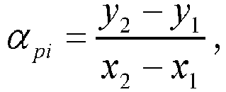
- ⁇ pi indicates the inclination (or slope) of the envelope line 141e relative to the x-axis.
- ⁇ po indicates the inclination of the envelope line 171e relative to the x-axis.
- ⁇ pi indicates the intercept of the envelope line 141e with the y-axis.
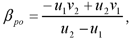
- ⁇ po indicates the intercept of the envelope line 171e with the y-axis.
- ⁇ bi indicates the intercept of the envelope line 241e with the y-axis.
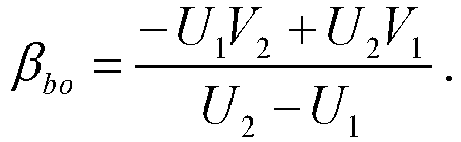
- ⁇ bo indicates the intercept of the envelope line 271e with the y-axis.
- the inner threads 14 and 24 contact each other at the same time as the outer threads 17 and 27 contact each other, thereby preventing galling on the inner threads 14 and 24 and outer threads 17 and 27. The reason for this will be described in detail below.
- the envelope line 241e of the crests 244 of the box inner perfect thread portion 241 is represented by the following expression, Expression (7).
- the envelope line 271e of the crests 274 of the box outer perfect thread portion 271 is represented by the following expression, Expression (8).
- ⁇ bo indicates the inclination of the envelope 271e relative to the x-axis.
- the pin 10 advances relative to the box 20 by the distance L1 in the direction of the pipe axis CL starting at the initiation of inner-thread make-up until the completion of inner-thread make-up.
- the pin 10 advances relative to the box 20 by the distance L2 in the direction of the pipe axis CL starting at the initiation of outer-thread make-up until the completion of outer-thread make-up.
- the pin intermediate sealing surface 16 may have a diameter smaller than that of the envelope line 271e of the crests 274 of the outer female thread 27. This will avoid a contact between the outer female thread 27 and pin intermediate sealing surface 18.
- the above-described two-step threaded connection 1 may further satisfy the following expressions, Expressions (3) and (4).
- the inner threads 14 and 24 and the outer threads 17 and 27 will have a contact length of 5 mm or more.
- the threaded connection according to the above-described embodiment may not only be applied to a coupling-type connection, but also to an integral connection.
- the nose 12, pin inner sealing surface 13, pin intermediate sealing surface 16, box inner sealing surface 23 and box intermediate sealing surface 26 may not be provided.
- test specimens with different dimensions were used to conduct repeated make-up/break-out tests as defined by the ISO 13679 standard to determine whether galling occurred.
- Each test specimen was a coupling-type threaded connection having the basic configuration shown in FIG. 1 .
- the common test conditions are provided below.
- Table 2 is a summary of the test conditions and evaluations for the various test specimens.
- Specimen Specimen 1 Specimen 2 Specimen 3 Specimen 4 Outer diameter of steel pipe 7-5/8" 7-5/8" 7-5/8" 10-1/8" Distance starting at initiation of make-up until completion inner thread L1 60.0 40.0 33.3 53.6 outer thread L2 69.7 40.0 33.3 53.6 Inner thread contact determination contact if X2>x1+L1 x1+L1 -6.1 -27.6 -37.6 -13.1 X2 -19.7 -16.0 -15.2 -8.1 determination non-contact contact contact contact contact length 11.6 22.5 5.0 Outer thread contact determination contact if U2>u1+L2 u1+L2 100.9 71.8 63.8 78.0 U2 117.0 110.3 108.7 115.7 determination contact contact contact contact contact contact length 16.1 38.6 44.9 37.7 Result of actual test galling on outer threads passed passed passed passed Other comparative inventive inventive
Landscapes
- Engineering & Computer Science (AREA)
- General Engineering & Computer Science (AREA)
- Mechanical Engineering (AREA)
- Mining & Mineral Resources (AREA)
- Life Sciences & Earth Sciences (AREA)
- Geology (AREA)
- Fluid Mechanics (AREA)
- Environmental & Geological Engineering (AREA)
- Physics & Mathematics (AREA)
- General Life Sciences & Earth Sciences (AREA)
- Geochemistry & Mineralogy (AREA)
- Non-Disconnectible Joints And Screw-Threaded Joints (AREA)
- Earth Drilling (AREA)
Abstract


Description
- The present disclosure relates to a threaded connection used to connect steel pipes.
- In oil wells, natural-gas wells etc. (hereinafter collectively referred to as "oil wells"), oil-well pipes such as casing or tubing are used to mine underground resources. An oil-well pipe is composed of a series of steel pipes connected together, where a threaded connection is used to connect such pipes.
- Such threaded connections for steel pipe are generally categorized as coupling type and integral type. A coupling-type connection connects a pair of pipes, one of which is a steel pipe and the other one is a coupling. In this case, a male thread is provided on the outer periphery of each of the ends of the steel pipe, while a female thread is provided on the inner periphery of each of the ends of the coupling. Then, a male thread of a steel pipe is screwed into a female thread of the coupling such that they are made up and connected. An integral connection connects a pair of pipes that are both steel pipes, and does not use a separate coupling. In this case, a male thread is provided on the outer periphery of one end of each steel pipe, while a female thread is provided on the inner periphery of the other end. Then, the male thread of one steel pipe is screwed into the female thread of another steel pipe such that they are made up and connected.
- A connection portion of a pipe end on which a male thread is provided includes an element to be inserted into a female thread, and thus is usually referred to as pin. A connection portion of a pipe end on which a female thread is provided includes an element for receiving a male thread, and thus is referred to as box. A pin and a box constitute ends of pipes and thus are tubular in shape.
- In recent years, more and more deep wells in harsh environments with high temperatures and high pressures have been developed, and a threaded connection for oil-well pipe used in such a well is required to have further improved sealability. Particularly, since deep wells have higher tensile/compressive loads and external pressures, the sealability against external pressures under tensile/compressive loads needs to be improved.
- A threaded connection for oil-well pipe exhibits high sealability at its seal. Generally, the sealing portion of the pin has a larger diameter than the diameter of the sealing portion of the box. Thus, when the connection is made up, these sealing portions closely contact each other in a fitting manner to achieve an interference fit, thereby forming a seal using metal-to-metal contact. The difference between the diameter of the sealing portion of the pin and the diameter of the sealing portion of the box is referred to as "seal interference". The larger the seal interference, the higher the seal contact force, providing better sealability.
- To improve the sealability against external pressures, it is effective to increase the wall thickness of that sealing portion of the pin on which external pressures act. This increases the swaging resistance of the sealing portion of the pin upon application of an external pressure to the threaded connection, thus reducing the decrease in the effective seal interference and reducing the decrease in the seal contact force. In addition, the threaded portions must have certain lengths and the shoulder surfaces must have certain areas to allow the connection to exhibit stable sealability even under high-tensile/compressive loads.
-
WO 2015/194160 (Patent Document 1) discloses a threaded connection for steel pipe that improves sealability against internal and external pressures (see paragraph [0020]). This threaded connection includes, starting from the tip of the pin (i.e., from the pipe end of the body of the oil-well pipe): shoulder surfaces, first sealing surfaces, first male/female threads, auxiliary shoulder surfaces, annular portions, second sealing surfaces, and second male/female threads (see paragraph [0063] andFIG. 6 ). - The first male thread will be hereinafter referred to as "inner male thread", the first female thread as "inner female thread", the second male thread as "outer male thread", the second female thread as "outer female thread", the inner male and female threads collectively as "inner threads", the outer male and female threads collectively as "outer threads", and the threaded connection including inner and outer threads as "two-step threaded connection".
-
JP Hei10(1998)-89554 A FIG. 1 ). This connection, too, is a "two-step threaded connection". -
WO 2017/104282 (Patent Document 3) discloses a threaded connection for steel pipe that provides good sealability and also prevents crevice corrosion (see paragraph [0017]). This document specifies such an interference δshld between the intermediate shoulders that the inner shoulders contact each other at the same time as the intermediate shoulders contact each other (see paragraphs [0050] to [0057] andFIG. 3 ). This connection, too, is a "two-step threaded connection". -
- [Patent Document 1]
WO 2015/194160 - [Patent Document 2]
JP Hei10(1998)-89554 A - [Patent Document 3]
WO 2017/104282 - [Patent Document 4]
PCT/JP2018/039964 - The inventors newly found that, upon initiation of the make-up of a two-step threaded connection, galling can easily occur on either the inner or outer threads.
- An object of the present disclosure is to provide a threaded connection for steel pipe in which galling does not easily occur on any of the inner and outer threads.
- The inventors analyzed galling that occurs on either the inner threads or outer threads upon initiation of the make-up of a two-step threaded connection to determine the reasons, and obtained the following new findings: When a two-step threaded connection is made up, the inner threads contact each other before the outer threads contact each other, or the outer threads contact each other before the inner threads contact each other. At the beginning of make-up, the threads are not in complete engagement, which means that make-up proceeds while the axes of the pin and box are not completely aligned, i.e., in a state called misalignment. Thus, if the inner threads contact first, the inner threads receive excessive loads; if the outer threads contact first, the outer threads receive excessive loads. The inner or outer threads that receive excessive loads experience locally high surface pressures such that galling can easily occur.
- A threaded connection for steel pipe according to the present disclosure includes: a tubular pin; and a tubular box, the pin being screwed into the box such that the pin and the box are made up. The pin includes: a tapered inner male thread; a tapered outer male thread; and a pin intermediate shoulder surface. The inner male thread is provided on an outer periphery of the pin and located relatively close to a tip of the pin. The outer male thread is provided on the outer periphery of the pin and located relatively close to an end of the pin opposite to the tip. The pin intermediate shoulder surface is located between the inner male thread and the outer male thread. The box includes: a tapered inner female thread; a tapered outer female thread; and a box intermediate shoulder surface. The inner female thread is provided on an inner periphery of the box to correspond to the inner male thread. The outer female thread is provided on the inner periphery of the box to correspond to the outer male thread. The box intermediate shoulder surface faces the pin intermediate shoulder surface, the box intermediate shoulder surface being in contact with the pin intermediate shoulder surface when the pin and the box are made up.
- Each of the inner male thread, the outer male thread, the inner female thread and the outer female thread includes a perfect thread portion, and each of the perfect thread portions includes an inner end located relatively close to the tip of the pin and an outer end located relatively close to the end of the pin opposite to the tip. The pin and the box, when made up, have a longitudinal cross section containing an axis of the steel pipe. An orthogonal coordinate system introduced in the longitudinal cross section has an x-axis represented by the axis of the steel pipe, a y-axis represented by a radius of the steel pipe, and an origin (0,0) represented by an intersection of a plane containing the pin intermediate shoulder surface and the box intermediate shoulder surface, on one hand, and the axis of the steel pipe, on the other hand.
- The threaded connection for steel pipe satisfies the following expressions, Expressions (1) and (2):


- The variables in Expressions (1) and (2) are defined as follows:


- (x1,y1) indicates coordinates of the inner end of the perfect thread portion of the inner male thread. (x2,y2) indicates coordinates of the outer end of the perfect thread portion of the inner male thread. (u1,v1) indicates coordinates of the inner end of the perfect thread portion of the outer male thread. (u2,v2) indicates coordinates of the outer end of the perfect thread portion of the outer male thread. (X1,Y1) indicates coordinates of the inner end of the perfect thread portion of the inner female thread. (X2,Y2) indicates coordinates of the outer end of the perfect thread portion of the inner female thread. (U1,V1) indicates coordinates of the inner end of the perfect thread portion of the outer female thread. (U2,V2) indicates coordinates of the outer end of the perfect thread portion of the outer female thread.
- In the threaded connection for steel pipe described above, the inner threads contact each other substantially at the same time as the outer threads contact each other, thereby preventing galling on the inner and outer threads.
-
- [
FIG. 1] FIG. 1 is a longitudinal cross-sectional view of a threaded connection for steel pipe according to an embodiment. - [
FIG. 2] FIG. 2 is a longitudinal cross-sectional view of the threaded connection shown inFIG. 1 as divided into the pin and box and shown in an orthogonal coordinate system. - [
FIG. 3] FIG. 3 is an enlarged view of an example of portion III inFIG. 2 . - [
FIG. 4] FIG. 4 is an enlarged view of another example of portion III inFIG. 2 . - [
FIG. 5] FIG. 5 is an enlarged view of portion V inFIG. 4 . - [
FIG. 6] FIG. 6 is a longitudinal cross-sectional view of the inner threads inFIGS. 1 and2 , showing how they move starting at the initiation of make-up until the completion of make-up. - The threaded connection for steel pipe according to the present embodiment includes: a tubular pin; and a tubular box, the pin being screwed into the box such that the pin and the box are made up. The pin includes: a tapered inner male thread; a tapered outer male thread; and a pin intermediate shoulder surface. The inner male thread is provided on an outer periphery of the pin and located relatively close to a tip of the pin. The outer male thread is provided on the outer periphery of the pin and located relatively close to an end of the pin opposite to the tip. The pin intermediate shoulder surface is located between the inner male thread and the outer male thread. The box includes: a tapered inner female thread; a tapered outer female thread; and a box intermediate shoulder surface. The inner female thread is provided on an inner periphery of the box to correspond to the inner male thread. The outer female thread is provided on the inner periphery of the box to correspond to the outer male thread. The box intermediate shoulder surface faces the pin intermediate shoulder surface, the box intermediate shoulder surface being in contact with the pin intermediate shoulder surface when the pin and the box are made up.
- Each of the inner male thread, the outer male thread, the inner female thread and the outer female thread includes a perfect thread portion, and each of the perfect thread portions includes an inner end located relatively close to the tip of the pin and an outer end located relatively close to the end of the pin opposite to the tip. The pin and the box, when made up, have a longitudinal cross section containing an axis of the steel pipe. An orthogonal coordinate system introduced in the longitudinal cross section has an x-axis represented by the axis of the steel pipe, a y-axis represented by a radius of the steel pipe, and an origin (0,0) represented by an intersection of a plane containing the pin intermediate shoulder surface and the box intermediate shoulder surface, on one hand, and the axis of the steel pipe, on the other hand.
- The threaded connection for steel pipe satisfies the following expressions, Expressions (1) and (2):


- The variables in Expressions (1) and (2) are defined as follows:




- (x1,y1) indicates coordinates of the inner end of the perfect thread portion of the inner male thread. (x2,y2) indicates coordinates of the outer end of the perfect thread portion of the inner male thread. (u1,v1) indicates coordinates of the inner end of the perfect thread portion of the outer male thread. (u2,v2) indicates coordinates of the outer end of the perfect thread portion of the outer male thread. (X1,Y1) indicates coordinates of the inner end of the perfect thread portion of the inner female thread. (X2,Y2) indicates coordinates of the outer end of the perfect thread portion of the inner female thread. (U1,V1) indicates coordinates of the inner end of the perfect thread portion of the outer female thread. (U2,V2) indicates coordinates of the outer end of the perfect thread portion of the outer female thread.
- In
Arrangement 1, the inner threads contact each other substantially at the same time as the outer threads contact each other, thereby preventing galling on the inner and outer threads. - Starting from the threaded connection for steel pipe of
Arrangement 1, the pin may further include: a nose provided at the tip of the pin; a pin inner sealing surface located between the nose and the inner male thread; and a pin intermediate sealing surface provided between the outer male thread and the pin intermediate shoulder surface. The box may further include: a box inner sealing surface facing the pin inner sealing surface, the box inner sealing surface being in contact with the pin inner sealing surface when the pin and the box are made up; and a box intermediate sealing surface facing the pin intermediate sealing surface, the box intermediate sealing surface being in contact with the pin intermediate sealing surface when the pin and the box are made up. - Starting from threaded connection for steel pipe of
Arrangement 1 or 2, the pin intermediate sealing surface may have a smaller diameter than an envelope line of a crest of the outer female thread. - Arrangement 3 prevents the outer female thread and pin intermediate sealing surface from contacting each other.
- Starting from the threaded connection for steel pipe of any one of
Arrangements 1 to 3, the threaded connection may further satisfy the following expressions, Expressions (3) and (4):

- In Arrangement 4, the inner threads may contact each other along 5 mm or more, and the outer threads may contact each other along 5 mm or more.
- Now, the present embodiment will be described in detail with reference to the drawings. The same or corresponding portions in drawings are labeled with the same characters, and the same description will not be repeated.
- Referring to
FIG. 1 , a threaded connection for steel pipe according to the present embodiment, denoted by 1, is a coupling-type threaded connection that includes atubular pin 10 and atubular box 20 to be made up on thepin 10 when thepin 10 is screwed in. - The
pin 10 includes anose 12, a tapered innermale thread 14, a tapered outermale thread 17, a pininner sealing surface 13, a pinintermediate shoulder surface 18, a pinintermediate sealing surface 16, and a pinannular portion 15a. - The
nose 12 is provided at the tip of thepin 10. The innermale thread 14 is provided on the outer periphery of thepin 10 and located relatively close to the tip of thepin 10. The outermale thread 17 is provided on the outer periphery of thepin 10 and located relatively close to the end of thepin 10 opposite to the tip. The pininner sealing surface 13 is located between thenose 12 and innermale thread 14. The pinintermediate shoulder surface 18 is located between the inner and outermale threads intermediate sealing surface 16 is located between the outermale thread 17 and pinintermediate shoulder surface 18. The pinannular portion 15a is located between the pinintermediate shoulder surface 18 and pinintermediate sealing surface 16. - The
box 20 includes arecess 22, a tapered innerfemale thread 24, a tapered outerfemale thread 27, a boxinner sealing surface 23, a boxintermediate shoulder surface 28, a boxintermediate sealing surface 26, and a boxannular portion 25a. - The
recess 22 corresponds to thenose 12. The innerfemale thread 24 is provided on the inner periphery of thebox 20 to correspond to the innermale thread 14. The outerfemale thread 27 is provided on the inner periphery of thebox 20 to correspond to the outermale thread 17. The boxinner sealing surface 23 faces the pininner sealing surface 13, and is in contact with the pininner sealing surface 13 when thepin 10 andbox 20 are made up. The boxintermediate shoulder surface 28 faces the pinintermediate shoulder surface 18, and is in contact with the pinintermediate shoulder surface 18 when thepin 10 andbox 20 are made up. The boxintermediate sealing surface 26 faces the pinintermediate sealing surface 16, and is in contact with the pinintermediate sealing surface 16 when thepin 10 andbox 20 are made up. The boxannular portion 25a faces the pinannular portion 15a, and is spaced apart from the pinannular portion 15a when thepin 10 andbox 20 are made up. - The inner male and
female threads inner threads female threads outer threads connection 1 is a two-step threaded connection including theinner threads outer threads - Each of the pin
inner sealing surface 13 and pinintermediate sealing surface 16 has the shape of a face equivalent to the periphery of a truncated cone decreasing in diameter toward the tip, or the shape obtained by combining the periphery of such a truncated cone and a face equivalent to the periphery of a solid of revolution obtained by rotating a curve, such as an arc, about the axis of the steel pipe (hereinafter sometimes simply referred to as "pipe axis"). - The
nose 12 is tubular in shape and adjacent to the pininner sealing surface 13 in the direction of the pipe axis CL. The outer peripheral surface of thenose 12 may be a taper surface with the same slope as the taper of the pininner sealing surface 13, or with a smaller (i.e., gentler) or lager (i.e., steeper) slope. More exactly, if the outer peripheral surface of thenose 12 is a taper surface, this outer peripheral surface has the shape of a face equivalent to the periphery of a truncated cone decreasing in diameter toward the tip, or the shape obtained by combining the periphery of such a truncated cone and a face equivalent to the periphery of a solid of revolution obtained by rotating a curve, such as an arc, about the pipe axis CL. - The
pin 10 further includes a pinauxiliary shoulder surface 11 provided at the tip of thepin 10. Thebox 20 further includes a boxauxiliary shoulder surface 21 adapted to face the pinauxiliary shoulder surface 11. The pinauxiliary shoulder surface 11 may or may not be in contact with the boxauxiliary shoulder surface 21 when thepin 10 andbox 20 are made up. - The pin
auxiliary shoulder surface 11 is an annular surface generally perpendicular to the pipe axis CL. More exactly, theauxiliary shoulder surface 11 is slightly inclined such that its outer periphery is located further toward the tip of thepin 10. - The
intermediate shoulder surface 18 is located between the innermale thread 14 and pinannular portion 15a. Theintermediate shoulder surface 18 is adjacent to the pinannular portion 15a. In the present embodiment, theintermediate shoulder surface 18 is an annular surface perpendicular to the pipe axis CL. Alternatively, similar to theauxiliary shoulder surface 11, theintermediate shoulder surface 18 may be slightly inclined such that its outer periphery is located further toward the tip of thepin 10. - The pin
annular portion 15a is adjacent to forward of the pinintermediate sealing surface 16 in the direction of the pipe axis CL. The innermale thread 14 is adjacent to the pinannular portion 15a. The pinannular portion 15b is adjacent to rearward of the pinintermediate sealing surface 16 in the direction of the pipe axis CL. The outermale thread 17 is adjacent to the pinannular portion 15b. The outer peripheral surface of the pinannular portion 15a may have any shape that can ensure stiffness, and may be a cylindrical surface or a taper surface with a smaller (or gentler) slope than the thread taper of the innermale thread 14, or a curved surface. The same applies to the outer peripheral surface of the pinannular portion 15b. - The box
inner sealing surface 23 protrudes toward the pininner sealing surface 13. Alternatively, the boxinner sealing surface 23 may not protrude. In such implementations, the pininner sealing surface 13 protrudes toward the boxinner sealing surface 23. - The inner male and
female threads female threads - The taper surfaces of the
inner threads outer threads inner threads outer threads pin 10 associated with the innermale thread 14 and pininner sealing surface 13 have relatively small outer diameters and thus have relatively small wall thicknesses. On the other hand, the portions of thepin 10 associated with the pininner sealing surface 16 and outermale thread 17 have relatively large outer diameters and thus have relatively large wall thicknesses. - The inner male and
female threads female threads - As the
pin 10 is screwed in, the inner sealing surfaces 13 and 23 contact each other and the intermediate sealing surfaces 16 and 26 contact each other and, when the connection is made up, each pair comes into close contact in a fitting manner to achieve an interference fit. Thus, the inner sealing surfaces 13 and 23 and the intermediate sealing surfaces 16 and 26 form an inner seal and an intermediate seal, respectively, using metal-to-metal contact. - When the connection is made up, a clearance is formed between the
nose 12 of thepin 10 and therecess 22 of thebox 20. A clearance is also formed between the pin and boxannular portions annular portions - The intermediate shoulder surfaces 18 and 28 are in contact with each other when the connection is made up. When the intermediate shoulder surfaces 18 and 28 are in press contact a tightening axial force is applied, mainly to the load flank of the outer
male thread 17. - If a pin
auxiliary shoulder surface 11 is provided on the tip of thepin 10, this reduces the damage caused by compressive loads; thus, further improvements in performance can be expected. - Referring to
FIG. 2 , the innermale thread 14 includes a perfect thread portion (hereinafter referred to as "pin inner perfect thread portion") 141. The outermale thread 17 includes a perfect thread portion (hereinafter referred to as "pin outer perfect thread portion") 171. The innerfemale thread 24 includes a perfect thread portion (hereinafter referred to as "box inner perfect thread portion") 241. The outerfemale thread 27 includes a perfect thread portion (hereinafter referred to as box outer perfect thread portion") 271. - The pin inner
perfect thread portion 141 includes aninner end 141i located relatively close to the tip of thepin 10 and an outer end 141o located relatively close to the end of thepin 10 opposite to its tip. The pin outerperfect thread portion 171 includes aninner end 171i located relatively close to the tip of thepin 10 and an outer end 171o located relatively close to the end of thepin 10 opposite to its tip. The box innerperfect thread portion 241 includes aninner end 241i located relatively close to the tip of the pin 10 (i.e., relatively close to the end of thebox 20 opposite to its tip) and an outer end 241o located relatively close to the end of thepin 10 opposite to its tip (i.e., relatively close to the tip of the box 20). The box outerperfect thread portion 271 includes aninner end 271i located relatively close to the tip of the pin 10 (i.e., relatively close to the end of thebox 20 opposite to its tip) and an outer end 271o located relatively close to the end of thepin 10 opposite to its tip (i.e., relatively close to the tip of the box 20). - The inner
male thread 14 further includes a bevel (hereinafter referred to as "pin inner bevel") 142. The outermale thread 17 further includes an imperfect thread portion (hereinafter referred to as "pin outer imperfect thread portion") 172 and a bevel (hereinafter referred to as "pin outer bevel") 173. The innerfemale thread 24 further includes bevels (hereinafter referred to as "box inner bevels") 242 and 243. The outerfemale thread 27 includes an imperfect thread portion (hereinafter referred to as box outer imperfect thread portion") 272. - In a perfect thread portion, both the crest (i.e., thread ridge) and root (i.e., thread groove) have a perfect, predetermined shape. In an imperfect thread portion, the crest (i.e., thread ridge) or root (i.e., thread groove) have an imperfect shape. A bevel is also called "inclined surface", and is a type of imperfect thread portion.
- Table 1 shows combinations of a perfect thread portion and an imperfect thread portion fitted together.
[Table 1] Pin Box Crest of male thread (root of female thread) Root of male thread (crest of female thread) perfect thread portion perfect thread portion non-contact contact perfect thread portion imperfect thread portion non-contact non-contact imperfect thread portion perfect thread portion non-contact contact imperfect thread portion imperfect thread portion non-contact non-contact - As shown in Table 1, according to the present embodiment, the
crests male threads roots 247 and 276 of thefemale threads perfect thread portions box 20 are concerned, the roots of themale threads crests female threads - The
inner end 141i of the pin innerperfect thread portion 141 is located at the intersection of theenvelope line 141e of thecrests 144 of the pin innerperfect thread portion 141 and theenvelope line 142e of thecrests 145 of the pininner bevel 142. The outer end 141o of the pin innerperfect thread portion 141 is located at the intersection of theenvelope line 141e of the crests of the pin innerperfect thread portion 141 and theextension line 143e of theouter periphery 143 of thepin 10. Theinner end 171i of the pin outerperfect thread portion 171 is located at the intersection of theenvelope line 171e of thecrests 174 of the pin outerperfect thread portion 171 and theenvelope line 173e of thecrests 175 of the pinouter bevel 173. The outer end 171o of the pin outerperfect thread portion 171 is located at the intersection of theenvelope line 171e of thecrests 174 of the pin outerperfect thread portion 171 and theenvelope line 172e of thecrests 176 of the pin outer imperfect thread portion 172 (or extension line of theouter periphery 177 of thepin 10, which is the same as the crests 176). - The
inner end 241i of the box innerperfect thread portion 241 is located at the intersection of theenvelope line 241e of thecrests 244 of the box innerperfect thread portion 241 and theenvelope line 242e of thecrests 245 of the boxinner bevel 242. The outer end 241o of the box innerperfect thread portion 241 is located at the intersection of theenvelope line 241e of thecrests 244 of the box innerperfect thread portion 241 and theextension line 243e of thecrests 246 of the boxinner bevel 243. Theinner end 271i of the box outerperfect thread portion 271 is located at the intersection of theenvelope line 271e of thecrests 274 of the box outerperfect thread portion 271 and theenvelope line 272e of thecrests 275 of the box outerimperfect thread portion 272. The outer end 271o of the box outerperfect thread portion 271 is located at the intersection of theenvelope line 271e of thecrests 274 of the box outerperfect thread portion 271 and theextension line 273e of theend surface 273 of thebox 20. - The envelope lines and extension lines are represented as lines in a cross-sectional view; however, since the
pin 10 andbox 20 are tubular in shape, they are, in reality, planes. Accordingly, although the inner and outer ends are represented as points in a cross-sectional view, they are, in reality, lines. - More specifically, the
envelope lines crests crests 174 of the pin outerperfect thread portion 171 may be tapered, as shown inFIG. 3 , or may be step-wise shaped, as shown inFIG. 4 . - If the
crests 174 are tapered as shown inFIG. 3 , theroots 178 are also tapered. The taper angles of thecrests 174 androots 178 are equal to the taper angle of the outermale thread 17. In a cross-sectional view, thecrests 174 are positioned on one and the same straight line. This straight line defines theenvelope line 171e of thecrests 174. As discussed above, the outer end 171o of the pin outerperfect thread portion 171 is located at the intersection of theenvelope line 171e of thecrests 174 of the pin outerperfect thread portion 171 and theenvelope line 172e of thecrests 176 of the pin outerimperfect thread portion 172, i.e.,extension line 172e of theouter periphery 177 of thepin 10. - On the other hand, if the
crests 174 are step-wise shaped as shown inFIG. 4 , theroots 178 are also step-wise shaped. Thecrests 174 androots 178 are parallel to the pipe axis CL. In a cross-sectional view, thecrests 174 are not positioned on one and the same straight line. Thus, in this case, theenvelope line 171e is defined as a straight line passing through the intersection CP of theextension line 174e of thecrests 174 and theextension line 179e of astab flank 179, as shown inFIG. 5 . Astab flank 179 is the one of the flanks of the outermale thread 17 that faces the tip of thepin 10. Again, as shown inFIG. 4 , the outer end 171o of the pin outerperfect thread portion 171 is located at the intersection of theenvelope line 171e of thecrests 174 of the pin outerperfect thread portion 171 and theenvelope line 172e of thecrests 176 of the pin outerimperfect thread portion 172, i.e.,extension line 172e of theouter periphery 177 of thepin 10. - As shown in
FIG. 1 , thepin 10 andbox 20 that have been made up have a longitudinal cross section containing the pipe axis CL. As shown inFIG. 2 , an orthogonal coordinate system introduced in the longitudinal cross-sectional view has an x-axis represented by the pipe axis CL, a y-axis represented by a radius of the steel pipe, and an origin (0,0) represented by the intersection CP of a plane SP containing the pinintermediate shoulder surface 18 and boxintermediate shoulder surface 28, and the pipe axis CL. - This two-step threaded
connection 1 satisfies the following expressions, Expressions (1) and (2):

- The variables in Expressions (1) and (2) are defined as follows:




- The coordinates in
FIG. 2 are defined as follows: - (x1,y1): coordinates of the
inner end 141i of the pin innerperfect thread portion 141; - (x2,y2): coordinates of the outer end 141o of the pin inner
perfect thread portion 141; - (u1,v1): coordinates of the
inner end 171i of the pin outerperfect thread portion 171; - (u2,v2): coordinates of the outer end 171o of the pin outer
perfect thread portion 171; - (X1,Y1): coordinates of the
inner end 241i of the box innerperfect thread portion 241; - (X2,Y2): coordinates of the outer end 241o of the box inner
perfect thread portion 241; - (U1,V1): coordinates of the
inner end 271i of the box outerperfect thread portion 271; and - (U2,V2): coordinates of the outer end 271o of the box outer
perfect thread portion 271. - In the above expressions, L1 is the distance that the
pin 10 advances relative to thebox 20 in the direction of the pipe axis CL during make-up of theinner threads envelope line 141e of thecrests 144 of the pin innerperfect thread portion 141 reaches theenvelope line 241e of thecrests 244 of the box innerperfect thread portion 241; hereinafter referred to as "at initiation of inner-thread make-up") until the completion of make-up (i.e., when the pinintermediate shoulder surface 18 reaches the box intermediate shoulder surface 28). - L2 is the distance that the
pin 10 advances relative to thebox 20 in the direction of the pipe axis CL during make-up of theouter threads envelope line 171e of thecrests 174 of the pin outerperfect thread portion 171 reaches theenvelope line 271e of thecrests 274 of the box outerperfect thread portion 271; hereinafter referred to as "at initiation of outer-thread make-up") until the completion of make-up (i.e., when the pinintermediate shoulder surface 18 reaches the box intermediate shoulder surface 28). - αpi indicates the inclination (or slope) of the
envelope line 141e relative to the x-axis. αpo indicates the inclination of theenvelope line 171e relative to the x-axis. βpi indicates the intercept of theenvelope line 141e with the y-axis. βpo indicates the intercept of theenvelope line 171e with the y-axis. βbi indicates the intercept of theenvelope line 241e with the y-axis. βbo indicates the intercept of theenvelope line 271e with the y-axis. - In the two-step threaded
connection 1 having the above-described configuration, theinner threads outer threads inner threads outer threads - The
envelope line 141e of thecrests 144 of the pin innerperfect thread portion 141 is represented by the following expression, Expression (5):
- The
envelope line 171e of thecrests 174 of the pin outerperfect thread portion 171 is represented by the following expression, Expression (6):
- The
envelope line 241e of thecrests 244 of the box innerperfect thread portion 241 is represented by the following expression, Expression (7). In Expression (7), αbi indicates the inclination of theenvelope line 241e relative to the x-axis:
- The
envelope line 271e of thecrests 274 of the box outerperfect thread portion 271 is represented by the following expression, Expression (8). In Expression (8), αbo indicates the inclination of theenvelope 271e relative to the x-axis.
- Referring to
FIG. 6 , during make-up of theinner threads pin 10 advances relative to thebox 20 by the distance L1 in the direction of the pipe axis CL starting at the initiation of inner-thread make-up until the completion of inner-thread make-up. The distance L1 is represented by the following expressions, Expressions (9) and (10):

- Similarly, during make-up of the
outer threads pin 10 advances relative to thebox 20 by the distance L2 in the direction of the pipe axis CL starting at the initiation of outer-thread make-up until the completion of outer-thread make-up. The distance L2 is represented by the following expressions, Expressions (11) and (12):

- Since the taper angles of the
pin 10 andbox 20 are substantially equal, αPi≈αbi and αpo≈αbo are true. - In order that the
inner threads outer threads inner end 141i of the pin innerperfect thread portion 141 be smaller than the x coordinate (X2) of the outer end 241o of the box innerperfect thread portion 241 and, at the initiation of outer-thread make-up, the x coordinate (u1) of theinner end 171i of the pin outerperfect thread portion 171 be smaller than the x coordinate (U2) of the outer end 271o of the box outerperfect thread portion 271, and thus it is only required that Expressions (1) and (2) be satisfied:

- In the above-described two-step threaded
connection 1, the pinintermediate sealing surface 16 may have a diameter smaller than that of theenvelope line 271e of thecrests 274 of the outerfemale thread 27. This will avoid a contact between the outerfemale thread 27 and pinintermediate sealing surface 18. - The above-described two-step threaded
connection 1 may further satisfy the following expressions, Expressions (3) and (4). In this case, theinner threads outer threads 

- The threaded connection according to the above-described embodiment may not only be applied to a coupling-type connection, but also to an integral connection.
- In the above-described two-step threaded
connection 1, thenose 12, pininner sealing surface 13, pinintermediate sealing surface 16, boxinner sealing surface 23 and boxintermediate sealing surface 26 may not be provided. - Otherwise, the present disclosure is not limited to the above-described embodiment, and various modifications are possible without departing from the spirit of the present disclosure.
- To verity the effects of the threaded connection for steel pipe according to the present embodiment, actual samples were used to conduct galling-resistance evaluation tests.
- A plurality of test specimens with different dimensions were used to conduct repeated make-up/break-out tests as defined by the ISO 13679 standard to determine whether galling occurred. Each test specimen was a coupling-type threaded connection having the basic configuration shown in
FIG. 1 . The common test conditions are provided below. -
- 7-5/8 [inch] × 1.06 [inch] (outer diameter: 193.7 [mm], wall thickness: 27.0 [mm])
- 10-1/8 [inch] × 0.8 [inch] (outer diameter: 257.2 [mm], wall thickness: 20.3 [mm])
- P110 in accordance with the API standards (carbon steel with a nominal yield stress of 110 [ksi])
- Table 2 is a summary of the test conditions and evaluations for the various test specimens.
[Table 2] Specimen Specimen 1 Specimen 2 Specimen 3 Specimen 4 Outer diameter of steel pipe 7-5/8" 7-5/8" 7-5/8" 10-1/8" Distance starting at initiation of make-up until completion inner thread L1 60.0 40.0 33.3 53.6 outer thread L2 69.7 40.0 33.3 53.6 Inner thread contact determination contact if X2>x1+L1 x1+L1 -6.1 -27.6 -37.6 -13.1 X2 -19.7 -16.0 -15.2 -8.1 determination non-contact contact contact contact contact length 11.6 22.5 5.0 Outer thread contact determination contact if U2>u1+L2 u1+L2 100.9 71.8 63.8 78.0 U2 117.0 110.3 108.7 115.7 determination contact contact contact contact contact length 16.1 38.6 44.9 37.7 Result of actual test galling on outer threads passed passed passed Other comparative inventive inventive inventive - In
Specimen 1, at the initiation of make-up, only the outer threads were in contact and the inner threads were not in contact, resulting in an unstable contact. As such, as the make-up proceeded, excess loads were applied to the outer threads such that galling occurred on the outer threads upon the first make-up/break-out test. - In Specimens 2 to 4, the inner threads started to be in contact substantially at the same time as the outer threads, resulting in a stable contact from the initiation of make-up until the completion of make-up. As such, uniform loads were applied to both the inner and outer threads and no galling occurred, where three make-up/break-out tests were successful.
-
- 10:
- pin
- 12:
- nose
- 13:
- pin inner sealing surface
- 14:
- inner male thread
- 16:
- pin intermediate sealing surface
- 17:
- outer male thread
- 18:
- pin intermediate shoulder surface
- 20:
- box
- 22:
- recess
- 23:
- box inner sealing surface
- 24:
- inner female thread
- 26:
- box intermediate sealing surface
- 27:
- outer female thread
- 28:
- box intermediate shoulder surface
- 141:
- pin inner perfect thread portion
- 171:
- pin outer perfect thread portion
- 241:
- box inner perfect thread portion
- 271:
- box outer perfect thread portion
- 141i, 171i, 241i, 271i:
- inner ends
- 141o, 171o, 241o, 271o:
- outer ends
Claims (4)
- A threaded connection for steel pipe, comprising:a tubular pin; anda tubular box, the pin being screwed into the box such that the pin and the box are made up,the pin including:a tapered inner male thread provided on an outer periphery of the pin and located relatively close to a tip of the pin;a tapered outer male thread provided on the outer periphery of the pin and located relatively close to an end of the pin opposite to the tip; anda pin intermediate shoulder surface located between the inner male thread and the outer male thread,the box including:a tapered inner female thread provided on an inner periphery of the box to correspond to the inner male thread;a tapered outer female thread provided on the inner periphery of the box to correspond to the outer male thread; anda box intermediate shoulder surface facing the pin intermediate shoulder surface, the box intermediate shoulder surface being in contact with the pin intermediate shoulder surface when the pin and the box are made up,wherein each of the inner male thread, the outer male thread, the inner female thread and the outer female thread includes a perfect thread portion, and each of the perfect thread portions includes an inner end located relatively close to the tip of the pin and an outer end located relatively close to the end of the pin opposite to the tip,the pin and the box, when made up, have a longitudinal cross section containing an axis of the steel pipe, and an orthogonal coordinate system introduced in the longitudinal cross section has an x-axis represented by the axis of the steel pipe, a y-axis represented by a radius of the steel pipe, and an origin (0,0) represented by an intersection of a plane containing the pin intermediate shoulder surface and the box intermediate shoulder surface, on one hand, and the axis of the steel pipe, on the other hand, andthe threaded connection satisfies the following expressions, Expressions (1) and (2):




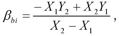
 (x1,y1) denote the coordinates of the inner end of the perfect thread portion of the inner male thread;(x2,y2) denote the coordinates of the outer end of the perfect thread portion of the inner male thread;(u1,v1) denote the coordinates of the inner end of the perfect thread portion of the outer male thread;(u2,V2) denote the coordinates of the outer end of the perfect thread portion of the outer male thread;(X1,Y1) denote the coordinates of the inner end of the perfect thread portion of the inner female thread;(X2,Y2) denote the coordinates of the outer end of the perfect thread portion of the inner female thread;(U1,V1) denote the coordinates of the inner end of the perfect thread portion of the outer female thread; and(U2,V2) denote the coordinates of the outer end of the perfect thread portion of the outer female thread.
 - The threaded connection for steel pipe according to claim 1, wherein the pin further includes:a nose provided at the tip of the pin;a pin inner sealing surface located between the nose and the inner male thread; anda pin intermediate sealing surface provided between the outer male thread and the pin intermediate shoulder surface, andthe box further includes:a box inner sealing surface facing the pin inner sealing surface, the box inner sealing surface being in contact with the pin inner sealing surface when the pin and the box are made up; anda box intermediate sealing surface facing the pin intermediate sealing surface, the box intermediate sealing surface being in contact with the pin intermediate sealing surface when the pin and the box are made up.
- The threaded connection for steel pipe according to claim 1 or 2, wherein the pin intermediate sealing surface has a smaller diameter than an envelope line of a crest of the outer female thread.
- The threaded connection for steel pipe according to any one of claims 1 to 3, further satisfying the following expressions, Expressions (3) and (4):


Applications Claiming Priority (2)
| Application Number | Priority Date | Filing Date | Title |
|---|---|---|---|
| JP2018240644 | 2018-12-25 | ||
| PCT/JP2019/050190 WO2020137917A1 (en) | 2018-12-25 | 2019-12-20 | Steel-pipe threaded joint |
Publications (4)
| Publication Number | Publication Date |
|---|---|
| EP3904745A1 true EP3904745A1 (en) | 2021-11-03 |
| EP3904745A4 EP3904745A4 (en) | 2022-02-16 |
| EP3904745B1 EP3904745B1 (en) | 2023-09-06 |
| EP3904745C0 EP3904745C0 (en) | 2023-09-06 |
Family
ID=71127711
Family Applications (1)
| Application Number | Title | Priority Date | Filing Date |
|---|---|---|---|
| EP19903256.6A Active EP3904745B1 (en) | 2018-12-25 | 2019-12-20 | Threaded connection for steel pipe |
Country Status (10)
| Country | Link |
|---|---|
| US (1) | US11892106B2 (en) |
| EP (1) | EP3904745B1 (en) |
| JP (1) | JP7150878B2 (en) |
| CN (1) | CN113227626B (en) |
| AR (1) | AR117733A1 (en) |
| BR (1) | BR112021007350B1 (en) |
| CA (1) | CA3120752C (en) |
| MX (1) | MX2021006782A (en) |
| RU (1) | RU2768626C1 (en) |
| WO (1) | WO2020137917A1 (en) |
Families Citing this family (4)
| Publication number | Priority date | Publication date | Assignee | Title |
|---|---|---|---|---|
| JP6888687B2 (en) * | 2018-10-10 | 2021-06-16 | Jfeスチール株式会社 | Threaded joint |
| EP3798409B1 (en) * | 2019-09-24 | 2023-07-12 | Vallourec Oil And Gas France | Threaded connection including an intermediate shoulder |
| CN114320175B (en) * | 2020-09-29 | 2024-05-14 | 宝山钢铁股份有限公司 | Quick screwing-up threaded joint for anti-sticking |
| AR133722A1 (en) * | 2023-09-05 | 2025-10-29 | Hydril Co | CIRCULAR LOCKING SEAL |
Family Cites Families (19)
| Publication number | Priority date | Publication date | Assignee | Title |
|---|---|---|---|---|
| US4795200A (en) * | 1986-12-04 | 1989-01-03 | Hydril Company | Lengthened tubular pin member nose for improving sealing integrity and bearing forces |
| US6027145A (en) * | 1994-10-04 | 2000-02-22 | Nippon Steel Corporation | Joint for steel pipe having high galling resistance and surface treatment method thereof |
| JPH1089554A (en) | 1996-09-17 | 1998-04-10 | Sumitomo Metal Ind Ltd | Slim type threaded joint for oil country tubular goods having different strength portions and method of manufacturing the same |
| IT1309704B1 (en) | 1999-02-19 | 2002-01-30 | Eni Spa | INTEGRAL JUNCTION OF TWO PIPES |
| US7690696B2 (en) * | 1999-04-19 | 2010-04-06 | Hydril Company | Wedge thread with torque shoulder |
| BR0010192A (en) * | 1999-04-30 | 2002-05-14 | Grant Prideco Inc | Threaded connection with high compression capacity |
| UA82694C2 (en) | 2003-06-06 | 2008-05-12 | Sumitomo Metal Ind | Threaded joint for steel pipes |
| US7780202B2 (en) * | 2007-09-05 | 2010-08-24 | Grant Prideco, Lp | Oilfield tubular connection with increased compression capacity |
| US10215314B2 (en) | 2010-08-23 | 2019-02-26 | Vallourec Oil And Gas France | Tubular threaded connection |
| US20120074693A1 (en) * | 2010-09-24 | 2012-03-29 | Hydril Company | Step-to-step wedge thread connections and related methods |
| JP5923911B2 (en) * | 2011-03-22 | 2016-05-25 | Jfeスチール株式会社 | Threaded joints for steel pipes |
| EA033336B1 (en) | 2014-06-20 | 2019-09-30 | Ниппон Стил Энд Сумитомо Метал Корпорейшн | Threaded joint for steel pipes |
| EP3128119A1 (en) * | 2015-08-05 | 2017-02-08 | Hydril Company | Threaded tubular connection |
| UA119127C2 (en) | 2015-12-15 | 2019-04-25 | Ніппон Стіл Енд Сумітомо Метал Корпорейшн | RIVER CONNECTION FOR STEEL PIPE |
| CA3011204C (en) | 2016-01-25 | 2020-08-18 | Nippon Steel & Sumitomo Metal Corporation | Threaded joint for steel pipe |
| JP6187724B1 (en) * | 2016-02-19 | 2017-08-30 | Jfeスチール株式会社 | Threaded joint for oil well pipe |
| CA3031919C (en) * | 2016-09-30 | 2021-02-02 | Jfe Steel Corporation | Threaded joint for oil well steel pipe |
| BR112020006152B1 (en) | 2017-11-09 | 2023-02-07 | Nippon Steel Corporation | THREADED CONNECTION FOR STEEL PIPE |
| PL3572612T3 (en) * | 2018-05-25 | 2021-04-19 | Vallourec Oil And Gas France | Threaded pipe connection |
-
2019
- 2019-12-20 EP EP19903256.6A patent/EP3904745B1/en active Active
- 2019-12-20 CA CA3120752A patent/CA3120752C/en active Active
- 2019-12-20 RU RU2021118282A patent/RU2768626C1/en active
- 2019-12-20 AR ARP190103833A patent/AR117733A1/en active IP Right Grant
- 2019-12-20 JP JP2020563221A patent/JP7150878B2/en active Active
- 2019-12-20 CN CN201980085638.0A patent/CN113227626B/en active Active
- 2019-12-20 WO PCT/JP2019/050190 patent/WO2020137917A1/en not_active Ceased
- 2019-12-20 BR BR112021007350-7A patent/BR112021007350B1/en active IP Right Grant
- 2019-12-20 US US17/294,474 patent/US11892106B2/en active Active
- 2019-12-20 MX MX2021006782A patent/MX2021006782A/en unknown
Also Published As
| Publication number | Publication date |
|---|---|
| BR112021007350B1 (en) | 2023-12-05 |
| JP7150878B2 (en) | 2022-10-11 |
| CN113227626B (en) | 2022-11-29 |
| CN113227626A (en) | 2021-08-06 |
| AR117733A1 (en) | 2021-08-25 |
| MX2021006782A (en) | 2021-07-15 |
| EP3904745B1 (en) | 2023-09-06 |
| JPWO2020137917A1 (en) | 2021-09-09 |
| US20220010894A1 (en) | 2022-01-13 |
| EP3904745C0 (en) | 2023-09-06 |
| WO2020137917A1 (en) | 2020-07-02 |
| RU2768626C1 (en) | 2022-03-24 |
| BR112021007350A2 (en) | 2021-07-20 |
| CA3120752C (en) | 2023-06-27 |
| EP3904745A4 (en) | 2022-02-16 |
| CA3120752A1 (en) | 2020-07-02 |
| US11892106B2 (en) | 2024-02-06 |
Similar Documents
| Publication | Publication Date | Title |
|---|---|---|
| EP3708892B1 (en) | Threaded connection for steel pipe | |
| EP3904745B1 (en) | Threaded connection for steel pipe | |
| CN102678070B (en) | Pipe threaded joints | |
| EP4012239B1 (en) | Threaded connection for steel pipe | |
| CA3145225C (en) | Threaded connection | |
| CN113279704B (en) | Oil sleeve joint and oil sleeve assembly | |
| EP4083369B1 (en) | Threaded joint for pipes | |
| EP3842680A1 (en) | Threaded joint for steel pipes | |
| EP4092302B1 (en) | Threaded connection for pipe | |
| OA20943A (en) | Threaded coupling for steel pipe | |
| EA043019B1 (en) | THREADED CONNECTION | |
| JP2000028054A (en) | Threaded fittings for oil country tubular goods |
Legal Events
| Date | Code | Title | Description |
|---|---|---|---|
| STAA | Information on the status of an ep patent application or granted ep patent |
Free format text: STATUS: THE INTERNATIONAL PUBLICATION HAS BEEN MADE |
|
| PUAI | Public reference made under article 153(3) epc to a published international application that has entered the european phase |
Free format text: ORIGINAL CODE: 0009012 |
|
| STAA | Information on the status of an ep patent application or granted ep patent |
Free format text: STATUS: REQUEST FOR EXAMINATION WAS MADE |
|
| 17P | Request for examination filed |
Effective date: 20210401 |
|
| AK | Designated contracting states |
Kind code of ref document: A1 Designated state(s): AL AT BE BG CH CY CZ DE DK EE ES FI FR GB GR HR HU IE IS IT LI LT LU LV MC MK MT NL NO PL PT RO RS SE SI SK SM TR |
|
| RIC1 | Information provided on ipc code assigned before grant |
Ipc: F16L 15/00 20060101ALI20220103BHEP Ipc: E21B 17/042 20060101ALI20220103BHEP Ipc: F16L 15/04 20060101AFI20220103BHEP |
|
| A4 | Supplementary search report drawn up and despatched |
Effective date: 20220118 |
|
| DAV | Request for validation of the european patent (deleted) | ||
| DAX | Request for extension of the european patent (deleted) | ||
| GRAP | Despatch of communication of intention to grant a patent |
Free format text: ORIGINAL CODE: EPIDOSNIGR1 |
|
| STAA | Information on the status of an ep patent application or granted ep patent |
Free format text: STATUS: GRANT OF PATENT IS INTENDED |
|
| INTG | Intention to grant announced |
Effective date: 20230614 |
|
| GRAS | Grant fee paid |
Free format text: ORIGINAL CODE: EPIDOSNIGR3 |
|
| GRAA | (expected) grant |
Free format text: ORIGINAL CODE: 0009210 |
|
| STAA | Information on the status of an ep patent application or granted ep patent |
Free format text: STATUS: THE PATENT HAS BEEN GRANTED |
|
| AK | Designated contracting states |
Kind code of ref document: B1 Designated state(s): AL AT BE BG CH CY CZ DE DK EE ES FI FR GB GR HR HU IE IS IT LI LT LU LV MC MK MT NL NO PL PT RO RS SE SI SK SM TR |
|
| REG | Reference to a national code |
Ref country code: GB Ref legal event code: FG4D |
|
| REG | Reference to a national code |
Ref country code: CH Ref legal event code: EP |
|
| REG | Reference to a national code |
Ref country code: IE Ref legal event code: FG4D |
|
| REG | Reference to a national code |
Ref country code: DE Ref legal event code: R096 Ref document number: 602019037147 Country of ref document: DE |
|
| U01 | Request for unitary effect filed |
Effective date: 20231004 |
|
| REG | Reference to a national code |
Ref country code: NO Ref legal event code: T2 Effective date: 20230906 |
|
| U07 | Unitary effect registered |
Designated state(s): AT BE BG DE DK EE FI FR IT LT LU LV MT NL PT SE SI Effective date: 20231018 |
|
| U20 | Renewal fee for the european patent with unitary effect paid |
Year of fee payment: 5 Effective date: 20231116 |
|
| PG25 | Lapsed in a contracting state [announced via postgrant information from national office to epo] |
Ref country code: GR Free format text: LAPSE BECAUSE OF FAILURE TO SUBMIT A TRANSLATION OF THE DESCRIPTION OR TO PAY THE FEE WITHIN THE PRESCRIBED TIME-LIMIT Effective date: 20231207 |
|
| PG25 | Lapsed in a contracting state [announced via postgrant information from national office to epo] |
Ref country code: RS Free format text: LAPSE BECAUSE OF FAILURE TO SUBMIT A TRANSLATION OF THE DESCRIPTION OR TO PAY THE FEE WITHIN THE PRESCRIBED TIME-LIMIT Effective date: 20230906 Ref country code: HR Free format text: LAPSE BECAUSE OF FAILURE TO SUBMIT A TRANSLATION OF THE DESCRIPTION OR TO PAY THE FEE WITHIN THE PRESCRIBED TIME-LIMIT Effective date: 20230906 Ref country code: GR Free format text: LAPSE BECAUSE OF FAILURE TO SUBMIT A TRANSLATION OF THE DESCRIPTION OR TO PAY THE FEE WITHIN THE PRESCRIBED TIME-LIMIT Effective date: 20231207 |
|
| PG25 | Lapsed in a contracting state [announced via postgrant information from national office to epo] |
Ref country code: IS Free format text: LAPSE BECAUSE OF FAILURE TO SUBMIT A TRANSLATION OF THE DESCRIPTION OR TO PAY THE FEE WITHIN THE PRESCRIBED TIME-LIMIT Effective date: 20240106 |
|
| PG25 | Lapsed in a contracting state [announced via postgrant information from national office to epo] |
Ref country code: ES Free format text: LAPSE BECAUSE OF FAILURE TO SUBMIT A TRANSLATION OF THE DESCRIPTION OR TO PAY THE FEE WITHIN THE PRESCRIBED TIME-LIMIT Effective date: 20230906 |
|
| PG25 | Lapsed in a contracting state [announced via postgrant information from national office to epo] |
Ref country code: SM Free format text: LAPSE BECAUSE OF FAILURE TO SUBMIT A TRANSLATION OF THE DESCRIPTION OR TO PAY THE FEE WITHIN THE PRESCRIBED TIME-LIMIT Effective date: 20230906 Ref country code: IS Free format text: LAPSE BECAUSE OF FAILURE TO SUBMIT A TRANSLATION OF THE DESCRIPTION OR TO PAY THE FEE WITHIN THE PRESCRIBED TIME-LIMIT Effective date: 20240106 Ref country code: ES Free format text: LAPSE BECAUSE OF FAILURE TO SUBMIT A TRANSLATION OF THE DESCRIPTION OR TO PAY THE FEE WITHIN THE PRESCRIBED TIME-LIMIT Effective date: 20230906 Ref country code: CZ Free format text: LAPSE BECAUSE OF FAILURE TO SUBMIT A TRANSLATION OF THE DESCRIPTION OR TO PAY THE FEE WITHIN THE PRESCRIBED TIME-LIMIT Effective date: 20230906 Ref country code: SK Free format text: LAPSE BECAUSE OF FAILURE TO SUBMIT A TRANSLATION OF THE DESCRIPTION OR TO PAY THE FEE WITHIN THE PRESCRIBED TIME-LIMIT Effective date: 20230906 |
|
| PG25 | Lapsed in a contracting state [announced via postgrant information from national office to epo] |
Ref country code: PL Free format text: LAPSE BECAUSE OF FAILURE TO SUBMIT A TRANSLATION OF THE DESCRIPTION OR TO PAY THE FEE WITHIN THE PRESCRIBED TIME-LIMIT Effective date: 20230906 |
|
| REG | Reference to a national code |
Ref country code: DE Ref legal event code: R097 Ref document number: 602019037147 Country of ref document: DE |
|
| PLBE | No opposition filed within time limit |
Free format text: ORIGINAL CODE: 0009261 |
|
| STAA | Information on the status of an ep patent application or granted ep patent |
Free format text: STATUS: NO OPPOSITION FILED WITHIN TIME LIMIT |
|
| REG | Reference to a national code |
Ref country code: CH Ref legal event code: PL |
|
| 26N | No opposition filed |
Effective date: 20240607 |
|
| PG25 | Lapsed in a contracting state [announced via postgrant information from national office to epo] |
Ref country code: MC Free format text: LAPSE BECAUSE OF FAILURE TO SUBMIT A TRANSLATION OF THE DESCRIPTION OR TO PAY THE FEE WITHIN THE PRESCRIBED TIME-LIMIT Effective date: 20230906 |
|
| PG25 | Lapsed in a contracting state [announced via postgrant information from national office to epo] |
Ref country code: MC Free format text: LAPSE BECAUSE OF FAILURE TO SUBMIT A TRANSLATION OF THE DESCRIPTION OR TO PAY THE FEE WITHIN THE PRESCRIBED TIME-LIMIT Effective date: 20230906 |
|
| REG | Reference to a national code |
Ref country code: IE Ref legal event code: MM4A |
|
| PG25 | Lapsed in a contracting state [announced via postgrant information from national office to epo] |
Ref country code: IE Free format text: LAPSE BECAUSE OF NON-PAYMENT OF DUE FEES Effective date: 20231220 |
|
| PG25 | Lapsed in a contracting state [announced via postgrant information from national office to epo] |
Ref country code: CH Free format text: LAPSE BECAUSE OF NON-PAYMENT OF DUE FEES Effective date: 20231231 |
|
| PG25 | Lapsed in a contracting state [announced via postgrant information from national office to epo] |
Ref country code: IE Free format text: LAPSE BECAUSE OF NON-PAYMENT OF DUE FEES Effective date: 20231220 Ref country code: CH Free format text: LAPSE BECAUSE OF NON-PAYMENT OF DUE FEES Effective date: 20231231 |
|
| U20 | Renewal fee for the european patent with unitary effect paid |
Year of fee payment: 6 Effective date: 20241107 |
|
| PGFP | Annual fee paid to national office [announced via postgrant information from national office to epo] |
Ref country code: NO Payment date: 20241211 Year of fee payment: 6 |
|
| PGFP | Annual fee paid to national office [announced via postgrant information from national office to epo] |
Ref country code: GB Payment date: 20241031 Year of fee payment: 6 |
|
| PGFP | Annual fee paid to national office [announced via postgrant information from national office to epo] |
Ref country code: RO Payment date: 20241114 Year of fee payment: 6 |
|
| PG25 | Lapsed in a contracting state [announced via postgrant information from national office to epo] |
Ref country code: CY Free format text: LAPSE BECAUSE OF FAILURE TO SUBMIT A TRANSLATION OF THE DESCRIPTION OR TO PAY THE FEE WITHIN THE PRESCRIBED TIME-LIMIT; INVALID AB INITIO Effective date: 20191220 |
|
| PG25 | Lapsed in a contracting state [announced via postgrant information from national office to epo] |
Ref country code: HU Free format text: LAPSE BECAUSE OF FAILURE TO SUBMIT A TRANSLATION OF THE DESCRIPTION OR TO PAY THE FEE WITHIN THE PRESCRIBED TIME-LIMIT; INVALID AB INITIO Effective date: 20191220 |
|
| PG25 | Lapsed in a contracting state [announced via postgrant information from national office to epo] |
Ref country code: TR Free format text: LAPSE BECAUSE OF FAILURE TO SUBMIT A TRANSLATION OF THE DESCRIPTION OR TO PAY THE FEE WITHIN THE PRESCRIBED TIME-LIMIT Effective date: 20230906 |