WO2017104282A1 - 鋼管用ねじ継手 - Google Patents
鋼管用ねじ継手 Download PDFInfo
- Publication number
- WO2017104282A1 WO2017104282A1 PCT/JP2016/082567 JP2016082567W WO2017104282A1 WO 2017104282 A1 WO2017104282 A1 WO 2017104282A1 JP 2016082567 W JP2016082567 W JP 2016082567W WO 2017104282 A1 WO2017104282 A1 WO 2017104282A1
- Authority
- WO
- WIPO (PCT)
- Prior art keywords
- pin
- shoulder
- box
- contact
- shoulder surface
- Prior art date
Links
- 229910000831 Steel Inorganic materials 0.000 title claims abstract description 38
- 239000010959 steel Substances 0.000 title claims abstract description 38
- 238000007789 sealing Methods 0.000 claims abstract description 41
- 238000000034 method Methods 0.000 claims description 15
- 230000008569 process Effects 0.000 claims description 14
- 238000005260 corrosion Methods 0.000 abstract description 12
- 230000007797 corrosion Effects 0.000 abstract description 12
- 238000004458 analytical method Methods 0.000 description 15
- 230000007423 decrease Effects 0.000 description 14
- 230000002093 peripheral effect Effects 0.000 description 13
- 230000008878 coupling Effects 0.000 description 8
- 238000010168 coupling process Methods 0.000 description 8
- 238000005859 coupling reaction Methods 0.000 description 8
- 230000014509 gene expression Effects 0.000 description 8
- 230000000694 effects Effects 0.000 description 7
- 239000000463 material Substances 0.000 description 6
- 239000003129 oil well Substances 0.000 description 6
- 238000004519 manufacturing process Methods 0.000 description 5
- 238000012360 testing method Methods 0.000 description 5
- 230000006835 compression Effects 0.000 description 4
- 238000007906 compression Methods 0.000 description 4
- 238000010586 diagram Methods 0.000 description 3
- 239000002184 metal Substances 0.000 description 3
- 238000012545 processing Methods 0.000 description 3
- 230000009467 reduction Effects 0.000 description 3
- 229920006395 saturated elastomer Polymers 0.000 description 3
- 230000009471 action Effects 0.000 description 2
- 230000003321 amplification Effects 0.000 description 2
- 238000011156 evaluation Methods 0.000 description 2
- 238000003780 insertion Methods 0.000 description 2
- 230000037431 insertion Effects 0.000 description 2
- 238000003199 nucleic acid amplification method Methods 0.000 description 2
- NRNCYVBFPDDJNE-UHFFFAOYSA-N pemoline Chemical compound O1C(N)=NC(=O)C1C1=CC=CC=C1 NRNCYVBFPDDJNE-UHFFFAOYSA-N 0.000 description 2
- NAWXUBYGYWOOIX-SFHVURJKSA-N (2s)-2-[[4-[2-(2,4-diaminoquinazolin-6-yl)ethyl]benzoyl]amino]-4-methylidenepentanedioic acid Chemical compound C1=CC2=NC(N)=NC(N)=C2C=C1CCC1=CC=C(C(=O)N[C@@H](CC(=C)C(O)=O)C(O)=O)C=C1 NAWXUBYGYWOOIX-SFHVURJKSA-N 0.000 description 1
- 229910000975 Carbon steel Inorganic materials 0.000 description 1
- 239000010962 carbon steel Substances 0.000 description 1
- 238000007796 conventional method Methods 0.000 description 1
- 230000012447 hatching Effects 0.000 description 1
- 238000009434 installation Methods 0.000 description 1
- 238000012986 modification Methods 0.000 description 1
- 230000004048 modification Effects 0.000 description 1
- 239000002343 natural gas well Substances 0.000 description 1
- 238000003825 pressing Methods 0.000 description 1
- 238000011084 recovery Methods 0.000 description 1
- 230000002040 relaxant effect Effects 0.000 description 1
- 238000004088 simulation Methods 0.000 description 1
Images


Classifications
-
- E—FIXED CONSTRUCTIONS
- E21—EARTH OR ROCK DRILLING; MINING
- E21B—EARTH OR ROCK DRILLING; OBTAINING OIL, GAS, WATER, SOLUBLE OR MELTABLE MATERIALS OR A SLURRY OF MINERALS FROM WELLS
- E21B17/00—Drilling rods or pipes; Flexible drill strings; Kellies; Drill collars; Sucker rods; Cables; Casings; Tubings
- E21B17/02—Couplings; joints
- E21B17/04—Couplings; joints between rod or the like and bit or between rod and rod or the like
- E21B17/042—Threaded
-
- F—MECHANICAL ENGINEERING; LIGHTING; HEATING; WEAPONS; BLASTING
- F16—ENGINEERING ELEMENTS AND UNITS; GENERAL MEASURES FOR PRODUCING AND MAINTAINING EFFECTIVE FUNCTIONING OF MACHINES OR INSTALLATIONS; THERMAL INSULATION IN GENERAL
- F16L—PIPES; JOINTS OR FITTINGS FOR PIPES; SUPPORTS FOR PIPES, CABLES OR PROTECTIVE TUBING; MEANS FOR THERMAL INSULATION IN GENERAL
- F16L15/00—Screw-threaded joints; Forms of screw-threads for such joints
- F16L15/001—Screw-threaded joints; Forms of screw-threads for such joints with conical threads
- F16L15/002—Screw-threaded joints; Forms of screw-threads for such joints with conical threads with more then one threaded section
-
- F—MECHANICAL ENGINEERING; LIGHTING; HEATING; WEAPONS; BLASTING
- F16—ENGINEERING ELEMENTS AND UNITS; GENERAL MEASURES FOR PRODUCING AND MAINTAINING EFFECTIVE FUNCTIONING OF MACHINES OR INSTALLATIONS; THERMAL INSULATION IN GENERAL
- F16L—PIPES; JOINTS OR FITTINGS FOR PIPES; SUPPORTS FOR PIPES, CABLES OR PROTECTIVE TUBING; MEANS FOR THERMAL INSULATION IN GENERAL
- F16L15/00—Screw-threaded joints; Forms of screw-threads for such joints
- F16L15/04—Screw-threaded joints; Forms of screw-threads for such joints with additional sealings
-
- F—MECHANICAL ENGINEERING; LIGHTING; HEATING; WEAPONS; BLASTING
- F16—ENGINEERING ELEMENTS AND UNITS; GENERAL MEASURES FOR PRODUCING AND MAINTAINING EFFECTIVE FUNCTIONING OF MACHINES OR INSTALLATIONS; THERMAL INSULATION IN GENERAL
- F16L—PIPES; JOINTS OR FITTINGS FOR PIPES; SUPPORTS FOR PIPES, CABLES OR PROTECTIVE TUBING; MEANS FOR THERMAL INSULATION IN GENERAL
- F16L15/00—Screw-threaded joints; Forms of screw-threads for such joints
- F16L15/06—Screw-threaded joints; Forms of screw-threads for such joints characterised by the shape of the screw-thread
Definitions
- This disclosure relates to a threaded joint used for connecting steel pipes.
- Oil wells, natural gas wells, etc. use oil well pipes such as casings and tubing to mine underground resources.
- the oil well pipe is formed by sequentially connecting steel pipes, and a threaded joint is used for the connection.
- This type of threaded joint for steel pipes is roughly divided into a coupling type and an integral type.
- the coupling type one of the pair of pipes to be connected is a steel pipe, and the other pipe is a coupling.
- a male thread part is provided in the outer periphery of the both ends of a steel pipe
- a female thread part is provided in the inner periphery of the both ends of a coupling.
- the external thread part of a steel pipe is screwed in the internal thread part of a coupling, and both are fastened by this and are connected.
- both of the pair of pipes to be connected are steel pipes, and no separate coupling is used.
- a male thread part is provided in the outer periphery of the one end part of a steel pipe, and a female thread part is provided in the inner periphery of the other end part.
- the external thread part of one steel pipe is screwed in the internal thread part of the other steel pipe, and both are fastened and connected by this.
- the joint portion of the pipe end portion where the male screw portion is formed includes an element inserted into the female screw portion, and is therefore referred to as a pin.
- the joint portion of the pipe end portion where the female thread portion is formed includes an element that receives the male thread portion, and is therefore referred to as a box. Since these pins and boxes are the ends of the pipe material, they are both tubular.
- FIG. 1 is a longitudinal sectional view showing an example of a conventional general threaded joint for steel pipes.
- the threaded joint shown in FIG. 1 is a coupling-type threaded joint, and includes a pin 110 and a box 120.
- the pin 110 includes a shoulder surface 111, a seal surface 113, and a male screw portion 114 in order from the distal end side to the base side.
- the box 120 includes a shoulder surface 121, a seal surface 123, and a female screw portion 124 in order from the base side to the tip side.
- the shoulder surface 121, the seal surface 123, and the female thread portion 124 of the box 120 are provided corresponding to the shoulder surface 111, the seal surface 113, and the male thread portion 114 of the pin 110, respectively.
- the male screw portion 114 of the pin 110 and the female screw portion 124 of the box 120 mesh with each other, and the screw portion constituted by these is a trapezoidal screw of a taper screw.
- the male screw portion 114 and the female screw portion 124 can be screwed to each other, and in the fastened state, they are fitted to each other and are in close contact with each other, resulting in an interference fit state.
- the seal surfaces 113 and 123 come into contact with each other as the pin 110 is screwed, and in a fastened state, the seal surfaces 113 and 123 are fitted and closely contacted to be in a tight fit state. Thereby, each sealing surface 113 and 123 forms the seal part by metal contact.
- the shoulder surfaces 111 and 121 are pressed against each other as the pin 110 is screwed, and serve as a stopper that restricts the screwing of the pin 110.
- Each shoulder surface 111, 121 plays a role of imparting a so-called screw tightening axial force to the load surface of the male thread portion 114 of the pin 110 in the fastened state.
- the sealing performance is ensured by the fitting contact between the seal surfaces 113 and 123 in addition to the fitting contact between the male screw portion 114 and the female screw portion 124.
- the following are conventional techniques for improving the sealing performance of threaded joints.
- FIG. 2 is a longitudinal sectional view showing an example of a conventional threaded joint for steel pipes that has improved sealing performance.
- the threaded joint shown in FIG. 2 includes two seal portions by metal contact.
- a shoulder surface is provided near the center in the tube axis direction (see, for example, US Pat. No. 4,662,659).
- the pin 210 includes a first seal surface 213, a first male screw portion 214, a shoulder surface 211, a second seal surface 216, and a second seal in order from the distal end side to the base portion side.
- a male screw portion 217 is provided.
- the box 220 includes a first seal surface 223, a first female screw portion 224, a shoulder surface 221, a second seal surface 226, and a second female screw portion 227 in order from the base side to the end side.
- Each of the first screw portion constituted by the first male screw portion 214 and the first female screw portion 224 and the second screw portion constituted by the second male screw portion 217 and the second female screw portion 227 is a trapezoid of a taper screw. It is a screw.
- the tapered surface of the first threaded portion is closer to the tube axis CL than the tapered surface of the second threaded portion. This is because the shoulder surfaces 211 and 221 are installed between the first screw portion and the second screw portion.
- the first male threaded portion 214 and the first female threaded portion 224 can be screwed together, and in the fastened state, they are fitted together and are in close contact with each other.
- the second male screw portion 217 and the second female screw portion 227 are in an interference fit state.
- the first seal surfaces 213 and 223 and the second seal surfaces 216 and 226 come into contact with each other as the pin 210 is screwed in, and are fitted and in close contact with each other in a fastened state.
- the shoulder surfaces 211 and 221 are pressed against each other as the pin 210 is screwed.
- the sealing performance against the internal pressure is mainly ensured by the fitting close contact between the first seal surfaces 213 and 223.
- the sealing performance with respect to external pressure is mainly ensured by the fitting close contact between the second seal surfaces 216 and 226.
- the shoulder surface 211 of the pin 210 and the shoulder surface 221 of the box 220 are in contact with each other in the fastening state.
- the tip of the pin 210 does not contact the box 220 even when the fastening is completed.
- there is a gap between the tip of the pin 210 and the box 220 in the fastened state there is a high possibility that crevice corrosion will occur.
- This disclosure is intended to provide a threaded joint for steel pipes that can ensure excellent sealing performance and suppress the occurrence of crevice corrosion.
- the threaded joint for steel pipes includes a tubular pin and a tubular box.
- the pin is screwed into the box and the pin and the box are fastened.
- the pin includes a first shoulder surface, a first seal surface, a first male screw portion of a taper screw, a second shoulder surface, a second seal surface, and a second male screw portion of a taper screw in order from the tip side.
- the box includes a first shoulder surface, a first seal surface, a first seal surface, a taper corresponding to each of the first shoulder surface, the first seal surface, the first male screw portion, the second shoulder surface, the second seal surface, and the second male screw portion of the pin.
- a first female thread portion of the screw, a second shoulder surface, a second seal surface, and a second female thread portion of the taper screw are provided.
- the pin includes a nose portion connected to the first seal surface between the first shoulder surface and the first seal surface.
- the pin includes an unthreaded extension connected to the second seal surface between the second shoulder surface and the second seal surface.
- the box includes a recess corresponding to the nose portion of the pin.
- the box includes an unthreaded extension that corresponds to the unthreaded extension of the pin. In the fastened state, the first shoulder surfaces contact each other, the first seal surfaces contact each other, the second seal surfaces contact each other, and a gap is formed between the pin nose and the box recess.
- a gap is formed between the unthreaded extension portion of the pin and the unthreaded extension portion of the box, the first male screw portion and the first female screw portion are fitted, and the second male screw portion and the second female screw portion are fitted.
- L pin is the distance in the tube axis direction from the first shoulder surface to the second shoulder surface in the unfastened pin
- L is the distance in the tube axis direction from the first shoulder surface to the second shoulder surface in the unfastened box.
- P is the thread pitch of the first male thread portion
- ⁇ min is the lower limit value of the tightening rotation speed after the first shoulder surfaces or the second shoulder surfaces contact each other in the fastening process
- ⁇ max is the tightening rotation.
- the upper limit of the number, ⁇ is the amount of elongation at the time of fastening the portion of the pin that is on the tip side of the second shoulder surface.
- the inner diameter of the pin is ID
- the innermost diameter of the second shoulder surface of the pin is D ms
- the outermost diameter of the first shoulder surface of the pin is Dis
- the amount of interference ⁇ th between the first male screw portion and the first female screw portion is ⁇ is expressed using the following equations (4) and (5).
- FIG. 1 is a longitudinal sectional view showing an example of a conventional general threaded joint for steel pipes.
- FIG. 2 is a longitudinal cross-sectional view showing an example of a conventional threaded joint for steel pipes that improves the sealing performance.
- Drawing 3 is a longitudinal section showing typically the pin and box used for examination of the threaded joint for steel pipes concerning an embodiment.
- FIG. 4 is a diagram showing a simplified model of the pin and box shown in FIG.
- FIG. 5 is a graph showing the relationship between the tightening rotation speed difference ⁇ and the intermediate shoulder interference amount ⁇ shld .
- FIG. 6 is a longitudinal sectional view showing the threaded joint for steel pipes according to the embodiment.
- FIG. 6 is a longitudinal sectional view showing the threaded joint for steel pipes according to the embodiment.
- FIG. 7 is an enlarged longitudinal sectional view of the vicinity of the inner end in the tube axis direction in the threaded joint shown in FIG.
- FIG. 8 is an enlarged longitudinal sectional view of the vicinity of the center in the tube axis direction in the threaded joint shown in FIG.
- FIG. 9 is a longitudinal cross-sectional view schematically showing the pin and the box of the threaded joint shown in FIG.
- Threaded joints having a shoulder surface near the center in the tube axis direction are generally configured so that the tip of the pin does not come into contact with the box during fastening. This is because when the shoulder surfaces are brought into contact with each other in fastening and the tip of the pin and the box are brought into contact with each other, it is difficult to manage the fastening completion position.
- the present inventors examined a threaded joint having a shoulder surface not only near the center in the tube axis direction but also at the inner end in the tube axis direction.
- the shoulder surface at the inner end in the tube axis direction is referred to as an inner shoulder surface or a first shoulder surface
- the shoulder surface near the center in the tube axis direction is referred to as an intermediate shoulder surface or a second shoulder surface.
- each pin and box has an inner shoulder surface and an intermediate shoulder surface
- the contact between the inner shoulder surfaces and the intermediate shoulder surface are avoided during the fastening process in order to avoid applying an excessive surface pressure to each shoulder surface. It is preferable that contact with each other is started at the same time. However, due to manufacturing tolerances and the like, in reality, it is difficult to match the timing at which the inner shoulder surfaces start contact with the timing at which the intermediate shoulder surfaces start contact. In some cases, when the fastening is completed, only one of the inner shoulder surfaces and the intermediate shoulder surfaces are in contact with each other.
- a first male screw portion is provided between the inner shoulder surface and the intermediate shoulder surface, and a second male screw portion is provided on the base side of the intermediate shoulder surface.
- the box is provided with first and second female screw portions corresponding to the first and second male screw portions, respectively.
- the distances in the tube axis direction between the inner shoulder surface and the intermediate shoulder surface are L pin [mm] and L box [mm], respectively, and L pin is subtracted from L box .
- the value is defined as an intermediate shoulder interference amount ⁇ shld [mm].
- the fastening completion position is managed based on the relationship (torque chart) between the generated torque and the fastening rotation speed. [delta] shld result too large, the plastic deformation of the intermediate shoulder surfaces and threaded portions before beginning the contact of the inside shoulder surface at the conclusion of the process occurs, not obtain a normal torque chart. In this case, the fastening completion position cannot be determined.
- the present inventors considered the above problems and examined an appropriate range of the intermediate shoulder interference amount ⁇ shld .
- FIG. 3 is a longitudinal sectional view showing a schematic configuration of a pin and a box used in the examination.
- FIG. 3 shows the pin and the box in the non-fastened state.
- ID is the inner diameter of the tube [mm]
- D ms is innermost intermediate shoulder surface [mm]
- D is is the outermost diameter of the inner shoulder surface [mm].
- FIG. 4 is a diagram showing a simple model of the pin and box shown in FIG.
- a simple model of a pin is represented by a stepped cylinder composed of a small diameter portion and a large diameter portion.
- the small-diameter portion corresponds to a portion of the pin that is located on the tip side from the intermediate shoulder surface and is provided with the first male screw portion.
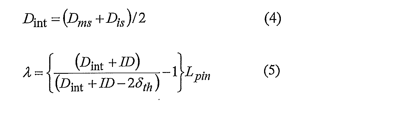
- the outer diameter D int [mm] of the small diameter portion is defined by the following equation (4).
- the small diameter portion extends by ⁇ [mm] in the tube axis direction at the time of fastening due to the interference fit by the interference amount ⁇ th between the first male screw portion of the pin and the first female screw portion of the box.
- the volume V [mm 3 ] before deformation and the volume after deformation V ′ [mm 3 ] in the small diameter portion and the volume and wall thickness are constant before and after deformation, the following equations (6) to (8) holds.
- the inner shoulder surfaces and the intermediate shoulder surfaces start to contact at the same time in the process of fastening the pin and the box.
- ⁇ is larger than ⁇ shld
- the inner shoulder surfaces come into contact with each other after the inner shoulder surfaces come into contact with each other in the fastening process.
- ⁇ is smaller than ⁇ shld
- the inner shoulder surfaces come into contact with each other after the intermediate shoulder surfaces come into contact with each other in the fastening process.
- Equation (9) if ⁇ is positive, the intermediate shoulder surfaces contact each other first, and if ⁇ is negative, the inner shoulder surfaces contact each other first.
- the lower limit value and upper limit value of the difference in tightening rotation speed at which sufficient sealing performance can be exhibited be ⁇ min and ⁇ max , respectively. Then, excellent in order to ensure the sealing performance, after contact with one of the shoulder faces, it is necessary to complete the engagement with delta min or more delta max following tightening speed. That is, the tightening rotation speed difference ⁇ needs to satisfy the following formula (10).
- FIG. 5 is a graph showing the relationship between the tightening rotation speed difference ⁇ expressed by the equation (9) and the intermediate shoulder interference amount ⁇ shld .
- ⁇ shld is in a range indicated by hatching in FIG.
- the present inventors have found preferable values of ⁇ min and ⁇ max and an appropriate range of ⁇ shld , and completed the threaded joint for steel pipes according to the embodiment.
- the threaded joint for steel pipes includes a tubular pin and a tubular box.
- the pin is screwed into the box and the pin and the box are fastened.
- the pin includes a first shoulder surface, a first seal surface, a first male screw portion of a taper screw, a second shoulder surface, a second seal surface, and a second male screw portion of a taper screw in order from the tip side.
- the box includes a first shoulder surface, a first seal surface, a first seal surface, a taper corresponding to each of the first shoulder surface, the first seal surface, the first male screw portion, the second shoulder surface, the second seal surface, and the second male screw portion of the pin.
- a first female thread portion of the screw, a second shoulder surface, a second seal surface, and a second female thread portion of the taper screw are provided.
- the pin includes a nose portion connected to the first seal surface between the first shoulder surface and the first seal surface.
- the pin includes an unthreaded extension connected to the second seal surface between the second shoulder surface and the second seal surface.
- the box includes a recess corresponding to the nose portion of the pin.
- the box includes an unthreaded extension that corresponds to the unthreaded extension of the pin. In the fastened state, the first shoulder surfaces contact each other, the first seal surfaces contact each other, the second seal surfaces contact each other, and a gap is formed between the pin nose and the box recess.
- a gap is formed between the unthreaded extension portion of the pin and the unthreaded extension portion of the box, the first male screw portion and the first female screw portion are fitted, and the second male screw portion and the second female screw portion are fitted.
- L pin is the distance in the tube axis direction from the first shoulder surface to the second shoulder surface in the unfastened pin
- L is the distance in the tube axis direction from the first shoulder surface to the second shoulder surface in the unfastened box.
- P is the thread pitch of the first male thread portion
- ⁇ min is the lower limit value of the tightening rotation speed after the first shoulder surfaces or the second shoulder surfaces contact each other in the fastening process
- ⁇ max is the tightening rotation.
- the upper limit of the number, ⁇ is the amount of elongation at the time of fastening the portion of the pin that is on the tip side of the second shoulder surface.
- the inner diameter of the pin is ID
- the innermost diameter of the second shoulder surface of the pin is D ms
- the outermost diameter of the first shoulder surface of the pin is Dis
- the amount of interference ⁇ th between the first male screw portion and the first female screw portion is ⁇ is expressed using the following equations (4) and (5).
- the intermediate shoulder interference amount ⁇ shld is set so as to satisfy the expressions (2) and (3), the contact timing between the first shoulder surfaces and the contact timing between the second shoulder surfaces greatly deviate in the fastening process. There is nothing. Therefore, excessive plastic deformation is unlikely to occur on the shoulder surface that has started contact, and excellent sealing performance can be ensured.
- FIG. 6 is a longitudinal sectional view showing the threaded joint for steel pipes according to the embodiment.
- the threaded joint is a coupling-type threaded joint and includes a pin 10 and a box 20.
- FIG. 7 is an enlarged longitudinal sectional view of the vicinity of the tip of the pin 10 in the threaded joint shown in FIG.
- FIG. 8 is an enlarged longitudinal sectional view of the vicinity of the center in the tube axis direction in the threaded joint shown in FIG.
- the distal end side of the pin 10 and the base side of the box 20 may be referred to as in or front, and the base side of the pin 10 and the distal end side of the box 20 may be referred to as outside or rear.
- the pin 10 has a first shoulder surface 11, a nose portion 12, a first seal surface 13, a first male screw portion 14, a second shoulder surface 18, a first threadless extension portion 15a, in order from the distal end side to the base side.
- a second sealing surface 16, a second unthreaded extension 15b, and a second male thread 17 are provided. Both the first seal surface 13 and the second seal surface 16 are tapered. Strictly speaking, each of the first seal surface 13 and the second seal surface 16 has a shape composed of a surface corresponding to the peripheral surface of the truncated cone whose diameter is reduced toward the tip side, or the peripheral surface of the truncated cone, an arc, and the like. And a surface corresponding to the peripheral surface of the rotating body obtained by rotating the curve around the tube axis CL.
- the nose portion 12 has a cylindrical shape and extends in the tube axis direction in connection with the first seal surface 13 closer to the inside.
- the outer peripheral surface of the nose portion 12 may have the same inclination as the taper of the first seal surface 13, or may be a small (loose) or large (steep) taper surface.
- the outer peripheral surface of the nose portion 12 is a tapered surface, strictly speaking, the outer peripheral surface has a shape composed of a surface corresponding to the peripheral surface of the truncated cone whose diameter is reduced toward the tip side, or the peripheral surface of the truncated cone
- the shape is a combination of a surface corresponding to the peripheral surface of the rotating body obtained by rotating a curve such as an arc around the tube axis CL.
- the first shoulder surface 11 is provided at the tip of the nose portion 12.
- the first shoulder surface 11 is an annular surface substantially perpendicular to the tube axis CL. Strictly speaking, the outer peripheral side of the first shoulder surface 11 is slightly tilted toward the tip side of the pin 10.
- the second shoulder surface 18 is disposed between the first male screw portion 14 and the first unthreaded extension portion 15a closer to the inside.
- the second shoulder surface 18 is provided continuously to the first unthreaded extension 15a.
- the second shoulder surface 18 is an annular surface perpendicular to the tube axis CL. But the 2nd shoulder surface 18 may incline slightly the outer peripheral side toward the front end side of the pin 10 like the 1st shoulder surface 11 of the front end of the pin 10.
- the first unthreaded extension 15a extends in the direction of the tube axis in front of the second seal surface 16 on the outside.
- a first male threaded portion 14 is provided on the inner side of the first threadless extension 15a.
- the second unthreaded extension portion 15b extends in the tube axis direction continuously to the rear side of the second seal surface 16 closer to the outside.
- a second male screw portion 17 located on the outside is connected to the second unthreaded extension portion 15b.
- the outer peripheral surface of the first unthreaded extension portion 15a may be a shape that can ensure its rigidity, and may be, for example, a cylindrical surface or a tapered surface that is smaller (loose) than the thread taper of the first male screw portion 14, It may be a curved surface. The same applies to the outer peripheral surface of the second unthreaded extension 15b.
- the box 20 has a first shoulder surface 21, a recess 22, a first seal surface 23, a first female thread portion 24, a second shoulder surface 28, and a first unthreaded extension portion 25a in order from the base side to the distal end side.
- the second seal surface 26, the second unthreaded extension 25b, and the second female thread 27 are provided.
- the extension portion 25b and the second female screw portion 27 are the first shoulder surface 11, the nose portion 12, the first seal surface 13, the first male screw portion 14, the second shoulder surface 18, and the first screwless extension of the pin 10, respectively. It is provided corresponding to the portion 15 a, the second seal surface 16, the second unthreaded extension 15 b, and the second male screw portion 17.
- the first male threaded portion 14 of the pin 10 and the first female threaded portion 24 of the box 20 are tapered screw trapezoidal screws that mesh with each other, and constitute a first threaded portion closer to the inside.
- the second male threaded portion 17 of the pin 10 and the second female threaded portion 27 of the box 20 are also trapezoidal trapezoidal screws that mesh with each other, and constitute a second threaded portion closer to the outside.
- the taper surface of the first screw part is closer to the tube axis CL than the taper surface of the second screw part.
- the second shoulder surfaces 18 and 28 are installed between the first screw portion (the first male screw portion 14 and the first female screw portion 24) and the second screw portion (the second male screw portion 17 and the second female screw portion 27). Because. For this reason, in the pin 10, the outer diameter of the area
- the first male screw portion 14 and the first female screw portion 24 can be screwed to each other, and in the fastened state, the first male screw portion 14 and the first female screw portion 24 are fitted and closely attached to each other, and are in an interference fit state. Similarly, the second male screw portion 17 and the second female screw portion 27 are in an interference fit state.
- first seal surfaces 13 and 23 and the second seal surfaces 16 and 26 come into contact with each other as the pin 10 is screwed in, and are fitted and closely contacted in a fastened state, resulting in an interference fit state. Thereby, each 1st seal surface 13 and 23 and each 2nd seal surface 16 and 26 form the 1st seal part and the 2nd seal part by metal contact, respectively.
- a gap is formed between the nose portion 12 of the pin 10 and the recess 22 of the box 20, and between the first unthreaded extension 15 a of the pin 10 and the first unthreaded extension 25 a of the box 20.
- a gap is also formed between the second unthreaded extension 15b of the pin 10 and the second unthreaded extension 25b of the box 20.
- the first shoulder surfaces 11 and 21 are pressed against each other and come into contact with each other.
- the pressing contact between the first shoulder surfaces 11 and 21 mainly applies a tightening axial force to the load surface of the first male screw portion 14 of the pin 10.
- the second shoulder surfaces 18 and 28 may be in contact with each other in the fastening state, but may not be in contact with each other even after the fastening is completed, and may face each other with a gap.
- a tightening axial force is mainly applied to the load surface of the second male screw portion 17 of the pin 10.
- FIG. 9 is a diagram showing a simplified vertical cross section of the pin 10 and the box 20 in an unfastened state.
- the distance in the tube axis direction between the first shoulder surface 11 and the second shoulder surface 18 of the pin 10 is L pin [mm].
- the distance in the tube axis direction between the first shoulder surface 21 and the second shoulder surface 28 in the box 20 is L box [mm].
- the first shoulder surfaces 11 and 21 and the second shoulder surfaces 18 and 28 are annular surfaces that intersect the tube axis direction.
- the first shoulder surfaces 11 and 21 and the second shoulder surfaces 18 and 28 may be perpendicular to the tube axis CL, or may be tilted with respect to the surface perpendicular to the tube axis CL.
- L pin in cross-section of the pin 10 in the disengaged state, which is cut along a plane through the tube axis CL, from the innermost end of the first shoulder surface 11, the tube axis direction to the innermost end of the second shoulder surface 18 Distance.
- L box is the direction of the tube axis from the innermost end of the first shoulder surface 21 to the innermost end of the second shoulder surface 28 in the cross section of the unfastened box 20 cut by a plane passing through the tube axis CL. Distance.
- the intermediate shoulder interference amount ⁇ shld [mm] is defined using L pin and L box .
- ⁇ shld is the amount of interference of the second shoulder surfaces 18 and 20 when deformation due to fastening is not considered.
- the portion of the pin 10 on the tip side of the second shoulder surface 18 extends by ⁇ [mm] by the interference fit of the first screw portion. Therefore, it is necessary to determine the positional relationship between the first shoulder surfaces 11 and 21 and the second shoulder surfaces 18 and 28 in consideration of the elongation amount ⁇ of the pin 10.
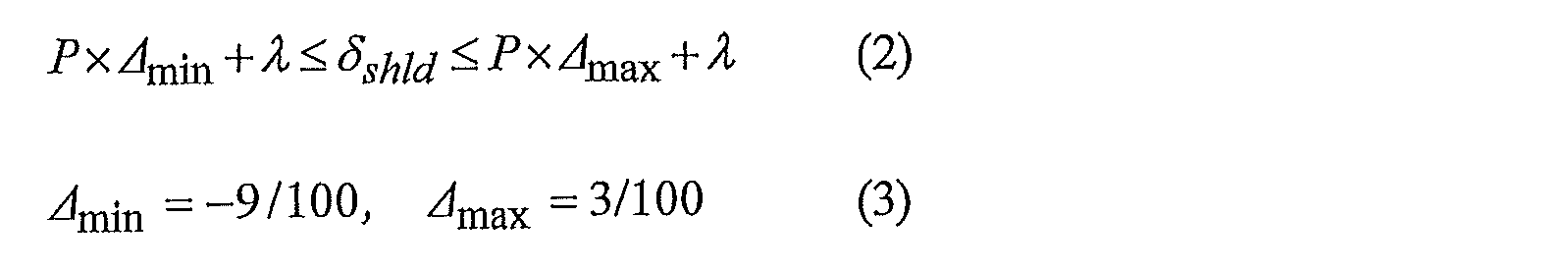
- the intermediate shoulder interference amount ⁇ shld is determined so as to satisfy the following expressions (2) and (3).
- ⁇ min and ⁇ max are differences in tightening rotational speed ⁇ after one of the first shoulder surfaces 11 and 21 and the second shoulder surfaces 18 and 28 come into contact with each other in the fastening process. Are the lower limit value and the upper limit value. If the tightening rotation speed difference ⁇ is ⁇ min or more and ⁇ max or less shown in the above formula (3), sufficient sealing performance can be exhibited.
- the elongation amount ⁇ of the pin 10 is calculated by the following formulas (4) and (5).
- the inner diameter of the pin 10 in the non-fastened state is represented by ID
- the outermost diameter of the first shoulder surface 11 is represented by Dis
- the outermost inner diameter of the second shoulder surface 18 is represented by Dms.
- ⁇ th is the amount of interference of the first threaded portion.
- the interference amount ⁇ th of the first threaded portion is rearward by L pin / 2 from the innermost end of the first shoulder surface 11 in the cross section of the non-fastened pin 10 cut by a plane passing through the tube axis CL.
- the first shoulder surfaces 11 and 21 and the second shoulder surfaces 18 and 28 may be in contact with each other at the same time, or one of them may be in contact first.
- the second shoulder surfaces 18 and 28 having a larger area are brought into contact with or earlier than the first shoulder surfaces 11 and 21.
- the intermediate shoulder interference amount ⁇ shld may be set to be equal to or larger than the elongation amount ⁇ of the pin 10.
- the second shoulder surfaces 18 and 28 may not contact each other, and only the first shoulder surfaces 11 and 21 may contact each other.
- the first shoulder surfaces 11 and 21 are provided at the inner end in the tube axis direction, and the second shoulder surfaces 18 and 28 are provided near the center in the tube axis direction.
- the intermediate shoulder interference amount ⁇ shld is set so as to satisfy the above expressions (2) and (3). According to this configuration, even between the second shoulder surface 18 and 28 is a case in contact first, and then, without compromising the sealing performance, that is the tightening rotational speed of the delta min or more delta max following ranges first
- the shoulder surfaces 11, 21 can be brought into contact with each other to complete the fastening. Therefore, it is possible to prevent a gap from being generated between the tip of the pin 10 and the box 20 while ensuring excellent sealing performance, and to suppress the occurrence of crevice corrosion.
- the intermediate shoulder interference amount [delta] shld is set so as to satisfy the above equation (2) and (3), a first shoulder surface 11, 21 second shoulder surface 18, 28 and appropriate positional relationship Is arranged in. Therefore, in the process of fastening, the contact timing between the first shoulder surfaces 11 and 21 and the contact timing between the second shoulder surfaces 18 and 28 do not greatly deviate. Therefore, since excessive plastic deformation is unlikely to occur on the shoulder surface and the threaded portion that have started contact, excellent sealing performance can be ensured.
- the threaded joint according to the present embodiment includes first shoulder surfaces 11 and 21 and second shoulder surfaces 18 and 28. According to this configuration, it is possible to receive a compressive load in a wider area than a conventional threaded joint in which the shoulder surface is provided only at one place. Therefore, high compression resistance can be ensured.
- the sealing performance against the internal pressure is mainly secured by the close fitting of the first seal surfaces 13 and 23 closer to the inside.
- the sealing performance against the external pressure is mainly ensured by the fitting close contact between the second seal surfaces 16 and 26 close to the outside.
- the pin 10 is provided with a first unthreaded extension 15a that continues to the front of the second seal surface 16 that is closer to the outside, the rigidity of the first unthreaded extension 15a provides the second seal of the pin 10.
- the reduced diameter resistance in the area of the surface 16 is increased. For this reason, even when an external pressure is applied to the threaded joint, the diameter reduction deformation of the pin 10 is suppressed, and a decrease in the contact surface pressure between the second seal surfaces 16 and 26 is suppressed. As a result, the sealing performance against external pressure is improved.
- the box 20 is provided with a first unthreaded extension 25a corresponding to the region of the first unthreaded extension 15a of the pin 10, and between the first unthreaded extensions 15a and 25a in the fastened state.
- a gap is formed. Therefore, the excess dope applied at the time of fastening can be accommodated in the gap. As a result, an inadvertent decrease in the contact surface pressure between the second seal surfaces 16 and 26 due to an increase in dope pressure can be avoided.
- Each of the pin 10 and the box 20 is provided with second unthreaded extensions 15b and 25b connected to the rear of the second seal surface 16 closer to the outside, and between the second unthreaded extensions 15b and 25b.
- a gap is formed in the fastened state. For this reason, a decrease in surface pressure due to a substantial decrease in the amount of interference between the second seal surfaces 16 and 26 due to the interference fitting action of the second screw portion can be suppressed. As a result, the sealing performance against external pressure is improved.
- the pin 10 is provided with a nose portion 12 connected to the first seal surface 13 closer to the inside.
- the box 20 is provided with a recess 22 corresponding to the region of the nose portion 12 of the pin 10.
- a gap is formed between the nose portion 12 and the recess 22 in the fastened state.
- the regions of the first male screw portion 14 and the first seal surface 13 near the inside of the pin 10 are thinned by the installation of the second shoulder surfaces 18 and 28.
- the thinned region is effectively enlarged and deformed. For this reason, the contact surface pressure between the first seal surfaces 13 and 23 is amplified.
- the regions of the second seal surface 16 and the second male screw portion 17 near the outside of the pin 10 are thickened, and the rigidity thereof is relatively high. Therefore, when an external pressure is applied to the threaded joint, the diameter reduction deformation of the region is suppressed, so that the contact surface pressure between the second seal surfaces 16 and 26 can be kept high.
- the cross-sectional area of the steel pipe body in the cross section perpendicular to the tube axis CL is A 0, and the total projected area of each of the first shoulder surface 11 and the second shoulder surface 18 on the plane perpendicular to the tube axis CL is and a 2.
- the area ratio (hereinafter also referred to as “total shoulder area ratio relative to the steel pipe body”)
- a 2 / A 0 is 30% or more. More preferably, A 2 / A 0 is 35% or more.
- a 2 / A 0 substantially depends on the areas of the first shoulder surface 11 and the second shoulder surface 18. When A 2 / A 0 is small, the areas of the first shoulder surface 11 and the second shoulder surface 18 are small.
- the first shoulder surface and the second shoulder surface 18 It cannot withstand that compressive load.
- the first shoulder surface 11 and the nose portion 12 and the first seal surface 13 connected to the first shoulder surface 11 are plastically deformed, and the contact state between the first seal surfaces 13 and 23 becomes unstable.
- the second shoulder surface 18, the first unthreaded extension 15a and the second seal surface 16 connected thereto are plastically deformed, and the contact state between the second seal surfaces 16 and 26 becomes unstable.
- the contact surface pressure between the first seal surfaces 13 and 23 and the contact surface pressure between the second seal surfaces 16 and 26 may be reduced. Therefore, total shoulder area ratio A 2 / A 0 for the steel body is preferably large to some extent.
- the upper limit of the total shoulder area ratio A 2 / A 0 for the steel pipe body is not particularly specified. However, if A 2 / A 0 is too large, the areas of the first shoulder surface 11 and the second shoulder surface 18 are substantially too large, and therefore the outer diameters of the first shoulder surface 11 and the second shoulder surface 18 of the pin 10. Will be too big. As a result, in the box 20, the inner diameters of the regions of the first female screw portion 24 and the first seal surface 23 are increased. In order to ensure the cross-sectional area of the dangerous cross section of the box 20, the outer diameter of the box must be increased. In addition, it is difficult to ensure the engagement length of the first screw portion and the second screw portion. For this reason, considering the practicality, the total shoulder area ratio A 2 / A 0 with respect to the steel pipe body is preferably 60% or less.
- the area ratio between the two hereinafter, also referred to as “first shoulder area ratio with respect to all shoulders”
- a 1 / A 2 is 35% or more. More preferably, A 1 / A 2 is 40% or more.
- a 1 / A 2 is compared with the second shoulder surface 18 and substantially depends on the area of the first shoulder surface 11. If A 1 / A 2 is small, the area of the first shoulder surface 11 is small.
- the first shoulder surface 11 cannot withstand the compressive load.
- the first shoulder surface 11 and the nose portion 12 and the first seal surface 13 connected to the first shoulder surface 11 are plastically deformed, and the contact state between the first seal surfaces 13 and 23 becomes unstable.
- the contact surface pressure between the first seal surfaces 13 and 23 may decrease.
- the first shoulder area ratio A 1 / A 2 with respect to all shoulders is large to some extent.
- the first upper shoulder area rate A 1 / A 2 for all shoulder is not particularly defined. However, if A 1 / A 2 is too large, the area of the first shoulder surface 11 is substantially too large as compared with the second shoulder surface 18, so that the nose portion 12 of the pin 10 that is continuous with the first shoulder surface 11 The wall thickness and the regions of the first male screw portion 14 and the first seal surface 13 are too thick. As a result, when the internal pressure is applied to the threaded joint, the region does not effectively expand and deform, and the amplification effect of the contact surface pressure between the first seal surfaces 13 and 23 cannot be obtained. In this case, the contact surface pressure between the first seal surfaces 13 and 23 may decrease. For this reason, in consideration of practicality, the first shoulder area ratio A 1 / A 2 with respect to all shoulders is preferably 55% or less.
- the minimum outer diameter of the first unthreaded extension 15a is preferably larger than the diameter of the reference tapered surface 19b.
- the reference tapered surface 19b is a tapered surface 19b having an outer diameter that is twice as large as the screw height of the second male screw portion 17 than the taper extension surface 19a of the bottom surface of the thread valley of the second male screw portion 17. The reason is as follows.
- the outer diameter of the first unthreaded extension 15a substantially depends on the thickness of the first unthreaded extension 15a. If the outer diameter of the first unthreaded extension 15a is small, the thickness of the first unthreaded extension 15a is thin.
- the second due to the rigidity of the first unthreaded extension 15a.
- the diameter reduction resistance in the region of the seal surface 16 becomes insufficient.
- the contact surface pressure between the second seal surfaces 16 and 26 may decrease.
- the outer diameter of the 1st threadless extension part 15a is large to some extent.
- the upper limit of the outer diameter of the first unthreaded extension 15a is not specified. However, the outer diameter of the first unthreaded extension 15a needs to be a size that does not interfere with the second seal surface 26 of the box 20 during fastening.
- the length along the tube axis of the first threadless extension 15 a is at least one times the thread pitch of the second male thread 17 as measured from the front end of the second seal surface 16. Is preferred. If the length of the first unthreaded extension portion 15a is short, the second seal surfaces 16, 26 are applied when an external pressure is applied to the threaded joint, for the same reason as when the first unthreaded extension portion 15a is thin. This is because the contact pressure between them may be reduced.
- the upper limit of the length of the first unthreaded extension 15a is not specified. However, if the length of the first unthreaded extension 15a is too long, the overall length of the joint becomes long, and the manufacturing cost increases due to an increase in processing time and material costs. Further, when the length of the first unthreaded extension portion 15a exceeds a certain length, the effect of improving the sealing performance is almost saturated. For this reason, in consideration of practicality, it is preferable that the length of the first unthreaded extension portion 15 a is 5 times or less the screw pitch of the second male screw portion 17.
- the length along the tube axis of the second unthreaded extension 15 b is one or more times the thread pitch of the second male threaded portion 17 as measured from the end on the rear end side of the second seal surface 16. It is preferable. If the length of the second threadless extension 15b is short, the substantial amount of interference between the second seal surfaces 16 and 26 due to the interference fit action of the second screw portions decreases, and the second seal surfaces 16 and 26 are in contact with each other. This is because the contact surface pressure may decrease.
- the upper limit of the length of the second unthreaded extension 15b is not specified. However, if the length of the second unthreaded extension 15b is too long, the total length of the joint becomes long, and the manufacturing cost increases due to an increase in processing time and material costs. Further, when the length of the second unthreaded extension portion 15b exceeds a certain length, the effect of improving the sealing performance is almost saturated. For this reason, in consideration of practicality, it is preferable that the length of the second unthreaded extension portion 15 b is 5 times or less the screw pitch of the second male screw portion 17.
- the length along the tube axis CL of the nose portion 12 is preferably 5 mm or more. The reason is as follows. If the length of the nose portion 12 is short, when an excessive tensile load is applied to the threaded joint, the elastic restoring force of the first seal surface 13 by the nose portion 12 becomes insufficient. In this case, the contact surface pressure between the first seal surfaces 13 and 23 may decrease. For this reason, the length of the nose portion 12 is preferably long to some extent.
- the upper limit of the length of the nose part 12 is not specified. However, if the length of the nose portion 12 is too long, the total length of the joint becomes long, and the manufacturing cost increases due to an increase in processing time and material costs. Further, when the length of the nose portion 12 exceeds a certain length, the effect of improving the sealing performance is almost saturated. For this reason, in consideration of practicality, the length of the nose portion 12 is preferably 5 times or less the screw pitch of the first male screw portion 14.
- the present disclosure is not limited to the above-described embodiment, and various modifications can be made without departing from the spirit of the present disclosure.
- a measure may be added for relaxing the fitting close contact of the first threaded portion closer to the inside to a region close to the first seal portion.
- region of the 1st seal surface 13 near the inside of the pin 10 carries out diameter expansion deformation more effectively, and the contact surface pressure of the 1st seal surfaces 13 and 23 is amplified more.
- the thread height of the first female thread portion 24 of the box 20 is a cylindrical surface parallel to the tube axis CL, and the thread height is made lower than the regular thread height.
- a gap is provided between the screw thread top surface of the first female screw portion 24 and the screw valley bottom surface of the first male screw portion 14.
- the length of the incomplete thread region is 3 to 9 times (about 15 to 45 mm) the thread pitch of the first female thread portion 24.
- threaded joint of the above embodiment can be applied to both the integral type and the coupling type.
- ⁇ Test conditions Finite element analysis was performed on a plurality of specimens having different intermediate shoulder interference amounts ⁇ shld to compare the differences in performance.
- Each specimen is a coupling type threaded joint having the basic structure shown in FIGS. Common test conditions are shown below.
- the material is an elastic-plastic material with isotropic hardening
- the elastic modulus is 210 [GPa]
- a model of each specimen was used.
- the difference between the contact timing between the inner shoulder surfaces (11, 21) and the contact timing between the intermediate shoulder surfaces (18, 28) was evaluated based on the following four levels. Excellent: The intermediate shoulder surfaces contact each other in the order of the inner shoulder surfaces, and the absolute value of the tightening rotation speed difference ⁇ is 3 [ ⁇ 1/100 turn] or less. Good: The inner shoulder surfaces contact each other in the order of the intermediate shoulder surfaces, and the absolute value of the tightening rotation speed difference ⁇ is 3 [ ⁇ 1/100 turn] or less.
- -Possible The inner shoulder surfaces come into contact with each other first, and the absolute value of the tightening rotational speed difference ⁇ is larger than 3 [ ⁇ 1/100 turn].
- -Impossibility The intermediate shoulder surfaces come into contact with each other first, and the absolute value of the tightening rotation speed difference ⁇ is larger than 3 [ ⁇ 1/100 turn].
- the sealing performance against external pressure and internal pressure includes the contact force per unit length in the circumferential direction of the first seal portion (13, 23) in the internal pressure cycle (first and second quadrants) of the load history, and the external pressure cycle of the load history, respectively. It evaluated by comparing the contact force per unit length of the 2nd seal
- the contact forces of the first seal part and the second seal part are both 0.8 or more, and at least one is less than 0.9.
- -Possible Both the contact forces of the first seal part and the second seal part are 0.7 or more, and at least one is less than 0.8.
- -Impossible One of the contact forces of the first seal part and the second seal part is less than 0.7.
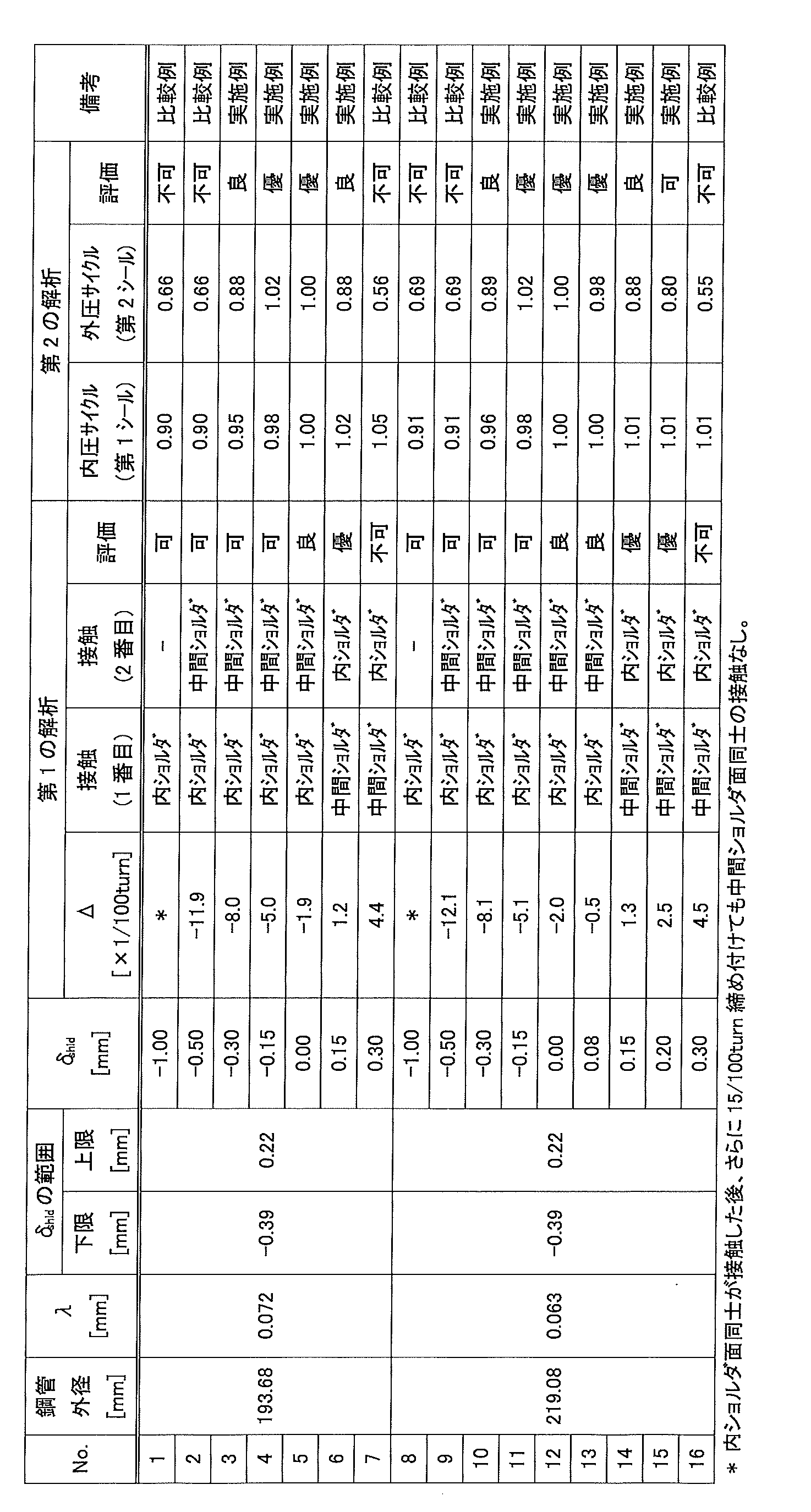
- Table 1 summarizes the test conditions and evaluation of each specimen.
- Table 1 shows the intermediate shoulder interference amount ⁇ shld calculated for each specimen based on the above equation (1).
- ⁇ is 3/100 turns or less in absolute value. Therefore, in normal fastening, both the inner shoulder surfaces and the intermediate shoulder surfaces can be reliably brought into contact with each other, and high compression resistance can be ensured. Furthermore, since the middle shoulder surfaces having a large area come into contact with each other first, it is particularly preferable from the viewpoint of suppressing plastic deformation.
Landscapes
- Engineering & Computer Science (AREA)
- General Engineering & Computer Science (AREA)
- Mechanical Engineering (AREA)
- Geology (AREA)
- Life Sciences & Earth Sciences (AREA)
- Mining & Mineral Resources (AREA)
- Environmental & Geological Engineering (AREA)
- Fluid Mechanics (AREA)
- General Life Sciences & Earth Sciences (AREA)
- Geochemistry & Mineralogy (AREA)
- Physics & Mathematics (AREA)
- Non-Disconnectible Joints And Screw-Threaded Joints (AREA)
- Joints With Pressure Members (AREA)
Abstract
Description


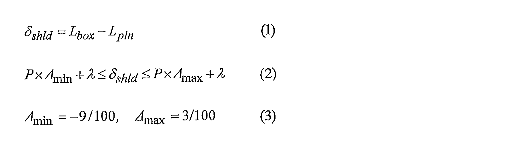
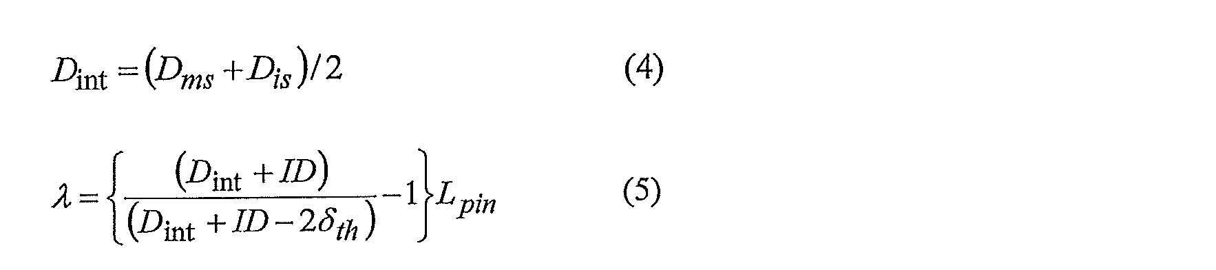
図6は、実施形態に係る鋼管用ねじ継手を示す縦断面図である。当該ねじ継手は、カップリング型のねじ継手であり、ピン10とボックス20とから構成される。図7は、図6に示すねじ継手において、ピン10の先端部付近を拡大した縦断面図である。図8は、図6に示すねじ継手において、管軸方向の中央付近を拡大した縦断面図である。以下、管軸方向において、ピン10の先端側及びボックス20の基部側を内又は前、ピン10の基部側及びボックス20の先端側を外又は後と称する場合がある。


本実施形態に係るねじ継手では、管軸方向の内端に第1ショルダ面11、21が設けられるともに、管軸方向の中央付近に第2ショルダ面18、28が設けられている。本実施形態では、上述の式(2)及び(3)を満たすように中間ショルダ干渉量δshldが設定されている。この構成によれば、第2ショルダ面18、28同士が先に接触した場合であっても、その後、密封性能を低下させない範囲、つまりΔmin以上Δmax以下の範囲の締め付け回転数で第1ショルダ面11、21同士を接触させ、締結を完了することができる。よって、優れた密封性能を確保しつつ、ピン10の先端とボックス20との間にすき間が生じるのを防止することができ、すき間腐食の発生を抑制することができる。
中間ショルダ干渉量δshldが異なる複数の供試体について、有限要素解析を実施して性能の差を比較した。各供試体は、図6~図8に示す基本構造を有するカップリング型のねじ継手である。共通の試験条件を以下に示す。
(1)鋼管の寸法
7-5/8[inch]×1.06[inch](外径193.68[mm]、肉厚27.0[mm])、又は8-5/8[inch]×1.15[inch](外径219.1[mm]、肉厚29.2[mm]]
(2)鋼管のグレード
API規格のP110(公称降伏応力が110[ksi]の炭素鋼)
(3)ねじの寸法(全てのねじで共通)
ねじピッチ:5.08[mm]、荷重面のフランク角:-3°、挿入面のフランク角:10°、挿入面すき間:0.15[mm]
[第1の解析]
第1の解析として、各供試体に対してねじの締め付けの解析を行った。第1の解析では、一方のショルダ面同士が接触した後、他方のショルダ面同士が接触するまで締め付けを行った。ただし、一方のショルダ面同士が接触した後、15/100ターン締め付けても他方のショルダ面同士が接触しなかった場合は、その時点で締め付けを終了した。
・優:中間ショルダ面同士、内ショルダ面同士の順で接触し、締め付け回転数差Δの絶対値が3[×1/100turn]以下である。
・良:内ショルダ面同士、中間ショルダ面同士の順で接触し、締め付け回転数差Δの絶対値が3[×1/100turn]以下である。
・可:内ショルダ面同士が先に接触し、締め付け回転数差Δの絶対値が3[×1/100turn]よりも大きい。
・不可:中間ショルダ面同士が先に接触し、締め付け回転数差Δの絶対値が3[×1/100turn]よりも大きい。
第2の解析では、各供試体について、ISO13679のシリーズA試験を模擬した荷重履歴を締結状態のモデルに負荷した。第2の解析では、内ショルダ面同士及び中間ショルダ面同士のいずれか一方が接触した後、さらに3/100ターン締め付けた時点で締結完了とした。
・優:第1シール部及び第2シール部の接触力がともに0.9以上である。
・良:第1シール部及び第2シール部の接触力がともに0.8以上であり、少なくとも一方が0.9未満である。
・可:第1シール部及び第2シール部の接触力がともに0.7以上であり、少なくとも一方が0.8未満である。
・不可:第1シール部及び第2シール部の接触力のいずれかが0.7未満である。
[第1の解析]
No.3~5、10~13の供試体では、まず内ショルダ面同士が接触するため、ピンの先端とボックスとの間にすき間は生じない。また、δshldが下限以上且つ上限以下であるため、締め付け回転数差Δの絶対値が比較的小さい。つまり、内ショルダ面同士が接触した後、中間ショルダ面同士が接触するまでの締め付け回転数が少ないため、各内ショルダ面の塑性変形が生じにくい。
No.5、6、12~15の供試体では、δshldが下限以上且つ上限以下であって、Δが絶対値で3/100ターン以下であるため、一方のショルダ面同士が接触した後、内ショルダ面同士及び中間ショルダ面同士の双方が接触した。No.5、6、12~15の供試体では、外圧及び内圧に対する密封性能がともに良好であった。
Claims (1)
- 管状のピンと、管状のボックスとから構成され、前記ピンが前記ボックスにねじ込まれて前記ピンと前記ボックスとが締結される鋼管用ねじ継手であって、
前記ピンは、先端側から順に、第1ショルダ面、第1シール面、テーパねじの第1雄ねじ部、第2ショルダ面、第2シール面及びテーパねじの第2雄ねじ部を備え、
前記ボックスは、前記ピンの前記第1ショルダ面、前記第1シール面、前記第1雄ねじ部、前記第2ショルダ面、前記第2シール面及び前記第2雄ねじ部のそれぞれに対応する第1ショルダ面、第1シール面、テーパねじの第1雌ねじ部、第2ショルダ面、第2シール面及びテーパねじの第2雌ねじ部を備え、さらに、
前記ピンは、前記第1ショルダ面と前記第1シール面との間に前記第1シール面に連なるノーズ部を備えるとともに、前記第2ショルダ面と前記第2シール面との間に前記第2シール面に連なるねじ無し延長部を備え、
前記ボックスは、前記ピンの前記ノーズ部に対応する凹部を備えるとともに、前記ピンの前記ねじ無し延長部に対応するねじ無し延長部を備えており、
締結状態において、前記第1ショルダ面同士が互いに接触し、前記第1シール面同士が互いに接触し、前記第2シール面同士が互いに接触し、前記ピンの前記ノーズ部と前記ボックスの前記凹部との間に隙間が形成され、前記ピンの前記ねじ無し延長部と前記ボックスの前記ねじ無し延長部との間に隙間が形成され、前記第1雄ねじ部と前記第1雌ねじ部とが嵌まり合い、前記第2雄ねじ部と前記第2雌ねじ部とが嵌まり合い、
非締結状態の前記ピンにおいて前記第1ショルダ面から前記第2ショルダ面までの管軸方向の距離をLpin、非締結状態の前記ボックスにおいて前記第1ショルダ面から前記第2ショルダ面までの管軸方向の距離をLboxとして、前記ピンの前記第2ショルダ面と前記ボックスの前記第2ショルダ面との干渉量δshldを以下の式(1)で定義したとき、以下の式(2)及び(3)を満たす、鋼管用ねじ継手。

ここで、Pは、前記第1雄ねじ部のねじピッチ、Δminは、締結過程において前記第1ショルダ面同士又は前記第2ショルダ面同士が接触した後の締め付け回転数の下限値、Δmaxは、前記締め付け回転数の上限値、λは、前記ピンのうち前記第2ショルダ面よりも先端側の部分の締結時における伸び量であり、
前記ピンの内径をID、前記ピンの前記第2ショルダ面の最内径をDms、前記ピンの前記第1ショルダ面の最外径をDisとし、前記第1雄ねじ部と前記第1雌ねじ部との干渉量δthとしたとき、λは、以下の式(4)及び(5)を用いて表わされる。
Priority Applications (12)
| Application Number | Priority Date | Filing Date | Title |
|---|---|---|---|
| UAA201806680A UA119127C2 (uk) | 2015-12-15 | 2016-02-11 | Нарізне з'єднання для сталевої труби |
| CA3006937A CA3006937C (en) | 2015-12-15 | 2016-11-02 | Threaded joint for steel pipe |
| CN201680069492.7A CN108291672B (zh) | 2015-12-15 | 2016-11-02 | 钢管用螺纹接头 |
| PL16875267T PL3392543T3 (pl) | 2015-12-15 | 2016-11-02 | Połączenie gwintowe dla rur stalowych |
| EP16875267.3A EP3392543B1 (en) | 2015-12-15 | 2016-11-02 | Threaded joint for steel pipe |
| EA201891174A EA033731B1 (ru) | 2015-12-15 | 2016-11-02 | Резьбовое соединение для стальной трубы |
| AU2016373923A AU2016373923B2 (en) | 2015-12-15 | 2016-11-02 | Threaded joint for steel pipe |
| MYPI2018700937A MY193662A (en) | 2015-12-15 | 2016-11-02 | Threaded joint for steel pipe |
| MX2018003304A MX2018003304A (es) | 2015-12-15 | 2016-11-02 | Union roscada para tubo de acero. |
| US16/060,770 US10495241B2 (en) | 2015-12-15 | 2016-11-02 | Threaded joint for steel pipe |
| JP2017556406A JP6512586B2 (ja) | 2015-12-15 | 2016-11-02 | 鋼管用ねじ継手 |
| BR112018004456-3A BR112018004456B1 (pt) | 2015-12-15 | 2016-11-02 | Junta roscada para tubulação de aço |
Applications Claiming Priority (2)
| Application Number | Priority Date | Filing Date | Title |
|---|---|---|---|
| JP2015244620 | 2015-12-15 | ||
| JP2015-244620 | 2015-12-15 |
Publications (1)
| Publication Number | Publication Date |
|---|---|
| WO2017104282A1 true WO2017104282A1 (ja) | 2017-06-22 |
Family
ID=59056004
Family Applications (1)
| Application Number | Title | Priority Date | Filing Date |
|---|---|---|---|
| PCT/JP2016/082567 WO2017104282A1 (ja) | 2015-12-15 | 2016-11-02 | 鋼管用ねじ継手 |
Country Status (14)
| Country | Link |
|---|---|
| US (1) | US10495241B2 (ja) |
| EP (1) | EP3392543B1 (ja) |
| JP (1) | JP6512586B2 (ja) |
| CN (1) | CN108291672B (ja) |
| AR (1) | AR107034A1 (ja) |
| AU (1) | AU2016373923B2 (ja) |
| BR (1) | BR112018004456B1 (ja) |
| CA (1) | CA3006937C (ja) |
| EA (1) | EA033731B1 (ja) |
| MX (1) | MX2018003304A (ja) |
| MY (1) | MY193662A (ja) |
| PL (1) | PL3392543T3 (ja) |
| UA (1) | UA119127C2 (ja) |
| WO (1) | WO2017104282A1 (ja) |
Cited By (6)
| Publication number | Priority date | Publication date | Assignee | Title |
|---|---|---|---|---|
| WO2019093163A1 (ja) | 2017-11-09 | 2019-05-16 | 日本製鉄株式会社 | 鋼管用ねじ継手 |
| WO2020137917A1 (ja) | 2018-12-25 | 2020-07-02 | 日本製鉄株式会社 | 鋼管用ねじ継手 |
| WO2021029370A1 (ja) | 2019-08-09 | 2021-02-18 | 日本製鉄株式会社 | 鋼管用ねじ継手 |
| WO2021145163A1 (ja) * | 2020-01-17 | 2021-07-22 | 日本製鉄株式会社 | 管用ねじ継手 |
| JPWO2021145162A1 (ja) * | 2020-01-17 | 2021-07-22 | ||
| WO2021145161A1 (ja) * | 2020-01-17 | 2021-07-22 | 日本製鉄株式会社 | 管用ねじ継手 |
Families Citing this family (3)
| Publication number | Priority date | Publication date | Assignee | Title |
|---|---|---|---|---|
| WO2020075366A1 (ja) * | 2018-10-11 | 2020-04-16 | 日本製鉄株式会社 | 鋼管用ねじ継手 |
| CN109404586A (zh) * | 2018-12-31 | 2019-03-01 | 桂林电子科技大学 | 一种基于人机工程学改良的带气密及液密性螺纹的水龙头 |
| US20240052710A1 (en) * | 2022-08-10 | 2024-02-15 | Saudi Arabian Oil Company | High torque threaded connections with external upset and multiple seals |
Citations (5)
| Publication number | Priority date | Publication date | Assignee | Title |
|---|---|---|---|---|
| US4696498A (en) * | 1986-10-29 | 1987-09-29 | Quanex Corporation | Tubular connection |
| JPH09126366A (ja) * | 1995-10-03 | 1997-05-13 | Vallourec Oil & Gas | 管のねじ継手 |
| WO2014045973A1 (ja) * | 2012-09-21 | 2014-03-27 | 新日鐵住金株式会社 | 鋼管用ねじ継手 |
| JP2015534614A (ja) * | 2012-09-21 | 2015-12-03 | ヴァルレック オイル アンド ガスフランス | 管状ねじ接続 |
| WO2015194160A1 (ja) * | 2014-06-20 | 2015-12-23 | 新日鐵住金株式会社 | 鋼管用ねじ継手 |
Family Cites Families (12)
| Publication number | Priority date | Publication date | Assignee | Title |
|---|---|---|---|---|
| IT1044052B (it) * | 1974-09-27 | 1980-03-20 | Mannesmann Roehren Werke Ag | Giunto filettato per tubi petroliferi |
| US4192533A (en) * | 1976-04-22 | 1980-03-11 | Hydril Company | Dovetail connection for pin and box joints |
| US4085951A (en) * | 1976-10-28 | 1978-04-25 | Wonder Products Company | Hydril-type connector |
| US4253687A (en) * | 1979-06-11 | 1981-03-03 | Whiting Oilfield Rental, Inc. | Pipe connection |
| US4662659A (en) * | 1983-01-17 | 1987-05-05 | Hydril Company | Tubular joint with trapped mid-joint metal-to-metal seal having unequal tapers |
| IT1318179B1 (it) * | 2000-07-17 | 2003-07-23 | Dalmine Spa | Giunzione filettata integrale per tubi. |
| FR2855587B1 (fr) * | 2003-05-30 | 2006-12-29 | Vallourec Mannesmann Oil & Gas | Joint filete tubulaire a serrage axial progressif des filets |
| JP2007205361A (ja) * | 2004-08-27 | 2007-08-16 | Sumitomo Metal Ind Ltd | 鋼管用ねじ継手 |
| ITRM20050069A1 (it) * | 2005-02-17 | 2006-08-18 | Tenaris Connections Ag | Giunzione filettata per tubi provvista di tenuta. |
| FR2956466B1 (fr) * | 2010-02-17 | 2012-06-08 | Vallourec Mannesmann Oil & Gas | Joint filete expansible et procede de realisation |
| CN202788652U (zh) * | 2012-06-28 | 2013-03-13 | 中国石油天然气集团公司 | 螺纹接头的密封结构 |
| US20150069752A1 (en) * | 2013-09-06 | 2015-03-12 | Baker Hughes Incorporated | Modular Tubing Seal Bore System |
-
2016
- 2016-02-11 UA UAA201806680A patent/UA119127C2/uk unknown
- 2016-11-02 MX MX2018003304A patent/MX2018003304A/es unknown
- 2016-11-02 EA EA201891174A patent/EA033731B1/ru not_active IP Right Cessation
- 2016-11-02 PL PL16875267T patent/PL3392543T3/pl unknown
- 2016-11-02 CA CA3006937A patent/CA3006937C/en active Active
- 2016-11-02 WO PCT/JP2016/082567 patent/WO2017104282A1/ja active Application Filing
- 2016-11-02 US US16/060,770 patent/US10495241B2/en active Active
- 2016-11-02 JP JP2017556406A patent/JP6512586B2/ja active Active
- 2016-11-02 CN CN201680069492.7A patent/CN108291672B/zh active Active
- 2016-11-02 EP EP16875267.3A patent/EP3392543B1/en active Active
- 2016-11-02 AU AU2016373923A patent/AU2016373923B2/en active Active
- 2016-11-02 MY MYPI2018700937A patent/MY193662A/en unknown
- 2016-11-02 BR BR112018004456-3A patent/BR112018004456B1/pt active IP Right Grant
- 2016-12-12 AR ARP160103780A patent/AR107034A1/es active IP Right Grant
Patent Citations (5)
| Publication number | Priority date | Publication date | Assignee | Title |
|---|---|---|---|---|
| US4696498A (en) * | 1986-10-29 | 1987-09-29 | Quanex Corporation | Tubular connection |
| JPH09126366A (ja) * | 1995-10-03 | 1997-05-13 | Vallourec Oil & Gas | 管のねじ継手 |
| WO2014045973A1 (ja) * | 2012-09-21 | 2014-03-27 | 新日鐵住金株式会社 | 鋼管用ねじ継手 |
| JP2015534614A (ja) * | 2012-09-21 | 2015-12-03 | ヴァルレック オイル アンド ガスフランス | 管状ねじ接続 |
| WO2015194160A1 (ja) * | 2014-06-20 | 2015-12-23 | 新日鐵住金株式会社 | 鋼管用ねじ継手 |
Non-Patent Citations (1)
| Title |
|---|
| See also references of EP3392543A4 * |
Cited By (20)
| Publication number | Priority date | Publication date | Assignee | Title |
|---|---|---|---|---|
| US11300233B2 (en) | 2017-11-09 | 2022-04-12 | Nippon Steel Corporation | Threaded connection for steel pipe |
| EP3708892A4 (en) * | 2017-11-09 | 2020-11-25 | Nippon Steel Corporation | SCREW CONNECTION FOR STEEL PIPES |
| WO2019093163A1 (ja) | 2017-11-09 | 2019-05-16 | 日本製鉄株式会社 | 鋼管用ねじ継手 |
| WO2020137917A1 (ja) | 2018-12-25 | 2020-07-02 | 日本製鉄株式会社 | 鋼管用ねじ継手 |
| US11892106B2 (en) | 2018-12-25 | 2024-02-06 | Nippon Steel Corporation | Threaded connection for steel pipe |
| US11753878B2 (en) | 2019-08-09 | 2023-09-12 | Nippon Steel Corporation | Threaded connection for steel pipe |
| EP4012239A4 (en) * | 2019-08-09 | 2022-08-03 | Nippon Steel Corporation | THREADED COUPLING FOR STEEL PIPE |
| WO2021029370A1 (ja) | 2019-08-09 | 2021-02-18 | 日本製鉄株式会社 | 鋼管用ねじ継手 |
| CN114026309B (zh) * | 2019-08-09 | 2023-06-20 | 日本制铁株式会社 | 钢管用螺纹接头 |
| AU2020327779B2 (en) * | 2019-08-09 | 2023-02-02 | Nippon Steel Corporation | Threaded connection for steel pipe |
| CN114026309A (zh) * | 2019-08-09 | 2022-02-08 | 日本制铁株式会社 | 钢管用螺纹接头 |
| JPWO2021145163A1 (ja) * | 2020-01-17 | 2021-07-22 | ||
| JPWO2021145162A1 (ja) * | 2020-01-17 | 2021-07-22 | ||
| WO2021145161A1 (ja) * | 2020-01-17 | 2021-07-22 | 日本製鉄株式会社 | 管用ねじ継手 |
| WO2021145162A1 (ja) * | 2020-01-17 | 2021-07-22 | 日本製鉄株式会社 | 管用ねじ継手 |
| WO2021145163A1 (ja) * | 2020-01-17 | 2021-07-22 | 日本製鉄株式会社 | 管用ねじ継手 |
| JP7367069B2 (ja) | 2020-01-17 | 2023-10-23 | 日本製鉄株式会社 | 管用ねじ継手 |
| JPWO2021145161A1 (ja) * | 2020-01-17 | 2021-07-22 | ||
| JP7431863B2 (ja) | 2020-01-17 | 2024-02-15 | 日本製鉄株式会社 | 管用ねじ継手 |
| JP7455866B2 (ja) | 2020-01-17 | 2024-03-26 | 日本製鉄株式会社 | 管用ねじ継手 |
Also Published As
| Publication number | Publication date |
|---|---|
| EP3392543A4 (en) | 2019-09-11 |
| UA119127C2 (uk) | 2019-04-25 |
| JP6512586B2 (ja) | 2019-05-15 |
| CN108291672A (zh) | 2018-07-17 |
| EA201891174A1 (ru) | 2018-11-30 |
| MY193662A (en) | 2022-10-24 |
| AU2016373923B2 (en) | 2019-08-29 |
| MX2018003304A (es) | 2018-05-16 |
| EA033731B1 (ru) | 2019-11-20 |
| JPWO2017104282A1 (ja) | 2018-05-24 |
| CA3006937C (en) | 2020-01-07 |
| AU2016373923A1 (en) | 2018-03-08 |
| EP3392543A1 (en) | 2018-10-24 |
| PL3392543T3 (pl) | 2021-11-08 |
| CA3006937A1 (en) | 2017-06-22 |
| US10495241B2 (en) | 2019-12-03 |
| US20180363813A1 (en) | 2018-12-20 |
| EP3392543B1 (en) | 2021-05-19 |
| BR112018004456A2 (ja) | 2018-09-25 |
| CN108291672B (zh) | 2019-08-30 |
| AR107034A1 (es) | 2018-03-14 |
| BR112018004456B1 (pt) | 2022-08-23 |
Similar Documents
| Publication | Publication Date | Title |
|---|---|---|
| WO2017104282A1 (ja) | 鋼管用ねじ継手 | |
| JP6239111B2 (ja) | 鋼管用ねじ継手 | |
| JP6139708B2 (ja) | 鋼管用ねじ継手 | |
| JP6588453B2 (ja) | 鋼管用ねじ継手 | |
| JP6831018B2 (ja) | 鋼管用ねじ継手 | |
| JP6683738B2 (ja) | 鋼管用ねじ継手 | |
| JP7182010B2 (ja) | 鋼管用ねじ継手 | |
| WO2019111803A1 (ja) | 鋼管用ねじ継手 | |
| US20210164593A1 (en) | Threaded connection for steel pipes | |
| OA20943A (en) | Threaded coupling for steel pipe | |
| EA042332B1 (ru) | Резьбовое соединение для стальных труб | |
| OA18698A (en) | Threaded joint for steel pipe |
Legal Events
| Date | Code | Title | Description |
|---|---|---|---|
| 121 | Ep: the epo has been informed by wipo that ep was designated in this application |
Ref document number: 16875267 Country of ref document: EP Kind code of ref document: A1 |
|
| ENP | Entry into the national phase |
Ref document number: 2017556406 Country of ref document: JP Kind code of ref document: A |
|
| ENP | Entry into the national phase |
Ref document number: 2016373923 Country of ref document: AU Date of ref document: 20161102 Kind code of ref document: A |
|
| WWE | Wipo information: entry into national phase |
Ref document number: MX/A/2018/003304 Country of ref document: MX |
|
| REG | Reference to national code |
Ref country code: BR Ref legal event code: B01A Ref document number: 112018004456 Country of ref document: BR |
|
| ENP | Entry into the national phase |
Ref document number: 3006937 Country of ref document: CA |
|
| WWE | Wipo information: entry into national phase |
Ref document number: A201806680 Country of ref document: UA Ref document number: 201891174 Country of ref document: EA |
|
| NENP | Non-entry into the national phase |
Ref country code: DE |
|
| ENP | Entry into the national phase |
Ref document number: 112018004456 Country of ref document: BR Kind code of ref document: A2 Effective date: 20180306 |