EP3904685A1 - Fluid pressure feeding system, power conversion system, power converter and fluid pressure feeding method - Google Patents
Fluid pressure feeding system, power conversion system, power converter and fluid pressure feeding method Download PDFInfo
- Publication number
- EP3904685A1 EP3904685A1 EP18944814.5A EP18944814A EP3904685A1 EP 3904685 A1 EP3904685 A1 EP 3904685A1 EP 18944814 A EP18944814 A EP 18944814A EP 3904685 A1 EP3904685 A1 EP 3904685A1
- Authority
- EP
- European Patent Office
- Prior art keywords
- pumping
- pumping device
- deterioration level
- unit
- power conversion
- Prior art date
- Legal status (The legal status is an assumption and is not a legal conclusion. Google has not performed a legal analysis and makes no representation as to the accuracy of the status listed.)
- Granted
Links
Images




Classifications
-
- F—MECHANICAL ENGINEERING; LIGHTING; HEATING; WEAPONS; BLASTING
- F04—POSITIVE - DISPLACEMENT MACHINES FOR LIQUIDS; PUMPS FOR LIQUIDS OR ELASTIC FLUIDS
- F04B—POSITIVE-DISPLACEMENT MACHINES FOR LIQUIDS; PUMPS
- F04B17/00—Pumps characterised by combination with, or adaptation to, specific driving engines or motors
- F04B17/03—Pumps characterised by combination with, or adaptation to, specific driving engines or motors driven by electric motors
-
- F—MECHANICAL ENGINEERING; LIGHTING; HEATING; WEAPONS; BLASTING
- F04—POSITIVE - DISPLACEMENT MACHINES FOR LIQUIDS; PUMPS FOR LIQUIDS OR ELASTIC FLUIDS
- F04B—POSITIVE-DISPLACEMENT MACHINES FOR LIQUIDS; PUMPS
- F04B23/00—Pumping installations or systems
- F04B23/04—Combinations of two or more pumps
-
- F—MECHANICAL ENGINEERING; LIGHTING; HEATING; WEAPONS; BLASTING
- F04—POSITIVE - DISPLACEMENT MACHINES FOR LIQUIDS; PUMPS FOR LIQUIDS OR ELASTIC FLUIDS
- F04B—POSITIVE-DISPLACEMENT MACHINES FOR LIQUIDS; PUMPS
- F04B49/00—Control, e.g. of pump delivery, or pump pressure of, or safety measures for, machines, pumps, or pumping installations, not otherwise provided for, or of interest apart from, groups F04B1/00 - F04B47/00
- F04B49/007—Installations or systems with two or more pumps or pump cylinders, wherein the flow-path through the stages can be changed, e.g. from series to parallel
-
- F—MECHANICAL ENGINEERING; LIGHTING; HEATING; WEAPONS; BLASTING
- F04—POSITIVE - DISPLACEMENT MACHINES FOR LIQUIDS; PUMPS FOR LIQUIDS OR ELASTIC FLUIDS
- F04B—POSITIVE-DISPLACEMENT MACHINES FOR LIQUIDS; PUMPS
- F04B49/00—Control, e.g. of pump delivery, or pump pressure of, or safety measures for, machines, pumps, or pumping installations, not otherwise provided for, or of interest apart from, groups F04B1/00 - F04B47/00
- F04B49/02—Stopping, starting, unloading or idling control
- F04B49/022—Stopping, starting, unloading or idling control by means of pressure
-
- F—MECHANICAL ENGINEERING; LIGHTING; HEATING; WEAPONS; BLASTING
- F04—POSITIVE - DISPLACEMENT MACHINES FOR LIQUIDS; PUMPS FOR LIQUIDS OR ELASTIC FLUIDS
- F04B—POSITIVE-DISPLACEMENT MACHINES FOR LIQUIDS; PUMPS
- F04B49/00—Control, e.g. of pump delivery, or pump pressure of, or safety measures for, machines, pumps, or pumping installations, not otherwise provided for, or of interest apart from, groups F04B1/00 - F04B47/00
- F04B49/06—Control using electricity
- F04B49/065—Control using electricity and making use of computers
-
- F—MECHANICAL ENGINEERING; LIGHTING; HEATING; WEAPONS; BLASTING
- F04—POSITIVE - DISPLACEMENT MACHINES FOR LIQUIDS; PUMPS FOR LIQUIDS OR ELASTIC FLUIDS
- F04B—POSITIVE-DISPLACEMENT MACHINES FOR LIQUIDS; PUMPS
- F04B49/00—Control, e.g. of pump delivery, or pump pressure of, or safety measures for, machines, pumps, or pumping installations, not otherwise provided for, or of interest apart from, groups F04B1/00 - F04B47/00
- F04B49/20—Control, e.g. of pump delivery, or pump pressure of, or safety measures for, machines, pumps, or pumping installations, not otherwise provided for, or of interest apart from, groups F04B1/00 - F04B47/00 by changing the driving speed
-
- F—MECHANICAL ENGINEERING; LIGHTING; HEATING; WEAPONS; BLASTING
- F04—POSITIVE - DISPLACEMENT MACHINES FOR LIQUIDS; PUMPS FOR LIQUIDS OR ELASTIC FLUIDS
- F04B—POSITIVE-DISPLACEMENT MACHINES FOR LIQUIDS; PUMPS
- F04B51/00—Testing machines, pumps, or pumping installations
-
- F—MECHANICAL ENGINEERING; LIGHTING; HEATING; WEAPONS; BLASTING
- F04—POSITIVE - DISPLACEMENT MACHINES FOR LIQUIDS; PUMPS FOR LIQUIDS OR ELASTIC FLUIDS
- F04B—POSITIVE-DISPLACEMENT MACHINES FOR LIQUIDS; PUMPS
- F04B2201/00—Pump parameters
- F04B2201/12—Parameters of driving or driven means
- F04B2201/1202—Torque on the axis
-
- F—MECHANICAL ENGINEERING; LIGHTING; HEATING; WEAPONS; BLASTING
- F04—POSITIVE - DISPLACEMENT MACHINES FOR LIQUIDS; PUMPS FOR LIQUIDS OR ELASTIC FLUIDS
- F04B—POSITIVE-DISPLACEMENT MACHINES FOR LIQUIDS; PUMPS
- F04B2203/00—Motor parameters
- F04B2203/02—Motor parameters of rotating electric motors
- F04B2203/0201—Current
-
- F—MECHANICAL ENGINEERING; LIGHTING; HEATING; WEAPONS; BLASTING
- F04—POSITIVE - DISPLACEMENT MACHINES FOR LIQUIDS; PUMPS FOR LIQUIDS OR ELASTIC FLUIDS
- F04B—POSITIVE-DISPLACEMENT MACHINES FOR LIQUIDS; PUMPS
- F04B2203/00—Motor parameters
- F04B2203/04—Motor parameters of linear electric motors
- F04B2203/0401—Current
-
- F—MECHANICAL ENGINEERING; LIGHTING; HEATING; WEAPONS; BLASTING
- F04—POSITIVE - DISPLACEMENT MACHINES FOR LIQUIDS; PUMPS FOR LIQUIDS OR ELASTIC FLUIDS
- F04B—POSITIVE-DISPLACEMENT MACHINES FOR LIQUIDS; PUMPS
- F04B2205/00—Fluid parameters
- F04B2205/05—Pressure after the pump outlet
Definitions
- the present disclosure relates to a fluid pumping system, a power conversion system, a power conversion apparatus, and a fluid pumping method.
- Patent Document 1 discloses a process for operating a variable speed feed water pump, including: additionally supplying a first pump when an operation speed of the second pump continues to be an allowable maximum operation speed for a predetermined time or more; and stopping the operation of the second pump when a state in which a discharge amount of the second pump is small continues for a predetermined time or more.
- Patent Document 1 Japanese Unexamined Patent Publication No. Hei 9(1997)-126144
- An object of the present disclosure is to provide a fluid pumping system that is effective in reducing the frequency of maintenance.
- a fluid pumping system includes: pumping devices for pumping fluid; a deterioration level estimation unit configured to estimate a deterioration level of one pumping device based on information about a driving force of the one pumping device; a selection unit configured to select at least one pumping device from the pumping devices based on the deterioration level estimated by the deterioration level estimation unit; and a pumping control unit configured to control the at least one pumping device selected by the selection unit to pump fluid.
- a power conversion system includes: a plurality of power conversion units configured to output a driving current to electrical pumping devices respectively; a deterioration level estimation unit configured to estimate a deterioration level of a pumping device based on a driving current output to the pumping device by one of the power conversion units; a selection unit configured to select at least one pumping device from the pumping devices based on the deterioration level estimated by the deterioration level estimation unit; and a pumping control unit configured to control the power conversion unit to output a driving current to the at least one pumping device selected by the selection unit so that the at least one pumping device pumps fluid.
- a power conversion apparatus includes: a power conversion unit configured to output current to a motor of an electrical machine; a deterioration level estimation unit configured to estimate a deterioration level of the machine based on a current output by the power conversion unit; and a control unit configured to output a driving current from the power conversion unit to the motor to operate the machine when the machine is selected from a plurality of machines based on the deterioration level estimated by the deterioration level estimation unit.
- a fluid pumping method includes: estimating a deterioration level of one pumping device based on information about a driving force of the one pumping device; selecting at least one pumping device from the pumping devices based on the estimated deterioration level controlling the, and selected at least one pumping device to pump fluid.
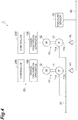
- the fluid pumping system 1 shown in FIG. 1 is a pumping system for increasing the pressure of a water supply line to a water supply consumer facility such as a faucet or a shower head.
- the fluid pumping system 1 includes electrical pumping devices 10, check valves 40, a pressure sensor 30, and a power conversion system 20.
- the pumping device 10 (electrical machine) pumps water (fluid) by electric power.
- the pumping device 10 includes a pump 11 and a motor 12.
- the pump 11 has a suction port 11a connected to the primary side water supply pipe 91 and a discharge port 11b connected to the secondary side water supply pipe 92.
- the "primary side” means the upstream side of the fluid pumping system 1
- the “secondary side” means the downstream side of the fluid pumping system 1.
- the pump 11 incorporates a rotary pumping body such as an impeller or a reciprocating pumping body such as a diaphragm, and pumps water from the suction port 11a to the discharge port 11b by rotation of the rotary pumping body or reciprocation of the reciprocating pumping body. This pumps water from the primary side water supply pipe 91 to the secondary side water supply pipe 92.
- the motor 12 converts electric power into motive power to drive the pump 11.
- the motor 12 is a synchronous motor or an induction motor that converts AC power into rotational torque.
- the object to be pumped by the pumping device 10 may be a liquid other than water.
- the object to be pumped by the pumping device 10 is not necessarily limited to a liquid.
- the pumping device 10 may include a ventilator (for example, a fan or a blower) for pumping gas instead of the pump 11 for liquid pumping.
- a ventilator for example, a fan or a blower
- FIG. 1 two pumping devices 10 are illustrated for convenience, but the number of pumping devices 10 is not limited thereto.
- the fluid pumping system 1 may comprise three or more pumping devices 10.
- the check valves 40 are interposed between the suction ports 11a and the secondary side water supply pipe 92 to prevent backflow of water from the secondary side water supply pipe 92 to the primary side water supply pipe 91.
- the pressure sensor 30 detects the secondary side pressure of the fluid pumping system 1. For example, the pressure sensor 30 is connected to the secondary side water supply pipe 92 on the downstream side of the check valves 40.
- the power conversion system 20 causes at least one of the pumping devices 10 to pump water from the primary side water supply pipe 91 to the secondary side water supply pipe 92 as the pressure detected by the pressure sensor 30 decreases.
- the power conversion system 20 is configured to estimate a deterioration level of any one of the pumping devices 10 based on information about a driving force of the one pumping device 10, select at least one pumping device 10 from the pumping devices 10 based on the estimated deterioration level, and control the selected at least one pumping device 10 to pump water.
- the power conversion system 20 includes a plurality of power conversion apparatuses 100 and a controller 200.
- the plurality of power conversion apparatuses 100 convert power of a power source (e.g., a power system or a battery) into driving power (e.g., AC power) and supply the driving power to the pumping devices 10, respectively.
- a power source e.g., a power system or a battery
- driving power e.g., AC power
- the pumping device 10 to which power is supplied by the power conversion apparatus 100 is referred to as a "corresponding pumping device 10".
- the power conversion apparatus 100 is configured to output a driving current to the motor 12 of the corresponding pumping device 10 to operate the corresponding pumping device 10 when the corresponding pumping device 10 is selected from the pumping devices 10 based on the deterioration level of at least one pumping device 10, and estimate the deterioration level of the corresponding pumping device 10 based on information about a driving force of the corresponding pumping device 10 (e.g., a driving force applied to the pump 11 by the motor 12).
- a driving force of the corresponding pumping device 10 e.g., a driving force applied to the pump 11 by the motor 12.
- the controller 200 selects at least one pumping device 10 from the pumping devices 10 as the pressure detected by the pressure sensor 30 decreases, and outputs a driving current from the power conversion apparatus 100 corresponding to the at least one pumping device 10 to the motor 12 so that water is pumped by the selected at least one pumping device 10.
- the controller 200 selects the at least one pumping device 10 from the pumping devices 10 based on the deterioration level estimated by the at least one power conversion apparatus 100.
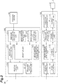
- FIG. 2 is a block diagram illustrating a functional configuration of the power conversion system 20.
- the power conversion apparatus 100 includes a power conversion unit 113, a speed control unit 111, a current control unit 112, a current detection unit 114, a deterioration level estimation unit 115, a pumping control unit 116, a force data acquisition unit 117, and a force data holding unit 118 as functional modules.
- the power conversion unit 113 outputs driving power to the motor 12.
- the power conversion unit 113 outputs an AC voltage having a frequency corresponding to the operation speed of the motor 12 to the motor 12 at a voltage amplitude corresponding to the voltage command.
- the power conversion unit 113 generates the AC voltage by pulse width modulation (PWM).
- PWM pulse width modulation
- the power conversion unit 113 may be an inverter that converts DC power of a DC bus into AC power to generate drive power, or may be a matrix converter that performs bidirectional power conversion between AC power on the AC power supply side and AC power on the motor 12 side.
- the speed control unit 111 causes the speed control unit 111 to output the AC voltage to the motor 12 so that the operation speed of the motor 12 follows the target speed. For example, the speed control unit 111 calculates a current command (torque command) for reducing the deviation between the target speed and the operating speed of the motor 12.
- the current control unit 112 calculates a voltage command for reducing a deviation between the current command calculated by the speed control unit 111 and the driving current being output to the motor 12, and outputs the voltage command to the power conversion unit 113. Accordingly, the power conversion unit 113 outputs, to the motor 12, an AC voltage for causing the operation speed of the motor 12 to follow the target speed.
- the current detection unit 114 detects the driving current output from the power conversion unit 113 to the motor 12 and feeds back the driving current to the current control unit 112.
- the speed control unit 111, the current control unit 112, the power conversion unit 113, and the current detection unit 114 repeat the above-described processing at a predetermined control cycle.
- the force data acquisition unit 117 acquires information (hereinafter, force data) on a driving force of the corresponding pumping device 10 for each control period.
- the information on the driving force (hereinafter, force data) may be any information as long as it is correlated with the driving force to such an extent that the magnitude of the driving force can be grasped based on the information.
- the magnitude of the driving current corresponds to the force data.
- the force data acquisition unit 117 acquires the magnitude of the driving current detected by the current detection unit 114 as force data.
- the force data acquisition unit 117 may acquire the magnitude of the current command calculated by the speed control unit 111 as force data.
- the force data acquisition unit 117 may acquire a detected value of the torque sensor as force data.
- the force data holding unit 118 stores the force data acquired by the force data acquisition unit 117 in time series.
- the deterioration level estimation unit 115 estimates the deterioration level of the corresponding pumping device 10 based on the force data.
- the deterioration level estimation unit 115 calculates an amplitude index value corresponding to the amplitude of the oscillation of the force data as an example of estimating the deterioration level.
- "corresponding” means a correlation in which the amplitude index value increases or decreases in accordance with an increase or decrease in amplitude.
- the amplitude index value may be any value as long as it "corresponds" to the amplitude.
- the amplitude of the oscillation of the force data tends to increase as the deterioration level of the power transmission system from the motor 12 to the pump 11 increases. Therefore, calculating the amplitude index value corresponds to estimating the deterioration level of the pumping device 10.
- Specific examples of the deterioration of the power transmission system include deterioration of a bearing of a torque transmission shaft.
- the deterioration level estimation unit 115 derives the amplitude of the oscillation of the force data as the amplitude index value based on a plurality of force data acquired from a predetermined period before the acquisition time of the force data to the acquisition time.
- the amplitude may be a width from a negative peak to a positive peak, or may be a half of a width from a negative peak to a positive peak.
- the oscillation is an oscillation in a steady operation of the pumping device 10.
- the steady operation means an operation state in which water is filled in the pump 11 and the driving speed of the pump 11 substantially coincides with the target speed. Substantially coincident means that the difference between the driving speed and the target speed is within a negligible error range.
- the deterioration level estimation unit 115 may calculate the difference between the maximum value and the minimum value of the force data within a predetermined period as the amplitude, or may calculate the amplitude by fast Fourier transform (FFT) or the like.
- the deterioration level estimation unit 115 may calculate the amplitude of a predetermined frequency component by FFT, or may calculate an average value, a maximum value, or the like of the amplitude in a frequency component of a predetermined band.
- the deterioration level estimation unit 115 may calculate, as the amplitude index value, the difference between the force data and the trend value of the force data based on the past force data acquired from a predetermined period before the acquisition time of the force data to the acquisition time. For example, the deterioration level estimation unit 115 removes a DC component from the past force data as necessary with respect to the latest force data, and further performs low-pass type filtering to calculate the trend value.
- the deterioration level estimation unit 115 does not necessarily use the latest force data for calculating the trend value, and may calculate the trend value based on only the past force data.
- X[k] may be force data acquired several times (for example, one time) before the latest.
- the pumping control unit 116 controls the power conversion unit 113 to output a driving current to the motor 12 so as to operate the corresponding pumping device 10. For example, when the corresponding pumping device 10 is selected, the pumping control unit 116 causes the speed control unit 111 to start control (control for causing the operating speed of the motor 12 to follow the target speed).
- the controller 200 includes, as functional modules, a deterioration level information acquisition unit 211, a deterioration level information holding unit 212, an operation history holding unit 213, a pressure information acquisition unit 214, a selection unit 215, and a pumping control unit 216.
- the deterioration level information acquisition unit 211 acquires the estimation result of the deterioration level by the deterioration level estimation unit 115 of each power conversion apparatus 100.
- the deterioration level information holding unit 212 stores the estimation result of the deterioration level acquired by the deterioration level information acquisition unit 211 for each power conversion apparatus 100.
- the operation history holding unit 213 stores operation history information of each pumping device 10.
- the operation history information includes, for example, a pumping start time and a pumping stop time of water by the pumping device 10.
- the pressure information acquisition unit 214 acquires information on the secondary side pressure in the pumping devices 10 (for example, a value detected by the pressure sensor 30).
- the selection unit 215 selects at least one pumping device 10 from the pumping devices 10 in response to the secondary side pressure falling below a predetermined lower limit value (hereinafter, pressure lower limit value).
- pressure lower limit value a predetermined lower limit value
- pumping device 10 selected by selection unit 215 is referred to as "pumping device 10 for normal operation”.
- the selection unit 215 selects the pumping device 10 for normal operation based on the deterioration level stored in the deterioration level information holding unit 212. For example, the selection unit 215 selects the pumping device 10 for normal operation such that the operation period of the pumping device 10 having a higher deterioration level is shorter than the operation period of the pumping device 10 having a lower deterioration level. For example, the selection unit 215 selects the pumping device 10 having the lowest deterioration level from the pumping devices 10.
- the selection unit 215 may select the pumping device 10 for normal operation based on a predetermined selection criterion and the deterioration level stored in the deterioration level information holding unit 212. For example, the selection unit 215 may select the pumping device 10 for normal operation based on a first selection criterion based on the deterioration level and a second selection criterion determined separately from the first selection criterion. For example, the first selection criterion is set to select a pumping device 10 having a lower deterioration level over a pumping device 10 having a higher deterioration level.
- the second selection criterion is set to select the pumping device 10 having a shorter cumulative operation period over the pumping device 10 having a longer cumulative operation period.
- the cumulative operation period is substantially correlated with the cumulative operation times. Therefore, selecting the pumping device 10 with a shorter cumulative operation period over the pumping device 10 with a longer cumulative operation period includes selecting the pumping device 10 with fewer cumulative operation times over the pumping device 10 with more cumulative operation times.
- the selection unit 215 derives the priority of each pumping device 10 based on both the first selection criterion and the second selection criterion, and selects the pumping device 10 having the highest priority. For example, the selection unit 215 derives the priority based on a function, a table, or the like defined such that the priority of the pumping device 10 having a lower deterioration level is higher than the priority of the pumping device 10 having a higher deterioration level when there is no difference in the cumulative operation period, and the priority of the pumping device 10 having a short cumulative operation period is higher than the priority of the pumping device 10 having a long cumulative operation period when there is no difference in the deterioration level.
- the selection unit 215 may select the pumping device 10 for normal operation based on the predetermined selection criterion, and select the pumping device 10 for normal operation based on the deterioration level when the deterioration level of any of the pumping devices 10 exceeds a predetermined threshold (hereinafter, referred to as a reference change over threshold). For example, the selection unit 215 may select the pumping device 10 for normal operation based on the second selection criterion when the maximum value of the deterioration level in the pumping devices 10 (hereinafter, the maximum value of the deterioration level) is below the reference change over threshold, and select the pumping device 10 for normal operation based on the first selection criterion when the maximum value of the deterioration level is above the reference change over threshold.
- a predetermined threshold hereinafter, referred to as a reference change over threshold
- the selection unit 215 may change the weight of the first selection criterion with respect to the second selection criterion as the deterioration level increases. For example, the selection unit 215 may change the weight of the first selection criterion with respect to the second selection criterion based on the relationship between the plurality of levels of reference change over thresholds and the maximum value of the deterioration level.
- the selection unit 215 may select the pumping device 10 for normal operation based only on the second selection criterion when the maximum value of the deterioration level is below the minimum reference change over threshold, increase the weight of the first selection criterion for the second selection criterion whenever the maximum value of the deterioration level exceeds the reference change over threshold, and select the pumping device 10 for normal operation based only on the first selection criterion when the maximum value of the deterioration level exceeds the maximum reference change over threshold.
- the selection unit 215 deselects the pumping device 10 for normal operation in response to the secondary side pressure exceeding a predetermined upper limit value (hereinafter, pressure upper limit value).
- the pumping control unit 216 When the pumping device 10 for normal operation is selected, the pumping control unit 216 outputs a driving start command to the power conversion apparatus 100 corresponding to the pumping device 10 for normal operation. Accordingly, the pumping control unit 116 of the power conversion apparatus 100 starts pumping water by the pumping device 10 for normal operation. That is, the pumping control unit 216 controls the pumping device 10 selected by the selection unit 215 to pump water.
- the pumping control unit 216 When the selection of the pumping device 10 for normal operation is released, the pumping control unit 216 outputs a driving stop command to the power conversion apparatus 100 corresponding to the pumping device 10 for normal operation. Accordingly, the pumping control unit 116 of the power conversion apparatus 100 stops the pumping of water by the pumping device 10 for normal operation.
- the controller 200 may be configured to cause at least one pumping device 10 that is not selected by the selection unit 215 to also pump water when a secondary side pressure of the pumping device 10 for normal operation (e.g., a detected value by the pressure sensor 30) is insufficient.
- the controller 200 further includes an additional selection unit 217.
- the additional selection unit 217 selects at least one pumping device 10 not selected by the selection unit 215 from the pumping devices 10 when the secondary side pressure in the pumping device 10 for normal operation is insufficient.
- the pumping device 10 selected by the additional selection unit 217 is referred to as "pumping device 10 for additional operation".
- the additional selection unit 217 selects the pumping device 10 for additional operation when the detected value by the pressure sensor 30 is below a predetermined threshold (hereinafter, referred to as an additional threshold) although the pumping device 10 for normal operation is pumping water.
- the additional threshold may be any value that is greater than or equal to the pressure lower limit value and less than the pressure upper limit value.
- the additional selection unit 217 cancels the selection of the pumping device 10 for additional operation in response to the secondary side pressure exceeding the pressure upper limit value.
- the pumping control unit 216 When the additional selection unit 217 selects the pumping device 10 for additional operation, the pumping control unit 216 outputs a driving start command to the power conversion apparatus 100 corresponding to the pumping device 10 for additional operation. Accordingly, the pumping control unit 116 of the power conversion apparatus 100 starts controlling the pumping device 10 for additional operation to pump water. That is, the pumping control unit 216 controls the pumping device 10 for additional operation to pump water while the pumping control unit 116 for normal operation controls the pumping device 10 for normal operation to pump water. When the selection of the pumping device 10 for additional operation is released, the pumping control unit 216 outputs a driving stop command to the power conversion apparatus 100 corresponding to the pumping device 10 for additional operation. Accordingly, the pumping control unit 116 of the power conversion apparatus 100 stops the pumping of water by the pumping device 10 for additional operation.
- the additional selection unit 217 may be configured to select a pumping device 10 having a higher deterioration level compared to the pumping device 10 for normal operation. For example, when the selection unit 215 does not select the pumping device 10 whose deterioration level exceeds a predetermined threshold, the additional selection unit 217 may select the pumping device 10 whose deterioration level exceeds the threshold. For example, the additional selection unit 217 may also be configured to select a pumping device 10 whose deterioration level exceeds the maximum reference change over threshold.
- the controller 200 may be further configured to notify a user of the deterioration level of the at least one pumping device 10.
- the controller 200 further includes a deterioration notification unit 218.
- the deterioration notification unit 218 notifies the user that the deterioration level of at least one pumping device 10 exceeds a predetermined threshold (hereinafter, referred to as an alert threshold) through a display device.
- the deterioration notification unit 218 notifies the user through the display device that the maximum value of the deterioration level exceeds the alert threshold.
- the display device include a liquid crystal monitor and an alarm lamp.
- the alert threshold may be higher than the reference change over threshold described above.
- the deterioration notification unit 218 may be configured to notify the user of a change in the relationship between the alert threshold and the maximum value of the deterioration level in multiple stages.
- the deterioration notification unit 218 may be configured to notify the user of the increase in the deterioration level each time the deterioration level being increased exceeds the alert threshold.
- the increase in the deterioration level can be notified by a change in the display content on the liquid crystal monitor, a change in the color of the alarm lamp, or the like.
- the deterioration notification unit may be configured to further notify in which pumping device 10 the deterioration level exceeds the alert threshold.
- pumping device 10 the deterioration level exceeds the alert threshold can be notified by displaying identification information of the pumping device 10 exceeding the alert threshold on the liquid crystal monitor, for example.
- pumping device 10 the deterioration level exceeds the alert threshold can be notified by which alarm lamp provided for each pumping device 10 is turned on.
- FIG. 3 is a block diagram illustrating a hardware configuration of the power conversion system 20.
- the power conversion apparatus 100 includes a switching circuit 120, a current sensor 130, and control circuitry 140.
- the switching circuit 120 operates in accordance with a command from the control circuitry 140 (for example, an electric signal from the input/output port 144), and functions as the power conversion unit 113.
- the switching circuit 120 outputs the driving power to the motor 12 by switching on and off a plurality of switching elements in accordance with an electric signal (for example, a gate signal) from the input/output port 144.
- the switching element is, for example, a power metal oxide semiconductor field effect transistor (MOSFET) or an insulated gate bipolar transistor (IGBT).
- MOSFET power metal oxide semiconductor field effect transistor
- IGBT insulated gate bipolar transistor
- the control circuitry 140 includes one or more processors 141, memory 142, storage 143, and an input/output port 144.
- the storage 143 includes a computer-readable storage medium such as a nonvolatile semiconductor memory.
- the storage 143 stores a program for causing the power conversion apparatus 100 to output a driving current to the motor 12 of the corresponding pumping device 10 so as to operate the corresponding pumping device 10 when the corresponding pumping device 10 is selected from the pumping devices 10 based on the deterioration level of the pumping device 12, and to estimate the deterioration level of the corresponding pumping device 10 based on information on the driving force of the corresponding pumping device 10 (e.g., the driving force applied to the pump 11 by the motor 12).
- the storage 143 stores a program for configuring the functional modules of the power conversion apparatus 100.
- the memory 142 temporarily stores a program loaded from the storage medium of the storage 143 and an operation result by the processor 141.
- the processor 141 executes the program in cooperation with the memory 142 to configure each functional module of the power conversion apparatus 100.
- the input/output port 144 has a terminal block of an input power supply, and performs input/output of an electric signal between the switching circuit 120, the current sensor 130, and the controller 200 according to a command from the processor 141.
- the controller 200 includes circuitry 220.
- the circuitry 220 includes one or more processors 221, a memory 222, a storage 223, a display device 224, and an input/output port 225.
- the storage 223 includes a computer-readable storage medium such as a nonvolatile semiconductor memory.
- the storage 223 stores a program for causing the controller 200 to select at least one pumping device 10 from the pumping devices 10 based on the deterioration level estimated by the at least one power conversion apparatus 100, and output a driving current from the power conversion apparatus 100 corresponding to the at least one pumping device 10 to the motor 12 so that water is pumped by the selected at least one pumping device 10.
- the storage 223 stores a program for configuring the functional modules of the controller 200 described above.
- the storage 143 of the power conversion apparatus 100 and the storage 223 of the controller 200 correspond to the storage of the power conversion system 20, and the storage stores a program for causing the power conversion system 20 to estimate the deterioration level of one pumping device 10 based on the information on the driving force of the one pumping device 10, select at least one pumping device 10 from the pumping devices 10 based on the estimated deterioration level, and control the selected at least one pumping device 10 to pump water.
- the memory 222 temporarily stores a program loaded from the storage 223, an operation result by the processor 221, and the like.
- the processor 221 executes the application in cooperation with the memory 222.
- the display device 224 includes, for example, a liquid crystal monitor, an alarm lamp, and the like, and is used for displaying information to the user.
- the input/output port 225 inputs and outputs an electric signal between the pressure sensor 30 and the power conversion apparatus 100 in accordance with a command from the processor 221.
- control circuitry 140 and the circuitry 220 are not necessarily configured by programs.
- at least a part of the functions of the control circuitry 140 and the circuitry 220 may be configured by dedicated logic circuitry or an application specific integrated circuit (ASIC) in which the dedicated logic circuitry is integrated.
- ASIC application specific integrated circuit
- the configuration of the power conversion system 20 described above is merely an example, and can be changed as appropriate.
- one controller 200 is provided for a plurality of power conversion apparatuses 100, but the present configuration is not limited thereto, and a plurality of controllers 200 may be provided for a plurality of power conversion apparatuses 100, respectively (see FIG. 4 ).
- at least one of the plurality of controllers 200 can constitute a functional module of the controller 200 described above.
- the functional module of the controller 200 may be configured by any of the plurality of power conversion apparatuses 100. In this case, the controller 200 may be omitted (see FIG. 5 ).
- the control procedure includes: estimating a deterioration level of one of the pumping devices 10 based on information about a driving force of the one pumping device 10, selecting at least one pumping device 10 from the pumping devices 10 based on the estimated deterioration level, and pumping water by the selected at least one pumping device 10.
- FIG. 6 is a flowchart illustrating a control procedure of the pumping devices 10.
- the power conversion system 20 first executes step S01.
- step S01 the pressure information acquisition unit 214 acquires the detected value by the pressure sensor 30 as the information of the secondary side pressure, and the selection unit 215 checks whether the detected value is below the pressure lower limit value.
- step S01 the power conversion system 20 executes step S01 again. Thereafter, step S01 is repeated until the detected value by the pressure sensor 30 falls below the pressure lower limit value.
- the power conversion system 20 executes steps S02, S03, S04, and S05.
- the selection unit 215 selects the pumping device 10 for normal operation based on the deterioration level stored in the deterioration level information holding unit 212.
- the pumping control unit 216 outputs a driving start command to the power conversion apparatus 100 corresponding to the pumping device 10 for normal operation (hereinafter, power conversion apparatus 100 for normal operation). Accordingly, the pumping control unit 116 of the power conversion apparatus 100 starts the pumping of water by the pumping device 10 for normal operation.
- the force data acquisition unit 117 of the power conversion apparatus 100 for normal operation starts acquiring force data.
- step S05 the pressure information acquisition unit 214 acquires the detected value by the pressure sensor 30 as the information of the secondary side pressure, and the selection unit 215 checks whether the detected value exceeds the pressure upper limit value. If it is determined in step S05 that the detected value does not exceed the pressure upper limit value, the power conversion system 20 executes step S06. In step S06, the additional selection unit 217 checks whether the value detected by the pressure sensor 30 is below the additional threshold.
- step S07 the additional selection unit 217 selects the pumping device 10 for additional operation from the pumping devices 10.
- step S08 the pumping control unit 216 outputs a driving start command to the power conversion apparatus 100 corresponding to the pumping device 10 for additional operation (hereinafter referred to as the power conversion apparatus 100 for additional operation). Accordingly, the pumping control unit 116 of the power conversion apparatus 100 starts pumping water by the pumping device 10 for additional operation.
- step S09 the force data acquisition unit 117 of the power conversion apparatus 100 for additional operation starts acquiring force data. Thereafter, the power conversion system 20 returns the process to step S05.
- step S06 If it is determined in step S06 that the detected value is not below the additional threshold, the power conversion system 20 returns the process to step S05 without executing steps S07, S08, and S09. Thereafter, until the detected value by the pressure sensor 30 exceeds the pressure upper limit value, water pumping by the pumping device 10 for normal operation is continued, and water pumping by the pumping device 10 for additional operation is also continued as necessary.
- step S11 the selection unit 215 cancels the selection of the pumping device 10 for normal operation. Accordingly, the pumping control unit 116 of the power conversion apparatus 100 for normal operation stops the pumping of water by the pumping device 10 for normal operation. If the pumping device 10 for additional operation is selected, the additional selection unit 217 cancels the selection of the pumping device 10 for additional operation. Accordingly, the pumping control unit 116 of the power conversion apparatus 100 for additional operation stops the pumping of water by the pumping device 10 for additional operation.
- step S12 the deterioration level estimation unit 115 of the power conversion apparatus 100 estimates the deterioration level of the pumping device 10 for normal operation based on the force data stored in the force data holding unit 118 of the power conversion apparatus 100 for normal operation.
- the deterioration level estimation unit 115 of the power conversion apparatus 100 for additional operation further estimates the deterioration level of the pumping device 10 for additional operation based on the force data stored in the force data holding unit 118 of the power conversion apparatus 100 for additional operation.
- step S13 the deterioration level information acquisition unit 211 acquires the estimation result of the deterioration level by the deterioration level estimation unit 115 of the power conversion apparatus 100 for the normal operation and the additional operation, and stores the estimation result in the deterioration level information holding unit 212.
- the power conversion system 20 repeats the above processing.
- the deterioration level is estimated once after the operation of the pumping device 10 is stopped, but the timing of estimating the deterioration level is not necessarily limited thereto.
- the estimation of the deterioration level may be repeated during driving.
- the pumping device 10 to be operated may be switched during operation in accordance with an increase in the deterioration level.
- the fluid pumping system 1 includes the pumping devices 10 for pumping water, the deterioration level estimation unit 115 configured to estimate a deterioration level of one pumping device 10 based on information about a driving force of the one pumping device 10, the selection unit 215 configured to select at least one pumping device 10 from the pumping devices 10 based on the deterioration level estimated by the deterioration level estimation unit 115, and the pumping control unit 216 configured to control the at least one pumping device selected by the selection unit 215 to pump water.
- the selection criterion is automatically changed based on the deterioration level, it is possible to preferentially operate the pumping device 10 having a lower deterioration level. This makes it possible to suppress the progress of deterioration of the pumping device 10 having a higher deterioration level. Therefore, it is effective in reducing the frequency of maintenance. In addition, suppressing the progress of deterioration of the pumping device 10 having a higher deterioration level can contribute to improvement of operation efficiency, suppression of vibration, suppression of noise, and the like.
- the selection unit 215 may be further configured to select at least one pumping device 10 based on the predetermined selection criterion and the deterioration level estimated by the deterioration level estimation unit 115. In this case, at a stage where deterioration of any pumping device 10 has not progressed, the pumping devices 10 can be selectively used according to desired conditions by setting selection criterion.
- the selection unit 215 may be further configured to select at least one pumping device 10 based on the deterioration level and selection criterion determined to select the pumping device 10 having a shorter cumulative operation period over the pumping device 10 having a longer cumulative operation period.
- the selection unit 215 may be further configured to select at least one pumping device 10 based on the selection criterion, and to select at least one pumping device 10 based on the deterioration level when a deterioration level of any of the pumping devices 10 exceeds a predetermined threshold.
- the selection unit 215 may be further configured to select at least one pumping device 10 to make an operation period of the pumping device 10 having a higher deterioration level shorter than an operation period of the pumping device 10 having a lower deterioration level. In this case, it is possible to more reliably give priority to the operation of the pumping device 10 having a lower deterioration level.
- the fluid pumping system 1 may further include an additional selection unit 217 configured to select at least one pumping device 10 not selected by the selection unit 215 from the pumping devices 10 when a secondary side pressure of the pumping device 10 selected by the selection unit 215 is insufficient.
- the pumping control unit 216 may be further configured to control the pumping device 10 selected by the additional selection unit 217 to pump water while controlling the pumping device 10 selected by the selection unit 215 to pump water. In this case, by suppressing the progress of deterioration in the pumping device 10 having a higher deterioration level, the usable period of the pumping device 10 as an additional operation object can be extended.
- the additional selection unit 217 may be further configured to select the pumping device 10 having a higher deterioration level than the pumping device 10 selected by the selection unit 215.
- the operation period of the pumping device 10 for additional operation is shorter than the operation period of the pumping device 10 to be operated. Therefore, by allocating the pumping device 10 having a higher deterioration level to the additional operation object, it is possible to effectively use the pumping device 10 while suppressing the progress of deterioration of the pumping device 10 having a higher deterioration level.
- the selection unit 215 may be further configured not to select the pumping device 10 having a deterioration level exceeding the predetermined threshold, and the additional selection unit 217 may be further configured to select the pumping device 10 having the deterioration level exceeding the threshold. In this case, it is possible to more reliably suppress the progress of deterioration of the pumping device 10 having a higher deterioration level and effectively use the pumping device 10 as an additional operation object.
- the fluid pumping system 1 may further comprise a deterioration notification unit 218 configured to notify the user that the deterioration level exceeds a predetermined threshold. In this case, the maintenance timing can be more reliably optimized.
- the deterioration notification unit 218 may be further configured to notify which of the pumping devices 10 the deterioration level exceeds the threshold. In this case, it is effective to improve the efficiency of the maintenance work.
- the pumping device 10 may be electrical, and the deterioration level estimation unit 115 may be further configured to estimate the deterioration level of the pumping device 10 based on the driving current of the pumping device 10.
- the application target of the power conversion system 20 is not necessarily limited to the fluid pumping system.
- the power conversion system 20 can be applied to any machine system as long as the machine system selectively operates a plurality of machines.
Landscapes
- Engineering & Computer Science (AREA)
- Mechanical Engineering (AREA)
- General Engineering & Computer Science (AREA)
- Computer Hardware Design (AREA)
- Control Of Positive-Displacement Pumps (AREA)
- Control Of Non-Positive-Displacement Pumps (AREA)
- Inverter Devices (AREA)
Abstract
Description
- The present disclosure relates to a fluid pumping system, a power conversion system, a power conversion apparatus, and a fluid pumping method.
- Patent Document 1 discloses a process for operating a variable speed feed water pump, including: additionally supplying a first pump when an operation speed of the second pump continues to be an allowable maximum operation speed for a predetermined time or more; and stopping the operation of the second pump when a state in which a discharge amount of the second pump is small continues for a predetermined time or more.
- [Patent Document 1]
Japanese Unexamined Patent Publication No. Hei 9(1997)-126144 - An object of the present disclosure is to provide a fluid pumping system that is effective in reducing the frequency of maintenance.
- A fluid pumping system according to an aspect of the present disclosure includes: pumping devices for pumping fluid; a deterioration level estimation unit configured to estimate a deterioration level of one pumping device based on information about a driving force of the one pumping device; a selection unit configured to select at least one pumping device from the pumping devices based on the deterioration level estimated by the deterioration level estimation unit; and a pumping control unit configured to control the at least one pumping device selected by the selection unit to pump fluid.
- A power conversion system according to another aspect of the present disclosure includes: a plurality of power conversion units configured to output a driving current to electrical pumping devices respectively; a deterioration level estimation unit configured to estimate a deterioration level of a pumping device based on a driving current output to the pumping device by one of the power conversion units; a selection unit configured to select at least one pumping device from the pumping devices based on the deterioration level estimated by the deterioration level estimation unit; and a pumping control unit configured to control the power conversion unit to output a driving current to the at least one pumping device selected by the selection unit so that the at least one pumping device pumps fluid.
- A power conversion apparatus according to still another aspect of the present disclosure includes: a power conversion unit configured to output current to a motor of an electrical machine; a deterioration level estimation unit configured to estimate a deterioration level of the machine based on a current output by the power conversion unit; and a control unit configured to output a driving current from the power conversion unit to the motor to operate the machine when the machine is selected from a plurality of machines based on the deterioration level estimated by the deterioration level estimation unit.
- A fluid pumping method according to still another aspect of the present disclosure includes: estimating a deterioration level of one pumping device based on information about a driving force of the one pumping device; selecting at least one pumping device from the pumping devices based on the estimated deterioration level controlling the, and selected at least one pumping device to pump fluid.
- According to the present disclosure, it is possible to provide a fluid pumping system effective for reducing the frequency of maintenance.
-
-
FIG. 1 is a schematic diagram illustrating a schematic configuration of a fluid pumping system. -
FIG. 2 is a block diagram illustrating a functional configuration of a power conversion system. -
FIG. 3 is a block diagram illustrating a hardware configuration of the power conversion system. -
FIG. 4 is a schematic view illustrating a modification of the fluid pumping system. -
FIG. 5 is a schematic view showing another modification of the fluid pumping system. -
FIG. 6 is a flowchart illustrating a control procedure of pumping devices. - Hereinafter, embodiments will be described in detail with reference to the drawings. In the description, the same element or the element having the same function is denoted by the same reference numeral, and the overlapping description is omitted.
- The fluid pumping system 1 shown in
FIG. 1 is a pumping system for increasing the pressure of a water supply line to a water supply consumer facility such as a faucet or a shower head. The fluid pumping system 1 includeselectrical pumping devices 10,check valves 40, apressure sensor 30, and apower conversion system 20. - The pumping device 10 (electrical machine) pumps water (fluid) by electric power. For example, the
pumping device 10 includes apump 11 and amotor 12. Thepump 11 has asuction port 11a connected to the primary sidewater supply pipe 91 and adischarge port 11b connected to the secondary sidewater supply pipe 92. The "primary side" means the upstream side of the fluid pumping system 1, and the "secondary side" means the downstream side of the fluid pumping system 1. Thepump 11 incorporates a rotary pumping body such as an impeller or a reciprocating pumping body such as a diaphragm, and pumps water from thesuction port 11a to thedischarge port 11b by rotation of the rotary pumping body or reciprocation of the reciprocating pumping body. This pumps water from the primary sidewater supply pipe 91 to the secondary sidewater supply pipe 92. - The
motor 12 converts electric power into motive power to drive thepump 11. For example, themotor 12 is a synchronous motor or an induction motor that converts AC power into rotational torque. The object to be pumped by thepumping device 10 may be a liquid other than water. The object to be pumped by thepumping device 10 is not necessarily limited to a liquid. For example, thepumping device 10 may include a ventilator (for example, a fan or a blower) for pumping gas instead of thepump 11 for liquid pumping. InFIG. 1 , twopumping devices 10 are illustrated for convenience, but the number ofpumping devices 10 is not limited thereto. The fluid pumping system 1 may comprise three ormore pumping devices 10. - The
check valves 40 are interposed between thesuction ports 11a and the secondary sidewater supply pipe 92 to prevent backflow of water from the secondary sidewater supply pipe 92 to the primary sidewater supply pipe 91. Thepressure sensor 30 detects the secondary side pressure of the fluid pumping system 1. For example, thepressure sensor 30 is connected to the secondary sidewater supply pipe 92 on the downstream side of thecheck valves 40. - The
power conversion system 20 causes at least one of thepumping devices 10 to pump water from the primary sidewater supply pipe 91 to the secondary sidewater supply pipe 92 as the pressure detected by thepressure sensor 30 decreases. Thepower conversion system 20 is configured to estimate a deterioration level of any one of thepumping devices 10 based on information about a driving force of the onepumping device 10, select at least onepumping device 10 from thepumping devices 10 based on the estimated deterioration level, and control the selected at least onepumping device 10 to pump water. - For example, the
power conversion system 20 includes a plurality ofpower conversion apparatuses 100 and acontroller 200. The plurality ofpower conversion apparatuses 100 convert power of a power source (e.g., a power system or a battery) into driving power (e.g., AC power) and supply the driving power to thepumping devices 10, respectively. Hereinafter, in the description of eachpower conversion apparatus 100, thepumping device 10 to which power is supplied by thepower conversion apparatus 100 is referred to as a "corresponding pumping device 10". - The
power conversion apparatus 100 is configured to output a driving current to themotor 12 of thecorresponding pumping device 10 to operate thecorresponding pumping device 10 when thecorresponding pumping device 10 is selected from thepumping devices 10 based on the deterioration level of at least onepumping device 10, and estimate the deterioration level of thecorresponding pumping device 10 based on information about a driving force of the corresponding pumping device 10 (e.g., a driving force applied to thepump 11 by the motor 12). - The
controller 200 selects at least onepumping device 10 from thepumping devices 10 as the pressure detected by thepressure sensor 30 decreases, and outputs a driving current from thepower conversion apparatus 100 corresponding to the at least onepumping device 10 to themotor 12 so that water is pumped by the selected at least onepumping device 10. Thecontroller 200 selects the at least onepumping device 10 from thepumping devices 10 based on the deterioration level estimated by the at least onepower conversion apparatus 100. -
FIG. 2 is a block diagram illustrating a functional configuration of thepower conversion system 20. Thepower conversion apparatus 100 includes apower conversion unit 113, aspeed control unit 111, acurrent control unit 112, acurrent detection unit 114, a deteriorationlevel estimation unit 115, apumping control unit 116, a forcedata acquisition unit 117, and a forcedata holding unit 118 as functional modules. - The
power conversion unit 113 outputs driving power to themotor 12. For example, thepower conversion unit 113 outputs an AC voltage having a frequency corresponding to the operation speed of themotor 12 to themotor 12 at a voltage amplitude corresponding to the voltage command. For example, thepower conversion unit 113 generates the AC voltage by pulse width modulation (PWM). Thepower conversion unit 113 may be an inverter that converts DC power of a DC bus into AC power to generate drive power, or may be a matrix converter that performs bidirectional power conversion between AC power on the AC power supply side and AC power on themotor 12 side. - The
speed control unit 111 causes thespeed control unit 111 to output the AC voltage to themotor 12 so that the operation speed of themotor 12 follows the target speed. For example, thespeed control unit 111 calculates a current command (torque command) for reducing the deviation between the target speed and the operating speed of themotor 12. - The
current control unit 112 calculates a voltage command for reducing a deviation between the current command calculated by thespeed control unit 111 and the driving current being output to themotor 12, and outputs the voltage command to thepower conversion unit 113. Accordingly, thepower conversion unit 113 outputs, to themotor 12, an AC voltage for causing the operation speed of themotor 12 to follow the target speed. - The
current detection unit 114 detects the driving current output from thepower conversion unit 113 to themotor 12 and feeds back the driving current to thecurrent control unit 112. Thespeed control unit 111, thecurrent control unit 112, thepower conversion unit 113, and thecurrent detection unit 114 repeat the above-described processing at a predetermined control cycle. - The force
data acquisition unit 117 acquires information (hereinafter, force data) on a driving force of thecorresponding pumping device 10 for each control period. The information on the driving force (hereinafter, force data) may be any information as long as it is correlated with the driving force to such an extent that the magnitude of the driving force can be grasped based on the information. For example, since the magnitude of the driving current is correlated (substantially proportional) to the magnitude of the driving force, the magnitude of the driving current corresponds to the force data. For example, the forcedata acquisition unit 117 acquires the magnitude of the driving current detected by thecurrent detection unit 114 as force data. The forcedata acquisition unit 117 may acquire the magnitude of the current command calculated by thespeed control unit 111 as force data. When thepumping device 10 includes a driving force sensor (e.g., a torque sensor), the forcedata acquisition unit 117 may acquire a detected value of the torque sensor as force data. The forcedata holding unit 118 stores the force data acquired by the forcedata acquisition unit 117 in time series. - The deterioration
level estimation unit 115 estimates the deterioration level of thecorresponding pumping device 10 based on the force data. The deteriorationlevel estimation unit 115 calculates an amplitude index value corresponding to the amplitude of the oscillation of the force data as an example of estimating the deterioration level. Here, "corresponding" means a correlation in which the amplitude index value increases or decreases in accordance with an increase or decrease in amplitude. The amplitude index value may be any value as long as it "corresponds" to the amplitude. - In the
pumping device 10, the amplitude of the oscillation of the force data tends to increase as the deterioration level of the power transmission system from themotor 12 to thepump 11 increases. Therefore, calculating the amplitude index value corresponds to estimating the deterioration level of thepumping device 10. Specific examples of the deterioration of the power transmission system include deterioration of a bearing of a torque transmission shaft. - For example, the deterioration
level estimation unit 115 derives the amplitude of the oscillation of the force data as the amplitude index value based on a plurality of force data acquired from a predetermined period before the acquisition time of the force data to the acquisition time. The amplitude may be a width from a negative peak to a positive peak, or may be a half of a width from a negative peak to a positive peak. The oscillation is an oscillation in a steady operation of thepumping device 10. The steady operation means an operation state in which water is filled in thepump 11 and the driving speed of thepump 11 substantially coincides with the target speed. Substantially coincident means that the difference between the driving speed and the target speed is within a negligible error range. The deteriorationlevel estimation unit 115 may calculate the difference between the maximum value and the minimum value of the force data within a predetermined period as the amplitude, or may calculate the amplitude by fast Fourier transform (FFT) or the like. The deteriorationlevel estimation unit 115 may calculate the amplitude of a predetermined frequency component by FFT, or may calculate an average value, a maximum value, or the like of the amplitude in a frequency component of a predetermined band. - The deterioration
level estimation unit 115 may calculate, as the amplitude index value, the difference between the force data and the trend value of the force data based on the past force data acquired from a predetermined period before the acquisition time of the force data to the acquisition time. For example, the deteriorationlevel estimation unit 115 removes a DC component from the past force data as necessary with respect to the latest force data, and further performs low-pass type filtering to calculate the trend value. - As a specific example of the low-pass type filtering, there is a finite impulse response type filtering. When first order filtering of the finite impulse response method is used, the trend value is derived by the following equation.

- Y: trend value
- X[k]: latest force data
- X[k-1]: previously acquired force data
- A: filter coefficient
- When second order filtering of the finite impulse response method is used, the trend value is derived by the following equation.

- Y: trend value
- X[k]: latest force data
- X[k-1]: previously acquired force data
- X[k-2]: acquired force data two times before
- A and B: filter coefficients.
- The deterioration
level estimation unit 115 does not necessarily use the latest force data for calculating the trend value, and may calculate the trend value based on only the past force data. For example, X[k] may be force data acquired several times (for example, one time) before the latest. - When the
corresponding pumping device 10 is selected from thepumping devices 10 based on the deterioration level estimated by the deteriorationlevel estimation unit 115, thepumping control unit 116 controls thepower conversion unit 113 to output a driving current to themotor 12 so as to operate thecorresponding pumping device 10. For example, when thecorresponding pumping device 10 is selected, thepumping control unit 116 causes thespeed control unit 111 to start control (control for causing the operating speed of themotor 12 to follow the target speed). - The
controller 200 includes, as functional modules, a deterioration levelinformation acquisition unit 211, a deterioration levelinformation holding unit 212, an operationhistory holding unit 213, a pressureinformation acquisition unit 214, aselection unit 215, and apumping control unit 216. The deterioration levelinformation acquisition unit 211 acquires the estimation result of the deterioration level by the deteriorationlevel estimation unit 115 of eachpower conversion apparatus 100. The deterioration levelinformation holding unit 212 stores the estimation result of the deterioration level acquired by the deterioration levelinformation acquisition unit 211 for eachpower conversion apparatus 100. The operationhistory holding unit 213 stores operation history information of eachpumping device 10. The operation history information includes, for example, a pumping start time and a pumping stop time of water by thepumping device 10. - The pressure
information acquisition unit 214 acquires information on the secondary side pressure in the pumping devices 10 (for example, a value detected by the pressure sensor 30). Theselection unit 215 selects at least onepumping device 10 from thepumping devices 10 in response to the secondary side pressure falling below a predetermined lower limit value (hereinafter, pressure lower limit value). Hereinafter, pumpingdevice 10 selected byselection unit 215 is referred to as "pumpingdevice 10 for normal operation". - The
selection unit 215 selects thepumping device 10 for normal operation based on the deterioration level stored in the deterioration levelinformation holding unit 212. For example, theselection unit 215 selects thepumping device 10 for normal operation such that the operation period of thepumping device 10 having a higher deterioration level is shorter than the operation period of thepumping device 10 having a lower deterioration level. For example, theselection unit 215 selects thepumping device 10 having the lowest deterioration level from thepumping devices 10. - The
selection unit 215 may select thepumping device 10 for normal operation based on a predetermined selection criterion and the deterioration level stored in the deterioration levelinformation holding unit 212. For example, theselection unit 215 may select thepumping device 10 for normal operation based on a first selection criterion based on the deterioration level and a second selection criterion determined separately from the first selection criterion. For example, the first selection criterion is set to select apumping device 10 having a lower deterioration level over apumping device 10 having a higher deterioration level. - The second selection criterion is set to select the
pumping device 10 having a shorter cumulative operation period over thepumping device 10 having a longer cumulative operation period. The cumulative operation period is substantially correlated with the cumulative operation times. Therefore, selecting thepumping device 10 with a shorter cumulative operation period over thepumping device 10 with a longer cumulative operation period includes selecting thepumping device 10 with fewer cumulative operation times over thepumping device 10 with more cumulative operation times. - For example, the
selection unit 215 derives the priority of eachpumping device 10 based on both the first selection criterion and the second selection criterion, and selects thepumping device 10 having the highest priority. For example, theselection unit 215 derives the priority based on a function, a table, or the like defined such that the priority of thepumping device 10 having a lower deterioration level is higher than the priority of thepumping device 10 having a higher deterioration level when there is no difference in the cumulative operation period, and the priority of thepumping device 10 having a short cumulative operation period is higher than the priority of thepumping device 10 having a long cumulative operation period when there is no difference in the deterioration level. - The
selection unit 215 may select thepumping device 10 for normal operation based on the predetermined selection criterion, and select thepumping device 10 for normal operation based on the deterioration level when the deterioration level of any of thepumping devices 10 exceeds a predetermined threshold (hereinafter, referred to as a reference change over threshold). For example, theselection unit 215 may select thepumping device 10 for normal operation based on the second selection criterion when the maximum value of the deterioration level in the pumping devices 10 (hereinafter, the maximum value of the deterioration level) is below the reference change over threshold, and select thepumping device 10 for normal operation based on the first selection criterion when the maximum value of the deterioration level is above the reference change over threshold. - The
selection unit 215 may change the weight of the first selection criterion with respect to the second selection criterion as the deterioration level increases. For example, theselection unit 215 may change the weight of the first selection criterion with respect to the second selection criterion based on the relationship between the plurality of levels of reference change over thresholds and the maximum value of the deterioration level. For example, theselection unit 215 may select thepumping device 10 for normal operation based only on the second selection criterion when the maximum value of the deterioration level is below the minimum reference change over threshold, increase the weight of the first selection criterion for the second selection criterion whenever the maximum value of the deterioration level exceeds the reference change over threshold, and select thepumping device 10 for normal operation based only on the first selection criterion when the maximum value of the deterioration level exceeds the maximum reference change over threshold. Theselection unit 215 deselects thepumping device 10 for normal operation in response to the secondary side pressure exceeding a predetermined upper limit value (hereinafter, pressure upper limit value). - When the
pumping device 10 for normal operation is selected, thepumping control unit 216 outputs a driving start command to thepower conversion apparatus 100 corresponding to thepumping device 10 for normal operation. Accordingly, thepumping control unit 116 of thepower conversion apparatus 100 starts pumping water by thepumping device 10 for normal operation. That is, thepumping control unit 216 controls thepumping device 10 selected by theselection unit 215 to pump water. - When the selection of the
pumping device 10 for normal operation is released, thepumping control unit 216 outputs a driving stop command to thepower conversion apparatus 100 corresponding to thepumping device 10 for normal operation. Accordingly, thepumping control unit 116 of thepower conversion apparatus 100 stops the pumping of water by thepumping device 10 for normal operation. - The
controller 200 may be configured to cause at least onepumping device 10 that is not selected by theselection unit 215 to also pump water when a secondary side pressure of thepumping device 10 for normal operation (e.g., a detected value by the pressure sensor 30) is insufficient. For example, thecontroller 200 further includes anadditional selection unit 217. - The
additional selection unit 217 selects at least onepumping device 10 not selected by theselection unit 215 from thepumping devices 10 when the secondary side pressure in thepumping device 10 for normal operation is insufficient. Hereinafter, thepumping device 10 selected by theadditional selection unit 217 is referred to as "pumpingdevice 10 for additional operation". For example, theadditional selection unit 217 selects thepumping device 10 for additional operation when the detected value by thepressure sensor 30 is below a predetermined threshold (hereinafter, referred to as an additional threshold) although thepumping device 10 for normal operation is pumping water. The additional threshold may be any value that is greater than or equal to the pressure lower limit value and less than the pressure upper limit value. Theadditional selection unit 217 cancels the selection of thepumping device 10 for additional operation in response to the secondary side pressure exceeding the pressure upper limit value. - When the
additional selection unit 217 selects thepumping device 10 for additional operation, thepumping control unit 216 outputs a driving start command to thepower conversion apparatus 100 corresponding to thepumping device 10 for additional operation. Accordingly, thepumping control unit 116 of thepower conversion apparatus 100 starts controlling thepumping device 10 for additional operation to pump water. That is, thepumping control unit 216 controls thepumping device 10 for additional operation to pump water while thepumping control unit 116 for normal operation controls thepumping device 10 for normal operation to pump water. When the selection of thepumping device 10 for additional operation is released, thepumping control unit 216 outputs a driving stop command to thepower conversion apparatus 100 corresponding to thepumping device 10 for additional operation. Accordingly, thepumping control unit 116 of thepower conversion apparatus 100 stops the pumping of water by thepumping device 10 for additional operation. - The
additional selection unit 217 may be configured to select apumping device 10 having a higher deterioration level compared to thepumping device 10 for normal operation. For example, when theselection unit 215 does not select thepumping device 10 whose deterioration level exceeds a predetermined threshold, theadditional selection unit 217 may select thepumping device 10 whose deterioration level exceeds the threshold. For example, theadditional selection unit 217 may also be configured to select apumping device 10 whose deterioration level exceeds the maximum reference change over threshold. - The
controller 200 may be further configured to notify a user of the deterioration level of the at least onepumping device 10. For example, thecontroller 200 further includes adeterioration notification unit 218. Thedeterioration notification unit 218 notifies the user that the deterioration level of at least onepumping device 10 exceeds a predetermined threshold (hereinafter, referred to as an alert threshold) through a display device. In other words, thedeterioration notification unit 218 notifies the user through the display device that the maximum value of the deterioration level exceeds the alert threshold. Specific examples of the display device include a liquid crystal monitor and an alarm lamp. The alert threshold may be higher than the reference change over threshold described above. - The
deterioration notification unit 218 may be configured to notify the user of a change in the relationship between the alert threshold and the maximum value of the deterioration level in multiple stages. For example, thedeterioration notification unit 218 may be configured to notify the user of the increase in the deterioration level each time the deterioration level being increased exceeds the alert threshold. The increase in the deterioration level can be notified by a change in the display content on the liquid crystal monitor, a change in the color of the alarm lamp, or the like. - The deterioration notification unit may be configured to further notify in which
pumping device 10 the deterioration level exceeds the alert threshold. In whichpumping device 10 the deterioration level exceeds the alert threshold can be notified by displaying identification information of thepumping device 10 exceeding the alert threshold on the liquid crystal monitor, for example. In addition, in whichpumping device 10 the deterioration level exceeds the alert threshold can be notified by which alarm lamp provided for eachpumping device 10 is turned on. -
FIG. 3 is a block diagram illustrating a hardware configuration of thepower conversion system 20. As shown inFIG. 3 , thepower conversion apparatus 100 includes aswitching circuit 120, acurrent sensor 130, andcontrol circuitry 140. - The
switching circuit 120 operates in accordance with a command from the control circuitry 140 (for example, an electric signal from the input/output port 144), and functions as thepower conversion unit 113. For example, theswitching circuit 120 outputs the driving power to themotor 12 by switching on and off a plurality of switching elements in accordance with an electric signal (for example, a gate signal) from the input/output port 144. The switching element is, for example, a power metal oxide semiconductor field effect transistor (MOSFET) or an insulated gate bipolar transistor (IGBT). Thecurrent sensor 130 operates in accordance with a command from the control circuitry 140 (for example, an electric signal from the input/output port 144), and functions as the above-describedcurrent detection unit 114. Thecurrent sensor 130 detects the output current from the switchingcircuit 120 to themotor 12. - The
control circuitry 140 includes one ormore processors 141,memory 142,storage 143, and an input/output port 144. Thestorage 143 includes a computer-readable storage medium such as a nonvolatile semiconductor memory. Thestorage 143 stores a program for causing thepower conversion apparatus 100 to output a driving current to themotor 12 of thecorresponding pumping device 10 so as to operate thecorresponding pumping device 10 when thecorresponding pumping device 10 is selected from thepumping devices 10 based on the deterioration level of thepumping device 12, and to estimate the deterioration level of thecorresponding pumping device 10 based on information on the driving force of the corresponding pumping device 10 (e.g., the driving force applied to thepump 11 by the motor 12). For example, thestorage 143 stores a program for configuring the functional modules of thepower conversion apparatus 100. - The
memory 142 temporarily stores a program loaded from the storage medium of thestorage 143 and an operation result by theprocessor 141. Theprocessor 141 executes the program in cooperation with thememory 142 to configure each functional module of thepower conversion apparatus 100. The input/output port 144 has a terminal block of an input power supply, and performs input/output of an electric signal between the switchingcircuit 120, thecurrent sensor 130, and thecontroller 200 according to a command from theprocessor 141. - The
controller 200 includescircuitry 220. Thecircuitry 220 includes one ormore processors 221, amemory 222, astorage 223, adisplay device 224, and an input/output port 225. Thestorage 223 includes a computer-readable storage medium such as a nonvolatile semiconductor memory. Thestorage 223 stores a program for causing thecontroller 200 to select at least onepumping device 10 from thepumping devices 10 based on the deterioration level estimated by the at least onepower conversion apparatus 100, and output a driving current from thepower conversion apparatus 100 corresponding to the at least onepumping device 10 to themotor 12 so that water is pumped by the selected at least onepumping device 10. For example, thestorage 223 stores a program for configuring the functional modules of thecontroller 200 described above. - The
storage 143 of thepower conversion apparatus 100 and thestorage 223 of thecontroller 200 correspond to the storage of thepower conversion system 20, and the storage stores a program for causing thepower conversion system 20 to estimate the deterioration level of onepumping device 10 based on the information on the driving force of the onepumping device 10, select at least onepumping device 10 from thepumping devices 10 based on the estimated deterioration level, and control the selected at least onepumping device 10 to pump water. - The
memory 222 temporarily stores a program loaded from thestorage 223, an operation result by theprocessor 221, and the like. Theprocessor 221 executes the application in cooperation with thememory 222. Thedisplay device 224 includes, for example, a liquid crystal monitor, an alarm lamp, and the like, and is used for displaying information to the user. The input/output port 225 inputs and outputs an electric signal between thepressure sensor 30 and thepower conversion apparatus 100 in accordance with a command from theprocessor 221. - The functions of the
control circuitry 140 and thecircuitry 220 are not necessarily configured by programs. For example, at least a part of the functions of thecontrol circuitry 140 and thecircuitry 220 may be configured by dedicated logic circuitry or an application specific integrated circuit (ASIC) in which the dedicated logic circuitry is integrated. - The configuration of the
power conversion system 20 described above is merely an example, and can be changed as appropriate. For example, in the above example, onecontroller 200 is provided for a plurality ofpower conversion apparatuses 100, but the present configuration is not limited thereto, and a plurality ofcontrollers 200 may be provided for a plurality ofpower conversion apparatuses 100, respectively (seeFIG. 4 ). In this case, at least one of the plurality ofcontrollers 200 can constitute a functional module of thecontroller 200 described above. Further, the functional module of thecontroller 200 may be configured by any of the plurality of power conversion apparatuses 100. In this case, thecontroller 200 may be omitted (seeFIG. 5 ). - Next, as an example of the fluid pumping method, a control procedure of the
pumping devices 10 executed by thepower conversion system 20 will be exemplified. The control procedure includes: estimating a deterioration level of one of thepumping devices 10 based on information about a driving force of the onepumping device 10, selecting at least onepumping device 10 from thepumping devices 10 based on the estimated deterioration level, and pumping water by the selected at least onepumping device 10. -
FIG. 6 is a flowchart illustrating a control procedure of thepumping devices 10. As shown inFIG. 6 , thepower conversion system 20 first executes step S01. In step S01, the pressureinformation acquisition unit 214 acquires the detected value by thepressure sensor 30 as the information of the secondary side pressure, and theselection unit 215 checks whether the detected value is below the pressure lower limit value. When it is determined that the detected value by thepressure sensor 30 is not lower than the pressure lower limit value, thepower conversion system 20 executes step S01 again. Thereafter, step S01 is repeated until the detected value by thepressure sensor 30 falls below the pressure lower limit value. - When it is determined that the detected value by the
pressure sensor 30 is lower than the pressure lower limit value, thepower conversion system 20 executes steps S02, S03, S04, and S05. In step S02, theselection unit 215 selects thepumping device 10 for normal operation based on the deterioration level stored in the deterioration levelinformation holding unit 212. In step S03, thepumping control unit 216 outputs a driving start command to thepower conversion apparatus 100 corresponding to thepumping device 10 for normal operation (hereinafter,power conversion apparatus 100 for normal operation). Accordingly, thepumping control unit 116 of thepower conversion apparatus 100 starts the pumping of water by thepumping device 10 for normal operation. In step S04, the forcedata acquisition unit 117 of thepower conversion apparatus 100 for normal operation starts acquiring force data. - In step S05, the pressure
information acquisition unit 214 acquires the detected value by thepressure sensor 30 as the information of the secondary side pressure, and theselection unit 215 checks whether the detected value exceeds the pressure upper limit value. If it is determined in step S05 that the detected value does not exceed the pressure upper limit value, thepower conversion system 20 executes step S06. In step S06, theadditional selection unit 217 checks whether the value detected by thepressure sensor 30 is below the additional threshold. - If it is determined in step S06 that the detected value is below the additional threshold, the
power conversion system 20 executes steps S07, S08, and S09. In step S07, theadditional selection unit 217 selects thepumping device 10 for additional operation from thepumping devices 10. In step S08, thepumping control unit 216 outputs a driving start command to thepower conversion apparatus 100 corresponding to thepumping device 10 for additional operation (hereinafter referred to as thepower conversion apparatus 100 for additional operation). Accordingly, thepumping control unit 116 of thepower conversion apparatus 100 starts pumping water by thepumping device 10 for additional operation. In step S09, the forcedata acquisition unit 117 of thepower conversion apparatus 100 for additional operation starts acquiring force data. Thereafter, thepower conversion system 20 returns the process to step S05. - If it is determined in step S06 that the detected value is not below the additional threshold, the
power conversion system 20 returns the process to step S05 without executing steps S07, S08, and S09. Thereafter, until the detected value by thepressure sensor 30 exceeds the pressure upper limit value, water pumping by thepumping device 10 for normal operation is continued, and water pumping by thepumping device 10 for additional operation is also continued as necessary. - If it is determined in step S05 that the detected value exceeds the pressure upper limit value, the
power conversion system 20 executes step S11. In step S11, theselection unit 215 cancels the selection of thepumping device 10 for normal operation. Accordingly, thepumping control unit 116 of thepower conversion apparatus 100 for normal operation stops the pumping of water by thepumping device 10 for normal operation. If thepumping device 10 for additional operation is selected, theadditional selection unit 217 cancels the selection of thepumping device 10 for additional operation. Accordingly, thepumping control unit 116 of thepower conversion apparatus 100 for additional operation stops the pumping of water by thepumping device 10 for additional operation. - Next, the
power conversion system 20 executes steps S12 and S13. In step S12, the deteriorationlevel estimation unit 115 of thepower conversion apparatus 100 estimates the deterioration level of thepumping device 10 for normal operation based on the force data stored in the forcedata holding unit 118 of thepower conversion apparatus 100 for normal operation. When thepumping device 10 for additional operation is selected, the deteriorationlevel estimation unit 115 of thepower conversion apparatus 100 for additional operation further estimates the deterioration level of thepumping device 10 for additional operation based on the force data stored in the forcedata holding unit 118 of thepower conversion apparatus 100 for additional operation. In step S13, the deterioration levelinformation acquisition unit 211 acquires the estimation result of the deterioration level by the deteriorationlevel estimation unit 115 of thepower conversion apparatus 100 for the normal operation and the additional operation, and stores the estimation result in the deterioration levelinformation holding unit 212. Thepower conversion system 20 repeats the above processing. - In the above-described procedure, the deterioration level is estimated once after the operation of the
pumping device 10 is stopped, but the timing of estimating the deterioration level is not necessarily limited thereto. For example, the estimation of the deterioration level may be repeated during driving. In this case, thepumping device 10 to be operated may be switched during operation in accordance with an increase in the deterioration level. - As described above, the fluid pumping system 1 includes the
pumping devices 10 for pumping water, the deteriorationlevel estimation unit 115 configured to estimate a deterioration level of onepumping device 10 based on information about a driving force of the onepumping device 10, theselection unit 215 configured to select at least onepumping device 10 from thepumping devices 10 based on the deterioration level estimated by the deteriorationlevel estimation unit 115, and thepumping control unit 216 configured to control the at least one pumping device selected by theselection unit 215 to pump water. - According to the fluid pumping system 1, since the selection criterion is automatically changed based on the deterioration level, it is possible to preferentially operate the
pumping device 10 having a lower deterioration level. This makes it possible to suppress the progress of deterioration of thepumping device 10 having a higher deterioration level. Therefore, it is effective in reducing the frequency of maintenance. In addition, suppressing the progress of deterioration of thepumping device 10 having a higher deterioration level can contribute to improvement of operation efficiency, suppression of vibration, suppression of noise, and the like. - The
selection unit 215 may be further configured to select at least onepumping device 10 based on the predetermined selection criterion and the deterioration level estimated by the deteriorationlevel estimation unit 115. In this case, at a stage where deterioration of anypumping device 10 has not progressed, thepumping devices 10 can be selectively used according to desired conditions by setting selection criterion. - The
selection unit 215 may be further configured to select at least onepumping device 10 based on the deterioration level and selection criterion determined to select thepumping device 10 having a shorter cumulative operation period over thepumping device 10 having a longer cumulative operation period. - The
selection unit 215 may be further configured to select at least onepumping device 10 based on the selection criterion, and to select at least onepumping device 10 based on the deterioration level when a deterioration level of any of thepumping devices 10 exceeds a predetermined threshold. - The
selection unit 215 may be further configured to select at least onepumping device 10 to make an operation period of thepumping device 10 having a higher deterioration level shorter than an operation period of thepumping device 10 having a lower deterioration level. In this case, it is possible to more reliably give priority to the operation of thepumping device 10 having a lower deterioration level. - The fluid pumping system 1 may further include an
additional selection unit 217 configured to select at least onepumping device 10 not selected by theselection unit 215 from thepumping devices 10 when a secondary side pressure of thepumping device 10 selected by theselection unit 215 is insufficient. Thepumping control unit 216 may be further configured to control thepumping device 10 selected by theadditional selection unit 217 to pump water while controlling thepumping device 10 selected by theselection unit 215 to pump water. In this case, by suppressing the progress of deterioration in thepumping device 10 having a higher deterioration level, the usable period of thepumping device 10 as an additional operation object can be extended. Therefore, in a configuration in which an operation mode not using an additional operation object (hereinafter, referred to as a normal operation mode) and an operation mode using an additional operation object (hereinafter, referred to as a parallel operation mode) are switched, it is more effective to suppress the deterioration progress of thepumping device 10 having a higher deterioration level. - The
additional selection unit 217 may be further configured to select thepumping device 10 having a higher deterioration level than thepumping device 10 selected by theselection unit 215. The operation period of thepumping device 10 for additional operation is shorter than the operation period of thepumping device 10 to be operated. Therefore, by allocating thepumping device 10 having a higher deterioration level to the additional operation object, it is possible to effectively use thepumping device 10 while suppressing the progress of deterioration of thepumping device 10 having a higher deterioration level. - The
selection unit 215 may be further configured not to select thepumping device 10 having a deterioration level exceeding the predetermined threshold, and theadditional selection unit 217 may be further configured to select thepumping device 10 having the deterioration level exceeding the threshold. In this case, it is possible to more reliably suppress the progress of deterioration of thepumping device 10 having a higher deterioration level and effectively use thepumping device 10 as an additional operation object. - The fluid pumping system 1 may further comprise a
deterioration notification unit 218 configured to notify the user that the deterioration level exceeds a predetermined threshold. In this case, the maintenance timing can be more reliably optimized. - The
deterioration notification unit 218 may be further configured to notify which of thepumping devices 10 the deterioration level exceeds the threshold. In this case, it is effective to improve the efficiency of the maintenance work. - The
pumping device 10 may be electrical, and the deteriorationlevel estimation unit 115 may be further configured to estimate the deterioration level of thepumping device 10 based on the driving current of thepumping device 10. - Although the embodiments have been described above, the present invention is not necessarily limited to the above-described embodiments, and various modifications can be made without departing from the scope of the invention. The application target of the
power conversion system 20 is not necessarily limited to the fluid pumping system. Thepower conversion system 20 can be applied to any machine system as long as the machine system selectively operates a plurality of machines. - 1: fluid pumping system, 10: pumping device (electrical machine), 12: motor, 20: power conversion system, 100: power conversion apparatus, 113: power conversion unit, 115: deterioration level estimation unit, 215: selection unit, 216: pumping control unit, 217: additional selection unit, 218: deterioration notification unit.
Claims (14)
- A fluid pumping system comprising:pumping devices for pumping fluid;a deterioration level estimation unit configured to estimate a deterioration level of one of the pumping devices based on information about a driving force of the one of the pumping devices;a selection unit configured to select at least one pumping device from the pumping devices based on the deterioration level estimated by the deterioration level estimation unit; anda pumping control unit configured to control the at least one pumping device selected by the selection unit to pump fluid.
- The fluid pumping system according to claim 1, wherein the selection unit is further configured to select the at least one pumping device based on a predetermined selection criterion and the deterioration level estimated by the deterioration level estimation unit.
- The fluid pumping system according to claim 2, wherein the selection unit is further configured to select the at least one pumping device based on the selection criterion and the deterioration level, the selection criterion being defined to select a pumping device having a shorter cumulative operation period over a pumping device having a longer cumulative operation period.
- The fluid pumping system according to claim 2, wherein the selection unit is further configured to select the at least one pumping device based on the selection criterion and to select the at least one pumping device based on the deterioration level if a deterioration level of any of the pumping devices exceeds a predetermined threshold.
- The fluid pumping system according to any one of claims 1 to 4, wherein the selection unit is further configured to select the at least one pumping device to make an operation period of the pumping device having a higher deterioration level shorter than an operation period of the pumping device having a lower deterioration level.
- The fluid pumping system according to any one of claims 1 to 5, further comprising an additional selection unit configured to select at least one pumping device not selected by the selection unit from the pumping devices when a secondary side pressure of the pumping device selected by the selection unit is insufficient,
wherein the pumping control unit is further configured to control the pumping device selected by the additional selection unit to pump fluid while controlling the pumping device selected by the selection unit to pump fluid. - The fluid pumping system according to claim 6, wherein the additional selection unit is further configured to select the pumping device having a higher deterioration level than the pumping device selected by the selection unit.
- The fluid pumping system according to claim 7, wherein the selection unit is further configured not to select the pumping device having a deterioration level exceeding a predetermined threshold, and the additional selection unit is further configured to select the pumping device having deterioration level exceeding the threshold.
- The fluid pumping system according to any one of claims 1 to 8, further comprising a deterioration notification unit configured to notify a user that the deterioration level exceeds a predetermined threshold.
- The fluid pumping system according to claim 9, wherein the deterioration notification unit is further configured to notify which pumping device the deterioration level exceeds the threshold.
- The fluid pumping system according to any one of claims 1 to 10, wherein the pumping device is electrical, and the deterioration level estimation unit is further configured to estimate the deterioration level of the pumping device based on a driving current of the pumping device.
- A power conversion system comprising: power conversion units configured to output a driving current to electrical pumping devices respectively;a deterioration level estimation unit configured to estimate a deterioration level of a pumping device based on a driving current output to the pumping device by one of the power conversion units;a selection unit configured to select at least one pumping device from the pumping devices based on the deterioration level estimated by the deterioration level estimation unit; anda pumping control unit configured to control the power conversion unit to output a driving current to the at least one pumping device selected by the selection unit so that the at least one pumping device pumps fluid.
- A power conversion apparatus comprising:a power conversion unit configured to output current to a motor of an electrical machine;a deterioration level estimation unit configured to estimate a deterioration level of the machine based on a current output by the power conversion unit; anda control unit configured to output a driving current from the power conversion unit to the motor to operate the machine when the machine is selected from a plurality of machines based on the deterioration level estimated by the deterioration level estimation unit.
- A fluid pumping method, comprising:estimating a deterioration level of one pumping device based on information about a driving force of the one pumping device;selecting at least one pumping device from the pumping devices based on the estimated deterioration level; andcontrolling the selected at least one pumping device to pump fluid.
Applications Claiming Priority (1)
| Application Number | Priority Date | Filing Date | Title |
|---|---|---|---|
| PCT/JP2018/048569 WO2020136897A1 (en) | 2018-12-28 | 2018-12-28 | Fluid pressure feeding system, power conversion system, power converter and fluid pressure feeding method |
Publications (3)
| Publication Number | Publication Date |
|---|---|
| EP3904685A1 true EP3904685A1 (en) | 2021-11-03 |
| EP3904685A4 EP3904685A4 (en) | 2022-06-29 |
| EP3904685B1 EP3904685B1 (en) | 2026-04-29 |
Family
ID=71127870
Family Applications (1)
| Application Number | Title | Priority Date | Filing Date |
|---|---|---|---|
| EP18944814.5A Active EP3904685B1 (en) | 2018-12-28 | 2018-12-28 | Fluid pressure feeding system, power conversion system, power converter and fluid pressure feeding method |
Country Status (5)
| Country | Link |
|---|---|
| US (1) | US11933289B2 (en) |
| EP (1) | EP3904685B1 (en) |
| JP (2) | JP7585044B2 (en) |
| CN (1) | CN113227576B (en) |
| WO (1) | WO2020136897A1 (en) |
Families Citing this family (3)
| Publication number | Priority date | Publication date | Assignee | Title |
|---|---|---|---|---|
| KR102724184B1 (en) * | 2020-10-27 | 2024-10-31 | 신메이와 고교 가부시키가이샤 | Condition monitoring system, condition monitoring device, condition monitoring method, and recording medium |
| US12604765B2 (en) | 2022-07-21 | 2026-04-14 | Taiwan Semiconductor Manufacturing Company Limited | Integrated passive device dies and methods of forming and placement of the same |
| EP4524396A1 (en) * | 2023-09-12 | 2025-03-19 | Airbus Operations GmbH | Hydraulic system for a vehicle, such as an aircraft |
Family Cites Families (15)
| Publication number | Priority date | Publication date | Assignee | Title |
|---|---|---|---|---|
| JP3146365B2 (en) * | 1990-11-27 | 2001-03-12 | 株式会社日立製作所 | Drainage priority operation method of drainage pump system and drainage pump system |
| JP3925956B2 (en) | 1995-08-31 | 2007-06-06 | 株式会社荏原製作所 | Operation method of variable speed feed pump |
| US6260004B1 (en) * | 1997-12-31 | 2001-07-10 | Innovation Management Group, Inc. | Method and apparatus for diagnosing a pump system |
| US6648606B2 (en) * | 2002-01-17 | 2003-11-18 | Itt Manufacturing Enterprises, Inc. | Centrifugal pump performance degradation detection |
| JP3967245B2 (en) * | 2002-09-30 | 2007-08-29 | 株式会社東芝 | Method for predicting life of rotating machine and manufacturing apparatus having rotating machine |
| JP3919738B2 (en) * | 2003-11-19 | 2007-05-30 | 独立行政法人科学技術振興機構 | Pump diagnosis method, computer program, and apparatus for diagnosing pump |
| JP4240397B2 (en) | 2004-11-18 | 2009-03-18 | 株式会社デンソー | Inspection method of fuel pump |
| ES1063841Y (en) * | 2006-09-01 | 2007-03-16 | Aigeltec Ingenieria S L | CONTROL EQUIPMENT FOR A PRESSURE GROUP |
| GB0809976D0 (en) * | 2008-06-02 | 2008-07-09 | Edwards Ltd | Vacuum pumping systems |
| JP4782218B2 (en) | 2009-06-10 | 2011-09-28 | 新日本製鐵株式会社 | Equipment abnormality diagnosis method |
| JP2013124565A (en) * | 2011-12-13 | 2013-06-24 | Omron Corp | Diagnostic device and diagnostic method |
| JP5464247B1 (en) | 2012-09-26 | 2014-04-09 | ダイキン工業株式会社 | Control device |
| EP3063410A1 (en) * | 2013-10-29 | 2016-09-07 | Eaton Corporation | Electronic control for a rotary fluid device |
| JP6111291B2 (en) * | 2015-06-22 | 2017-04-05 | 株式会社神戸製鋼所 | Mobile crane |
| JP6678478B2 (en) * | 2016-03-07 | 2020-04-08 | 三菱電機株式会社 | Electric air compressor |
-
2018
- 2018-12-28 JP JP2020562292A patent/JP7585044B2/en active Active
- 2018-12-28 EP EP18944814.5A patent/EP3904685B1/en active Active
- 2018-12-28 CN CN201880100536.7A patent/CN113227576B/en active Active
- 2018-12-28 WO PCT/JP2018/048569 patent/WO2020136897A1/en not_active Ceased
-
2021
- 2021-06-24 US US17/356,518 patent/US11933289B2/en active Active
-
2023
- 2023-10-05 JP JP2023173483A patent/JP7682969B2/en active Active
Also Published As
| Publication number | Publication date |
|---|---|
| JPWO2020136897A1 (en) | 2021-11-25 |
| WO2020136897A1 (en) | 2020-07-02 |
| US20210317826A1 (en) | 2021-10-14 |
| JP7585044B2 (en) | 2024-11-18 |
| EP3904685A4 (en) | 2022-06-29 |
| JP2023178341A (en) | 2023-12-14 |
| JP7682969B2 (en) | 2025-05-26 |
| CN113227576A (en) | 2021-08-06 |
| CN113227576B (en) | 2023-11-24 |
| EP3904685B1 (en) | 2026-04-29 |
| US11933289B2 (en) | 2024-03-19 |
Similar Documents
| Publication | Publication Date | Title |
|---|---|---|
| JP7682969B2 (en) | Fluid pumping system, power conversion system, power conversion device, and fluid pumping method | |
| EP3054574B1 (en) | Power conversion device and air conditioner using same | |
| CN107223305B (en) | Monitoring device and monitoring method, and control device and control method having the same | |
| US10135255B2 (en) | Motor control apparatus in which power regeneration are adjusted, controller for converter, machine learning apparatus and method thereof | |
| EP3456972A1 (en) | Power-loss ridethrough system and method | |
| EP2624436B1 (en) | Method for controlling inverter and system | |
| JP5822745B2 (en) | Gas compression device | |
| US11621629B2 (en) | Diagnostic apparatus for electric drive object | |
| US10393105B2 (en) | Motor drive device and motor drive method for vehicle electric pump | |
| KR20160019340A (en) | Inverter booster pump system and its control method using watthour | |
| JP5166112B2 (en) | Inverter controller for motor drive | |
| US11855523B2 (en) | Power conversion device | |
| JP6724241B2 (en) | Motor drive | |
| JPWO2016104328A1 (en) | Motor drive device | |
| KR20160102129A (en) | Dry vacuum pump apparatus, control method thereof and control program | |
| JP4900366B2 (en) | Temperature increase control method for autonomous inverter drive hydraulic unit and temperature increase control device for autonomous inverter drive hydraulic unit | |
| KR20160011452A (en) | Method for DC Braking of Permanent Magnet Synchronous Motor Using PWM Inverter | |
| JP2017200281A (en) | Power converter |
Legal Events
| Date | Code | Title | Description |
|---|---|---|---|
| STAA | Information on the status of an ep patent application or granted ep patent |
Free format text: STATUS: THE INTERNATIONAL PUBLICATION HAS BEEN MADE |
|
| PUAI | Public reference made under article 153(3) epc to a published international application that has entered the european phase |
Free format text: ORIGINAL CODE: 0009012 |
|
| STAA | Information on the status of an ep patent application or granted ep patent |
Free format text: STATUS: REQUEST FOR EXAMINATION WAS MADE |
|
| 17P | Request for examination filed |
Effective date: 20210722 |
|
| AK | Designated contracting states |
Kind code of ref document: A1 Designated state(s): AL AT BE BG CH CY CZ DE DK EE ES FI FR GB GR HR HU IE IS IT LI LT LU LV MC MK MT NL NO PL PT RO RS SE SI SK SM TR |
|
| DAV | Request for validation of the european patent (deleted) | ||
| DAX | Request for extension of the european patent (deleted) | ||
| A4 | Supplementary search report drawn up and despatched |
Effective date: 20220527 |
|
| RIC1 | Information provided on ipc code assigned before grant |
Ipc: F04B 51/00 20060101ALI20220520BHEP Ipc: F04B 49/20 20060101ALI20220520BHEP Ipc: F04B 49/02 20060101ALI20220520BHEP Ipc: F04B 49/00 20060101ALI20220520BHEP Ipc: F04B 23/04 20060101ALI20220520BHEP Ipc: F04B 17/03 20060101ALI20220520BHEP Ipc: F04B 49/06 20060101AFI20220520BHEP |
|
| STAA | Information on the status of an ep patent application or granted ep patent |
Free format text: STATUS: EXAMINATION IS IN PROGRESS |
|
| 17Q | First examination report despatched |
Effective date: 20240503 |
|
| GRAP | Despatch of communication of intention to grant a patent |
Free format text: ORIGINAL CODE: EPIDOSNIGR1 |
|
| STAA | Information on the status of an ep patent application or granted ep patent |
Free format text: STATUS: GRANT OF PATENT IS INTENDED |
|
| INTG | Intention to grant announced |
Effective date: 20251211 |
|
| GRAS | Grant fee paid |
Free format text: ORIGINAL CODE: EPIDOSNIGR3 |
|
| GRAA | (expected) grant |
Free format text: ORIGINAL CODE: 0009210 |
|
| STAA | Information on the status of an ep patent application or granted ep patent |
Free format text: STATUS: THE PATENT HAS BEEN GRANTED |
|
| AK | Designated contracting states |
Kind code of ref document: B1 Designated state(s): AL AT BE BG CH CY CZ DE DK EE ES FI FR GB GR HR HU IE IS IT LI LT LU LV MC MK MT NL NO PL PT RO RS SE SI SK SM TR |
|
| REG | Reference to a national code |
Ref country code: CH Ref legal event code: F10 Free format text: ST27 STATUS EVENT CODE: U-0-0-F10-F00 (AS PROVIDED BY THE NATIONAL OFFICE) Effective date: 20260429 Ref country code: GB Ref legal event code: FG4D |