EP3904673A1 - Platform for a wind turbine, wind turbine with the plat-form and method for assembling a wind turbine - Google Patents
Platform for a wind turbine, wind turbine with the plat-form and method for assembling a wind turbine Download PDFInfo
- Publication number
- EP3904673A1 EP3904673A1 EP20182618.7A EP20182618A EP3904673A1 EP 3904673 A1 EP3904673 A1 EP 3904673A1 EP 20182618 A EP20182618 A EP 20182618A EP 3904673 A1 EP3904673 A1 EP 3904673A1
- Authority
- EP
- European Patent Office
- Prior art keywords
- lift
- platform
- tower
- lift beam
- wind turbine
- Prior art date
- Legal status (The legal status is an assumption and is not a legal conclusion. Google has not performed a legal analysis and makes no representation as to the accuracy of the status listed.)
- Granted
Links
Images




Classifications
-
- F—MECHANICAL ENGINEERING; LIGHTING; HEATING; WEAPONS; BLASTING
- F03—MACHINES OR ENGINES FOR LIQUIDS; WIND, SPRING, OR WEIGHT MOTORS; PRODUCING MECHANICAL POWER OR A REACTIVE PROPULSIVE THRUST, NOT OTHERWISE PROVIDED FOR
- F03D—WIND MOTORS
- F03D13/00—Assembly, mounting or commissioning of wind motors; Arrangements specially adapted for transporting wind motor components
- F03D13/20—Arrangements for mounting or supporting wind motors; Masts or towers for wind motors
-
- F—MECHANICAL ENGINEERING; LIGHTING; HEATING; WEAPONS; BLASTING
- F03—MACHINES OR ENGINES FOR LIQUIDS; WIND, SPRING, OR WEIGHT MOTORS; PRODUCING MECHANICAL POWER OR A REACTIVE PROPULSIVE THRUST, NOT OTHERWISE PROVIDED FOR
- F03D—WIND MOTORS
- F03D80/00—Details, components or accessories not provided for in groups F03D1/00 - F03D17/00
-
- B—PERFORMING OPERATIONS; TRANSPORTING
- B66—HOISTING; LIFTING; HAULING
- B66B—ELEVATORS; ESCALATORS OR MOVING WALKWAYS
- B66B7/00—Other common features of elevators
- B66B7/06—Arrangements of ropes or cables
-
- B—PERFORMING OPERATIONS; TRANSPORTING
- B66—HOISTING; LIFTING; HAULING
- B66B—ELEVATORS; ESCALATORS OR MOVING WALKWAYS
- B66B9/00—Kinds or types of lifts in, or associated with, buildings or other structures
-
- F—MECHANICAL ENGINEERING; LIGHTING; HEATING; WEAPONS; BLASTING
- F03—MACHINES OR ENGINES FOR LIQUIDS; WIND, SPRING, OR WEIGHT MOTORS; PRODUCING MECHANICAL POWER OR A REACTIVE PROPULSIVE THRUST, NOT OTHERWISE PROVIDED FOR
- F03D—WIND MOTORS
- F03D13/00—Assembly, mounting or commissioning of wind motors; Arrangements specially adapted for transporting wind motor components
- F03D13/10—Assembly of wind motors; Arrangements for erecting wind motors
-
- F—MECHANICAL ENGINEERING; LIGHTING; HEATING; WEAPONS; BLASTING
- F03—MACHINES OR ENGINES FOR LIQUIDS; WIND, SPRING, OR WEIGHT MOTORS; PRODUCING MECHANICAL POWER OR A REACTIVE PROPULSIVE THRUST, NOT OTHERWISE PROVIDED FOR
- F03D—WIND MOTORS
- F03D13/00—Assembly, mounting or commissioning of wind motors; Arrangements specially adapted for transporting wind motor components
- F03D13/20—Arrangements for mounting or supporting wind motors; Masts or towers for wind motors
- F03D13/25—Arrangements for mounting or supporting wind motors; Masts or towers for wind motors specially adapted for offshore installation
-
- F—MECHANICAL ENGINEERING; LIGHTING; HEATING; WEAPONS; BLASTING
- F03—MACHINES OR ENGINES FOR LIQUIDS; WIND, SPRING, OR WEIGHT MOTORS; PRODUCING MECHANICAL POWER OR A REACTIVE PROPULSIVE THRUST, NOT OTHERWISE PROVIDED FOR
- F03D—WIND MOTORS
- F03D80/00—Details, components or accessories not provided for in groups F03D1/00 - F03D17/00
- F03D80/80—Arrangement of components within nacelles or towers
- F03D80/88—Arrangement of components within nacelles or towers of mechanical components
-
- F—MECHANICAL ENGINEERING; LIGHTING; HEATING; WEAPONS; BLASTING
- F05—INDEXING SCHEMES RELATING TO ENGINES OR PUMPS IN VARIOUS SUBCLASSES OF CLASSES F01-F04
- F05B—INDEXING SCHEME RELATING TO WIND, SPRING, WEIGHT, INERTIA OR LIKE MOTORS, TO MACHINES OR ENGINES FOR LIQUIDS COVERED BY SUBCLASSES F03B, F03D AND F03G
- F05B2230/00—Manufacture
- F05B2230/60—Assembly methods
- F05B2230/61—Assembly methods using auxiliary equipment for lifting or holding
-
- F—MECHANICAL ENGINEERING; LIGHTING; HEATING; WEAPONS; BLASTING
- F05—INDEXING SCHEMES RELATING TO ENGINES OR PUMPS IN VARIOUS SUBCLASSES OF CLASSES F01-F04
- F05B—INDEXING SCHEME RELATING TO WIND, SPRING, WEIGHT, INERTIA OR LIKE MOTORS, TO MACHINES OR ENGINES FOR LIQUIDS COVERED BY SUBCLASSES F03B, F03D AND F03G
- F05B2240/00—Components
- F05B2240/90—Mounting on supporting structures or systems
- F05B2240/91—Mounting on supporting structures or systems on a stationary structure
- F05B2240/912—Mounting on supporting structures or systems on a stationary structure on a tower
-
- F—MECHANICAL ENGINEERING; LIGHTING; HEATING; WEAPONS; BLASTING
- F05—INDEXING SCHEMES RELATING TO ENGINES OR PUMPS IN VARIOUS SUBCLASSES OF CLASSES F01-F04
- F05B—INDEXING SCHEME RELATING TO WIND, SPRING, WEIGHT, INERTIA OR LIKE MOTORS, TO MACHINES OR ENGINES FOR LIQUIDS COVERED BY SUBCLASSES F03B, F03D AND F03G
- F05B2240/00—Components
- F05B2240/90—Mounting on supporting structures or systems
- F05B2240/91—Mounting on supporting structures or systems on a stationary structure
- F05B2240/916—Mounting on supporting structures or systems on a stationary structure with provision for hoisting onto the structure
-
- F—MECHANICAL ENGINEERING; LIGHTING; HEATING; WEAPONS; BLASTING
- F05—INDEXING SCHEMES RELATING TO ENGINES OR PUMPS IN VARIOUS SUBCLASSES OF CLASSES F01-F04
- F05B—INDEXING SCHEME RELATING TO WIND, SPRING, WEIGHT, INERTIA OR LIKE MOTORS, TO MACHINES OR ENGINES FOR LIQUIDS COVERED BY SUBCLASSES F03B, F03D AND F03G
- F05B2260/00—Function
- F05B2260/30—Retaining components in desired mutual position
-
- Y—GENERAL TAGGING OF NEW TECHNOLOGICAL DEVELOPMENTS; GENERAL TAGGING OF CROSS-SECTIONAL TECHNOLOGIES SPANNING OVER SEVERAL SECTIONS OF THE IPC; TECHNICAL SUBJECTS COVERED BY FORMER USPC CROSS-REFERENCE ART COLLECTIONS [XRACs] AND DIGESTS
- Y02—TECHNOLOGIES OR APPLICATIONS FOR MITIGATION OR ADAPTATION AGAINST CLIMATE CHANGE
- Y02E—REDUCTION OF GREENHOUSE GAS [GHG] EMISSIONS, RELATED TO ENERGY GENERATION, TRANSMISSION OR DISTRIBUTION
- Y02E10/00—Energy generation through renewable energy sources
- Y02E10/70—Wind energy
- Y02E10/72—Wind turbines with rotation axis in wind direction
-
- Y—GENERAL TAGGING OF NEW TECHNOLOGICAL DEVELOPMENTS; GENERAL TAGGING OF CROSS-SECTIONAL TECHNOLOGIES SPANNING OVER SEVERAL SECTIONS OF THE IPC; TECHNICAL SUBJECTS COVERED BY FORMER USPC CROSS-REFERENCE ART COLLECTIONS [XRACs] AND DIGESTS
- Y02—TECHNOLOGIES OR APPLICATIONS FOR MITIGATION OR ADAPTATION AGAINST CLIMATE CHANGE
- Y02E—REDUCTION OF GREENHOUSE GAS [GHG] EMISSIONS, RELATED TO ENERGY GENERATION, TRANSMISSION OR DISTRIBUTION
- Y02E10/00—Energy generation through renewable energy sources
- Y02E10/70—Wind energy
- Y02E10/727—Offshore wind turbines
-
- Y—GENERAL TAGGING OF NEW TECHNOLOGICAL DEVELOPMENTS; GENERAL TAGGING OF CROSS-SECTIONAL TECHNOLOGIES SPANNING OVER SEVERAL SECTIONS OF THE IPC; TECHNICAL SUBJECTS COVERED BY FORMER USPC CROSS-REFERENCE ART COLLECTIONS [XRACs] AND DIGESTS
- Y02—TECHNOLOGIES OR APPLICATIONS FOR MITIGATION OR ADAPTATION AGAINST CLIMATE CHANGE
- Y02E—REDUCTION OF GREENHOUSE GAS [GHG] EMISSIONS, RELATED TO ENERGY GENERATION, TRANSMISSION OR DISTRIBUTION
- Y02E10/00—Energy generation through renewable energy sources
- Y02E10/70—Wind energy
- Y02E10/728—Onshore wind turbines
-
- Y—GENERAL TAGGING OF NEW TECHNOLOGICAL DEVELOPMENTS; GENERAL TAGGING OF CROSS-SECTIONAL TECHNOLOGIES SPANNING OVER SEVERAL SECTIONS OF THE IPC; TECHNICAL SUBJECTS COVERED BY FORMER USPC CROSS-REFERENCE ART COLLECTIONS [XRACs] AND DIGESTS
- Y02—TECHNOLOGIES OR APPLICATIONS FOR MITIGATION OR ADAPTATION AGAINST CLIMATE CHANGE
- Y02P—CLIMATE CHANGE MITIGATION TECHNOLOGIES IN THE PRODUCTION OR PROCESSING OF GOODS
- Y02P70/00—Climate change mitigation technologies in the production process for final industrial or consumer products
- Y02P70/50—Manufacturing or production processes characterised by the final manufactured product
Definitions
- the present invention relates to a platform for a wind turbine, a wind turbine with the platform and a method for assembling a wind turbine.
- wind turbines may comprise a tower lift inside.
- the tower lift can transport loads, for example, by moving a transport cabin from a lower platform to an upper platform of the tower. Above the highest tower platform served by the lift, a beam is required for carrying the load of the transport cabin.
- a lift beam for carrying the load of the transport cabin is installed above the highest tower platform.
- the lift beam is installed, for example, about half a meter above the highest tower platform by attaching it to the tower wall.
- the highest platform of the tower is usually the yaw platform.
- a yaw system is arranged for driving and controlling the yaw bearing of the wind turbine.
- the space between the yaw platform and the top flange of the tower is very limited. This is in particular the case as in this region the tower is usually strongly tapered towards the upper end of the tower. Further, in this limited space also the attachment means of the yaw platform are arranged. The yaw platform is, for example, attached by means of stays connected to the top flange of the tower. Due to the limited space, installation of a lift beam between the yaw platform and the top flange and its maintenance is difficult. Furthermore, lift guide wires hanging from the lift beam are positioned very close to the tower wall due to the steep coning of the wind turbine in this region.
- a platform for a wind turbine comprises a lift beam for carrying a load of a transport cabin of a tower lift of the wind turbine.
- the lift beam being part of the platform, an easier installation of the platform and the lift beam is possible compared to the case where the platform and the lift beam are two separate parts which are required to be installed separately. Furthermore, less components are needed as the lift beam does not require extra wall attachment means. Further, the lift beam may replace a part of the platform bearing structure.
- the lift beam is installed at a lower height of the tower where the tower has a larger diameter compared to a conventional lift beam. This is the case as the tower in the topmost section is strongly tapered towards the upper tower end with the tower diameter becoming significantly smaller for larger tower heights. Having the lift beam not above, for example half a meter above, the platform but as part of the platform, therefore, increases the available space for lift cables hanging from the lift beam. In particular, it increases the available space for the guide cables of the tower lift.
- a wind turbine is an apparatus to convert the wind's kinetic energy into electrical energy.
- the wind turbine comprises, for example, a rotor having one or more blades, a nacelle comprising a generator and a tower holding, at its top end, the nacelle.
- the tower of the wind turbine for example a transition piece of the tower, is connected to a foundation of the wind turbine such as a monopile in the sea bed.
- the platform comprising the lift beam is arranged inside the tower.
- the platform is, in particular, connected to the tower wall or to a tower flange.
- the platform is, for example, connected to the tower wall by means of wall brackets, or connected to the tower flange by means of stays.
- the lift beam has, for example, a longitudinal structure.
- the lift beam is, for example, made from metal such as steel.
- the lift beam When the wind turbine tower with the platform having the lift beam is in an erected state, the lift beam is oriented horizontally with respect to a ground. In other words, when the wind turbine tower with the platform having the lift beam is in an erected state, the lift beam is oriented perpendicular to a longitudinal axis of the tower.
- the wind turbine comprises inside its tower a tower lift for transporting a load upwards or downwards within the tower.
- the tower lift is, for example, configured for transporting objects and/or passengers within the tower.
- the wind turbine tower may comprise inside - in addition to the platform having the lift beam - several further platforms on several levels.
- the tower lift is, for example, configured for transporting a load from a lower platform to a higher platform of these further platforms or vice versa.
- the tower lift may be configured to transport a load from any of the further platforms to any other of the further platforms.
- the tower lift is, for example, configured for transporting a load from an entrance platform to a platform above the entrance platform or vice versa.
- the entrance platform is, for example, a platform inside the tower being on the same level as a landing platform arranged outside the tower.
- the platform comprising the lift beam is, in particular, an upper platform, for example the highest platform, inside the tower.
- the platform comprising the lift beam is, for example, a yaw platform of the wind turbine tower.
- a yaw system is arranged for driving and/or controlling a yaw bearing of the wind turbine.
- the yaw bearing allows rotation of the nacelle relative to the tower in azimuthal direction for optimal orientation of the rotor of the wind turbine relative to the wind direction.
- the highest platform served by the tower lift is, for example, a platform below and next to the yaw platform of the tower.
- the tower lift comprises a transport cabin to accommodate the load to be transported. Further, the tower lift comprises one or more cables for carrying and/or guiding the transport cabin. The one or more cables of the tower lift are attached to the lift beam.
- the one or more cables of the tower lift include, for example, a drive cable, a safety cable and/or one or more guide cables.
- the drive cable and the safety cable are - in addition of being attached at a first end to the lift beam - attached at a second end to the transport cabin of the tower lift for carrying the transport cabin.
- the one or more guide cables are - in addition of being attached at a first end to the lift beam - attached at a second end to a lower portion of the wind turbine tower, the lower portion being arranged below the lowest platform served by the lift. This lower portion is, for example, a portion of an additional tower platform arranged below the lowest platform served by the lift.
- the one or more guide cables are, in particular, tensioned between the lift beam and this lower portion.
- the tower lift comprises a motor for driving the lift.
- the motor is, for example, arranged on top of the transport cabin.
- the transport cabin is, for example, moving up inside the tower by climbing along the drive cable while the drive cable is wound up on a wheel by the motor.
- the tower lift further comprises a lift shaft formed by a housing.
- the lift shaft extends in the interior of the tower at least from the lowest platform served by the lift to the highest platform served by the lift.
- the transport cabin is moving upwards and downwards within the lift shaft.
- the tower lift further comprises the usual equipment necessary to operate a lift.
- the platform comprises a bearing structure and a floor plate supported by the bearing structure, wherein the bearing structure comprises the lift beam.
- the lift beam is not only carrying the load of the transport cabin of the lift but also functions together with the remaining bearing structure as genuine bearing structure of the platform. Further, the lift beam is not only carrying the load of the transport cabin of the lift but is also supporting together with the remaining bearing structure the floor plate.
- the platform bearing structure including the lift beam supports the floor plate from below. Further, the platform bearing structure, in particular the lift beam, is configured to support the load of the transport cabin of the tower lift from above.
- the lift beam is integrally formed with the platform bearing structure.
- the platform bearing structure comprises the lift beam and a remaining bearing structure.
- the remaining bearing structure also comprises beams.
- the lift beam and the remaining bearing structure are fixedly connected with each other.
- the lift beam and the remaining bearing structure are, for example, fixedly connected with each other by welding or bolting.
- the lift beam and the remaining bearing structure have a one-piece structure.
- the floor plate is arranged above the platform bearing structure having the lift beam, and the floor plate is fixed to the lift beam.
- the lift beam is arranged below the floor plate.
- the lift beam is arranged entirely below the floor plate.
- the lift beam is not interfering with objects, workers and/or work carried out on the floor plate.
- the platform comprises attachment means connected to the lift beam and configured for attaching one or more cables of the tower lift to the lift beam.
- the lift cables can be attached to the platform having the lift beam, in particular, to the lift beam.
- the attachment means protrude above the floorplate.
- Having the attachment means protruding above the floor plate allows a better maintenance and inspection of the lift cables and the connection between the lift cables and the lift beam. For example, a worker standing on the floor plate of the platform has an easy access to the top most portion of the lift cables, the connection region between the lift cables and the lift beam and/or the attachment means.
- the lift beam comprises one or more openings for passage of one or more cables of the tower lift.
- the lift cables can be better attached to the lift beam.
- a stronger connection between the lift cables and the lift beam can be achieved.
- a force acting on the lift beam due to the load of the transport cabin hanging with the lift cables from the lift beam can be better transferred to the lift beam.
- the one or more openings are, for example, one or more through holes of the lift beam.
- the one or more openings are, for example, formed by one or more gaps of the lift beam.
- the one or more openings are formed by a single gap of the lift beam.
- the floor plate comprises one or more openings for passage of the one or more cables of the tower lift, whereas the one or more openings of the floor plate correspond to the one or more openings of the lift beam.
- the attachment means include one or more brackets and one or more pins supported by the one or more brackets, each pin being configured for connection with one of the cables of the tower lift.
- a loop of a lift cable or a hook of a lift cable can be engaged with the pin.
- the pin is, for example, extending in a direction perpendicular to a longitudinal axis of the tower in the erected state.
- the pin is, for example, extending in a direction perpendicular to a longitudinal direction of the lift beam in the installed state of the platform and the erected state of the tower.
- the pin is, for example, a shaft of a bolt.
- the attachment means include, for example, one bracket having a top-hat cross-section profile.
- the attachment means include, for example, one or more openings at a top portion of the top-hat cross-section profile allowing access to the lift cables.
- the one or more openings of the bracket correspond, for example, with the one or more openings of the lift beam.
- the one or more openings of the bracket correspond, for example, with the one or more openings of the floor plate.
- the lift beam has a double-C-shaped cross-section profile.
- Having the double-C-shaped cross-section profile of the lift beam provides a simple and cheap configuration of the lift beam. Further, it allows to provide an opening for the lift cables in a simple manner.
- a double-C-shaped cross-section profile comprises, in particular, two C-shaped profiles arranged back-to-back with each other.
- the two C-shaped profiles are, for example, arranged back-to-back with each other such that there is a continuous gap between the two C-shaped profiles.
- the lift beam having the double-C-shaped cross-section profile comprises two separate longitudinal elements (beams) being separate from each other by said gap.
- the gap being configured for a passage of the lift cables.
- Each C-shaped profile comprises a web and two flanges.
- the lift beam is, in particular, oriented horizontally, the web of each C-shaped profile is oriented vertically and its flanges are oriented horizontally with respect to a ground in the installed state of the platform and the erected state of the tower.
- the lift beam may also comprise another cross-section profile.
- the lift beam may, for example, comprise an I-profile (H profile).
- the attachment means include a bracket having a top-hat cross-section profile
- the lift beam has a gap between two back-to-back arranged C-shaped profiles of the double-C-shaped cross-section profile, the gap being configured for passage of one or more cables of the tower lift
- the attachment means are connected to the lift beam such that flanges of the top-hat profile are connected with upper flanges of the double-C-shaped profile
- the attachment means include the one or more pins supported by the bracket, each pin being configured for connection with one of the cables of the tower lift when passed through the gap of the lift beam.
- the top-hat profile of the bracket comprises, in particular, two flanges connected to an inverse U-shaped profile.
- the attachment means are connected to the lift beam, for example, by bolting.
- the attachment means are connected to the lift beam, for example, such that each one of the flanges of the top-hat profile is connected to an upper flange of the two flanges of each C-shaped profile.
- the floor plate is, for example, arranged between the bracket und the lift beam such that the bracket, the floor plate and the lift beam are connected to each other.
- the bracket is bolted to the floor plate and the lift beam.
- a wind turbine comprising:
- the tower lift comprises one or more cables attached to the lift beam of the platform.
- the one or more cables of the tower lift include a drive cable, a safety cable and/or one or more guide cables, the drive cable and the safety cable being attached to the transport cabin of the tower lift for carrying the transport cabin, and the one or more guide cables being attached to a lower portion of the tower below the lower platform.
- a method for assembling a wind turbine comprises the steps of:
- the method comprises, after step b), the step of installing the tower lift in the wind turbine tower, wherein one or more cables of the tower lift are attached to the lift beam, and the one or more cables are configured for carrying and/or guiding the transport cabin of the tower lift.
- the platform is a yaw platform.
- the platform is fixed to a portion of a tower wall and/or a tower section flange of the wind turbine tower.
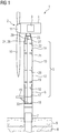
- Fig. 1 shows an offshore wind turbine 1 according to an embodiment.
- the wind turbine 1 comprises a rotor 2 connected to a generator 3 arranged inside a nacelle 4.
- the nacelle 4 is arranged at the upper end of a tower 5 of the wind turbine 1 by means of a yaw bearing (not shown) such that the nacelle 4 can rotate relative to the tower 5.
- the tower 5 comprises, for example, a transition piece 6 erected on a monopile 7.
- the monopile 7 is, for example, driven into a sea bed 8 and extends above the sea water 9.
- the rotor 2 comprises, for example, three rotor blades 10.
- the rotor blades 10 are connected to a hub 11 of the wind turbine 1.
- a shaft (not shown) connects the hub 11 via a gearbox (not shown) to the generator 3.
- the generator 3 is electrically connected to a switch gear (not shown) in the transition piece 6 of the tower 5.
- the tower 5 comprises, in addition to the transition piece 6, for example, one or more tower sections 12, 13, 14.
- the tower 5 comprises a bottom tower section 12, a middle tower section 13, and a top tower section 14.
- the tower 5 (e.g., the transition piece 6) comprises on its outside a landing platform 15 to provide access to the interior of the tower 5.
- the tower 5 comprises in its inside several platforms 16 to 23.
- the tower 5 comprises, for example, an entrance platform 17 arranged on the same level as the landing platform 15.
- the tower 5 comprises, for example, a low voltage platform 19 in the bottom tower section 12 on which a low voltage transformer (not shown) is located.
- the tower 5 comprises, for example, bolt platforms 18, 20 and 21 configured for a worker to bolt the corresponding tower sections 12, 13, 14 to each other or to the transition piece 6 when assembling the tower 5.
- the tower 5 comprises, for example, a lift platform 22 in the top tower section 14.
- the tower 5 comprises, for example, in the top tower section 14 a yaw platform 23 above the lift platform 22.
- a yaw system (not shown) for driving and/or controlling a yaw bearing (not shown) is arranged.
- the yaw system includes, for example, a yaw drive, a yaw brake and a yaw control system.
- the wind turbine 1 comprises inside its tower 5 a tower lift 24 for transporting a load from a lower platform, such as the entrance platform 17, to a higher platform, such as the lift platform 22 or vice versa.
- the tower lift 24 may also be configured to transport a load from any of the platforms 17, 18, 19, 20, 21, 22 to any other of these platforms.
- the tower lift 24 comprises a transport cabin 25 ( Fig. 2 ) to accommodate a load such as a passenger or an object.
- the transport cabin 25 is moving upwards and downwards within a lift shaft housing 26.
- the lift shaft housing 26 extends in the interior of the tower 5 at least from the lowest platform served by the lift 24, e.g., the entrance platform 17, to the highest platform served by the lift, e.g., the lift platform 22.
- the tower lift 24 comprises a motor (not shown) for driving the cabin 25.
- the tower lift 24 comprises several cables for carrying and guiding the transport cabin 25.
- the tower lift 24 comprises, in particular, a drive cable 27 attached on its one end to the cabin 25 and on its other end to a lift beam 28 integrated into the yaw platform 23 ( Fig. 2 ).
- the cabin 25 moves upwards, for example, by winding up the drive cable 27 by means of the motor such that the cabin 25 climbs along the drive cable 27.
- the tower lift 24 further comprises a safety cable 29 also attached on its one end to the cabin 25 and on its other end to the lift beam 28 of the yaw platform 23 ( Fig. 2 ).
- the safety cable 29 is configured for preventing the cabin 25 to fall down in case that the drive cable 27 breaks.
- the tower lift 24 further comprises guide cables 30, for example two guide cables 30.
- the guide cables 30 are attached on its one end to the lift beam 28 of the yaw platform 23 ( Fig. 2 ) and on its other end to a lower portion, for example the platform 16, of the wind turbine tower 5 ( Fig. 1 ).
- the lower portion, for example the platform 16, is, in particular located below the entrance platform 17.
- Each of the guide cables 30 is tensioned between the lift beam 28 of the yaw platform 23 and the platform 16.
- the guide cables 30 are arranged on a left and right side of the cabin 25, and they guide the cabin 25 during its up and down movement through the lift shaft 26.
- Fig. 2 shows a perspective and detailed view of the lift platform 22 and the yaw platform 23 of the wind turbine 1 of Fig. 1 .
- the lift platform 22 is the highest platform of the tower 5 served by the lift 24. Shown on the lift platform 22 in Fig. 2 is the upper portion of the lift shaft housing 26. The transport cabin 25 is moving inside the lift shaft housing 26. In Fig. 2 , the cabin 25 that has arrived on the lift platform 22 is illustrated in a dashed line. Shown on top of the lift shaft housing 26 are the drive cable 27, the safety cable 29 and the two guiding cables 30. The cables 27, 29, 30 are connected to the lift beam 28.
- Fig. 3 shows an enlarged view of a portion III of Fig. 2 illustrating the lift beam 28 in more detail.
- the lift beam 28 is an integral part of a bearing structure 31 of the yaw platform 23.
- the bearing structure 31 of the yaw platform 23 comprises the lift beam 28 and a remaining bearing structure 32.
- the remaining bearing structure 32 also comprises beams, as shown in Fig. 3 .
- the lift beam 28 is integrally formed with the remaining bearing structure 32 of the yaw platform 23.
- the lift beam 28 and the remaining bearing structure 32 are fixedly connected with each other, for example by welding or bolting.
- the yaw platform 23 comprises - in addition to the bearing structure 31 - also a floor plate 33 supported by the bearing structure 31.
- the floor plate 33 is shown in Fig. 3 as being transparent for illustration purposes.
- the floor plate 33 is arranged above the platform bearing structure 31, i.e. above the lift beam 28 and the remaining bearing structure 32.
- the lift beam 28 is advantageously arranged entirely below the floor plate 33 such that workers can perform work on the floor plate 33 without interfering with the lift beam 28.
- the floor plate 33 is, in particular, fixed to the lift beam 28 and the remaining bearing structure 32.
- the lift beam is configured for carrying the load of the transport cabin 25 ( Fig. 2 ) of the tower lift 24 from above.
- the lift cables 27, 29, 30 are attached to the lift beam 28 by attachment means 34.
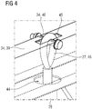
- Fig. 4 shows an enlarged view of a portion IV of Fig. 3 illustrating the attachment means 34 in detail.
- Fig. 5 shows a cross-section view of the attachment means 34 connected to the lift beam 28.
- the lift beam 28 has a double-C-shaped cross-section profile.
- the double-C-shaped cross-section profile comprises, in particular, two C-shaped profiles 35 arranged back-to-back with each other.
- Each C-shaped profile 35 comprises a web 36 and two flanges 37.
- the lift beam 28 comprises a gap 38.
- the lift beam 28 having the double-C-shaped cross-section profile comprises two separate longitudinal elements (beams) 35 being separated from each other by said gap 38.
- the lift cables 27, 29, 30 are passing through this gap.
- the drive cable 27 passing through the gap 38 is shown as example.
- the lift beam 28 is protruding from a lower surface 47 of the remaining bearing structure 32 of the yaw platform 23.
- the lift beam 28 may also be flush with the lower surface 47.
- the attachment means 34 include a bracket 39 and four pins 40 supported by the bracket 39 ( Figs. 3 to 5 ).
- each of the pins 40 is formed as a shaft of a bolt supported by the bracket 39.
- a split pin 41 to secure the pin 40.
- the bracket 39 has, for example, a top-hat cross-section profile ( Fig. 5 ).
- the top-hat profile of the bracket 39 comprises, in particular, two flanges 42 connected to an inverse U-shaped profile 43.
- the bracket 39 is, in particular, fixed to the lift beam 28 with the floor plate 33 arranged between the bracket 39 and the lift beam 28.
- the flanges 42 of the top-hat profile of the bracket 39 are bolted to the floor plate 33 and to upper flanges 37 of the double-C-shaped profile of the lift beam 28.
- the floor plate 33 also comprises openings 44 (in the shown example four openings for the four cables) for passage of the lift cables 27, 29, 30.
- the openings 44 of the floor plate 33 correspond to the gap 38 of the lift beam 28.
- the bracket 39 includes openings 45 (in the shown example four openings) at a top portion of the top-hat cross-section profile. The openings 45 of the bracket 39 correspond to the gap 38 of the lift beam 28 and the openings 44 of the floor plate 33.
- each of the lift cables 27, 29, 30 is guided through the gap 38 of the lift beam 28 and through the respective opening 44 of the floor plate 33.
- Each of the lift cables 27, 29, 30 comprises, for example, a loop 46.
- Each of the lift cables 27, 29, 30 is attached to the lift beam 28 by engaging the loop 46 with the pin 40, as shown in Figs. 4 and 5 .
- step S1 of the method the yaw platform 23 with the lift beam 28 ( Fig. 2 ) of the wind turbine 1 is manufactured.
- the platform 23 is, for example, manufactured in a factory at a first location.
- the yaw platform 23 is manufactured such that it comprises the lift beam 28 integrally formed with the remaining bearing structure 32 ( Fig. 3 ).
- step S2 of the method the pre-manufactured yaw platform 23 having the lift beam 28 is installed in the tower 5 of the wind turbine 1.
- the yaw platform 23 is inserted into the horizontally arranged tower 5, e.g., into the top tower section 14.
- Step S2 may include transporting the pre-manufactured yaw platform 23 to a second location before inserting the platform 23 into the tower 5.
- the second location is, in particular, different from the first location.
- the pre-manufactured yaw platform 23 is, for example, transported from the factory to a harbor site. Further, the yaw platform 23 having the lift beam 28 is, for example, installed in the tower 5 at the harbor site.
- the installation of the platform 23 with the lift beam 28 is performed in a single step and requires less components as in the case where the platform and the lift beam are two separate parts.
- step S3 of the method the tower lift 24 is installed in the wind turbine tower 5. Thereby, the lift cables 27, 29, 30 of the tower lift 24 are attached to the lift beam 28.
Landscapes
- Engineering & Computer Science (AREA)
- Life Sciences & Earth Sciences (AREA)
- Sustainable Development (AREA)
- Sustainable Energy (AREA)
- Chemical & Material Sciences (AREA)
- Combustion & Propulsion (AREA)
- Mechanical Engineering (AREA)
- General Engineering & Computer Science (AREA)
- Automation & Control Theory (AREA)
- Structural Engineering (AREA)
- Wind Motors (AREA)
Abstract
Description
- The present invention relates to a platform for a wind turbine, a wind turbine with the platform and a method for assembling a wind turbine.
- For transporting objects or passengers within a tower of a wind turbine upwards and downwards, wind turbines may comprise a tower lift inside. The tower lift can transport loads, for example, by moving a transport cabin from a lower platform to an upper platform of the tower. Above the highest tower platform served by the lift, a beam is required for carrying the load of the transport cabin.
- Conventionally, a lift beam for carrying the load of the transport cabin is installed above the highest tower platform. The lift beam is installed, for example, about half a meter above the highest tower platform by attaching it to the tower wall. The highest platform of the tower is usually the yaw platform. On the yaw platform, a yaw system is arranged for driving and controlling the yaw bearing of the wind turbine.
- However, the space between the yaw platform and the top flange of the tower is very limited. This is in particular the case as in this region the tower is usually strongly tapered towards the upper end of the tower. Further, in this limited space also the attachment means of the yaw platform are arranged. The yaw platform is, for example, attached by means of stays connected to the top flange of the tower. Due to the limited space, installation of a lift beam between the yaw platform and the top flange and its maintenance is difficult. Furthermore, lift guide wires hanging from the lift beam are positioned very close to the tower wall due to the steep coning of the wind turbine in this region.
- It is one object of the present invention to provide an improved platform for a wind turbine, an improved wind turbine with the platform and an improved method for assembling a wind turbine.
- Accordingly, a platform for a wind turbine is provided. The platform comprises a lift beam for carrying a load of a transport cabin of a tower lift of the wind turbine.
- By the lift beam being part of the platform, an easier installation of the platform and the lift beam is possible compared to the case where the platform and the lift beam are two separate parts which are required to be installed separately. Furthermore, less components are needed as the lift beam does not require extra wall attachment means. Further, the lift beam may replace a part of the platform bearing structure.
- Another advantage of the proposed platform with the lift beam is that the lift beam is installed at a lower height of the tower where the tower has a larger diameter compared to a conventional lift beam. This is the case as the tower in the topmost section is strongly tapered towards the upper tower end with the tower diameter becoming significantly smaller for larger tower heights. Having the lift beam not above, for example half a meter above, the platform but as part of the platform, therefore, increases the available space for lift cables hanging from the lift beam. In particular, it increases the available space for the guide cables of the tower lift.
- A wind turbine is an apparatus to convert the wind's kinetic energy into electrical energy. The wind turbine comprises, for example, a rotor having one or more blades, a nacelle comprising a generator and a tower holding, at its top end, the nacelle. The tower of the wind turbine, for example a transition piece of the tower, is connected to a foundation of the wind turbine such as a monopile in the sea bed.
- The platform comprising the lift beam is arranged inside the tower. The platform is, in particular, connected to the tower wall or to a tower flange. The platform is, for example, connected to the tower wall by means of wall brackets, or connected to the tower flange by means of stays.
- The lift beam has, for example, a longitudinal structure. The lift beam is, for example, made from metal such as steel.
- When the wind turbine tower with the platform having the lift beam is in an erected state, the lift beam is oriented horizontally with respect to a ground. In other words, when the wind turbine tower with the platform having the lift beam is in an erected state, the lift beam is oriented perpendicular to a longitudinal axis of the tower.
- The wind turbine comprises inside its tower a tower lift for transporting a load upwards or downwards within the tower. The tower lift is, for example, configured for transporting objects and/or passengers within the tower.
- The wind turbine tower may comprise inside - in addition to the platform having the lift beam - several further platforms on several levels. The tower lift is, for example, configured for transporting a load from a lower platform to a higher platform of these further platforms or vice versa. Furthermore, the tower lift may be configured to transport a load from any of the further platforms to any other of the further platforms.
- The tower lift is, for example, configured for transporting a load from an entrance platform to a platform above the entrance platform or vice versa. The entrance platform is, for example, a platform inside the tower being on the same level as a landing platform arranged outside the tower.
- The platform comprising the lift beam is, in particular, an upper platform, for example the highest platform, inside the tower. The platform comprising the lift beam is, for example, a yaw platform of the wind turbine tower. On the yaw platform, a yaw system is arranged for driving and/or controlling a yaw bearing of the wind turbine. The yaw bearing allows rotation of the nacelle relative to the tower in azimuthal direction for optimal orientation of the rotor of the wind turbine relative to the wind direction.
- The highest platform served by the tower lift ("lift platform"), is, for example, a platform below and next to the yaw platform of the tower.
- The tower lift comprises a transport cabin to accommodate the load to be transported. Further, the tower lift comprises one or more cables for carrying and/or guiding the transport cabin. The one or more cables of the tower lift are attached to the lift beam.
- The one or more cables of the tower lift include, for example, a drive cable, a safety cable and/or one or more guide cables. The drive cable and the safety cable are - in addition of being attached at a first end to the lift beam - attached at a second end to the transport cabin of the tower lift for carrying the transport cabin. The one or more guide cables are - in addition of being attached at a first end to the lift beam - attached at a second end to a lower portion of the wind turbine tower, the lower portion being arranged below the lowest platform served by the lift. This lower portion is, for example, a portion of an additional tower platform arranged below the lowest platform served by the lift. Further, the one or more guide cables are, in particular, tensioned between the lift beam and this lower portion.
- The tower lift comprises a motor for driving the lift. The motor is, for example, arranged on top of the transport cabin. The transport cabin is, for example, moving up inside the tower by climbing along the drive cable while the drive cable is wound up on a wheel by the motor.
- The tower lift further comprises a lift shaft formed by a housing. The lift shaft extends in the interior of the tower at least from the lowest platform served by the lift to the highest platform served by the lift. The transport cabin is moving upwards and downwards within the lift shaft. The tower lift further comprises the usual equipment necessary to operate a lift.
- According to an embodiment, the platform comprises a bearing structure and a floor plate supported by the bearing structure, wherein the bearing structure comprises the lift beam.
- Thus, the lift beam is not only carrying the load of the transport cabin of the lift but also functions together with the remaining bearing structure as genuine bearing structure of the platform. Further, the lift beam is not only carrying the load of the transport cabin of the lift but is also supporting together with the remaining bearing structure the floor plate.
- In particular, the platform bearing structure including the lift beam supports the floor plate from below. Further, the platform bearing structure, in particular the lift beam, is configured to support the load of the transport cabin of the tower lift from above.
- According to a further embodiment, the lift beam is integrally formed with the platform bearing structure.
- In particular, the platform bearing structure comprises the lift beam and a remaining bearing structure. The remaining bearing structure also comprises beams. Further, the lift beam and the remaining bearing structure are fixedly connected with each other. The lift beam and the remaining bearing structure are, for example, fixedly connected with each other by welding or bolting. In particular, the lift beam and the remaining bearing structure have a one-piece structure.
- According to a further embodiment, the floor plate is arranged above the platform bearing structure having the lift beam, and the floor plate is fixed to the lift beam.
- In particular, the lift beam is arranged below the floor plate. In particular, the lift beam is arranged entirely below the floor plate.
- Having the floor plate arranged above the lift beam, the lift beam is not interfering with objects, workers and/or work carried out on the floor plate.
- According to a further embodiment, the platform comprises attachment means connected to the lift beam and configured for attaching one or more cables of the tower lift to the lift beam.
- Thus, the lift cables can be attached to the platform having the lift beam, in particular, to the lift beam.
- According to a further embodiment, the attachment means protrude above the floorplate.
- Having the attachment means protruding above the floor plate allows a better maintenance and inspection of the lift cables and the connection between the lift cables and the lift beam. For example, a worker standing on the floor plate of the platform has an easy access to the top most portion of the lift cables, the connection region between the lift cables and the lift beam and/or the attachment means.
- According to a further embodiment, the lift beam comprises one or more openings for passage of one or more cables of the tower lift.
- By having the one or more openings of the lift beam, the lift cables can be better attached to the lift beam. In particular, a stronger connection between the lift cables and the lift beam can be achieved. For example, a force acting on the lift beam due to the load of the transport cabin hanging with the lift cables from the lift beam can be better transferred to the lift beam.
- The one or more openings are, for example, one or more through holes of the lift beam. Alternatively, the one or more openings are, for example, formed by one or more gaps of the lift beam. For example, the one or more openings are formed by a single gap of the lift beam.
- For example, also the floor plate comprises one or more openings for passage of the one or more cables of the tower lift, whereas the one or more openings of the floor plate correspond to the one or more openings of the lift beam.
- According to a further embodiment, the attachment means include one or more brackets and one or more pins supported by the one or more brackets, each pin being configured for connection with one of the cables of the tower lift.
- Thus, for example a loop of a lift cable or a hook of a lift cable can be engaged with the pin.
- The pin is, for example, extending in a direction perpendicular to a longitudinal axis of the tower in the erected state. The pin is, for example, extending in a direction perpendicular to a longitudinal direction of the lift beam in the installed state of the platform and the erected state of the tower.
- The pin is, for example, a shaft of a bolt.
- The attachment means include, for example, one bracket having a top-hat cross-section profile.
- The attachment means include, for example, one or more openings at a top portion of the top-hat cross-section profile allowing access to the lift cables. The one or more openings of the bracket correspond, for example, with the one or more openings of the lift beam. The one or more openings of the bracket correspond, for example, with the one or more openings of the floor plate.
- According to a further embodiment, the lift beam has a double-C-shaped cross-section profile.
- Having the double-C-shaped cross-section profile of the lift beam provides a simple and cheap configuration of the lift beam. Further, it allows to provide an opening for the lift cables in a simple manner.
- A double-C-shaped cross-section profile comprises, in particular, two C-shaped profiles arranged back-to-back with each other. The two C-shaped profiles are, for example, arranged back-to-back with each other such that there is a continuous gap between the two C-shaped profiles. In other words, the lift beam having the double-C-shaped cross-section profile comprises two separate longitudinal elements (beams) being separate from each other by said gap. The gap being configured for a passage of the lift cables.
- Each C-shaped profile comprises a web and two flanges. The lift beam is, in particular, oriented horizontally,
the web of each C-shaped profile is oriented vertically and its flanges are oriented horizontally with respect to a ground in the installed state of the platform and the erected state of the tower. - Alternatively, the lift beam may also comprise another cross-section profile. The lift beam may, for example, comprise an I-profile (H profile).
- According to a further embodiment, the attachment means include a bracket having a top-hat cross-section profile,
the lift beam has a gap between two back-to-back arranged C-shaped profiles of the double-C-shaped cross-section profile, the gap being configured for passage of one or more cables of the tower lift,
the attachment means are connected to the lift beam such that flanges of the top-hat profile are connected with upper flanges of the double-C-shaped profile, and/or
the attachment means include the one or more pins supported by the bracket, each pin being configured for connection with one of the cables of the tower lift when passed through the gap of the lift beam. - The top-hat profile of the bracket comprises, in particular, two flanges connected to an inverse U-shaped profile.
- The attachment means are connected to the lift beam, for example, by bolting. The attachment means are connected to the lift beam, for example, such that each one of the flanges of the top-hat profile is connected to an upper flange of the two flanges of each C-shaped profile.
- Further, the floor plate is, for example, arranged between the bracket und the lift beam such that the bracket, the floor plate and the lift beam are connected to each other. For example, the bracket is bolted to the floor plate and the lift beam.
- According to a second aspect, a wind turbine is provided. The wind turbine comprises:
- a tower,
- a lower platform and an upper platform inside the tower,
- a tower lift comprising a transport cabin for travelling from the lower platform to the upper platform or vice versa, and
- a platform with a lift beam as described above, wherein the platform is arranged inside the tower of the wind turbine above the upper platform, the lift beam of the platform carrying a load of the transport cabin of the tower lift.
- According to an embodiment of the second aspect, the tower lift comprises one or more cables attached to the lift beam of the platform.
- According to a further embodiment of the second aspect, the one or more cables of the tower lift include a drive cable, a safety cable and/or one or more guide cables, the drive cable and the safety cable being attached to the transport cabin of the tower lift for carrying the transport cabin, and the one or more guide cables being attached to a lower portion of the tower below the lower platform.
- According to a third aspect, a method for assembling a wind turbine is proposed. The method comprises the steps of:
- a) manufacturing a platform, the platform comprising a lift beam for bearing a load of a transport cabin of a tower lift, and
- b) installing the platform in a tower.
- According to an embodiment of the third aspect, the method comprises, after step b), the step of installing the tower lift in the wind turbine tower, wherein one or more cables of the tower lift are attached to the lift beam, and the one or more cables are configured for carrying and/or guiding the transport cabin of the tower lift.
- According to a further embodiment of the third aspect, the platform is a yaw platform.
- According to a further embodiment of the third aspect, the platform is fixed to a portion of a tower wall and/or a tower section flange of the wind turbine tower.
- The embodiments and features described with reference to the platform of the present invention apply mutatis mutandis to the wind turbine of the present invention and to the method of the present invention and vice versa.
- Further possible implementations or alternative solutions of the invention also encompass combinations - that are not explicitly mentioned herein - of features described above or below with regard to the embodiments. The person skilled in the art may also add individual or isolated aspects and features to the most basic form of the invention.
- Further embodiments, features and advantages of the present invention will become apparent from the subsequent description and dependent claims, taken in conjunction with the accompanying drawings, in which:
- Fig. 1
- shows, in partial cross-section, a wind turbine according to an embodiment;
- Fig. 2
- shows a perspective and detailed view of a portion of the wind turbine of
Fig. 1 ; - Fig. 3
- shows an enlarged view of a portion III of
Fig. 2 ; - Fig. 4
- shows an enlarged view of a portion IV of
Fig. 3 ; - Fig. 5
- shows a cross-section view of a lift beam and attachment means of
Fig. 3 ; and - Fig. 6
- shows a flowchart illustrating a method for assembling the wind turbine of
Fig. 1 . - In the Figures, like reference numerals designate like or functionally equivalent elements, unless otherwise indicated.
-
Fig. 1 shows anoffshore wind turbine 1 according to an embodiment. - The
wind turbine 1 comprises a rotor 2 connected to agenerator 3 arranged inside a nacelle 4. The nacelle 4 is arranged at the upper end of atower 5 of thewind turbine 1 by means of a yaw bearing (not shown) such that the nacelle 4 can rotate relative to thetower 5. Thetower 5 comprises, for example, atransition piece 6 erected on amonopile 7. Themonopile 7 is, for example, driven into asea bed 8 and extends above the sea water 9. - The rotor 2 comprises, for example, three
rotor blades 10. Therotor blades 10 are connected to ahub 11 of thewind turbine 1. A shaft (not shown) connects thehub 11 via a gearbox (not shown) to thegenerator 3. Thegenerator 3 is electrically connected to a switch gear (not shown) in thetransition piece 6 of thetower 5. - The
tower 5 comprises, in addition to thetransition piece 6, for example, one ormore tower sections Fig. 1 , thetower 5 comprises abottom tower section 12, amiddle tower section 13, and atop tower section 14. - The tower 5 (e.g., the transition piece 6) comprises on its outside a
landing platform 15 to provide access to the interior of thetower 5. - The
tower 5 comprises in its insideseveral platforms 16 to 23. Thetower 5 comprises, for example, anentrance platform 17 arranged on the same level as thelanding platform 15. Thetower 5 comprises, for example, alow voltage platform 19 in thebottom tower section 12 on which a low voltage transformer (not shown) is located. Thetower 5 comprises, for example,bolt platforms tower sections transition piece 6 when assembling thetower 5. Thetower 5 comprises, for example, alift platform 22 in thetop tower section 14. Thetower 5 comprises, for example, in the top tower section 14 ayaw platform 23 above thelift platform 22. On theyaw platform 23, a yaw system (not shown) for driving and/or controlling a yaw bearing (not shown) is arranged. The yaw system includes, for example, a yaw drive, a yaw brake and a yaw control system. - Furthermore, the
wind turbine 1 comprises inside its tower 5 a tower lift 24 for transporting a load from a lower platform, such as theentrance platform 17, to a higher platform, such as thelift platform 22 or vice versa. The tower lift 24 may also be configured to transport a load from any of theplatforms - The tower lift 24 comprises a transport cabin 25 (
Fig. 2 ) to accommodate a load such as a passenger or an object. Thetransport cabin 25 is moving upwards and downwards within a lift shaft housing 26. The lift shaft housing 26 extends in the interior of thetower 5 at least from the lowest platform served by the lift 24, e.g., theentrance platform 17, to the highest platform served by the lift, e.g., thelift platform 22. - The tower lift 24 comprises a motor (not shown) for driving the
cabin 25. The tower lift 24 comprises several cables for carrying and guiding thetransport cabin 25. The tower lift 24 comprises, in particular, adrive cable 27 attached on its one end to thecabin 25 and on its other end to alift beam 28 integrated into the yaw platform 23 (Fig. 2 ). Thecabin 25 moves upwards, for example, by winding up thedrive cable 27 by means of the motor such that thecabin 25 climbs along thedrive cable 27. - The tower lift 24 further comprises a
safety cable 29 also attached on its one end to thecabin 25 and on its other end to thelift beam 28 of the yaw platform 23 (Fig. 2 ). Thesafety cable 29 is configured for preventing thecabin 25 to fall down in case that thedrive cable 27 breaks. - The tower lift 24 further comprises
guide cables 30, for example twoguide cables 30. Theguide cables 30 are attached on its one end to thelift beam 28 of the yaw platform 23 (Fig. 2 ) and on its other end to a lower portion, for example theplatform 16, of the wind turbine tower 5 (Fig. 1 ). The lower portion, for example theplatform 16, is, in particular located below theentrance platform 17. Each of theguide cables 30 is tensioned between thelift beam 28 of theyaw platform 23 and theplatform 16. Theguide cables 30 are arranged on a left and right side of thecabin 25, and they guide thecabin 25 during its up and down movement through the lift shaft 26. -
Fig. 2 shows a perspective and detailed view of thelift platform 22 and theyaw platform 23 of thewind turbine 1 ofFig. 1 . - The
lift platform 22 is the highest platform of thetower 5 served by the lift 24. Shown on thelift platform 22 inFig. 2 is the upper portion of the lift shaft housing 26. Thetransport cabin 25 is moving inside the lift shaft housing 26. InFig. 2 , thecabin 25 that has arrived on thelift platform 22 is illustrated in a dashed line. Shown on top of the lift shaft housing 26 are thedrive cable 27, thesafety cable 29 and the two guidingcables 30. Thecables lift beam 28. -
Fig. 3 shows an enlarged view of a portion III ofFig. 2 illustrating thelift beam 28 in more detail. - The
lift beam 28 is an integral part of a bearing structure 31 of theyaw platform 23. The bearing structure 31 of theyaw platform 23 comprises thelift beam 28 and a remainingbearing structure 32. The remainingbearing structure 32 also comprises beams, as shown inFig. 3 . In particular, thelift beam 28 is integrally formed with the remainingbearing structure 32 of theyaw platform 23. In particular, thelift beam 28 and the remainingbearing structure 32 are fixedly connected with each other, for example by welding or bolting. - The
yaw platform 23 comprises - in addition to the bearing structure 31 - also afloor plate 33 supported by the bearing structure 31. Thefloor plate 33 is shown inFig. 3 as being transparent for illustration purposes. Thefloor plate 33 is arranged above the platform bearing structure 31, i.e. above thelift beam 28 and the remainingbearing structure 32. - Thus, the
lift beam 28 is advantageously arranged entirely below thefloor plate 33 such that workers can perform work on thefloor plate 33 without interfering with thelift beam 28. Thefloor plate 33 is, in particular, fixed to thelift beam 28 and the remainingbearing structure 32. - The lift beam is configured for carrying the load of the transport cabin 25 (
Fig. 2 ) of the tower lift 24 from above. For this purpose, thelift cables lift beam 28 by attachment means 34. As the attachment means 34 protrude above thefloor plate 33, maintenance and inspection of thelift cables floor plate 33. -
Fig. 4 shows an enlarged view of a portion IV ofFig. 3 illustrating the attachment means 34 in detail.Fig. 5 shows a cross-section view of the attachment means 34 connected to thelift beam 28. - As shown in
Fig. 5 , thelift beam 28 has a double-C-shaped cross-section profile. The double-C-shaped cross-section profile comprises, in particular, two C-shaped profiles 35 arranged back-to-back with each other. Each C-shaped profile 35 comprises aweb 36 and twoflanges 37. Between the two C-shaped profiles 35, thelift beam 28 comprises agap 38. In other words, thelift beam 28 having the double-C-shaped cross-section profile comprises two separate longitudinal elements (beams) 35 being separated from each other by saidgap 38. Thelift cables Fig. 5 , thedrive cable 27 passing through thegap 38 is shown as example. - Further, in the example of the figures (e.g.,
Fig. 5 ), thelift beam 28 is protruding from alower surface 47 of the remainingbearing structure 32 of theyaw platform 23. In another embodiment, thelift beam 28 may also be flush with thelower surface 47. - The attachment means 34 include a
bracket 39 and fourpins 40 supported by the bracket 39 (Figs. 3 to 5 ). In the example shown in the figures, each of thepins 40 is formed as a shaft of a bolt supported by thebracket 39. There is further arranged asplit pin 41 to secure thepin 40. - The
bracket 39 has, for example, a top-hat cross-section profile (Fig. 5 ). The top-hat profile of thebracket 39 comprises, in particular, twoflanges 42 connected to an inverseU-shaped profile 43. - The
bracket 39 is, in particular, fixed to thelift beam 28 with thefloor plate 33 arranged between thebracket 39 and thelift beam 28. In particular, theflanges 42 of the top-hat profile of thebracket 39 are bolted to thefloor plate 33 and toupper flanges 37 of the double-C-shaped profile of thelift beam 28. - The
floor plate 33 also comprises openings 44 (in the shown example four openings for the four cables) for passage of thelift cables openings 44 of thefloor plate 33 correspond to thegap 38 of thelift beam 28. Further, also thebracket 39 includes openings 45 (in the shown example four openings) at a top portion of the top-hat cross-section profile. Theopenings 45 of thebracket 39 correspond to thegap 38 of thelift beam 28 and theopenings 44 of thefloor plate 33. - For fixing the
lift cables lift beam 28, each of thelift cables gap 38 of thelift beam 28 and through therespective opening 44 of thefloor plate 33. Each of thelift cables lift cables lift beam 28 by engaging the loop 46 with thepin 40, as shown inFigs. 4 and5 . - In the following, a method for assembling the
wind turbine 1 ofFig. 1 is described with reference toFig. 6 . - In step S1 of the method, the
yaw platform 23 with the lift beam 28 (Fig. 2 ) of thewind turbine 1 is manufactured. Theplatform 23 is, for example, manufactured in a factory at a first location. Theyaw platform 23 is manufactured such that it comprises thelift beam 28 integrally formed with the remaining bearing structure 32 (Fig. 3 ). - In step S2 of the method, the
pre-manufactured yaw platform 23 having thelift beam 28 is installed in thetower 5 of thewind turbine 1. For example, theyaw platform 23 is inserted into the horizontally arrangedtower 5, e.g., into thetop tower section 14. - Step S2 may include transporting the
pre-manufactured yaw platform 23 to a second location before inserting theplatform 23 into thetower 5. The second location is, in particular, different from the first location. Thepre-manufactured yaw platform 23 is, for example, transported from the factory to a harbor site. Further, theyaw platform 23 having thelift beam 28 is, for example, installed in thetower 5 at the harbor site. - By the
lift beam 28 being integrally formed with theplatform 23, the installation of theplatform 23 with thelift beam 28 is performed in a single step and requires less components as in the case where the platform and the lift beam are two separate parts. - In step S3 of the method, the tower lift 24 is installed in the
wind turbine tower 5. Thereby, thelift cables lift beam 28. - Although the present invention has been described in accordance with preferred embodiments, it is obvious for the person skilled in the art that modifications are possible in all embodiments.
Claims (15)
- A platform (23) for a wind turbine (1), the platform comprising a lift beam (28) for carrying a load of a transport cabin (25) of a tower lift (24) of the wind turbine (1).
- The platform according to claim 1, comprising a bearing structure (31) and a floor plate (33) supported by the bearing structure (31), wherein the bearing structure (31) comprises the lift beam (28).
- The platform according to claim 2, wherein the lift beam (28) is integrally formed with the platform bearing structure (31) .
- The platform according to claim 2 or 3, wherein the floor plate (33) is arranged above the platform bearing structure (31) having the lift beam (28), and the floor plate (33) is fixed to the lift beam (28).
- The platform according to one of claims 1 - 4, comprising attachment means (34) connected to the lift beam (28) and configured for attaching one or more cables (27, 29, 30) of the tower lift (24) to the lift beam (28).
- The platform according to claim 5, wherein the attachment means (34) protrude above the floor plate (33).
- The platform according to one of claims 1 - 6, wherein the lift beam (28) comprises one or more openings (38) for passage of one or more cables (27, 29, 30) of the tower lift (24) .
- The platform according to one of claims 5 to 7, wherein the attachment means (34) include one or more brackets (39) and one or more pins (40) supported by the one or more brackets (39), each pin (40) being configured for connection with one of the cables (27, 29, 30) of the tower lift (24).
- The platform according to one of claims 1 - 8, wherein the lift beam (28) has a double-C-shaped cross-section profile.
- The platform according to claim 8 and 9, wherein:the attachment means (34) include a bracket (39) having a top-hat cross-section profile,the lift beam (28) has a gap (38) between two back-to-back arranged C-shaped profiles (35) of the double-C-shaped cross-section profile, the gap (38) being configured for passage of one or more cables (27, 29, 30) of the tower lift (24),the attachment means (34) are connected to the lift beam (28) such that flanges (42) of the top-hat profile are connected with upper flanges (37) of the double-C-shaped profile, and/orthe attachment means (34) include the one or more pins (40) supported by the bracket (39), each pin (40) being configured for connection with one of the cables (27, 29, 30) of the tower lift (24) when passed through the gap (38) of the lift beam (28).
- A wind turbine (1), comprising:a tower (5),a lower platform (17) and an upper platform (22) inside the tower (5),a tower lift (24) comprising a transport cabin (25) for travelling from the lower platform (17) to the upper platform (22) or vice versa, anda platform (23) according to one of claims 1 - 10, wherein the platform (23) is arranged inside the tower (5) of the wind turbine above the upper platform (22), the lift beam (28) of the platform (23) carrying a load of the transport cabin (25) of the tower lift (24).
- The wind turbine according to claim 11, wherein the tower lift (24) comprises one or more cables (27, 29, 30) attached to the lift beam (28) of the platform (23).
- The wind turbine according to claim 12, wherein the one or more cables (27, 29, 30) of the tower lift (24) include a drive cable (27), a safety cable (29) and/or one or more guide cables (30), the drive cable (27) and the safety cable (29) being attached to the transport cabin (25) of the tower lift (24) for carrying the transport cabin (25), and the one or more guide cables (30) being attached to a lower portion (16) of the tower (5) below the lower platform (17).
- A method for assembling a wind turbine (1), comprising the steps of:a) manufacturing (S1) a platform (23), the platform (23) comprising a lift beam (28) for bearing a load of a transport cabin (25) of a tower lift (24), andb) installing (S2) the platform (23) in a tower (5).
- The method according to claim 14, comprising, after step b), the step of installing (S3) the tower lift (24) in the wind turbine tower (5), wherein one or more cables (27, 29, 30) of the tower lift (24) are attached to the lift beam (28), and the one or more cables (27, 29, 30) are configured for carrying and/or guiding the transport cabin (25) of the tower lift (24).
Applications Claiming Priority (1)
| Application Number | Priority Date | Filing Date | Title |
|---|---|---|---|
| IN202031018590 | 2020-04-30 |
Publications (2)
| Publication Number | Publication Date |
|---|---|
| EP3904673A1 true EP3904673A1 (en) | 2021-11-03 |
| EP3904673B1 EP3904673B1 (en) | 2023-11-01 |
Family
ID=71266338
Family Applications (1)
| Application Number | Title | Priority Date | Filing Date |
|---|---|---|---|
| EP20182618.7A Active EP3904673B1 (en) | 2020-04-30 | 2020-06-26 | Platform for a wind turbine, wind turbine with the plat-form and method for assembling a wind turbine |
Country Status (3)
| Country | Link |
|---|---|
| US (1) | US11754049B2 (en) |
| EP (1) | EP3904673B1 (en) |
| CN (1) | CN113586368A (en) |
Citations (4)
| Publication number | Priority date | Publication date | Assignee | Title |
|---|---|---|---|---|
| US20110140437A1 (en) * | 2010-05-26 | 2011-06-16 | Satish Vemuri | Self-supporting platform for a wind turbine |
| WO2012052583A1 (en) * | 2010-10-18 | 2012-04-26 | Omega Elevator S.A. | Elevator for wind towers and similar |
| KR101524158B1 (en) * | 2014-02-19 | 2015-05-29 | 삼성중공업 주식회사 | Rising and falling apparatus for tower of wind turbine |
| WO2015078476A1 (en) * | 2013-11-27 | 2015-06-04 | Vestas Wind Systems A/S | An internal tower structure for a wind turbine generator |
Family Cites Families (11)
| Publication number | Priority date | Publication date | Assignee | Title |
|---|---|---|---|---|
| US1815429A (en) * | 1928-09-08 | 1931-07-21 | Jesse L Canaday | Garage |
| US3851736A (en) * | 1973-03-20 | 1974-12-03 | Westinghouse Electric Corp | Apparatus and method for installing elevator hoistway equipment |
| US6425463B1 (en) * | 2000-03-15 | 2002-07-30 | Frederick Kenneth Broyan | Non-personnel lifting device |
| CN100389056C (en) * | 2003-03-06 | 2008-05-21 | 因温特奥股份公司 | elevator |
| DE102009041982A1 (en) * | 2009-09-17 | 2011-04-14 | Schuler Pressen Gmbh & Co. Kg | Method for cable assembly in the tower of a wind turbine |
| US9022739B2 (en) * | 2011-02-07 | 2015-05-05 | Vestas Wind Systems A/S | Wind turbine generator with a lifting device |
| US9057205B2 (en) * | 2012-01-06 | 2015-06-16 | General Electric Company | Platform assembly for a wind turbine tower |
| ES2901435T3 (en) * | 2013-07-17 | 2022-03-22 | Alimak Group Man Ab | lift system |
| DE102014218073A1 (en) * | 2014-09-10 | 2016-03-10 | Dywidag-Systems International Gmbh | Method for introducing a plurality of tendons into a tower using a crane and unwinding device for use in this method |
| US20180313106A1 (en) * | 2017-04-26 | 2018-11-01 | Wind Tower Technologies, Llc | Internal column and platform structures in a tower |
| CN209228538U (en) * | 2018-12-18 | 2019-08-09 | 北京金风科创风电设备有限公司 | Cable hoisting component |
-
2020
- 2020-06-26 EP EP20182618.7A patent/EP3904673B1/en active Active
-
2021
- 2021-04-29 US US17/244,449 patent/US11754049B2/en active Active
- 2021-04-30 CN CN202110482001.4A patent/CN113586368A/en active Pending
Patent Citations (4)
| Publication number | Priority date | Publication date | Assignee | Title |
|---|---|---|---|---|
| US20110140437A1 (en) * | 2010-05-26 | 2011-06-16 | Satish Vemuri | Self-supporting platform for a wind turbine |
| WO2012052583A1 (en) * | 2010-10-18 | 2012-04-26 | Omega Elevator S.A. | Elevator for wind towers and similar |
| WO2015078476A1 (en) * | 2013-11-27 | 2015-06-04 | Vestas Wind Systems A/S | An internal tower structure for a wind turbine generator |
| KR101524158B1 (en) * | 2014-02-19 | 2015-05-29 | 삼성중공업 주식회사 | Rising and falling apparatus for tower of wind turbine |
Also Published As
| Publication number | Publication date |
|---|---|
| CN113586368A (en) | 2021-11-02 |
| EP3904673B1 (en) | 2023-11-01 |
| US20210340959A1 (en) | 2021-11-04 |
| US11754049B2 (en) | 2023-09-12 |
Similar Documents
| Publication | Publication Date | Title |
|---|---|---|
| US10907614B2 (en) | Foundation building system for an offshore wind turbine and method for installation of an offshore wind turbine | |
| AU2003237665B2 (en) | Method for assembling/dismounting components of a wind power plant | |
| EP2038550B2 (en) | A tower construction for a wind turbine | |
| US9869293B2 (en) | Wind turbine tower guide system, and a method for installing an installation unit | |
| EP3891390B1 (en) | Method for manufacturing a wind turbine and tower of a wind turbine | |
| EP3317512B1 (en) | Method for moving wind turbine components and a transport system for moving wind turbine components | |
| US11286915B2 (en) | Standardized platform arrangement of a wind turbine | |
| EP2826742B1 (en) | Elevator system | |
| US20220127114A1 (en) | A wind turbine and a method for transporting cargo inside a wind turbine | |
| JP7271795B2 (en) | Attaching cables and other components to the wind turbine tower | |
| EP2194206A2 (en) | Method and system for coupling a stair platform to a tower of a wind energy turbine | |
| US12313040B2 (en) | Method of servicing a wind turbine rotor blade | |
| EP3904673B1 (en) | Platform for a wind turbine, wind turbine with the plat-form and method for assembling a wind turbine | |
| EP4388191B1 (en) | Temporary work platform assembly | |
| US11859592B2 (en) | Wind turbine | |
| EP4198302A1 (en) | Wind turbine with segmented cable arrangement | |
| DK202170410A1 (en) | Improvements relating to servicing of wind turbine blades | |
| WO2025008032A1 (en) | Improvements relating to service galleries in wind turbine towers | |
| BR102023019264A2 (en) | SELF-LIFTABLE PLATFORM FOR REPLACING WIND TURBINES BLADES |
Legal Events
| Date | Code | Title | Description |
|---|---|---|---|
| PUAI | Public reference made under article 153(3) epc to a published international application that has entered the european phase |
Free format text: ORIGINAL CODE: 0009012 |
|
| STAA | Information on the status of an ep patent application or granted ep patent |
Free format text: STATUS: THE APPLICATION HAS BEEN PUBLISHED |
|
| AK | Designated contracting states |
Kind code of ref document: A1 Designated state(s): AL AT BE BG CH CY CZ DE DK EE ES FI FR GB GR HR HU IE IS IT LI LT LU LV MC MK MT NL NO PL PT RO RS SE SI SK SM TR |
|
| B565 | Issuance of search results under rule 164(2) epc |
Effective date: 20210122 |
|
| STAA | Information on the status of an ep patent application or granted ep patent |
Free format text: STATUS: REQUEST FOR EXAMINATION WAS MADE |
|
| 17P | Request for examination filed |
Effective date: 20220503 |
|
| RBV | Designated contracting states (corrected) |
Designated state(s): AL AT BE BG CH CY CZ DE DK EE ES FI FR GB GR HR HU IE IS IT LI LT LU LV MC MK MT NL NO PL PT RO RS SE SI SK SM TR |
|
| GRAP | Despatch of communication of intention to grant a patent |
Free format text: ORIGINAL CODE: EPIDOSNIGR1 |
|
| STAA | Information on the status of an ep patent application or granted ep patent |
Free format text: STATUS: GRANT OF PATENT IS INTENDED |
|
| RIC1 | Information provided on ipc code assigned before grant |
Ipc: B66B 9/00 20060101ALI20230522BHEP Ipc: F03D 80/80 20160101ALI20230522BHEP Ipc: F03D 13/10 20160101AFI20230522BHEP |
|
| INTG | Intention to grant announced |
Effective date: 20230613 |
|
| GRAS | Grant fee paid |
Free format text: ORIGINAL CODE: EPIDOSNIGR3 |
|
| GRAA | (expected) grant |
Free format text: ORIGINAL CODE: 0009210 |
|
| STAA | Information on the status of an ep patent application or granted ep patent |
Free format text: STATUS: THE PATENT HAS BEEN GRANTED |
|
| REG | Reference to a national code |
Ref country code: DE Ref legal event code: R082 Ref document number: 602020020114 Country of ref document: DE Representative=s name: SAUTHOFF, KARSTEN, DIPL.-ING. UNIV., DE |
|
| AK | Designated contracting states |
Kind code of ref document: B1 Designated state(s): AL AT BE BG CH CY CZ DE DK EE ES FI FR GB GR HR HU IE IS IT LI LT LU LV MC MK MT NL NO PL PT RO RS SE SI SK SM TR |
|
| REG | Reference to a national code |
Ref country code: GB Ref legal event code: FG4D |
|
| REG | Reference to a national code |
Ref country code: CH Ref legal event code: EP |
|
| REG | Reference to a national code |
Ref country code: IE Ref legal event code: FG4D |
|
| REG | Reference to a national code |
Ref country code: DE Ref legal event code: R096 Ref document number: 602020020114 Country of ref document: DE |
|
| REG | Reference to a national code |
Ref country code: LT Ref legal event code: MG9D |
|
| REG | Reference to a national code |
Ref country code: NL Ref legal event code: MP Effective date: 20231101 |
|
| PG25 | Lapsed in a contracting state [announced via postgrant information from national office to epo] |
Ref country code: GR Free format text: LAPSE BECAUSE OF FAILURE TO SUBMIT A TRANSLATION OF THE DESCRIPTION OR TO PAY THE FEE WITHIN THE PRESCRIBED TIME-LIMIT Effective date: 20240202 |
|
| PG25 | Lapsed in a contracting state [announced via postgrant information from national office to epo] |
Ref country code: IS Free format text: LAPSE BECAUSE OF FAILURE TO SUBMIT A TRANSLATION OF THE DESCRIPTION OR TO PAY THE FEE WITHIN THE PRESCRIBED TIME-LIMIT Effective date: 20240301 |
|
| PG25 | Lapsed in a contracting state [announced via postgrant information from national office to epo] |
Ref country code: LT Free format text: LAPSE BECAUSE OF FAILURE TO SUBMIT A TRANSLATION OF THE DESCRIPTION OR TO PAY THE FEE WITHIN THE PRESCRIBED TIME-LIMIT Effective date: 20231101 |
|
| REG | Reference to a national code |
Ref country code: AT Ref legal event code: MK05 Ref document number: 1627470 Country of ref document: AT Kind code of ref document: T Effective date: 20231101 |
|
| PG25 | Lapsed in a contracting state [announced via postgrant information from national office to epo] |
Ref country code: NL Free format text: LAPSE BECAUSE OF FAILURE TO SUBMIT A TRANSLATION OF THE DESCRIPTION OR TO PAY THE FEE WITHIN THE PRESCRIBED TIME-LIMIT Effective date: 20231101 |
|
| PG25 | Lapsed in a contracting state [announced via postgrant information from national office to epo] |
Ref country code: AT Free format text: LAPSE BECAUSE OF FAILURE TO SUBMIT A TRANSLATION OF THE DESCRIPTION OR TO PAY THE FEE WITHIN THE PRESCRIBED TIME-LIMIT Effective date: 20231101 |
|
| PG25 | Lapsed in a contracting state [announced via postgrant information from national office to epo] |
Ref country code: ES Free format text: LAPSE BECAUSE OF FAILURE TO SUBMIT A TRANSLATION OF THE DESCRIPTION OR TO PAY THE FEE WITHIN THE PRESCRIBED TIME-LIMIT Effective date: 20231101 |
|
| PG25 | Lapsed in a contracting state [announced via postgrant information from national office to epo] |
Ref country code: NL Free format text: LAPSE BECAUSE OF FAILURE TO SUBMIT A TRANSLATION OF THE DESCRIPTION OR TO PAY THE FEE WITHIN THE PRESCRIBED TIME-LIMIT Effective date: 20231101 Ref country code: LT Free format text: LAPSE BECAUSE OF FAILURE TO SUBMIT A TRANSLATION OF THE DESCRIPTION OR TO PAY THE FEE WITHIN THE PRESCRIBED TIME-LIMIT Effective date: 20231101 Ref country code: IS Free format text: LAPSE BECAUSE OF FAILURE TO SUBMIT A TRANSLATION OF THE DESCRIPTION OR TO PAY THE FEE WITHIN THE PRESCRIBED TIME-LIMIT Effective date: 20240301 Ref country code: GR Free format text: LAPSE BECAUSE OF FAILURE TO SUBMIT A TRANSLATION OF THE DESCRIPTION OR TO PAY THE FEE WITHIN THE PRESCRIBED TIME-LIMIT Effective date: 20240202 Ref country code: ES Free format text: LAPSE BECAUSE OF FAILURE TO SUBMIT A TRANSLATION OF THE DESCRIPTION OR TO PAY THE FEE WITHIN THE PRESCRIBED TIME-LIMIT Effective date: 20231101 Ref country code: BG Free format text: LAPSE BECAUSE OF FAILURE TO SUBMIT A TRANSLATION OF THE DESCRIPTION OR TO PAY THE FEE WITHIN THE PRESCRIBED TIME-LIMIT Effective date: 20240201 Ref country code: AT Free format text: LAPSE BECAUSE OF FAILURE TO SUBMIT A TRANSLATION OF THE DESCRIPTION OR TO PAY THE FEE WITHIN THE PRESCRIBED TIME-LIMIT Effective date: 20231101 Ref country code: PT Free format text: LAPSE BECAUSE OF FAILURE TO SUBMIT A TRANSLATION OF THE DESCRIPTION OR TO PAY THE FEE WITHIN THE PRESCRIBED TIME-LIMIT Effective date: 20240301 |
|
| PG25 | Lapsed in a contracting state [announced via postgrant information from national office to epo] |
Ref country code: SE Free format text: LAPSE BECAUSE OF FAILURE TO SUBMIT A TRANSLATION OF THE DESCRIPTION OR TO PAY THE FEE WITHIN THE PRESCRIBED TIME-LIMIT Effective date: 20231101 Ref country code: RS Free format text: LAPSE BECAUSE OF FAILURE TO SUBMIT A TRANSLATION OF THE DESCRIPTION OR TO PAY THE FEE WITHIN THE PRESCRIBED TIME-LIMIT Effective date: 20231101 Ref country code: PL Free format text: LAPSE BECAUSE OF FAILURE TO SUBMIT A TRANSLATION OF THE DESCRIPTION OR TO PAY THE FEE WITHIN THE PRESCRIBED TIME-LIMIT Effective date: 20231101 Ref country code: NO Free format text: LAPSE BECAUSE OF FAILURE TO SUBMIT A TRANSLATION OF THE DESCRIPTION OR TO PAY THE FEE WITHIN THE PRESCRIBED TIME-LIMIT Effective date: 20240201 Ref country code: LV Free format text: LAPSE BECAUSE OF FAILURE TO SUBMIT A TRANSLATION OF THE DESCRIPTION OR TO PAY THE FEE WITHIN THE PRESCRIBED TIME-LIMIT Effective date: 20231101 Ref country code: HR Free format text: LAPSE BECAUSE OF FAILURE TO SUBMIT A TRANSLATION OF THE DESCRIPTION OR TO PAY THE FEE WITHIN THE PRESCRIBED TIME-LIMIT Effective date: 20231101 |
|
| PG25 | Lapsed in a contracting state [announced via postgrant information from national office to epo] |
Ref country code: DK Free format text: LAPSE BECAUSE OF FAILURE TO SUBMIT A TRANSLATION OF THE DESCRIPTION OR TO PAY THE FEE WITHIN THE PRESCRIBED TIME-LIMIT Effective date: 20231101 |
|
| PG25 | Lapsed in a contracting state [announced via postgrant information from national office to epo] |
Ref country code: CZ Free format text: LAPSE BECAUSE OF FAILURE TO SUBMIT A TRANSLATION OF THE DESCRIPTION OR TO PAY THE FEE WITHIN THE PRESCRIBED TIME-LIMIT Effective date: 20231101 |
|
| PG25 | Lapsed in a contracting state [announced via postgrant information from national office to epo] |
Ref country code: SK Free format text: LAPSE BECAUSE OF FAILURE TO SUBMIT A TRANSLATION OF THE DESCRIPTION OR TO PAY THE FEE WITHIN THE PRESCRIBED TIME-LIMIT Effective date: 20231101 |
|
| PG25 | Lapsed in a contracting state [announced via postgrant information from national office to epo] |
Ref country code: SM Free format text: LAPSE BECAUSE OF FAILURE TO SUBMIT A TRANSLATION OF THE DESCRIPTION OR TO PAY THE FEE WITHIN THE PRESCRIBED TIME-LIMIT Effective date: 20231101 Ref country code: SK Free format text: LAPSE BECAUSE OF FAILURE TO SUBMIT A TRANSLATION OF THE DESCRIPTION OR TO PAY THE FEE WITHIN THE PRESCRIBED TIME-LIMIT Effective date: 20231101 Ref country code: IT Free format text: LAPSE BECAUSE OF FAILURE TO SUBMIT A TRANSLATION OF THE DESCRIPTION OR TO PAY THE FEE WITHIN THE PRESCRIBED TIME-LIMIT Effective date: 20231101 Ref country code: EE Free format text: LAPSE BECAUSE OF FAILURE TO SUBMIT A TRANSLATION OF THE DESCRIPTION OR TO PAY THE FEE WITHIN THE PRESCRIBED TIME-LIMIT Effective date: 20231101 Ref country code: DK Free format text: LAPSE BECAUSE OF FAILURE TO SUBMIT A TRANSLATION OF THE DESCRIPTION OR TO PAY THE FEE WITHIN THE PRESCRIBED TIME-LIMIT Effective date: 20231101 Ref country code: CZ Free format text: LAPSE BECAUSE OF FAILURE TO SUBMIT A TRANSLATION OF THE DESCRIPTION OR TO PAY THE FEE WITHIN THE PRESCRIBED TIME-LIMIT Effective date: 20231101 |
|
| REG | Reference to a national code |
Ref country code: DE Ref legal event code: R097 Ref document number: 602020020114 Country of ref document: DE |
|
| PLBE | No opposition filed within time limit |
Free format text: ORIGINAL CODE: 0009261 |
|
| STAA | Information on the status of an ep patent application or granted ep patent |
Free format text: STATUS: NO OPPOSITION FILED WITHIN TIME LIMIT |
|
| 26N | No opposition filed |
Effective date: 20240802 |
|
| PG25 | Lapsed in a contracting state [announced via postgrant information from national office to epo] |
Ref country code: SI Free format text: LAPSE BECAUSE OF FAILURE TO SUBMIT A TRANSLATION OF THE DESCRIPTION OR TO PAY THE FEE WITHIN THE PRESCRIBED TIME-LIMIT Effective date: 20231101 |
|
| PG25 | Lapsed in a contracting state [announced via postgrant information from national office to epo] |
Ref country code: SI Free format text: LAPSE BECAUSE OF FAILURE TO SUBMIT A TRANSLATION OF THE DESCRIPTION OR TO PAY THE FEE WITHIN THE PRESCRIBED TIME-LIMIT Effective date: 20231101 |
|
| PG25 | Lapsed in a contracting state [announced via postgrant information from national office to epo] |
Ref country code: MC Free format text: LAPSE BECAUSE OF FAILURE TO SUBMIT A TRANSLATION OF THE DESCRIPTION OR TO PAY THE FEE WITHIN THE PRESCRIBED TIME-LIMIT Effective date: 20231101 |
|
| REG | Reference to a national code |
Ref country code: CH Ref legal event code: PL |
|
| PG25 | Lapsed in a contracting state [announced via postgrant information from national office to epo] |
Ref country code: LU Free format text: LAPSE BECAUSE OF NON-PAYMENT OF DUE FEES Effective date: 20240626 |
|
| PG25 | Lapsed in a contracting state [announced via postgrant information from national office to epo] |
Ref country code: IE Free format text: LAPSE BECAUSE OF NON-PAYMENT OF DUE FEES Effective date: 20240626 |
|
| PG25 | Lapsed in a contracting state [announced via postgrant information from national office to epo] |
Ref country code: BE Free format text: LAPSE BECAUSE OF NON-PAYMENT OF DUE FEES Effective date: 20240630 Ref country code: CH Free format text: LAPSE BECAUSE OF NON-PAYMENT OF DUE FEES Effective date: 20240630 |
|
| REG | Reference to a national code |
Ref country code: BE Ref legal event code: MM Effective date: 20240630 |
|
| PGFP | Annual fee paid to national office [announced via postgrant information from national office to epo] |
Ref country code: DE Payment date: 20250626 Year of fee payment: 6 |
|
| PGFP | Annual fee paid to national office [announced via postgrant information from national office to epo] |
Ref country code: GB Payment date: 20250617 Year of fee payment: 6 |
|
| PGFP | Annual fee paid to national office [announced via postgrant information from national office to epo] |
Ref country code: FR Payment date: 20250624 Year of fee payment: 6 |
|
| PG25 | Lapsed in a contracting state [announced via postgrant information from national office to epo] |
Ref country code: FI Free format text: LAPSE BECAUSE OF FAILURE TO SUBMIT A TRANSLATION OF THE DESCRIPTION OR TO PAY THE FEE WITHIN THE PRESCRIBED TIME-LIMIT Effective date: 20231101 |
|
| PG25 | Lapsed in a contracting state [announced via postgrant information from national office to epo] |
Ref country code: RO Free format text: LAPSE BECAUSE OF FAILURE TO SUBMIT A TRANSLATION OF THE DESCRIPTION OR TO PAY THE FEE WITHIN THE PRESCRIBED TIME-LIMIT Effective date: 20231101 |
|
| PG25 | Lapsed in a contracting state [announced via postgrant information from national office to epo] |
Ref country code: CY Free format text: LAPSE BECAUSE OF FAILURE TO SUBMIT A TRANSLATION OF THE DESCRIPTION OR TO PAY THE FEE WITHIN THE PRESCRIBED TIME-LIMIT; INVALID AB INITIO Effective date: 20200626 |
|
| PG25 | Lapsed in a contracting state [announced via postgrant information from national office to epo] |
Ref country code: HU Free format text: LAPSE BECAUSE OF FAILURE TO SUBMIT A TRANSLATION OF THE DESCRIPTION OR TO PAY THE FEE WITHIN THE PRESCRIBED TIME-LIMIT; INVALID AB INITIO Effective date: 20200626 |