EP3904671A1 - Condition monitoring device and condition monitoring method for wind turbine power generating apparatus - Google Patents
Condition monitoring device and condition monitoring method for wind turbine power generating apparatus Download PDFInfo
- Publication number
- EP3904671A1 EP3904671A1 EP21170028.1A EP21170028A EP3904671A1 EP 3904671 A1 EP3904671 A1 EP 3904671A1 EP 21170028 A EP21170028 A EP 21170028A EP 3904671 A1 EP3904671 A1 EP 3904671A1
- Authority
- EP
- European Patent Office
- Prior art keywords
- auxiliary
- current
- motor
- period
- condition monitoring
- Prior art date
- Legal status (The legal status is an assumption and is not a legal conclusion. Google has not performed a legal analysis and makes no representation as to the accuracy of the status listed.)
- Granted
Links
Images




Classifications
-
- F—MECHANICAL ENGINEERING; LIGHTING; HEATING; WEAPONS; BLASTING
- F03—MACHINES OR ENGINES FOR LIQUIDS; WIND, SPRING, OR WEIGHT MOTORS; PRODUCING MECHANICAL POWER OR A REACTIVE PROPULSIVE THRUST, NOT OTHERWISE PROVIDED FOR
- F03D—WIND MOTORS
- F03D7/00—Controlling wind motors
- F03D7/02—Controlling wind motors the wind motors having rotation axis substantially parallel to the air flow entering the rotor
- F03D7/0264—Controlling wind motors the wind motors having rotation axis substantially parallel to the air flow entering the rotor for stopping; controlling in emergency situations
-
- F—MECHANICAL ENGINEERING; LIGHTING; HEATING; WEAPONS; BLASTING
- F03—MACHINES OR ENGINES FOR LIQUIDS; WIND, SPRING, OR WEIGHT MOTORS; PRODUCING MECHANICAL POWER OR A REACTIVE PROPULSIVE THRUST, NOT OTHERWISE PROVIDED FOR
- F03D—WIND MOTORS
- F03D17/00—Monitoring or testing of wind motors, e.g. diagnostics
-
- F—MECHANICAL ENGINEERING; LIGHTING; HEATING; WEAPONS; BLASTING
- F03—MACHINES OR ENGINES FOR LIQUIDS; WIND, SPRING, OR WEIGHT MOTORS; PRODUCING MECHANICAL POWER OR A REACTIVE PROPULSIVE THRUST, NOT OTHERWISE PROVIDED FOR
- F03D—WIND MOTORS
- F03D17/00—Monitoring or testing of wind motors, e.g. diagnostics
- F03D17/027—Monitoring or testing of wind motors, e.g. diagnostics characterised by the component being monitored or tested
- F03D17/029—Blade pitch or yaw drive systems, e.g. pitch or yaw angle
-
- F—MECHANICAL ENGINEERING; LIGHTING; HEATING; WEAPONS; BLASTING
- F03—MACHINES OR ENGINES FOR LIQUIDS; WIND, SPRING, OR WEIGHT MOTORS; PRODUCING MECHANICAL POWER OR A REACTIVE PROPULSIVE THRUST, NOT OTHERWISE PROVIDED FOR
- F03D—WIND MOTORS
- F03D7/00—Controlling wind motors
- F03D7/02—Controlling wind motors the wind motors having rotation axis substantially parallel to the air flow entering the rotor
- F03D7/022—Adjusting aerodynamic properties of the blades
- F03D7/0224—Adjusting blade pitch
-
- F—MECHANICAL ENGINEERING; LIGHTING; HEATING; WEAPONS; BLASTING
- F03—MACHINES OR ENGINES FOR LIQUIDS; WIND, SPRING, OR WEIGHT MOTORS; PRODUCING MECHANICAL POWER OR A REACTIVE PROPULSIVE THRUST, NOT OTHERWISE PROVIDED FOR
- F03D—WIND MOTORS
- F03D80/00—Details, components or accessories not provided for in groups F03D1/00 - F03D17/00
- F03D80/003—Power-supply to auxiliary components, e.g. to pitch drives or cooling fans
-
- F—MECHANICAL ENGINEERING; LIGHTING; HEATING; WEAPONS; BLASTING
- F03—MACHINES OR ENGINES FOR LIQUIDS; WIND, SPRING, OR WEIGHT MOTORS; PRODUCING MECHANICAL POWER OR A REACTIVE PROPULSIVE THRUST, NOT OTHERWISE PROVIDED FOR
- F03D—WIND MOTORS
- F03D9/00—Adaptations of wind motors for special use; Combinations of wind motors with apparatus driven thereby; Wind motors specially adapted for installation in particular locations
- F03D9/20—Wind motors characterised by the driven apparatus
- F03D9/25—Wind motors characterised by the driven apparatus the apparatus being an electrical generator
-
- G—PHYSICS
- G01—MEASURING; TESTING
- G01R—MEASURING ELECTRIC VARIABLES; MEASURING MAGNETIC VARIABLES
- G01R19/00—Arrangements for measuring currents or voltages or for indicating presence or sign thereof
-
- G—PHYSICS
- G01—MEASURING; TESTING
- G01R—MEASURING ELECTRIC VARIABLES; MEASURING MAGNETIC VARIABLES
- G01R19/00—Arrangements for measuring currents or voltages or for indicating presence or sign thereof
- G01R19/0092—Measuring current only
-
- G—PHYSICS
- G01—MEASURING; TESTING
- G01R—MEASURING ELECTRIC VARIABLES; MEASURING MAGNETIC VARIABLES
- G01R19/00—Arrangements for measuring currents or voltages or for indicating presence or sign thereof
- G01R19/30—Measuring the maximum or the minimum value of current or voltage reached in a time interval
-
- G—PHYSICS
- G01—MEASURING; TESTING
- G01R—MEASURING ELECTRIC VARIABLES; MEASURING MAGNETIC VARIABLES
- G01R21/00—Arrangements for measuring electric power or power factor
- G01R21/06—Arrangements for measuring electric power or power factor by measuring current and voltage
-
- F—MECHANICAL ENGINEERING; LIGHTING; HEATING; WEAPONS; BLASTING
- F05—INDEXING SCHEMES RELATING TO ENGINES OR PUMPS IN VARIOUS SUBCLASSES OF CLASSES F01-F04
- F05B—INDEXING SCHEME RELATING TO WIND, SPRING, WEIGHT, INERTIA OR LIKE MOTORS, TO MACHINES OR ENGINES FOR LIQUIDS COVERED BY SUBCLASSES F03B, F03D AND F03G
- F05B2220/00—Application
- F05B2220/70—Application in combination with
- F05B2220/706—Application in combination with an electrical generator
- F05B2220/7064—Application in combination with an electrical generator of the alternating current (A.C.) type
-
- F—MECHANICAL ENGINEERING; LIGHTING; HEATING; WEAPONS; BLASTING
- F05—INDEXING SCHEMES RELATING TO ENGINES OR PUMPS IN VARIOUS SUBCLASSES OF CLASSES F01-F04
- F05B—INDEXING SCHEME RELATING TO WIND, SPRING, WEIGHT, INERTIA OR LIKE MOTORS, TO MACHINES OR ENGINES FOR LIQUIDS COVERED BY SUBCLASSES F03B, F03D AND F03G
- F05B2260/00—Function
- F05B2260/80—Diagnostics
-
- F—MECHANICAL ENGINEERING; LIGHTING; HEATING; WEAPONS; BLASTING
- F05—INDEXING SCHEMES RELATING TO ENGINES OR PUMPS IN VARIOUS SUBCLASSES OF CLASSES F01-F04
- F05B—INDEXING SCHEME RELATING TO WIND, SPRING, WEIGHT, INERTIA OR LIKE MOTORS, TO MACHINES OR ENGINES FOR LIQUIDS COVERED BY SUBCLASSES F03B, F03D AND F03G
- F05B2270/00—Control
- F05B2270/30—Control parameters, e.g. input parameters
- F05B2270/32—Wind speeds
-
- F—MECHANICAL ENGINEERING; LIGHTING; HEATING; WEAPONS; BLASTING
- F05—INDEXING SCHEMES RELATING TO ENGINES OR PUMPS IN VARIOUS SUBCLASSES OF CLASSES F01-F04
- F05B—INDEXING SCHEME RELATING TO WIND, SPRING, WEIGHT, INERTIA OR LIKE MOTORS, TO MACHINES OR ENGINES FOR LIQUIDS COVERED BY SUBCLASSES F03B, F03D AND F03G
- F05B2270/00—Control
- F05B2270/30—Control parameters, e.g. input parameters
- F05B2270/342—Wave conditions, e.g. amplitude, frequency or direction
-
- F—MECHANICAL ENGINEERING; LIGHTING; HEATING; WEAPONS; BLASTING
- F05—INDEXING SCHEMES RELATING TO ENGINES OR PUMPS IN VARIOUS SUBCLASSES OF CLASSES F01-F04
- F05B—INDEXING SCHEME RELATING TO WIND, SPRING, WEIGHT, INERTIA OR LIKE MOTORS, TO MACHINES OR ENGINES FOR LIQUIDS COVERED BY SUBCLASSES F03B, F03D AND F03G
- F05B2270/00—Control
- F05B2270/80—Devices generating input signals, e.g. transducers, sensors, cameras or strain gauges
- F05B2270/803—Sampling thereof
-
- Y—GENERAL TAGGING OF NEW TECHNOLOGICAL DEVELOPMENTS; GENERAL TAGGING OF CROSS-SECTIONAL TECHNOLOGIES SPANNING OVER SEVERAL SECTIONS OF THE IPC; TECHNICAL SUBJECTS COVERED BY FORMER USPC CROSS-REFERENCE ART COLLECTIONS [XRACs] AND DIGESTS
- Y02—TECHNOLOGIES OR APPLICATIONS FOR MITIGATION OR ADAPTATION AGAINST CLIMATE CHANGE
- Y02E—REDUCTION OF GREENHOUSE GAS [GHG] EMISSIONS, RELATED TO ENERGY GENERATION, TRANSMISSION OR DISTRIBUTION
- Y02E10/00—Energy generation through renewable energy sources
- Y02E10/70—Wind energy
- Y02E10/72—Wind turbines with rotation axis in wind direction
Definitions
- the present disclosure relates to a condition monitoring device and a condition monitoring method for a wind turbine power generating apparatus.
- Patent Document 1 discloses an abnormality diagnosis method for performing abnormality diagnosis of a rotary machine including a motor, based on a reference sinusoidal signal waveform of a rated current of the motor.
- Patent Document 1 JP5733913B
- the wind turbine power generating apparatus is provided with an auxiliary system including a plurality of auxiliary motors such as fan motors and pump motors and an auxiliary motor power supply system for supplying power to the plurality of auxiliary motors.
- auxiliary motors such as fan motors and pump motors
- auxiliary motor power supply system for supplying power to the plurality of auxiliary motors.
- Patent Document 1 does not disclose specific knowledge regarding the condition monitoring of the auxiliary system of the wind turbine power generating apparatus.
- an object of the present disclosure is to provide a condition monitoring device and a condition monitoring method for a wind turbine power generating apparatus whereby it is possible to monitor the condition of the auxiliary system of the wind turbine power generating apparatus with a small number of components.
- a condition monitoring device for a wind turbine power generating apparatus for monitoring a condition of an auxiliary system of the wind turbine power generating apparatus
- the auxiliary system including a plurality of auxiliary motors and an auxiliary motor power supply system for supplying power to the plurality of auxiliary motors
- the auxiliary motor power supply system including a power-supply-side line connected to a power supply and a plurality of auxiliary-motor-side lines diverging from the power-supply-side line and connected to the plurality of auxiliary motors respectively
- the condition monitoring device comprises: a current measurement device for measuring a current flowing through the power-supply-side line; and a control device for controlling the plurality of auxiliary motors.
- the control device is configured to, when a generator of the wind turbine power generating apparatus is in a standby state where power generation is stopped at a low wind speed, execute a single sequential operation mode in which each of the plurality of auxiliary motors is singly and sequentially operated.
- the current measurement device is configured to measure a current flowing through the power-supply-side line during execution of the single sequential operation mode by the control device.
- a condition monitoring method for a wind turbine power generating apparatus for monitoring a condition of an auxiliary system of the wind turbine power generating apparatus
- the auxiliary system including a plurality of auxiliary motors and an auxiliary motor power supply system for supplying power to the plurality of auxiliary motors
- the auxiliary motor power supply system including a power-supply-side line connected to a power supply and a plurality of auxiliary-motor-side lines diverging from the power-supply-side line and connected to the plurality of auxiliary motors respectively
- the condition monitoring method comprises: a step of, when a generator of the wind turbine power generating apparatus is in a standby state where power generation is stopped at a low wind speed, executing a single sequential operation mode in which each of the plurality of auxiliary motors is singly and sequentially operated; and a step of measuring a current flowing through the power-supply-side line during execution of the single sequential operation mode.
- the present disclosure provides a condition monitoring device and a condition monitoring method for a wind turbine power generating apparatus whereby it is possible to monitor the condition of the auxiliary system of the wind turbine power generating apparatus with a small number of components.
- an expression of relative or absolute arrangement such as “in a direction”, “along a direction”, “parallel”, “orthogonal”, “centered”, “concentric” and “coaxial” shall not be construed as indicating only the arrangement in a strict literal sense, but also includes a state where the arrangement is relatively displaced by a tolerance, or by an angle or a distance whereby it is possible to achieve the same function.
- an expression of an equal state such as “same” “equal” and “uniform” shall not be construed as indicating only the state in which the feature is strictly equal, but also includes a state in which there is a tolerance or a difference that can still achieve the same function.
- an expression of a shape such as a rectangular shape or a cylindrical shape shall not be construed as only the geometrically strict shape, but also includes a shape with unevenness or chamfered corners within the range in which the same effect can be achieved.
- FIG. 1 is a schematic diagram showing a configuration example of a wind turbine power generating apparatus 100 (hereinafter, also referred to as "wind turbine”) to be monitored by a condition monitoring device, which will be described later.
- wind turbine wind turbine power generating apparatus 100
- the wind turbine power generating apparatus 100 includes a tower 30, a nacelle 32 disposed on top of the tower 30, a wind turbine rotor 36 rotatably supported by a bearing 34 disposed on the nacelle 32, a generator 3 as a main machine accommodated in the nacelle 32, an auxiliary system 4, and a wind turbine control device 16.
- the wind turbine rotor 36 includes a main shaft 39 rotatably supported by the bearing 34, a hub 38 connected to one end of the main shaft 39, and a plurality of wind turbine blades 40 attached to the outer peripheral side of the hub 38.
- the main shaft 39 is connected to the generator 3 via a gear box 42 so that rotational energy of the wind turbine rotor 36 is transmitted to the generator 3 via the gear box 42.
- the auxiliary system 4 includes a plurality of auxiliary motors 6.
- Each auxiliary motor 6 is a motor that functions as an accessory device necessary for operating the generator 3 as the main machine.
- the plurality of auxiliary motors 6 includes, for example, a cooling fan motor 6A for cooling the inside of the generator 3, a lubricating oil pump motor 6B disposed on a lubricating oil circuit for supplying lubricating oil to at least one of the gear box 42 or the bearing 34, a control oil pump motor 6C disposed on a control oil circuit for supplying control oil to a device driven by the control oil, a pitch motor 6D for adjusting the pitch angle of the wind turbine blade 40, a yaw motor 6E for adjusting the yaw angle of the nacelle 32, and a cooling fan motor 6F used in a cooling mechanism for cooling devices which require cooling.
- a cooling fan motor 6A for cooling the inside of the generator 3
- a lubricating oil pump motor 6B disposed on a lubricating
- the wind turbine control device 16 is configured to control each of the plurality of auxiliary motors 6 (6A to 6F), and is configured to be able to communicate with an operation terminal 44 arranged in the tower 30 and a supervision control and data acquisition (SCADA) system 46 arranged separately from the wind turbine power generating apparatus 100 via a communication network 48.
- SCADA supervision control and data acquisition
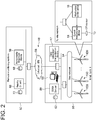
- FIG. 2 is a schematic diagram showing a configuration example of a wind farm 50 including a plurality of wind turbine power generating apparatuses 100 and a configuration example of a remote monitoring system 52.
- the wind farm 50 includes a plurality of the above-described wind turbine power generating apparatuses 100, and each wind turbine power generating apparatus 100 is provided with the wind turbine control device 16 and a current measurement device 14 which will be described later.
- the wind turbine control device 16 and the current measurement device 14 are connected to the remote monitoring system 52 via the communication network 48.
- the communication network 48 includes a site network 54 provided in the wind farm 50.
- the site network 54 is connected to the remote monitoring system 52 via an Internet virtual private network (VPN) 56.
- VPN Internet virtual private network
- the site network 54 is connected to a data collection/transmission device 17, a SCADA server 58, and a computer 60.
- the SCADA server 58 is connected to a storage device 62.
- the remote monitoring system 52 includes an abnormality diagnosis device 18 and a remote client 66.
- the abnormality diagnosis device 18 is connected to a storage device 68, and the remote client 66 is connected to a storage device 70.
- FIG. 3 is a schematic diagram showing a configuration example of a condition monitoring device 2 according to an embodiment.
- the condition monitoring device 2 is a device for a wind turbine power generating apparatus and is configured to monitor the condition of the auxiliary system 4 of the above-described wind turbine power generating apparatus 100.
- the auxiliary system 4 includes a plurality of the above-described auxiliary motors 6, and an auxiliary motor power supply system 8 for supplying power to the plurality of auxiliary motors 6.
- the plurality of auxiliary motors 6 will be described without distinguishing the type of the auxiliary motors 6 (cooling fan motor 6A, lubricating oil pump motor 6B, control oil pump motor 6C, pitch motor 6D, yaw motor 6E, cooling fan motor 6F).
- the plurality of auxiliary motors 6 may include an auxiliary motor other than the auxiliary motors 6A to 6F.
- the auxiliary motor power supply system 8 includes a power-supply-side line 10 connected to a power supply (not shown) and a plurality of auxiliary-motor-side lines 12 diverging from the power-supply-side line 10 and connected to the plurality of auxiliary motors 6, respectively.
- the power-supply-side line 10 is provided with a breaker 9, and each of the auxiliary-motor-side lines 12 is provided with a contactor 5.
- the condition monitoring device 2 includes a current transducer (CT) sensor 13 as a current sensor disposed on the power-supply-side line 10, the current measurement device 14 configured to measure a current flowing through the power-supply-side line 10 based on the output of the CT sensor 13, the wind turbine control device 16 for controlling the plurality of auxiliary motors 6, the data collection/transmission device 17, and the abnormality diagnosis device 18.
- CT current transducer
- the wind turbine control device 16 is configured to, when the generator 3 of the wind turbine power generating apparatus 100 is in a standby state where power generation is stopped at a low wind speed, execute a single sequential operation mode in which each of the plurality of auxiliary motors 6 is singly and sequentially operated.
- the wind turbine control device 16 controls each of the auxiliary motors 6 by controlling the opening and closing of each of the contactors 5.
- the "standby state where power generation is stopped at a low wind speed” means that power generation by the generator 3 is stopped since the wind speed measured by a wind speed meter 15 is lower than the cut-in wind speed (threshold of wind speed for the generator 3 to start power generation) although the wind turbine rotor 36 is rotating.
- “singly operated” means that the operating period of one auxiliary motor 6 does not overlap the operating period of another auxiliary motor 6.
- the current measurement device 14 is configured to measure a current flowing through the power-supply-side line 10 during execution of the single sequential operation mode by the wind turbine control device 16, based on the output of the CT sensor 13.
- the current measurement device is configured to acquire a waveform of a three-phase alternating current for driving the auxiliary motors 6 by high-speed sampling.
- the abnormality diagnosis device 18 is configured to perform abnormality diagnosis of the auxiliary system 4, based on the measurement result of the current measurement device 14.
- the abnormality diagnosis device 18 is configured to perform abnormality diagnosis of the auxiliary system 4 by applying fast Fourier transform (FFT) to the current measurement data acquired by the current measurement device 14 using the high-speed sampling.
- FFT fast Fourier transform
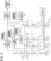
- FIG. 4 is a schematic configuration diagram of a condition monitoring device according to a comparative embodiment.
- the current measurement device 14 measures a current flowing through the power-supply-side line 10, so that the condition of the auxiliary system 4 including the plurality of auxiliary motors 6 can be grasped by a single CT sensor 13 and a single current measurement device 14. Therefore, compared with the case where the CT sensor 13 and the current measurement device 14 are provided for each auxiliary-motor-side line 12 as shown in FIG. 4 , it is possible to achieve a low-cost condition monitoring device 2 that can monitor the condition of the auxiliary system 4 of the wind turbine power generating apparatus 100 with a small number of components.
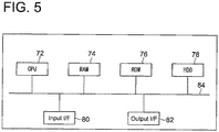
- FIG. 5 is a diagram showing an example of a hardware configuration of the current measurement device 14, the wind turbine control device 16, the data collection/transmission device 17, and the abnormality diagnosis device 18.
- the hardware configuration shown in FIG. 5 is provided by a computer including a central processing unit (CPU) 72, a random access memory (RAM) 74, a read only memory (ROM) 76, a hard disk drive (HDD) 78, an input I/F 80, and an output I/F 82, which are connected via a bus 84.
- Each of the current measurement device 14, the wind turbine control device 16, the data collection/transmission device 17, and the abnormality diagnosis device 18 is provided by executing a program that realizes each function by the computer.
- the function of each configuration described below is realized by, for instance, loading a program stored in the ROM 76 into the RAM 74 and executing the program by the CPU 72, and reading and writing data in the RAM 74 or the ROM 76.
- FIG. 6 is a schematic diagram showing an example of operation flowchart of each configuration of the condition monitoring device 2.
- the wind turbine control device 16 transmits a trigger signal to the current measurement device 14 to start the single sequential operation mode in which each of the auxiliary motors 6 is singly and sequentially operated for a predetermined time.
- n is the number of auxiliary motors 6 included in the auxiliary system 4
- the wind turbine control device 16 operates the auxiliary motors 6 sequentially and singly for a predetermined time in S11 to S1n.
- the first auxiliary motor 6 is operated alone for a predetermined time in S11
- the second auxiliary motor 6 is operated alone for a predetermined time in S12
- the third auxiliary motor 6 is operated alone for a predetermined time in S13
- the remaining auxiliary motors 6 are sequentially operated alone for predetermined times up to S1n. Then, the wind turbine control device 16 stops the trigger signal in S1f to end the single sequential operation mode.
- FIG. 7 is a timing chart showing a current measurement value of the power-supply-side line 10 measured by the current measurement device 14 and an operating period of each auxiliary motor 6 in the single sequential operation mode.
- the auxiliary motor 6 operated i-thly of the n auxiliary motors 6 in the single sequential operation mode is defined as the i-th auxiliary motor.
- i is an integer of 1 to n.
- time al is the timing at which the first auxiliary motor 6 is activated.
- the period from time a1 to time b1 is an inrush current period corresponding to the inrush current after activation of the first auxiliary motor 6.
- the period from time b1 to time c1 is a rated current period (second period) during which the rated current is applied to the first auxiliary motor 6.
- the period from time c1 to time d1 is a current decrease period during which the current flowing in the first auxiliary motor 6 decreases between the rated current period of the first auxiliary motor 6 and time d1 at which the operation of the first auxiliary motor 6 is stopped.
- time ai is the timing at which the i-th auxiliary motor 6 is activated.
- the period from time ai to time bi is an inrush current period corresponding to the inrush current after activation of the i-th auxiliary motor 6.
- the period from time bi to time ci is a rated current period (second period) during which the rated current is applied to the i-th auxiliary motor 6.
- the period from time ci to time di is a current decrease period during which the current flowing in the i-th auxiliary motor 6 decreases between the rated current period of the i-th auxiliary motor 6 and time di at which the operation of the i-th auxiliary motor 6 is stopped.
- the wind turbine control device 16 is configured to sequentially and singly operate each of the auxiliary motors 6 at a predetermined timing (time) based on the trigger signal. In other words, the wind turbine control device 16 is configured to sequentially activate and stop each of the auxiliary motors 6 at a predetermined timing based on the trigger signal.
- the current measurement device 14 starts the measurement of a current flowing through the power-supply-side line 10 in response to receipt of the trigger signal from the wind turbine control device 16. Then, in S22, the current measurement device 14 stops the measurement of a current flowing through the power-supply-side line 10 when the trigger signal transmitted from the wind turbine control device 16 is stopped. That is, as shown in FIG. 7 , the current measurement device 14 measures a current flowing through the power-supply-side line 10 based on the output of the CT sensor 13 over a period from the start time 0 of the trigger signal to the stop time e of the trigger signal during execution of the single sequential operation mode.
- the measurement result of the current measurement device 14 of each wind turbine power generating apparatus 100 (measurement data indicating the measurement value of a current flowing through the power-supply-side line 10 in the single sequential operation mode) is transmitted to the abnormality diagnosis device 18 via the site network 54, the data collection/transmission device 17, and the Internet VPN 56.
- the abnormality diagnosis device 18 extracts, from the current measurement data of the power-supply-side line 10 measured by the current measurement device 14 during execution of the single sequential operation mode, current measurement data of the power-supply-side line 10 for at least a part of the operating period of each auxiliary motor 6.
- the abnormality diagnosis device 18 extracts, from the current measurement data Dt of the power-supply-side line 10 measured by the current measurement device 14 during execution of the single sequential operation mode, current measurement data D1 for the rated current period (period from time b1 to time c1) during which the rated current is applied to the first auxiliary motor 6.
- the abnormality diagnosis device 18 extracts, from the current measurement data Dt measured by the current measurement device 14 during execution of the single sequential operation mode, current measurement data D1 for the rated current period (period from time b1 to time c1) during which the rated current is applied to the first auxiliary motor 6, excluding current measurement data for the first period (period from time 0 to time a1) from start of the trigger signal to activation of the first auxiliary motor 6 and current measurement data for the inrush current period (period from a1 to b1) corresponding to the inrush current after activation of the first auxiliary motor.
- the abnormality diagnosis device 18 extracts, from the current measurement data Dt of the power-supply-side line measured by the current measurement device 14 during execution of the single sequential operation mode, current measurement data Di for the rated current period (period from time bi to time ci) during which the rated current is applied to the i-th auxiliary motor 6.
- the abnormality diagnosis device 18 extracts, from the current measurement data Dt measured by the current measurement device 14 during execution of the single sequential operation mode, current measurement data Di for the rated current period (period from time bi to time ci) during which the rated current is applied to the i-th auxiliary motor 6, excluding current measurement data for the first period (period from time 0 to time ai) from start of the trigger signal to activation of the i-th auxiliary motor 6 and current measurement data for the inrush current period (period from ai to bi) corresponding to the inrush current after activation of the i-th auxiliary motor.
- the length of the first period (period from time 0 to time ai) from start of the trigger signal to activation of the i-th auxiliary motor 6 may be, for example, 1 to 5 seconds, and the length of the rated current period (period from time bi to time ci) during which the rated current is applied to the i-th auxiliary motor 6 may be, for example, 2 to 15 seconds.
- the abnormality diagnosis device 18 performs abnormality diagnosis of the i-th auxiliary motor 6 and a rotary machine (e.g., drive transmission device such as belt or gear of gear box 42, bearing 34, or other rotary machines) connected to the i-th auxiliary motor 6, based on the measurement data Di of the i-th auxiliary motor 6 extracted in S31.
- a rotary machine e.g., drive transmission device such as belt or gear of gear box 42, bearing 34, or other rotary machines
- the abnormality diagnosis device 18 performs at least one of harmonic analysis, sideband analysis, pattern analysis of transient current values, or distortion analysis on the measurement data Di of the i-th auxiliary motor 6 measured by the current measurement device 14, and performs abnormality diagnosis of the i-th auxiliary motor 6 and the rotary machine connected to the i-th auxiliary motor, based on a feature extracted from the measurement data Di. Then, in S33, the diagnosis result of the abnormality diagnosis device 18 is displayed on a display device (not shown).
- the abnormality diagnosis device 18 configured to perform abnormality diagnosis of the auxiliary motor 6 and the rotary machine connected to the auxiliary motor 6 based on the trigger signal and the current measurement data Dt which is the measurement result of the current measurement device 14, it is possible to perform abnormality diagnosis of the auxiliary system 4 with a low-cost configuration of a small number of components.
- abnormality diagnosis is performed based on the current measurement data Di for at least a part of the rated current period during which the rated current is applied to the auxiliary motor 6, it is possible to accurately perform abnormality diagnosis with a low-cost configuration of a small number of components.
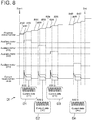
- FIG. 8 is a timing chart showing a current measurement value of the power-supply-side line 10 measured by the current measurement device 14 and an operating period of each auxiliary motor in the single sequential operation mode according to another embodiment.
- the wind turbine control device 16 is configured to operate singly and sequentially each of the auxiliary motors 6 in the single sequential operation mode, according to a progress status number indicating the progress status of the single sequential operation mode
- the abnormality diagnosis device 18 is configured to acquire the current measurement data Dt measured by the current measurement device 14 chronologically in association with the progress status number, and perform abnormality diagnosis of the auxiliary system 4, based on the current measurement data Dt and the progress status number.
- the progress status number 100 indicates the status of the period from start of the single sequential operation mode to activation of the first auxiliary motor 6.
- the progress status number 101 indicates the status of the inrush current period corresponding to the inrush current after activation of the first auxiliary motor.
- the progress status number 102 indicates the status of the rated current period during which the rated current is applied to the first auxiliary motor 6.
- the progress status number i00 indicates the status of the period from start of the single sequential operation mode to activation of the i-th auxiliary motor 6.
- the progress status number i01 indicates the status of the inrush current period (third period) corresponding to the inrush current after activation of the i-th auxiliary motor.
- the progress status number i02 indicates the status of the rated current period during which the rated current is applied to the i-th auxiliary motor 6.
- the length of the rated current period may be, for example, 2 to 15 seconds.
- the abnormality diagnosis device 18 extracts, from the current measurement data Dt of the power-supply-side line measured by the current measurement device 14 during execution of the single sequential operation mode, current measurement data Di for the rated current period during which the rated current is applied to the i-th auxiliary motor 6, based on the progress status number.
- the abnormality diagnosis device 18 extracts, from the current measurement data Dt of the power-supply-side line measured by the current measurement device 14 during execution of the single sequential operation mode, current measurement data D1 associated with the progress status number i02.
- the abnormality diagnosis device 18 performs abnormality diagnosis of the i-th auxiliary motor 6 and the rotary machine connected to the i-th auxiliary motor, based on the extracted measurement data Di of the i-th auxiliary motor.
- the abnormality diagnosis device 18 performs at least one of harmonic analysis, sideband analysis, pattern analysis of transient current values, or distortion analysis on the measurement data Di of the i-th auxiliary motor 6 measured by the current measurement device 14, and performs abnormality diagnosis of the i-th auxiliary motor 6 and the rotary machine connected to the i-th auxiliary motor, based on a feature extracted from the measurement data Di.
- the progress status number includes, for each auxiliary motor 6, a progress status number corresponding to the rated current period during which the rated current is applied to the auxiliary motor 6, and the abnormality diagnosis device 18 is configured to perform, based on the current measurement data Di associated with the progress status number corresponding to the rated current period among the current measurement data Dt measured during execution of the single sequential operation mode, abnormality diagnosis of the auxiliary motor 6 corresponding to the progress status number and the rotary machine connected to the auxiliary motor 6.
- the current measurement data Di for a period necessary for abnormality diagnosis of the auxiliary system 4 can be extracted based on the progress status number. Accordingly, when abnormality diagnosis of the auxiliary system 4 is performed based on the progress status number and the current measurement data Dt measured by the current measurement device 14, it is possible to perform abnormality diagnosis of the auxiliary system 4 with a low-cost configuration of a small number of components.
- the CT sensor 13 (CT current sensor) has been described as the current sensor disposed on the power-supply-side line 10.
- the current sensor disposed on the power-supply-side line 10 is not limited to the CT current sensor.
- Various current sensors such as a Hall sensor, a Rogoski sensor, and a flux sensor can be used.
- abnormality diagnosis of the i-th auxiliary motor 6 and the rotary machine connected to the i-th auxiliary motor 6 is performed based on the current measurement data Di measured during the rated current period of the i-th auxiliary motor 6 by the current measurement device 14.
- abnormality diagnosis may be performed based on current measurement data measured for at least a part of the rated current period of the i-th auxiliary motor 6.
- abnormality diagnosis of the i-th auxiliary motor 6 and the rotary machine connected to the i-th auxiliary motor 6 may be performed based on current measurement data for at least a part of the operating period of the i-th auxiliary motor 6 in the single sequential operation mode.
- abnormality diagnosis of the auxiliary motor 6 and the rotary machine connected to the auxiliary motor 6 is performed, but only one of the auxiliary motor 6 or the rotary machine may be diagnosed.
- the target of abnormality diagnosis of the abnormality diagnosis device 18 may be at least one of the auxiliary motor 6 or the rotary machine connected to the auxiliary motor 6.
- the target of abnormality diagnosis of the abnormality diagnosis device 18 may be the auxiliary motor power supply system 8 of the auxiliary system 4.
- the single sequential operation mode is executed when the generator 3 is in a standby state where power generation is stopped at a low wind speed.
- the wind turbine control device 16 may count the number of times the generator 3 is in the standby state where power generation is stopped at a low wind speed, and may execute the single sequential operation mode periodically (for example, when the number of standby times is an integral multiple of a predetermined number), based on the counted number.
- the current measurement device measures a current flowing through the power-supply-side line, so that the condition of the auxiliary system including the plurality of auxiliary motors can be grasped based on the measurement result of the single current measurement device. Therefore, compared with the case where the current measurement device is provided for each auxiliary-motor-side line, it is possible to monitor the condition of the auxiliary system of the wind turbine power generating apparatus with a small number of components.
Landscapes
- Engineering & Computer Science (AREA)
- Sustainable Development (AREA)
- Sustainable Energy (AREA)
- Chemical & Material Sciences (AREA)
- Combustion & Propulsion (AREA)
- Mechanical Engineering (AREA)
- General Engineering & Computer Science (AREA)
- Life Sciences & Earth Sciences (AREA)
- Physics & Mathematics (AREA)
- General Physics & Mathematics (AREA)
- Power Engineering (AREA)
- Fluid Mechanics (AREA)
- Wind Motors (AREA)
- Testing Of Devices, Machine Parts, Or Other Structures Thereof (AREA)
- Control Of Eletrric Generators (AREA)
- Control Of Multiple Motors (AREA)
Abstract
Description
- The present disclosure relates to a condition monitoring device and a condition monitoring method for a wind turbine power generating apparatus.
-
Patent Document 1 discloses an abnormality diagnosis method for performing abnormality diagnosis of a rotary machine including a motor, based on a reference sinusoidal signal waveform of a rated current of the motor. - Patent Document 1:
JP5733913B - The wind turbine power generating apparatus is provided with an auxiliary system including a plurality of auxiliary motors such as fan motors and pump motors and an auxiliary motor power supply system for supplying power to the plurality of auxiliary motors.
- If a current measurement device is separately provided for each of the auxiliary motors in order to monitor the condition of the auxiliary system, the number of components of the device for monitoring the condition increases, so that the cost increases. Further,
Patent Document 1 does not disclose specific knowledge regarding the condition monitoring of the auxiliary system of the wind turbine power generating apparatus. - In view of the above, an object of the present disclosure is to provide a condition monitoring device and a condition monitoring method for a wind turbine power generating apparatus whereby it is possible to monitor the condition of the auxiliary system of the wind turbine power generating apparatus with a small number of components.
- To accomplish the above object, a condition monitoring device for a wind turbine power generating apparatus according to an embodiment of the present disclosure for monitoring a condition of an auxiliary system of the wind turbine power generating apparatus is provided, the auxiliary system including a plurality of auxiliary motors and an auxiliary motor power supply system for supplying power to the plurality of auxiliary motors, the auxiliary motor power supply system including a power-supply-side line connected to a power supply and a plurality of auxiliary-motor-side lines diverging from the power-supply-side line and connected to the plurality of auxiliary motors respectively, the condition monitoring device comprises: a current measurement device for measuring a current flowing through the power-supply-side line; and a control device for controlling the plurality of auxiliary motors. The control device is configured to, when a generator of the wind turbine power generating apparatus is in a standby state where power generation is stopped at a low wind speed, execute a single sequential operation mode in which each of the plurality of auxiliary motors is singly and sequentially operated. The current measurement device is configured to measure a current flowing through the power-supply-side line during execution of the single sequential operation mode by the control device.
- To accomplish the above object, a condition monitoring method for a wind turbine power generating apparatus according to an embodiment of the present disclosure for monitoring a condition of an auxiliary system of the wind turbine power generating apparatus is provided, the auxiliary system including a plurality of auxiliary motors and an auxiliary motor power supply system for supplying power to the plurality of auxiliary motors, the auxiliary motor power supply system including a power-supply-side line connected to a power supply and a plurality of auxiliary-motor-side lines diverging from the power-supply-side line and connected to the plurality of auxiliary motors respectively, the condition monitoring method comprises: a step of, when a generator of the wind turbine power generating apparatus is in a standby state where power generation is stopped at a low wind speed, executing a single sequential operation mode in which each of the plurality of auxiliary motors is singly and sequentially operated; and a step of measuring a current flowing through the power-supply-side line during execution of the single sequential operation mode.
- The present disclosure provides a condition monitoring device and a condition monitoring method for a wind turbine power generating apparatus whereby it is possible to monitor the condition of the auxiliary system of the wind turbine power generating apparatus with a small number of components.
-
-
FIG. 1 is a schematic diagram showing a configuration example of a wind turbinepower generating apparatus 100. -
FIG. 2 is a schematic diagram showing a configuration example of awind farm 50 including a plurality of wind turbinepower generating apparatuses 100 and a configuration example of aremote monitoring system 52. -
FIG. 3 is a schematic diagram showing a configuration example of acondition monitoring device 2 according to an embodiment. -
FIG. 4 is a schematic configuration diagram of a condition monitoring device according to a comparative embodiment. -
FIG. 5 is a diagram showing an example of a hardware configuration of acurrent measurement device 14, a windturbine control device 16, a data collection/transmission device 17, and anabnormality diagnosis device 18. -
FIG. 6 is a schematic diagram showing an example of operation flowchart of each configuration of thecondition monitoring device 2. -
FIG. 7 is a timing chart showing a current measurement value of a power-supply-side line 10 measured by thecurrent measurement device 14 and an operating period of each auxiliary motor in the single sequential operation mode. -
FIG. 8 is a timing chart showing a current measurement value of a power-supply-side line 10 measured by thecurrent measurement device 14 and an operating period of each auxiliary motor in the single sequential operation mode according to another embodiment. - Embodiments of the present disclosure will now be described in detail with reference to the accompanying drawings. It is intended, however, that unless particularly specified, dimensions, materials, shapes, relative positions and the like of components described in the embodiments shall be interpreted as illustrative only and not intended to limit the scope of the present invention.
- For instance, an expression of relative or absolute arrangement such as "in a direction", "along a direction", "parallel", "orthogonal", "centered", "concentric" and "coaxial" shall not be construed as indicating only the arrangement in a strict literal sense, but also includes a state where the arrangement is relatively displaced by a tolerance, or by an angle or a distance whereby it is possible to achieve the same function.
- For instance, an expression of an equal state such as "same" "equal" and "uniform" shall not be construed as indicating only the state in which the feature is strictly equal, but also includes a state in which there is a tolerance or a difference that can still achieve the same function.
- Further, for instance, an expression of a shape such as a rectangular shape or a cylindrical shape shall not be construed as only the geometrically strict shape, but also includes a shape with unevenness or chamfered corners within the range in which the same effect can be achieved.
- On the other hand, an expression such as "comprise", "include", "have", "contain" and "constitute" are not intended to be exclusive of other components.
-
FIG. 1 is a schematic diagram showing a configuration example of a wind turbine power generating apparatus 100 (hereinafter, also referred to as "wind turbine") to be monitored by a condition monitoring device, which will be described later. - The wind turbine
power generating apparatus 100 includes atower 30, anacelle 32 disposed on top of thetower 30, awind turbine rotor 36 rotatably supported by abearing 34 disposed on thenacelle 32, agenerator 3 as a main machine accommodated in thenacelle 32, anauxiliary system 4, and a windturbine control device 16. - The
wind turbine rotor 36 includes amain shaft 39 rotatably supported by thebearing 34, ahub 38 connected to one end of themain shaft 39, and a plurality ofwind turbine blades 40 attached to the outer peripheral side of thehub 38. Themain shaft 39 is connected to thegenerator 3 via agear box 42 so that rotational energy of thewind turbine rotor 36 is transmitted to thegenerator 3 via thegear box 42. - The
auxiliary system 4 includes a plurality ofauxiliary motors 6. Eachauxiliary motor 6 is a motor that functions as an accessory device necessary for operating thegenerator 3 as the main machine. The plurality ofauxiliary motors 6 includes, for example, acooling fan motor 6A for cooling the inside of thegenerator 3, a lubricatingoil pump motor 6B disposed on a lubricating oil circuit for supplying lubricating oil to at least one of thegear box 42 or thebearing 34, a controloil pump motor 6C disposed on a control oil circuit for supplying control oil to a device driven by the control oil, apitch motor 6D for adjusting the pitch angle of thewind turbine blade 40, ayaw motor 6E for adjusting the yaw angle of thenacelle 32, and acooling fan motor 6F used in a cooling mechanism for cooling devices which require cooling. - The wind
turbine control device 16 is configured to control each of the plurality of auxiliary motors 6 (6A to 6F), and is configured to be able to communicate with anoperation terminal 44 arranged in thetower 30 and a supervision control and data acquisition (SCADA)system 46 arranged separately from the wind turbinepower generating apparatus 100 via acommunication network 48. -
FIG. 2 is a schematic diagram showing a configuration example of awind farm 50 including a plurality of wind turbinepower generating apparatuses 100 and a configuration example of aremote monitoring system 52. - As shown in
FIG. 2 , thewind farm 50 includes a plurality of the above-described wind turbinepower generating apparatuses 100, and each wind turbinepower generating apparatus 100 is provided with the windturbine control device 16 and acurrent measurement device 14 which will be described later. The windturbine control device 16 and thecurrent measurement device 14 are connected to theremote monitoring system 52 via thecommunication network 48. - In the exemplary embodiment shown in
FIG. 2 , thecommunication network 48 includes asite network 54 provided in thewind farm 50. Thesite network 54 is connected to theremote monitoring system 52 via an Internet virtual private network (VPN) 56. - The
site network 54 is connected to a data collection/transmission device 17, a SCADAserver 58, and acomputer 60. The SCADAserver 58 is connected to astorage device 62. - The
remote monitoring system 52 includes anabnormality diagnosis device 18 and aremote client 66. Theabnormality diagnosis device 18 is connected to astorage device 68, and theremote client 66 is connected to astorage device 70. -
FIG. 3 is a schematic diagram showing a configuration example of acondition monitoring device 2 according to an embodiment. Thecondition monitoring device 2 is a device for a wind turbine power generating apparatus and is configured to monitor the condition of theauxiliary system 4 of the above-described wind turbinepower generating apparatus 100. - The
auxiliary system 4 includes a plurality of the above-describedauxiliary motors 6, and an auxiliary motorpower supply system 8 for supplying power to the plurality ofauxiliary motors 6. In the following, the plurality ofauxiliary motors 6 will be described without distinguishing the type of the auxiliary motors 6 (cooling fan motor 6A, lubricatingoil pump motor 6B, controloil pump motor 6C,pitch motor 6D,yaw motor 6E,cooling fan motor 6F). The plurality ofauxiliary motors 6 may include an auxiliary motor other than theauxiliary motors 6A to 6F. - The auxiliary motor
power supply system 8 includes a power-supply-side line 10 connected to a power supply (not shown) and a plurality of auxiliary-motor-side lines 12 diverging from the power-supply-side line 10 and connected to the plurality ofauxiliary motors 6, respectively. The power-supply-side line 10 is provided with abreaker 9, and each of the auxiliary-motor-side lines 12 is provided with acontactor 5. - The
condition monitoring device 2 includes a current transducer (CT)sensor 13 as a current sensor disposed on the power-supply-side line 10, thecurrent measurement device 14 configured to measure a current flowing through the power-supply-side line 10 based on the output of theCT sensor 13, the windturbine control device 16 for controlling the plurality ofauxiliary motors 6, the data collection/transmission device 17, and theabnormality diagnosis device 18. - The wind
turbine control device 16 is configured to, when thegenerator 3 of the wind turbinepower generating apparatus 100 is in a standby state where power generation is stopped at a low wind speed, execute a single sequential operation mode in which each of the plurality ofauxiliary motors 6 is singly and sequentially operated. In the illustrated exemplary embodiment, the windturbine control device 16 controls each of theauxiliary motors 6 by controlling the opening and closing of each of thecontactors 5. The "standby state where power generation is stopped at a low wind speed" means that power generation by thegenerator 3 is stopped since the wind speed measured by awind speed meter 15 is lower than the cut-in wind speed (threshold of wind speed for thegenerator 3 to start power generation) although thewind turbine rotor 36 is rotating. Further, "singly operated" means that the operating period of oneauxiliary motor 6 does not overlap the operating period of anotherauxiliary motor 6. - The
current measurement device 14 is configured to measure a current flowing through the power-supply-side line 10 during execution of the single sequential operation mode by the windturbine control device 16, based on the output of theCT sensor 13. The current measurement device is configured to acquire a waveform of a three-phase alternating current for driving theauxiliary motors 6 by high-speed sampling. Theabnormality diagnosis device 18 is configured to perform abnormality diagnosis of theauxiliary system 4, based on the measurement result of thecurrent measurement device 14. Theabnormality diagnosis device 18 is configured to perform abnormality diagnosis of theauxiliary system 4 by applying fast Fourier transform (FFT) to the current measurement data acquired by thecurrent measurement device 14 using the high-speed sampling. - The main effects of the
condition monitoring device 2 shown inFIG. 3 will now be described in comparison with a comparative embodiment shown inFIG. 4. FIG. 4 is a schematic configuration diagram of a condition monitoring device according to a comparative embodiment. - According to the configuration shown in
FIG. 3 , during execution of the single operation mode, thecurrent measurement device 14 measures a current flowing through the power-supply-side line 10, so that the condition of theauxiliary system 4 including the plurality ofauxiliary motors 6 can be grasped by asingle CT sensor 13 and a singlecurrent measurement device 14. Therefore, compared with the case where theCT sensor 13 and thecurrent measurement device 14 are provided for each auxiliary-motor-side line 12 as shown inFIG. 4 , it is possible to achieve a low-costcondition monitoring device 2 that can monitor the condition of theauxiliary system 4 of the wind turbinepower generating apparatus 100 with a small number of components. -
FIG. 5 is a diagram showing an example of a hardware configuration of thecurrent measurement device 14, the windturbine control device 16, the data collection/transmission device 17, and theabnormality diagnosis device 18. The hardware configuration shown inFIG. 5 is provided by a computer including a central processing unit (CPU) 72, a random access memory (RAM) 74, a read only memory (ROM) 76, a hard disk drive (HDD) 78, an input I/F 80, and an output I/F 82, which are connected via abus 84. Each of thecurrent measurement device 14, the windturbine control device 16, the data collection/transmission device 17, and theabnormality diagnosis device 18 is provided by executing a program that realizes each function by the computer. The function of each configuration described below is realized by, for instance, loading a program stored in theROM 76 into theRAM 74 and executing the program by theCPU 72, and reading and writing data in theRAM 74 or theROM 76. -
FIG. 6 is a schematic diagram showing an example of operation flowchart of each configuration of thecondition monitoring device 2. - As shown in
FIG. 6 , in S10, the windturbine control device 16 transmits a trigger signal to thecurrent measurement device 14 to start the single sequential operation mode in which each of theauxiliary motors 6 is singly and sequentially operated for a predetermined time. Here, assuming that n is the number ofauxiliary motors 6 included in theauxiliary system 4, the windturbine control device 16 operates theauxiliary motors 6 sequentially and singly for a predetermined time in S11 to S1n. Specifically, the firstauxiliary motor 6 is operated alone for a predetermined time in S11, the secondauxiliary motor 6 is operated alone for a predetermined time in S12, the thirdauxiliary motor 6 is operated alone for a predetermined time in S13, and likewise the remainingauxiliary motors 6 are sequentially operated alone for predetermined times up to S1n. Then, the windturbine control device 16 stops the trigger signal in S1f to end the single sequential operation mode. -
FIG. 7 is a timing chart showing a current measurement value of the power-supply-side line 10 measured by thecurrent measurement device 14 and an operating period of eachauxiliary motor 6 in the single sequential operation mode. As shown inFIG. 7 , theauxiliary motor 6 operated i-thly of the nauxiliary motors 6 in the single sequential operation mode is defined as the i-th auxiliary motor. i is an integer of 1 to n. - As shown in
FIG. 7 , in the single sequential operation mode, when the start time of the trigger signal is 0, the firstauxiliary motor 6 operates from time al to time d1. InFIG. 7 , time al is the timing at which the firstauxiliary motor 6 is activated. The period from time a1 to time b1 is an inrush current period corresponding to the inrush current after activation of the firstauxiliary motor 6. The period from time b1 to time c1 is a rated current period (second period) during which the rated current is applied to the firstauxiliary motor 6. The period from time c1 to time d1 is a current decrease period during which the current flowing in the firstauxiliary motor 6 decreases between the rated current period of the firstauxiliary motor 6 and time d1 at which the operation of the firstauxiliary motor 6 is stopped. - The same applies to the operation of the second and subsequent
auxiliary motors 6. Specifically, when the start time of the trigger signal is 0, the i-thauxiliary motor 6 operates from time ai to time di. InFIG. 7 , time ai is the timing at which the i-thauxiliary motor 6 is activated. The period from time ai to time bi is an inrush current period corresponding to the inrush current after activation of the i-thauxiliary motor 6. The period from time bi to time ci is a rated current period (second period) during which the rated current is applied to the i-thauxiliary motor 6. The period from time ci to time di is a current decrease period during which the current flowing in the i-thauxiliary motor 6 decreases between the rated current period of the i-thauxiliary motor 6 and time di at which the operation of the i-thauxiliary motor 6 is stopped. - In this way, the wind
turbine control device 16 is configured to sequentially and singly operate each of theauxiliary motors 6 at a predetermined timing (time) based on the trigger signal. In other words, the windturbine control device 16 is configured to sequentially activate and stop each of theauxiliary motors 6 at a predetermined timing based on the trigger signal. - Referring to
FIG. 6 again, in S21, thecurrent measurement device 14 starts the measurement of a current flowing through the power-supply-side line 10 in response to receipt of the trigger signal from the windturbine control device 16. Then, in S22, thecurrent measurement device 14 stops the measurement of a current flowing through the power-supply-side line 10 when the trigger signal transmitted from the windturbine control device 16 is stopped. That is, as shown inFIG. 7 , thecurrent measurement device 14 measures a current flowing through the power-supply-side line 10 based on the output of theCT sensor 13 over a period from thestart time 0 of the trigger signal to the stop time e of the trigger signal during execution of the single sequential operation mode. - Further, as shown in S23 of
FIG. 6 , the measurement result of thecurrent measurement device 14 of each wind turbine power generating apparatus 100 (measurement data indicating the measurement value of a current flowing through the power-supply-side line 10 in the single sequential operation mode) is transmitted to theabnormality diagnosis device 18 via thesite network 54, the data collection/transmission device 17, and theInternet VPN 56. - Then, in S31, the
abnormality diagnosis device 18 extracts, from the current measurement data of the power-supply-side line 10 measured by thecurrent measurement device 14 during execution of the single sequential operation mode, current measurement data of the power-supply-side line 10 for at least a part of the operating period of eachauxiliary motor 6. - The process of S31 will now be described in detail with reference to
FIG. 7 . - In the example shown in
FIG. 7 , theabnormality diagnosis device 18 extracts, from the current measurement data Dt of the power-supply-side line 10 measured by thecurrent measurement device 14 during execution of the single sequential operation mode, current measurement data D1 for the rated current period (period from time b1 to time c1) during which the rated current is applied to the firstauxiliary motor 6. More specifically, theabnormality diagnosis device 18 extracts, from the current measurement data Dt measured by thecurrent measurement device 14 during execution of the single sequential operation mode, current measurement data D1 for the rated current period (period from time b1 to time c1) during which the rated current is applied to the firstauxiliary motor 6, excluding current measurement data for the first period (period fromtime 0 to time a1) from start of the trigger signal to activation of the firstauxiliary motor 6 and current measurement data for the inrush current period (period from a1 to b1) corresponding to the inrush current after activation of the first auxiliary motor. - The same applies to the operation of the second and subsequent
auxiliary motors 6. Specifically, theabnormality diagnosis device 18 extracts, from the current measurement data Dt of the power-supply-side line measured by thecurrent measurement device 14 during execution of the single sequential operation mode, current measurement data Di for the rated current period (period from time bi to time ci) during which the rated current is applied to the i-thauxiliary motor 6. More specifically, theabnormality diagnosis device 18 extracts, from the current measurement data Dt measured by thecurrent measurement device 14 during execution of the single sequential operation mode, current measurement data Di for the rated current period (period from time bi to time ci) during which the rated current is applied to the i-thauxiliary motor 6, excluding current measurement data for the first period (period fromtime 0 to time ai) from start of the trigger signal to activation of the i-thauxiliary motor 6 and current measurement data for the inrush current period (period from ai to bi) corresponding to the inrush current after activation of the i-th auxiliary motor. The length of the first period (period fromtime 0 to time ai) from start of the trigger signal to activation of the i-thauxiliary motor 6 may be, for example, 1 to 5 seconds, and the length of the rated current period (period from time bi to time ci) during which the rated current is applied to the i-thauxiliary motor 6 may be, for example, 2 to 15 seconds. - Then, in S32 shown in
FIG. 6 , theabnormality diagnosis device 18 performs abnormality diagnosis of the i-thauxiliary motor 6 and a rotary machine (e.g., drive transmission device such as belt or gear ofgear box 42, bearing 34, or other rotary machines) connected to the i-thauxiliary motor 6, based on the measurement data Di of the i-thauxiliary motor 6 extracted in S31. Theabnormality diagnosis device 18 performs at least one of harmonic analysis, sideband analysis, pattern analysis of transient current values, or distortion analysis on the measurement data Di of the i-thauxiliary motor 6 measured by thecurrent measurement device 14, and performs abnormality diagnosis of the i-thauxiliary motor 6 and the rotary machine connected to the i-th auxiliary motor, based on a feature extracted from the measurement data Di. Then, in S33, the diagnosis result of theabnormality diagnosis device 18 is displayed on a display device (not shown). - As described above, in the single sequential operation mode, since each of the
auxiliary motors 6 is sequentially activated at a predetermined timing for eachauxiliary motor 6 based on the trigger signal, the current measurement data Di for a period necessary for abnormality diagnosis of theauxiliary system 4 can be extracted based on the trigger signal. Accordingly, with theabnormality diagnosis device 18 configured to perform abnormality diagnosis of theauxiliary motor 6 and the rotary machine connected to theauxiliary motor 6 based on the trigger signal and the current measurement data Dt which is the measurement result of thecurrent measurement device 14, it is possible to perform abnormality diagnosis of theauxiliary system 4 with a low-cost configuration of a small number of components. - Further, in the single sequential operation mode, since abnormality diagnosis of the
auxiliary motor 6 and the rotary machine connected to theauxiliary motor 6 is performed based on the current measurement data Di for at least a part of the period excluding the inrush current period, it is possible to accurately perform abnormality diagnosis with a low-cost configuration of a small number of components. - Further, since abnormality diagnosis is performed based on the current measurement data Di for at least a part of the rated current period during which the rated current is applied to the
auxiliary motor 6, it is possible to accurately perform abnormality diagnosis with a low-cost configuration of a small number of components. - Other embodiments will now be described.
-
FIG. 8 is a timing chart showing a current measurement value of the power-supply-side line 10 measured by thecurrent measurement device 14 and an operating period of each auxiliary motor in the single sequential operation mode according to another embodiment. - In the embodiment shown in
FIG. 8 , the windturbine control device 16 is configured to operate singly and sequentially each of theauxiliary motors 6 in the single sequential operation mode, according to a progress status number indicating the progress status of the single sequential operation mode, and theabnormality diagnosis device 18 is configured to acquire the current measurement data Dt measured by thecurrent measurement device 14 chronologically in association with the progress status number, and perform abnormality diagnosis of theauxiliary system 4, based on the current measurement data Dt and the progress status number. - In
FIG. 8 , theprogress status number 100 indicates the status of the period from start of the single sequential operation mode to activation of the firstauxiliary motor 6. Theprogress status number 101 indicates the status of the inrush current period corresponding to the inrush current after activation of the first auxiliary motor. Theprogress status number 102 indicates the status of the rated current period during which the rated current is applied to the firstauxiliary motor 6. - The same applies to the second and subsequent
auxiliary motors 6. Specifically, the progress status number i00 indicates the status of the period from start of the single sequential operation mode to activation of the i-thauxiliary motor 6. The progress status number i01 indicates the status of the inrush current period (third period) corresponding to the inrush current after activation of the i-th auxiliary motor. The progress status number i02 indicates the status of the rated current period during which the rated current is applied to the i-thauxiliary motor 6. The length of the rated current period may be, for example, 2 to 15 seconds. - The
abnormality diagnosis device 18 extracts, from the current measurement data Dt of the power-supply-side line measured by thecurrent measurement device 14 during execution of the single sequential operation mode, current measurement data Di for the rated current period during which the rated current is applied to the i-thauxiliary motor 6, based on the progress status number. In the example shown inFIG. 8 , theabnormality diagnosis device 18 extracts, from the current measurement data Dt of the power-supply-side line measured by thecurrent measurement device 14 during execution of the single sequential operation mode, current measurement data D1 associated with the progress status number i02. - Then, the
abnormality diagnosis device 18 performs abnormality diagnosis of the i-thauxiliary motor 6 and the rotary machine connected to the i-th auxiliary motor, based on the extracted measurement data Di of the i-th auxiliary motor. Theabnormality diagnosis device 18 performs at least one of harmonic analysis, sideband analysis, pattern analysis of transient current values, or distortion analysis on the measurement data Di of the i-thauxiliary motor 6 measured by thecurrent measurement device 14, and performs abnormality diagnosis of the i-thauxiliary motor 6 and the rotary machine connected to the i-th auxiliary motor, based on a feature extracted from the measurement data Di. - As described above, in the embodiment shown in
FIG. 8 , the progress status number includes, for eachauxiliary motor 6, a progress status number corresponding to the rated current period during which the rated current is applied to theauxiliary motor 6, and theabnormality diagnosis device 18 is configured to perform, based on the current measurement data Di associated with the progress status number corresponding to the rated current period among the current measurement data Dt measured during execution of the single sequential operation mode, abnormality diagnosis of theauxiliary motor 6 corresponding to the progress status number and the rotary machine connected to theauxiliary motor 6. - In the embodiment shown in
FIG. 8 , in the single sequential operation mode, since each of theauxiliary motors 6 is sequentially activated according to the progress status number, the current measurement data Di for a period necessary for abnormality diagnosis of theauxiliary system 4 can be extracted based on the progress status number. Accordingly, when abnormality diagnosis of theauxiliary system 4 is performed based on the progress status number and the current measurement data Dt measured by thecurrent measurement device 14, it is possible to perform abnormality diagnosis of theauxiliary system 4 with a low-cost configuration of a small number of components. - The present disclosure is not limited to the embodiments described above, but includes modifications to the embodiments described above, and embodiments composed of combinations of those embodiments.
- For example, in the above-described embodiments, the CT sensor 13 (CT current sensor) has been described as the current sensor disposed on the power-supply-
side line 10. However, the current sensor disposed on the power-supply-side line 10 is not limited to the CT current sensor. Various current sensors such as a Hall sensor, a Rogoski sensor, and a flux sensor can be used. - Further, in the embodiment shown in
FIG. 7 , abnormality diagnosis of the i-thauxiliary motor 6 and the rotary machine connected to the i-thauxiliary motor 6 is performed based on the current measurement data Di measured during the rated current period of the i-thauxiliary motor 6 by thecurrent measurement device 14. However, abnormality diagnosis may be performed based on current measurement data measured for at least a part of the rated current period of the i-thauxiliary motor 6. Further, abnormality diagnosis of the i-thauxiliary motor 6 and the rotary machine connected to the i-thauxiliary motor 6 may be performed based on current measurement data for at least a part of the operating period of the i-thauxiliary motor 6 in the single sequential operation mode. In the above-described embodiments, abnormality diagnosis of theauxiliary motor 6 and the rotary machine connected to theauxiliary motor 6 is performed, but only one of theauxiliary motor 6 or the rotary machine may be diagnosed. In other words, the target of abnormality diagnosis of theabnormality diagnosis device 18 may be at least one of theauxiliary motor 6 or the rotary machine connected to theauxiliary motor 6. Further, the target of abnormality diagnosis of theabnormality diagnosis device 18 may be the auxiliary motorpower supply system 8 of theauxiliary system 4. - Further, in the above-described embodiments, the single sequential operation mode is executed when the
generator 3 is in a standby state where power generation is stopped at a low wind speed. However, it is not always necessary to execute the single sequential operation mode every time thegenerator 3 is in the standby state where power generation is stopped at a low wind speed. For example, the windturbine control device 16 may count the number of times thegenerator 3 is in the standby state where power generation is stopped at a low wind speed, and may execute the single sequential operation mode periodically (for example, when the number of standby times is an integral multiple of a predetermined number), based on the counted number. - The contents described in the above embodiments would be understood as follows, for instance.
- (1) A condition monitoring device (e.g., the above-described condition monitoring device 2) for a wind turbine power generating apparatus according to the present disclosure is for monitoring the condition of an auxiliary system (e.g., the above-described auxiliary system 4) of the wind turbine power generating apparatus (e.g., the above-described wind turbine power generating apparatus 100). The auxiliary system includes a plurality of auxiliary motors (e.g., the above-described auxiliary motors 6 (6A to 6F)) and an auxiliary motor power supply system (e.g., the above-described auxiliary motor power supply system 8) for supplying power to the plurality of auxiliary motors. The auxiliary motor power supply system includes a power-supply-side line (e.g., the above-described power-supply-side line 10) connected to a power supply and a plurality of auxiliary-motor-side lines (e.g., the above-described auxiliary-motor-side lines 12) diverging from the power-supply-side line and connected to the plurality of auxiliary motors respectively. The condition monitoring device comprises: a current measurement device (e.g., the above-described current measurement device 14) for measuring a current flowing through the power-supply-side line; and a control device (e.g., the above-described wind turbine control device 16) for controlling the plurality of auxiliary motors. The control device is configured to, when a generator of the wind turbine power generating apparatus is in a standby state where power generation is stopped at a low wind speed, execute a single sequential operation mode in which each of the plurality of auxiliary motors is singly and sequentially operated. The current measurement device is configured to measure a current flowing through the power-supply-side line during execution of the single sequential operation mode by the control device.
According to the condition monitoring device for a wind turbine power generating apparatus described in the above (1), during execution of the single operation mode, the current measurement device measures a current flowing through the power-supply-side line, so that the condition of the auxiliary system including the plurality of auxiliary motors can be grasped based on the measurement result of the single current measurement device. Therefore, compared with the case where the current measurement device is provided for each auxiliary-motor-side line, it is possible to achieve a low-cost condition monitoring device that can monitor the condition of the auxiliary system of the wind turbine power generating apparatus with a small number of components. - (2) In some embodiments, in the condition monitoring device for a wind turbine power generating apparatus described in the above (1), the condition monitoring device further comprises an abnormality diagnosis device (e.g., the above-described abnormality diagnosis device 18) configured to perform abnormality diagnosis of the auxiliary system, based on a measurement result of the current measurement device.
According to the condition monitoring device for a wind turbine power generating apparatus described in the above (2), abnormality diagnosis of the auxiliary system including the plurality of auxiliary motors can be performed based on the measurement result of the single current measurement device. Thus, compared with the case where the current measurement device is provided for each auxiliary-motor-side line, it is possible to reduce the number of components of the condition monitoring device for performing abnormality diagnosis of the auxiliary system. Therefore, it is possible to achieve a low-cost condition monitoring device that can monitor the condition of the auxiliary system of the wind turbine power generating apparatus with a small number of components. - (3) In some embodiments, in the condition monitoring device for a wind turbine power generating apparatus described in the above (2), the control device is configured to sequentially activate each of the auxiliary motors at a predetermined timing based on a trigger signal in the single sequential operation mode. The abnormality diagnosis device is configured to perform abnormality diagnosis of the auxiliary system, based on the measurement result of the current measurement device and the trigger signal.
According to the condition monitoring device for a wind turbine power generating apparatus described in the above (3), in the single sequential operation mode, since each of the auxiliary motors is sequentially activated at a predetermined timing for each auxiliary motor based on the trigger signal, the current measurement data for a period necessary for abnormality diagnosis of the auxiliary system can be extracted based on the trigger signal. Therefore, with the abnormality diagnosis device configured to perform abnormality diagnosis of the auxiliary system based on the trigger signal and the current measurement of the current measurement device, it is possible to achieve a low-cost condition monitoring device that can monitor the condition of the auxiliary system of the wind turbine power generating apparatus with a small number of components. - (4) In some embodiments, in the condition monitoring device for a wind turbine power generating apparatus described in the above (3), the plurality of auxiliary motors includes n auxiliary motors, and when an auxiliary motor operated i-thly of the n auxiliary motors in the single sequential operation mode is defined as an i-th auxiliary motor, the abnormality diagnosis device is configured to: extract, from data of the current measured by the current measurement device during execution of the single sequential operation mode, data of the current for a second period which is at least a part of an operating period of the i-th auxiliary motor, excluding data of the current for a first period which is a period from start of the trigger signal to activation of the i-th auxiliary motor; and perform abnormality diagnosis of at least one of the i-th auxiliary motor or a rotary machine connected to the i-th auxiliary motor, based on the data of the current for the second period.
According to the condition monitoring device for a wind turbine power generating apparatus described in the above (4), abnormality diagnosis of at least one of the auxiliary motor or the rotary machine connected to the auxiliary motor can be performed with a low-cost configuration of a small number of components. - (5) In some embodiments, in the condition monitoring device for a wind turbine power generating apparatus described in the above (4), the second period is at least a part of the operating period of the i-th auxiliary motor, excluding an inrush current period corresponding to an inrush current after activation of the i-th auxiliary motor.
According to the condition monitoring device for a wind turbine power generating apparatus described in the above (5), since abnormality diagnosis is performed based on the current measurement data for at least a part of the period excluding the inrush current period, it is possible to accurately perform abnormality diagnosis of the auxiliary system with a low-cost configuration of a small number of components. - (6) In some embodiments, in the condition monitoring device for a wind turbine power generating apparatus described in the above (4) or (5), the second period is at least a part of a period during which a rated current is applied to the i-th auxiliary motor, among the operating period of the i-th auxiliary motor.
According to the condition monitoring device for a wind turbine power generating apparatus described in the above (6), since abnormality diagnosis is performed based on the current measurement data for at least a part of the period during which the rated current is applied to the auxiliary motor, it is possible to accurately perform abnormality diagnosis of the auxiliary system with a low-cost configuration of a small number of components. - (7) In some embodiments, in the condition monitoring device for a wind turbine power generating apparatus described in any one of the above (4) to (6), the first period is 1 to 5 seconds, and the second period is 2 to 15 seconds.
According to the condition monitoring device for a wind turbine power generating apparatus described in the above (7), abnormality diagnosis of at least one of the n auxiliary motors or the rotary machine connected to the auxiliary motors can be performed with a low-cost configuration of a small number of components. - (8) In some embodiments, in the condition monitoring device for a wind turbine power generating apparatus described in the above (2), the control device is configured to activate each of the plurality of auxiliary motors in the single sequential operation mode according to a progress status number indicating a progress status of the single sequential operation mode. The abnormality diagnosis device is configured to acquire data of the current measured by the current measurement device chronologically in association with the progress status number, and perform abnormality diagnosis of the auxiliary system, based on the data of the current and the progress status number.
According to the condition monitoring device for a wind turbine power generating apparatus described in the above (8), in the single sequential operation mode, since each of the auxiliary motors is sequentially activated according to the progress status number, the current data for a period necessary for abnormality diagnosis of the auxiliary system can be identified based on the progress status number. Accordingly, with the abnormality diagnosis device configured to perform abnormality diagnosis of the auxiliary system based on the progress status number and the current data measured by the current measurement device, it is possible to perform abnormality diagnosis of the auxiliary system with a low-cost configuration of a small number of components. - (9) In some embodiments, in the condition monitoring device for a wind turbine power generating apparatus described in the above (8), the progress status number includes, for each auxiliary motor, a progress status number corresponding to a third period which is at least a part of a period during which a rated current is applied to the auxiliary motor. The abnormality diagnosis device is configured to perform, based on data of the current associated with the progress status number corresponding to the third period among the data of the current measured by the current measurement device during execution of the single sequential operation mode, abnormality diagnosis of at least one of the auxiliary motor corresponding to the progress status number or a rotary machine connected to the auxiliary motor.
According to the condition monitoring device for a wind turbine power generating apparatus described in the above (9), abnormality diagnosis of at least one of the auxiliary motor or the rotary machine connected to the auxiliary motor can be performed with a low-cost configuration of a small number of components. - (10) In some embodiments, in the condition monitoring device for a wind turbine power generating apparatus described in the above (9), the third period is 2 to 15 seconds.
According to the condition monitoring device for a wind turbine power generating apparatus described in the above (10), abnormality diagnosis of at least one of the auxiliary motor or the rotary machine connected to the auxiliary motor can be performed with a low-cost configuration of a small number of components. - (11) In some embodiments, in the condition monitoring device for a wind turbine power generating apparatus described in any one of the above (1) to (10), the plurality of auxiliary motors includes at least one of a fan motor (e.g., the above-described
cooling fan motors oil pump motor 6B and controloil pump motor 6C), a yaw motor (e.g., the above-describedyaw motor 6E) for adjusting a yaw angle, or a pitch motor (e.g., the above-describedpitch motor 6D) for adjusting a pitch angle.
According to the condition monitoring device for a wind turbine power generating apparatus described in the above (11), abnormality diagnosis of at least one of the fan motor, the pump motor, the yaw motor for adjusting the yaw angle, or the pitch motor for adjusting the pitch angle can be performed with a low-cost configuration of a small number of components. - (12) In some embodiments, in the condition monitoring device for a wind turbine power generating apparatus described in any one of the above (1) to (11), the abnormality diagnosis device is configured to perform at least one of harmonic analysis, sideband analysis, pattern analysis of transient current values, or distortion analysis on data of the current measured by the current measurement device, and perform abnormality diagnosis of the auxiliary system, based on a feature extracted from the data of the current.
According to the condition monitoring device for a wind turbine power generating apparatus described in the above (12), it is possible to accurately perform abnormality diagnosis of the auxiliary system with a low-cost configuration of a small number of components. - (13) In some embodiments, in the condition monitoring device for a wind turbine power generating apparatus described in any one of the above (1) to (12), the current measurement device is configured to acquire a waveform of a three-phase alternating current for driving the auxiliary motors by high-speed sampling. The abnormality diagnosis device is configured to perform abnormality diagnosis of the auxiliary system by applying FFT to data of the current acquired by the high-speed sampling.
According to the condition monitoring device for a wind turbine power generating apparatus described in the above (13), it is possible to perform abnormality diagnosis of the auxiliary system with a low-cost configuration of a small number of components. - (14) A condition monitoring method for a wind turbine power generating apparatus according to at least one embodiment of the present disclosure is for monitoring the condition of an auxiliary system (e.g., the above-described auxiliary system 4) of the wind turbine power generating apparatus (e.g., the above-described wind turbine power generating apparatus 100). The auxiliary system includes a plurality of auxiliary motors (e.g., the above-described auxiliary motors 6 (6A to 6F)) and an auxiliary motor power supply system (e.g., the above-described auxiliary motor power supply system 8) for supplying power to the plurality of auxiliary motors. The auxiliary motor power supply system includes a power-supply-side line (e.g., the above-described power-supply-side line 10) connected to a power supply and a plurality of auxiliary-motor-side lines (e.g., the above-described auxiliary-motor-side lines 12) diverging from the power-supply-side line and connected to the plurality of auxiliary motors respectively. The condition monitoring method comprises: a step of, when a generator of the wind turbine power generating apparatus is in a standby state where power generation is stopped at a low wind speed, executing a single sequential operation mode in which each of the plurality of auxiliary motors is singly and sequentially operated; and a step of measuring a current flowing through the power-supply-side line during execution of the single sequential operation mode.
- According to the condition monitoring method for a wind turbine power generating apparatus described in the above (14), during execution of the single operation mode, the current measurement device measures a current flowing through the power-supply-side line, so that the condition of the auxiliary system including the plurality of auxiliary motors can be grasped based on the measurement result of the single current measurement device. Therefore, compared with the case where the current measurement device is provided for each auxiliary-motor-side line, it is possible to monitor the condition of the auxiliary system of the wind turbine power generating apparatus with a small number of components.
Claims (14)
- A condition monitoring device (2) for a wind turbine power generating apparatus (100) for monitoring a condition of an auxiliary system (4) of the wind turbine power generating apparatus,
the auxiliary system (4) including a plurality of auxiliary motors (6) and an auxiliary motor power supply system (8) for supplying power to the plurality of auxiliary motors,
the auxiliary motor power supply system including a power-supply-side line (10) connected to a power supply, and a plurality of auxiliary-motor-side lines (12) diverging from the power-supply-side line and connected to the plurality of auxiliary motors, respectively,
the condition monitoring device comprising:a current measurement device (14) for measuring a current flowing through the power-supply-side line; anda control device (16) for controlling the plurality of auxiliary motors,wherein the control device is configured to, when a generator (3) of the wind turbine power generating apparatus is in a standby state where power generation is stopped at a low wind speed, execute a single sequential operation mode in which each of the plurality of auxiliary motors (6) is singly and sequentially operated, and
wherein the current measurement device (14) is configured to measure a current flowing through the power-supply-side line (10) during execution of the single sequential operation mode by the control device. - The condition monitoring device according to claim 1, further comprising an abnormality diagnosis device (18) configured to perform abnormality diagnosis of the auxiliary system (4), based on a measurement result of the current measurement device.
- The condition monitoring device according to claim 2,
wherein the control device (16) is configured to sequentially activate each of the auxiliary motors (6) at a predetermined timing based on a trigger signal in the single sequential operation mode, and
wherein the abnormality diagnosis device (18) is configured to perform abnormality diagnosis of the auxiliary system, based on the trigger signal and the measurement result of the current measurement device. - The condition monitoring device according to claim 3,
wherein the plurality of auxiliary motors (6) includes n auxiliary motors, and
wherein when an auxiliary motor operated i-thly of the n auxiliary motors in the single sequential operation mode is defined as an i-th auxiliary motor,
the abnormality diagnosis device (18) is configured to:extract, from data of the current measured by the current measurement device during execution of the single sequential operation mode, data of the current for a second period which is at least a part of an operating period of the i-th auxiliary motor, excluding data of the current for a first period which is a period from start of the trigger signal to activation of the i-th auxiliary motor; andperform abnormality diagnosis of at least one of the i-th auxiliary motor or a rotary machine connected to the i-th auxiliary motor, based on the data of the current for the second period. - The condition monitoring device according to claim 4,
wherein the second period is at least a part of the operating period of the i-th auxiliary motor, excluding an inrush current period corresponding to an inrush current after activation of the i-th auxiliary motor. - The condition monitoring device according to claim 4 or 5,
wherein the second period is at least a part of a period during which a rated current is applied to the i-th auxiliary motor, among the operating period of the i-th auxiliary motor. - The condition monitoring device according to any one of claims 4 to 6,
wherein the first period is 1 to 5 seconds, and the second period is 2 to 15 seconds. - The condition monitoring device according to claim 2,
wherein the control device (16) is configured to operate each of the plurality of auxiliary motors (6) in the single sequential operation mode according to a progress status number indicating a progress status of the single sequential operation mode, and
wherein the abnormality diagnosis device (18) is configured to acquire data of the current measured by the current measurement device (14) chronologically in association with the progress status number, and perform abnormality diagnosis of the auxiliary system, based on the data of the current and the progress status number. - The condition monitoring device according to claim 8,
wherein the progress status number includes, for each auxiliary motor (6), a progress status number corresponding to a third period which is at least a part of a period during which a rated current is applied to the auxiliary motor, and
wherein the abnormality diagnosis device (18) is configured to perform, based on data of the current associated with the progress status number corresponding to the third period among the data of the current measured by the current measurement device during execution of the single sequential operation mode, abnormality diagnosis of at least one of the auxiliary motors corresponding to the progress status number or a rotary machine connected to the auxiliary motor. - The condition monitoring device according to claim 9,
wherein the third period is 2 to 15 seconds. - The condition monitoring device according to any one of claims 1 to 10,
wherein the plurality of auxiliary motors (6) includes at least one of a fan motor (6A), a pump motor (6B), a yaw motor (6E) for adjusting a yaw angle, or a pitch motor (6D) for adjusting a pitch angle included in the wind turbine power generating apparatus. - The condition monitoring device according to any one of claims 1 to 11,
wherein the abnormality diagnosis device (18) is configured to perform at least one of harmonic analysis, sideband analysis, pattern analysis of transient current values, or distortion analysis on data of the current measured by the current measurement device, and perform abnormality diagnosis of the auxiliary system, based on a feature extracted from the data of the current. - The condition monitoring device according to any one of claims 1 to 12,
wherein the current measurement device (14) is configured to acquire a waveform of a three-phase alternating current for driving the auxiliary motors by high-speed sampling, and
wherein the abnormality diagnosis device (18) is configured to perform abnormality diagnosis of the auxiliary system by applying FFT to data of the current acquired by the high-speed sampling. - A condition monitoring method for a wind turbine power generating apparatus (100) for monitoring a condition of an auxiliary system (4) of the wind turbine power generating apparatus,
the auxiliary system (4) including a plurality of auxiliary motors (6) and an auxiliary motor power supply system (8) for supplying power to the plurality of auxiliary motors,
the auxiliary motor power supply system including a power-supply-side line (10) connected to a power supply, and a plurality of auxiliary-motor-side lines (12) diverging from the power-supply-side line and connected to the plurality of auxiliary motors, respectively,
the condition monitoring method comprising:a step of, when a generator (3) of the wind turbine power generating apparatus is in a standby state where power generation is stopped at a low wind speed, executing a single sequential operation mode in which each of the plurality of auxiliary motors (6) is singly and sequentially operated; anda step of measuring a current flowing through the power-supply-side line (10) during execution of the single sequential operation mode.
Applications Claiming Priority (1)
| Application Number | Priority Date | Filing Date | Title |
|---|---|---|---|
| JP2020079138A JP6931409B1 (en) | 2020-04-28 | 2020-04-28 | Condition monitoring device and condition monitoring method for wind power generation equipment |
Publications (2)
| Publication Number | Publication Date |
|---|---|
| EP3904671A1 true EP3904671A1 (en) | 2021-11-03 |
| EP3904671B1 EP3904671B1 (en) | 2022-10-05 |
Family
ID=75659835
Family Applications (1)
| Application Number | Title | Priority Date | Filing Date |
|---|---|---|---|
| EP21170028.1A Active EP3904671B1 (en) | 2020-04-28 | 2021-04-23 | Condition monitoring device and condition monitoring method for wind turbine power generating apparatus |
Country Status (3)
| Country | Link |
|---|---|
| US (1) | US11708816B2 (en) |
| EP (1) | EP3904671B1 (en) |
| JP (1) | JP6931409B1 (en) |
Families Citing this family (5)
| Publication number | Priority date | Publication date | Assignee | Title |
|---|---|---|---|---|
| EP4239190A1 (en) * | 2022-03-02 | 2023-09-06 | Wobben Properties GmbH | Method and wind farm control and wind farm for storing measured values of a wind power installation or a wind farm |
| CN114357663B (en) * | 2022-03-15 | 2022-05-31 | 中国长江三峡集团有限公司 | Method for training gearbox fault diagnosis model and gearbox fault diagnosis method |
| JP2024007607A (en) * | 2022-07-06 | 2024-01-19 | ミネベアミツミ株式会社 | Motor drive control device, control parameter automatic adjustment system, information processing device, and motor drive control method |
| JP7798013B2 (en) * | 2022-12-06 | 2026-01-14 | トヨタ自動車株式会社 | Wind power generation equipment |
| CN120337109B (en) * | 2025-06-21 | 2025-08-22 | 无锡皓安安全技术有限公司 | Fire-fighting equipment power supply monitoring method, system and medium |
Citations (5)
| Publication number | Priority date | Publication date | Assignee | Title |
|---|---|---|---|---|
| JPS5733913B2 (en) | 1974-09-09 | 1982-07-20 | ||
| DE102006023411A1 (en) * | 2006-05-17 | 2007-11-22 | Robert Bosch Gmbh | Rotor blade device for adjusting blade angle of rotor blade of wind turbine on rotor shaft, has two electro motor drive, in which primary has frequency converter and secondary has electro motor with standby energy storage |
| US20090001726A1 (en) * | 2006-02-24 | 2009-01-01 | Repower Systems Ag | Energy Supply for a Blade Adjustment Device Pertaining to a Wind Energy Installation |
| EP3124788A1 (en) * | 2015-07-28 | 2017-02-01 | Hitachi, Ltd. | Wind power generator |
| US20190032637A1 (en) * | 2016-01-16 | 2019-01-31 | Ssb Wind Systems Gmbh & Co. Kg | Wind power installation |
Family Cites Families (10)
| Publication number | Priority date | Publication date | Assignee | Title |
|---|---|---|---|---|
| KR20060061141A (en) * | 2004-12-01 | 2006-06-07 | 삼성전자주식회사 | Motor control device and control method |
| JP5733913B2 (en) | 2010-06-11 | 2015-06-10 | 株式会社高田工業所 | Abnormal diagnosis method for rotating machinery |
| JP6006706B2 (en) * | 2013-10-07 | 2016-10-12 | エコ・パワー株式会社 | Wind turbine monitoring system, wind power generation system, wind turbine monitoring method, and wind turbine monitoring program |
| JP6248006B2 (en) * | 2014-07-07 | 2017-12-13 | 株式会社日立製作所 | Wind power generation system |
| US10107260B2 (en) * | 2015-11-19 | 2018-10-23 | General Electric Company | Wind turbine auxiliary circuit control |
| GB2545719B (en) * | 2015-12-23 | 2018-06-06 | Moog Unna Gmbh | System and method for controlling a wind turbine |
| US10883895B2 (en) * | 2016-12-15 | 2021-01-05 | Mitsubishi Electric Corporation | Abnormality diagnostic device for power transmission mechanism and abnormality diagnostic method for power transmission mechanism |
| US11619669B2 (en) * | 2017-01-25 | 2023-04-04 | Panasonic In Iellectual Property Management Co., Ltd. | Condition monitoring system, condition monitoring method, condition monitoring program, and storage medium |
| WO2018158910A1 (en) * | 2017-03-02 | 2018-09-07 | 株式会社日立製作所 | Diagnostic device and diagnostic method |
| CN110988472B (en) * | 2019-12-17 | 2021-02-12 | 清华大学 | Fault Diagnosis Method of Wind Turbine Pitch Drive Gear Based on Current Signal |
-
2020
- 2020-04-28 JP JP2020079138A patent/JP6931409B1/en active Active
-
2021
- 2021-04-23 EP EP21170028.1A patent/EP3904671B1/en active Active
- 2021-04-27 US US17/241,214 patent/US11708816B2/en active Active
Patent Citations (5)
| Publication number | Priority date | Publication date | Assignee | Title |
|---|---|---|---|---|
| JPS5733913B2 (en) | 1974-09-09 | 1982-07-20 | ||
| US20090001726A1 (en) * | 2006-02-24 | 2009-01-01 | Repower Systems Ag | Energy Supply for a Blade Adjustment Device Pertaining to a Wind Energy Installation |
| DE102006023411A1 (en) * | 2006-05-17 | 2007-11-22 | Robert Bosch Gmbh | Rotor blade device for adjusting blade angle of rotor blade of wind turbine on rotor shaft, has two electro motor drive, in which primary has frequency converter and secondary has electro motor with standby energy storage |
| EP3124788A1 (en) * | 2015-07-28 | 2017-02-01 | Hitachi, Ltd. | Wind power generator |
| US20190032637A1 (en) * | 2016-01-16 | 2019-01-31 | Ssb Wind Systems Gmbh & Co. Kg | Wind power installation |
Also Published As
| Publication number | Publication date |
|---|---|
| JP6931409B1 (en) | 2021-09-01 |
| US20210332797A1 (en) | 2021-10-28 |
| EP3904671B1 (en) | 2022-10-05 |
| US11708816B2 (en) | 2023-07-25 |
| JP2021173685A (en) | 2021-11-01 |
Similar Documents
| Publication | Publication Date | Title |
|---|---|---|
| EP3904671B1 (en) | Condition monitoring device and condition monitoring method for wind turbine power generating apparatus | |
| US9841004B2 (en) | Yaw control system and yaw control method for wind turbine generator | |
| EP3514376B1 (en) | System and method for monitoring a wind turbine pitch bearing | |
| US7780412B2 (en) | Operating a wind turbine at motor over-temperature conditions | |
| US10865772B2 (en) | Data collection system and method for wind turbine power generation facility, and wind turbine power generation facility | |
| EP2963284B1 (en) | Methods and systems to operate a wind turbine system | |
| CN102200096B (en) | For the method and apparatus of optimizing wind turbine operation | |
| US10273940B2 (en) | System and method for detecting pitch bearing damage in a wind turbine | |
| US20180034264A1 (en) | Battery-supported braking system for a wind turbine | |
| CN108644069B (en) | Blade unbalance detection method and device | |
| CN116428130B (en) | Fan variable pitch system monitoring method, monitoring equipment and storage medium | |
| WO2009003478A2 (en) | Thermal monitoring of doubly-fed generator | |
| US11629701B2 (en) | System and method for estimating motor temperature of a pitch system of a wind turbine | |
| US20120029843A1 (en) | Method, system, and computer program product for sensor data collection in a wind turbine | |
| CN108799014A (en) | The detecting system of data sampling sensor and pitch-controlled system, method and apparatus | |
| JP6138341B2 (en) | Wind power generator and method for operating wind power generator | |
| EP2485385A2 (en) | Method and system for testing a mechanical brake of a wind rotor shaft of a wind turbine | |
| CA3180650A1 (en) | Wind turbine generator system, and rotation speed avoidance control method and apparatus therefor | |
| EP3450747A1 (en) | System for controlling a yaw drive of a wind turbine when a native yaw drive control system is non-operational | |
| CN109944750A (en) | A kind of Wind turbines wireless temperature detection system | |
| CN114930143B (en) | Condition monitoring devices and wind power generation devices including condition monitoring devices | |
| CN115288908B (en) | Method and device for measuring flywheel torque of rotating parts of pumped storage unit | |
| JP2017014966A (en) | Power generation facility monitoring system, measuring device, power generation facility monitoring method, and program | |
| CN202403802U (en) | Generator rotor magnetic-pole temperature on-line monitoring device | |
| KR20240079936A (en) | An apparatus and method for detecting abnormality of a wind generator, and a system therefor |
Legal Events
| Date | Code | Title | Description |
|---|---|---|---|
| PUAI | Public reference made under article 153(3) epc to a published international application that has entered the european phase |
Free format text: ORIGINAL CODE: 0009012 |
|
| STAA | Information on the status of an ep patent application or granted ep patent |
Free format text: STATUS: THE APPLICATION HAS BEEN PUBLISHED |
|
| AK | Designated contracting states |
Kind code of ref document: A1 Designated state(s): AL AT BE BG CH CY CZ DE DK EE ES FI FR GB GR HR HU IE IS IT LI LT LU LV MC MK MT NL NO PL PT RO RS SE SI SK SM TR |
|
| B565 | Issuance of search results under rule 164(2) epc |
Effective date: 20211006 |
|
| STAA | Information on the status of an ep patent application or granted ep patent |
Free format text: STATUS: REQUEST FOR EXAMINATION WAS MADE |
|
| 17P | Request for examination filed |
Effective date: 20211202 |
|
| RBV | Designated contracting states (corrected) |
Designated state(s): AL AT BE BG CH CY CZ DE DK EE ES FI FR GB GR HR HU IE IS IT LI LT LU LV MC MK MT NL NO PL PT RO RS SE SI SK SM TR |
|
| GRAP | Despatch of communication of intention to grant a patent |
Free format text: ORIGINAL CODE: EPIDOSNIGR1 |
|
| STAA | Information on the status of an ep patent application or granted ep patent |
Free format text: STATUS: GRANT OF PATENT IS INTENDED |
|
| RIC1 | Information provided on ipc code assigned before grant |
Ipc: F03D 17/00 20160101ALI20220405BHEP Ipc: F03D 7/02 20060101AFI20220405BHEP |
|
| RAP1 | Party data changed (applicant data changed or rights of an application transferred) |
Owner name: MITSUBISHI HEAVY INDUSTRIES, LTD. |
|
| INTG | Intention to grant announced |
Effective date: 20220504 |
|
| GRAS | Grant fee paid |
Free format text: ORIGINAL CODE: EPIDOSNIGR3 |
|
| GRAA | (expected) grant |
Free format text: ORIGINAL CODE: 0009210 |
|
| STAA | Information on the status of an ep patent application or granted ep patent |
Free format text: STATUS: THE PATENT HAS BEEN GRANTED |
|
| AK | Designated contracting states |
Kind code of ref document: B1 Designated state(s): AL AT BE BG CH CY CZ DE DK EE ES FI FR GB GR HR HU IE IS IT LI LT LU LV MC MK MT NL NO PL PT RO RS SE SI SK SM TR |
|
| REG | Reference to a national code |
Ref country code: GB Ref legal event code: FG4D |
|
| REG | Reference to a national code |
Ref country code: CH Ref legal event code: EP |
|
| REG | Reference to a national code |
Ref country code: AT Ref legal event code: REF Ref document number: 1522892 Country of ref document: AT Kind code of ref document: T Effective date: 20221015 |
|
| REG | Reference to a national code |
Ref country code: DE Ref legal event code: R096 Ref document number: 602021000509 Country of ref document: DE |
|
| REG | Reference to a national code |
Ref country code: IE Ref legal event code: FG4D |
|
| REG | Reference to a national code |
Ref country code: LT Ref legal event code: MG9D |
|
| REG | Reference to a national code |
Ref country code: NL Ref legal event code: MP Effective date: 20221005 |
|
| REG | Reference to a national code |
Ref country code: DE Ref legal event code: R082 Ref document number: 602021000509 Country of ref document: DE Representative=s name: CBDL PATENTANWAELTE GBR, DE Ref country code: DE Ref legal event code: R082 Ref document number: 602021000509 Country of ref document: DE Representative=s name: CBDL PATENTANWAELTE EGBR, DE |
|
| REG | Reference to a national code |
Ref country code: AT Ref legal event code: MK05 Ref document number: 1522892 Country of ref document: AT Kind code of ref document: T Effective date: 20221005 |
|
| PG25 | Lapsed in a contracting state [announced via postgrant information from national office to epo] |
Ref country code: NL Free format text: LAPSE BECAUSE OF FAILURE TO SUBMIT A TRANSLATION OF THE DESCRIPTION OR TO PAY THE FEE WITHIN THE PRESCRIBED TIME-LIMIT Effective date: 20221005 |
|
| PG25 | Lapsed in a contracting state [announced via postgrant information from national office to epo] |
Ref country code: SE Free format text: LAPSE BECAUSE OF FAILURE TO SUBMIT A TRANSLATION OF THE DESCRIPTION OR TO PAY THE FEE WITHIN THE PRESCRIBED TIME-LIMIT Effective date: 20221005 Ref country code: PT Free format text: LAPSE BECAUSE OF FAILURE TO SUBMIT A TRANSLATION OF THE DESCRIPTION OR TO PAY THE FEE WITHIN THE PRESCRIBED TIME-LIMIT Effective date: 20230206 Ref country code: NO Free format text: LAPSE BECAUSE OF FAILURE TO SUBMIT A TRANSLATION OF THE DESCRIPTION OR TO PAY THE FEE WITHIN THE PRESCRIBED TIME-LIMIT Effective date: 20230105 Ref country code: LT Free format text: LAPSE BECAUSE OF FAILURE TO SUBMIT A TRANSLATION OF THE DESCRIPTION OR TO PAY THE FEE WITHIN THE PRESCRIBED TIME-LIMIT Effective date: 20221005 Ref country code: FI Free format text: LAPSE BECAUSE OF FAILURE TO SUBMIT A TRANSLATION OF THE DESCRIPTION OR TO PAY THE FEE WITHIN THE PRESCRIBED TIME-LIMIT Effective date: 20221005 Ref country code: ES Free format text: LAPSE BECAUSE OF FAILURE TO SUBMIT A TRANSLATION OF THE DESCRIPTION OR TO PAY THE FEE WITHIN THE PRESCRIBED TIME-LIMIT Effective date: 20221005 Ref country code: AT Free format text: LAPSE BECAUSE OF FAILURE TO SUBMIT A TRANSLATION OF THE DESCRIPTION OR TO PAY THE FEE WITHIN THE PRESCRIBED TIME-LIMIT Effective date: 20221005 |
|
| PG25 | Lapsed in a contracting state [announced via postgrant information from national office to epo] |
Ref country code: RS Free format text: LAPSE BECAUSE OF FAILURE TO SUBMIT A TRANSLATION OF THE DESCRIPTION OR TO PAY THE FEE WITHIN THE PRESCRIBED TIME-LIMIT Effective date: 20221005 Ref country code: PL Free format text: LAPSE BECAUSE OF FAILURE TO SUBMIT A TRANSLATION OF THE DESCRIPTION OR TO PAY THE FEE WITHIN THE PRESCRIBED TIME-LIMIT Effective date: 20221005 Ref country code: LV Free format text: LAPSE BECAUSE OF FAILURE TO SUBMIT A TRANSLATION OF THE DESCRIPTION OR TO PAY THE FEE WITHIN THE PRESCRIBED TIME-LIMIT Effective date: 20221005 Ref country code: IS Free format text: LAPSE BECAUSE OF FAILURE TO SUBMIT A TRANSLATION OF THE DESCRIPTION OR TO PAY THE FEE WITHIN THE PRESCRIBED TIME-LIMIT Effective date: 20230205 Ref country code: HR Free format text: LAPSE BECAUSE OF FAILURE TO SUBMIT A TRANSLATION OF THE DESCRIPTION OR TO PAY THE FEE WITHIN THE PRESCRIBED TIME-LIMIT Effective date: 20221005 Ref country code: GR Free format text: LAPSE BECAUSE OF FAILURE TO SUBMIT A TRANSLATION OF THE DESCRIPTION OR TO PAY THE FEE WITHIN THE PRESCRIBED TIME-LIMIT Effective date: 20230106 |
|
| REG | Reference to a national code |
Ref country code: DE Ref legal event code: R097 Ref document number: 602021000509 Country of ref document: DE |
|
| PG25 | Lapsed in a contracting state [announced via postgrant information from national office to epo] |
Ref country code: SM Free format text: LAPSE BECAUSE OF FAILURE TO SUBMIT A TRANSLATION OF THE DESCRIPTION OR TO PAY THE FEE WITHIN THE PRESCRIBED TIME-LIMIT Effective date: 20221005 Ref country code: RO Free format text: LAPSE BECAUSE OF FAILURE TO SUBMIT A TRANSLATION OF THE DESCRIPTION OR TO PAY THE FEE WITHIN THE PRESCRIBED TIME-LIMIT Effective date: 20221005 Ref country code: EE Free format text: LAPSE BECAUSE OF FAILURE TO SUBMIT A TRANSLATION OF THE DESCRIPTION OR TO PAY THE FEE WITHIN THE PRESCRIBED TIME-LIMIT Effective date: 20221005 Ref country code: DK Free format text: LAPSE BECAUSE OF FAILURE TO SUBMIT A TRANSLATION OF THE DESCRIPTION OR TO PAY THE FEE WITHIN THE PRESCRIBED TIME-LIMIT Effective date: 20221005 Ref country code: CZ Free format text: LAPSE BECAUSE OF FAILURE TO SUBMIT A TRANSLATION OF THE DESCRIPTION OR TO PAY THE FEE WITHIN THE PRESCRIBED TIME-LIMIT Effective date: 20221005 |
|
| PLBE | No opposition filed within time limit |
Free format text: ORIGINAL CODE: 0009261 |
|
| STAA | Information on the status of an ep patent application or granted ep patent |
Free format text: STATUS: NO OPPOSITION FILED WITHIN TIME LIMIT |
|
| PG25 | Lapsed in a contracting state [announced via postgrant information from national office to epo] |
Ref country code: SK Free format text: LAPSE BECAUSE OF FAILURE TO SUBMIT A TRANSLATION OF THE DESCRIPTION OR TO PAY THE FEE WITHIN THE PRESCRIBED TIME-LIMIT Effective date: 20221005 Ref country code: AL Free format text: LAPSE BECAUSE OF FAILURE TO SUBMIT A TRANSLATION OF THE DESCRIPTION OR TO PAY THE FEE WITHIN THE PRESCRIBED TIME-LIMIT Effective date: 20221005 |
|
| 26N | No opposition filed |
Effective date: 20230706 |
|
| PG25 | Lapsed in a contracting state [announced via postgrant information from national office to epo] |
Ref country code: SI Free format text: LAPSE BECAUSE OF FAILURE TO SUBMIT A TRANSLATION OF THE DESCRIPTION OR TO PAY THE FEE WITHIN THE PRESCRIBED TIME-LIMIT Effective date: 20221005 |
|
| PG25 | Lapsed in a contracting state [announced via postgrant information from national office to epo] |
Ref country code: LU Free format text: LAPSE BECAUSE OF NON-PAYMENT OF DUE FEES Effective date: 20230423 |
|
| REG | Reference to a national code |
Ref country code: BE Ref legal event code: MM Effective date: 20230430 |
|
| PG25 | Lapsed in a contracting state [announced via postgrant information from national office to epo] |
Ref country code: MC Free format text: LAPSE BECAUSE OF FAILURE TO SUBMIT A TRANSLATION OF THE DESCRIPTION OR TO PAY THE FEE WITHIN THE PRESCRIBED TIME-LIMIT Effective date: 20221005 |
|
| PG25 | Lapsed in a contracting state [announced via postgrant information from national office to epo] |
Ref country code: MC Free format text: LAPSE BECAUSE OF FAILURE TO SUBMIT A TRANSLATION OF THE DESCRIPTION OR TO PAY THE FEE WITHIN THE PRESCRIBED TIME-LIMIT Effective date: 20221005 |
|
| REG | Reference to a national code |
Ref country code: IE Ref legal event code: MM4A |
|
| PG25 | Lapsed in a contracting state [announced via postgrant information from national office to epo] |
Ref country code: BE Free format text: LAPSE BECAUSE OF NON-PAYMENT OF DUE FEES Effective date: 20230430 |
|
| PG25 | Lapsed in a contracting state [announced via postgrant information from national office to epo] |
Ref country code: IE Free format text: LAPSE BECAUSE OF NON-PAYMENT OF DUE FEES Effective date: 20230423 |
|
| PG25 | Lapsed in a contracting state [announced via postgrant information from national office to epo] |
Ref country code: IE Free format text: LAPSE BECAUSE OF NON-PAYMENT OF DUE FEES Effective date: 20230423 |
|
| PG25 | Lapsed in a contracting state [announced via postgrant information from national office to epo] |
Ref country code: IT Free format text: LAPSE BECAUSE OF FAILURE TO SUBMIT A TRANSLATION OF THE DESCRIPTION OR TO PAY THE FEE WITHIN THE PRESCRIBED TIME-LIMIT Effective date: 20221005 |
|
| PG25 | Lapsed in a contracting state [announced via postgrant information from national office to epo] |
Ref country code: BG Free format text: LAPSE BECAUSE OF FAILURE TO SUBMIT A TRANSLATION OF THE DESCRIPTION OR TO PAY THE FEE WITHIN THE PRESCRIBED TIME-LIMIT Effective date: 20221005 |
|
| PG25 | Lapsed in a contracting state [announced via postgrant information from national office to epo] |
Ref country code: BG Free format text: LAPSE BECAUSE OF FAILURE TO SUBMIT A TRANSLATION OF THE DESCRIPTION OR TO PAY THE FEE WITHIN THE PRESCRIBED TIME-LIMIT Effective date: 20221005 |
|
| REG | Reference to a national code |
Ref country code: CH Ref legal event code: PL |
|
| PG25 | Lapsed in a contracting state [announced via postgrant information from national office to epo] |
Ref country code: CH Free format text: LAPSE BECAUSE OF NON-PAYMENT OF DUE FEES Effective date: 20240430 |
|
| PGFP | Annual fee paid to national office [announced via postgrant information from national office to epo] |
Ref country code: DE Payment date: 20250305 Year of fee payment: 5 |
|
| PG25 | Lapsed in a contracting state [announced via postgrant information from national office to epo] |
Ref country code: CY Free format text: LAPSE BECAUSE OF FAILURE TO SUBMIT A TRANSLATION OF THE DESCRIPTION OR TO PAY THE FEE WITHIN THE PRESCRIBED TIME-LIMIT; INVALID AB INITIO Effective date: 20210423 |
|
| PG25 | Lapsed in a contracting state [announced via postgrant information from national office to epo] |
Ref country code: HU Free format text: LAPSE BECAUSE OF FAILURE TO SUBMIT A TRANSLATION OF THE DESCRIPTION OR TO PAY THE FEE WITHIN THE PRESCRIBED TIME-LIMIT; INVALID AB INITIO Effective date: 20210423 |
|
| PG25 | Lapsed in a contracting state [announced via postgrant information from national office to epo] |
Ref country code: TR Free format text: LAPSE BECAUSE OF FAILURE TO SUBMIT A TRANSLATION OF THE DESCRIPTION OR TO PAY THE FEE WITHIN THE PRESCRIBED TIME-LIMIT Effective date: 20221005 |
|
| PGFP | Annual fee paid to national office [announced via postgrant information from national office to epo] |
Ref country code: GB Payment date: 20260313 Year of fee payment: 6 |
|
| PGFP | Annual fee paid to national office [announced via postgrant information from national office to epo] |
Ref country code: FR Payment date: 20260309 Year of fee payment: 6 |